Movatterモバイル変換


[0]ホーム

URL:


JP7089979B2 - Actuator - Google Patents

Actuator
Download PDF

Info

Publication number
JP7089979B2
JP7089979B2JP2018148287AJP2018148287AJP7089979B2JP 7089979 B2JP7089979 B2JP 7089979B2JP 2018148287 AJP2018148287 AJP 2018148287AJP 2018148287 AJP2018148287 AJP 2018148287AJP 7089979 B2JP7089979 B2JP 7089979B2
Authority
JP
Japan
Prior art keywords
layer
electrode
actuator
dielectric elastomer
drive
Prior art date
Legal status (The legal status is an assumption and is not a legal conclusion. Google has not performed a legal analysis and makes no representation as to the accuracy of the status listed.)
Active
Application number
JP2018148287A
Other languages
Japanese (ja)
Other versions
JP2020025392A (en
Inventor
龍 野木村
Current Assignee (The listed assignees may be inaccurate. Google has not performed a legal analysis and makes no representation or warranty as to the accuracy of the list.)
Fukoku Co Ltd
Original Assignee
Fukoku Co Ltd
Priority date (The priority date is an assumption and is not a legal conclusion. Google has not performed a legal analysis and makes no representation as to the accuracy of the date listed.)
Filing date
Publication date
Application filed by Fukoku Co LtdfiledCriticalFukoku Co Ltd
Priority to JP2018148287ApriorityCriticalpatent/JP7089979B2/en
Publication of JP2020025392ApublicationCriticalpatent/JP2020025392A/en
Application grantedgrantedCritical
Publication of JP7089979B2publicationCriticalpatent/JP7089979B2/en
Activelegal-statusCriticalCurrent
Anticipated expirationlegal-statusCritical

Links

Images

Landscapes

Description

Translated fromJapanese

本発明は、アクチュエーターに関する。 The present invention relates to an actuator.

電気的入力を機械的出力に変換するデバイスの一つとして、誘電エラストマーアクチュエーターが検討されている。かかるアクチュエーターは、一対の電極層によりエラストマー層が狭持された構造を有し、電極に電圧が印加された場合に、エラストマー層の拡がる方向に伸縮する。このような誘電エラストマーアクチュエーターでは、電極間に生じるクーロン力が駆動原理の一つとなっている。 Dielectric elastomer actuators are being studied as one of the devices that convert electrical inputs into mechanical outputs. Such an actuator has a structure in which an elastomer layer is sandwiched by a pair of electrode layers, and when a voltage is applied to the electrodes, the actuator expands and contracts in the direction in which the elastomer layer expands. In such a dielectric elastomer actuator, the Coulomb force generated between the electrodes is one of the driving principles.

例えば、特許文献1には、一対の電極間に誘電エラストマーを狭持したアクチュエーターが開示されている。同文献では、絶縁破壊強度の向上及びアクチュエーターの変位量の向上のために、誘電エラストマーを二次元方向にあらかじめ延伸して電極で狭持することを試みている。 For example,Patent Document 1 discloses an actuator in which a dielectric elastomer is sandwiched between a pair of electrodes. In this document, in order to improve the dielectric breakdown strength and the displacement amount of the actuator, an attempt is made to pre-stretch a dielectric elastomer in a two-dimensional direction and hold it with an electrode.

特表2003-505865号公報Special Table 2003-505865 Gazette

本発明に係る課題の一つは、誘電エラストマーの変形性能を十分に引き出した変位量の大きいアクチュエーターを提供することにある。 One of the problems according to the present invention is to provide an actuator having a large displacement amount that sufficiently brings out the deformation performance of the dielectric elastomer.

本発明は上述の課題の少なくとも一部を解決するためになされたものであり、以下の態様又は適用例として実現することができる。 The present invention has been made to solve at least a part of the above-mentioned problems, and can be realized as the following aspects or application examples.

本発明に係るアクチュエーターの一態様は、
中間層と、前記中間層を挟んで対向して配置される第1駆動層及び第2駆動層と、を含み、
前記第1駆動層及び前記第2駆動層は、それぞれ第1電極、第1方向に延伸された誘電エラストマー層及び第2電極を含み、
前記中間層は、抑制部材を含み、
前記抑制部材は、前記第1駆動層に接着する第1接着部と、前記第2駆動層に接着する第2接着部と、を含み、
前記第1方向において隣り合う前記第1接着部が互いに第1間隔を隔てて配置され、
前記第1方向において隣り合う前記第2接着部が互いに第2間隔を隔てて配置され、
前記抑制部材は、前記第1間隔及び前記第2間隔が、前記誘電エラストマー層の復元力によって前記第1方向に狭まることを制限する。
One aspect of the actuator according to the present invention is
It includes an intermediate layer and a first drive layer and a second drive layer arranged so as to face each other with the intermediate layer interposed therebetween.
The first drive layer and the second drive layer include a first electrode, a dielectric elastomer layer stretched in the first direction, and a second electrode, respectively.
The intermediate layer contains a restraining member and contains a restraining member.
The restraining member includes a first adhesive portion that adheres to the first drive layer and a second adhesive portion that adheres to the second drive layer.
The first adhesive portions adjacent to each other in the first direction are arranged at a distance of a first distance from each other.
The second adhesive portions adjacent to each other in the first direction are arranged at a distance of a second distance from each other.
The restraining member limits the first spacing and the second spacing from narrowing in the first direction due to the restoring force of the dielectric elastomer layer.

本発明に係るアクチュエーターの一態様は、
中間層と、前記中間層を挟んで対向して配置される駆動層及び第1方向に延伸されたエラストマー層と、を含み、
前記駆動層は、第1電極、誘電エラストマー層及び第2電極を含み、
前記中間層は、抑制部材を含み、
前記抑制部材は、前記駆動層に接着する第1接着部と、前記エラストマー層に接着する
第2接着部と、を含み、
前記第1方向において隣り合う前記第1接着部が互いに第1間隔を隔てて配置され、
前記第1方向において隣り合う前記第2接着部が互いに第2間隔を隔てて配置され、
前記抑制部材は、前記第1間隔及び前記第2間隔が、前記エラストマー層の復元力によって前記第1方向に狭まることを制限する。
One aspect of the actuator according to the present invention is
It includes an intermediate layer, a drive layer arranged so as to face each other across the intermediate layer, and an elastomer layer stretched in a first direction.
The drive layer includes a first electrode, a dielectric elastomer layer and a second electrode.
The intermediate layer contains a restraining member and contains a restraining member.
The restraining member includes a first adhesive portion that adheres to the drive layer and a second adhesive portion that adheres to the elastomer layer.
The first adhesive portions adjacent to each other in the first direction are arranged at a distance of a first distance from each other.
The second adhesive portions adjacent to each other in the first direction are arranged at a distance of a second distance from each other.
The restraining member limits the first spacing and the second spacing from narrowing in the first direction due to the restoring force of the elastomer layer.

本発明に係るアクチュエーターにおいて、
前記第1接着部は、前記第1方向に直交する第2方向に沿う直線上にあり、
前記第2接着部は、前記第2方向に沿う直線上にあってもよい。
In the actuator according to the present invention
The first adhesive portion is on a straight line along a second direction orthogonal to the first direction.
The second adhesive portion may be on a straight line along the second direction.

本発明に係るアクチュエーターにおいて、
前記抑制部材は、前記第1方向に直交する第2方向に延びる棒部材を複数含み、
前記棒部材の前記第2方向に垂直な断面の外形が円形であり、
隣り合う前記棒部材が、互いに接触する状態で前記第1方向に配置され、
前記第1接着部及び前記第2接着部が、それぞれ前記棒部材の外周面の一部であってもよい。
In the actuator according to the present invention
The restraining member includes a plurality of rod members extending in a second direction orthogonal to the first direction.
The outer shape of the cross section of the rod member perpendicular to the second direction is circular, and the outer shape is circular.
Adjacent rod members are arranged in the first direction in a state of being in contact with each other.
The first adhesive portion and the second adhesive portion may be a part of the outer peripheral surface of the rod member, respectively.

本発明に係るアクチュエーターにおいて、
前記抑制部材は、前記第1方向に延びる連結部と、
前記連結部から、前記第1方向と前記第1方向に直交する第2方向とに直交する第3方向に延びて前記第1接着部を形成する複数の第1支持部と、
前記連結部から、前記第3方向に延びて前記第2接着部を形成する複数の第2支持部と、
を含んでもよい。
In the actuator according to the present invention
The restraining member includes a connecting portion extending in the first direction and a connecting portion.
A plurality of first support portions extending from the connecting portion in a third direction orthogonal to the first direction and the second direction orthogonal to the first direction to form the first adhesive portion.
A plurality of second support portions extending from the connecting portion in the third direction to form the second adhesive portion,
May include.

本発明に係るアクチュエーターは、誘電エラストマーの変形と、エラストマーの復元力を利用することにより、大きく変位させることができる。 The actuator according to the present invention can be greatly displaced by utilizing the deformation of the dielectric elastomer and the restoring force of the elastomer.

第1実施形態に係るアクチュエーターの一例を模式的に示す斜視図。The perspective view which shows typically an example of the actuator which concerns on 1st Embodiment.第1実施形態に係るアクチュエーターの一例の縦断面の模式図。The schematic diagram of the vertical cross section of the example of the actuator which concerns on 1st Embodiment.第1実施形態に係るアクチュエーターの一例の動作を模式的に示す斜視図。The perspective view which shows typically the operation of the example of the actuator which concerns on 1st Embodiment.第1実施形態に係るアクチュエーターの一例の動作を示す縦断面の模式図。The schematic diagram of the vertical cross section which shows the operation of the example of the actuator which concerns on 1st Embodiment.変形例の抑制部材を有するアクチュエーターの一例の縦断面の模式図。The schematic diagram of the vertical cross section of an example of an actuator having a deformation example suppressing member.変形例の抑制部材を有するアクチュエーターの一例の縦断面の模式図。The schematic diagram of the vertical cross section of an example of an actuator having a deformation example suppressing member.変形例の抑制部材を有するアクチュエーターの一例の縦断面の模式図。The schematic diagram of the vertical cross section of an example of an actuator having a deformation example suppressing member.第2実施形態に係るアクチュエーターの一例の縦断面の模式図。The schematic diagram of the vertical cross section of the example of the actuator which concerns on 2nd Embodiment.誘電エラストマーのS-Sカーブの例を示すグラフ。The graph which shows the example of the SS curve of the dielectric elastomer.

以下に本発明のいくつかの実施形態について説明する。以下に説明する実施形態は、本発明の一例を説明するものである。本発明は以下の実施形態になんら限定されるものではなく、本発明の要旨を変更しない範囲において実施される各種の変形形態も含む。なお以下で説明される構成の全てが本発明の必須の構成であるとは限らない。 Hereinafter, some embodiments of the present invention will be described. The embodiments described below describe an example of the present invention. The present invention is not limited to the following embodiments, and includes various modifications implemented without changing the gist of the present invention. Not all of the configurations described below are essential configurations of the present invention.

1.第1実施形態
1.1.アクチュエーターの構造
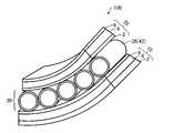
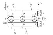
図1は、本実施形態に係るアクチュエーター100を模式的に示す斜視図である。図2は、本実施形態に係るアクチュエーター100の縦断面の模式図である。
1. 1. First Embodiment 1.1. Structure of Actuator FIG. 1 is a perspective view schematically showing anactuator 100 according to the present embodiment. FIG. 2 is a schematic view of a vertical cross section of theactuator 100 according to the present embodiment.

本実施形態のアクチュエーター100は、中間層30と、中間層30を挟んで対向して配置される第1駆動層10及び第2駆動層20と、を含む。本実施形態に係るアクチュエーター100は、図1及び図2に示すように、第1駆動層10及び第2駆動層20の2つの駆動層によって中間層30が狭持されており、第1駆動層10、中間層30及び第2駆動層20が、順に積層された構造となっている。 Theactuator 100 of the present embodiment includes anintermediate layer 30 and afirst drive layer 10 and asecond drive layer 20 arranged so as to face each other with theintermediate layer 30 interposed therebetween. As shown in FIGS. 1 and 2, in theactuator 100 according to the present embodiment, theintermediate layer 30 is sandwiched by the two drive layers of thefirst drive layer 10 and thesecond drive layer 20, and the first drive layer is sandwiched. 10. Theintermediate layer 30 and thesecond drive layer 20 are laminated in this order.

1.1.1.第1駆動層
第1駆動層10は、第1電極2、誘電エラストマー層4及び第2電極6を含む。第1電極2、誘電エラストマー層4及び第2電極6は順次積層されており、第1電極2及び第2電極6の間に誘電エラストマー層4が配置された構造となっている。
1.1.1. First Drive Layer Thefirst drive layer 10 includes afirst electrode 2, adielectric elastomer layer 4, and asecond electrode 6. Thefirst electrode 2, thedielectric elastomer layer 4 and thesecond electrode 6 are sequentially laminated, and thedielectric elastomer layer 4 is arranged between thefirst electrode 2 and thesecond electrode 6.

第1電極2は、第2電極6と対になって誘電エラストマー層4に対して電圧(電界)を印加する一方の電極である。第1電極2は、電圧を印加する機能を発揮でき、かつ誘電エラストマー層4の変形に追従できればよく、形状、材質、電気抵抗等は限定されない。第1電極2の形状としては、例えば、平板状、フィルム状、塗膜状等である。第1電極2には1つ以上の孔が開いていてもよく、例えば、平面的に見てスリット等が形成されてもよい。また、例えば、第1電極2は、平面的に見て櫛形、網目等の形状となっていてもよい。 Thefirst electrode 2 is one electrode that is paired with thesecond electrode 6 and applies a voltage (electric field) to thedielectric elastomer layer 4. Thefirst electrode 2 is not limited in shape, material, electrical resistance, etc., as long as it can exert a function of applying a voltage and can follow the deformation of thedielectric elastomer layer 4. The shape of thefirst electrode 2 is, for example, a flat plate shape, a film shape, a coating film shape, or the like. Thefirst electrode 2 may have one or more holes, and for example, a slit or the like may be formed when viewed in a plane. Further, for example, thefirst electrode 2 may have a shape such as a comb shape or a mesh when viewed in a plane.

第1電極2が第2電極6とともに狭持する誘電エラストマー層4の領域は、誘電エラストマー層4の全体であってもよいし、誘電エラストマー層4の一部であってもよい。第1電極2と誘電エラストマー層4とは、直接接していてもよいし、例えば、接着層等の他の層を介して接していてもよい。 The region of thedielectric elastomer layer 4 narrowed by thefirst electrode 2 together with thesecond electrode 6 may be the entiredielectric elastomer layer 4 or a part of thedielectric elastomer layer 4. Thefirst electrode 2 and thedielectric elastomer layer 4 may be in direct contact with each other, or may be in contact with each other via another layer such as an adhesive layer.

第1電極2の材質としては、導電性を有する材質であって、例えば、アルミニウム、銅、金等の金属、各種金属の合金、カーボン、導電性酸化物、導電性ポリマー、導電性ペースト等を例示できる。 The material of thefirst electrode 2 is a material having conductivity, for example, a metal such as aluminum, copper, or gold, an alloy of various metals, carbon, a conductive oxide, a conductive polymer, a conductive paste, or the like. It can be exemplified.

また、第1電極2は、誘電エラストマー層4の変形に対して追従できるような材質であることがより好ましい。また、第1電極2の材質として、例えば、導電性ポリマーやカーボンペースト、銀ペースト等を採用することにより、誘電エラストマー層4の変形に追従して変形し易くできる。 Further, it is more preferable that thefirst electrode 2 is made of a material that can follow the deformation of thedielectric elastomer layer 4. Further, by adopting, for example, a conductive polymer, carbon paste, silver paste, or the like as the material of thefirst electrode 2, thedielectric elastomer layer 4 can be easily deformed by following the deformation.

第1電極2の厚さは、材質に依存するが、例えば、導電性の塗膜である場合には、1μm以上500μm以下であり、好ましくは5μm以上300μm以下、より好ましくは10μm以上200μm以下である。 The thickness of thefirst electrode 2 depends on the material, but for example, in the case of a conductive coating film, it is 1 μm or more and 500 μm or less, preferably 5 μm or more and 300 μm or less, and more preferably 10 μm or more and 200 μm or less. be.

第2電極6は、第1電極2と対になって誘電エラストマー層4に対して電圧(電界)を印加する他方の電極である。第2電極6は、電圧を印加する機能を発揮でき、かつ、誘電エラストマー層4の変形に追従できればよく、形状、材質等は限定されない。第2電極6の形状は、上記の第1電極2と同様である。また、第2電極6が第1電極2とともに狭持する誘電エラストマー層4の領域、第2電極6の材質及び厚さについても上記の第1電極2と同様である。 Thesecond electrode 6 is the other electrode paired with thefirst electrode 2 to apply a voltage (electric field) to thedielectric elastomer layer 4. Thesecond electrode 6 is not limited in shape, material, etc., as long as it can exert a function of applying a voltage and can follow the deformation of thedielectric elastomer layer 4. The shape of thesecond electrode 6 is the same as that of thefirst electrode 2 described above. Further, the region of thedielectric elastomer layer 4 held by thesecond electrode 6 together with thefirst electrode 2, the material and the thickness of thesecond electrode 6 are the same as those of thefirst electrode 2.

誘電エラストマー層4は、第1電極2及び第2電極6に狭持される。誘電エラストマー層4は、第1電極2及び第2電極6に電圧が印加されたときに、第1電極2と第2電極6とがクーロン力によって引き合うことにより、厚さ方向に圧縮される。これにより、誘電エラストマー層4の厚さ方向に直交する方向に、第1駆動層10が伸びることができる。本実施形態においては、厚さ方向はz軸に沿う方向である。 Thedielectric elastomer layer 4 is sandwiched between thefirst electrode 2 and thesecond electrode 6. When a voltage is applied to thefirst electrode 2 and thesecond electrode 6, thedielectric elastomer layer 4 is compressed in the thickness direction by attracting thefirst electrode 2 and thesecond electrode 6 by Coulomb force. As a result, thefirst drive layer 10 can be extended in a direction orthogonal to the thickness direction of thedielectric elastomer layer 4. In the present embodiment, the thickness direction is the direction along the z-axis.

誘電エラストマー層4は、あらかじめ第1方向に延伸された状態で第1電極2及び第2電極6に狭持される。又は、誘電エラストマー層4は、延伸される前に第1電極2及び第2電極6と積層されて第1駆動層10となった後、第1駆動層10が第1方向に延伸されて第1電極2及び第2電極6に狭持される。これらのいずれの場合においても、アクチュエーター100が形成された時点において、誘電エラストマー層4は、あらかじめ第1方向に延伸された状態で中間層30に固定されることとなる。第1駆動層10は、誘電エラストマー層4が第1方向に延伸された状態であるので、第1方向に収縮しようとする復元力を有している。 Thedielectric elastomer layer 4 is sandwiched between thefirst electrode 2 and thesecond electrode 6 in a state of being stretched in the first direction in advance. Alternatively, thedielectric elastomer layer 4 is laminated with thefirst electrode 2 and thesecond electrode 6 to form thefirst drive layer 10 before being stretched, and then thefirst drive layer 10 is stretched in the first direction. It is narrowly held by the 1electrode 2 and the2nd electrode 6. In any of these cases, when theactuator 100 is formed, thedielectric elastomer layer 4 is fixed to theintermediate layer 30 in a state of being previously stretched in the first direction. Since thefirst drive layer 10 is in a state where thedielectric elastomer layer 4 is stretched in the first direction, it has a restoring force that tends to shrink in the first direction.

ここで「第1方向」とは、誘電エラストマー層4の厚さ方向に直交する方向である。また、第1方向は、誘電エラストマー層4の第1電極2又は第2電極6との境界面に沿う方向である。本実施形態においては、第1方向はx軸に沿った正又は負の方向である。 Here, the "first direction" is a direction orthogonal to the thickness direction of thedielectric elastomer layer 4. Further, the first direction is a direction along the boundary surface of thedielectric elastomer layer 4 with thefirst electrode 2 or thesecond electrode 6. In this embodiment, the first direction is a positive or negative direction along the x-axis.

誘電エラストマー層4は、第1方向に延伸された状態でアクチュエーター100の一部材となっているが、第1方向に交差する方向(誘電エラストマー層4の第1電極2又は第2電極6との境界面に沿う方向)に延伸された状態であってもよい。例えば、誘電エラストマー層4は、第1方向に直交する第2方向に延伸されていてもよい。 Thedielectric elastomer layer 4 is a member of theactuator 100 in a state of being stretched in the first direction, but is in a direction intersecting the first direction (with thefirst electrode 2 or thesecond electrode 6 of the dielectric elastomer layer 4). It may be in a state of being stretched in the direction along the boundary surface). For example, thedielectric elastomer layer 4 may be stretched in a second direction orthogonal to the first direction.

ここで「第2方向」とは、誘電エラストマー層4の第1電極2又は第2電極6との境界面に沿う方向であって、第1方向に直交する方向である。本実施形態においては、第2方向は、y軸に沿った正又は負の方向である。 Here, the "second direction" is a direction along the boundary surface of thedielectric elastomer layer 4 with thefirst electrode 2 or thesecond electrode 6, and is a direction orthogonal to the first direction. In this embodiment, the second direction is a positive or negative direction along the y-axis.

誘電エラストマー層4は、延伸された状態でアクチュエーター100を構成するが、当該延伸は一軸又は多軸の延伸であってよく、収縮しようとする復元力が第1方向の成分を含んでいればよい。 Thedielectric elastomer layer 4 constitutes theactuator 100 in a stretched state, but the stretching may be uniaxial or multiaxial stretching, and the restoring force to be contracted may include a component in the first direction. ..

誘電エラストマー層4が延伸された状態で第1駆動層10が中間層30に固定されることによって、誘電エラストマー層4の厚さが小さくなり、第1電極2と第2電極6とに電場を印加した際に生じるクーロン力をより大きくすることができる。そのため、延伸しない場合と比較して、第1方向の変形をより大きくすることができる。また、誘電エラストマー層4が延伸されて中間層30に固定されることによって、誘電エラストマー層4のヤング率が低く曲げやすい伸張領域での動作を利用しやすくなり、アクチュエーター100の動作における早い応答性及び小さい電力による大きな変形を得やすくなる。 By fixing thefirst drive layer 10 to theintermediate layer 30 in a state where thedielectric elastomer layer 4 is stretched, the thickness of thedielectric elastomer layer 4 is reduced, and an electric field is applied to thefirst electrode 2 and thesecond electrode 6. The Coulomb force generated when applied can be made larger. Therefore, the deformation in the first direction can be made larger than that in the case of not stretching. Further, since thedielectric elastomer layer 4 is stretched and fixed to theintermediate layer 30, it becomes easy to utilize the operation in the stretched region where the Young's modulus of thedielectric elastomer layer 4 is low and it is easy to bend, and the quick response in the operation of theactuator 100 becomes easy. And it becomes easy to obtain a large deformation due to a small power.

誘電エラストマー層4の延伸率が低すぎると、アクチュエーター100の動作時のゴム弾性による復元力が低くなることで変形量が低下し、誘電エラストマー層4の延伸率が高すぎると、アクチュエーター100の動作時に破断伸びに近い領域で動作することとなるので、動作中に破断してしまうおそれがある。そのため、採用する材料や厚さに応じて適宜の延伸率とすることが好ましい。 If the stretch ratio of thedielectric elastomer layer 4 is too low, the restoring force due to rubber elasticity during operation of theactuator 100 is low, so that the amount of deformation is reduced. If the stretch ratio of thedielectric elastomer layer 4 is too high, theactuator 100 operates. Since it sometimes operates in a region close to the breaking elongation, there is a risk of breaking during operation. Therefore, it is preferable to set an appropriate stretching ratio according to the material and thickness to be used.

誘電エラストマー層4の厚さは、10μm以上1mm以下、好ましくは10μm以上800μm以下、より好ましくは50μm以上500μm以下、さらに好ましくは100μm以上500μm以下である。誘電エラストマー層4の厚さが薄過ぎると、アクチュエーター100の組立工程において誘電エラストマー層4が破れやすくなる場合がある。また、誘電エラストマー層4の厚さが厚過ぎると、誘電エラストマー層4の弾性が大きくなり、2軸の延伸が困難となる場合がある。さらに、アクチュエーター100の動作時の電極間の距離が大きくなるため印加電圧に対する応答性が低下する傾向がある。 The thickness of thedielectric elastomer layer 4 is 10 μm or more and 1 mm or less, preferably 10 μm or more and 800 μm or less, more preferably 50 μm or more and 500 μm or less, and further preferably 100 μm or more and 500 μm or less. If the thickness of thedielectric elastomer layer 4 is too thin, thedielectric elastomer layer 4 may be easily torn in the assembly process of theactuator 100. Further, if the thickness of thedielectric elastomer layer 4 is too thick, the elasticity of thedielectric elastomer layer 4 becomes large, and biaxial stretching may be difficult. Further, since the distance between the electrodes during the operation of theactuator 100 becomes large, the responsiveness to the applied voltage tends to decrease.

誘電エラストマー層4の材質としては、絶縁性を有し、ゴム弾性を有するものであれば特に限定されず、例えば、天然ゴム、イソプレンゴム、スチレン-ブタジエンゴム(SB
R)、ニトリルゴム(NBR)、エチレン・プロピレン・ジエンゴム(EPDM)、アクリルゴム、シリコーンゴム、ウレタンゴム、アクリル系エラストマー等が挙げられる。これらの中でも、誘電エラストマー層4に用いる材料としては、シリコーンゴムやウレタンゴム、アクリル系エラストマーなどがより好適である。
The material of thedielectric elastomer layer 4 is not particularly limited as long as it has insulating properties and rubber elasticity, and is, for example, natural rubber, isoprene rubber, and styrene-butadiene rubber (SB).
R), nitrile rubber (NBR), ethylene / propylene / diene rubber (EPDM), acrylic rubber, silicone rubber, urethane rubber, acrylic elastomer and the like can be mentioned. Among these, as the material used for thedielectric elastomer layer 4, silicone rubber, urethane rubber, acrylic elastomer and the like are more suitable.

また、誘電エラストマー層4に用いる材料は、剛性が低くかつ高伸びを有した材料が好適である。具体的には、誘電エラストマー層4に用いる材料の機械的物性としては、JIS K6251に基づく引っ張り試験における600%伸張時のモジュラスが0.03MPa以上1.0MPa以下、好ましくは0.03MPa以上0.5MPa以下、より好ましくは0.05MPa以上0.3MPa以下の範囲、かつ、破断伸びが800%以上、好ましくは1000%以上である材料がさらに適している。 Further, as the material used for thedielectric elastomer layer 4, a material having low rigidity and high elongation is preferable. Specifically, as the mechanical properties of the material used for thedielectric elastomer layer 4, the modulus at 600% elongation in the tensile test based on JIS K6251 is 0.03 MPa or more and 1.0 MPa or less, preferably 0.03 MPa or more and 0. Further suitable materials are 5 MPa or less, more preferably 0.05 MPa or more and 0.3 MPa or less, and a breaking elongation of 800% or more, preferably 1000% or more.

第1駆動層10は、誘電エラストマー層4が第1方向に延伸された状態となっているので、第1方向に収縮しようとする復元力を有している。すなわち、アクチュエーター100が形成されたとき、第1駆動層10は、常にゴム弾性によって元の形状に戻ろうとしている状態となる。本実施形態のアクチュエーター100では、第1方向に収縮しようとする復元力を有する第1駆動層10を中間層30に固定化し、後述の第2駆動層20とともに中間層30を挟んで両側で復元力が釣り合った状態で延伸状態が維持されるように固定される。 Since thedielectric elastomer layer 4 is in a state of being stretched in the first direction, thefirst driving layer 10 has a restoring force that tends to shrink in the first direction. That is, when theactuator 100 is formed, thefirst drive layer 10 is always in a state of returning to its original shape due to rubber elasticity. In theactuator 100 of the present embodiment, thefirst drive layer 10 having a restoring force that tends to contract in the first direction is fixed to theintermediate layer 30, and is restored on both sides of theintermediate layer 30 together with thesecond drive layer 20 described later. It is fixed so that the stretched state is maintained in a state where the forces are balanced.

1.1.2.第2駆動層
第2駆動層20は、中間層30を挟んで第1駆動層10と対向して配置されている。第2駆動層20は、本実施形態では第1駆動層10と同様に第1電極2、誘電エラストマー層4及び第2電極6を含む。第1電極2、誘電エラストマー層4及び第2電極6の形状、機能、材質、物性等は、上述した第1駆動層10と同様である。
11.2. Second Drive Layer Thesecond drive layer 20 is arranged so as to face thefirst drive layer 10 with theintermediate layer 30 interposed therebetween. In the present embodiment, thesecond drive layer 20 includes thefirst electrode 2, thedielectric elastomer layer 4, and thesecond electrode 6 as in thefirst drive layer 10. The shapes, functions, materials, physical properties, etc. of thefirst electrode 2, thedielectric elastomer layer 4, and thesecond electrode 6 are the same as those of thefirst drive layer 10 described above.

第2駆動層20においても、誘電エラストマー層4が、延伸されることによって、誘電エラストマー層4の厚さが小さくなり、第1電極2と第2電極6とに電場を印加した際に生じるクーロン力をより大きくすることができる。そのため、延伸しない場合と比較して、より大きく第1方向に第2駆動層20を変形させることができる。また、誘電エラストマー層4が、延伸されることによって、誘電エラストマー層4のヤング率が低く曲げやすい伸張領域での動作を利用しやすくなり、早い応答性及び小さい電力による大きな変形を得やすくなる。 Also in thesecond drive layer 20, the thickness of thedielectric elastomer layer 4 is reduced by stretching thedielectric elastomer layer 4, and Coulomb generated when an electric field is applied to thefirst electrode 2 and thesecond electrode 6. The force can be increased. Therefore, thesecond drive layer 20 can be deformed more in the first direction as compared with the case where it is not stretched. Further, by stretching thedielectric elastomer layer 4, it becomes easy to utilize the operation in the stretched region where the Young's modulus of thedielectric elastomer layer 4 is low and it is easy to bend, and it becomes easy to obtain a quick response and a large deformation due to a small electric power.

第2駆動層20は、アクチュエーター100を構成した場合には、上述の第1駆動層10と同様に、第1方向に延伸された状態であるので、第1方向に収縮しようとする復元力を有している。すなわち、アクチュエーター100を構成した場合、第2駆動層20も、常にゴム弾性によって元の形状に戻ろうとしている状態となっている。この第1方向に収縮しようとする復元力を有する第2駆動層20を中間層30に固定化し、上述の第1駆動層10とともに中間層30を挟んで両側で、第1駆動層10の復元力と第2駆動層20の復元力が、釣り合った状態で延伸状態が維持されるように固定される。 When theactuator 100 is configured, thesecond drive layer 20 is in a state of being stretched in the first direction as in the case of thefirst drive layer 10 described above, so that the restoring force that tends to contract in the first direction is exerted. Have. That is, when theactuator 100 is configured, thesecond drive layer 20 is also in a state of always trying to return to its original shape due to rubber elasticity. Thesecond drive layer 20 having a restoring force that tends to contract in the first direction is fixed to theintermediate layer 30, and thefirst drive layer 10 is restored on both sides of theintermediate layer 30 together with the above-mentionedfirst drive layer 10. The force and the restoring force of thesecond drive layer 20 are fixed so as to be maintained in a stretched state in a balanced state.

なお、アクチュエーター100では、図1に示すように、第1駆動層10の第2電極6が中間層30側に配置されており、第2駆動層20の第1電極2が中間層30側に配置されている。しかし第1駆動層10及び第2駆動層20の第1電極2及び第2電極6は、いずれが中間層30側に配置されてもよい。 In theactuator 100, as shown in FIG. 1, thesecond electrode 6 of thefirst drive layer 10 is arranged on theintermediate layer 30 side, and thefirst electrode 2 of thesecond drive layer 20 is on theintermediate layer 30 side. Have been placed. However, any of thefirst electrode 2 and thesecond electrode 6 of thefirst drive layer 10 and thesecond drive layer 20 may be arranged on theintermediate layer 30 side.

1.1.3.中間層
中間層30は、抑制部材36を含む。抑制部材36は、第1駆動層10に接着する第1接着部32と、第2駆動層20に接着する第2接着部34とを有する。
11.3. Intermediate layer Theintermediate layer 30 includes a restrainingmember 36. The restrainingmember 36 has a firstadhesive portion 32 that adheres to thefirst drive layer 10 and a secondadhesive portion 34 that adheres to thesecond drive layer 20.

第1接着部32は、抑制部材36の第1駆動層10に接着する部分である。第1接着部32は複数設けられる。また第1接着部32は、第1駆動層10の第2電極6に接着していてもよいし、例えば、第2電極6に孔が存在する場合には、当該孔の内側で誘電エラストマー層4に接着していてもよい。 The firstadhesive portion 32 is a portion that adheres to thefirst drive layer 10 of the restrainingmember 36. A plurality of firstadhesive portions 32 are provided. Further, the firstadhesive portion 32 may be adhered to thesecond electrode 6 of thefirst drive layer 10. For example, when a hole is present in thesecond electrode 6, the dielectric elastomer layer is formed inside the hole. It may be adhered to 4.

第1接着部32は、第1方向において隣り合う第1接着部32が互いに第1間隔P1を隔てて配置される。図示の例では複数存在する第1間隔P1は、互いに等しい間隔であるが、抑制部材36の形状によっては、複数の第1間隔P1の全てが互いに同じでも異なってもよい。 In the firstadhesive portion 32, the firstadhesive portions 32 adjacent to each other in the first direction are arranged so as to be separated from each other by the first interval P1. In the illustrated example, the plurality of first spacing P1s are equal to each other, but depending on the shape of the restrainingmember 36, all of the plurality of first spacings P1 may be the same or different from each other.

第1接着部32は、中間層30が展開する面における第1方向に交差する第2方向に沿う直線上にあるように配置されている。各駆動層と抑制部材36とは、第2方向に沿って連続的に接着されてもよいし、不連続に接着されてもよい。図1及び図2の例では、第1接着部32は、第1方向(x)に直交する第2方向(y)に沿って、直線状に形成されている。 The firstadhesive portion 32 is arranged so as to be on a straight line along a second direction intersecting the first direction on the surface on which theintermediate layer 30 develops. Each drive layer and the restrainingmember 36 may be continuously bonded or discontinuously bonded along the second direction. In the examples of FIGS. 1 and 2, the firstadhesive portion 32 is formed linearly along the second direction (y) orthogonal to the first direction (x).

第2接着部34は、抑制部材36の第2駆動層20に接着する部分である。第2接着部34の数、第2駆動層20との接着の態様については第1接着部32と同様である。第2接着部34は、第1接着部32と同様に第1方向(x)に直交する第2方向(y)に沿って、直線上に形成されている。 The secondadhesive portion 34 is a portion that adheres to thesecond drive layer 20 of the restrainingmember 36. The number of the secondadhesive portions 34 and the mode of adhesion with thesecond drive layer 20 are the same as those of the firstadhesive portions 32. The secondadhesive portion 34 is formed on a straight line along the second direction (y) orthogonal to the first direction (x) like the firstadhesive portion 32.

第2接着部34は、第1方向において隣り合う第2接着部34が互いに第2間隔P2を隔てて配置される。図示の例では、第1間隔P1及び第2間隔P2は、等しくなっている。また図示において複数存在する第2間隔P2は、互いに等しい間隔であるが、複数の第2間隔P2は互いに同じでも異なってもよい。 In the secondadhesive portion 34, the secondadhesive portions 34 adjacent to each other in the first direction are arranged so as to be separated from each other by the second interval P2. In the illustrated example, the first interval P1 and the second interval P2 are equal. Further, although the plurality of second intervals P2 existing in the drawing are equal to each other, the plurality of second intervals P2 may be the same or different from each other.

第1接着部32及び第2接着部34には、接着剤を用いることができる。接着剤は、電極層や誘電エラストマー層4の材質に合わせて相溶性の高い材質のものを選ぶことが好ましい。例えば、抑制部材36が誘電エラストマー層4と接着される場合であって誘電エラストマー層4がシリコーンゴムである場合、シリコーン系の接着剤を用いることが好ましい。また電極層が導電性ペーストに接着剤成分が含まれている場合などには、接着剤を用いることなく抑制部材36を電極層と該導電性ペーストによって接着することも可能である。 An adhesive can be used for the firstadhesive portion 32 and the secondadhesive portion 34. It is preferable to select an adhesive having a high compatibility with the material of the electrode layer and thedielectric elastomer layer 4. For example, when the restrainingmember 36 is adhered to thedielectric elastomer layer 4, and thedielectric elastomer layer 4 is made of silicone rubber, it is preferable to use a silicone-based adhesive. Further, when the electrode layer contains an adhesive component in the conductive paste, the suppressingmember 36 can be adhered to the electrode layer by the conductive paste without using an adhesive.

抑制部材36は、第1間隔P1及び第2間隔P2が、誘電エラストマー層4(第1駆動層10及び第2駆動層20)の復元力によって第1方向に狭まることを制限する。なお、第1電極2及び第2電極6に電圧が印加されて、第1駆動層10及び第2駆動層20のいずれかが動作した場合には、第1間隔P1又は第2間隔P2の間隔が狭まることが許容される。 The restrainingmember 36 limits the first spacing P1 and the second spacing P2 from being narrowed in the first direction by the restoring force of the dielectric elastomer layer 4 (first driving layer 10 and second driving layer 20). When a voltage is applied to thefirst electrode 2 and thesecond electrode 6 and either thefirst drive layer 10 or thesecond drive layer 20 operates, the interval between the first interval P1 and the second interval P2 Is allowed to narrow.

抑制部材36は、図1及び図2の例では、第1方向に直交する第2方向に延びる棒部材42を複数含み、棒部材42の第2方向に垂直な断面の外形が円形であり、隣り合う前記棒部材42が、互いに接触する状態で第1方向に配置され、第1接着部32及び第2接着部34が、それぞれ棒部材42の外周面の一部となっている。また図示の例では第1接着部32及び第2接着部34は、棒部材42の中心軸を挟んで対向した位置にある。 In the examples of FIGS. 1 and 2, the restrainingmember 36 includes a plurality ofrod members 42 extending in a second direction orthogonal to the first direction, and the outer shape of the cross section of therod member 42 perpendicular to the second direction is circular. Theadjacent rod members 42 are arranged in the first direction in a state of being in contact with each other, and the firstadhesive portion 32 and the secondadhesive portion 34 are each a part of the outer peripheral surface of therod member 42. Further, in the illustrated example, the firstadhesive portion 32 and the secondadhesive portion 34 are located at positions facing each other with the central axis of therod member 42 interposed therebetween.

抑制部材36と電極層及び/又は誘電エラストマー層4との接着面積(各接着部の面積)はより小さい方が好ましい。接着部の面積が大きくなるにつれ、誘電エラストマー層4の第1方向への伸長変形を拘束しやすくなり、アクチュエーターの変位量が低下する傾向
がある。
It is preferable that the bonding area (area of each bonded portion) between the suppressingmember 36 and the electrode layer and / or thedielectric elastomer layer 4 is smaller. As the area of the bonded portion increases, it becomes easier to restrain the elongation deformation of thedielectric elastomer layer 4 in the first direction, and the displacement amount of the actuator tends to decrease.

また、図示の例では、棒部材42は、中空の円筒状であるが、中実の円柱状であってもよい。また、隣り合う棒部材42の間は、接着されずに接触している。隣り合う棒部材42の間が接触していれば、第1間隔P1及び第2間隔P2が、第1駆動層10及び第2駆動層20の復元力によって第1方向に狭まることを制限できる。また、隣り合う棒部材42の間が接着されていないことにより、アクチュエーター100をより変形しやすくできる。すなわち隣り合う棒部材42の間が接着されていないので、隣り合う棒部材42が回転しながら相対的な位置の変化を容易に行うことができる構造となる。 Further, in the illustrated example, therod member 42 has a hollow cylindrical shape, but may be a solid cylindrical shape. Further, theadjacent rod members 42 are in contact with each other without being adhered to each other. If theadjacent rod members 42 are in contact with each other, it is possible to limit the first interval P1 and the second interval P2 from being narrowed in the first direction by the restoring force of thefirst drive layer 10 and thesecond drive layer 20. Further, since theadjacent rod members 42 are not adhered to each other, theactuator 100 can be more easily deformed. That is, since theadjacent rod members 42 are not adhered to each other, the structure is such that theadjacent rod members 42 can easily change their relative positions while rotating.

棒部材42の材質としては、金属、セラミックス、樹脂材料などが適用できる。特に、隣り合う棒部材42の間が接着されず接触しているので、結晶性が高く低摩擦係数かつ高ヤング率、を示す材質が好ましい。そのような材質としては、ポリエーテルエーテルケトン、ポリイミドなどのエンジニアリングプラスチック材料が挙げられる。また、棒部材42と第1駆動層10及び第2駆動層20との間(中間層30の抑制部材36以外の部分)には、厚さ方向への中間層30の変形を抑制しない弾性体を満たしてもよい。弾性体としては、天然ゴム、イソプレンゴム、スチレン-ブタジエンゴム(SBR)、ニトリルゴム(NBR)、エチレン・プロピレン・ジエンゴム(EPDM)、アクリルゴム、シリコーンゴム、ウレタンゴム等のゴム、スチレン系、オレフィン/アルケン系、塩化ビニル系、ウレタン系、アミド系の熱可塑性樹脂、及びその発泡体などの柔軟な材料を用いることができる。 As the material of therod member 42, a metal, ceramics, a resin material, or the like can be applied. In particular, since theadjacent rod members 42 are not adhered to each other and are in contact with each other, a material having high crystallinity, a low coefficient of friction and a high Young's modulus is preferable. Examples of such materials include engineering plastic materials such as polyetheretherketone and polyimide. Further, between therod member 42 and thefirst drive layer 10 and the second drive layer 20 (a portion of theintermediate layer 30 other than the restraining member 36), an elastic body that does not suppress the deformation of theintermediate layer 30 in the thickness direction. May be satisfied. As the elastic body, natural rubber, isoprene rubber, styrene-butadiene rubber (SBR), nitrile rubber (NBR), ethylene / propylene / diene rubber (EPDM), acrylic rubber, silicone rubber, urethane rubber and other rubbers, styrene-based, olefins. / Flexible materials such as alkene-based, vinyl chloride-based, urethane-based, amide-based thermoplastic resins, and foams thereof can be used.

なお本実施形態では、第1駆動層10及び第2駆動層20の2つの駆動層によって中間層30が狭持されている例を説明したが、これに限らず、駆動層と中間層30の間に他の層を有してもよいし、駆動層の中まで中間層30の一部が入り込んでもよい。 In the present embodiment, an example in which theintermediate layer 30 is sandwiched by the two drive layers of thefirst drive layer 10 and thesecond drive layer 20 has been described, but the present invention is not limited to this, and the drive layer and theintermediate layer 30 are not limited to this. Another layer may be provided between the layers, or a part of theintermediate layer 30 may enter into the driving layer.

1.2.アクチュエーターの動作
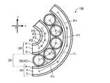
図3は、本実施形態のアクチュエーター100の動作を模式的に示す斜視図である。図4は、本実施形態に係るアクチュエーター100が動作した場合の縦断面の模式図である。
1.2. Actuator Operation FIG. 3 is a perspective view schematically showing the operation of theactuator 100 of the present embodiment. FIG. 4 is a schematic view of a vertical cross section when theactuator 100 according to the present embodiment operates.

図3及び図4の例は、本実施形態のアクチュエーター100の第1駆動層10の第1電極2と第2電極6との間に電圧が印加され、両電極間にクーロン力が生じた場合を示している。第1駆動層10の第1電極2と第2電極6との間に電圧が印加された場合、第1駆動層10の第1方向への伸びが発生する。 In the examples of FIGS. 3 and 4, a voltage is applied between thefirst electrode 2 and thesecond electrode 6 of thefirst drive layer 10 of theactuator 100 of the present embodiment, and a Coulomb force is generated between the two electrodes. Is shown. When a voltage is applied between thefirst electrode 2 and thesecond electrode 6 of thefirst drive layer 10, thefirst drive layer 10 is stretched in the first direction.

第1駆動層10が第1方向に伸びると、アクチュエーター100は、第1駆動層10の伸びに基づく屈曲変形と、第2駆動層20の復元力による屈曲変形とが生じる。すなわち、本実施形態のアクチュエーター100では、第1駆動層10の伸びによって第1駆動層10の復元力と第2駆動層20の復元力の釣り合いが崩れ、伸びに基づく屈曲変形及び復元力に基づく屈曲変形の2つの機構によって屈曲変形を起こす。このように誘電エラストマー層4を第1方向に延伸して用いることにより、アクチュエーター100の変位量を非常に大きくできる。 When thefirst drive layer 10 extends in the first direction, theactuator 100 undergoes bending deformation due to the elongation of thefirst drive layer 10 and bending deformation due to the restoring force of thesecond drive layer 20. That is, in theactuator 100 of the present embodiment, the balance between the restoring force of thefirst drive layer 10 and the restoring force of thesecond drive layer 20 is lost due to the elongation of thefirst drive layer 10, and it is based on the bending deformation and the restoring force based on the elongation. Bending deformation is caused by two mechanisms of bending deformation. By stretching thedielectric elastomer layer 4 in the first direction in this way and using it, the displacement amount of theactuator 100 can be made very large.

アクチュエーター100の第1駆動層10が第1方向に伸びる場合の屈曲変形は、x軸のプラス側に向かう方向がz軸のプラス側向かう方向に屈曲するような変形である。図示の例では、z軸のマイナス側に第1駆動層10が存在しており、第1駆動層10の伸長により、第2駆動層20が内側となるように湾曲する。すなわち、x-y平面に展開するアクチュエーター100が、z軸に沿った方向(厚さ方向)に屈曲する。このとき棒部材42は、隣り合う棒部材42の外周に沿って移動する。なお、本実施形態において、誘電エ
ラストマー層4の厚さ方向を第3方向ということがあり、第3方向は、x軸及びy軸に直交するz軸に沿った正又は負の方向である。
The bending deformation when thefirst drive layer 10 of theactuator 100 extends in the first direction is such that the direction toward the plus side of the x-axis bends toward the plus side of the z-axis. In the illustrated example, thefirst drive layer 10 exists on the minus side of the z-axis, and the extension of thefirst drive layer 10 causes thesecond drive layer 20 to bend inward. That is, theactuator 100 deployed in the xy plane bends in the direction (thickness direction) along the z-axis. At this time, therod member 42 moves along the outer circumference of theadjacent rod member 42. In the present embodiment, the thickness direction of thedielectric elastomer layer 4 may be referred to as a third direction, and the third direction is a positive or negative direction along the z-axis orthogonal to the x-axis and the y-axis.

また、アクチュエーター100は、y軸のプラス側に向かう方向がz軸のプラス側向かう方向となるような屈曲は、ほとんど又は全く生じない。これは棒部材42が第2方向に延在し、第1駆動層10及び第2駆動層20の第2方向への変形を拘束していることによる。 Further, theactuator 100 hardly or at all bends so that the direction toward the plus side of the y-axis is the direction toward the plus side of the z-axis. This is because therod member 42 extends in the second direction and restrains the deformation of thefirst drive layer 10 and thesecond drive layer 20 in the second direction.

第1駆動層10の第1電極2と第2電極6とに、互いに異なる極性の電位を印加すれば、第1駆動層10を第1方向に伸ばすことができる。また、第1電極2及び第2電極6のいずれかを接地電位としてもよい。このような電位は、例えば、公知の電圧発生装置(電池、電圧印加回路等)により印加することができる。 If potentials having different polarities are applied to thefirst electrode 2 and thesecond electrode 6 of thefirst drive layer 10, thefirst drive layer 10 can be extended in the first direction. Further, either thefirst electrode 2 or thesecond electrode 6 may be used as the ground potential. Such a potential can be applied, for example, by a known voltage generator (battery, voltage application circuit, etc.).

図2及び図4を用いて、本実施形態のアクチュエーター100の屈曲構造における棒部材42の力学的モデルを説明する。図2の状態では、第1駆動層10及び第2駆動層20が駆動しておらず、棒部材42は、隣接する棒部材42と接触している。これにより第1間隔P1及び第2間隔P2が、棒部材42によって一定に維持されている。また図2の状態では、第1駆動層10及び第2駆動層20における誘電エラストマー層4の復元力は、第1方向において釣り合っており、アクチュエーター100が屈曲せず平面的な形状となっている。 A mechanical model of therod member 42 in the bending structure of theactuator 100 of the present embodiment will be described with reference to FIGS. 2 and 4. In the state of FIG. 2, thefirst drive layer 10 and thesecond drive layer 20 are not driven, and therod member 42 is in contact with theadjacent rod member 42. As a result, the first interval P1 and the second interval P2 are kept constant by therod member 42. Further, in the state of FIG. 2, the restoring forces of thedielectric elastomer layers 4 in thefirst drive layer 10 and thesecond drive layer 20 are balanced in the first direction, and theactuator 100 does not bend and has a flat shape. ..

ここで第1駆動層10の第1電極2及び第2電極6に電圧が印加されると、図4に示す状態となる。図4の状態では、第1駆動層10が第1方向に伸びて第1間隔P1のそれぞれが拡がる。また図2の状態で第1方向において第1駆動層10の復元力と釣り合っていた第2駆動層20が、自身の復元力により収縮することにより、第2間隔P2のそれぞれが狭まる。またこのとき隣り合う棒部材42同士が接触しながら移動することで、図示のように、第2駆動層20を内側とした屈曲変形が生じる。 Here, when a voltage is applied to thefirst electrode 2 and thesecond electrode 6 of thefirst drive layer 10, the state shown in FIG. 4 is obtained. In the state of FIG. 4, thefirst drive layer 10 extends in the first direction, and each of the first intervals P1 expands. Further, in the state of FIG. 2, thesecond drive layer 20, which is balanced with the restoring force of thefirst drive layer 10 in the first direction, contracts due to its own restoring force, so that each of the second intervals P2 is narrowed. Further, at this time, theadjacent rod members 42 move while being in contact with each other, so that bending deformation occurs with thesecond drive layer 20 inside as shown in the figure.

また、図4に示すように、棒部材42は円筒状であるので、隣り合う棒部材42の中心軸間の距離Gは、屈曲した状態でも常に一定となる。このとき第1駆動層10の第2方向の変形は、第1接着部32を介して接着された棒部材42によって拘束される。 Further, as shown in FIG. 4, since therod member 42 has a cylindrical shape, the distance G between the central axes of theadjacent rod members 42 is always constant even in a bent state. At this time, the deformation of thefirst drive layer 10 in the second direction is constrained by therod member 42 bonded via thefirst bonding portion 32.

また、図示しないが、アクチュエーター100の第2駆動層20の第1電極2と第2電極6との間に電圧が印加され、両電極間にクーロン力が生じた場合では、屈曲が反対となるように動作する。 Further, although not shown, when a voltage is applied between thefirst electrode 2 and thesecond electrode 6 of thesecond drive layer 20 of theactuator 100 and a Coulomb force is generated between the two electrodes, the bending is opposite. Works like this.

1.3.駆動層のバリエーション
本実施形態のアクチュエーター100では、第1駆動層10及び第2駆動層20は、それぞれ第1電極2、誘電エラストマー層4及び第2電極6の3層の組となっており、その組が単層で構成され、誘電エラストマー層4は1層ずつ配置されている。しかし、第1駆動層10及び第2駆動層20は、いずれも誘電エラストマー層4を2層以上有してもよい。
1.3. Variation of Drive Layer In theactuator 100 of the present embodiment, thefirst drive layer 10 and thesecond drive layer 20 are a set of three layers, that is, thefirst electrode 2, thedielectric elastomer layer 4, and thesecond electrode 6, respectively. The set is composed of a single layer, and thedielectric elastomer layers 4 are arranged one by one. However, thefirst drive layer 10 and thesecond drive layer 20 may both have two or more dielectric elastomer layers 4.

例えば、第1駆動層10が誘電エラストマー層4を2層有する態様としては、第1電極2、誘電エラストマー層4、第2電極6、誘電エラストマー層4及び第1電極2の順で積層された構造としてもよい。また例えば、第1駆動層10が誘電エラストマー層4を2層有する態様としては、第1電極2、誘電エラストマー層4、第2電極6、絶縁層、第1電極2、誘電エラストマー層4及び第1電極2の順で積層された構造としてもよい。このようにすることにより、第1駆動層10の変形する力を強めることができる場合がある。第2駆動層20についても同様の構成とすることができる。なお、このような場合には、誘
電エラストマー層4の両側に電極層が存在するように構成され、1つの誘電エラストマー層4の両側の電極層には互いに極性の異なる電圧が互い違いに印加されることにより駆動する。
For example, in the embodiment in which thefirst driving layer 10 has twodielectric elastomer layers 4, thefirst electrode 2, thedielectric elastomer layer 4, thesecond electrode 6, thedielectric elastomer layer 4 and thefirst electrode 2 are laminated in this order. It may be a structure. Further, for example, as an embodiment in which thefirst driving layer 10 has twodielectric elastomer layers 4, thefirst electrode 2, thedielectric elastomer layer 4, thesecond electrode 6, the insulating layer, thefirst electrode 2, thedielectric elastomer layer 4 and thefirst electrode 2 are used. The structure may be one in which oneelectrode 2 is laminated in this order. By doing so, it may be possible to increase the deforming force of thefirst drive layer 10. Thesecond drive layer 20 can have the same configuration. In such a case, the electrode layers are configured to exist on both sides of thedielectric elastomer layer 4, and voltages having different polarities are alternately applied to the electrode layers on both sides of onedielectric elastomer layer 4. Driven by.

また、第1駆動層10及び第2駆動層20は、各層の厚さや積層数等において、同じである必要はない。例えば、中間層30の両側で第1駆動層10及び第2駆動層20のゴム弾性による復元力が釣り合っていれば、両側で誘電エラストマー層4の枚数が異なっていてもよい。 Further, thefirst drive layer 10 and thesecond drive layer 20 do not have to be the same in terms of the thickness of each layer, the number of layers, and the like. For example, the number ofdielectric elastomer layers 4 may be different on both sides as long as the restoring forces due to the rubber elasticity of thefirst drive layer 10 and thesecond drive layer 20 are balanced on both sides of theintermediate layer 30.

1.4.抑制部材のバリエーション
抑制部材36は、第1接着部32と第2接着部34とを有し、第1間隔P1及び第2間隔P2が、誘電エラストマー層4の復元力によって第1方向に狭まることを制限することができ、かつ、厚さ方向の屈曲を許容できれば、任意の形態とすることができる。
1.4. Variation of restraining member The restrainingmember 36 has a firstadhesive portion 32 and a secondadhesive portion 34, and the first interval P1 and the second interval P2 are narrowed in the first direction by the restoring force of thedielectric elastomer layer 4. Any form can be used as long as it can be restricted and bending in the thickness direction can be tolerated.

図5、図6及び図7は、変形例の抑制部材36を有するアクチュエーターの縦断面の模式図である。図5に示すアクチュエーター101では、抑制部材36は、第1方向に延びる連結部43と、連結部43から、第1方向と第1方向に直交する第2方向とに直交する第3方向に延びて第1接着部32を形成する複数の第1支持部44と、連結部43から、第3方向に延びて第2接着部34を形成する複数の第2支持部45と、から構成されている。また、連結部43、第1支持部44及び第2支持部45は、一体的に形成されている。 5, 6 and 7 are schematic cross-sectional views of a vertical cross section of an actuator having a modifiedexample suppressing member 36. In theactuator 101 shown in FIG. 5, the restrainingmember 36 extends from the connectingportion 43 extending in the first direction and the connectingportion 43 in a third direction orthogonal to the first direction and the second direction orthogonal to the first direction. It is composed of a plurality offirst support portions 44 forming the firstadhesive portion 32, and a plurality ofsecond support portions 45 extending from the connectingportion 43 in the third direction to form the secondadhesive portion 34. There is. Further, the connectingportion 43, thefirst support portion 44 and thesecond support portion 45 are integrally formed.

アクチュエーター101では、アクチュエーター101の動作を阻害しないようにするため、第1方向に並ぶ複数の第1支持部44の間の間隔(第1間隔P1)は、第1支持部44の第1方向の幅よりも広い間隔で配置することがより好ましい。第2支持部45においても、第1方向に並ぶ複数の第2支持部45の間の間隔(第2間隔P2)は、第2支持部45の第1方向の幅よりも広い間隔で配置することがより好ましい。 In theactuator 101, in order not to interfere with the operation of theactuator 101, the distance between the plurality offirst support portions 44 arranged in the first direction (first interval P1) is set to the first direction of thefirst support portion 44. It is more preferable to arrange them at intervals wider than the width. Also in thesecond support portion 45, the spacing between the plurality ofsecond support portions 45 arranged in the first direction (second spacing P2) is arranged at a wider spacing than the width of thesecond support portion 45 in the first direction. Is more preferable.

また、アクチュエーター101では、第1支持部44及び第2支持部45は、第1駆動層10及び第2駆動層20の第2方向への収縮を抑制している。また、第1駆動層10及び第2駆動層20が駆動していない状態で、連結部43が第1間隔P1及び第2間隔P2が狭まらないようにする機能を担っている。 Further, in theactuator 101, thefirst support portion 44 and thesecond support portion 45 suppress the contraction of thefirst drive layer 10 and thesecond drive layer 20 in the second direction. Further, the connectingportion 43 has a function of preventing the first interval P1 and the second interval P2 from being narrowed when thefirst drive layer 10 and thesecond drive layer 20 are not driven.

アクチュエーター101の抑制部材36の構造の利点の一つとしては、中間層30と各駆動層との接着部である第1接着部32及び第2接着部34が点接触ではなく面接触となるため、接着面積を確保しやすく、かつ第1支持部44及び第2支持部45の寸法や間隔を調節しやすいことが挙げられる。これにより第1駆動層10及び第2駆動層20の変形の形態を調整しやすくなる。 One of the advantages of the structure of the restrainingmember 36 of theactuator 101 is that the firstadhesive portion 32 and the secondadhesive portion 34, which are the adhesive portions between theintermediate layer 30 and each drive layer, are in surface contact rather than point contact. It is easy to secure an adhesive area, and it is easy to adjust the dimensions and spacing of thefirst support portion 44 and thesecond support portion 45. This makes it easy to adjust the deformation form of thefirst drive layer 10 and thesecond drive layer 20.

また、連結部43の機能としては、第1間隔P1及び第2間隔P2が狭まらないようにすることが挙げられるが、アクチュエーター101が屈曲する動作を妨げない程度のz軸方向(第1方向及び第2方向に直交する方向)の柔軟さを有することが好ましい。すなわち、連結部43の材質は、誘電エラストマー層4よりもヤング率(曲げ剛性)が低い材料が適している。 Further, the function of the connectingportion 43 is to prevent the first interval P1 and the second interval P2 from being narrowed, but the z-axis direction (first) to the extent that theactuator 101 does not interfere with the bending operation. It is preferable to have flexibility in the direction (direction orthogonal to the direction and the second direction). That is, as the material of the connectingportion 43, a material having a Young's modulus (flexural rigidity) lower than that of thedielectric elastomer layer 4 is suitable.

連結部43、第1支持部44及び第2支持部45の材質としては、ポリエチレン、ポリプロピレン、ポリ塩化ビニル、ポリ(メタ)アクリル酸などの汎用プラスチック、ポリカーボネート、ポリエーテルエーテルケトン、ポリイミドなどのエンジニアリングプラスチックなどを例示することができる。 Materials for the connectingportion 43, thefirst support portion 44, and thesecond support portion 45 include general-purpose plastics such as polyethylene, polypropylene, polyvinyl chloride, and poly (meth) acrylic acid, and engineering such as polycarbonate, polyether ether ketone, and polyimide. Examples include plastic.

なお、アクチュエーター101の例では、第1支持部44及び第2支持部45が連結部43に対して対称に配置されているが、これに限定されず、第1支持部44及び第2支持部45が断面視において連結部43を挟んでずれて(例えば千鳥状に)配置されてもよい。 In the example of theactuator 101, thefirst support portion 44 and thesecond support portion 45 are arranged symmetrically with respect to the connectingportion 43, but the present invention is not limited to this, and thefirst support portion 44 and the second support portion are not limited to this. 45 may be arranged so as to be offset (for example, in a staggered pattern) across the connectingportion 43 in a cross-sectional view.

図6に示す変形例の抑制部材36を有するアクチュエーター102において、抑制部材36は、第1方向に延びる連結部43と、連結部43から、第3方向に延びて第1接着部32を形成する複数の第1蛇腹部材46と、連結部43から、第3方向に延びて第2接着部34を形成する複数の第2蛇腹部材47と、から構成されている。また、連結部43、第1蛇腹部材46及び第2蛇腹部材47は、一体的に形成されている。 In theactuator 102 having the restrainingmember 36 of the modified example shown in FIG. 6, the restrainingmember 36 forms a connectingportion 43 extending in the first direction and a firstadhesive portion 32 extending in the third direction from the connectingportion 43. It is composed of a plurality offirst bellows members 46 and a plurality of second bellows members 47 extending from the connectingportion 43 in a third direction to form a secondadhesive portion 34. Further, the connectingportion 43, thefirst bellows member 46 and the second bellows member 47 are integrally formed.

アクチュエーター102では、第1蛇腹部材46及び第2蛇腹部材47が、第1駆動層10及び第2駆動層20の第2方向への収縮を抑制している。また、第1駆動層10及び第2駆動層20が駆動していない状態で、連結部43が第1間隔P1及び第2間隔P2が狭まらないようにする機能を担っている。 In theactuator 102, thefirst bellows member 46 and the second bellows member 47 suppress the contraction of thefirst drive layer 10 and thesecond drive layer 20 in the second direction. Further, the connectingportion 43 has a function of preventing the first interval P1 and the second interval P2 from being narrowed when thefirst drive layer 10 and thesecond drive layer 20 are not driven.

また、アクチュエーター102では、第1駆動層10及び第2駆動層20は、第1蛇腹部材46及び第2蛇腹部材47の頂点部分と接着され、第1接着部32及び第2接着部34を形成しているが、第1蛇腹部材46及び第2蛇腹部材47の頂点を滑らかあるいは平坦にして、当該接着面積を増大させてもよい。連結部43と、第1蛇腹部材46及び第2蛇腹部材47との接着部分についても同様である。 Further, in theactuator 102, thefirst drive layer 10 and thesecond drive layer 20 are adhered to the apex portions of thefirst bellows member 46 and the second bellows member 47 to form the firstadhesive portion 32 and the secondadhesive portion 34. However, the apex of thefirst bellows member 46 and the second bellows member 47 may be smoothed or flattened to increase the bonding area. The same applies to the bonded portion between the connectingportion 43 and thefirst bellows member 46 and the second bellows member 47.

アクチュエーター102の抑制部材36の構造の利点の一つとしては、アクチュエーター101の抑制部材36の構造における応力集中箇所となり得る連結部43と第1支持部44及び第2支持部45の接着端部を、第1蛇腹部材46及び第2蛇腹部材47によって解消した構造になっている点が挙げられる。 One of the advantages of the structure of the restrainingmember 36 of theactuator 102 is that the connectingportion 43, which can be a stress concentration point in the structure of the restrainingmember 36 of theactuator 101, and the adhesive end portion of thefirst support portion 44 and thesecond support portion 45 are provided. , The structure is solved by thefirst bellows member 46 and the second bellows member 47.

第1蛇腹部材46及び第2蛇腹部材47の材質としては、ポリエチレン、ポリプロピレン、ポリ塩化ビニル、ポリ(メタ)アクリル酸などの汎用プラスチック、ポリカーボネート、ポリエーテルエーテルケトン、ポリイミドなどのエンジニアリングプラスチックなどを例示することができる。 Examples of the material of thefirst bellows member 46 and the second bellows member 47 include general-purpose plastics such as polyethylene, polypropylene, polyvinyl chloride and poly (meth) acrylic acid, and engineering plastics such as polycarbonate, polyether ether ketone and polyimide. can do.

図7に示す変形例の抑制部材36を有するアクチュエーター103において、抑制部材36は、第2方向に直交する断面が円環の複数の円筒部材48を含み、隣り合う円筒部材48が、互いに離間する状態で第1方向に並べて配置され、隣り合う円筒部材48のそれぞれの内部を貫通する環状のリング部材49によって、隣り合う円筒部材48が連結されて構成されている。アクチュエーター103では、リング部材49が互いに干渉(接触)することにより、第1間隔P1及び第2間隔P2が狭まることを抑制する。 In theactuator 103 having the restrainingmember 36 of the modified example shown in FIG. 7, the restrainingmember 36 includes a plurality ofcylindrical members 48 having an annular cross section orthogonal to the second direction, and the adjacentcylindrical members 48 are separated from each other. The adjacentcylindrical members 48 are connected and configured by anannular ring member 49 that is arranged side by side in the first direction in the state and penetrates the inside of each of the adjacentcylindrical members 48. In theactuator 103, thering members 49 interfere with each other (contact) to prevent the first interval P1 and the second interval P2 from being narrowed.

アクチュエーター103では、円筒部材48は、第1駆動層10及び第2駆動層20の第2方向への収縮を抑制している。また、第1駆動層10及び第2駆動層20が駆動していない状態で、リング部材49が第1間隔P1及び第2間隔P2が狭まらないようにしている。円筒部材48の材質には、金属、セラミックス、樹脂材料などが適用でき、リング部材49の材質には、汎用プラスチック、エンジニアリングプラスチック等を適用できる。 In theactuator 103, thecylindrical member 48 suppresses the contraction of thefirst drive layer 10 and thesecond drive layer 20 in the second direction. Further, thering member 49 prevents the first interval P1 and the second interval P2 from being narrowed when thefirst drive layer 10 and thesecond drive layer 20 are not driven. Metal, ceramics, resin materials and the like can be applied to the material of thecylindrical member 48, and general-purpose plastic, engineering plastic and the like can be applied to the material of thering member 49.

アクチュエーター103の抑制部材36の構造の利点の一つとしては、あらかじめ中空を有した円筒部材48同士を、リング部材49によって連結した状態で固定できるため、組み立て工程において第1間隔P1及び第2間隔P2のずれを少なくきる点が挙げられる。 One of the advantages of the structure of the restrainingmember 36 of theactuator 103 is that thecylindrical members 48 having a hollow in advance can be fixed in a state of being connected by thering member 49, so that the first interval P1 and the second interval P1 and the second interval in the assembly process can be fixed. The point that the deviation of P2 can be reduced can be mentioned.

1.5.アクチュエーターの製造方法
本実施形態のアクチュエーターの製造方法の一例として、上述のアクチュエーター100の製造方法について説明する。
1.5. Actuator Manufacturing Method As an example of the actuator manufacturing method of the present embodiment, the above-mentionedactuator 100 manufacturing method will be described.

まず、誘電エラストマー層4を2軸同時に延伸可能な治具に設置し、第1方向及び第2方向に同時に延伸する。次に誘電エラストマー層4に第1電極2及び第2電極6を組み付ける。第1電極2及び第2電極6はその形状によって組み付け方法が異なるが、誘電エラストマー層4を予め延伸した状態で組み付ける点は共通である。抑制部材36と誘電エラストマー層4を直接接着させる場合には、あらかじめ誘電エラストマー層4にマスキングを行って第1電極2及び第2電極6を組み付けてもよい。なお、第1電極2及び第2電極6は、カーボンを塗布して形成してもよいし、蒸着等の方法で形成されてもよい。 First, thedielectric elastomer layer 4 is placed on a jig capable of simultaneously stretching two axes, and is simultaneously stretched in the first direction and the second direction. Next, thefirst electrode 2 and thesecond electrode 6 are assembled to thedielectric elastomer layer 4. The method of assembling thefirst electrode 2 and thesecond electrode 6 differs depending on the shape thereof, but the common point is that thedielectric elastomer layer 4 is assembled in a pre-stretched state. When the restrainingmember 36 and thedielectric elastomer layer 4 are directly adhered to each other, thedielectric elastomer layer 4 may be masked in advance and thefirst electrode 2 and thesecond electrode 6 may be assembled. Thefirst electrode 2 and thesecond electrode 6 may be formed by applying carbon or may be formed by a method such as thin film deposition.

抑制部材36は外部に枠を設けて動かないように固定して組み立てる。その後第1電極2及び第2電極6及び誘電エラストマー層4と接着させる箇所に接着剤を塗布し、延伸された状態で第1電極2及び第2電極6を組み付けた誘電エラストマー層4と貼り合せて接着する。使用する接着剤の種類によっては、誘電エラストマー層4との貼り合わせの後に熱や光などで処理してもよい。 The restrainingmember 36 is assembled by providing a frame on the outside and fixing the restrainingmember 36 so as not to move. After that, an adhesive is applied to the portions to be bonded to thefirst electrode 2, thesecond electrode 6, and thedielectric elastomer layer 4, and thefirst electrode 2 and thesecond electrode 6 are bonded to thedielectric elastomer layer 4 in a stretched state. And glue. Depending on the type of adhesive used, it may be treated with heat, light or the like after being bonded to thedielectric elastomer layer 4.

例えば以上の工程により、上述のアクチュエーター100を製造することができる。 For example, theactuator 100 described above can be manufactured by the above steps.

2.第2実施形態
上述の第1実施形態のアクチュエーター100は、2つの駆動層を有していたが、駆動層は1つであってもよい。すなわち本実施形態に係るアクチュエーター200は、中間層30と、中間層30を挟んで対向して配置される駆動層10及び第1方向に延伸されたエラストマー層50と、を含む。
2. 2. Second Embodiment Theactuator 100 of the first embodiment described above has two drive layers, but theactuator 100 may have one drive layer. That is, theactuator 200 according to the present embodiment includes anintermediate layer 30, adrive layer 10 arranged so as to face each other across theintermediate layer 30, and anelastomer layer 50 stretched in the first direction.

図8は、本実施形態に係るアクチュエーター200の縦断面を示す模式図である。本実施形態のアクチュエーター200の中間層30及び駆動層10は、それぞれ第1実施形態で述べた中間層30及び第1駆動層10と同様であり、同様の符号を付して詳細な説明は省略する。ただし、アクチュエーター200においては、駆動層10では、誘電エラストマー層4は、第1方向に延伸されていても延伸されていなくてもよい。 FIG. 8 is a schematic view showing a vertical cross section of theactuator 200 according to the present embodiment. Theintermediate layer 30 and thedrive layer 10 of theactuator 200 of the present embodiment are the same as theintermediate layer 30 and thefirst drive layer 10 described in the first embodiment, respectively, and the same reference numerals are given and detailed description thereof will be omitted. do. However, in theactuator 200, in thedrive layer 10, thedielectric elastomer layer 4 may or may not be stretched in the first direction.

アクチュエーター200は、エラストマー層50を有している。エラストマー層50は、駆動層10に対して、中間層30を介して積層して配置されている。エラストマー層50は、アクチュエーター200において第1方向に延伸された状態であるので、第1方向に収縮しようとする復元力を有している。 Theactuator 200 has anelastomer layer 50. Theelastomer layer 50 is arranged so as to be laminated on thedrive layer 10 via theintermediate layer 30. Since theelastomer layer 50 is in a state of being stretched in the first direction in theactuator 200, it has a restoring force that tends to shrink in the first direction.

エラストマー層50は、あらかじめ第1方向に延伸された状態で中間層30に固定される。本実施形態においても、第1方向は、エラストマー層50の厚さ方向に直交する方向であり、中間層30の抑制部材36が並ぶ方向である。 Theelastomer layer 50 is fixed to theintermediate layer 30 in a state of being previously stretched in the first direction. Also in this embodiment, the first direction is a direction orthogonal to the thickness direction of theelastomer layer 50, and is a direction in which the restrainingmembers 36 of theintermediate layer 30 are lined up.

エラストマー層50は、第1方向に延伸された状態でアクチュエーター200の一部材となっているが、第1方向に交差する方向に延伸された状態であってもよい。例えば、エラストマー層50は、第1方向に直交する第2方向に延伸されていてもよい。ここで第2方向は、図示において「y」方向である。また、換言すると、エラストマー層50は、延伸された状態でアクチュエーター200を構成するが、当該延伸は一軸又は多軸の延伸であってよく、延伸の方向が第1方向の成分を含んでいればよい。 Theelastomer layer 50 is a member of theactuator 200 in a state of being stretched in the first direction, but may be in a state of being stretched in a direction intersecting the first direction. For example, theelastomer layer 50 may be stretched in a second direction orthogonal to the first direction. Here, the second direction is the "y" direction in the figure. In other words, theelastomer layer 50 constitutes theactuator 200 in a stretched state, but the stretching may be uniaxial or multiaxial stretching, as long as the stretching direction contains a component in the first direction. good.

エラストマー層50の材質としては、絶縁性を有し、ゴム弾性を有するものであれば特
に限定されず、例えば、天然ゴム、イソプレンゴム、スチレン-ブタジエンゴム(SBR)、ニトリルゴム(NBR)、エチレン・プロピレン・ジエンゴム(EPDM)、アクリルゴム、シリコーンゴム、ウレタンゴム、アクリル系エラストマー等が挙げられる。
The material of theelastomer layer 50 is not particularly limited as long as it has insulating properties and rubber elasticity, and is, for example, natural rubber, isoprene rubber, styrene-butadiene rubber (SBR), nitrile rubber (NBR), and ethylene. -Ethylene diene rubber (EPDM), acrylic rubber, silicone rubber, urethane rubber, acrylic elastomer and the like can be mentioned.

アクチュエーター200は、中間層30に対して片側にのみ、第1駆動層10を有している。そのため、アクチュエーター200は、エラストマー層50を内側として屈曲する動作をする。 Theactuator 200 has afirst drive layer 10 on only one side with respect to theintermediate layer 30. Therefore, theactuator 200 operates so as to bend with theelastomer layer 50 as the inside.

アクチュエーター200において、誘電エラストマー層4は延伸していなくてもよい。その場合、中間層30及び第1駆動層10の複合体は、エラストマー層50の復元力に抗することができる程度に曲げ剛性を高くしてもよい。このようにすれば、アクチュエーター200が駆動しない状態において平面的な形状を維持できる。なお、図示しないが、アクチュエーター200は、駆動しない状態においてエラストマー層50を内側として屈曲していてもよい。 In theactuator 200, thedielectric elastomer layer 4 may not be stretched. In that case, the composite of theintermediate layer 30 and thefirst driving layer 10 may have a high bending rigidity to the extent that it can withstand the restoring force of theelastomer layer 50. By doing so, the planar shape can be maintained even when theactuator 200 is not driven. Although not shown, theactuator 200 may be bent with theelastomer layer 50 inside in a non-driven state.

エラストマー層50の材質は、誘電エラストマー層4と同じ材料を適用してもよいし、異なる材料を適用してもよい。具体的には工業的に利用されているゴム弾性を示す材料などがあげられる。例えば、天然ゴム、イソプレンゴム、スチレンブタジエンゴム、ブタジエンゴム、アクリロニトリルブダジエンゴム、エピクロロヒドリンゴム、クロロプレンゴム、ブチルゴム、エチレン・プロピレン・ジエンゴム、シリコーンゴム、ウレタンゴムなどが挙げられる。 As the material of theelastomer layer 50, the same material as that of thedielectric elastomer layer 4 may be applied, or a different material may be applied. Specific examples thereof include materials showing rubber elasticity that are industrially used. For example, natural rubber, isoprene rubber, styrene-butadiene rubber, butadiene rubber, acrylonitrile budadien rubber, epichlorohydrin rubber, chloroprene rubber, butyl rubber, ethylene / propylene / diene rubber, silicone rubber, urethane rubber and the like can be mentioned.

エラストマー層50の延伸率は、誘電エラストマー層4の延伸率と同様に、適宜に設定される。 The stretch ratio of theelastomer layer 50 is appropriately set in the same manner as the stretch ratio of thedielectric elastomer layer 4.

アクチュエーター200では、誘電エラストマー層4は、あらかじめ例えば第1方向にのみ延伸しておいてもよい。あらかじめ延伸された誘電エラストマー層4とする場合には、上述の第1実施形態のアクチュエーター100と同様に、エラストマー層50の復元力と、駆動層10の復元力とが、中間層30を挟んで釣り合うように設定すれば、平面形状を維持できる。この場合、抑制部材36には厚さ方向と第1方向とのヤング率の異方性の高い材料だけでなく、ヤング率が等方性を示す材料を用いることができる。 In theactuator 200, thedielectric elastomer layer 4 may be previously stretched only in, for example, the first direction. In the case of the previously stretcheddielectric elastomer layer 4, the restoring force of theelastomer layer 50 and the restoring force of thedrive layer 10 sandwich theintermediate layer 30 as in theactuator 100 of the first embodiment described above. If it is set to be balanced, the planar shape can be maintained. In this case, not only a material having a high anisotropy of Young's modulus in the thickness direction and the first direction but also a material having an isotropic Young's modulus can be used for the restrainingmember 36.

3.実験例
以下、本発明を実験例によってさらに具体的に説明するが、本発明はこれらの実験例に限定されるものではない。
3. 3. Experimental Examples Hereinafter, the present invention will be described in more detail by means of experimental examples, but the present invention is not limited to these experimental examples.

図9に誘電エラストマーの一例であるシリコーンゴムA、B及びCの引張試験によって得られたS-S線図(応力-ひずみ曲線)を示す。シリコーンゴムA、B及びCは、それぞれ架橋剤の量を変量して架橋密度を調整したものである。引張試験は、JIS 1号ダンベルを23℃±2℃、引張速度0.5mm/minで、JIS K6251に準拠して行った。 FIG. 9 shows an SS diagram (stress-strain curve) obtained by a tensile test of silicone rubbers A, B, and C, which are examples of dielectric elastomers. Silicone rubbers A, B and C are obtained by varying the amount of the cross-linking agent to adjust the cross-linking density. The tensile test was performed on a JIS No. 1 dumbbell at 23 ° C. ± 2 ° C. and a tensile speed of 0.5 mm / min in accordance with JIS K6251.

シリコーンゴムAは、100%伸張時のモジュラスが高く、2軸による延伸が困難であった。 Silicone rubber A has a high modulus at the time of 100% stretching, and it is difficult to stretch it by two axes.

シリコーンゴムBは、適度なモジュラスを示す伸張領域が広く、アクチュエーター動作時の変形量も良好であった。 Silicone rubber B has a wide extension region showing appropriate modulus, and the amount of deformation during actuator operation is also good.

シリコーンゴムCは、低伸張領域におけるモジュラスが低すぎるため、延伸した状態での取り扱いが困難であった。 Since the modulus of the silicone rubber C in the low stretch region is too low, it is difficult to handle the silicone rubber C in the stretched state.

これらの結果より、アクチュエーターに用いる誘電エラストマー層に用いる材料としては、低ヤング率かつ高伸びを有した材料が好適であることが分かった。具体的には、誘電エラストマー層に用いる材質としては、600%伸張時のモジュラスが0.03MPa以上1.0MPa以下の範囲かつ破断伸びが800%以上であるような材料が適していることが分かった。 From these results, it was found that a material having a low Young's modulus and a high elongation is suitable as a material used for the dielectric elastomer layer used for the actuator. Specifically, as the material used for the dielectric elastomer layer, it was found that a material having a modulus in the range of 0.03 MPa or more and 1.0 MPa or less at 600% elongation and a breaking elongation of 800% or more is suitable. rice field.

また、シリコーンゴムBを用いて誘電エラストマー層を予め延伸させて用いる場合、図9における、50%以上500%以下の変位の領域で延伸することが好ましいことが分かった。 Further, when the dielectric elastomer layer was previously stretched using the silicone rubber B, it was found that it is preferable to stretch the dielectric elastomer layer in the displacement region of 50% or more and 500% or less in FIG.

さらに、延伸率が50%未満であると、アクチュエーターの動作時のゴム弾性による復元力が低くなることで、変形量が低下すると考えられる。一方、延伸率が500%を超えると、破断伸びに近い領域でアクチュエーターが動作することとなり、耐久性の点で好ましくない。 Further, when the draw ratio is less than 50%, it is considered that the amount of deformation is reduced because the restoring force due to the rubber elasticity during the operation of the actuator is lowered. On the other hand, if the stretching ratio exceeds 500%, the actuator operates in a region close to the breaking elongation, which is not preferable in terms of durability.

本発明は、上述した実施形態に限定されるものではなく、種々の変形が可能である。例えば、本発明は、実施形態で説明した構成と実質的に同一の構成(例えば、機能、方法及び結果が同一の構成、あるいは目的及び効果が同一の構成)を含む。また、本発明は、実施形態で説明した構成の本質的でない部分を置き換えた構成を含む。また、本発明は、実施形態で説明した構成と同一の作用効果を奏する構成又は同一の目的を達成することができる構成を含む。また、本発明は、実施形態で説明した構成に公知技術を付加した構成を含む。 The present invention is not limited to the above-described embodiment, and various modifications are possible. For example, the present invention includes substantially the same configurations as those described in the embodiments (eg, configurations with the same function, method and result, or configurations with the same purpose and effect). The present invention also includes a configuration in which a non-essential part of the configuration described in the embodiment is replaced. Further, the present invention includes a configuration having the same action and effect as the configuration described in the embodiment or a configuration capable of achieving the same object. Further, the present invention includes a configuration in which a known technique is added to the configuration described in the embodiment.

2…第1電極、4…誘電エラストマー層、6…第2電極、10…第1駆動層、20…第2駆動層、30…中間層、32…第1接着部、34…第2接着部、36…抑制部材、42…棒部材、43…連結部、44…第1支持部、45…第2支持部、46…第1蛇腹部材、47…第2蛇腹部材、48…円筒部材、49…リング部材、50…エラストマー層、100,101,102,103,200…アクチュエーター、P1…第1間隔、P2…第2間隔、G…距離2 ... 1st electrode, 4 ... Dielectric elastomer layer, 6 ... 2nd electrode, 10 ... 1st drive layer, 20 ... 2nd drive layer, 30 ... Intermediate layer, 32 ... 1st adhesive part, 34 ... 2nd adhesive part , 36 ... restraining member, 42 ... rod member, 43 ... connecting part, 44 ... first support part, 45 ... second support part, 46 ... first bellows member, 47 ... second bellows member, 48 ... cylindrical member, 49. ... Ring member, 50 ... Elastomer layer, 100, 101, 102, 103, 200 ... Actuator, P1 ... First interval, P2 ... Second interval, G ... Distance

Claims (5)

Translated fromJapanese
中間層と、前記中間層を挟んで対向して配置される第1駆動層及び第2駆動層と、を含み、
前記第1駆動層及び前記第2駆動層は、それぞれ第1電極、第1方向に延伸された誘電エラストマー層及び第2電極を含み、
前記中間層は、抑制部材を含み、
前記抑制部材は、前記第1駆動層に接着する第1接着部と、前記第2駆動層に接着する第2接着部と、を含み、
前記第1方向において隣り合う前記第1接着部が互いに第1間隔を隔てて配置され、
前記第1方向において隣り合う前記第2接着部が互いに第2間隔を隔てて配置され、
前記抑制部材は、前記第1間隔及び前記第2間隔が、前記誘電エラストマー層の復元力によって前記第1方向に狭まることを制限する、アクチュエーター。
It includes an intermediate layer and a first drive layer and a second drive layer arranged so as to face each other with the intermediate layer interposed therebetween.
The first drive layer and the second drive layer include a first electrode, a dielectric elastomer layer stretched in the first direction, and a second electrode, respectively.
The intermediate layer contains a restraining member and contains a restraining member.
The restraining member includes a first adhesive portion that adheres to the first drive layer and a second adhesive portion that adheres to the second drive layer.
The first adhesive portions adjacent to each other in the first direction are arranged at a distance of a first distance from each other.
The second adhesive portions adjacent to each other in the first direction are arranged at a distance of a second distance from each other.
The restraining member is an actuator that limits the first interval and the second interval from being narrowed in the first direction by the restoring force of the dielectric elastomer layer.
中間層と、前記中間層を挟んで対向して配置される駆動層及び第1方向に延伸されたエラストマー層と、を含み、
前記駆動層は、第1電極、誘電エラストマー層及び第2電極を含み、
前記中間層は、抑制部材を含み、
前記抑制部材は、前記駆動層に接着する第1接着部と、前記エラストマー層に接着する第2接着部と、を含み、
前記第1方向において隣り合う前記第1接着部が互いに第1間隔を隔てて配置され、
前記第1方向において隣り合う前記第2接着部が互いに第2間隔を隔てて配置され、
前記抑制部材は、前記第1間隔及び前記第2間隔が、前記エラストマー層の復元力によって前記第1方向に狭まることを制限する、アクチュエーター。
It includes an intermediate layer, a drive layer arranged so as to face each other across the intermediate layer, and an elastomer layer stretched in a first direction.
The drive layer includes a first electrode, a dielectric elastomer layer and a second electrode.
The intermediate layer contains a restraining member and contains a restraining member.
The restraining member includes a first adhesive portion that adheres to the drive layer and a second adhesive portion that adheres to the elastomer layer.
The first adhesive portions adjacent to each other in the first direction are arranged at a distance of a first distance from each other.
The second adhesive portions adjacent to each other in the first direction are arranged at a distance of a second distance from each other.
The restraining member is an actuator that limits the first interval and the second interval from being narrowed in the first direction by the restoring force of the elastomer layer.
請求項1又は請求項2において、
前記第1接着部は、前記第1方向に直交する第2方向に沿う直線上にあり、
前記第2接着部は、前記第2方向に沿う直線上にある、アクチュエーター。
In claim 1 or 2,
The first adhesive portion is on a straight line along a second direction orthogonal to the first direction.
The second adhesive portion is an actuator on a straight line along the second direction.
請求項1ないし請求項3のいずれか一項において、
前記抑制部材は、前記第1方向に直交する第2方向に延びる棒部材を複数含み、
前記棒部材の前記第2方向に垂直な断面の外形が円形であり、
隣り合う前記棒部材が、互いに接触する状態で前記第1方向に配置され、
前記第1接着部及び前記第2接着部が、それぞれ前記棒部材の外周面の一部である、アクチュエーター。
In any one of claims 1 to 3,
The restraining member includes a plurality of rod members extending in a second direction orthogonal to the first direction.
The outer shape of the cross section of the rod member perpendicular to the second direction is circular, and the outer shape is circular.
Adjacent rod members are arranged in the first direction in a state of being in contact with each other.
An actuator in which the first adhesive portion and the second adhesive portion are each a part of the outer peripheral surface of the rod member.
請求項1ないし請求項3のいずれか一項において、
前記抑制部材は、前記第1方向に延びる連結部と、
前記連結部から、前記第1方向と前記第1方向に直交する第2方向とに直交する第3方向に延びて前記第1接着部を形成する複数の第1支持部と、
前記連結部から、前記第3方向に延びて前記第2接着部を形成する複数の第2支持部と、
を含む、アクチュエーター。
In any one of claims 1 to 3,
The restraining member includes a connecting portion extending in the first direction and a connecting portion.
A plurality of first support portions extending from the connecting portion in a third direction orthogonal to the first direction and the second direction orthogonal to the first direction to form the first adhesive portion.
A plurality of second support portions extending from the connecting portion in the third direction to form the second adhesive portion,
Including actuators.
JP2018148287A2018-08-072018-08-07 ActuatorActiveJP7089979B2 (en)

Priority Applications (1)

Application NumberPriority DateFiling DateTitle
JP2018148287AJP7089979B2 (en)2018-08-072018-08-07 Actuator

Applications Claiming Priority (1)

Application NumberPriority DateFiling DateTitle
JP2018148287AJP7089979B2 (en)2018-08-072018-08-07 Actuator

Publications (2)

Publication NumberPublication Date
JP2020025392A JP2020025392A (en)2020-02-13
JP7089979B2true JP7089979B2 (en)2022-06-23

Family

ID=69619120

Family Applications (1)

Application NumberTitlePriority DateFiling Date
JP2018148287AActiveJP7089979B2 (en)2018-08-072018-08-07 Actuator

Country Status (1)

CountryLink
JP (1)JP7089979B2 (en)

Citations (2)

* Cited by examiner, † Cited by third party
Publication numberPriority datePublication dateAssigneeTitle
JP2018516039A (en)2015-03-312018-06-14コーニンクレッカ フィリップス エヌ ヴェKoninklijke Philips N.V. Actuators or sensor devices based on electroactive polymers
WO2018124308A1 (en)2016-12-292018-07-05ソニー株式会社Actuator and manufacturing method therefor

Family Cites Families (2)

* Cited by examiner, † Cited by third party
Publication numberPriority datePublication dateAssigneeTitle
JPH07107763A (en)*1991-06-031995-04-21Polytec Design:Kk Actuator
JPH05328762A (en)*1992-05-181993-12-10Fukoku Co LtdActuator

Patent Citations (2)

* Cited by examiner, † Cited by third party
Publication numberPriority datePublication dateAssigneeTitle
JP2018516039A (en)2015-03-312018-06-14コーニンクレッカ フィリップス エヌ ヴェKoninklijke Philips N.V. Actuators or sensor devices based on electroactive polymers
WO2018124308A1 (en)2016-12-292018-07-05ソニー株式会社Actuator and manufacturing method therefor

Also Published As

Publication numberPublication date
JP2020025392A (en)2020-02-13

Similar Documents

PublicationPublication DateTitle
US7400080B2 (en)Elastomer actuator and a method of making an actuator
JP5186160B2 (en) Flexible electrode and actuator using the same
US9761790B2 (en)Stretch frame for stretching process
WO2018124308A1 (en)Actuator and manufacturing method therefor
US11433425B2 (en)Actuator, driving member, tactile sense presenting device, and driving device
CN105229809A (en)For the production of the method for multilayer electromechanical transducer
JP6939819B2 (en) Tactile presentation device
JP2011083122A (en)Actuator
US7719164B2 (en)Patterned dielectric elastomer actuator and method of fabricating the same
JP7549356B2 (en) Multi-layered electrostatic actuator
JP5772221B2 (en) Electrostrictive actuator and method of using the same
JP7089979B2 (en) Actuator
JP5530585B2 (en) Method for producing dielectric elastomer film for electrostrictive actuator
KR101594432B1 (en)Electrostatic force based actuator including poly-imide organic dielectric layer
KR101797398B1 (en)Method for manufacturing monolithic stack type dielectric elastomer actuator and monolithic stack type dielectric elastomer actuator
JP5129998B2 (en) Electrostrictive element
KR102353298B1 (en)Mechanism for variable stiffness using electro-stiction force
KR102135089B1 (en)An electro active fiber
JP4063300B2 (en) Electrostrictive polymer actuator
JP2011176962A (en)Driver
US10217928B2 (en)Curved piezoelectric device
EP3268222B1 (en)Electroactive polymers, methods of manufacture, and structures formed thereof
JP5751044B2 (en) Electrostrictive actuator
JP2008198811A (en) Electrostrictive actuator
US10193053B2 (en)Insulating base material with conductive pattern

Legal Events

DateCodeTitleDescription
A621Written request for application examination

Free format text:JAPANESE INTERMEDIATE CODE: A621

Effective date:20210706

A977Report on retrieval

Free format text:JAPANESE INTERMEDIATE CODE: A971007

Effective date:20220518

TRDDDecision of grant or rejection written
A01Written decision to grant a patent or to grant a registration (utility model)

Free format text:JAPANESE INTERMEDIATE CODE: A01

Effective date:20220531

A61First payment of annual fees (during grant procedure)

Free format text:JAPANESE INTERMEDIATE CODE: A61

Effective date:20220613

R150Certificate of patent or registration of utility model

Ref document number:7089979

Country of ref document:JP

Free format text:JAPANESE INTERMEDIATE CODE: R150


[8]ページ先頭

©2009-2025 Movatter.jp