JP7089559B2 - Methods for reducing measurement interference with microbiosensors - Google Patents
Methods for reducing measurement interference with microbiosensorsDownload PDFInfo
- Publication number
- JP7089559B2 JP7089559B2JP2020131642AJP2020131642AJP7089559B2JP 7089559 B2JP7089559 B2JP 7089559B2JP 2020131642 AJP2020131642 AJP 2020131642AJP 2020131642 AJP2020131642 AJP 2020131642AJP 7089559 B2JP7089559 B2JP 7089559B2
- Authority
- JP
- Japan
- Prior art keywords
- sensing portion
- working electrode
- zone
- microbiosensor
- interference
- Prior art date
- Legal status (The legal status is an assumption and is not a legal conclusion. Google has not performed a legal analysis and makes no representation as to the accuracy of the status listed.)
- Active
Links
Images


Classifications
- A—HUMAN NECESSITIES
- A61—MEDICAL OR VETERINARY SCIENCE; HYGIENE
- A61B—DIAGNOSIS; SURGERY; IDENTIFICATION
- A61B5/00—Measuring for diagnostic purposes; Identification of persons
- A61B5/145—Measuring characteristics of blood in vivo, e.g. gas concentration or pH-value ; Measuring characteristics of body fluids or tissues, e.g. interstitial fluid or cerebral tissue
- A61B5/14503—Measuring characteristics of blood in vivo, e.g. gas concentration or pH-value ; Measuring characteristics of body fluids or tissues, e.g. interstitial fluid or cerebral tissue invasive, e.g. introduced into the body by a catheter or needle or using implanted sensors
- G—PHYSICS
- G01—MEASURING; TESTING
- G01N—INVESTIGATING OR ANALYSING MATERIALS BY DETERMINING THEIR CHEMICAL OR PHYSICAL PROPERTIES
- G01N27/00—Investigating or analysing materials by the use of electric, electrochemical, or magnetic means
- G01N27/26—Investigating or analysing materials by the use of electric, electrochemical, or magnetic means by investigating electrochemical variables; by using electrolysis or electrophoresis
- G01N27/28—Electrolytic cell components
- G01N27/30—Electrodes, e.g. test electrodes; Half-cells
- G01N27/327—Biochemical electrodes, e.g. electrical or mechanical details for in vitro measurements
- G01N27/3271—Amperometric enzyme electrodes for analytes in body fluids, e.g. glucose in blood
- A—HUMAN NECESSITIES
- A61—MEDICAL OR VETERINARY SCIENCE; HYGIENE
- A61B—DIAGNOSIS; SURGERY; IDENTIFICATION
- A61B5/00—Measuring for diagnostic purposes; Identification of persons
- A61B5/145—Measuring characteristics of blood in vivo, e.g. gas concentration or pH-value ; Measuring characteristics of body fluids or tissues, e.g. interstitial fluid or cerebral tissue
- A61B5/14507—Measuring characteristics of blood in vivo, e.g. gas concentration or pH-value ; Measuring characteristics of body fluids or tissues, e.g. interstitial fluid or cerebral tissue specially adapted for measuring characteristics of body fluids other than blood
- A61B5/1451—Measuring characteristics of blood in vivo, e.g. gas concentration or pH-value ; Measuring characteristics of body fluids or tissues, e.g. interstitial fluid or cerebral tissue specially adapted for measuring characteristics of body fluids other than blood for interstitial fluid
- A—HUMAN NECESSITIES
- A61—MEDICAL OR VETERINARY SCIENCE; HYGIENE
- A61B—DIAGNOSIS; SURGERY; IDENTIFICATION
- A61B5/00—Measuring for diagnostic purposes; Identification of persons
- A61B5/145—Measuring characteristics of blood in vivo, e.g. gas concentration or pH-value ; Measuring characteristics of body fluids or tissues, e.g. interstitial fluid or cerebral tissue
- A61B5/14532—Measuring characteristics of blood in vivo, e.g. gas concentration or pH-value ; Measuring characteristics of body fluids or tissues, e.g. interstitial fluid or cerebral tissue for measuring glucose, e.g. by tissue impedance measurement
- A—HUMAN NECESSITIES
- A61—MEDICAL OR VETERINARY SCIENCE; HYGIENE
- A61B—DIAGNOSIS; SURGERY; IDENTIFICATION
- A61B5/00—Measuring for diagnostic purposes; Identification of persons
- A61B5/145—Measuring characteristics of blood in vivo, e.g. gas concentration or pH-value ; Measuring characteristics of body fluids or tissues, e.g. interstitial fluid or cerebral tissue
- A61B5/14546—Measuring characteristics of blood in vivo, e.g. gas concentration or pH-value ; Measuring characteristics of body fluids or tissues, e.g. interstitial fluid or cerebral tissue for measuring analytes not otherwise provided for, e.g. ions, cytochromes
- A—HUMAN NECESSITIES
- A61—MEDICAL OR VETERINARY SCIENCE; HYGIENE
- A61B—DIAGNOSIS; SURGERY; IDENTIFICATION
- A61B5/00—Measuring for diagnostic purposes; Identification of persons
- A61B5/145—Measuring characteristics of blood in vivo, e.g. gas concentration or pH-value ; Measuring characteristics of body fluids or tissues, e.g. interstitial fluid or cerebral tissue
- A61B5/1468—Measuring characteristics of blood in vivo, e.g. gas concentration or pH-value ; Measuring characteristics of body fluids or tissues, e.g. interstitial fluid or cerebral tissue using chemical or electrochemical methods, e.g. by polarographic means
- A61B5/1473—Measuring characteristics of blood in vivo, e.g. gas concentration or pH-value ; Measuring characteristics of body fluids or tissues, e.g. interstitial fluid or cerebral tissue using chemical or electrochemical methods, e.g. by polarographic means invasive, e.g. introduced into the body by a catheter
- A61B5/14735—Measuring characteristics of blood in vivo, e.g. gas concentration or pH-value ; Measuring characteristics of body fluids or tissues, e.g. interstitial fluid or cerebral tissue using chemical or electrochemical methods, e.g. by polarographic means invasive, e.g. introduced into the body by a catheter comprising an immobilised reagent
- A—HUMAN NECESSITIES
- A61—MEDICAL OR VETERINARY SCIENCE; HYGIENE
- A61B—DIAGNOSIS; SURGERY; IDENTIFICATION
- A61B5/00—Measuring for diagnostic purposes; Identification of persons
- A61B5/145—Measuring characteristics of blood in vivo, e.g. gas concentration or pH-value ; Measuring characteristics of body fluids or tissues, e.g. interstitial fluid or cerebral tissue
- A61B5/1468—Measuring characteristics of blood in vivo, e.g. gas concentration or pH-value ; Measuring characteristics of body fluids or tissues, e.g. interstitial fluid or cerebral tissue using chemical or electrochemical methods, e.g. by polarographic means
- A61B5/1486—Measuring characteristics of blood in vivo, e.g. gas concentration or pH-value ; Measuring characteristics of body fluids or tissues, e.g. interstitial fluid or cerebral tissue using chemical or electrochemical methods, e.g. by polarographic means using enzyme electrodes, e.g. with immobilised oxidase
- A61B5/14865—Measuring characteristics of blood in vivo, e.g. gas concentration or pH-value ; Measuring characteristics of body fluids or tissues, e.g. interstitial fluid or cerebral tissue using chemical or electrochemical methods, e.g. by polarographic means using enzyme electrodes, e.g. with immobilised oxidase invasive, e.g. introduced into the body by a catheter or needle or using implanted sensors
- A—HUMAN NECESSITIES
- A61—MEDICAL OR VETERINARY SCIENCE; HYGIENE
- A61B—DIAGNOSIS; SURGERY; IDENTIFICATION
- A61B5/00—Measuring for diagnostic purposes; Identification of persons
- A61B5/68—Arrangements of detecting, measuring or recording means, e.g. sensors, in relation to patient
- A61B5/6846—Arrangements of detecting, measuring or recording means, e.g. sensors, in relation to patient specially adapted to be brought in contact with an internal body part, i.e. invasive
- A61B5/6847—Arrangements of detecting, measuring or recording means, e.g. sensors, in relation to patient specially adapted to be brought in contact with an internal body part, i.e. invasive mounted on an invasive device
- A61B5/686—Permanently implanted devices, e.g. pacemakers, other stimulators, biochips
- G—PHYSICS
- G01—MEASURING; TESTING
- G01N—INVESTIGATING OR ANALYSING MATERIALS BY DETERMINING THEIR CHEMICAL OR PHYSICAL PROPERTIES
- G01N27/00—Investigating or analysing materials by the use of electric, electrochemical, or magnetic means
- G01N27/26—Investigating or analysing materials by the use of electric, electrochemical, or magnetic means by investigating electrochemical variables; by using electrolysis or electrophoresis
- G01N27/28—Electrolytic cell components
- G01N27/30—Electrodes, e.g. test electrodes; Half-cells
- G01N27/327—Biochemical electrodes, e.g. electrical or mechanical details for in vitro measurements
- G01N27/3275—Sensing specific biomolecules, e.g. nucleic acid strands, based on an electrode surface reaction
- G01N27/3278—Sensing specific biomolecules, e.g. nucleic acid strands, based on an electrode surface reaction involving nanosized elements, e.g. nanogaps or nanoparticles
- A—HUMAN NECESSITIES
- A61—MEDICAL OR VETERINARY SCIENCE; HYGIENE
- A61B—DIAGNOSIS; SURGERY; IDENTIFICATION
- A61B2560/00—Constructional details of operational features of apparatus; Accessories for medical measuring apparatus
- A61B2560/02—Operational features
- A61B2560/0223—Operational features of calibration, e.g. protocols for calibrating sensors
- A—HUMAN NECESSITIES
- A61—MEDICAL OR VETERINARY SCIENCE; HYGIENE
- A61B—DIAGNOSIS; SURGERY; IDENTIFICATION
- A61B2560/00—Constructional details of operational features of apparatus; Accessories for medical measuring apparatus
- A61B2560/04—Constructional details of apparatus
- A61B2560/0462—Apparatus with built-in sensors
- A61B2560/0468—Built-in electrodes
- A—HUMAN NECESSITIES
- A61—MEDICAL OR VETERINARY SCIENCE; HYGIENE
- A61B—DIAGNOSIS; SURGERY; IDENTIFICATION
- A61B2562/00—Details of sensors; Constructional details of sensor housings or probes; Accessories for sensors
- A61B2562/02—Details of sensors specially adapted for in-vivo measurements
- A—HUMAN NECESSITIES
- A61—MEDICAL OR VETERINARY SCIENCE; HYGIENE
- A61B—DIAGNOSIS; SURGERY; IDENTIFICATION
- A61B2562/00—Details of sensors; Constructional details of sensor housings or probes; Accessories for sensors
- A61B2562/02—Details of sensors specially adapted for in-vivo measurements
- A61B2562/0209—Special features of electrodes classified in A61B5/24, A61B5/25, A61B5/283, A61B5/291, A61B5/296, A61B5/053
- A61B2562/0215—Silver or silver chloride containing
- A—HUMAN NECESSITIES
- A61—MEDICAL OR VETERINARY SCIENCE; HYGIENE
- A61B—DIAGNOSIS; SURGERY; IDENTIFICATION
- A61B2562/00—Details of sensors; Constructional details of sensor housings or probes; Accessories for sensors
- A61B2562/02—Details of sensors specially adapted for in-vivo measurements
- A61B2562/0209—Special features of electrodes classified in A61B5/24, A61B5/25, A61B5/283, A61B5/291, A61B5/296, A61B5/053
- A61B2562/0217—Electrolyte containing
- A—HUMAN NECESSITIES
- A61—MEDICAL OR VETERINARY SCIENCE; HYGIENE
- A61B—DIAGNOSIS; SURGERY; IDENTIFICATION
- A61B2562/00—Details of sensors; Constructional details of sensor housings or probes; Accessories for sensors
- A61B2562/02—Details of sensors specially adapted for in-vivo measurements
- A61B2562/028—Microscale sensors, e.g. electromechanical sensors [MEMS]
- A—HUMAN NECESSITIES
- A61—MEDICAL OR VETERINARY SCIENCE; HYGIENE
- A61B—DIAGNOSIS; SURGERY; IDENTIFICATION
- A61B2562/00—Details of sensors; Constructional details of sensor housings or probes; Accessories for sensors
- A61B2562/12—Manufacturing methods specially adapted for producing sensors for in-vivo measurements
- A61B2562/125—Manufacturing methods specially adapted for producing sensors for in-vivo measurements characterised by the manufacture of electrodes
- A—HUMAN NECESSITIES
- A61—MEDICAL OR VETERINARY SCIENCE; HYGIENE
- A61B—DIAGNOSIS; SURGERY; IDENTIFICATION
- A61B2562/00—Details of sensors; Constructional details of sensor housings or probes; Accessories for sensors
- A61B2562/16—Details of sensor housings or probes; Details of structural supports for sensors
- A—HUMAN NECESSITIES
- A61—MEDICAL OR VETERINARY SCIENCE; HYGIENE
- A61B—DIAGNOSIS; SURGERY; IDENTIFICATION
- A61B2562/00—Details of sensors; Constructional details of sensor housings or probes; Accessories for sensors
- A61B2562/18—Shielding or protection of sensors from environmental influences, e.g. protection from mechanical damage
- G—PHYSICS
- G01—MEASURING; TESTING
- G01N—INVESTIGATING OR ANALYSING MATERIALS BY DETERMINING THEIR CHEMICAL OR PHYSICAL PROPERTIES
- G01N2800/00—Detection or diagnosis of diseases
- G01N2800/04—Endocrine or metabolic disorders
- G01N2800/042—Disorders of carbohydrate metabolism, e.g. diabetes, glucose metabolism
Landscapes
- Health & Medical Sciences (AREA)
- Life Sciences & Earth Sciences (AREA)
- Physics & Mathematics (AREA)
- Molecular Biology (AREA)
- General Health & Medical Sciences (AREA)
- Pathology (AREA)
- Engineering & Computer Science (AREA)
- Biophysics (AREA)
- Biomedical Technology (AREA)
- Heart & Thoracic Surgery (AREA)
- Medical Informatics (AREA)
- Surgery (AREA)
- Animal Behavior & Ethology (AREA)
- Public Health (AREA)
- Veterinary Medicine (AREA)
- Optics & Photonics (AREA)
- Chemical & Material Sciences (AREA)
- Chemical Kinetics & Catalysis (AREA)
- General Chemical & Material Sciences (AREA)
- Emergency Medicine (AREA)
- Immunology (AREA)
- Analytical Chemistry (AREA)
- Biochemistry (AREA)
- Electrochemistry (AREA)
- General Physics & Mathematics (AREA)
- Spectroscopy & Molecular Physics (AREA)
- Hematology (AREA)
- Nanotechnology (AREA)
- Measurement Of The Respiration, Hearing Ability, Form, And Blood Characteristics Of Living Organisms (AREA)
- Organic Chemistry (AREA)
- Proteomics, Peptides & Aminoacids (AREA)
- Wood Science & Technology (AREA)
- Zoology (AREA)
- Measuring Or Testing Involving Enzymes Or Micro-Organisms (AREA)
- Apparatus Associated With Microorganisms And Enzymes (AREA)
- Investigating Or Analysing Biological Materials (AREA)
- Microbiology (AREA)
- General Engineering & Computer Science (AREA)
- Genetics & Genomics (AREA)
- Bioinformatics & Cheminformatics (AREA)
Description
Translated fromJapanese関連出願と優先権主張の相互参照
この出願は、2019年8月2日に提出された米国仮特許出願番号62/882,162及び2020年3月12日に提出された米国仮特許出願番号62/988,549の出願日の利益を主張し、これらの開示は、それらの全体が本明細書中に参考として援用される。Cross-reference between related application and priority claim <br /> This application is a US provisional patent application number 62 / 882,162 filed August 2, 2019 and a US provisional patent application filed March 12, 2020. Claiming the interests of filing date 62 / 988,549, these disclosures are incorporated herein by reference in their entirety.
本発明は、マイクロバイオセンサーに関し、特に、生体液中の標的分析物を測定する際の測定干渉を低減するためのマイクロバイオセンサー及び方法に関する。The present invention relates to microbiosensors, and more particularly to microbiosensors and methods for reducing measurement interference when measuring targeted analytes in biological fluids.
慢性患者の人口の急速な増加によると、生体内の生体液中の分析物の検出は、患者の診断と監視にとって非常に重要である。特に、体内のブドウ糖濃度を効果的に監視することは、糖尿病の治療の鍵となる。そのため、近年、持続血糖モニタリング(CGM)システムが注目されている。このシステムには、指の血液をサンプリングすることによる痛みがなく、生体液中の1つ以上の標的分析物の生理パラメータを継続的に監視するなどは、従来のバイオセンサーに比べて多くの利点がある。Due to the rapid increase in the population of chronic patients, the detection of analytes in body fluids in vivo is crucial for patient diagnosis and monitoring. In particular, effective monitoring of glucose levels in the body is key to the treatment of diabetes. Therefore, in recent years, continuous blood glucose monitoring (CGM) systems have been attracting attention. This system has many advantages over traditional biosensors, such as the painlessness of sampling finger blood and the continuous monitoring of the physiological parameters of one or more target analytes in body fluids. There is.
持続血糖モニタリングシステムは、体内のグルコース濃度に対応する生理信号を測定するために使用される酵素に基づくバイオセンサーを含む。具体的には、グルコースオキシダーゼ(GOx)は、グルコース反応を触媒して、グルコノラクトンと還元酵素を生成する。還元酵素は、体内の生体液中の酸素の電子を伝達して副産物の過酸化水素(H2O2)を生成し、副産物のH2O2の酸化反応を触媒することによってグルコース濃度を定量化する。ただし、ビタミンCの主成分であるアスコルビン酸(AA)、鎮痛剤の一般的な成分であるアセトアミノフェン(AM)、尿酸(UA)、血液又は組織液中のタンパク質及びグルコース類似体などの干渉物質がある場合、干渉物質の酸化電位はH2O2の酸化電位に近く、対象化合物とは関係のない電気化学信号が生成される。生理パラメータの測定が信頼できるように、そのような干渉信号を低減する必要がある。The continuous blood glucose monitoring system includes an enzyme-based biosensor used to measure the physiological signal corresponding to the glucose concentration in the body. Specifically, glucose oxidase (GOx) catalyzes the glucose reaction to produce gluconolactone and reductase. Reductase quantifies glucose concentration by transferring oxygen electrons in biological fluids in the body to produce hydrogen peroxide (H2O2), a by-product, and catalyzing the oxidation reaction of H2O2, a by-product. However, interfering substances such as ascorbic acid (AA), which is the main component of vitamin C, acetaminophen (AM), uric acid (UA), which is a common component of painkillers, proteins and glucose analogs in blood or tissue fluid. If there is, the oxidation potential of the interfering substance is close to the oxidation potential of H2O2, and an electrochemical signal unrelated to the target compound is generated. Such interference signals need to be reduced so that the measurement of physiological parameters is reliable.
したがって、出願人は、先行技術で遭遇する上記の状況に対処しようとする。Therefore, the applicant seeks to address the above situations encountered in the prior art.
本発明のマイクロバイオセンサーは、生体液中の分析物の生理パラメータを測定するために、生体の皮膚の下に埋め込むことができる。本発明のマイクロバイオセンサーは、異なる導電性材料から構成される二つの作用電極を含み、一方の作用電極は、生体流体の測定に影響を与える干渉物を消耗することができ、その結果、他方の作用電極は、測定時に、より正確な測定結果を得ることができる。The microbiosensor of the present invention can be implanted under the skin of a living body to measure the physiological parameters of the analyte in the biological fluid. The microbiosensors of the present invention include two working electrodes composed of different conductive materials, one of which can consume interfering substances that affect the measurement of biofluidity, resulting in the other. With the working electrode of, a more accurate measurement result can be obtained at the time of measurement.
本開示の別の態様によれば、マイクロバイオセンサーを使用して、少なくとも一つの第一サブタイム(T1)ゾーン及び/又は第二サブタイム(T2)ゾーンを含む期間中に生体液中の標的分析物を表す生理パラメータを測定しながら前記標的分析物の測定干渉を低減するための方法を開示する。前記方法は、(a)第一作用電極、少なくとも一つの第二作用電極及び化学試薬を含むマイクロバイオセンサーを提供するステップであって、前記第一作用電極が第一感知部分を有し、前記第二作用電極が第二感知部分を有し、前記化学試薬が前記生体液中の前記標的分析物と反応して結果物を生成するように、前記第一感知部分の少なくとも一部を覆う前記ステップと、(b)第一T1ゾーンで第一干渉除去動作を実行するステップであって、第二感知部分が、第二作用電圧によって駆動されて、前記生体液中の少なくとも一つの干渉物を消耗する前記ステップと、(c)第一T2ゾーンで第一測定動作を実行するステップであって、前記第一感知部分は、第一作用電圧によって駆動され、前記結果物と反応して、当時の生理パラメータに対応する第一生理信号を出力する前記ステップと、(d)第二T1ゾーンで第二干渉除去動作を実行するステップであって、前記第二感知部分は、第二作用電圧によって駆動されて、前記生体液中の前記少なくとも一つの干渉物を消耗する前記ステップと、(e)第二T2ゾーンで第二測定動作を実行するステップであって、前記第一感知部分は、前記第一作用電圧によって駆動され、前記結果物と反応して、前記当時の生理パラメータに対応する第二生理信号を出力する前記ステップと、(f)ステップ(b)からステップ(e)を繰り返し実行して、前記期間中のそれぞれのT2ゾーンの生理パラメータの値データを取得するステップと、を含む。According to another aspect of the present disclosure, a microbiosensor is used to target a body fluid during a period comprising at least one first subtime (T1) zone and / or a second subtime (T2) zone. Disclosed is a method for reducing measurement interference of the target analyte while measuring the physiological parameters representing the analyte. The method is a step of providing (a) a microbiosensor comprising a first action electrode, at least one second action electrode and a chemical reagent, wherein the first action electrode has a first sensing portion. The second working electrode covers at least a portion of the first sensing portion such that the second sensing electrode has a second sensing portion and the chemical reagent reacts with the target analyte in the biological fluid to produce a result. A step and (b) a step of performing the first interference elimination operation in the first T1 zone, wherein the second sensing portion is driven by the second acting voltage to remove at least one interfering substance in the biological fluid. The exhausted step and (c) the step of executing the first measurement operation in the first T2 zone, the first sensing portion is driven by the first acting voltage and reacts with the result product at that time. The step of outputting the first physiological signal corresponding to the physiological parameter of the above and (d) the step of executing the second interference removing operation in the second T1 zone, the second sensing portion is based on the second acting voltage. The step of being driven to consume the at least one interfering substance in the biological fluid and the step of (e) performing a second measurement operation in the second T2 zone, wherein the first sensing portion is said. The step (f) step (b) to step (e) are repeatedly executed, as well as the step of outputting a second physiological signal corresponding to the physiological parameter at that time, driven by the first acting voltage and reacting with the result product. The step of acquiring the value data of the physiological parameters of each T2 zone during the period is included.
本開示のもう一つの態様によれば、マイクロバイオセンサーを使用して、期間中の生体液中の標的分析物を表す生理パラメータを測定しながら、前記標的分析物の測定干渉を低減するための方法を開示する。前記方法は、(a)第一作用電極、少なくとも一つの第二作用電極及び化学試薬を含むマイクロバイオセンサーを提供するステップであって、前記第一作用電極が第一感知部分を有し、前記第二作用電極が第二感知部分を有し、前記化学試薬が前記生体液中の前記標的分析物と反応して結果物を生成するように、前記第一感知部分の少なくとも一部を覆う前記ステップと、(b)前記期間中に干渉除去動作を実行するステップであって、前記第二感知部分が、第二作用電圧によって駆動されて、前記期間の終わりまで前記生体液中の少なくとも一つの干渉物を消耗する前記ステップと、(c)前記期間の第一サブタイムゾーンで第一測定動作を実行することで、前記第一感知部分が前記第一作用電圧によって駆動され、前記結果物と反応して、前記当時の生理パラメータに対応する第一生理信号を出力するステップと、(d)前記期間の第二サブタイムゾーンで第二測定動作を実行することで、前記第一感知部分が前記第一作用電圧によって駆動され、前記結果物と反応して、前記当時の生理パラメータに対応する第二生理信号を出力するステップと、(e)ステップ(c)からステップ(d)を繰り返し実行して、前記期間中のすべての異なるサブタイムゾーンでの生理パラメータの値データを取得するステップと、を含む。According to another aspect of the present disclosure, a microbiosensor is used to reduce measurement interference of said target analyte while measuring physiological parameters representing the target analyte in body fluid during the period. Disclose the method. The method is a step of providing (a) a microbiosensor comprising a first action electrode, at least one second action electrode and a chemical reagent, wherein the first action electrode has a first sensing portion. The second working electrode covers at least a portion of the first sensing portion such that the second sensing electrode has a second sensing portion and the chemical reagent reacts with the target analyte in the biological fluid to produce a product. A step and (b) a step of performing an interference elimination operation during the period, wherein the second sensing portion is driven by a second acting voltage and at least one in the biological fluid until the end of the period. By performing the first measurement operation in the step of consuming the interfering substance and (c) the first subtime zone of the period, the first sensing portion is driven by the first acting voltage, and the result is obtained. By reacting and outputting the first physiological signal corresponding to the physiological parameter at that time, and (d) performing the second measurement operation in the second subtime zone of the period, the first sensing portion can be activated. The step of outputting the second physiological signal corresponding to the physiological parameter at that time, which is driven by the first acting voltage and reacting with the result product, and (e) step (c) to step (d) are repeatedly executed. And include the step of acquiring the value data of the physiological parameters in all the different subtime zones during the period.
本発明の上記の実施形態及び利点は、以下の詳細な説明及び添付の図面を検討した後に、当業者にはより容易に明らかになるであろう。
本発明を以下の実施形態を参照してより具体的に説明する。好ましい実施形態の以下の説明は、例示及び説明のみを目的として本明細書に提示されることに留意されたい。それらは網羅的であること、又は開示された正確な形式に限定されることを意図していない。好ましい実施形態において、同じ参照番号は、各実施形態の同じ要素を表す。The present invention will be described more specifically with reference to the following embodiments. It should be noted that the following description of preferred embodiments is presented herein for purposes of illustration and illustration only. They are not intended to be exhaustive or limited to the exact form disclosed. In a preferred embodiment, the same reference number represents the same element of each embodiment.
本発明のマイクロバイオセンサーは、生体液中の標的分析物の生理パラメーターを連続的に測定するために、生体の皮膚の下に埋め込まれるために使用される持続血糖モニタリングシステムのセンサーであり得る。さらに、本明細書で言及される「標的分析物」という用語は、一般に、グルコース、ラクトース、尿酸などであるが、これらに限定されなく、生体内に存在する任意の試験物質を指す。「生体液」という用語は、血液又は間質液(ISF)であるが、これらに限定されなく、「生理パラメータ」という用語は、濃度であるが、これに限定されない。The microbiosensor of the present invention can be a sensor of a continuous blood glucose monitoring system used to be implanted under the skin of a living body to continuously measure the physiological parameters of a target analyte in a biological fluid. Further, the term "targeted analyte" referred to herein generally refers to any test substance present in vivo, such as, but not limited to, glucose, lactose, uric acid, and the like. The term "biological fluid" is, but is not limited to, blood or interstitial fluid (ISF), but the term "physiological parameter" is, but is not limited to, concentration.
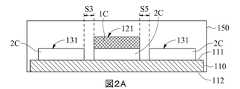
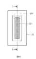
図1(A)を参照し、図1(A)は、本発明のマイクロバイオセンサーの第一実施形態の正面概略図である。本発明のマイクロバイオセンサー10は、基板110を含み、基板110は、表面111と、表面111に配置される第一作用電極120、第二作用電極130と、表面111、第一作用電極120及び第二作用電極130の一部を覆う絶縁層140とを有する。図1(B)を参照し、基板110の表面111上の第一作用電極120及び第二作用電極130の構成を明確に示すために、絶縁層140が除去されている。基板110は、表面111、反対側の表面112(図2(A)、図9(A)と図9(B)に示される)、第一端部113、第二端部114を含み、さらに信号出力領域115、感知領域116及びその上の絶縁領域117を限定する。信号出力領域115は、第一端部113に近い領域に配置され、感知領域116は、第二端部114に近い領域に配置され、絶縁領域117は、絶縁層140によってコーティングされ、信号出力領域115と感知領域116との間の領域に配置される。第一作用電極120及び第二作用電極130は、基板110の第一端部113から第二端部114まで延びる。第一作用電極120は、感知領域116に第一導電性材料1Cを有する第一感知部分121と、信号出力領域115にある第一信号出力部分122(図1(A)に示される)と、絶縁領域117の少なくとも一部によって部分的に覆われるように、第一感知部分121と第一信号出力部分122との間に配置される第一信号接続部分123(図1(B)に示される)とを含む。第二作用電極130は、感知領域116に第二導電性材料2Cを有する第二感知部分131と、信号出力領域115に第二信号出力部分132(図1(A)に示される)と、絶縁領域117の少なくとも一部によって覆われるように、第二感知部分131と第二信号出力部分132との間に配置される第二信号接続部分133(図1(B)に示される)とを含む。本発明の第二感知部分131は、第一感知部分121の少なくとも一つの側に隣接し、第二感知部分131の側は、第一感知部分121の少なくとも1つの側に沿って延びる。第一実施形態において、第二感知部分131は、第一感知部分121の三つの側に沿って延在して、U字形の感知部分を形成する。したがって、本発明の第一感知部分121及び第二感知部分131は、表面111を介してのみそれらの間の位置関係を維持する。本発明の第一感知部分121と第二感知部分131は互いに直接隣接しているため、電極や接続線などの中間体は存在しない。With reference to FIG. 1 (A), FIG. 1 (A) is a front schematic view of the first embodiment of the microbiosensor of the present invention. The
これらの構造を得るために、製造工程において、第二導電性材料2Cを、最初に基板110の表面111に形成し、図1(B)に示すようなパターンにパターン化することができる。具体的には、第二導電性材料2Cは二つの分離された領域に分割される。基板110の第一端部113から第二端部114で延在し、第二端部114で曲げられてU字形構造を形成する二つの領域のうちの一つは、第二作用電極130として事前設定され、基板110の第一端部113から第二端部114まで延在してU字形の構造によって囲まれる他の領域は、第一作用電極120として事前設定される。絶縁層140が基板110上に覆われ、信号出力領域115及び感知領域116を露光した後、第一導電性材料1Cは、感知領域116において第一作用電極120の第二導電性材料2C上に形成され、第一作用電極120の第一感知部分121の製造を終了する。しかしながら、図示していないが、第一導電性材料1Cは、感知領域116において第一作用電極120の第二導電性材料2Cの一部のみに形成することができる。したがって、図1の断面線A-A '、B-B'及びC-C 'に沿ったマイクロバイオセンサーの断面概略図は、それぞれ図2(A)、 図2(B)、 図2(C)に示す。図2(A)に示すように、本発明の第一実施形態の第一感知部分121は、基板の表面111に形成され、第一導電性材料1Cの上に配置される第二導電性材料2Cを有し、第二感知部分131は、第二導電性材料2Cを有する。図2(B)は、U字型の第二感知部分131の下部領域を示しており、したがって、基板110の表面111には第二導電性材料2Cのみが存在する。図2(C)に示されるように、第一導電性材料1Cは感知領域116のみに形成されるので、絶縁領域117に位置する第一作用電極120の部分は、第二導電性材料2Cのみを有し、絶縁層140によって覆われる。In order to obtain these structures, in the manufacturing process, the second
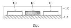
別の実施形態において、絶縁層140を形成するステップは、第一導電性材料1Cを形成した後に実行することができ、したがって、第一導電性材料1Cは、第一作用電極120のすべての第二導電性材料2Cに実質的に形成することができる。更に、パターニングステップの後の第二導電性材料2Cの位置、サイズ及び形状は、本発明の要求に応じて変更することができる。したがって、他の実施形態において、第二導電性材料2Cは、パターニングステップで定義されて、図1(B)に示されるようなパターンを表すことができるが、第一感知部分121が形成されると予想される領域で省略される。具体的には、第一作用電極120の第二導電性材料2Cは、信号出力領域115及び絶縁領域117においてのみ形成されるか、或いは、せいぜい部分的に感知領域116まで延びる。次に、第一導電性材料1Cが、第一感知部分121が形成されると予想される領域の表面111に直接形成される。第一導電性材料1Cは、第一作用電極120の他の部分(すなわち、第二導電性材料2C)に電気的に接続されて、第一作用電極120の配置を完成させる。この実施形態のマイクロバイオセンサー10の感知領域116の断面概略図は、図2(D)として示される。他の実施形態において、第一作用電極120が形成されると予想される領域内の第二導電性材料2Cは、パターニングステップで除去することができる。そのため、絶縁層140をコーティングする前に、第一導電性材料1Cを第一作用電極120に直接形成して、第一作用電極120を形成することができる。In another embodiment, the step of forming the insulating
本発明のマイクロバイオセンサー10において、感知領域116内の第二感知部分131と第一感知部分121との間の間隙は、0.2mm以下である。好ましくは、間隙は、0.01mm~0.2mmの範囲である。より好ましくは、間隙は、0.01mm~0.1mmの範囲である。更に好ましくは、間隙は、0.02mm~0.05mmの範囲である。具体的には、 図2(A)に示すように、第一実施形態において、第一感知部分121と第二感知部分131との間の間隙S3とS5は両方とも0.04mmである。In the
本発明において、第一導電性材料1Cは、炭素、白金、アルミニウム、ガリウム、金、インジウム、イリジウム、鉄、鉛、マグネシウム、ニッケル、モリブデン、オスミウム、パラジウム、ロジウム、銀、スズ、チタン、 亜鉛、シリコン、ジルコニウムのうちの1つ、それらの誘導体(合金、酸化物又は金属化合物など)、又はそれらの組み合わせであり得る。第二導電性材料2Cは、第一導電性材料1Cに例示された要素又はその誘導体であり得る。本発明の絶縁層140の材料は、絶縁効果を達成することができる任意の材料であり得る、例えばパリレン、ポリイミド、ポリジメチルシロキサン(PDMS)、液晶ポリマー材料(LCP)又はMicroChem, etc.のSU-8フォトレジストなどであるが、これらに限定されない。In the present invention, the first
図3(A)と図3(B)を参照し、図3(A)は、本発明のマイクロバイオセンサー10の第二実施形態の正面概略図であり、図3(B)は、絶縁層14が除去され、基板110の表面111上の第一作用電極120及び第二作用電極130の配置を明確に示している。第二実施形態において、第一作用電極120及び第二作用電極130は、基板110の第一端部113から第二端部114まで延びる。感知領域116内に配置され、第一導電性材料1Cによって覆われる第一作用電極120の一部は、第一感知部分121であり、感知領域116内に配置され、第二導電性材料2Cを有する第二作用電極130の一部は、第二感知部分131である(図3(A)に示す)。第二実施形態において、第二感知部分131は、第一感知部分121の片側に沿って曲がることなく延在し、その結果、第二感知部分131は、第一感知部分121の片側にのみ隣接している。したがって、図3(A)の断面線A~A 'に沿ったマイクロバイオセンサーの断面概略図は、図4に示されている。本発明の第二実施形態の第一感知部分121は、第二導電性材料2Cで覆われた第一導電性材料1Cを有し、第二感知部分131は、第二導電性材料2Cを有し、第一感知部分121の片側にのみ隣接している。With reference to FIGS. 3 (A) and 3 (B), FIG. 3 (A) is a front schematic view of the second embodiment of the
図5(A)を参照し、図5(A)は、本発明のマイクロバイオセンサーの第三実施形態の正面概略図である。第三実施形態において、マイクロバイオセンサー10は、二つの第二作用電極130を有する。第一作用電極120及び二つの第二作用電極130は、基板110の第一端部113から第二端部114まで延在し、二つの第二作用電極130は、それぞれ、第一作用電極120の二つの反対側に沿って延在する。感知領域116に配置され、第一導電性材料1Cによって覆われる第一作用電極120の部分は、第一感知部分121であり、感知領域116に配置され、第二導電性材料2Cを有する二つの第二作用電極130の部分は、第二感知部分131である。第三実施形態において、二つの第二感知部分131は、それぞれ、第一感知部分121の二つの反対側に隣接して配置される。したがって、図5(A)の断面線A~A 'に沿ったマイクロバイオセンサーの断面概略図は、図5(B)を示す。本発明の第三実施形態の第一感知部分121は、第二導電性材料2Cで覆われた第一導電層1Cを有し、二つの第二感知部分131は、第二導電性材料2Cを有し、それぞれ、第一感知部分121の二つの反対側にのみ隣接している。With reference to FIG. 5 (A), FIG. 5 (A) is a front schematic view of a third embodiment of the microbiosensor of the present invention. In a third embodiment, the
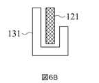
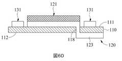
本発明の第一感知部分121及び第二感知部分131の構成は、第一から第三実施形態に記載されているが、他の構成もあり得る。例えば、第一実施形態において、第二感知部分131は、第一感知部分121の互いに接続された三つの側に沿って延在し、U字型の感知部分を形成する。しかしながら、変更された実施形態において、第二感知部分131の長さは、図6(A)に示すように、第一感知部分121の三つの側に沿って延びるように調整でき、或いは、第二感知部分131は、図6(B)に示すように、L字形の感知部分を形成するように、第一感知部分121の二つの隣接する側に沿って延びる。第一実施形態の別の変更された実施形態において、第一作用電極120の第一信号接続部分123は、基板110の貫通穴118を介して基板110の反対側の表面112に配置と延長され得る。したがって、第二感知部分131は、図6(C)~6(D)に示すように、第一感知部分121の四つの側を囲むことができる。第二実施形態であろうと第三実施形態であろうと、第二感知部分131の長さは、図7~8(C)に示すように変更され得る。したがって、前述の「第二感知部分131は、第一感知部分121の少なくとも一方の側に隣接する」という句は、具体的には、第一感知部分121の周辺の全体に対する、第二感知部分131に隣接する第一感知部分121の周辺部分の比率は、30%~100%の範囲であることを指す。The configurations of the
更に、図1(A)、2(A)、3(A)、4、5(A)と5(B)に示すように、本発明のマイクロバイオセンサー10は、化学試薬層150を更に含む。化学試薬層150は、少なくとも、第一感知部分121の第一導電性材料1Cを覆う。具体的には、本発明のマイクロバイオセンサー10の製造工程において、既に表面111及び/又は反対側の表面112に電極が配置されている基板110は、化学試薬を含む溶液に浸漬することができる。基板110の浸漬深さは、化学試薬層150が少なくとも一回にマイクロバイオセンサー10の感知領域116を覆うことができるように調整する。すなわち、化学試薬層150は、第一感知部分121の第一導電性材料1C及び第二感知部分131の第二導電性材料2Cの両方で覆うことができる。他の実施形態において、化学試薬層150は、図1(A)に示すように、絶縁領域117を更に覆うことができる。第一導電性材料1Cで覆われる化学試薬層150は、生体液中の標的分析物と反応して結果物を生成することができ、第一導電性材料1Cは、結果物と反応して、標的分析物に対応する生理信号を更に出力する。Further, as shown in FIGS. 1 (A), 2 (A), 3 (A), 4, 5 (A) and 5 (B), the
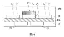
本発明に開示される二つの作用電極の構成は、二電極システム及び三電極システムに適用することができる。二電極システムにおいて、本発明のマイクロバイオセンサー10は、図9(A)に示されるように、基板110の反対側の表面112に配置される少なくとも一つの対電極160を更に含む。図9(A)は、マイクロバイオセンサーの感知領域の断面概略図である。対電極160は、第一作用電極120又は第二作用電極130と協働することができる。二電極システムにおける対電極160は、使用した材料に基づいて参照電極としても機能することができる。対電極160は、第一作用電極120及び/又は第二作用電極130に結合されている。他の実施形態において、対電極160は、基板110の表面111に配置され得る(図示されていない)。三電極システムにおいて、本発明のマイクロバイオセンサー10は、対電極160を除いて、図9(B)に示しように、参照電位を提供するために使用される参照電極170を更に含む。図9(B)は、マイクロバイオセンサー10の感知領域116の断面概略図である。具体的には、対電極160及び参照電極170は分離されており、電気的に接続されておらず、対電極160は、第一作用電極120及び/又は第二作用電極130に結合されている。対電極160及び参照電極170は、両方とも、基板110の表面111上に配置され得るか(図示されていない)、またはそれぞれ基板110の異なる表面に配置され得る。また、 図9(A)~9(B)に示すように、化学試薬層150は、対電極160及び/又は参照電極170上に実質的に覆われている。The configuration of the two working electrodes disclosed in the present invention can be applied to a two-electrode system and a three-electrode system. In a two-electrode system, the
本発明における「駆動」という用語は、一方の電極の電位を他方の電極の電位よりも高くする電圧を印加することを意味し、その結果、より高い電位を有する電極が酸化反応を開始することに留意されたい。したがって、第一作用電極120と対電極160との間の電位差が第一作用電極120を駆動させるものは第一作用電圧であり、第二作用電極130と対電極160との間の電位差が第二作用電極130を駆動させるものは第二作用電圧である。The term "driving" in the present invention means applying a voltage that makes the potential of one electrode higher than the potential of the other electrode, so that the electrode having the higher potential initiates the oxidation reaction. Please note. Therefore, it is the first working voltage that the potential difference between the first working
図10を参照し、本発明のマイクロバイオセンサー10の第一作用電極120は、生体液中の標的分析物の生理パラメータを測定するために使用される。マイクロバイオセンサー10の第一作用電極120が第一作用電圧によって駆動されると、第一感知部分は、測定範囲1Sを生成し、結果物に対して第一感度を有するので、第一導電性材料1Cは結果物と反応して電流信号を生成する。次に、電流信号は、信号接続部分123を介して第一作用電極120の信号出力部分122に送信され、電流信号の値は、結果物の濃度と比例関係を有し、結果として、生理パラメータに対応する生理信号が得られる。したがって、第一作用電極120が第一作用電圧によって駆動されると、結果物と反応して標的分析物の生理パラメータに対応する生理信号を出力する第一導電性材料1Cの動作が測定動作として定義される。しかしながら、生体液中には干渉物があり、第一導電性材料1Cが干渉物と反応して干渉電流信号を生成し、干渉電流信号と電流信号が一緒に出力されて生理信号が干渉される。With reference to FIG. 10, the first working
したがって、本発明のマイクロバイオセンサー10の第二作用電極130は、干渉物を消耗するために適用することができる。マイクロバイオセンサー10の第二作用電極130が第二作動電圧によって駆動されると、第二感知部分131の第二導電性材料2Cは、結果物に対して第二感度を有し、第二感知部分131のそれぞれは、干渉除去範囲2Sを生成する。第二感知部分131は第一感知部分121の非常に近くに配置されているため、干渉除去範囲2Sは、それぞれ、第一感知部分121の周辺に接触し、第一感知部分121の測定範囲1Sと少なくとも部分的に重なることができる。その結果、第二導電性材料2Cは、干渉物との酸化反応を受けることによって干渉物を直接且つ連続的に消耗し、干渉電流信号の生成を低減する。これにより、測定動作に対する干渉物の影響を低減することができる。したがって、第二作用電極130が第二作用電圧によって駆動されると、第二導電性材料2Cに生体内の干渉物を消耗させる動作は、干渉除去動作として定義される。Therefore, the second working
更に、第二作用電極130が第二作用電圧によって駆動されると、第二導電性材料2Cは、結果物と反応して別の電流信号を生成する。これは、標的分析物の生理パラメータを得るために第一作用電極120によって測定されるべき結果物を消耗する。そのため、実際に測定された生理パラメータが影響を受ける。したがって、一つの実施形態において、標的分析物がグルコースである場合、結果物は過酸化水素であり、生理パラメータはグルコース濃度であり、第一導電性材料1Cは、好ましくは、第一動作電圧によって駆動された後、過酸化水素に対して第一感度を有する材料であるべきだ。より好ましくは、第一導電性材料1Cは、金、白金、パラジウム、イリジウム、及びそれらの組み合わせからなる群から選択される。第二導電性材料2Cは、第一導電性材料1Cとは異なる。具体的には、第二導電性材料2Cは、好ましくは、第二作用電圧によって駆動された後、第一感度よりも低い過酸化水素に対する第二感度を有する材料であるべきだ。特に、第二導電性材料2Cは、第二作用電圧によって駆動された後、過酸化水素に対してほとんど感度がない、すなわち、第二感度がゼロに近いかゼロに等しい材料である。より具体的には、本発明の一つの実施形態において、第一導電性材料1Cは白金であり、第一作用電圧は、0.2ボルト(V)~0.8ボルト(V)の範囲であり、好ましくは、0.4ボルト(V)~0.7ボルト(V)の範囲であり、第二導電性材料2Cは炭素であり、第二作用電圧は、0.2ボルト(V)~0.8ボルト(V)の範囲であり、好ましくは、0.4ボルト(V)~0.7ボルト(V)の範囲である。本発明の別の実施形態において、第一導電性材料1Cは白金であり、第二導電性材料2Cは金である。前述の白金の形態は、白金金属、白金黒、白金ペースト、他の白金含有材料、又はそれらの組み合わせであり得ることに留意されたい。また、第一作用電圧の値は、第二作用電圧の値と同じであり得るが、本発明はそれに限定されない。Further, when the second working
図11と図12を参照し、本発明のマイクロバイオセンサー10を操作する方法を更に説明する。 図11は、本発明の図9(A)に示すように、マイクロバイオセンサー10の電圧を制御し、電流を測定する回路の例である。図12は、本発明のマイクロバイオセンサー10の測定中に生じる干渉を低減するための方法のフローチャートである。図11において、電流感知ユニット201は、マイクロバイオセンサー10の第一作用電極120に接続され、別の電流感知ユニット202は、対電極160に接続される。電流感知ユニット201と202は、それぞれ、第一作用電極120及び対電極160からの電流信号i1とi3を測定し、i2は、第二作用電極130からの電流信号であり、別の電流感知ユニット(図示していない)によって測定することができる。この例において、第一作用電圧は、第一作用電極120の電位V1と対電極160の電位V3との間の差であり、第二作用電圧は、第二作用電極130の電位V2と対電極160の電位V3との間の差である。スイッチS1とS2は、それぞれ、第一作用電極120及び第二作用電極130をフローティングに設定することを可能にする。本発明の測定干渉を低減するための方法は、図12に示され、マイクロバイオセンサーを提供するステップS101と、干渉除去動作を実行するステップS102、測定動作を実行するステップS103を含む。干渉除去動作と測定動作の間には時間関係があり、可能な時系列はそれぞれ次のとおりである。A method of operating the
第一時間関係:本発明のマイクロバイオセンサーは、例えば二週間の期間Tの間に測定を実行し、期間Tは、複数の第一サブタイム(T1)ゾーン及び/又は複数の第二サブタイム(T2)ゾーンを含む。干渉除去動作は各T1ゾーンで実行され、測定動作は各T2ゾーンで実行される。干渉除去動作と測定動作を交互に行う。即ち、第一時間関係は、順次に、第一T1ゾーンで第一干渉除去動作を実行して干渉物を消耗する。第一T2ゾーンで第一測定動作を実行して、当時の生理パラメータに対応する第一生理信号を出力する。第二T1ゾーンで第二干渉除去動作を実行して干渉物を消耗する。第二T2ゾーンで第二測定動作を実行して、当時の生理パラメータに対応する第二生理信号を出力する。以下同様に、期間T中の各T2ゾーンにおける生理パラメータの値データを取得する。図13(A)~13(C)に示すように、図の水平軸と垂直軸はそれぞれ時間と電流を表している。ここで、測定動作の線は、第一作用電圧の印加と除去を示し、干渉除去作用のもう一方の線は、第二作用電圧の印加と除去を示す。第一時間関係において、T1ゾーンとT2ゾーンは少なくとも部分的に重ねることができ(図13(A)に示す)、T1ゾーンとT2ゾーンを互いに分離することができ(図13(B)に示す)、又はT1ゾーンとT2ゾーンが完全に重なっている。すなわち、測定動作と干渉除去動作を同時に実行することができる(図13(C)に示す)。期間Tにおいて、第二作用電圧を任意の二つのT1ゾーン間で除去して、干渉除去動作を停止し、二つのT1ゾーンを分離することができ、第一作用電圧を任意の二つのT2ゾーン間で除去して、測定動作を停止し、二つのT1ゾーンを分離することができる。第一時間関係において、T1ゾーンの期間は、電流信号が結果物の濃度に対応し、生理パラメータと比例関係を持つように調整される。効果的な干渉消耗を達成するために、T1ゾーンの期間は、T2ゾーンの期間と同じにする、又はT2ゾーンの期間より長くなる。First time relationship: The microbiosensor of the invention performs measurements during, for example, a two-week period T, where period T is a plurality of first subtime (T1) zones and / or multiple second subtime. (T2) Includes zone. The interference elimination operation is performed in each T1 zone, and the measurement operation is performed in each T2 zone. Interference removal operation and measurement operation are performed alternately. That is, in the first time relationship, the first interference removing operation is sequentially executed in the first T1 zone to consume the interfering material. The first measurement operation is executed in the first T2 zone, and the first physiological signal corresponding to the physiological parameters at that time is output. The second interference removing operation is executed in the second T1 zone to consume the interfering material. The second measurement operation is executed in the second T2 zone, and the second physiological signal corresponding to the physiological parameter at that time is output. Similarly, the value data of the physiological parameter in each T2 zone during the period T is acquired. As shown in FIGS. 13 (A) to 13 (C), the horizontal axis and the vertical axis in the figure represent time and current, respectively. Here, the line of measurement operation indicates the application and removal of the first acting voltage, and the other line of the interference elimination action indicates the application and removal of the second acting voltage. In the first time relationship, the T1 zone and the T2 zone can be at least partially overlapped (shown in FIG. 13 (A)), and the T1 zone and the T2 zone can be separated from each other (shown in FIG. 13 (B)). ), Or the T1 zone and the T2 zone completely overlap. That is, the measurement operation and the interference removal operation can be executed at the same time (shown in FIG. 13C). During period T, the second working voltage can be removed between any two T1 zones to stop the interference elimination operation, the two T1 zones can be separated, and the first working voltage can be taken from any two T2 zones. It can be removed between to stop the measurement operation and separate the two T1 zones. In the first time relationship, the period of the T1 zone is adjusted so that the current signal corresponds to the concentration of the product and is proportional to the physiological parameters. In order to achieve effective coherent depletion, the duration of the T1 zone should be the same as the duration of the T2 zone or longer than the duration of the T2 zone.
更に、図13(A)~13(B)に示すように、第一干渉除去動作は、好ましくは、第一測定動作よりも早く、又は同時に実行される。具体的には、複数の測定動作がある場合、干渉除去動作は少なくとも1回実行され、好ましくは、干渉除去動作の開始は、複数の測定動作の第一測定動作の開始までに行われる。Further, as shown in FIGS. 13 (A) to 13 (B), the first interference removing operation is preferably executed earlier than or simultaneously with the first measurement operation. Specifically, when there are a plurality of measurement operations, the interference elimination operation is executed at least once, and preferably, the interference elimination operation is started by the start of the first measurement operation of the plurality of measurement operations.
第二時間関係:本発明のマイクロバイオセンサーは、例えば二週間の期間Tの間に測定を実行し、期間Tは、複数のサブタイムゾーンを含む。干渉除去動作は期間T全体で実行され、測定動作は各サブタイムゾーンで実行される。測定動作は間隔を置いて実行される。即ち、図14を参照し、第二時間関係は、期間T全体で第一干渉除去動作を継続的に実行して、期間Tの終わりまで干渉物を消耗する。干渉除去動作を実行し、第一サブタイムゾーンで第一測定動作を実行して、当時の生理パラメータに対応する第一生理信号を出力する。第二サブタイムゾーンで第二測定動作を実行して、当時の生理パラメータに対応する第二生理信号を出力する。以下同様に、期間T中のすべての異なるサブタイムゾーンにおける生理パラメータの値データを取得する。二つの隣接するサブタイムゾーンの間には時間間隔がある。期間Tにおいて、第一作用電圧を任意の二つのサブタイムゾーン間で除去して、測定動作を停止し、二つのサブタイムゾーンを分離することができる。第二時間関係において、各サブタイムゾーンの期間は同じでも異なっていてもかまわない。各サブタイムゾーンの期間は、電流信号が結果物の濃度に対応し、生理パラメータと比例関係を持つように調整される。Second time relationship: The microbiosensor of the present invention performs measurements during a period T of, for example, two weeks, where the period T comprises a plurality of subtime zones. The decoupling operation is performed for the entire period T and the measurement operation is performed in each subtime zone. Measurement operations are performed at intervals. That is, with reference to FIG. 14, the second time relationship continuously executes the first interference elimination operation throughout the period T and consumes the interfering material until the end of the period T. The interference elimination operation is executed, the first measurement operation is executed in the first subtime zone, and the first physiological signal corresponding to the physiological parameters at that time is output. The second measurement operation is executed in the second sub time zone, and the second physiological signal corresponding to the physiological parameter at that time is output. Similarly, the value data of the physiological parameters in all the different sub-time zones during the period T are acquired. There is a time interval between two adjacent subtime zones. In period T, the first working voltage can be removed between any two subtime zones to stop the measurement operation and separate the two subtime zones. In the second time relationship, the period of each sub time zone may be the same or different. The duration of each subtime zone is adjusted so that the current signal corresponds to the concentration of the product and is proportional to the physiological parameters.
第三時間関係:図示していないが、第三時間関係と第二時間関係との違いは、第三時間関係が期間T全体で測定動作を継続し、各サブタイムゾーンで干渉除去動作を実行することである。即ち、 干渉除去動作を交互に実行する。Third time relationship: Although not shown, the difference between the third time relationship and the second time relationship is that the third time relationship continues the measurement operation for the entire period T and performs the interference elimination operation in each subtime zone. It is to be. That is, the interference elimination operations are executed alternately.
第四時間関係:図15を参照し、本発明のマイクロバイオセンサーは、例えば二週間の期間Tの間に測定を実行する。干渉除去動作は、期間T全体にわたって継続的に実行され、同時に、測定動作も、期間Tの終わりまで継続的に実行されて、干渉物を継続的に消耗し、生理パラメータを測定する。Fourth time relationship: See FIG. 15, the microbiosensors of the invention perform measurements, eg, during a two-week period T. The interference elimination operation is continuously performed throughout the period T, and at the same time, the measurement operation is also continuously performed until the end of the period T to continuously consume the interfering material and measure the physiological parameters.
[生体外での干渉除去試験]
試験例
この試験例では、二つの作用電極を有する第一実施形態のマイクロバイオセンサーが使用され、第一感知部分はプラチナブラックでコーティングされた炭素電極であり、第二感知部分は炭素電極であり、第一作用電圧は0.5Vであり、第二作用電圧は0.5Vであり、干渉物はアセトアミノフェンである。[In vitro interference removal test]
Test Example In this test example, the microbiosensor of the first embodiment having two working electrodes is used, the first sensing part is a carbon electrode coated with platinum black, and the second sensing part is a carbon electrode. , The first working voltage is 0.5V, the second working voltage is 0.5V and the interfering substance is acetaminophen.
比較試験例
この比較試験例では、比較試験例で使用されるマイクロバイオセンサーは、試験例と同じであるが、第二作用電圧は提供されていない。第二作用電圧が提供されないので、第二感知部分131は駆動されず、したがって、図16に示されるように、第一感知部分の測定範囲1Sのみが存在する。Comparative Test Example In this comparative test example, the microbiosensor used in the comparative test example is the same as that of the test example, but the second working voltage is not provided. Since the second acting voltage is not provided, the
本発明のマイクロバイオセンサーを用いた生体外での干渉除去試験の方法は以下の通りである。試験例及び比較試験例のマイクロバイオセンサーを、異なる期間で、リン酸緩衝生理食塩水(PBS)溶液、100mg/dLのグルコース溶液、40mg/dLのグルコース溶液、100mg/dLのグルコース溶液、300mg/dLのグルコース、500mg/dLのグルコース、100mg/dLグルコース、2.5mg/dLのアセトアミノフェンを含む100mg/dLのグルコース、100mg/dLのグルコース、5.0mg/dLのアセトアミノフェンを含む100mg/dLのグルコースに順次浸漬する(P1からP9)。結果を図17に示す。第一感知部分121から測定された電流信号は、曲線C1として示され、第二感知部分131から測定された電流信号は、試験例において曲線C2として示され、第一感知部分121から測定された電流信号は、比較試験例において曲線C3として示される。The method of the in vitro interference elimination test using the microbiosensor of the present invention is as follows. The microbiosensors of the test examples and comparative test examples were used in different periods for a phosphate buffered physiological saline (PBS) solution, a 100 mg / dL glucose solution, a 40 mg / dL glucose solution, a 100 mg / dL glucose solution, and a 300 mg / dL. dL glucose, 500 mg / dL glucose, 100 mg / dL glucose, 100 mg / dL glucose containing 2.5 mg / dL acetaminophen, 100 mg / dL glucose, 100 mg containing 5.0 mg / dL acetaminophen Immerse in / dL glucose sequentially (P1 to P9). The results are shown in FIG. The current signal measured from the
図16の時間期間P1~P5から見ることができる。試験例又は比較試験例に関係なく、第一感知部分は、異なる期間における異なるグルコース濃度に従って、異なる強度の電流信号を生成する。つまり、第一感知部分の電流信号と生理パラメータの間には比例関係がある。ただし、第二感知部分から生成される電流信号はない。これは、酵素によって触媒されるグルコースに由来する副産物である過酸化水素に対する第二感知部分の活性又は感度が非常に低く、ゼロに近いかゼロに等しいことを表す。更に、曲線C3から、比較試験例のマイクロバイオセンサーを、期間P7で2.5mg/dLのアセトアミノフェンを含む100mg/dLのグルコース溶液に浸漬すると、期間P3で測定された現在の信号と比較して、期間P7で第一感知部分121によって測定された電流信号は、明らかに干渉物の影響を受けて高く浮き、測定干渉のレベルは、マイクロバイオセンサーが期間P9で5mg/dLのアセトアミノフェンを含む100mg/dLのグルコース溶液に浸されたときに更に明確になる。逆に、曲線C1及び曲線C2から、試験例のマイクロバイオセンサーを、期間P7で2.5mg/dLのアセトアミノフェンを含む100mg/dLのグルコース溶液に浸漬すると、期間P7での電流信号は、期間P3の電流信号と一致している。具体的には、第二作用電極130を第二作用電圧で駆動して干渉除去動作を行うと、アセトアミノフェンの濃度を上げても、第一感知部分121がアセトアミノフェンの影響を受けるレベルを下げることができる。他方、第二作用電極130の第二感知部分131はアセトアミノフェンを消耗するために使用されるので、PBS溶液及びグルコース溶液で電流信号が生成されないが、アセトアミノフェンがある場合には電流信号が生成される。したがって、測定環境(すなわち、測定範囲)にアセトアミノフェンが存在する場合、第二感知部分131は、アセトアミノフェンを消耗して、アセトアミノフェンによって干渉される第一感知部分の測定を減らすことができ、これにより、マイクロバイオセンサーは、より正確な生理パラメータを測定することができる。It can be seen from the time period P1 to P5 of FIG. Regardless of the test example or the comparative test example, the first sensing portion produces different intensity current signals according to different glucose concentrations in different time periods. That is, there is a proportional relationship between the current signal of the first sensing portion and the physiological parameters. However, there is no current signal generated from the second sensing portion. This indicates that the activity or sensitivity of the second sensing moiety to hydrogen peroxide, a by-product derived from glucose catalyzed by the enzyme, is very low, near or equal to zero. Further, from curve C3, the microbiosensor of the comparative test example was immersed in a 100 mg / dL glucose solution containing 2.5 mg / dL of acetaminophen during period P7 and compared with the current signal measured during period P3. Then, the current signal measured by the
生体内での干渉除去試験
生体内での干渉除去試験では、本発明の二つの作用電極を有する第一実施形態のマイクロバイオセンサーが使用され、第一感知部分は白金黒でコーティングされた炭素電極であり、第二感知部分は炭素電極であり、第一作用電圧は0.5Vであり、第二作用電圧は0.5Vである。マイクロバイオセンサーを人の皮膚の下に埋め込んで間質液中のグルコース濃度を継続的に監視し、86時間目にアセトアミノフェンを主成分とするパナドール1gを投与する。干渉物除去メカニズムがある場合とない場合のデータが測定され、従来の血糖値計で測定されたデータと比較される。結果を図18(A)~18(B)に示す。図18(A)は、干渉物除去メカニズムのない測定曲線であり、図18(A)は、干渉物除去メカニズムを有しない測定曲線であり、図18(B)は、干渉物除去メカニズムを有する測定曲線である。In-vivo interference elimination test In the in-vivo interference elimination test, the microbiosensor of the first embodiment having the two working electrodes of the present invention is used, and the first sensing portion is a carbon electrode coated with platinum black. The second sensing portion is a carbon electrode, the first working voltage is 0.5V, and the second working voltage is 0.5V. A microbiosensor is implanted under the human skin to continuously monitor the glucose concentration in the interstitial fluid, and at 86 hours, 1 g of panador containing acetaminophen as a main component is administered. Data with and without an interferometer removal mechanism are measured and compared to data measured with a conventional glucose meter. The results are shown in FIGS. 18 (A) to 18 (B). FIG. 18 (A) is a measurement curve without an interfering substance removing mechanism, FIG. 18 (A) is a measuring curve without an interfering substance removing mechanism, and FIG. 18 (B) has an interfering substance removing mechanism. It is a measurement curve.
図18(A)~18(B)において、黒い点は従来の血糖値計によって測定された値であり、点線は本発明のマイクロバイオセンサーの第一作用電極の測定曲線であり、実線は本発明のマイクロバイオセンサーの第二作用電極の測定曲線である。図18(A)から見ることができる。図18(A)において、干渉除去動作が活性化されない場合、本発明のマイクロバイオセンサーの第一作用電極によって測定される値が、約90~96時間(すなわち、1gのパナドールが投与された4~6時間後)に増加することを示す。それどころか、図18(B)から見ることができる。図18(B)において、干渉除去動作が活性化されると、本発明のマイクロバイオセンサーの第二感知部分は、対応する電流信号を測定し、第一作用電極によって測定された値は増加せず、従来の血糖値計を使用して測定値と一致させることができる。In FIGS. 18A to 18B, the black dots are the values measured by the conventional glucose meter, the dotted lines are the measurement curves of the first working electrode of the microbiosensor of the present invention, and the solid lines are the present. It is a measurement curve of the 2nd working electrode of the microbiosensor of the invention. It can be seen from FIG. 18 (A). In FIG. 18 (A), when the interference elimination operation is not activated, the value measured by the first working electrode of the microbiosensor of the present invention is about 90-96 hours (ie, 1 g of panador was administered 4). It is shown that it increases after ~ 6 hours). On the contrary, it can be seen from FIG. 18 (B). In FIG. 18B, when the interference elimination operation is activated, the second sensing portion of the microbiosensor of the present invention measures the corresponding current signal and the value measured by the first acting electrode increases. Instead, it can be matched to the measured value using a conventional glucose meter.
また、マイクロバイオセンサーの干渉除去機能を作動させた場合、薬物干渉のない期間の平均誤差値は0.1mg/dLとなり、薬物干渉のある期間の平均誤差値は-2.1mg/dLであり、合計誤差値は-1.1mg/dLであり、薬物干渉のある期間中の平均絶対相対差(MARD)は4.6である。マイクロバイオセンサーの干渉除去機能が作動していない場合、薬物干渉がない期間の平均誤差値は-0.2mg/dL、薬物干渉がある期間の平均誤差値は12.6mg/dL、合計誤差値は6.7mg/dLであり、薬物干渉のある期間の平均絶対相対差(MARD)は10.6である。第二作用電極130の第二感知部分131の干渉除去動作は、実際に、第一感知部分121によって測定された生理信号に対する干渉物の干渉を特定の許容範囲(20%、より具体的には10%など)以下に低減できることが分かる。要約すると、第二感知部分が第一感知部分の少なくとも一つの側に隣接して配置されるマイクロバイオセンサーを使用する本発明は、第二感知部分が第一感知部分の周りの干渉物を直接且つ継続的に消耗し、第一感知部分での干渉物の測定干渉を低減して、より正確なデータを取得する。When the interference elimination function of the microbiosensor is activated, the average error value during the period without drug interference is 0.1 mg / dL, and the average error value during the period with drug interference is -2.1 mg / dL. , The total error value is -1.1 mg / dL, and the mean absolute relative difference (MARD) during the period of drug interference is 4.6. When the interference elimination function of the microbiosensor is not activated, the average error value during the period without drug interference is -0.2 mg / dL, the average error value during the period with drug interference is 12.6 mg / dL, and the total error value. Is 6.7 mg / dL and the mean absolute relative difference (MARD) for a period of drug interference is 10.6. The interference elimination operation of the
以上、本発明を実施の形態を用いて説明したが、本発明の技術的範囲は上記実施の形態に記載の範囲には限定されない。上記実施の形態に、多様な変更または改良を加え得ることが当業者に明らかである。その様な変更または改良を加えた形態も本発明の技術的範囲に含まれ得ることが、特許請求の範囲の記載から明らかである。Although the present invention has been described above using the embodiments, the technical scope of the present invention is not limited to the scope described in the above embodiments. It will be apparent to those skilled in the art that various changes or improvements can be made to the above embodiments. It is clear from the description of the claims that the form with such changes or improvements may be included in the technical scope of the present invention.
第一導電性材料1C
測定範囲1S
第二導電性材料2C
干渉除去範囲2S
マイクロバイオセンサー10
基板110
表面111、112
第一端部113
第二端部114
信号出力領域115
感知領域116
絶縁領域117
第一作用電極120
第一感知部分121
第一信号出力部分122
第一信号接続部分123
第二作用電極130
第二感知部分131
第二信号出力部分132
絶縁層140
化学試薬層150
対電極160
参照電極170
電流感知ユニット201、202
電流信号i1、i3
スイッチS1、S2
間隙S3、S5
電位V1、V2、V3First
Measuring
Second
First working
First sensing
First
First
Second working
Second
Current signals i1, i3
Switches S1, S2
Gap S3, S5
Potentials V1, V2, V3
Claims (13)
Translated fromJapanese(a)第一作用電極、少なくとも一つの第二作用電極及び化学試薬を含むマイクロバイオセンサーを提供するステップであって、前記第一作用電極が第一感知部分を有し、前記第二作用電極が第二感知部分を有し、前記化学試薬が前記生体液中の前記標的分析物と反応して結果物を生成するように、前記第一感知部分の少なくとも一部を覆う前記ステップと、
(b)第一T1ゾーンで第一干渉除去動作を実行するステップであって、第二感知部分が、第二作用電圧によって駆動されて、前記生体液中の少なくとも一つの干渉物を消耗する前記ステップと、
(c)第一T2ゾーンで第一測定動作を実行するステップであって、前記第一感知部分は、第一作用電圧によって駆動され、前記結果物と反応して、当時の生理パラメータに対応する第一生理信号を出力する前記ステップと、
(d)第二T1ゾーンで第二干渉除去動作を実行するステップであって、前記第二感知部分は、第二作用電圧によって駆動されて、前記生体液中の前記少なくとも一つの干渉物を消耗する前記ステップと、
(e)第二T2ゾーンで第二測定動作を実行するステップであって、前記第一感知部分は、前記第一作用電圧によって駆動され、前記結果物と反応して、前記当時の生理パラメータに対応する第二生理信号を出力する前記ステップと、
(f)ステップ(b)からステップ(e)を繰り返し実行して、前記期間中のそれぞれのT2ゾーンの生理パラメータの値データを取得するステップと、を備え、
それぞれの前記第一T1ゾーンがそれぞれの前記T2ゾーンよりも早く開始することを特徴とする方法。While using a microbiosensor to measure physiological parameters representing the target analyte in body fluid during a period comprising at least one first subtime (T1) zone and / or second subtime (T2) zone. A method for reducing measurement interference of the target analyte.
(A) A step of providing a microbiosensor comprising a first working electrode, at least one second working electrode and a chemical reagent, wherein the first working electrode has a first sensing portion and the second working electrode. And the step covering at least a portion of the first sensing portion such that the chemical reagent reacts with the target analyte in the biological fluid to produce a product product.
(B) The step of executing the first interference elimination operation in the first T1 zone, wherein the second sensing portion is driven by the second acting voltage and consumes at least one interference substance in the biological fluid. Steps and
(C) In the step of executing the first measurement operation in the first T2 zone, the first sensing portion is driven by the first acting voltage and reacts with the result to correspond to the physiological parameters at that time. The step of outputting the first physiological signal and
(D) In the step of executing the second interference removing operation in the second T1 zone, the second sensing portion is driven by the second acting voltage and consumes the at least one interfering substance in the biological fluid. With the above steps
(E) In the step of executing the second measurement operation in the second T2 zone, the first sensing portion is driven by the first acting voltage and reacts with the result to obtain the physiological parameters at that time. The step of outputting the corresponding second physiological signal and
(F) A step of repeatedly executing steps (e) from step (b) to acquire value data of physiological parameters of each T2 zone during the period is provided.
A method characterized in thateach said first T1 zone starts earlier than each said T2 zone .
ステップ(c)と(d)又はステップ(e)と(f)との間に、前記第一作用電圧を除去して、前記第一測定動作又は前記第二測定動作を停止するステップを更に備える、ことを特徴とする請求項1に記載の方法。Between steps (b) and (c) or steps (d) and (e), a step of removing the second acting voltage to stop the first interference removing operation or the second interference removing operation is performed. Further preparation,
Further provided between steps (c) and (d) or steps (e) and (f) is a step of removing the first acting voltage to stop the first measurement operation or the second measurement operation. The method according to claim 1, wherein the method is characterized by the above.
前記第一生理信号及び前記第二生理信号に対する前記少なくとも一つの干渉物の干渉を特定の許容範囲以下になるように低減させるために、ステップ(b)とステップ(d)を実行する、ことを特徴とする請求項1に記載の方法。Each T1 zone and each T2 zone completely overlap,
Performing steps (b) and (d) to reduce the interference of the first physiological signal and the at least one interfering substance with respect to the second physiological signal to be less than a certain allowable range. The method according to claim 1.
前記第一感知部分は、前記結果物に対して第一感度を有し、前記第一感知部分は、前記第一作用電圧によって駆動され、
前記第二感知部分は、前記結果物に対する前記第一感度よりも小さい第二感度を有し、前記第二感知部分は、前記第二作用電圧によって駆動され、
前記第一感知部分の表面材料は、白金(Pt)、イリジウム(Ir)、パラジウム(Pd)、金(Au)、それらの誘導体、及びそれらの組み合わせからなる群から選択されるものであり、
前記第一感知部分の表面材料は、0.2ボルト~0.8ボルトの前記第一作用電圧を有する白金である場合、前記第二感知部分の表面材料は、0.2ボルト~0.8ボルトの前記第二作用電圧を有する炭素である、ことを特徴とする請求項1に記載の方法。The surface material of the first sensing portion is different from the surface material of the second sensing portion.
The first sensing portion has first sensitivity to the result product, and the first sensing portion is driven by the first acting voltage.
The second sensing portion has a second sensitivity less than the first sensitivity to the result product, and the second sensing portion is driven by the second acting voltage.
The surface material of the first sensing portion is selected from the group consisting of platinum (Pt), iridium (Ir), palladium (Pd), gold (Au), derivatives thereof, and combinations thereof.
When the surface material of the first sensing portion is platinum having the first acting voltage of 0.2V to 0.8V, the surface material of the second sensing portion is 0.2V to 0.8V. The method according to claim 1, wherein the carbon is carbon having the second acting voltage of the bolt.
前記第二作用電極の前記第二感知部分は、前記第二作用電圧によって駆動されて、干渉除去範囲を形成し、
前記干渉除去範囲は、前記第一感知部分の周囲に接触し、少なくとも部分的に前記測定範囲と重なる、ことを特徴とする請求項1に記載の方法。The first sensing portion of the first working electrode is driven by the first working voltage to form a measurement range.
The second sensing portion of the second working electrode is driven by the second working voltage to form an interference elimination range.
The method according to claim 1, wherein the interference removing range is in contact with the periphery of the first sensing portion and at least partially overlaps with the measurement range.
前記第一作用電極及び前記第二作用電極は、前記基板の同じ表面上に配置され、
前記第二感知部分は前記第一感知部分に隣接して配置され、
前記第二感知部分は、前記第一感知部分の少なくとも一つの側に間隙を隣接して配置され、
前記間隙は、0.2mm以下であり、
前記第二感知部分は、前記第一感知部分の周辺の少なくとも一部に沿って延在し、前記第一感知部分の前記周辺の前記少なくとも一部から離間されており、
前記第一感知部分の前記周辺の全体に対する前記第一感知部分の前記周辺の前記一部の比率は、30%~100%の範囲である、ことを特徴とする請求項1に記載の方法。The microbiosensor further comprises a substrate and includes.
The first working electrode and the second working electrode are arranged on the same surface of the substrate.
The second sensing portion is arranged adjacent to the first sensing portion.
The second sensing portion is arranged adjacent to a gap on at least one side of the first sensing portion.
The gap is 0.2 mm or less, and the gap is 0.2 mm or less.
The second sensing portion extends along at least a portion of the periphery of the first sensing portion and is separated from at least a portion of the periphery of the first sensing portion.
The method according to claim 1, wherein the ratio of the portion of the periphery of the first sensing portion to the entire periphery of the first sensing portion is in the range of 30% to 100%.
(a)第一作用電極、少なくとも一つの第二作用電極及び化学試薬を含むマイクロバイオセンサーを提供するステップであって、前記第一作用電極が第一感知部分を有し、前記第二作用電極が第二感知部分を有し、前記化学試薬が前記生体液中の前記標的分析物と反応して結果物を生成するように、前記第一感知部分の少なくとも一部を覆う前記ステップと、
(b)前記期間中に干渉除去動作を実行するステップであって、前記第二感知部分が、第二作用電圧によって駆動されて、前記期間の終わりまで前記生体液中の少なくとも一つの干渉物を消耗する前記ステップと、
(c)前記期間の第一サブタイムゾーンで第一測定動作を実行することで、前記第一感知部分が前記第一作用電圧によって駆動され、前記結果物と反応して、前記当時の生理パラメータに対応する第一生理信号を出力するステップと、
(d)前記期間の第二サブタイムゾーンで第二測定動作を実行することで、前記第一感知部分が前記第一作用電圧によって駆動され、前記結果物と反応して、前記当時の生理パラメータに対応する第二生理信号を出力するステップと、
(e)ステップ(c)からステップ(d)を繰り返し実行して、前記期間中のすべての異なるサブタイムゾーンでの生理パラメータの値データを取得するステップと、を備えることを特徴とする方法。A method for reducing measurement interference of said target analyte while measuring physiological parameters representing the target analyte in body fluid during the period using a microbiosensor.
(A) A step of providing a microbiosensor comprising a first working electrode, at least one second working electrode and a chemical reagent, wherein the first working electrode has a first sensing portion and the second working electrode. And the step covering at least a portion of the first sensing portion such that the chemical reagent reacts with the target analyte in the biological fluid to produce a product product.
(B) In the step of performing the interference elimination operation during the period, the second sensing portion is driven by the second acting voltage to dissipate at least one interfering substance in the body fluid until the end of the period. The steps that are exhausted and
(C) By performing the first measurement operation in the first sub-time zone of the period, the first sensing portion is driven by the first acting voltage and reacts with the result to cause the physiological parameters at that time. And the step to output the first physiological signal corresponding to
(D) By executing the second measurement operation in the second sub-time zone of the period, the first sensing portion is driven by the first acting voltage and reacts with the result to cause the physiological parameters at that time. And the step to output the second physiological signal corresponding to
(E) A method comprising repeatedly executing steps (c) to (d) to acquire value data of physiological parameters in all different sub-time zones during the period.
前記第一感知部分は、前記結果物に対して第一感度を有し、前記第一感知部分は、前記第一作用電圧によって駆動され、
前記第二感知部分は、前記結果物に対する前記第一感度よりも小さい第二感度を有し、前記第二感知部分は、前記第二作用電圧によって駆動される、ことを特徴とする請求項10に記載の方法。The surface material of the first sensing portion is different from the surface material of the second sensing portion.
The first sensing portion has first sensitivity to the result product, and the first sensing portion is driven by the first acting voltage.
10. The second sensing portion has a second sensitivity smaller than the first sensitivity to the result product, and the second sensing portion is driven by the second acting voltage. The method described in.
前記第一作用電極及び前記第二作用電極は、前記基板の同じ表面上に配置され、
前記第二感知部分は前記第一感知部分に隣接して配置され、
前記第二感知部分は、前記第一感知部分の少なくとも一つの側に間隙を隣接して配置され、
前記間隙は、0.2mm以下である、ことを特徴とする請求項10に記載の方法。The microbiosensor further comprises a substrate and includes.
The first working electrode and the second working electrode are arranged on the same surface of the substrate.
The second sensing portion is arranged adjacent to the first sensing portion.
The second sensing portion is arranged adjacent to a gap on at least one side of the first sensing portion.
The method according to claim 10, wherein the gap is 0.2 mm or less.
Applications Claiming Priority (4)
| Application Number | Priority Date | Filing Date | Title |
|---|---|---|---|
| US201962882162P | 2019-08-02 | 2019-08-02 | |
| US62/882,162 | 2019-08-02 | ||
| US202062988549P | 2020-03-12 | 2020-03-12 | |
| US62/988,549 | 2020-03-12 |
Publications (2)
| Publication Number | Publication Date |
|---|---|
| JP2021047172A JP2021047172A (en) | 2021-03-25 |
| JP7089559B2true JP7089559B2 (en) | 2022-06-22 |
Family
ID=71943924
Family Applications (6)
| Application Number | Title | Priority Date | Filing Date |
|---|---|---|---|
| JP2020131742AActiveJP7143373B2 (en) | 2019-08-02 | 2020-08-03 | implantable micro biosensor |
| JP2020131753AActiveJP7162642B2 (en) | 2019-08-02 | 2020-08-03 | Micro biosensor and its measurement method |
| JP2020131741AActiveJP7198243B2 (en) | 2019-08-02 | 2020-08-03 | IMPLANTABLE MICRO-BIOSENSOR AND METHOD OF OPERATION THEREOF |
| JP2020131642AActiveJP7089559B2 (en) | 2019-08-02 | 2020-08-03 | Methods for reducing measurement interference with microbiosensors |
| JP2020131579AActiveJP7104109B2 (en) | 2019-08-02 | 2020-08-03 | Microbiosensors and methods for using them to reduce measurement interference |
| JP2022109556AActiveJP7595045B2 (en) | 2019-08-02 | 2022-07-07 | Microbiosensor and method for using same to reduce measurement interference - Patents.com |
Family Applications Before (3)
| Application Number | Title | Priority Date | Filing Date |
|---|---|---|---|
| JP2020131742AActiveJP7143373B2 (en) | 2019-08-02 | 2020-08-03 | implantable micro biosensor |
| JP2020131753AActiveJP7162642B2 (en) | 2019-08-02 | 2020-08-03 | Micro biosensor and its measurement method |
| JP2020131741AActiveJP7198243B2 (en) | 2019-08-02 | 2020-08-03 | IMPLANTABLE MICRO-BIOSENSOR AND METHOD OF OPERATION THEREOF |
Family Applications After (2)
| Application Number | Title | Priority Date | Filing Date |
|---|---|---|---|
| JP2020131579AActiveJP7104109B2 (en) | 2019-08-02 | 2020-08-03 | Microbiosensors and methods for using them to reduce measurement interference |
| JP2022109556AActiveJP7595045B2 (en) | 2019-08-02 | 2022-07-07 | Microbiosensor and method for using same to reduce measurement interference - Patents.com |
Country Status (9)
| Country | Link |
|---|---|
| US (11) | US12023150B2 (en) |
| EP (10) | EP3771410A1 (en) |
| JP (6) | JP7143373B2 (en) |
| KR (5) | KR102506277B1 (en) |
| CN (11) | CN112294320B (en) |
| AU (5) | AU2020210303B2 (en) |
| CA (5) | CA3104900A1 (en) |
| TW (11) | TWI755802B (en) |
| WO (4) | WO2021024132A1 (en) |
Families Citing this family (15)
| Publication number | Priority date | Publication date | Assignee | Title |
|---|---|---|---|---|
| KR102506277B1 (en)* | 2019-08-02 | 2023-03-07 | 바이오나임 코포레이션 | Micro biosensor and measuring method thereof |
| TWI770871B (en)* | 2020-03-12 | 2022-07-11 | 華廣生技股份有限公司 | Method for recovering biological sensor and device using same |
| EP3928697A1 (en) | 2020-06-23 | 2021-12-29 | Roche Diabetes Care GmbH | Analyte sensor and a method for producing an analyte sensor |
| US20240182998A1 (en) | 2021-03-08 | 2024-06-06 | Kabushiki Kaisha Kobe Seiko Sho (Kobe Steel, Ltd.) | Method for manufacturing steel sheet |
| CO2021005504A1 (en)* | 2021-04-27 | 2022-10-31 | Pontificia Univ Javeriana | Device for electronic and electrochemical measurement of analyte concentrations in biological samples |
| JP2024526365A (en)* | 2021-07-22 | 2024-07-17 | 華廣生技股▲ふん▼有限公司 | Microbiosensors and their sensing structures |
| US20230112140A1 (en)* | 2021-10-07 | 2023-04-13 | Uxn Co., Ltd. | Electrochemical sensor, continuous analyte meter including electrochemical sensor, and method of fabricating electrochemical sensor |
| KR102813850B1 (en)* | 2021-10-07 | 2025-05-28 | 주식회사 유엑스엔 | Electrochemical biosensor |
| CN114748208B (en)* | 2022-04-15 | 2024-01-12 | 柔脉医疗(深圳)有限公司 | Tissue engineering scaffold capable of in-situ detecting multiple chemical and biological components |
| JP2025524533A (en)* | 2022-07-05 | 2025-07-30 | バイオリンク インコーポレイテッド | Sensor assembly for a microneedle array-based continuous analyte monitoring device |
| CN119604234A (en)* | 2022-07-26 | 2025-03-11 | 豪夫迈·罗氏有限公司 | Method and analyte sensor system for detecting at least one analyte |
| CN115541670B (en)* | 2022-10-09 | 2025-03-14 | 深圳市优维健康科技有限公司 | Preparation method of dynamic blood glucose meter sensor and implantable sensor |
| WO2024144266A2 (en)* | 2022-12-29 | 2024-07-04 | 주식회사 아이센스 | Complex sensor capable of measuring two or more analytes |
| CN116421191B (en)* | 2023-03-08 | 2024-08-06 | 宁波康麦隆医疗器械有限公司 | Flexible integrated bioelectric signal sensor, detection method and device |
| CN116626132A (en)* | 2023-05-15 | 2023-08-22 | 广州达安基因股份有限公司 | Implantable biosensor and preparation method thereof |
Citations (3)
| Publication number | Priority date | Publication date | Assignee | Title |
|---|---|---|---|---|
| JP2009510405A (en) | 2005-09-27 | 2009-03-12 | アボット ダイアベティス ケア インコーポレイテッド | In vitro analyte sensor and method of use thereof |
| JP2011242385A (en) | 2010-04-22 | 2011-12-01 | Arkray Inc | Biosensor |
| US20130245412A1 (en) | 2009-07-02 | 2013-09-19 | Dexcom, Inc. | Analyte sensor with increased reference capacity |
Family Cites Families (163)
| Publication number | Priority date | Publication date | Assignee | Title |
|---|---|---|---|---|
| US3719576A (en)* | 1971-01-29 | 1973-03-06 | Gen Electric | Electrode for measuring co2 tension in blood and other liquid and gaseous environments |
| US3957612A (en)* | 1974-07-24 | 1976-05-18 | General Electric Company | In vivo specific ion sensor |
| GB2012435B (en)* | 1978-01-11 | 1982-10-27 | Environmental Sciences Ass | Electrochemical testing system |
| JPS57118152A (en)* | 1981-01-14 | 1982-07-22 | Matsushita Electric Ind Co Ltd | Enzyme electrode |
| JPS6423155A (en)* | 1987-07-17 | 1989-01-25 | Daikin Ind Ltd | Electrode refreshing device for biosensor |
| US5200051A (en)* | 1988-11-14 | 1993-04-06 | I-Stat Corporation | Wholly microfabricated biosensors and process for the manufacture and use thereof |
| US5078854A (en)* | 1990-01-22 | 1992-01-07 | Mallinckrodt Sensor Systems, Inc. | Polarographic chemical sensor with external reference electrode |
| AU7226994A (en)* | 1993-07-28 | 1995-02-28 | Novo Nordisk A/S | Reference electrode |
| AUPN363995A0 (en)* | 1995-06-19 | 1995-07-13 | Memtec Limited | Electrochemical cell |
| US6002954A (en)* | 1995-11-22 | 1999-12-14 | The Regents Of The University Of California | Detection of biological molecules using boronate-based chemical amplification and optical sensors |
| JP3800252B2 (en)* | 1996-01-10 | 2006-07-26 | 王子製紙株式会社 | Concentration measuring method and apparatus |
| DE19605739C1 (en) | 1996-02-16 | 1997-09-04 | Wolfgang Dr Fleckenstein | Brain pO2 measuring device |
| US20050033132A1 (en)* | 1997-03-04 | 2005-02-10 | Shults Mark C. | Analyte measuring device |
| JP2002505008A (en)* | 1997-06-16 | 2002-02-12 | エラン コーポレーション ピーエルシー | Methods for calibrating and testing sensors for in vivo measurement of analytes and devices for use in such methods |
| US6134461A (en)* | 1998-03-04 | 2000-10-17 | E. Heller & Company | Electrochemical analyte |
| CA2265119C (en)* | 1998-03-13 | 2002-12-03 | Cygnus, Inc. | Biosensor, iontophoretic sampling system, and methods of use thereof |
| US8688188B2 (en) | 1998-04-30 | 2014-04-01 | Abbott Diabetes Care Inc. | Analyte monitoring device and methods of use |
| US6175752B1 (en)* | 1998-04-30 | 2001-01-16 | Therasense, Inc. | Analyte monitoring device and methods of use |
| US8974386B2 (en)* | 1998-04-30 | 2015-03-10 | Abbott Diabetes Care Inc. | Analyte monitoring device and methods of use |
| US6338790B1 (en)* | 1998-10-08 | 2002-01-15 | Therasense, Inc. | Small volume in vitro analyte sensor with diffusible or non-leachable redox mediator |
| EP1192269A2 (en)* | 1999-06-18 | 2002-04-03 | Therasense, Inc. | MASS TRANSPORT LIMITED i IN VIVO /i ANALYTE SENSOR |
| US6682649B1 (en)* | 1999-10-01 | 2004-01-27 | Sophion Bioscience A/S | Substrate and a method for determining and/or monitoring electrophysiological properties of ion channels |
| WO2001088534A2 (en)* | 2000-05-16 | 2001-11-22 | Cygnus, Inc. | Methods for improving performance and reliability of biosensors |
| US6872297B2 (en) | 2001-05-31 | 2005-03-29 | Instrumentation Laboratory Company | Analytical instruments, biosensors and methods thereof |
| TWI244550B (en)* | 2001-06-21 | 2005-12-01 | Hmd Biomedical Inc | Electrochemistry test unit, biological sensor, the manufacturing method, and the detector |
| US20030032874A1 (en)* | 2001-07-27 | 2003-02-13 | Dexcom, Inc. | Sensor head for use with implantable devices |
| US6964871B2 (en)* | 2002-04-25 | 2005-11-15 | Home Diagnostics, Inc. | Systems and methods for blood glucose sensing |
| US7736309B2 (en)* | 2002-09-27 | 2010-06-15 | Medtronic Minimed, Inc. | Implantable sensor method and system |
| EP1557662B1 (en)* | 2002-10-31 | 2016-07-13 | Panasonic Healthcare Holdings Co., Ltd. | Determination method for automatically identifying analyte liquid and standard solution for biosensor |
| JP4535741B2 (en)* | 2003-01-30 | 2010-09-01 | 株式会社タニタ | Measuring method using chemical sensor and chemical sensor type measuring device |
| US7132041B2 (en)* | 2003-02-11 | 2006-11-07 | Bayer Healthcare Llc | Methods of determining the concentration of an analyte in a fluid test sample |
| US9763609B2 (en)* | 2003-07-25 | 2017-09-19 | Dexcom, Inc. | Analyte sensors having a signal-to-noise ratio substantially unaffected by non-constant noise |
| US7074307B2 (en) | 2003-07-25 | 2006-07-11 | Dexcom, Inc. | Electrode systems for electrochemical sensors |
| ES2709991T3 (en)* | 2003-08-21 | 2019-04-22 | Agamatrix Inc | Method and apparatus for the analysis of electrochemical properties |
| US20050067277A1 (en)* | 2003-09-30 | 2005-03-31 | Pierce Robin D. | Low volume electrochemical biosensor |
| WO2005040404A1 (en)* | 2003-10-29 | 2005-05-06 | Agency For Science, Technology And Research | Biosensor |
| DE602004021835D1 (en) | 2003-10-31 | 2009-08-13 | Lifescan Scotland Ltd | METHOD FOR REDUCING INTERFERENCE IN AN ELECTROCHEMICAL SENSOR USING TWO DIFFERENT APPROPRIATE POTENTIALS |
| ATE480761T1 (en)* | 2003-12-05 | 2010-09-15 | Dexcom Inc | CALIBRATION METHODS FOR A CONTINUOUSLY WORKING ANALYTICAL SENSOR |
| US8423114B2 (en) | 2006-10-04 | 2013-04-16 | Dexcom, Inc. | Dual electrode system for a continuous analyte sensor |
| US11633133B2 (en)* | 2003-12-05 | 2023-04-25 | Dexcom, Inc. | Dual electrode system for a continuous analyte sensor |
| US7125382B2 (en)* | 2004-05-20 | 2006-10-24 | Digital Angel Corporation | Embedded bio-sensor system |
| JP2008510506A (en)* | 2004-08-20 | 2008-04-10 | ノボ・ノルデイスク・エー/エス | Manufacturing process for forming narrow sensors |
| KR100698961B1 (en)* | 2005-02-04 | 2007-03-26 | 주식회사 아이센스 | Electrochemical Biosensor |
| DE602005002344T2 (en)* | 2005-03-03 | 2008-06-12 | Apex Biotechnology Corporation | Method for reducing the measurement deviation of amperometric biosensors |
| US7695600B2 (en)* | 2005-06-03 | 2010-04-13 | Hypoguard Limited | Test system |
| JP5385607B2 (en) | 2005-07-20 | 2014-01-08 | バイエル・ヘルスケア・エルエルシー | Gated current measuring instrument |
| DE502006004037D1 (en) | 2005-12-19 | 2009-07-30 | Roche Diagnostics Gmbh | SANDWICH SENSOR TO DETERMINE AN ANALYTIC CONCENTRATION |
| JP4394654B2 (en)* | 2006-02-24 | 2010-01-06 | 三菱重工環境・化学エンジニアリング株式会社 | Pyrolysis gas treatment method and apparatus for high water content organic carbonization system |
| US7887682B2 (en)* | 2006-03-29 | 2011-02-15 | Abbott Diabetes Care Inc. | Analyte sensors and methods of use |
| US8346335B2 (en)* | 2008-03-28 | 2013-01-01 | Abbott Diabetes Care Inc. | Analyte sensor calibration management |
| ATE514942T1 (en)* | 2006-04-10 | 2011-07-15 | Bayer Healthcare Llc | CORRECTION OF OXYGEN EFFECTS IN A TEST SENSOR USING REAGENTS |
| GB0607205D0 (en) | 2006-04-10 | 2006-05-17 | Diagnoswiss Sa | Miniaturised biosensor with optimized anperimetric detection |
| BRPI0711433A2 (en)* | 2006-05-08 | 2011-11-16 | Bayer Healthcare Llc | Abnormal output detection system for a biosensor |
| US20070299617A1 (en)* | 2006-06-27 | 2007-12-27 | Willis John P | Biofouling self-compensating biosensor |
| AU2006348994A1 (en)* | 2006-10-04 | 2008-04-10 | Dexcom, Inc. | Dual electrode system for a continuous analyte sensor |
| ES2825036T3 (en)* | 2006-10-24 | 2021-05-14 | Ascensia Diabetes Care Holdings Ag | Transient decay amperometry |
| US20080214912A1 (en)* | 2007-01-10 | 2008-09-04 | Glucose Sensing Technologies, Llc | Blood Glucose Monitoring System And Method |
| US8808515B2 (en)* | 2007-01-31 | 2014-08-19 | Abbott Diabetes Care Inc. | Heterocyclic nitrogen containing polymers coated analyte monitoring device and methods of use |
| US20200037874A1 (en)* | 2007-05-18 | 2020-02-06 | Dexcom, Inc. | Analyte sensors having a signal-to-noise ratio substantially unaffected by non-constant noise |
| EP2179027A4 (en)* | 2007-07-23 | 2013-12-04 | Agamatrix Inc | Electrochemical test strip |
| CN101520428B (en) | 2008-02-25 | 2013-05-01 | 华广生技股份有限公司 | Electrochemical sensing method and test piece |
| WO2009121026A1 (en)* | 2008-03-28 | 2009-10-01 | Dexcom, Inc. | Polymer membranes for continuous analyte sensors |
| US8583204B2 (en)* | 2008-03-28 | 2013-11-12 | Dexcom, Inc. | Polymer membranes for continuous analyte sensors |
| US8280474B2 (en)* | 2008-06-02 | 2012-10-02 | Abbott Diabetes Care Inc. | Reference electrodes having an extended lifetime for use in long term amperometric sensors |
| US8155722B2 (en) | 2008-06-02 | 2012-04-10 | Abbott Diabetes Care Inc. | Reference electrodes having an extended lifetime for use in long term amperometric sensors |
| US8620398B2 (en) | 2008-06-02 | 2013-12-31 | Abbott Diabetes Care Inc. | Reference electrodes having an extended lifetime for use in long term amperometric sensors |
| US8700114B2 (en)* | 2008-07-31 | 2014-04-15 | Medtronic Minmed, Inc. | Analyte sensor apparatuses comprising multiple implantable sensor elements and methods for making and using them |
| US20100025238A1 (en)* | 2008-07-31 | 2010-02-04 | Medtronic Minimed, Inc. | Analyte sensor apparatuses having improved electrode configurations and methods for making and using them |
| JP5228891B2 (en) | 2008-11-21 | 2013-07-03 | 株式会社リコー | Sensor device |
| US20100169035A1 (en)* | 2008-12-29 | 2010-07-01 | Medtronic Minimed, Inc. | Methods and systems for observing sensor parameters |
| US20100204556A1 (en)* | 2009-02-12 | 2010-08-12 | Keimar, Inc. | Physiological parameter sensors |
| EP2416893B1 (en)* | 2009-02-24 | 2013-10-30 | Ultradian Diagnostics LLC | Microsecond response electrochemical sensors and methods thereof |
| CN104825171B (en)* | 2009-02-26 | 2017-08-04 | 雅培糖尿病护理公司 | Improved analyte sensor and production and preparation method thereof |
| LT3912551T (en)* | 2009-02-26 | 2023-12-11 | Abbott Diabetes Care, Inc. | Method of calibrating an analyte sensor |
| US20100219085A1 (en)* | 2009-02-27 | 2010-09-02 | Edwards Lifesciences Corporation | Analyte Sensor Offset Normalization |
| GR1007310B (en)* | 2009-03-09 | 2011-06-10 | Αχιλλεας Τσουκαλης | Implantable biosensor with automatic calibration |
| US8359081B2 (en) | 2009-04-28 | 2013-01-22 | Abbott Diabetes Care Inc. | Service-detectable analyte sensors and methods of using and making same |
| US9034172B2 (en)* | 2009-09-08 | 2015-05-19 | Bayer Healthcare Llc | Electrochemical test sensor |
| CN102712946A (en)* | 2009-10-30 | 2012-10-03 | 爱德华兹生命科学公司 | Sensor layers and methods related thereto |
| US8500979B2 (en)* | 2009-12-31 | 2013-08-06 | Intel Corporation | Nanogap chemical and biochemical sensors |
| US10448872B2 (en)* | 2010-03-16 | 2019-10-22 | Medtronic Minimed, Inc. | Analyte sensor apparatuses having improved electrode configurations and methods for making and using them |
| LT3622883T (en)* | 2010-03-24 | 2021-08-25 | Abbott Diabetes Care, Inc. | Medical device inserters and processes of inserting and using medical devices |
| JP5785937B2 (en)* | 2010-04-16 | 2015-09-30 | アークレイ株式会社 | Sensor and interfering substance removal method |
| US8476079B2 (en)* | 2010-04-30 | 2013-07-02 | Abbott Point Of Care Inc. | Reagents for reducing leukocyte interference in immunoassays |
| JP2012026910A (en)* | 2010-07-26 | 2012-02-09 | Arkray Inc | Biosensor unit and biosensor system |
| CN107961016B (en)* | 2010-12-09 | 2021-06-15 | 雅培糖尿病护理股份有限公司 | Analyte sensor having a sensing surface comprising a small sensing spot |
| JP4991967B1 (en)* | 2011-02-25 | 2012-08-08 | パナソニック株式会社 | Method for quantifying chemical substances by conversion stripping method and sensor chip used therefor |
| US8399262B2 (en)* | 2011-03-23 | 2013-03-19 | Darrel A. Mazzari | Biosensor |
| US9008744B2 (en)* | 2011-05-06 | 2015-04-14 | Medtronic Minimed, Inc. | Method and apparatus for continuous analyte monitoring |
| WO2013052092A1 (en)* | 2011-10-03 | 2013-04-11 | Cpfilms Inc. | Method of activation of noble metal for measurement of glucose and associated biosensor electrode |
| US9493807B2 (en)* | 2012-05-25 | 2016-11-15 | Medtronic Minimed, Inc. | Foldover sensors and methods for making and using them |
| KR101466222B1 (en) | 2012-06-01 | 2014-12-01 | 주식회사 아이센스 | Electrochemical biosensor with improved accuracy |
| US9632060B2 (en)* | 2012-06-08 | 2017-04-25 | Medtronic Minimed, Inc. | Application of electrochemical impedance spectroscopy in sensor systems, devices, and related methods |
| US10881339B2 (en)* | 2012-06-29 | 2021-01-05 | Dexcom, Inc. | Use of sensor redundancy to detect sensor failures |
| US10598627B2 (en)* | 2012-06-29 | 2020-03-24 | Dexcom, Inc. | Devices, systems, and methods to compensate for effects of temperature on implantable sensors |
| US9201038B2 (en)* | 2012-07-24 | 2015-12-01 | Lifescan Scotland Limited | System and methods to account for interferents in a glucose biosensor |
| JP6282226B2 (en)* | 2012-09-19 | 2018-02-21 | パナソニックヘルスケアホールディングス株式会社 | Biosensor and biosensor manufacturing method |
| US8965478B2 (en)* | 2012-10-12 | 2015-02-24 | Google Inc. | Microelectrodes in an ophthalmic electrochemical sensor |
| US9265455B2 (en)* | 2012-11-13 | 2016-02-23 | Medtronic Minimed, Inc. | Methods and systems for optimizing sensor function by the application of voltage |
| US20140275903A1 (en)* | 2013-03-14 | 2014-09-18 | Lifescan Scotland Limited | System and method for quick-access physiological measurement history |
| CN103462615B (en)* | 2013-09-13 | 2015-12-16 | 上海移宇科技有限公司 | Micrometer-scale glucose sensor microelectrode |
| JP6635789B2 (en)* | 2013-11-27 | 2020-01-29 | Phcホールディングス株式会社 | How to measure blood components |
| US9861747B2 (en)* | 2013-12-05 | 2018-01-09 | Lifescan, Inc. | Method and system for management of diabetes with a glucose monitor and infusion pump to provide feedback on bolus dosing |
| US9603561B2 (en)* | 2013-12-16 | 2017-03-28 | Medtronic Minimed, Inc. | Methods and systems for improving the reliability of orthogonally redundant sensors |
| US20150196224A1 (en)* | 2014-01-16 | 2015-07-16 | Dermal Therapy (Barbados) Inc. | Implantable Sensor and Method for Such Sensor |
| US11259724B2 (en)* | 2014-03-12 | 2022-03-01 | Glucovation, Inc. | Electrochemical sensing system |
| JP6925804B2 (en)* | 2014-04-10 | 2021-08-25 | デックスコム・インコーポレーテッド | A method for making a sensor device for measuring the concentration of an analyte in a host and a sensor device configured to be embedded in the host without using an inserter. |
| US20170042480A1 (en)* | 2014-04-15 | 2017-02-16 | Medella Health Inc. | Functional contact lens and related systems and methods |
| JP2017516548A (en)* | 2014-06-06 | 2017-06-22 | デックスコム・インコーポレーテッド | Fault identification and response processing based on data and context |
| CN105445339B (en) | 2014-07-31 | 2018-07-06 | 天津大学 | A kind of flexibility differential type array electrochemical glucose sensor and application method |
| WO2016033204A2 (en)* | 2014-08-26 | 2016-03-03 | Echo Therapeutics, Inc. | Differential biosensor system |
| DE102014014942A1 (en)* | 2014-10-07 | 2016-04-07 | Neuroloop GmbH | Implantable arrangement |
| KR101703948B1 (en)* | 2014-10-27 | 2017-02-07 | 광운대학교 산학협력단 | Implantable flexible biosensor and method of manufacturing the same |
| US10722160B2 (en)* | 2014-12-03 | 2020-07-28 | The Regents Of The University Of California | Non-invasive and wearable chemical sensors and biosensors |
| JP6410308B2 (en)* | 2014-12-12 | 2018-10-24 | 国立大学法人東北大学 | Sensor chip, detection system, and detection method |
| CN104535627B (en)* | 2014-12-17 | 2017-01-04 | 浙江大学 | glucose sensing system |
| US20160235347A1 (en)* | 2015-02-13 | 2016-08-18 | Maarij Baig | Artificial sensors and methods of manufacture thereof |
| US20160249840A1 (en)* | 2015-02-26 | 2016-09-01 | Medtronic Minimed, Inc. | Ph microsensor for glucose and other analyte sensor fault detection |
| US10575767B2 (en)* | 2015-05-29 | 2020-03-03 | Medtronic Minimed, Inc. | Method for monitoring an analyte, analyte sensor and analyte monitoring apparatus |
| GB2539224A (en)* | 2015-06-09 | 2016-12-14 | Giuseppe Occhipinti Luigi | Method of forming a chemical sensor device and device |
| KR102119301B1 (en) | 2015-06-15 | 2020-06-05 | 에프. 호프만-라 로슈 아게 | Method and test element for electrochemically detecting at least one analyte in a sample of a body fluid |
| GB201510765D0 (en)* | 2015-06-18 | 2015-08-05 | Inside Biometrics Ltd | Method, apparatus and electrochemical test device |
| US20170079568A1 (en)* | 2015-09-17 | 2017-03-23 | Greg GERHARDT | Dual-Sided Biomorphic Bioflex Polymer-based Microelectrode Array and Fabrication Thereof |
| CN105445345B (en)* | 2015-11-12 | 2018-06-05 | 三诺生物传感股份有限公司 | A kind of preparation method of flexibility implant electrode |
| US20170185733A1 (en) | 2015-12-28 | 2017-06-29 | Medtronic Minimed, Inc. | Retrospective sensor systems, devices, and methods |
| EP3397163B1 (en)* | 2015-12-30 | 2023-09-13 | DexCom, Inc. | Diffusion resistance layer for analyte sensors |
| DK3220137T3 (en) | 2016-03-14 | 2019-05-06 | Hoffmann La Roche | METHOD OF DETECTING AN INTERFERENCE CONTRIBUTION IN A BIOS SENSOR |
| JP2017173014A (en) | 2016-03-22 | 2017-09-28 | 大日本印刷株式会社 | Electrode structure manufacturing method, electrochemical sensor manufacturing method, electrode structure, and electrochemical sensor |
| TWM528727U (en)* | 2016-03-25 | 2016-09-21 | Hong Yue Technology Corp | Wearable physiological measuring instrument |
| CN105891297B (en)* | 2016-05-09 | 2018-07-06 | 三诺生物传感股份有限公司 | A kind of electrochemical measuring method |
| US11298059B2 (en)* | 2016-05-13 | 2022-04-12 | PercuSense, Inc. | Analyte sensor |
| HUE071465T2 (en)* | 2016-06-29 | 2025-08-28 | Hoffmann La Roche | Galvanically functionalized sensors |
| JP2018019826A (en)* | 2016-08-02 | 2018-02-08 | セイコーエプソン株式会社 | Detection element, measurement device, agent feeding device, and manufacturing method for detection element |
| TWI589869B (en)* | 2016-08-08 | 2017-07-01 | 友達光電股份有限公司 | Sensing Device and Electrode Strip thereof |
| CN106290530B (en)* | 2016-08-31 | 2018-10-30 | 微泰医疗器械(杭州)有限公司 | It is a kind of can self-correction interference signal electrochemical analyte sensor-based system and method |
| CN107817337B (en) | 2016-09-13 | 2020-09-22 | 华广生技股份有限公司 | Analyte measuring module |
| WO2018057695A1 (en)* | 2016-09-21 | 2018-03-29 | University Of Cincinnati | Accurate enzymatic sensing of sweat analytes |
| TWI631330B (en)* | 2016-10-03 | 2018-08-01 | 國立清華大學 | Non-enzymatic glucose biosensor and manufacturing method thereof and manufacturing method of nanometal catalyst |
| WO2018080637A1 (en)* | 2016-10-24 | 2018-05-03 | Roche Diabetes Care, Inc. | Methods of correcting for uncompensated resistances in the conductive elements of biosensors, as well as devices and systems |
| CN106725470B (en)* | 2016-11-22 | 2023-12-19 | 南通九诺医疗科技有限公司 | A continuous or discontinuous physiological parameter analysis system |
| CN207202871U (en)* | 2016-11-22 | 2018-04-10 | 南通九诺医疗科技有限公司 | A kind of physiologic parameter analysis system continuously or discontinuously |
| CN110418605A (en) | 2017-01-19 | 2019-11-05 | 德克斯康公司 | Flexible Analyte Sensors |
| US20180217079A1 (en)* | 2017-01-31 | 2018-08-02 | Cilag Gmbh International | Determining an analyte concentration of a physiological fluid having an interferent |
| CN107122703B (en)* | 2017-03-15 | 2019-12-17 | 深圳信炜科技有限公司 | Biological information sensing device, electronic apparatus, and common mode interference detection method |
| EP3606599A4 (en)* | 2017-04-03 | 2021-01-13 | Presidio Medical, Inc. | Systems and methods for direct current nerve conduction block |
| US20180306744A1 (en)* | 2017-04-20 | 2018-10-25 | Lifescan Scotland Limited | Analyte measurement system and method |
| CN107064261A (en)* | 2017-05-01 | 2017-08-18 | 台州亿联健医疗科技有限公司 | A kind of biology sensor and detection method based on glucose dehydrogenase |
| EP3399308B1 (en)* | 2017-05-05 | 2023-06-07 | NeoSense Technologies AB | Oxygen sensor |
| TW201903404A (en)* | 2017-06-03 | 2019-01-16 | 暐世生物科技股份有限公司 | Strip with metal electrode and manufacturing method of the same including an insulating substrate, metal electrodes, an insulating pad high sheet and an upper cover sheet |
| CN107064266A (en)* | 2017-06-07 | 2017-08-18 | 杭州暖芯迦电子科技有限公司 | A kind of many working electrode glucose sensors and its manufacture method |
| KR101979257B1 (en) | 2017-06-29 | 2019-05-16 | 주식회사 아이센스 | A method of replenishing level of AgCl on a reference electrode of a electrochemical sensor |
| US11344235B2 (en)* | 2017-09-13 | 2022-05-31 | Medtronic Minimed, Inc. | Methods, systems, and devices for calibration and optimization of glucose sensors and sensor output |
| CN109920922B (en)* | 2017-12-12 | 2020-07-17 | 京东方科技集团股份有限公司 | Organic light-emitting device, preparation method thereof, display substrate and display driving method |
| US20200392473A1 (en)* | 2017-12-22 | 2020-12-17 | The Broad Institute, Inc. | Novel crispr enzymes and systems |
| CN111655147A (en)* | 2018-01-29 | 2020-09-11 | 普和希控股公司 | Protective film materials for biosensor probes |
| ES3036843T3 (en)* | 2018-02-05 | 2025-09-24 | Abbott Diabetes Care Inc | Notes and event log information associated with analyte sensors |
| US11583213B2 (en) | 2018-02-08 | 2023-02-21 | Medtronic Minimed, Inc. | Glucose sensor electrode design |
| US11284816B2 (en)* | 2018-02-13 | 2022-03-29 | PercuSense, Inc. | Multi-analyte continuous glucose monitoring |
| CN109283234A (en)* | 2018-08-15 | 2019-01-29 | 浙江大学 | A kind of anti-interference paper-based electrochemical sensor and its testing method |
| CN109298032A (en)* | 2018-08-15 | 2019-02-01 | 浙江大学 | A kind of anti-interference electrochemical paper-based test piece based on interdigital structure and its test method |
| CN109916980A (en)* | 2019-03-06 | 2019-06-21 | 北京大学 | A wearable sensor for bodily fluid analytes and its sensing method |
| JP7605819B2 (en)* | 2019-07-16 | 2024-12-24 | デックスコム・インコーポレーテッド | Analyte Sensor Electrode Arrangement |
| KR102506277B1 (en)* | 2019-08-02 | 2023-03-07 | 바이오나임 코포레이션 | Micro biosensor and measuring method thereof |
- 2020
- 2020-07-31KRKR1020200096004Apatent/KR102506277B1/enactiveActive
- 2020-07-31CNCN202010758905.0Apatent/CN112294320B/enactiveActive
- 2020-07-31CACA3104900Apatent/CA3104900A1/enactivePending
- 2020-07-31AUAU2020210303Apatent/AU2020210303B2/enactiveActive
- 2020-07-31USUS16/945,620patent/US12023150B2/enactiveActive
- 2020-07-31USUS16/944,458patent/US20210032671A1/enactivePending
- 2020-07-31AUAU2020210301Apatent/AU2020210301B2/enactiveActive
- 2020-07-31CNCN202010758094.4Apatent/CN112305040B/enactiveActive
- 2020-07-31WOPCT/IB2020/057265patent/WO2021024132A1/ennot_activeCeased
- 2020-07-31WOPCT/CN2020/106386patent/WO2021023125A1/ennot_activeCeased
- 2020-07-31KRKR1020200095890Apatent/KR102532761B1/enactiveActive
- 2020-07-31TWTW109125962Apatent/TWI755802B/enactive
- 2020-07-31CACA3127420Apatent/CA3127420C/enactiveActive
- 2020-07-31EPEP20188965.6Apatent/EP3771410A1/enactivePending
- 2020-07-31AUAU2020294358Apatent/AU2020294358B2/enactiveActive
- 2020-07-31TWTW109125968Apatent/TWI799725B/enactive
- 2020-07-31USUS16/944,328patent/US11950902B2/enactiveActive
- 2020-07-31TWTW109125964Apatent/TWI755803B/enactive
- 2020-07-31CNCN202010757984.3Apatent/CN112294318B/enactiveActive
- 2020-07-31USUS16/945,292patent/US11319570B2/enactiveActive
- 2020-07-31AUAU2020327164Apatent/AU2020327164B2/enactiveActive
- 2020-07-31CACA3088582Apatent/CA3088582C/enactiveActive
- 2020-07-31USUS16/945,676patent/US11974842B2/enactiveActive
- 2020-07-31KRKR1020200095893Apatent/KR102497046B1/enactiveActive
- 2020-07-31EPEP20188969.8Apatent/EP3771411A1/enactivePending
- 2020-07-31USUS16/945,216patent/US11506627B2/enactiveActive
- 2020-07-31USUS16/945,239patent/US12097025B2/enactiveActive
- 2020-07-31WOPCT/IB2020/057275patent/WO2021024136A1/ennot_activeCeased
- 2020-07-31CACA3088599Apatent/CA3088599C/enactiveActive
- 2020-08-03JPJP2020131742Apatent/JP7143373B2/enactiveActive
- 2020-08-03EPEP20189170.2Apatent/EP3771430A1/enactivePending
- 2020-08-03CNCN202010767087.0Apatent/CN112294310B/enactiveActive
- 2020-08-03CACA3104769Apatent/CA3104769A1/enactivePending
- 2020-08-03KRKR1020200097055Apatent/KR102446995B1/enactiveActive
- 2020-08-03USUS16/983,055patent/US11766193B2/enactiveActive
- 2020-08-03CNCN202510414864.6Apatent/CN120241055A/enactivePending
- 2020-08-03TWTW109126240Apatent/TWI736383B/enactive
- 2020-08-03CNCN202010769134.5Apatent/CN112294325B/enactiveActive
- 2020-08-03CNCN202010767028.3Apatent/CN112294322B/enactiveActive
- 2020-08-03TWTW109126239Apatent/TWI783250B/enactive
- 2020-08-03TWTW111132568Apatent/TWI788274B/enactive
- 2020-08-03CNCN202010767531.9Apatent/CN112294323B/enactiveActive
- 2020-08-03EPEP20189169.4Apatent/EP3771420B1/enactiveActive
- 2020-08-03EPEP20189119.9Apatent/EP3771414B1/enactiveActive
- 2020-08-03WOPCT/CN2020/106571patent/WO2021023153A1/ennot_activeCeased
- 2020-08-03EPEP20189122.3Apatent/EP3771415B1/enactiveActive
- 2020-08-03CNCN202010767014.1Apatent/CN112294321A/enactivePending
- 2020-08-03AUAU2020324193Apatent/AU2020324193B2/enactiveActive
- 2020-08-03CNCN202411515407.8Apatent/CN119344724A/enactivePending
- 2020-08-03CNCN202010767629.4Apatent/CN112294324B/enactiveActive
- 2020-08-03EPEP20189167.8Apatent/EP3771419B1/enactiveActive
- 2020-08-03EPEP20189125.6Apatent/EP3771416A1/ennot_activeCeased
- 2020-08-03TWTW109126241Apatent/TWI805938B/enactive
- 2020-08-03EPEP20189172.8Apatent/EP3771421B1/enactiveActive
- 2020-08-03JPJP2020131753Apatent/JP7162642B2/enactiveActive
- 2020-08-03JPJP2020131741Apatent/JP7198243B2/enactiveActive
- 2020-08-03JPJP2020131642Apatent/JP7089559B2/enactiveActive
- 2020-08-03EPEP23151910.9Apatent/EP4186423A1/enactivePending
- 2020-08-03TWTW109126238Apatent/TWI783249B/enactive
- 2020-08-03KRKR1020200096992Apatent/KR102417943B1/enactiveActive
- 2020-08-03TWTW109126201Apatent/TWI757811B/enactive
- 2020-08-03TWTW109126213Apatent/TWI770571B/enactive
- 2020-08-03JPJP2020131579Apatent/JP7104109B2/enactiveActive
- 2020-08-03TWTW111132569Apatent/TWI784921B/enactive
- 2020-08-03USUS16/983,148patent/US20210030340A1/enactivePending
- 2022
- 2022-07-07JPJP2022109556Apatent/JP7595045B2/enactiveActive
- 2024
- 2024-01-16USUS18/414,093patent/US20240148280A1/enactivePending
- 2024-03-07USUS18/599,104patent/US20240206771A1/enactivePending
Patent Citations (3)
| Publication number | Priority date | Publication date | Assignee | Title |
|---|---|---|---|---|
| JP2009510405A (en) | 2005-09-27 | 2009-03-12 | アボット ダイアベティス ケア インコーポレイテッド | In vitro analyte sensor and method of use thereof |
| US20130245412A1 (en) | 2009-07-02 | 2013-09-19 | Dexcom, Inc. | Analyte sensor with increased reference capacity |
| JP2011242385A (en) | 2010-04-22 | 2011-12-01 | Arkray Inc | Biosensor |
Also Published As
Similar Documents
| Publication | Publication Date | Title |
|---|---|---|
| JP7089559B2 (en) | Methods for reducing measurement interference with microbiosensors | |
| US12364418B2 (en) | Method for manufacturing implantable micro-biosensor | |
| HK40029615A (en) | Electrochemical sensor and sensor system for detecting at least one analyte |
Legal Events
| Date | Code | Title | Description |
|---|---|---|---|
| A521 | Request for written amendment filed | Free format text:JAPANESE INTERMEDIATE CODE: A523 Effective date:20201202 | |
| A621 | Written request for application examination | Free format text:JAPANESE INTERMEDIATE CODE: A621 Effective date:20201202 | |
| A131 | Notification of reasons for refusal | Free format text:JAPANESE INTERMEDIATE CODE: A131 Effective date:20211001 | |
| A601 | Written request for extension of time | Free format text:JAPANESE INTERMEDIATE CODE: A601 Effective date:20220104 | |
| A521 | Request for written amendment filed | Free format text:JAPANESE INTERMEDIATE CODE: A523 Effective date:20220401 | |
| TRDD | Decision of grant or rejection written | ||
| A01 | Written decision to grant a patent or to grant a registration (utility model) | Free format text:JAPANESE INTERMEDIATE CODE: A01 Effective date:20220511 | |
| A61 | First payment of annual fees (during grant procedure) | Free format text:JAPANESE INTERMEDIATE CODE: A61 Effective date:20220610 | |
| R150 | Certificate of patent or registration of utility model | Ref document number:7089559 Country of ref document:JP Free format text:JAPANESE INTERMEDIATE CODE: R150 | |
| R250 | Receipt of annual fees | Free format text:JAPANESE INTERMEDIATE CODE: R250 |