JP7086976B2 - Plunger assembly, chemical administration device and method of driving the plunger assembly - Google Patents
Plunger assembly, chemical administration device and method of driving the plunger assemblyDownload PDFInfo
- Publication number
- JP7086976B2 JP7086976B2JP2019545669AJP2019545669AJP7086976B2JP 7086976 B2JP7086976 B2JP 7086976B2JP 2019545669 AJP2019545669 AJP 2019545669AJP 2019545669 AJP2019545669 AJP 2019545669AJP 7086976 B2JP7086976 B2JP 7086976B2
- Authority
- JP
- Japan
- Prior art keywords
- plunger
- tip
- plunger assembly
- nut
- advances
- Prior art date
- Legal status (The legal status is an assumption and is not a legal conclusion. Google has not performed a legal analysis and makes no representation as to the accuracy of the status listed.)
- Active
Links
Images


Classifications
- A—HUMAN NECESSITIES
- A61—MEDICAL OR VETERINARY SCIENCE; HYGIENE
- A61M—DEVICES FOR INTRODUCING MEDIA INTO, OR ONTO, THE BODY; DEVICES FOR TRANSDUCING BODY MEDIA OR FOR TAKING MEDIA FROM THE BODY; DEVICES FOR PRODUCING OR ENDING SLEEP OR STUPOR
- A61M5/00—Devices for bringing media into the body in a subcutaneous, intra-vascular or intramuscular way; Accessories therefor, e.g. filling or cleaning devices, arm-rests
- A61M5/178—Syringes
- A61M5/31—Details
- A61M5/315—Pistons; Piston-rods; Guiding, blocking or restricting the movement of the rod or piston; Appliances on the rod for facilitating dosing ; Dosing mechanisms
- A61M5/31511—Piston or piston-rod constructions, e.g. connection of piston with piston-rod
- A—HUMAN NECESSITIES
- A61—MEDICAL OR VETERINARY SCIENCE; HYGIENE
- A61M—DEVICES FOR INTRODUCING MEDIA INTO, OR ONTO, THE BODY; DEVICES FOR TRANSDUCING BODY MEDIA OR FOR TAKING MEDIA FROM THE BODY; DEVICES FOR PRODUCING OR ENDING SLEEP OR STUPOR
- A61M5/00—Devices for bringing media into the body in a subcutaneous, intra-vascular or intramuscular way; Accessories therefor, e.g. filling or cleaning devices, arm-rests
- A61M5/14—Infusion devices, e.g. infusing by gravity; Blood infusion; Accessories therefor
- A61M5/142—Pressure infusion, e.g. using pumps
- A61M5/145—Pressure infusion, e.g. using pumps using pressurised reservoirs, e.g. pressurised by means of pistons
- A61M5/1452—Pressure infusion, e.g. using pumps using pressurised reservoirs, e.g. pressurised by means of pistons pressurised by means of pistons
- A—HUMAN NECESSITIES
- A61—MEDICAL OR VETERINARY SCIENCE; HYGIENE
- A61M—DEVICES FOR INTRODUCING MEDIA INTO, OR ONTO, THE BODY; DEVICES FOR TRANSDUCING BODY MEDIA OR FOR TAKING MEDIA FROM THE BODY; DEVICES FOR PRODUCING OR ENDING SLEEP OR STUPOR
- A61M5/00—Devices for bringing media into the body in a subcutaneous, intra-vascular or intramuscular way; Accessories therefor, e.g. filling or cleaning devices, arm-rests
- A61M5/178—Syringes
- A61M5/20—Automatic syringes, e.g. with automatically actuated piston rod, with automatic needle injection, filling automatically
- A—HUMAN NECESSITIES
- A61—MEDICAL OR VETERINARY SCIENCE; HYGIENE
- A61M—DEVICES FOR INTRODUCING MEDIA INTO, OR ONTO, THE BODY; DEVICES FOR TRANSDUCING BODY MEDIA OR FOR TAKING MEDIA FROM THE BODY; DEVICES FOR PRODUCING OR ENDING SLEEP OR STUPOR
- A61M5/00—Devices for bringing media into the body in a subcutaneous, intra-vascular or intramuscular way; Accessories therefor, e.g. filling or cleaning devices, arm-rests
- A61M5/178—Syringes
- A61M5/24—Ampoule syringes, i.e. syringes with needle for use in combination with replaceable ampoules or carpules, e.g. automatic
- A—HUMAN NECESSITIES
- A61—MEDICAL OR VETERINARY SCIENCE; HYGIENE
- A61M—DEVICES FOR INTRODUCING MEDIA INTO, OR ONTO, THE BODY; DEVICES FOR TRANSDUCING BODY MEDIA OR FOR TAKING MEDIA FROM THE BODY; DEVICES FOR PRODUCING OR ENDING SLEEP OR STUPOR
- A61M5/00—Devices for bringing media into the body in a subcutaneous, intra-vascular or intramuscular way; Accessories therefor, e.g. filling or cleaning devices, arm-rests
- A61M5/178—Syringes
- A61M5/31—Details
- A61M5/315—Pistons; Piston-rods; Guiding, blocking or restricting the movement of the rod or piston; Appliances on the rod for facilitating dosing ; Dosing mechanisms
- A61M5/31525—Dosing
- A61M5/31528—Dosing by means of rotational movements, e.g. screw-thread mechanisms
- A—HUMAN NECESSITIES
- A61—MEDICAL OR VETERINARY SCIENCE; HYGIENE
- A61M—DEVICES FOR INTRODUCING MEDIA INTO, OR ONTO, THE BODY; DEVICES FOR TRANSDUCING BODY MEDIA OR FOR TAKING MEDIA FROM THE BODY; DEVICES FOR PRODUCING OR ENDING SLEEP OR STUPOR
- A61M5/00—Devices for bringing media into the body in a subcutaneous, intra-vascular or intramuscular way; Accessories therefor, e.g. filling or cleaning devices, arm-rests
- A61M5/178—Syringes
- A61M5/31—Details
- A61M5/315—Pistons; Piston-rods; Guiding, blocking or restricting the movement of the rod or piston; Appliances on the rod for facilitating dosing ; Dosing mechanisms
- A61M5/31565—Administration mechanisms, i.e. constructional features, modes of administering a dose
- A61M5/31576—Constructional features or modes of drive mechanisms for piston rods
- A61M5/31583—Constructional features or modes of drive mechanisms for piston rods based on rotational translation, i.e. movement of piston rod is caused by relative rotation between the user activated actuator and the piston rod
- A—HUMAN NECESSITIES
- A61—MEDICAL OR VETERINARY SCIENCE; HYGIENE
- A61M—DEVICES FOR INTRODUCING MEDIA INTO, OR ONTO, THE BODY; DEVICES FOR TRANSDUCING BODY MEDIA OR FOR TAKING MEDIA FROM THE BODY; DEVICES FOR PRODUCING OR ENDING SLEEP OR STUPOR
- A61M5/00—Devices for bringing media into the body in a subcutaneous, intra-vascular or intramuscular way; Accessories therefor, e.g. filling or cleaning devices, arm-rests
- A61M5/178—Syringes
- A61M5/31—Details
- A61M5/315—Pistons; Piston-rods; Guiding, blocking or restricting the movement of the rod or piston; Appliances on the rod for facilitating dosing ; Dosing mechanisms
- A61M5/31511—Piston or piston-rod constructions, e.g. connection of piston with piston-rod
- A61M2005/31518—Piston or piston-rod constructions, e.g. connection of piston with piston-rod designed to reduce the overall size of an injection device, e.g. using flexible or pivotally connected chain-like rod members
- A—HUMAN NECESSITIES
- A61—MEDICAL OR VETERINARY SCIENCE; HYGIENE
- A61M—DEVICES FOR INTRODUCING MEDIA INTO, OR ONTO, THE BODY; DEVICES FOR TRANSDUCING BODY MEDIA OR FOR TAKING MEDIA FROM THE BODY; DEVICES FOR PRODUCING OR ENDING SLEEP OR STUPOR
- A61M5/00—Devices for bringing media into the body in a subcutaneous, intra-vascular or intramuscular way; Accessories therefor, e.g. filling or cleaning devices, arm-rests
- A61M5/178—Syringes
- A61M5/31—Details
- A61M5/315—Pistons; Piston-rods; Guiding, blocking or restricting the movement of the rod or piston; Appliances on the rod for facilitating dosing ; Dosing mechanisms
- A61M5/31511—Piston or piston-rod constructions, e.g. connection of piston with piston-rod
- A61M2005/3152—Piston or piston-rod constructions, e.g. connection of piston with piston-rod including gearings to multiply or attenuate the piston displacing force
- A—HUMAN NECESSITIES
- A61—MEDICAL OR VETERINARY SCIENCE; HYGIENE
- A61M—DEVICES FOR INTRODUCING MEDIA INTO, OR ONTO, THE BODY; DEVICES FOR TRANSDUCING BODY MEDIA OR FOR TAKING MEDIA FROM THE BODY; DEVICES FOR PRODUCING OR ENDING SLEEP OR STUPOR
- A61M5/00—Devices for bringing media into the body in a subcutaneous, intra-vascular or intramuscular way; Accessories therefor, e.g. filling or cleaning devices, arm-rests
- A61M5/178—Syringes
- A61M5/31—Details
- A61M5/315—Pistons; Piston-rods; Guiding, blocking or restricting the movement of the rod or piston; Appliances on the rod for facilitating dosing ; Dosing mechanisms
- A61M5/31565—Administration mechanisms, i.e. constructional features, modes of administering a dose
- A61M5/31576—Constructional features or modes of drive mechanisms for piston rods
- A61M2005/31588—Constructional features or modes of drive mechanisms for piston rods electrically driven
- A—HUMAN NECESSITIES
- A61—MEDICAL OR VETERINARY SCIENCE; HYGIENE
- A61M—DEVICES FOR INTRODUCING MEDIA INTO, OR ONTO, THE BODY; DEVICES FOR TRANSDUCING BODY MEDIA OR FOR TAKING MEDIA FROM THE BODY; DEVICES FOR PRODUCING OR ENDING SLEEP OR STUPOR
- A61M5/00—Devices for bringing media into the body in a subcutaneous, intra-vascular or intramuscular way; Accessories therefor, e.g. filling or cleaning devices, arm-rests
- A61M5/14—Infusion devices, e.g. infusing by gravity; Blood infusion; Accessories therefor
- A61M5/142—Pressure infusion, e.g. using pumps
- A61M5/14244—Pressure infusion, e.g. using pumps adapted to be carried by the patient, e.g. portable on the body
- A—HUMAN NECESSITIES
- A61—MEDICAL OR VETERINARY SCIENCE; HYGIENE
- A61M—DEVICES FOR INTRODUCING MEDIA INTO, OR ONTO, THE BODY; DEVICES FOR TRANSDUCING BODY MEDIA OR FOR TAKING MEDIA FROM THE BODY; DEVICES FOR PRODUCING OR ENDING SLEEP OR STUPOR
- A61M5/00—Devices for bringing media into the body in a subcutaneous, intra-vascular or intramuscular way; Accessories therefor, e.g. filling or cleaning devices, arm-rests
- A61M5/14—Infusion devices, e.g. infusing by gravity; Blood infusion; Accessories therefor
- A61M5/142—Pressure infusion, e.g. using pumps
- A61M5/145—Pressure infusion, e.g. using pumps using pressurised reservoirs, e.g. pressurised by means of pistons
- A61M5/1452—Pressure infusion, e.g. using pumps using pressurised reservoirs, e.g. pressurised by means of pistons pressurised by means of pistons
- A61M5/14566—Pressure infusion, e.g. using pumps using pressurised reservoirs, e.g. pressurised by means of pistons pressurised by means of pistons with a replaceable reservoir for receiving a piston rod of the pump
Landscapes
- Health & Medical Sciences (AREA)
- Vascular Medicine (AREA)
- Engineering & Computer Science (AREA)
- Anesthesiology (AREA)
- Biomedical Technology (AREA)
- Heart & Thoracic Surgery (AREA)
- Hematology (AREA)
- Life Sciences & Earth Sciences (AREA)
- Animal Behavior & Ethology (AREA)
- General Health & Medical Sciences (AREA)
- Public Health (AREA)
- Veterinary Medicine (AREA)
- Infusion, Injection, And Reservoir Apparatuses (AREA)
Description
Translated fromJapanese本発明は、プランジャ組立体、薬液投与装置及びプランジャ組立体の駆動方法に関する。 The present invention relates to a plunger assembly, a chemical administration device, and a method for driving the plunger assembly.
従来、筒体内に充填した薬液を押し子の押圧作用下に生体内に投与するシリンジポンプ型の薬液投与装置は公知である。また、例えば、国際公開第2013/148270号パンフレットに開示されているように、この種の薬液投与装置において、押し子とネジ軸とを螺合し、ネジ軸の回転作用下に押し子を前進させる機構(以下、「先行技術に係る押し子機構」という)は公知である。 Conventionally, a syringe pump type drug solution administration device that administers a drug solution filled in a cylinder into a living body under the pressing action of a pusher is known. Further, for example, as disclosed in International Publication No. 2013/148270, in this type of drug solution administration device, the pusher and the screw shaft are screwed together, and the pusher is advanced under the rotational action of the screw shaft. The mechanism for causing the screw (hereinafter referred to as "pushing mechanism according to the prior art") is known.
ところで、近年、薬液投与装置は小型化が進んでおり、体に貼付するタイプのものも登場している。特に、体に貼付するタイプの薬液投与装置の場合、貼付できる面積が限られていることと、ユーザビリティの観点から、薬液投与装置のサイズをできるだけ小さくすることが求められる。先行技術に係る押し子機構は、ネジ軸に対して単一の押し子が前進するだけであるため、薬液投与装置のサイズを小さくする効果が十分でない。 By the way, in recent years, the drug solution administration device has been miniaturized, and a type that can be attached to the body has appeared. In particular, in the case of a drug solution administration device of the type to be attached to the body, the area that can be attached is limited, and from the viewpoint of usability, it is required to reduce the size of the drug solution administration device as much as possible. The pusher mechanism according to the prior art does not have a sufficient effect of reducing the size of the drug solution administration device because only a single pusher advances with respect to the screw shaft.
本発明はこのような課題を考慮してなされたものであり、より効果的に装置の小型化を図ることができるプランジャ組立体、薬液投与装置及びプランジャ組立体の駆動方法を提供することを目的とする。 The present invention has been made in consideration of such a problem, and an object of the present invention is to provide a plunger assembly, a chemical solution administration device, and a method for driving the plunger assembly, which can more effectively reduce the size of the device. And.
上記の目的を達成するため、本発明は、軸方向に伸長可能であり、伸長に伴って、薬液容器の内部に摺動可能に配置されたガスケットを押圧して前記薬液容器から薬液を押し出すプランジャ組立体であって、ロッド部を有し、前記ロッド部が、雄ねじが形成された雄ねじ部と、前記雄ねじ部の基端から基端方向に延出するとともに前記雄ねじが形成されていない延出部とを有する、送りねじと、前記ガスケットを押圧可能なガスケット押圧部と、少なくとも前記プランジャ組立体が伸長動作を開始する前の初期状態で前記送りねじの前記雄ねじ部と螺合した第1雌ねじ部と、第1被ガイド部と、第1係合部と、第1当接部とを有する第1プランジャと、第1ガイド部と、第2被ガイド部と、第2係合部と、第2当接部と、ナット収容部とを有する第2プランジャと、内周に第2雌ねじ部が形成され、前記送りねじが挿入されたナット部材と、第2ガイド部が形成されたベース部と、を備え、前記第2プランジャの前記第1ガイド部は、前記第1プランジャの前記第1被ガイド部と係合し、前記第2プランジャに対する前記第1プランジャの回転を防止して前記第1プランジャの軸方向運動をガイドし、前記ベース部の前記第2ガイド部は、前記第2被ガイド部と係合し、前記ベース部に対する前記第2プランジャの回転を防止して前記第2プランジャの軸方向移動をガイドし、前記ナット収容部は、前記ナット部材を回転不可能且つ軸方向に移動可能に収容し、前記ナット部材には、前記初期状態で前記送りねじの前記延出部が挿入されており、前記送りねじの回転に伴い前記第1プランジャが所定長前進すると、前記第1プランジャの前記第1係合部が前記第2プランジャの前記第2係合部に当接し、前記第1プランジャが前記第2プランジャを前進させ、前記第2プランジャの前進に伴い、前記ナット部材が前進して前記第2雌ねじ部が前記送りねじの前記雄ねじ部と螺合し、前記第2雌ねじ部と前記雄ねじ部との螺合が開始した後、前記第2プランジャの前記第2当接部が、前記第1プランジャの前記第1当接部に当接し、前進する前記第2プランジャが前記第1プランジャを前進させる。 In order to achieve the above object, the present invention is a plunger that can be extended in the axial direction, and with the extension, presses a gasket slidably arranged inside the chemical solution container to push out the chemical solution from the chemical solution container. It is an assembly and has a rod portion, and the rod portion extends from a male screw portion on which a male screw is formed and from the proximal end of the male screw portion toward the proximal end and the male screw is not formed. A lead screw having a portion, a gasket pressing portion capable of pressing the gasket, and a first female screw screwed with the male screw portion of the lead screw at least in an initial state before the plunger assembly starts an extension operation. A first plunger having a portion, a first guided portion, a first engaging portion, and a first contact portion, a first guided portion, a second guided portion, and a second engaging portion. A second plunger having a second contact portion and a nut accommodating portion, a nut member having a second female screw portion formed on the inner circumference and a feed screw inserted thereof, and a base portion having a second guide portion formed therein. The first guide portion of the second plunger engages with the first guided portion of the first plunger to prevent the first plunger from rotating with respect to the second plunger. The axial movement of the plunger is guided, and the second guide portion of the base portion engages with the second guided portion to prevent the second plunger from rotating with respect to the base portion, and the second plunger is prevented from rotating. The nut accommodating portion guides the axial movement of the nut member, and the nut accommodating portion accommodates the nut member so as to be non-rotatable and movable in the axial direction. When the first plunger advances by a predetermined length with the rotation of the feed screw, the first engaging portion of the first plunger comes into contact with the second engaging portion of the second plunger, and the first plunger is inserted. The first plunger advances the second plunger, and as the second plunger advances, the nut member advances and the second female thread portion is screwed with the male thread portion of the lead screw, and the second female thread is screwed. After the screwing of the portion and the male screw portion is started, the second contact portion of the second plunger abuts on the first contact portion of the first plunger, and the second plunger that advances is the second plunger. Advance the first plunger.
このように構成されたプランジャ組立体は、複数段階に亘って伸長するため、全長を短くでき、その分、プランジャ組立体が搭載される薬液投与装置の小型化を図ることができる。装置の小型化により、患者の体表面に貼付する場合における貼付に必要な面積を小さくできるため、患者の体表面に貼付する等の用途にも容易に適用することができる。また、装置の小型化により、持ち運び、保管等、ユーザビリティの向上を図ることができる。また、ナット部材が第2プランジャに対して軸方向に相対移動可能であるため、送りねじの雄ねじ部とナット部材との接触と同時に送りねじの雄ねじ部とナット部材の第2雌ねじ部とが噛み合わない場合でも、その後に雄ねじ部と第2雌ねじ部との位相が合致したときには螺合することが可能である。従って、送りねじによりナット部材を介して第2プランジャを確実に前進させることができる。 Since the plunger assembly configured in this way extends over a plurality of stages, the total length can be shortened, and the size of the chemical solution administration device on which the plunger assembly is mounted can be reduced accordingly. Due to the miniaturization of the device, the area required for sticking to the patient's body surface can be reduced, so that it can be easily applied to applications such as sticking to the patient's body surface. In addition, by downsizing the device, usability such as portability and storage can be improved. Further, since the nut member can move relative to the second plunger in the axial direction, the male threaded portion of the lead screw and the second female threaded portion of the nut member mesh with each other at the same time as the male threaded portion of the lead screw and the nut member come into contact with each other. Even if it is not present, it is possible to screw the male threaded portion and the second female threaded portion when the phases match. Therefore, the feed screw can reliably advance the second plunger via the nut member.
前記プランジャ組立体において、前記ナット部材を先端方向へ付勢するナット付勢部材を備え、前記第2プランジャの前記ナット収容部は、先端台座部と基端台座部とを有し、前記初期状態で、前記ナット部材の先端面が前記先端台座部に当接し、前記ナット付勢部材の先端が前記ナット部材の基端面に当接し、前記ナット付勢部材の基端が前記基端台座部に当接してもよい。 The plunger assembly includes a nut urging member that urges the nut member toward the tip end, and the nut accommodating portion of the second plunger has a tip pedestal portion and a base end pedestal portion, and is in the initial state. Then, the tip surface of the nut member abuts on the tip pedestal portion, the tip of the nut urging member abuts on the proximal end surface of the nut member, and the proximal end of the nut urging member abuts on the proximal pedestal portion. May be in contact.
この構成により、ナット部材が常に先端方向に付勢されているため、送りねじの雄ねじ部とナット部材の第2雌ねじ部との位相が合ったときに、送りねじとナット部材とを確実に螺合させることができる。すなわち、雄ねじ部のピッチ分だけ第2プランジャが前進する間に、送りねじとナット部材とは必ず螺合する。 With this configuration, the nut member is always urged toward the tip, so that the lead screw and the nut member are securely screwed when the male thread portion of the lead screw and the second female thread portion of the nut member are in phase with each other. Can be matched. That is, the feed screw and the nut member are always screwed while the second plunger advances by the pitch of the male screw portion.
前記ナット収容部の内周面には、軸方向に沿って延在し且つ周方向に間隔を置いて配置された複数のリブが形成されており、前記複数のリブが前記ナット部材の外周面に当接してもよい。 A plurality of ribs extending along the axial direction and arranged at intervals in the circumferential direction are formed on the inner peripheral surface of the nut accommodating portion, and the plurality of ribs form an outer peripheral surface of the nut member. May be in contact with.
この構成により、第2プランジャに対するナット部材の摺動抵抗を低減し、第2プランジャに対するナット部材の相対軸方向移動を円滑にすることができる。 With this configuration, the sliding resistance of the nut member with respect to the second plunger can be reduced, and the relative axial movement of the nut member with respect to the second plunger can be smoothed.
前記第1プランジャの先端は、前記薬液容器の内周面に当接可能なフランジ部を有してもよい。 The tip of the first plunger may have a flange portion that can come into contact with the inner peripheral surface of the chemical solution container.
この構成により、第1プランジャの座屈を防止することができる。 With this configuration, buckling of the first plunger can be prevented.
前記第2プランジャは、前記ナット収容部と前記第1ガイド部と前記第2被ガイド部と前記第2当接部を有するプランジャ本体部と、前記プランジャ本体部に固定され、前記第2係合部を有するキャップ部材と、を備えてもよい。 The second plunger is fixed to the nut accommodating portion, the first guide portion, the second guided portion, the plunger main body portion having the second contact portion, and the plunger main body portion, and is fixed to the second engagement portion. A cap member having a portion may be provided.
この構成により、射出成形により、第1ガイド部、第2被ガイド部、第2当接部及び第2係合部を有する第2プランジャを容易に作製することができる。 With this configuration, a second plunger having a first guide portion, a second guided portion, a second contact portion, and a second engaging portion can be easily manufactured by injection molding.
前記キャップ部材は、前記薬液容器の内周面に当接可能な先端外周部を有してもよい。 The cap member may have a tip outer peripheral portion that can come into contact with the inner peripheral surface of the chemical solution container.
この構成により、第2プランジャの座屈を防止することができる。 With this configuration, buckling of the second plunger can be prevented.
前記第2プランジャの前記第1ガイド部は、軸方向に沿って延在して前記第1プランジャの前記第1被ガイド部を軸方向にガイドする軸方向ガイドと、前記軸方向ガイドの先端に連続するとともに周方向に延在して前記第1被ガイド部を周方向にガイドする回転ガイドとを有してもよい。 The first guide portion of the second plunger extends along the axial direction to guide the first guided portion of the first plunger in the axial direction, and to the tip of the axial guide. It may have a rotation guide that is continuous and extends in the circumferential direction to guide the first guided portion in the circumferential direction.
この構成により、第1ガイド部の先端で、送りねじの回転に伴い第1プランジャを回転させることができる。 With this configuration, the first plunger can be rotated at the tip of the first guide portion with the rotation of the lead screw.
前記回転ガイドは、前記軸方向ガイドに連続する第1端部と、前記第1端部とは異なる第2端部とを有し、前記第2プランジャの前記第1ガイド部は、前記回転ガイドの前記第2端部に連続するロック部を有し、前記ロック部は、前記軸方向ガイドよりも短い長さで前記第2端部から基端方向に延出するとともに前記第1プランジャの前記第1被ガイド部を係止可能であってもよい。 The rotation guide has a first end portion continuous with the axial guide and a second end portion different from the first end portion, and the first guide portion of the second plunger is the rotation guide. The second end portion of the first plunger has a continuous lock portion, and the lock portion extends from the second end portion toward the base end with a length shorter than that of the axial guide and the first plunger. The first guided portion may be locked.
この構成により、第1被ガイド部が第1ガイド部の軸方向ガイドに戻ることが防止される。 This configuration prevents the first guided portion from returning to the axial guide of the first guide portion.
前記第2プランジャは、仮係止爪部が端部に設けられた仮係止弾性片を有し、前記ベース部は、前記仮係止爪部が離脱可能に挿入された仮係止凹部を有してもよい。 The second plunger has a temporary locking elastic piece having a temporary locking claw portion provided at an end portion, and the base portion has a temporary locking recess into which the temporary locking claw portion is detachably inserted. You may have.
この構成により、ベース部に対して第2プランジャが仮止めされるため、送りねじがナット部材に螺合する前に第2プランジャが第1プランジャの前進につられて前進することを防止することができる。 With this configuration, the second plunger is temporarily fixed to the base portion, so that it is possible to prevent the second plunger from advancing as the first plunger advances before the lead screw is screwed into the nut member. can.
前記第1プランジャは、前記仮係止爪部を内側から支持する支持突起を有してもよい。 The first plunger may have a support protrusion that supports the temporary locking claw portion from the inside.
この構成により、第1プランジャがある程度前進するまで仮係止爪部が仮係止凹部から離脱することを防止することができる。 With this configuration, it is possible to prevent the temporary locking claw portion from coming off from the temporary locking recess until the first plunger advances to some extent.
また、本発明の薬液投与装置は、上記プランジャ組立体と、前記送りねじを回転させる駆動機構と、前記薬液が充填された胴部を有する前記薬液容器と、前記ガスケットと、前記薬液容器を収容する筐体と、を備える。 Further, the chemical solution administration device of the present invention houses the plunger assembly, the drive mechanism for rotating the feed screw, the chemical solution container having a body filled with the chemical solution, the gasket, and the chemical solution container. It is provided with a housing to be used.
このように構成された薬液投与装置によれば、小型化を図ることができるとともに、送りねじにより第2プランジャを確実に前進させることができる。 According to the chemical solution administration device configured as described above, the size can be reduced and the second plunger can be reliably advanced by the lead screw.
前記駆動機構は、モータと、前記モータに取り付けられた駆動歯車とを有し、前記送りねじは、前記ロッド部に連結されるとともに前記駆動歯車によって駆動される従動歯車を有してもよい。 The drive mechanism may have a motor and a drive gear attached to the motor, and the lead screw may have a driven gear that is connected to the rod portion and is driven by the drive gear.
これにより、簡易な構成で送りねじを回転させることができる。 This makes it possible to rotate the lead screw with a simple configuration.
前記筐体は、前記薬液容器が挿入される第1開口部を有し、前記薬液容器は、前記第1開口部を介して前記筐体から突出した先端部を有し、前記薬液容器の前記先端部近傍と前記筐体との間に、リング状の防水パッキンが配置されていてもよい。 The housing has a first opening into which the chemical container is inserted, and the chemical container has a tip portion protruding from the housing through the first opening, and the chemical solution container has the tip portion protruding from the housing. A ring-shaped waterproof packing may be arranged between the vicinity of the tip portion and the housing.
この構成により、第1開口部を介した筐体内への水の浸入を防止することができる。 With this configuration, it is possible to prevent water from entering the housing through the first opening.
前記筐体は、前記薬液容器を収容した収容部と、前記収容部に設けられた第2開口部とを有する筐体本体部と、前記第2開口部を封止する蓋体と、前記第2開口部の縁部に取り付けられるとともに前記蓋体と密着した環状の防水部材と、を備えてもよい。 The housing includes a housing main body having a storage portion for accommodating the chemical solution container, a second opening provided in the storage portion, a lid for sealing the second opening, and the first. 2 An annular waterproof member attached to the edge of the opening and in close contact with the lid may be provided.
この構成により、第2開口部を介した筐体内への水の浸入を防止することができる。 With this configuration, it is possible to prevent water from entering the housing through the second opening.
前記薬液投与装置において、前記薬液容器、前記駆動機構及び前記プランジャ組立体がそれぞれ所定位置に固定されたシャーシ構造を備え、前記筐体内にシャーシ構造が配置され、前記第2開口部は、前記シャーシ構造よりも大きく形成されていてもよい。 In the chemical solution administration device, the chemical solution container, the drive mechanism, and the plunger assembly are each provided with a chassis structure fixed at a predetermined position, the chassis structure is arranged in the housing, and the second opening is the chassis. It may be formed larger than the structure.
この構成により、第2開口部を介して、筐体からプランジャ組立体等をシャーシ構造ごと簡単に取り出すことができる。 With this configuration, the plunger assembly or the like can be easily taken out from the chassis together with the chassis structure through the second opening.
前記第1プランジャは、前記第2プランジャの前記第1ガイド部の先端で、前記送りねじの回転に伴い前記第2プランジャに対して所定角度だけ回転可能であり、前記ガスケットは、弾性を有する第1材料からなるガスケット本体と、前記第1材料よりも硬質な第2材料からなり、前記ガスケット本体の基端に装着された当接部材と、を備え、前記当接部材は、前記ガスケット押圧部に押圧される被押圧部を有し、前記ガスケット押圧部は、前記第1材料よりも硬質な材料からなっていてもよい。 The first plunger can be rotated by a predetermined angle with respect to the second plunger at the tip of the first guide portion of the second plunger with the rotation of the lead screw, and the gasket has elasticity. A gasket body made of one material and a contact member made of a second material harder than the first material and attached to the base end of the gasket body are provided, and the contact member is the gasket pressing portion. The gasket pressing portion may be made of a material harder than the first material.
この構成により、ガスケットに対する第1プランジャの回転方向の摺動抵抗を小さくできる。このため、ガスケットが第1プランジャの回転を阻害することがない。 With this configuration, the sliding resistance of the first plunger in the rotational direction with respect to the gasket can be reduced. Therefore, the gasket does not hinder the rotation of the first plunger.
前記当接部材は、前記ガスケット本体内に挿入される挿入部と、前記挿入部の基端に設けられた基端フランジ部とを有し、前記基端フランジ部は、基端面に前記被押圧部を有し、前記被押圧部は、前記基端面に間欠的に設けられるとともに、それぞれ前記基端面から基端方向に突出した複数の凸部であってもよい。 The contact member has an insertion portion inserted into the gasket body and a proximal flange portion provided at the proximal end of the insertion portion, and the proximal flange portion is pressed against the proximal end surface. The pressed portion may be provided intermittently on the proximal end surface and may be a plurality of convex portions each projecting from the proximal end surface in the proximal direction.
この構成により、ガスケットに対する第1プランジャの回転方向の摺動抵抗を効果的に小さくすることができる。 With this configuration, the sliding resistance of the first plunger in the rotational direction with respect to the gasket can be effectively reduced.
前記複数の凸部はそれぞれ、基端に向かって膨出するドーム形状であってもよい。 Each of the plurality of protrusions may have a dome shape that bulges toward the base end.
この構成により、ガスケットに対する第1プランジャの回転方向の摺動抵抗を一層効果的に小さくすることができる。 With this configuration, the sliding resistance of the first plunger in the rotational direction with respect to the gasket can be further effectively reduced.
また本発明は、上記プランジャ組立体の駆動方法であって、前記送りねじの回転に伴い前記第1プランジャが軸方向に沿って前進し、前記第1プランジャの前記第1係合部が前記第2プランジャの前記第2係合部に係合し、前進する前記第1プランジャが前記第2プランジャを前進させ、前記第2プランジャの前進に伴い前記ナット部材が前記第2プランジャに対して相対的に基端方向へ移動し、前記ナット部材の移動により当該ナット部材が前記送りねじの前記雄ねじ部と螺合し、前記雄ねじ部と螺合した前記ナット部材が、前記送りねじの回転に伴い前進して前記第2プランジャを前進させ、前進する前記第2プランジャが前記第1プランジャを前進させる。 Further, the present invention is a method for driving the plunger assembly, in which the first plunger advances along the axial direction with the rotation of the lead screw, and the first engaging portion of the first plunger is the first. The first plunger that engages with and advances the second engaging portion of the two plungers advances the second plunger, and the nut member moves relative to the second plunger as the second plunger advances. The nut member is screwed with the male screw portion of the feed screw by the movement of the nut member, and the nut member screwed with the male screw portion advances with the rotation of the lead screw. Then, the second plunger is advanced, and the second plunger that advances advances the first plunger.
これにより、送りねじの雄ねじ部とナット部材の第2雌ねじ部とを円滑に螺合させることができる。このため、送りねじによりナット部材を介して第2プランジャを確実に前進させることができる。 As a result, the male threaded portion of the lead screw and the second female threaded portion of the nut member can be smoothly screwed together. Therefore, the feed screw can reliably advance the second plunger via the nut member.
前記プランジャ組立体の駆動方法において、前記ナット部材がナット付勢部材により先端方向に付勢されており、前記ナット部材は、前記ナット付勢部材の付勢力に抗して前記第2プランジャに対して相対的に基端方向へ移動した後に、前記ナット部材の前記第2雌ねじ部が前記送りねじの前記雄ねじ部に螺合してもよい。 In the driving method of the plunger assembly, the nut member is urged toward the tip by the nut urging member, and the nut member is opposed to the second plunger against the urging force of the nut urging member. After moving relatively toward the proximal end, the second female thread portion of the nut member may be screwed into the male thread portion of the feed screw.
これにより、送りねじとナット部材とを確実に螺合させることができる。 As a result, the feed screw and the nut member can be securely screwed together.
前記プランジャ組立体の駆動方法において、前記送りねじに対する回転が規制された前記第1プランジャが前記第2プランジャの先端近傍まで移動し、前記第2プランジャの先端近傍まで移動した前記第1プランジャが前記送りねじの回転に合わせて所定角度回転し、前記所定角度回転した前記第1プランジャは回転が再び規制されるとともに、前記第1プランジャの前記第1係合部が前記第2プランジャの前記第2係合部に係合し、前記第1係合部が前記第2係合部に係合した前記第1プランジャが、前記第2プランジャを引き連れて前進してもよい。 In the driving method of the plunger assembly, the first plunger whose rotation with respect to the feed screw is restricted moves to the vicinity of the tip of the second plunger, and the first plunger moved to the vicinity of the tip of the second plunger. The first plunger, which is rotated by a predetermined angle according to the rotation of the lead screw and is rotated by the predetermined angle, is restricted in rotation again, and the first engaging portion of the first plunger is the second of the second plunger. The first plunger, which is engaged with the engaging portion and the first engaging portion is engaged with the second engaging portion, may advance with the second plunger.
これにより、送りねじの回転に伴い前進する第1プランジャンにより第2プランジャを前進させることができる。 As a result, the second plunger can be advanced by the first plunger that advances with the rotation of the lead screw.
前記プランジャ組立体の駆動方法において、前記送りねじの雄ねじ部が前記第1雌ねじ部と前記第2雌ねじ部の両方に螺合した状態で、前記送りねじが回転して、前記第1プランジャと前記第2プランジャが前進し、前記第2プランジャが所定長前進した後に、前記第1プランジャの前記第1雌ねじ部が前記雄ねじ部から離脱し、前記第1雌ねじ部が前記雄ねじ部から離脱し且つ前記第2雌ねじ部が前記雄ねじ部と螺合した状態で、前記第2プランジャが前記第1プランジャを前進させてもよい。 In the driving method of the plunger assembly, the lead screw is rotated in a state where the male screw portion of the lead screw is screwed into both the first female screw portion and the second female screw portion, and the first plunger and the said After the second plunger advances and the second plunger advances by a predetermined length, the first female threaded portion of the first plunger disengages from the male threaded portion, the first female threaded portion disengages from the male threaded portion, and the above. The second plunger may advance the first plunger in a state where the second female screw portion is screwed with the male screw portion.
これにより、送りねじの雄ねじ部が第1雌ねじ部と第2雌ねじ部の両方に螺合したダブルねじ状態から、第2雌ねじ部と雄ねじ部のみが螺合した状態への移行が円滑に行われ、第2プランジャにより第1プランジャを前進させることができる。 As a result, the transition from the double threaded state in which the male threaded portion of the lead screw is screwed to both the first female threaded portion and the second female threaded portion to the state in which only the second female threaded portion and the male threaded portion are screwed is smoothly performed. , The first plunger can be advanced by the second plunger.
本発明のプランジャ組立体、薬液投与装置及びプランジャ組立体の駆動方法によれば、より効果的に装置の小型化を図ることができる。 According to the plunger assembly, the chemical solution administration device, and the driving method of the plunger assembly of the present invention, it is possible to more effectively reduce the size of the device.
以下、本発明に係るプランジャ組立体、薬液投与装置及びプランジャ組立体の駆動方法について好適な実施形態を挙げ、添付の図面を参照しながら説明する。 Hereinafter, a suitable embodiment of the plunger assembly, the drug solution administration device, and the driving method of the plunger assembly according to the present invention will be described with reference to the accompanying drawings.
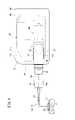
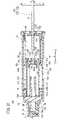
図1に示す本実施形態に係る薬液投与装置10は、薬液Mを生体内に投与するために使用される。薬液投与装置10は、薬液容器12内に充填された薬液Mをプランジャ組立体14Aの押圧作用下に比較的長い時間(例えば、数分~数時間程度)をかけて持続的に生体内に投与する。薬液投与装置10は、薬液Mを間欠的に生体内に投与してもよい。薬液Mとしては、例えば、タンパク質製剤、麻薬性鎮痛薬、利尿薬等が挙げられる。 The drug
図1に示すように、薬液投与装置10の使用時において、薬液投与装置10には投与器具16として例えばパッチ式の針付きチューブ17が接続され、薬液容器12から吐出された薬液Mが針付きチューブ17を介して患者の体内に注入される。針付きチューブ17は、薬液容器12の先端部12cに接続可能なコネクタ18と、一端部がコネクタ18に接続された可撓性を有する送液チューブ19と、送液チューブ19の他端に接続され皮膚Sに貼着可能なパッチ部20と、パッチ部20から突出した穿刺針21とを備える。穿刺針21は皮膚Sに対して略垂直に穿刺される。なお、穿刺針21は皮膚Sに対して斜めに穿刺されるものであってもよい。 As shown in FIG. 1, when the drug
なお、薬液投与装置10に接続される投与器具16は上述したパッチ式の針付きチューブ17に限られず、例えば、送液チューブ19の先端に穿刺針(翼状針等)が接続されたものであってもよい。あるいは、投与器具16は、送液チューブ19を介さずに薬液容器12の先端部12cに接続可能な屈曲した針であってもよい。この場合、屈曲した針は、例えば薬液容器12の先端部12cから下方に略90°屈曲しており、薬液投与装置10の皮膚Sへの固定(貼り付け)に伴い皮膚Sに対して垂直に穿刺される。また、薬液容器12の先端部12cと投与器具16及び針の一部は薬液容器12の内部にあり、針の先端が薬液容器12より突出している形であってもよい。この場合でも、薬液投与装置10の皮膚Sへの固定(貼り付け)に伴い、針が皮膚Sに対して垂直に穿刺される。 The
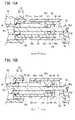
図1又は図2に示すように、薬液投与装置10は、薬液Mが充填された薬液容器12と、薬液容器12内に摺動可能に配置されたガスケット22と、軸方向(矢印X方向)に伸長可能であるとともにガスケット22を先端方向(矢印X1方向)に押圧可能なプランジャ組立体14Aと、プランジャ組立体14Aを駆動する駆動機構24と、薬液投与装置10の動作に必要な電力を供給する電池26と、駆動機構24を制御する制御部28と、薬液容器12、プランジャ組立体14A及び駆動機構24を支持するシャーシ構造30と、これらを収容する筐体31とを備える。 As shown in FIG. 1 or 2, the chemical
図2及び図3に示すように、薬液容器12は、内部に薬液室13を有する中空円筒状に形成されている。具体的に、薬液容器12は、その軸方向に内径及び外径が一定の胴部12aと、胴部12aの先端から縮径する肩部12bと、肩部12bから先端方向に突出した先端部12cとを有する。胴部12aの基端には基端開口12dが形成されている。薬液室13と連通する吐出口12eが先端部12cに形成されている。薬液Mは薬液容器12内に予め充填されている。薬液容器12は透明性を有する材料により構成されているとよい。 As shown in FIGS. 2 and 3, the
図3において、吐出口12eは、ゴム材やエラストマー材等の弾性樹脂材料からなる封止部材29によって液密に封止されている。封止部材29は、図1に示したコネクタ18が先端部12cに接続される際に、コネクタ18に設けられた針18aにより穿刺される。封止部材29は、先端に開口部を有する固定キャップ32によって薬液容器12の先端部12cに固定されている。封止部材29の先端面は、固定キャップ32の開口部から露出している。 In FIG. 3, the
ガスケット22は、薬液室13の基端側を液密に閉じている。薬液投与装置10の初期状態で、ガスケット22は薬液容器12の基端よりも先端側に位置する。ガスケット22は、ガスケット本体34と、ガスケット本体34の基端に装着された当接部材35とを備える。ガスケット本体34は、弾性を有する第1材料からなる。第1材料は、ゴム材やエラストマー材等の弾性樹脂材料である。 The
ガスケット本体34は、その外周部が薬液容器12(胴部12a)の内周面と液密に密着している。ガスケット本体34は、外周面が薬液容器12の胴部12aと液密に密着する基部34aと、基部34aから先端方向に突出するとともに先端方向に向かってテーパ状に縮径した錐部34bとを有する。 The outer peripheral portion of the gasket
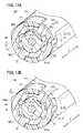
当接部材35は、第1材料よりも硬質な第2材料からなる。当接部材35は、プランジャ組立体14Aの後述するガスケット押圧部71に押圧される被押圧部35aを有する。また、当接部材35は、ガスケット本体34内に挿入される挿入部35bと、挿入部35bの基端に設けられた基端フランジ部35cとを有する。 The abutting
挿入部35bの外周部に設けられた雄ねじ35dが、ガスケット本体34の内周部に設けられた雌ねじ34cと螺合している。基端フランジ部35cは、基端面に被押圧部35aを有する。被押圧部35aは、基端フランジ部35cの基端面に間欠的に設けられるとともに、それぞれ当該基端面から基端方向(矢印X2方向)に突出した複数の凸部35a1である。凸部35a1は、基端に向かって膨出するドーム形状を有する。 The
プランジャ組立体14Aは、駆動機構24の駆動作用下に軸方向に伸長可能であり、伸長に伴ってガスケット22を薬液容器12内で前進させ、薬液容器12から薬液Mを押し出すように構成されている。薬液投与装置10の初期状態で、プランジャ組立体14Aの先端側は薬液容器12の基端側に挿入されている。なお、プランジャ組立体14Aの詳細については後述する。 The
図2において、駆動機構24は、電池26を電源として制御部28の制御作用下に駆動制御されるモータ36と、モータ36の出力軸に固定された駆動歯車37とを有する。 In FIG. 2, the
図1に示すように、筐体31内にシャーシ構造30が配置されている。図2に示すように、薬液容器12、駆動機構24及びプランジャ組立体14Aは、それぞれシャーシ構造30の所定位置に固定されている。シャーシ構造30は、シャーシ本体部材38と、シャーシ本体部材38に固定されるとともにプランジャ組立体14Aの送りねじ48を回転可能に支持する支持部材39と、シャーシ本体部材38に固定されるとともにシャーシ本体部材38との間でモータ36を保持するモータ保持部材40とを備える。 As shown in FIG. 1, the
シャーシ本体部材38は、底壁部を構成するベースプレート部38a(図10Aも参照)と、ベースプレート部38aの上面からベースプレート部38aの厚さ方向(上方)に突出するとともに薬液容器12のフランジ部12fが装着されたフランジ装着部38bとを有する。シャーシ本体部材38に、制御部28及び電池26が取り付けられた電気基板27が固定されている。 The
図1において、筐体31は、上述した薬液容器12、ガスケット22、プランジャ組立体14A、駆動機構24、電池26、制御部28及びシャーシ構造30を収容するように構成された中空状部材である。薬液容器12の先端部12cが筐体31から突出し、外部に露出している。筐体31は上面31aと底面31bを有する。筐体31の上面31aには、透明性を有する材料からなる窓部31wが設けられており、窓部31wを通して薬液容器12内の残液量を確認することができる。 In FIG. 1, the
薬液投与装置10は、例えば、患者の皮膚Sに貼り付けて使用するパッチタイプとして構成され得る。このようなパッチタイプの場合、筐体31の底面31bには、皮膚Sに貼着可能なシート状の貼着部(粘着部)が設けられる。薬液投与装置10の初期状態で貼着部の貼着面には剥離可能な保護シートが貼り付けられる。 The drug
なお、薬液投与装置10は、筐体31の底面31bにフックやクリップ等の装着具が設けられ、患者の衣服(例えば、ズボンのウエスト部分等)に引っ掛ける等して取り付けるタイプとして構成されてもよい。 The drug
図4に示すように、筐体31は、薬液容器12が挿入される第1開口部31cを有する。薬液容器12の先端部は、第1開口部31cを介して筐体31から突出している。薬液容器12の先端部近傍と筐体31との間に、リング状の防水パッキン42が配置されている。防水パッキン42は、X状の断面形状を有し、第1開口部31cに配置されている。防水パッキン42の外周部が全周に亘って第1開口部31cの内面に液密に密着し、防水パッキン42の内周部が全周に亘って薬液容器12(胴部12a)の外周面に液密に密着している。なお、防水パッキン42は、O状の断面形状を有していてもよい。 As shown in FIG. 4, the
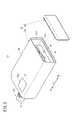
図5に示すように、筐体31は、薬液容器12を収容した収容部45及び収容部45に設けられた第2開口部31dを有する筐体本体部44と、第2開口部31dを封止する蓋体46と、第2開口部31dの縁部に取り付けられるとともに蓋体46と密着した環状の防水部材47とを備える。筐体本体部44に、上述した第1開口部31c(図4)が設けられている。第2開口部31dは、筐体本体部44の第1開口部31cが設けられた側と反対側の端部に設けられている。第2開口部31dは、シャーシ構造30よりも大きく形成されている。 As shown in FIG. 5, the
蓋体46は、長方形状に形成されており、薬液容器12の先端部が突出する側とは反対側の筐体31の壁部を構成している。防水部材47は、例えば、防水テープであり、第2開口部31dに設けられた枠形状の段部31eに取り付けられている。防水部材47は、長方形状の第2開口部31dに沿って長方形状に延在して環状をなしている。蓋体46が筐体本体部44の第2開口部31dに装着されることにより、防水部材47が蓋体46に液密に密着する。 The
次に、プランジャ組立体14Aの構成について詳細に説明する。 Next, the configuration of the
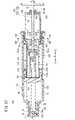
図3に示すように、プランジャ組立体14Aは、駆動機構24によって駆動される送りねじ48と、送りねじ48によって駆動される第1プランジャ50と、送りねじ48によって駆動される第2プランジャ52と、第2プランジャ52に保持されたナット部材54と、第2プランジャ52を支持するベース部56とを備える。 As shown in FIG. 3, the
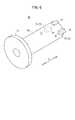
送りねじ48は、ロッド部58と、ロッド部58に連結されるとともに駆動歯車37によって駆動される従動歯車60とを有する。ロッド部58は、外周に雄ねじ62aが形成された雄ねじ部62と、雄ねじ部62の基端から基端方向に延出するとともに外周に雄ねじが形成されていない延出部63とを有する。 The
雄ねじ部62は、延出部63よりも長い。雄ねじ部62の先端部は、薬液容器12の内側に位置している。雄ねじ部62の外径は、延出部63の外径よりも大きい。ロッド部58はさらに、延出部63の基端に設けられた連結フランジ部64を有する。連結フランジ部64は、その基端面に断面非円形形状の連結用凹部65aを有し、従動歯車60の先端側軸部60cと相対回転不可能に連結(係合)している。 The
従動歯車60は、ロッド部58と同軸上に回転可能に配置されるとともに、駆動機構24の駆動歯車37と噛み合っている(図2参照)。従動歯車60は、外周部に歯部60aが形成された歯車部60bと、歯車部60bの先端面中央から先端方向に突出した先端側軸部60cと、歯車部60bの基端面中央から基端方向に突出した基端側軸部60dとを有する。先端側軸部60c及び基端側軸部60dが、シャーシ構造30の支持部材39によって回転可能に支持されている。 The driven
先端側軸部60cの先端には、ロッド部58の連結フランジ部64に設けられた連結用凹部65aに挿入された断面非円形形状の連結用凸部65bが設けられている。支持部材39の支持片39aと歯車部60bとの間には、従動歯車60を先端方向に弾性的に付勢するバネ66が配置されている。 At the tip of the tip
図6に示すように、第1プランジャ50は、中空状の第1筒状胴部68と、第1筒状胴部68の先端から径方向外方に突出した環状の第1先端フランジ70と、第1筒状胴部68の基端外周面から径方向外方に突出した第1突起部72と、第1突起部72と異なる周方向位置で第1筒状胴部68の基端外周面から径方向外方に突出した支持突起74とを有する。 As shown in FIG. 6, the
図3に示すように、第1筒状胴部68の基端内周面には、少なくともプランジャ組立体14Aが伸長動作を開始する前の初期状態で第1プランジャ50の雄ねじ部62と螺合した第1雌ねじ部68aが形成されている。 As shown in FIG. 3, the inner peripheral surface of the base end of the first
第1先端フランジ70は、薬液容器12の内周面に当接可能なフランジ部である。第1先端フランジ70の先端面は、ガスケット22を押圧可能なガスケット押圧部71である。薬液投与装置10の初期状態で、ガスケット押圧部71は、ガスケット22から若干の距離だけ離間している。 The
図6において、第1突起部72は、第2プランジャ52の後述する第1ガイド部86(図7A)によってガイドされる第1被ガイド部73を構成する。第1突起部72の先端面は、第2プランジャ52の後述する第2係合部98(図7A)に係合可能な第1係合部75を構成する。第1突起部72の基端面は、第2プランジャ52の後述する第2当接部53(図7B)に当接可能な第1当接部76を構成する。 In FIG. 6, the
薬液投与装置10の初期状態で、支持突起74は、第2プランジャ52の後述する仮係止爪部85a(図7A)を内側から支持する。 In the initial state of the drug
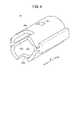
図7Aに示すように、第2プランジャ52は、プランジャ本体部78と、プランジャ本体部78に固定されたキャップ部材80とを備える。プランジャ本体部78は、中空状の第2筒状胴部82と、第2筒状胴部82の先端から径方向外方に突出した一対の第2先端フランジ83と、第2筒状胴部82の外面から径方向外方に突出するとともに軸方向に延在する第2突起部84とを有する。 As shown in FIG. 7A, the
第2筒状胴部82には、径方向に弾性変形可能な仮係止弾性片85が設けられている。仮係止弾性片85の端部(自由端部)には、外方に突出した仮係止爪部85aが設けられている。第2筒状胴部82には第1ガイド部86が設けられている。第1ガイド部86は、第1プランジャ50の第1被ガイド部73と係合し、第2プランジャ52に対する第1プランジャ50の回転を防止して第1プランジャ50の軸方向運動をガイドする。第2先端フランジ83は、弧状に延在している。一対の第2先端フランジ83間には、切欠き状の隙間が形成されている。 The second
図7Bに示すように、第1ガイド部86は、軸方向に沿って延在して第1プランジャ50の第1被ガイド部73(図6)を軸方向にガイドする軸方向ガイド86aと、軸方向ガイド86aの先端に連続するとともに周方向に延在して第1被ガイド部73を周方向にガイドする回転ガイド86bとを有する。回転ガイド86bは、軸方向ガイド86aに連続する第1端部86b1と、第1端部86b1とは異なる第2端部86b2とを有する。 As shown in FIG. 7B, the
第1ガイド部86はさらに、回転ガイド86bの第2端部86b2に連続するロック部86cを有する。ロック部86cは、軸方向ガイド86aよりも短い長さで第2端部86b2から基端方向に延出するとともに第1プランジャ50の第1被ガイド部73を係止可能である。 The
本実施形態では、図8Aに示すように、軸方向ガイド86aは、第2筒状胴部82の周壁部を壁厚方向に貫通する孔部であり、第2筒状胴部82の軸を基準に互いに反対側の位置に2つ設けられている。回転ガイド86bは、第2筒状胴部82の軸を基準に互いに反対側の位置に2つ設けられている。ロック部86cは、第2筒状胴部82の周壁部を壁厚方向に貫通する孔部であり、第2筒状胴部82の軸を基準に互いに反対側の位置に2つ設けられている。ロック部86cの基端面は、第1プランジャ50の第1当接部76(図6)に当接可能な第2当接部53を構成する。 In the present embodiment, as shown in FIG. 8A, the
図8Bに示すように、第2筒状胴部82の基端部には、ナット収容部88が設けられている。ナット収容部88は、ナット部材54を回転不可能且つ軸方向に移動可能に収容する。ナット収容部88の内周形状は、ナット部材54の外径に合わせて六角形状に形成されている。ナット収容部88の内周面88aには、軸方向に沿って延在し且つ周方向に間隔を置いて配置された複数のリブ88bが形成されており、複数のリブ88bがナット部材54の外周面に当接する。 As shown in FIG. 8B, a
図3に示すように、ナット収容部88は、先端台座部89と基端台座部90とを有する。先端台座部89は、第2筒状胴部82の内側に設けられた孔部を有する内周突出壁82a(図7Bも参照)の基端面である。基端台座部90は、第2筒状胴部82の基端内側に固定された台座部材82bの先端面である。 As shown in FIG. 3, the
ナット部材54を先端方向へ付勢するナット付勢部材92が、ナット収容部88内に配置されている。本実施形態において、ナット付勢部材92は、コイルバネである。ナット付勢部材92に、送りねじ48のロッド部58が挿入されている。 A
プランジャ組立体14Aの初期状態で、ナット部材54の先端面が先端台座部89に当接し、ナット付勢部材92の先端がナット部材54の基端面に当接し、ナット付勢部材92の基端が基端台座部90に当接する。 In the initial state of the
図8Aにおいて、第2突起部84は、ベース部56の後述する第2ガイド部100(図9)によってガイドされる第2被ガイド部94を構成する。第2突起部84は、第2筒状胴部82の略全長に亘って軸方向に延在するとともに、第1ガイド部86の軸方向ガイド86aとロック部86cとの間に設けられている。第2突起部84の先端は、第2先端フランジ83に連続している。本実施形態では、図8Bに示すように、第2突起部84は、第2筒状胴部82の軸を基準に互いに反対側の位置に2つ設けられている。 In FIG. 8A, the
図3に示すように、キャップ部材80は、プランジャ本体部78の先端に固定されている。図7Aにおいて、キャップ部材80は、開口96aを有する先端リング部96と、先端リング部96の基端面外縁から基端方向に突出した一対の連結用アーム97とを有する。先端リング部96の開口96aに第1プランジャ50の第1筒状胴部68(図6)が挿入されている。先端リング部96の外周部は、薬液容器12の内周面に当接可能な先端外周部である。先端リング部96の基端面は、第1プランジャ50の第1係合部75に係合可能な第2係合部98を有する。 As shown in FIG. 3, the
連結用アーム97の自由端部には、内方に向かって突出した係合用爪97aが設けられている。係合用爪97aが、仮係止弾性片85の両側に形成されたスリット85bの先端に係合することにより、キャップ部材80がプランジャ本体部78から離脱することが防止されている。 The free end of the connecting
図3に示すように、ナット部材54は、送りねじ48の雄ねじ部62に螺合可能な第2雌ねじ部54aが内周に形成されるとともに、送りねじ48が挿入されている。ナット部材54には、初期状態で送りねじ48の延出部63が挿入されている。ナット部材54は、六角形状の外形を有する。なお、ナット部材54は、他の多角形状等の非円形形状の外形を有していてもよい。 As shown in FIG. 3, in the
図2に示すように、ベース部56はシャーシ構造30に固定されている。図9に示すように、ベース部56は、中空状部材であり、軸方向に延在する溝状の第2ガイド部100を有する。本実施形態において、第2ガイド部100は、ベース部56の軸を基準に互いに反対側の位置に2つ設けられている。第2ガイド部100は、第2プランジャ52の第2被ガイド部94(図7A等)と係合し、送りねじ48に対する第2プランジャ52の回転を防止して第2プランジャ52の軸方向移動をガイドする。 As shown in FIG. 2, the
ベース部56は、第2プランジャ52の仮係止爪部85a(図7A等)が離脱可能に挿入された仮係止凹部102を有する。本実施形態において、仮係止凹部102は、ベース部56の周壁部を厚さ方向に貫通する孔の形態を有する。なお、仮係止凹部102は、ベース部56の内周面に設けられた溝であってもよい。ベース部56の先端には、キャップ部材80の連結用アーム97(図7A)が挿入される切欠き56aが設けられている。 The
上記のように構成された薬液投与装置10は、例えば、以下の手順で組み立てられる。 The drug
図10Aのように、プランジャ組立体14Aと、駆動機構24と、制御部28及び電池26が取り付けられた電気基板27とを、シャーシ構造30の所定位置に組み付ける(固定する)。 As shown in FIG. 10A, the
次に、図10Bのように、プレフィルドシリンジ104をシャーシ構造30に組み付ける。プレフィルドシリンジ104は、薬液容器12の先端部に封止部材29及び固定キャップ32が装着され、薬液容器12内に薬液Mが充填され、且つ薬液容器12内にガスケット22が挿入された組立体である。 Next, as shown in FIG. 10B, the
次に、図10Cのように、筐体本体部44の第2開口部31dを介して、プランジャ組立体14A等が組み付けられたシャーシ構造30を筐体本体部44内に挿入する。その際、筐体本体部44の第1開口部31cに配置された防水パッキン42(図4)に薬液容器12が挿入され、薬液容器12の外周面に防水パッキン42が液密に密着する。次に、筐体本体部44の第2開口部31dを蓋体46で閉じる。その際、筐体本体部44の第2開口部31dに配置された防水部材47に蓋体46が液密に密着する。これにより、防水構造が構築される。 Next, as shown in FIG. 10C, the
次に、上記のように構成された薬液投与装置10の作用を説明する。 Next, the operation of the drug
図3に示す初期状態から駆動機構24(図2)によって送りねじ48が回転すると、図11に示すように、送りねじ48の雄ねじ部62と螺合する第1プランジャ50が前進する。この際、第1被ガイド部73(図6)が第1ガイド部86(図7A)にガイドされているため、第1プランジャ50は、回転が規制された状態で前進する。一方、第2プランジャ52の仮係止爪部85aはベース部56の仮係止凹部102に挿入されており、且つ送りねじ48の雄ねじ部62はナット部材54に螺合していない(送りねじ48の延出部63がナット部材54に挿入されている)ため、送りねじ48が回転しても第2プランジャ52は前進しない。 When the
図12に示すように、送りねじ48の回転に伴い第1プランジャ50が第2プランジャ52の先端近傍まで前進すると、第1プランジャ50が送りねじ48の回転に合わせて所定角度回転する。具体的には、図13Aのように、第1プランジャ50の第1被ガイド部73が、第2プランジャ52の第1ガイド部86の先端に設けられた回転ガイド86bに到達する(軸方向ガイド86aから離脱する)と、第1プランジャ50は第2プランジャ52に対して回転可能となる。このため、第1被ガイド部73が回転ガイド86bに到達した第1プランジャ50は、第1被ガイド部73が回転ガイド86bの第1端部86b1から第2端部86b2に移動する間だけ、送りねじ48に連れ回る。 As shown in FIG. 12, when the
そして、図13Bのように、第1被ガイド部73が回転ガイド86bの第2端部86b2に当接すると、第1プランジャ50の第2プランジャ52に対する相対回転が再び規制される。これにより、送りねじ48の回転に伴い、第1プランジャ50が再び前進を開始し、第1プランジャ50の第1係合部75(第1突起部72の先端面)が、第2プランジャ52の第2係合部98(キャップ部材80の先端リングの基端面)(図7A)に係合する。 Then, as shown in FIG. 13B, when the first guided
そして、第1プランジャ50の第1係合部75と第2プランジャ52の第2係合部98とが係合した状態で第1プランジャ50が前進すると、図14に示すように、第1プランジャ50が第2プランジャ52を前進させる。すなわち、送りねじ48の回転に伴い、第1プランジャ50が第2プランジャ52を引き連れて前進する。この際、第2プランジャ52の仮係止爪部85aは、ベース部56の仮係止凹部102から外れる。第2プランジャ52の前進に伴い、送りねじ48の雄ねじ部62が、第2プランジャ52に配置されたナット部材54に螺合する。 Then, when the
具体的には、第2プランジャ52が前進を開始すると、図15Aのように、雄ねじ部62の基端がナット部材54の第2雌ねじ部54aの先端に接触する。この接触と同時に第2雌ねじ部54aが雄ねじ部62に噛み合わない場合でも、ナット部材54がナット収容部88内で軸方向に相対的にスライド可能であるため、図15Bのように第2プランジャ52は第1プランジャ50につられて前進することができる。その際、ナット部材54は、ナット付勢部材92の付勢力に抗して、前進する第2プランジャ52に対して相対的に基端方向へ移動する。 Specifically, when the
そして、ナット部材54がナット付勢部材92により先端方向に付勢されつつ第2プランジャ52が前進する間に、雄ねじ部62と第2雌ねじ部54aとの位相が合ったときに、送りねじ48とナット部材54とが螺合する。雄ねじ部62と第2雌ねじ部54aとの噛み合いが開始することにより、送りねじ48の雄ねじ部62が第1雌ねじ部68a及び第2雌ねじ部54aの両方に螺合したダブルねじ状態が開始する。 Then, when the
そして、図16に示すように、送りねじ48の回転に伴い、ダブルねじ状態で第1プランジャ50と第2プランジャ52が前進する。その際、ナット部材54の先端面が先端台座部89から離間しているため(図15B)、ナット部材54が第2プランジャ52を前進させるのではなく、第1係合部75と第2係合部98との係合により、第1プランジャ50が第2プランジャ52を前進させる。なお、ナット収容部88により回転規制状態とされたナット部材54は、送りねじ48の回転に伴い、先端台座部89との距離を維持したまま前進する(第2プランジャ52と同じ速度で前進する)。 Then, as shown in FIG. 16, as the
送りねじ48の回転に伴い第1プランジャ50及び第2プランジャ52がさらに前進すると、図17に示すように、第1プランジャ50の第1雌ねじ部68aが送りねじ48の雄ねじ部62から外れる(第1雌ねじ部68aの螺合が解除される)。第1プランジャ50と送りねじ48との螺合が解除されると、送りねじ48と螺合するナット部材54が第2プランジャ52を前進させ、前進する第2プランジャ52が、第1プランジャ50を前進させる。 When the
具体的には、第1プランジャ50と送りねじ48との螺合が解除されると、送りねじ48の回転に伴いナット部材54が前進して第2プランジャ52の先端台座部89に当接する。従って、前進するナット部材54が先端台座部89を先端方向に押圧することにより、第2プランジャ52が前進を開始する。その際、送りねじ48との螺合が解除された第1プランジャ50は停止しているため、第2プランジャ52の前進に伴い、図18に示すように、第2プランジャ52の第2当接部53が、第1プランジャ50の第1当接部76に当接する。従って、前進する第2プランジャ52の第2当接部53が、第1当接部76を先端方向に押圧することにより、第1プランジャ50が再び前進し始める。これにより、ナット部材54のみが送りねじ48に螺合した状態で、第1プランジャ50及び第2プランジャ52が前進して、送液が行われる。 Specifically, when the screw between the
そして、図19に示すように、ガスケット22が薬液容器12の肩部12bに当接する位置まで第1プランジャ50及び第2プランジャ52が前進すると、送りねじ48の回転が停止して、送液が完了する。 Then, as shown in FIG. 19, when the
この場合、本実施形態に係るプランジャ組立体14Aを備えた薬液投与装置10は、以下の効果を奏する。 In this case, the drug
プランジャ組立体14Aは、雄ねじ部62及び延出部63を有する送りねじ48と、第1雌ねじ部68aを有する第1プランジャ50と、第2雌ねじ部54aを有する第2プランジャ52と、第2プランジャ52に対して想定的に軸方向に移動可能なナット部材54と、ベース部56とを備える。そして、送りねじ48の回転に伴い、まず第1プランジャ50が前進し、その後、第1プランジャ50が第2プランジャ52を引き連れて前進し、その後、ナット部材54が送りねじ48と螺合し、その後、第2プランジャ52が第1プランジャ50を前進させる。 The
このように構成されたプランジャ組立体14Aは、複数段階に亘って伸長するため、全長を短くでき、その分、プランジャ組立体14Aが搭載される薬液投与装置10の小型化を図ることができる。装置の小型化により、患者の体表面に貼付する場合における貼付に必要な面積を小さくできるため、患者の体表面に貼付する等の用途にも容易に適用することができる。また、装置の小型化により、持ち運び、保管等、ユーザビリティの向上を図ることができる。 Since the
また、ナット部材54が第2プランジャ52に対して軸方向に相対移動可能であるため、送りねじ48の雄ねじ部62とナット部材54との接触と同時に送りねじ48の雄ねじ部62とナット部材54の第2雌ねじ部54aとが噛み合わない場合でも、その後に雄ねじ部62と第2雌ねじ部54aとの位相が合致したときには螺合することが可能である。従って、送りねじ48によりナット部材54を介して第2プランジャ52を確実に前進させることができる。 Further, since the
プランジャ組立体14Aは、ナット部材54を先端方向へ付勢するナット付勢部材92を備え、初期状態で、ナット部材54の先端面が先端台座部89に当接し、ナット付勢部材92の先端がナット部材54の基端面に当接し、ナット付勢部材92の基端が基端台座部90に当接する。この構成により、ナット部材54が常に先端方向に付勢されているため、送りねじ48の雄ねじ部62とナット部材54の第2雌ねじ部54aとの位相が合ったときに、送りねじ48とナット部材54とを確実に螺合させることができる。すなわち、雄ねじ部62のピッチ分だけ第2プランジャ52が前進する間に、送りねじ48とナット部材54とは必ず螺合する。 The
なお、ナット付勢部材92は設けられなくてもよい。この場合、第2プランジャ52が前進する間に雄ねじ部62と第2雌ねじ部54aとの噛み合わせに何回か失敗しても、ナット部材54の可動範囲内のどこかで噛み合う。従って、送りねじ48の回転により第2プランジャ52を前進させることができる。 The
ナット収容部88の内周面には、軸方向に沿って延在し且つ周方向に間隔を置いて配置された複数のリブ88bが形成されており、複数のリブ88bがナット部材54の外周面に当接する。この構成により、第2プランジャ52に対するナット部材54の摺動抵抗を低減し、第2プランジャ52に対するナット部材54の相対軸方向移動を円滑にすることができる。 A plurality of
第1プランジャ50の先端は、薬液容器12の内周面に当接可能なフランジ部を有する。この構成により、第1プランジャ50の座屈を防止することができる。 The tip of the
第2プランジャ52は、ナット収容部88と第1ガイド部86と第2被ガイド部94と第2当接部53を有するプランジャ本体部78と、プランジャ本体部78に固定され、第2係合部98を有するキャップ部材80とを備える。この構成により、射出成形により、第1ガイド部86、第2被ガイド部94、第2当接部53及び第2係合部98を有する第2プランジャ52を容易に作製することができる。 The
キャップ部材80は、薬液容器12の内周面に当接可能な先端外周部を有する。この構成により、第2プランジャ52の座屈を防止することができる。 The
第2プランジャ52の第1ガイド部86は、第1プランジャ50の第1被ガイド部73を軸方向にガイドする軸方向ガイド86aと、軸方向ガイド86aの先端に連続して第1被ガイド部73を周方向にガイドする回転ガイド86bとを有する(図7B)。この構成により、第1ガイド部86の先端で、送りねじ48の回転に伴い第1プランジャ50を回転させることができる。 The first guided
第2プランジャ52の第1ガイド部86は、回転ガイド86bの第2端部86b2に連続するロック部86cを有する(図7B)。この構成により、第1被ガイド部73が第1ガイド部86の軸方向ガイド86aに戻ることが防止される。 The
第2プランジャ52は、仮係止爪部85aが端部に設けられた仮係止弾性片85を有し、ベース部56は、仮係止爪部85aが離脱可能に挿入された仮係止凹部102を有する。この構成により、ベース部56に対して第2プランジャ52が仮止めされるため、送りねじ48がナット部材54に螺合する前に第2プランジャ52が第1プランジャ50の前進につられて前進することを防止することができる。 The
第1プランジャ50は、仮係止爪部85aを内側から支持する支持突起74を有する。この構成により、第1プランジャ50がある程度前進するまで仮係止爪部85aが仮係止凹部102から離脱することを防止することができる。 The
筐体31は、薬液容器12が挿入される第1開口部31cを有する(図4)。そして、薬液容器12は、第1開口部31cを介して筐体31から突出した先端部を有し、薬液容器12の先端部近傍と筐体31との間に、リング状の防水パッキン42が配置されている。この構成により、第1開口部31cを介した筐体31内への水の浸入を防止することができる。 The
筐体31は、収容部45及び第2開口部31dを有する筐体本体部44と、第2開口部31dを封止する蓋体46と、第2開口部31dに取り付けられた環状の防水部材47とを備える(図5)。この構成により、第2開口部31dを介した筐体31内への水の浸入を防止することができる。 The
薬液投与装置10は、薬液容器12、駆動機構24及びプランジャ組立体14Aがそれぞれ所定位置に固定されたシャーシ構造30を備える。そして、筐体31内にシャーシ構造30が配置され、第2開口部31dは、シャーシ構造30よりも大きく形成されている。この構成により、第2開口部31dを介して、筐体31からプランジャ組立体14A等をシャーシ構造30ごと簡単に取り出すことができる。 The chemical
第1プランジャ50は、第2プランジャ52の第1ガイド部86の先端で、送りねじ48の回転に伴い第2プランジャ52に対して所定角度だけ回転可能である(図13A及び図13B)。そして、ガスケット22は、弾性を有する第1材料からなるガスケット本体34と、第1材料よりも硬質な第2材料からなり、ガスケット本体34の基端に装着された当接部材35とを備える(図3)。当接部材35は、ガスケット押圧部71に押圧される被押圧部35aを有する。ガスケット押圧部71は、第1材料よりも硬質な材料からなる。この構成により、ガスケット22に対する第1プランジャ50の回転方向の摺動抵抗を小さくできる。このため、ガスケット22が第1プランジャ50の回転を阻害することがない。 The
当接部材35は、ガスケット本体34内に挿入される挿入部35bと、挿入部35bの基端に設けられた基端フランジ部35cとを有する。基端フランジ部35cは、基端面に被押圧部35aを有する。被押圧部35aは、基端面に間欠的に設けられるとともに、それぞれ基端面から基端方向に突出した複数の凸部である。この構成により、ガスケット22に対する第1プランジャ50の回転方向の摺動抵抗を効果的に小さくすることができる。 The
凸部は、基端に向かって膨出するドーム形状である。この構成により、ガスケット22に対する第1プランジャ50の回転方向の摺動抵抗を一層効果的に小さくすることができる。 The convex portion has a dome shape that bulges toward the base end. With this configuration, the sliding resistance of the
プランジャ組立体14Aの駆動方法では、送りねじ48の回転に伴い第1プランジャ50が軸方向に沿って前進し(図11)、第1プランジャ50の第1係合部75が第2プランジャ52の第2係合部98に係合し、前進する第1プランジャ50が第2プランジャ52を前進させる(図14)。また、第2プランジャ52の前進に伴いナット部材54が第2プランジャ52に対して相対的に基端方向へ移動し(図15B)、ナット部材54の移動により当該ナット部材54が送りねじ48の雄ねじ部62と螺合する(図16)。そして、雄ねじ部62と螺合したナット部材54が、送りねじ48の回転に伴い前進して第2プランジャ52を前進させ、前進する第2プランジャ52が第1プランジャ50を前進させる(図16)。これにより、送りねじ48の雄ねじ部62とナット部材54の第2雌ねじ部54aとを円滑に螺合させることができる。このため、送りねじ48によりナット部材54を介して第2プランジャ52を確実に前進させることができる。 In the driving method of the
プランジャ組立体14Aの駆動方法では、ナット部材54がナット付勢部材92により先端方向に付勢されている。また、ナット部材54は、ナット付勢部材92の付勢力に抗して第2プランジャ52に対して相対的に基端方向へ移動した後に、ナット部材54の第2雌ねじ部54aが送りねじ48の雄ねじ部62に螺合する(図15B及び図16)。これにより、送りねじ48とナット部材54とを確実に螺合させることができる。 In the driving method of the
プランジャ組立体14Aの駆動方法では、送りねじ48に対する回転が規制された第1プランジャ50が第2プランジャ52の先端近傍まで移動し(図12)、第2プランジャ52の先端近傍まで移動した第1プランジャ50が送りねじ48の回転に合わせて所定角度回転する(図13A及び図13B)。また、所定角度回転した第1プランジャ50は回転が再び規制されるとともに、第1プランジャ50の第1係合部75が第2プランジャ52の第2係合部98に係合する。そして、第1係合部75が第2係合部98に係合した第1プランジャ50が、第2プランジャ52を引き連れて前進する(図14)。これにより、送りねじ48の回転に伴い前進する第1プランジャ50ンにより第2プランジャ52を前進させることができる。 In the driving method of the
プランジャ組立体14Aの駆動方法では、送りねじ48の雄ねじ部62が第1雌ねじ部68aと第2雌ねじ部54aの両方に螺合した状態(ダブルねじ状態)で、送りねじ48が回転して、第1プランジャ50と第2プランジャ52が前進する(図16)。また、第2プランジャ52が所定長前進した後に、第1プランジャ50の第1雌ねじ部68aが雄ねじ部62から離脱する(図17)。そして、第1雌ねじ部68aが雄ねじ部62から離脱し且つ第2雌ねじ部54aが雄ねじ部62と螺合した状態で、第2プランジャ52が第1プランジャ50を前進させる。これにより、送りねじ48の雄ねじ部62が第1雌ねじ部68aと第2雌ねじ部54aの両方に螺合したダブルねじ状態から、第2雌ねじ部54aと雄ねじ部62のみが螺合した状態への移行が円滑に行われ、第2プランジャ52により第1プランジャ50を前進させることができる。 In the driving method of the
上述した薬液投与装置10において、プランジャ組立体14Aに代えて、図20~図31に示すプランジャ組立体14Bが採用されてもよい。なお、プランジャ組立体14Bにおいて、プランジャ組立体14Aと同一又は同様の構成要素には、同一の符号を付し、詳細な説明を省略する。 In the above-mentioned chemical
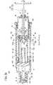
図21に示すように、プランジャ組立体14Bは、駆動機構24(図2)によって駆動される送りねじ108と、送りねじ108によって先端方向に駆動される第1プランジャ110と、送りねじ108によって先端方向に駆動される第2プランジャ112と、第2プランジャ112に保持されたナット部材54と、第2プランジャ112を支持するベース部114と、第1プランジャ110の内部に配置された支持機構116とを備える。 As shown in FIG. 21, the
送りねじ108は、ロッド部118と、ロッド部118に連結されるとともに駆動歯車37(図2)によって駆動される従動歯車120とを有する。ロッド部118は、雄ねじ62aが形成された雄ねじ部62と、雄ねじ部62の基端から基端方向に延出するとともに雄ねじが形成されていない延出部63とを有する。従動歯車120は、ロッド部118の延出部63の基端に相対回転不可能に固定されるとともに、駆動機構24の駆動歯車37(図2)と噛み合っている。 The
第1プランジャ110は、第2プランジャ112に支持された中空状の第1プランジャ本体122と、第1プランジャ本体122の先端に固定されたガスケット押圧部124と、第1プランジャ本体122の基端に固定されたナット部材126(以下、「第1ナット部材126」という)とを有する。 The
図22に示すように、第1プランジャ本体122の周壁部123は、軸方向に垂直な断面における輪郭形状が非円形の外形を有する。具体的に、第1プランジャ110の周壁部123は、互いに対向する一対の平坦壁部123aと、互いに対向する一対の円弧状壁部123bとを有する。第1プランジャ110の周壁部123の外面が、第2プランジャ112の後述する第1ガイド部142によってガイドされる第1被ガイド部127を構成する。 As shown in FIG. 22, the
図23に示すように、第1プランジャ本体122は、第1プランジャ本体122の内外方向に弾性変形可能な係合弾性片122aが設けられている。係合弾性片122aは、第1プランジャ本体122の軸を基準に互いに反対側に2つ設けられている。係合弾性片122aの基端(自由端部)に、外方に突出した係合爪部122bが設けられている。係合爪部122bの先端面は、第2プランジャ112の後述する第2係合部150に係合可能な第1係合部128を構成する。係合爪部122bの基端面は、第2プランジャ112の後述する第2当接部152に当接可能な第1当接部130を構成する。 As shown in FIG. 23, the first plunger
ガスケット押圧部124は、ガスケット131に挿入された挿入部124aと、挿入部124aの基端から径方向外方に突出した基端フランジ部124bと、挿入部124aの先端壁部の中央から基端方向に突出した中空状の中央筒部124cとを有する。基端フランジ部124bは、ガスケット131の基端面に対向するとともに、薬液容器12の内周面に当接可能である。中央筒部124cは、基端フランジ部124bよりも基端方向に突出している。図23に示すプランジャ組立体14Bの初期状態で、送りねじ108の雄ねじ部62は中央筒部124cに挿入されている。 The
第1ナット部材126は、第1プランジャ本体122の基端内部に設けられたナット保持部132により、第1プランジャ本体122に対して回転不可能に保持(固定)されている。第1ナット部材126の内周部に、第1雌ねじ部68aが形成されている。なお、第1ナット部材126を無くし、第1雌ねじ部68aが第1プランジャ本体122に直接形成されていてもよい。 The
図21に示すように、第2プランジャ112は、筒状胴部134と、筒状胴部134の先端から外方に突出した先端フランジ部136と、筒状胴部134の外面に設けられた仮係止爪部138と、筒状胴部134の基端内部に設けられたナット収容部140とを有する。仮係止爪部138は、第2プランジャ112の軸を基準に互いに反対側に2つ設けられている。仮係止爪部138は、先端方向に向かって内方に傾斜した傾斜面を有する。 As shown in FIG. 21, the
ナット収容部140にナット部材54(以下、「第2ナット部材54」という)が軸方向に相対移動可能に収容されている。なお、上述したプランジャ組立体14Aと同様に、ナット収容部140にナット付勢部材92及び台座部材82b(図3等)が配置されてもよい。 A nut member 54 (hereinafter referred to as "
図22に示すように、第2プランジャ112の筒状胴部134は、軸方向に垂直な断面における輪郭形状が非円形の外形を有する。具体的には、筒状胴部134は、互いに対向する一対の平坦壁部134aと、互いに対向する一対の円弧状壁部134bとを有する。筒状胴部134の内面が、第2プランジャ112に対する第1プランジャ110の回転を防止して第1プランジャ110の軸方向運動をガイドする第1ガイド部142を構成している。筒状胴部134の外面が、ベース部114の後述する第2ガイド部164によってガイドされる第2被ガイド部144を構成している。 As shown in FIG. 22, the
図23に示すように、第2プランジャ112の筒状胴部134の先端には先端凹部146が設けられ、筒状胴部134の基端には基端凹部148が設けられている。先端凹部146及び基端凹部148は、それぞれ筒状胴部134の周壁を厚さ方向に貫通している。先端凹部146の先端面は、第1プランジャ110の第1係合部128に係合可能な第2係合部150を構成している。 As shown in FIG. 23, a
第2係合部150は、基端方向に向かって内方に傾斜している。先端凹部146の基端面は、第1プランジャ110の第1当接部130に当接可能な第2当接部152を構成している。第2当接部152は、先端方向に向かって内方に傾斜している。基端凹部148の先端面は、先端方向に向かって内方に傾斜している。 The second
図21に示すように、ベース部114は、中空状部材であり、薬液容器12の基端開口12dに嵌合している。ベース部114は、ベース部胴体154と、ベース部胴体154の先端から外方に突出した嵌合突起156と、ベース部胴体154の基端から外方に突出した基端フランジ158と、ベース部胴体154の基端から内方に突出した仮係止突起160を有する。基端フランジ158の先端面は、薬液容器12の基端面に当接している。仮係止突起160には、第2プランジャ112の仮係止爪部138が解除可能に係合する。 As shown in FIG. 21, the
ベース部胴体154の内面には、仮係止突起160を通過した仮係止爪部138が挿入可能な溝部162が設けられている。仮係止爪部138は、軸方向に延在している。 A
図22に示すように、ベース部胴体154は、軸方向に垂直な断面において、第2プランジャ112の外形に沿った非円形形状を有する。ベース部胴体154の内面が第2ガイド部164を構成している。第2ガイド部164は、第2プランジャ112の内面である第2被ガイド部144と係合し、ベース部114に対する第2プランジャ112の回転を防止して第2プランジャ112の軸方向移動をガイドする。 As shown in FIG. 22, the
図23に示すように、支持機構116は、第1プランジャ本体122内に第1プランジャ本体122に対して相対的回転不可能且つ相対軸方向移動可能に配置された支持部材166と、支持部材166に保持された第3ナット部材168と、支持部材166を基端方向に弾性的に付勢する付勢部材170とを備える。支持部材166は、第1プランジャ本体122の内面に近接(又は接触)して設けられた一対の支持アーム167を有する。後述するように、支持アーム167は、係合弾性片122aを内側から支持可能である。 As shown in FIG. 23, the
第3ナット部材168は、支持部材166に対して回転不可能に保持されている。第3ナット部材168の内周部には、第3雌ねじ部168aが形成されている。プランジャ組立体14Bの初期状態で、第3雌ねじ部168aは、送りねじ108の雄ねじ部62に螺合している。 The
付勢部材170は、第1プランジャ110のガスケット押圧部124と支持部材166との間に配置されたコイルバネである。付勢部材170の先端は、ガスケット押圧部124の挿入部124aの先端壁部に当接している。付勢部材170の基端は、支持部材166に当接している。ガスケット押圧部124の中央筒部124cが、付勢部材170に挿入されている。 The urging
次に、薬液投与装置10においてプランジャ組立体14Bが採用された場合の作用を説明する。 Next, the operation when the
図23に示す初期状態から駆動機構24(図2)によって送りねじ108が回転すると、図24に示すように、送りねじ108の雄ねじ部62と螺合する第1プランジャ110が前進する。この際、第1被ガイド部127(第1プランジャ本体122の外面)が第1ガイド部142(第2プランジャ112の内面)にガイドされているため(図22)、第1プランジャ110は、回転が規制された状態で前進する。第3ナット部材168が雄ねじ部62に螺合しているため、送りねじ108の回転に伴い、第1プランジャ110と一緒に支持部材166も前進する。 When the
一方、第2プランジャ112の仮係止爪部138はベース部114の仮係止突起160に挿入されており(図21)、且つ送りねじ108の雄ねじ部62はナット部材54に螺合していない(送りねじ108の延出部63がナット部材54に挿入されている)ため、送りねじ108が回転しても第2プランジャ112は前進しない。また、図24に示すように、第1プランジャ110が前進する際、第1プランジャ110の係合爪部122bは、係合弾性片122aのヒンジ機能(弾性変形機能)により、第2プランジャ112の基端凹部148から離脱して、第2プランジャ112内部へと引き込まれる。 On the other hand, the temporary
図25に示すように、送りねじ108の回転に伴い第1プランジャ110及び支持部材166がさらに前進すると、支持部材166に保持された第3ナット部材168が送りねじ108の雄ねじ部62から離脱する。このため、これ以降は、送りねじ108の回転によって第3ナット部材168及び支持部材166が前進することはない。支持部材166は、付勢部材170により基端方向に付勢されているため、送りねじ108の先端に押し付けられる。 As shown in FIG. 25, when the
また、第1プランジャ110の前進に伴い、第1プランジャ110の係合弾性片122aがその弾性復元力によって外方に変位して、係合爪部122bが第2プランジャ112の先端凹部146に入り込み、第1プランジャ110の第1係合部128(係合爪部122bの先端面)が、第2プランジャ112の第2係合部150(先端凹部146の先端面)に係合する。 Further, as the
従って、図26に示すように、第1プランジャ110の第1係合部128と第2プランジャ112の第2係合部150とが係合した状態で第1プランジャ110が前進すると、第1プランジャ110が第2プランジャ112を前進させる。すなわち、送りねじ108の回転に伴い、第1プランジャ110が第2プランジャ112を引き連れて前進する。この際、第2プランジャ112の仮係止爪部138(図21)は、ベース部114の仮係止突起160(図21)を乗り越えて、ベース部114の内面に設けられた溝部162(図21)へと入り込む。 Therefore, as shown in FIG. 26, when the
第1プランジャ110の前進に伴い、付勢部材170により基端方向に付勢された支持部材166は、第1プランジャ110に対して基端方向に相対変位する(支持部材166の位置は、第3ナット部材168と雄ねじ部62との螺合が解除されたときから変わらない)。第2プランジャ112の前進に伴い、雄ねじ部62の基端がナット部材54の第2雌ねじ部54aの先端に接触する。 As the
図27に示すように、第2プランジャ112の前進に伴い、送りねじ108の雄ねじ部62が、第2プランジャ112に配置された第2ナット部材54に螺合する。具体的には、第2ナット部材54が雄ねじ部62との螺合に何回か(例えば、1、2回)失敗しても、第2プランジャ112の前進に伴い、第2ナット部材54が第2プランジャ112に対して軸方向に相対移動することで、第2ナット部材54と雄ねじ部62との螺合が達成される。雄ねじ部62と第2雌ねじ部54aとの噛み合いが開始することにより、送りねじ108の雄ねじ部62が第1雌ねじ部68a及び第2雌ねじ部54aの両方に螺合したダブルねじ状態が開始する。 As shown in FIG. 27, as the
そして、送りねじ108の回転に伴い、ダブルねじ状態で第1プランジャ110と第2プランジャ112が前進する。その際、ナット部材54の先端面が先端台座部89から離間している場合、ナット部材54が第2プランジャ112を前進させるのではなく、第1係合部128と第2係合部150との係合により、第1プランジャ110が第2プランジャ112を前進させる。 Then, as the
送りねじ108の回転に伴い第1プランジャ110及び第2プランジャ112がさらに前進すると、図28に示すように、第1プランジャ110の第1ナット部材126(第1雌ねじ部68a)が送りねじ108の雄ねじ部62から外れる(第1雌ねじ部68aの螺合が解除される)。第1プランジャ110の前進に伴い、第1プランジャ110のナット収容部140が支持部材166に当接する位置まで、支持部材166が第1プランジャ110に対して相対変位する。この際、支持部材166の支持アーム167は、係合弾性片122aの内方に位置する。 When the
第1プランジャ110と送りねじ108との螺合が解除されると、図29に示すように、送りねじ108と螺合する第2ナット部材54が第2プランジャ112を前進させ、前進する第2プランジャ112が、第1プランジャ110を前進させる。具体的には、第1プランジャ110と送りねじ108との螺合が解除されると、送りねじ108の回転に伴い第2ナット部材54が前進して第2プランジャ112の先端台座部89に当接する。従って、前進するナット部材54が先端台座部89を先端方向に押圧することにより、第2プランジャ112が前進を開始する。 When the screw between the
その際、送りねじ108との螺合が解除された第1プランジャ110は停止しているため、第2プランジャ112の前進に伴い、第2プランジャ112の第2当接部152が、第1プランジャ110の第1当接部130に当接する。従って、図30に示すように、前進する第2プランジャ112の第2当接部152が、第1当接部130を先端方向に押圧することにより、第1プランジャ110が再び前進し始める。 At that time, since the
これにより、第2ナット部材54のみが送りねじ108に螺合した状態で、第1プランジャ110及び第2プランジャ112が前進して、送液が行われる。第1プランジャ110の前進時、支持部材166の支持アーム167が第1プランジャ110の係合弾性片122aを内側から支持しているため、係合弾性片122aに設けられた係合爪部122bが先端凹部146から離脱することが防止される。 As a result, the
そして、図31に示すように、ガスケット131が薬液容器12の肩部12bに当接する位置まで第1プランジャ110及び第2プランジャ112が前進すると、送りねじ108の回転が停止して、送液が完了する。 Then, as shown in FIG. 31, when the
なお、プランジャ組立体14Bにおいて、プランジャ組立体14Aと同様の構成部分については、プランジャ組立体14Aと同様の効果が得られる。 In the
本発明は上述した実施形態に限定されるものではなく、本発明の要旨を逸脱しない範囲において、種々の改変が可能である。 The present invention is not limited to the above-described embodiment, and various modifications can be made without departing from the gist of the present invention.
Claims (22)
Translated fromJapaneseロッド部を有し、前記ロッド部が、雄ねじが形成された雄ねじ部と、前記雄ねじ部の基端から基端方向に延出するとともに前記雄ねじが形成されていない延出部とを有する、送りねじと、
前記ガスケットを押圧可能なガスケット押圧部と、少なくとも前記プランジャ組立体が伸長動作を開始する前の初期状態で前記送りねじの前記雄ねじ部と螺合した第1雌ねじ部と、第1被ガイド部と、第1係合部と、第1当接部とを有する第1プランジャと、
第1ガイド部と、第2被ガイド部と、第2係合部と、第2当接部と、ナット収容部とを有する第2プランジャと、
内周に第2雌ねじ部が形成され、前記送りねじが挿入されたナット部材と、
第2ガイド部が形成されたベース部と、を備え、
前記第2プランジャの前記第1ガイド部は、前記第1プランジャの前記第1被ガイド部と係合し、前記第2プランジャに対する前記第1プランジャの回転を防止して前記第1プランジャの軸方向運動をガイドし、
前記ベース部の前記第2ガイド部は、前記第2被ガイド部と係合し、前記ベース部に対する前記第2プランジャの回転を防止して前記第2プランジャの軸方向移動をガイドし、
前記ナット収容部は、前記ナット部材を回転不可能且つ軸方向に移動可能に収容し、
前記ナット部材には、前記初期状態で前記送りねじの前記延出部が挿入されており、
前記送りねじの回転に伴い前記第1プランジャが所定長前進すると、前記第1プランジャの前記第1係合部が前記第2プランジャの前記第2係合部に当接し、前記第1プランジャが前記第2プランジャを前進させ、
前記第2プランジャの前進に伴い、前記ナット部材が前進して前記第2雌ねじ部が前記送りねじの前記雄ねじ部と螺合し、
前記第2雌ねじ部と前記雄ねじ部との螺合が開始した後、前記第2プランジャの前記第2当接部が、前記第1プランジャの前記第1当接部に当接し、前進する前記第2プランジャが前記第1プランジャを前進させる、
ことを特徴とするプランジャ組立体。A plunger assembly that can be extended in the axial direction and that pushes a gasket that is slidably arranged inside the chemical solution container to push out the chemical solution from the chemical solution container as the extension occurs.
A feed having a rod portion, wherein the rod portion has a male screw portion in which a male screw is formed and an extension portion extending from the proximal end of the male screw portion toward the proximal end and in which the male screw is not formed. With screws,
A gasket pressing portion capable of pressing the gasket, a first female screw portion screwed with the male screw portion of the lead screw at least in the initial state before the plunger assembly starts the extension operation, and a first guided portion. , A first plunger having a first engaging portion and a first contact portion,
A second plunger having a first guide portion, a second guided portion, a second engaging portion, a second contact portion, and a nut accommodating portion.
A nut member having a second female thread formed on the inner circumference and into which the lead screw is inserted,
A base portion on which a second guide portion is formed and a base portion are provided.
The first guide portion of the second plunger engages with the first guided portion of the first plunger to prevent rotation of the first plunger with respect to the second plunger in the axial direction of the first plunger. Guide the exercise,
The second guide portion of the base portion engages with the second guided portion to prevent the second plunger from rotating with respect to the base portion and guide the axial movement of the second plunger.
The nut accommodating portion accommodates the nut member so as to be non-rotatable and movable in the axial direction.
The extension portion of the feed screw is inserted into the nut member in the initial state.
When the first plunger advances by a predetermined length with the rotation of the lead screw, the first engaging portion of the first plunger comes into contact with the second engaging portion of the second plunger, and the first plunger causes the first plunger. Advance the second plunger,
With the advance of the second plunger, the nut member advances and the second female thread portion is screwed with the male thread portion of the lead screw.
After the screwing of the second female screw portion and the male screw portion is started, the second contact portion of the second plunger abuts on the first contact portion of the first plunger and advances. 2 Plunger advances the first plunger,
A plunger assembly characterized by that.
前記ナット部材を先端方向へ付勢するナット付勢部材を備え、
前記第2プランジャの前記ナット収容部は、先端台座部と基端台座部とを有し、
前記初期状態で、前記ナット部材の先端面が前記先端台座部に当接し、前記ナット付勢部材の先端が前記ナット部材の基端面に当接し、前記ナット付勢部材の基端が前記基端台座部に当接する、
ことを特徴とするプランジャ組立体。In the plunger assembly according to claim 1,
A nut urging member for urging the nut member toward the tip is provided.
The nut accommodating portion of the second plunger has a tip pedestal portion and a base end pedestal portion.
In the initial state, the tip surface of the nut member abuts on the tip pedestal portion, the tip of the nut urging member abuts on the proximal end surface of the nut member, and the proximal end of the nut urging member abuts on the proximal end. Contact the pedestal,
A plunger assembly characterized by that.
前記ナット収容部の内周面には、軸方向に沿って延在し且つ周方向に間隔を置いて配置された複数のリブが形成されており、
前記複数のリブが前記ナット部材の外周面に当接する、
ことを特徴とするプランジャ組立体。In the plunger assembly according to claim 1,
A plurality of ribs extending along the axial direction and arranged at intervals in the circumferential direction are formed on the inner peripheral surface of the nut accommodating portion.
The plurality of ribs abut on the outer peripheral surface of the nut member.
A plunger assembly characterized by that.
前記第1プランジャの先端は、前記薬液容器の内周面に当接可能なフランジ部を有する、
ことを特徴とするプランジャ組立体。In the plunger assembly according to claim 1,
The tip of the first plunger has a flange portion that can come into contact with the inner peripheral surface of the chemical solution container.
A plunger assembly characterized by that.
前記第2プランジャは、
前記ナット収容部と前記第1ガイド部と前記第2被ガイド部と前記第2当接部を有するプランジャ本体部と、
前記プランジャ本体部に固定され、前記第2係合部を有するキャップ部材と、を備える、
ことを特徴とするプランジャ組立体。In the plunger assembly according to claim 1,
The second plunger is
The nut accommodating portion, the first guide portion, the second guided portion, the plunger main body portion having the second contact portion, and the plunger main body portion.
A cap member fixed to the plunger main body portion and having the second engaging portion.
A plunger assembly characterized by that.
前記キャップ部材は、前記薬液容器の内周面に当接可能な先端外周部を有する、
ことを特徴とするプランジャ組立体。In the plunger assembly according to claim 5,
The cap member has a tip outer peripheral portion that can come into contact with the inner peripheral surface of the chemical solution container.
A plunger assembly characterized by that.
前記第2プランジャの前記第1ガイド部は、軸方向に沿って延在して前記第1プランジャの前記第1被ガイド部を軸方向にガイドする軸方向ガイドと、前記軸方向ガイドの先端に連続するとともに周方向に延在して前記第1被ガイド部を周方向にガイドする回転ガイドとを有する、
ことを特徴とするプランジャ組立体。In the plunger assembly according to claim 1,
The first guide portion of the second plunger extends along the axial direction to guide the first guided portion of the first plunger in the axial direction, and to the tip of the axial guide. It has a rotation guide that is continuous and extends in the circumferential direction to guide the first guided portion in the circumferential direction.
A plunger assembly characterized by that.
前記回転ガイドは、前記軸方向ガイドに連続する第1端部と、前記第1端部とは異なる第2端部とを有し、
前記第2プランジャの前記第1ガイド部は、前記回転ガイドの前記第2端部に連続するロック部を有し、
前記ロック部は、前記軸方向ガイドよりも短い長さで前記第2端部から基端方向に延出するとともに前記第1プランジャの前記第1被ガイド部を係止可能である、
ことを特徴とするプランジャ組立体。In the plunger assembly according to claim 7.
The rotation guide has a first end portion continuous with the axial guide and a second end portion different from the first end portion.
The first guide portion of the second plunger has a locking portion continuous with the second end portion of the rotation guide.
The lock portion extends from the second end portion in the proximal direction with a length shorter than that of the axial guide, and can lock the first guided portion of the first plunger.
A plunger assembly characterized by that.
前記第2プランジャは、仮係止爪部が端部に設けられた仮係止弾性片を有し、
前記ベース部は、前記仮係止爪部が離脱可能に挿入された仮係止凹部を有する、
ことを特徴とするプランジャ組立体。In the plunger assembly according to claim 1,
The second plunger has a temporary locking elastic piece provided with a temporary locking claw portion at the end.
The base portion has a temporary locking recess into which the temporary locking claw portion is detachably inserted.
A plunger assembly characterized by that.
前記第1プランジャは、前記仮係止爪部を内側から支持する支持突起を有する、
ことを特徴とするプランジャ組立体。In the plunger assembly according to claim 9,
The first plunger has a support protrusion that supports the temporary locking claw portion from the inside.
A plunger assembly characterized by that.
前記送りねじを回転させる駆動機構と、
前記薬液が充填された胴部を有する前記薬液容器と、
前記ガスケットと、
前記薬液容器を収容する筐体と、を備える、
ことを特徴とする薬液投与装置。The plunger assembly according to any one of claims 1 to 10 and the plunger assembly.
The drive mechanism that rotates the lead screw and
The chemical solution container having a body filled with the chemical solution,
With the gasket
A housing for accommodating the chemical solution container, and the like.
A drug solution administration device characterized in that.
前記駆動機構は、モータと、前記モータに取り付けられた駆動歯車とを有し、
前記送りねじは、前記ロッド部に連結されるとともに前記駆動歯車によって駆動される従動歯車を有する、
ことを特徴とする薬液投与装置。In the drug solution administration device according to claim 11,
The drive mechanism has a motor and drive gears attached to the motor.
The lead screw has a driven gear that is connected to the rod portion and driven by the drive gear.
A drug solution administration device characterized in that.
前記筐体は、前記薬液容器が挿入される第1開口部を有し、
前記薬液容器は、前記第1開口部を介して前記筐体から突出した先端部を有し、
前記薬液容器の前記先端部近傍と前記筐体との間に、リング状の防水パッキンが配置されている、
ことを特徴とする薬液投与装置。In the drug solution administration device according to claim 11,
The housing has a first opening into which the chemical container is inserted.
The chemical solution container has a tip portion protruding from the housing through the first opening.
A ring-shaped waterproof packing is arranged between the vicinity of the tip of the chemical solution container and the housing.
A drug solution administration device characterized in that.
前記筐体は、
前記薬液容器を収容した収容部と、前記収容部に設けられた第2開口部とを有する筐体本体部と、
前記第2開口部を封止する蓋体と、
前記第2開口部の縁部に取り付けられるとともに前記蓋体と密着した環状の防水部材と、を備える、
ことを特徴とする薬液投与装置。In the drug solution administration device according to claim 13,
The housing is
A housing main body having a storage portion for accommodating the chemical solution container and a second opening provided in the storage portion, and a housing main body portion.
A lid that seals the second opening and
An annular waterproof member attached to the edge of the second opening and in close contact with the lid.
A drug solution administration device characterized in that.
前記薬液容器、前記駆動機構及び前記プランジャ組立体がそれぞれ所定位置に固定されたシャーシ構造を備え、
前記筐体内にシャーシ構造が配置され、
前記第2開口部は、前記シャーシ構造よりも大きく形成されている、
ことを特徴とする薬液投与装置。In the drug solution administration device according to claim 14,
It has a chassis structure in which the chemical solution container, the drive mechanism, and the plunger assembly are each fixed in a predetermined position.
The chassis structure is arranged in the housing,
The second opening is formed larger than the chassis structure.
A drug solution administration device characterized in that.
前記第1プランジャは、前記第2プランジャの前記第1ガイド部の先端で、前記送りねじの回転に伴い前記第2プランジャに対して所定角度だけ回転可能であり、
前記ガスケットは、
弾性を有する第1材料からなるガスケット本体と、
前記第1材料よりも硬質な第2材料からなり、前記ガスケット本体の基端に装着された当接部材と、を備え、
前記当接部材は、前記ガスケット押圧部に押圧される被押圧部を有し、
前記ガスケット押圧部は、前記第1材料よりも硬質な材料からなる、
ことを特徴とする薬液投与装置。In the drug solution administration device according to any one of claims 11 to 15,
The first plunger can be rotated by a predetermined angle with respect to the second plunger at the tip of the first guide portion of the second plunger with the rotation of the lead screw.
The gasket is
A gasket body made of an elastic first material,
It is made of a second material that is harder than the first material, and includes a contact member attached to the base end of the gasket body.
The contact member has a pressed portion that is pressed by the gasket pressing portion, and has a pressed portion.
The gasket pressing portion is made of a material harder than the first material.
A drug solution administration device characterized in that.
前記当接部材は、前記ガスケット本体内に挿入される挿入部と、前記挿入部の基端に設けられた基端フランジ部とを有し、
前記基端フランジ部は、基端面に前記被押圧部を有し、
前記被押圧部は、前記基端面に間欠的に設けられるとともに、それぞれ前記基端面から基端方向に突出した複数の凸部である、
ことを特徴とする薬液投与装置。In the drug solution administration device according to claim 16,
The contact member has an insertion portion inserted into the gasket body and a proximal flange portion provided at the proximal end of the insertion portion.
The base end flange portion has the pressed portion on the base end surface, and the proximal end flange portion has the pressed portion.
The pressed portion is provided intermittently on the proximal end surface and is a plurality of convex portions each projecting from the proximal end surface in the proximal direction.
A drug solution administration device characterized in that.
前記複数の凸部はそれぞれ、基端に向かって膨出するドーム形状である、
ことを特徴とする薬液投与装置。In the drug solution administration device according to claim 17,
Each of the plurality of protrusions has a dome shape that bulges toward the base end.
A drug solution administration device characterized in that.
前記送りねじの回転に伴い前記第1プランジャが軸方向に沿って前進し、
前記第1プランジャの前記第1係合部が前記第2プランジャの前記第2係合部に係合し、前進する前記第1プランジャが前記第2プランジャを前進させ、
前記第2プランジャの前進に伴い前記ナット部材が前記第2プランジャに対して相対的に基端方向へ移動し、前記ナット部材の移動により当該ナット部材が前記送りねじの前記雄ねじ部と螺合し、
前記雄ねじ部と螺合した前記ナット部材が、前記送りねじの回転に伴い前進して前記第2プランジャを前進させ、前進する前記第2プランジャが前記第1プランジャを前進させる、
ことを特徴とするプランジャ組立体の駆動方法。The method for driving a plunger assembly according to claim 1.
As the lead screw rotates, the first plunger advances along the axial direction, and the first plunger advances.
The first engaging portion of the first plunger engages the second engaging portion of the second plunger, and the first plunger that advances advances the second plunger.
As the second plunger advances, the nut member moves in the proximal direction relative to the second plunger, and the movement of the nut member causes the nut member to be screwed with the male screw portion of the lead screw. ,
The nut member screwed with the male screw portion advances with the rotation of the feed screw to advance the second plunger, and the advancing second plunger advances the first plunger.
The driving method of the plunger assembly characterized by that.
前記ナット部材がナット付勢部材により先端方向に付勢されており、
前記ナット部材は、前記ナット付勢部材の付勢力に抗して前記第2プランジャに対して相対的に基端方向へ移動した後に、前記ナット部材の前記第2雌ねじ部が前記送りねじの前記雄ねじ部に螺合する、
ことを特徴とするプランジャ組立体の駆動方法。In the method for driving a plunger assembly according to claim 19.
The nut member is urged toward the tip by the nut urging member.
After the nut member moves in the proximal direction relative to the second plunger against the urging force of the nut urging member, the second female thread portion of the nut member is the feed screw. Screw to the male thread part,
The driving method of the plunger assembly characterized by that.
前記送りねじに対する回転が規制された前記第1プランジャが前記第2プランジャの先端近傍まで移動し、
前記第2プランジャの先端近傍まで移動した前記第1プランジャが前記送りねじの回転に合わせて所定角度回転し、
前記所定角度回転した前記第1プランジャは回転が再び規制されるとともに、前記第1プランジャの前記第1係合部が前記第2プランジャの前記第2係合部に係合し、
前記第1係合部が前記第2係合部に係合した前記第1プランジャが、前記第2プランジャを引き連れて前進する、
ことを特徴とするプランジャ組立体の駆動方法。In the method for driving a plunger assembly according to claim 19.
The first plunger whose rotation with respect to the lead screw is restricted moves to the vicinity of the tip of the second plunger.
The first plunger, which has moved to the vicinity of the tip of the second plunger, rotates by a predetermined angle in accordance with the rotation of the lead screw.
The rotation of the first plunger rotated by a predetermined angle is restricted again, and the first engaging portion of the first plunger engages with the second engaging portion of the second plunger.
The first plunger in which the first engaging portion engages with the second engaging portion advances with the second plunger.
The driving method of the plunger assembly characterized by that.
前記送りねじの雄ねじ部が前記第1雌ねじ部と前記第2雌ねじ部の両方に螺合した状態で、前記送りねじが回転して、前記第1プランジャと前記第2プランジャが前進し、
前記第2プランジャが所定長前進した後に、前記第1プランジャの前記第1雌ねじ部が前記雄ねじ部から離脱し、
前記第1雌ねじ部が前記雄ねじ部から離脱し且つ前記第2雌ねじ部が前記雄ねじ部と螺合した状態で、前記第2プランジャが前記第1プランジャを前進させる、
ことを特徴とするプランジャ組立体の駆動方法。In the method for driving a plunger assembly according to claim 21,
With the male threaded portion of the lead screw screwed into both the first female threaded portion and the second female threaded portion, the lead screw rotates, and the first plunger and the second plunger advance.
After the second plunger advances by a predetermined length, the first female screw portion of the first plunger is separated from the male screw portion.
The second plunger advances the first plunger in a state where the first female screw portion is separated from the male screw portion and the second female screw portion is screwed with the male screw portion.
The driving method of the plunger assembly characterized by that.
Applications Claiming Priority (3)
| Application Number | Priority Date | Filing Date | Title |
|---|---|---|---|
| JP2017190198 | 2017-09-29 | ||
| JP2017190198 | 2017-09-29 | ||
| PCT/JP2018/036197WO2019065946A1 (en) | 2017-09-29 | 2018-09-28 | Plunger assembly, drug solution dosage device, and driving method of plunger assembly |
Publications (2)
| Publication Number | Publication Date |
|---|---|
| JPWO2019065946A1 JPWO2019065946A1 (en) | 2020-10-22 |
| JP7086976B2true JP7086976B2 (en) | 2022-06-20 |
Family
ID=65902980
Family Applications (1)
| Application Number | Title | Priority Date | Filing Date |
|---|---|---|---|
| JP2019545669AActiveJP7086976B2 (en) | 2017-09-29 | 2018-09-28 | Plunger assembly, chemical administration device and method of driving the plunger assembly |
Country Status (5)
| Country | Link |
|---|---|
| US (1) | US11278675B2 (en) |
| EP (1) | EP3659650B1 (en) |
| JP (1) | JP7086976B2 (en) |
| CN (1) | CN111032128B (en) |
| WO (1) | WO2019065946A1 (en) |
Families Citing this family (13)
| Publication number | Priority date | Publication date | Assignee | Title |
|---|---|---|---|---|
| BRPI0817907B8 (en) | 2007-10-02 | 2021-06-22 | Lamodel Ltd | apparatus for administering a substance to an individual |
| US10576207B2 (en) | 2015-10-09 | 2020-03-03 | West Pharma. Services IL, Ltd. | Angled syringe patch injector |
| US11318254B2 (en) | 2015-10-09 | 2022-05-03 | West Pharma. Services IL, Ltd. | Injector needle cap remover |
| US10646643B2 (en) | 2016-01-21 | 2020-05-12 | West Pharma. Services IL, Ltd. | Needle insertion and retraction mechanism |
| EP3711793B1 (en) | 2016-01-21 | 2021-12-01 | West Pharma Services IL, Ltd. | A method of connecting a cartridge to an automatic injector |
| JP6885960B2 (en) | 2016-01-21 | 2021-06-16 | ウェスト ファーマ サービシーズ イスラエル リミテッド | Drug delivery device with visual indicators |
| US11389597B2 (en) | 2016-03-16 | 2022-07-19 | West Pharma. Services IL, Ltd. | Staged telescopic screw assembly having different visual indicators |
| US11338090B2 (en) | 2016-08-01 | 2022-05-24 | West Pharma. Services IL, Ltd. | Anti-rotation cartridge pin |
| JP7059251B2 (en) | 2016-08-01 | 2022-04-25 | ウェスト ファーマ サービシーズ イスラエル リミテッド | A spring that prevents the door from closing halfway |
| EP3630226A1 (en) | 2017-05-30 | 2020-04-08 | West Pharma. Services Il, Ltd. | Modular drive train for wearable injector |
| CN113559352B (en)* | 2021-09-27 | 2022-01-18 | 时新(上海)产品设计有限公司 | Micro-dose output structure, micro-dose secretion pump and insulin pump |
| JP2025110907A (en)* | 2022-06-28 | 2025-07-30 | テルモ株式会社 | Drug administration device |
| JPWO2024053149A1 (en)* | 2022-09-07 | 2024-03-14 |
Citations (3)
| Publication number | Priority date | Publication date | Assignee | Title |
|---|---|---|---|---|
| US20090326459A1 (en) | 2008-06-30 | 2009-12-31 | Animas Corporation | Drive Mechanism and Method of Use |
| JP2015530153A (en) | 2012-08-29 | 2015-10-15 | ユニトラクト シリンジ プロプライエタリイ リミテッドUnitract Syringe Pty Ltd | Variable flow control delivery drive mechanism for drug delivery pump |
| JP2015181869A (en) | 2014-03-26 | 2015-10-22 | テルモ株式会社 | Medical solution administration device |
Family Cites Families (11)
| Publication number | Priority date | Publication date | Assignee | Title |
|---|---|---|---|---|
| US7621893B2 (en) | 1998-10-29 | 2009-11-24 | Medtronic Minimed, Inc. | Methods and apparatuses for detecting occlusions in an ambulatory infusion pump |
| JP2001346878A (en)* | 2000-06-12 | 2001-12-18 | Terumo Corp | Jetting type medicinal liquid-injecting device |
| US7033338B2 (en)* | 2002-02-28 | 2006-04-25 | Smiths Medical Md, Inc. | Cartridge and rod for axially loading medication pump |
| US20080132842A1 (en)* | 2002-06-06 | 2008-06-05 | Flaherty J Christopher | Plunger assembly for patient infusion device |
| US8105279B2 (en)* | 2005-09-26 | 2012-01-31 | M2 Group Holdings, Inc. | Dispensing fluid from an infusion pump system |
| JP5372350B2 (en)* | 2006-08-25 | 2013-12-18 | 大日本住友製薬株式会社 | Syringe and plunger rod |
| DK2512560T3 (en)* | 2009-12-16 | 2018-07-16 | Becton Dickinson Co | Even injector device |
| US9463280B2 (en) | 2012-03-26 | 2016-10-11 | Medimop Medical Projects Ltd. | Motion activated septum puncturing drug delivery device |
| EP4406568A3 (en)* | 2012-03-30 | 2024-10-16 | Insulet Corporation | Fluid delivery device with transcutaneous access tool, insertion mechanism and blood glucose monitoring for use therewith |
| JP2017513537A (en)* | 2014-02-17 | 2017-06-01 | ノボ・ノルデイスク・エー/エス | Telescopic drive mechanism with Oldham coupling |
| EP3260148B1 (en)* | 2015-02-20 | 2022-03-02 | Terumo Kabushiki Kaisha | Liquid drug administration device |
- 2018
- 2018-09-28JPJP2019545669Apatent/JP7086976B2/enactiveActive
- 2018-09-28EPEP18860131.4Apatent/EP3659650B1/enactiveActive
- 2018-09-28WOPCT/JP2018/036197patent/WO2019065946A1/ennot_activeCeased
- 2018-09-28CNCN201880053060.6Apatent/CN111032128B/enactiveActive
- 2020
- 2020-03-16USUS16/819,788patent/US11278675B2/enactiveActive
Patent Citations (3)
| Publication number | Priority date | Publication date | Assignee | Title |
|---|---|---|---|---|
| US20090326459A1 (en) | 2008-06-30 | 2009-12-31 | Animas Corporation | Drive Mechanism and Method of Use |
| JP2015530153A (en) | 2012-08-29 | 2015-10-15 | ユニトラクト シリンジ プロプライエタリイ リミテッドUnitract Syringe Pty Ltd | Variable flow control delivery drive mechanism for drug delivery pump |
| JP2015181869A (en) | 2014-03-26 | 2015-10-22 | テルモ株式会社 | Medical solution administration device |
Also Published As
| Publication number | Publication date |
|---|---|
| EP3659650A4 (en) | 2020-07-29 |
| JPWO2019065946A1 (en) | 2020-10-22 |
| EP3659650A1 (en) | 2020-06-03 |
| US11278675B2 (en) | 2022-03-22 |
| EP3659650B1 (en) | 2024-07-03 |
| CN111032128A (en) | 2020-04-17 |
| US20200215270A1 (en) | 2020-07-09 |
| WO2019065946A1 (en) | 2019-04-04 |
| CN111032128B (en) | 2021-12-28 |
Similar Documents
| Publication | Publication Date | Title |
|---|---|---|
| JP7086976B2 (en) | Plunger assembly, chemical administration device and method of driving the plunger assembly | |
| US10842942B2 (en) | Liquid medicine administration device | |
| CN102869399B (en) | Medicament delivery device | |
| CN100571803C (en) | Medicament delivery device with air jet element | |
| US20220016346A1 (en) | Autoinjector | |
| US20220379034A1 (en) | Fixed dose injection device | |
| US12390600B2 (en) | Drug delivery device for delivering a predefined fixed dose | |
| KR20140042901A (en) | Refill module for an injection device | |
| CN104338211A (en) | Injection pen | |
| GB2424836A (en) | Injection device with a bayonet fitting cap. | |
| EP2525846A2 (en) | Cartridge interface assembly | |
| TW201735957A (en) | Apparatus for needle handling | |
| US20230047780A1 (en) | Fixed dose injection device | |
| WO2018168989A1 (en) | Liquid medicine administration system | |
| CN115397490A (en) | Auto-injector with push-out release | |
| EP3760249B1 (en) | Drug solution administration device | |
| CN204219525U (en) | Injection pen | |
| WO2024053149A1 (en) | Drug solution administration device | |
| AU2011354196B2 (en) | Adaptor means for use in combination with a pre-filled syringe and a safety device, safety device and injection device | |
| US11938305B2 (en) | Cap, syringe assembly and manufacturing method thereof | |
| US20210001050A1 (en) | Syringe assembly and prefilled syringe | |
| CN120754372A (en) | A residual monitoring structure and fluid delivery device | |
| WO2024004329A1 (en) | Liquid medicine administration device | |
| CN114867518A (en) | Syringe assembly and medical solution administration equipment | |
| WO2025104040A1 (en) | Injection device including a sealing member, and method for removing said sealing member from the injection device |
Legal Events
| Date | Code | Title | Description |
|---|---|---|---|
| A621 | Written request for application examination | Free format text:JAPANESE INTERMEDIATE CODE: A621 Effective date:20210610 | |
| TRDD | Decision of grant or rejection written | ||
| A01 | Written decision to grant a patent or to grant a registration (utility model) | Free format text:JAPANESE INTERMEDIATE CODE: A01 Effective date:20220510 | |
| A61 | First payment of annual fees (during grant procedure) | Free format text:JAPANESE INTERMEDIATE CODE: A61 Effective date:20220608 | |
| R150 | Certificate of patent or registration of utility model | Ref document number:7086976 Country of ref document:JP Free format text:JAPANESE INTERMEDIATE CODE: R150 | |
| R250 | Receipt of annual fees | Free format text:JAPANESE INTERMEDIATE CODE: R250 |