JP7086762B2 - Display control device - Google Patents
Display control deviceDownload PDFInfo
- Publication number
- JP7086762B2 JP7086762B2JP2018130846AJP2018130846AJP7086762B2JP 7086762 B2JP7086762 B2JP 7086762B2JP 2018130846 AJP2018130846 AJP 2018130846AJP 2018130846 AJP2018130846 AJP 2018130846AJP 7086762 B2JP7086762 B2JP 7086762B2
- Authority
- JP
- Japan
- Prior art keywords
- image
- display
- rotation
- unit
- displayed
- Prior art date
- Legal status (The legal status is an assumption and is not a legal conclusion. Google has not performed a legal analysis and makes no representation as to the accuracy of the status listed.)
- Active
Links
Images


Classifications
- G—PHYSICS
- G06—COMPUTING OR CALCULATING; COUNTING
- G06T—IMAGE DATA PROCESSING OR GENERATION, IN GENERAL
- G06T3/00—Geometric image transformations in the plane of the image
- G06T3/60—Rotation of whole images or parts thereof
- G06T3/604—Rotation of whole images or parts thereof using coordinate rotation digital computer [CORDIC] devices
- H—ELECTRICITY
- H04—ELECTRIC COMMUNICATION TECHNIQUE
- H04N—PICTORIAL COMMUNICATION, e.g. TELEVISION
- H04N23/00—Cameras or camera modules comprising electronic image sensors; Control thereof
- H04N23/60—Control of cameras or camera modules
- H04N23/63—Control of cameras or camera modules by using electronic viewfinders
- H04N23/631—Graphical user interfaces [GUI] specially adapted for controlling image capture or setting capture parameters
- G—PHYSICS
- G06—COMPUTING OR CALCULATING; COUNTING
- G06T—IMAGE DATA PROCESSING OR GENERATION, IN GENERAL
- G06T7/00—Image analysis
- G06T7/70—Determining position or orientation of objects or cameras
- H—ELECTRICITY
- H04—ELECTRIC COMMUNICATION TECHNIQUE
- H04N—PICTORIAL COMMUNICATION, e.g. TELEVISION
- H04N23/00—Cameras or camera modules comprising electronic image sensors; Control thereof
- H04N23/60—Control of cameras or camera modules
- H—ELECTRICITY
- H04—ELECTRIC COMMUNICATION TECHNIQUE
- H04N—PICTORIAL COMMUNICATION, e.g. TELEVISION
- H04N23/00—Cameras or camera modules comprising electronic image sensors; Control thereof
- H04N23/60—Control of cameras or camera modules
- H04N23/63—Control of cameras or camera modules by using electronic viewfinders
- H04N23/631—Graphical user interfaces [GUI] specially adapted for controlling image capture or setting capture parameters
- H04N23/632—Graphical user interfaces [GUI] specially adapted for controlling image capture or setting capture parameters for displaying or modifying preview images prior to image capturing, e.g. variety of image resolutions or capturing parameters
- G—PHYSICS
- G06—COMPUTING OR CALCULATING; COUNTING
- G06T—IMAGE DATA PROCESSING OR GENERATION, IN GENERAL
- G06T2207/00—Indexing scheme for image analysis or image enhancement
- G06T2207/30—Subject of image; Context of image processing
- G06T2207/30181—Earth observation
- G—PHYSICS
- G06—COMPUTING OR CALCULATING; COUNTING
- G06T—IMAGE DATA PROCESSING OR GENERATION, IN GENERAL
- G06T2207/00—Indexing scheme for image analysis or image enhancement
- G06T2207/30—Subject of image; Context of image processing
- G06T2207/30244—Camera pose
Landscapes
- Engineering & Computer Science (AREA)
- Physics & Mathematics (AREA)
- General Physics & Mathematics (AREA)
- Theoretical Computer Science (AREA)
- Multimedia (AREA)
- Signal Processing (AREA)
- Computer Vision & Pattern Recognition (AREA)
- Human Computer Interaction (AREA)
- Controls And Circuits For Display Device (AREA)
- Studio Circuits (AREA)
- Studio Devices (AREA)
Description
Translated fromJapanese本発明は表示制御装置に関する。 The present invention relates to a display control device.
近年、全方位画像、全天球画像といった、人間の視野角より広い範囲の画像を撮影することが可能な撮像装置が普及している。また、このような広い範囲の画像の一部を表示部に表示し、装置の姿勢変化に追従して表示部に表示する画像の範囲(表示範囲)を変更することで、没入感や臨場感の高い表示を行う方法も知られている。 In recent years, image pickup devices capable of capturing images in a wider range than the viewing angle of humans, such as omnidirectional images and spherical images, have become widespread. Further, by displaying a part of such a wide range of images on the display unit and changing the range (display range) of the images displayed on the display unit according to the change in the posture of the device, an immersive feeling and a sense of presence are obtained. It is also known how to make a high display.
特許文献1には、全天球画像に含まれる撮影時の方角情報を基に、特定の方角が表示されるように画像再生を行う技術が開示されている。また、全天球画像を再生した際に自動的に回転表示を行う技術(アプリケーションなど)も提案されている。その回転表示では、回転軸が画像の天頂軸で固定されたり、回転軸が動的に変更されたりする。 Patent Document 1 discloses a technique for reproducing an image so that a specific direction is displayed based on the direction information at the time of shooting included in the spherical image. In addition, a technique (application, etc.) that automatically rotates and displays the spherical image when it is played back has also been proposed. In the rotation display, the rotation axis is fixed by the zenith axis of the image, or the rotation axis is dynamically changed.
しかしながら、上述したような従来技術を用いても、感動的な回転表示が行われないことがある。 However, even if the conventional technique as described above is used, a moving rotation display may not be performed.
そこで本発明は、感動的な回転表示を行うことができるようにすることを目的とする。 Therefore, an object of the present invention is to enable a moving rotation display.
本発明の第1の態様は、
画像に基づいて、前記画像に含まれている天体が地球の自転によって回転する回転軸を検出する軸検出手段と、
前記画像における、前記軸検出手段で検出された回転軸に対応した位置を中心に前記画像を回転させながら表示するよう制御する制御手段と、
を有することを特徴とする表示制御装置である。The first aspect of the present invention is
Based on the image, an axis detecting means for detecting the axis of rotation in which the celestial body contained in the image rotates due to the rotation of the earth, and
A control means for controlling the image to be displayed while rotating around a position corresponding to the rotation axis detected by the axis detection means in the image.
It is a display control device characterized by having.
本発明の第2の態様は、
画像に基づいて、前記画像に含まれている天体が地球の自転によって回転する回転軸を検出するステップと、
前記画像における、検出された回転軸に対応した位置を中心に前記画像を回転させながら表示するよう制御するステップと、
を有することを特徴とする表示制御方法である。The second aspect of the present invention is
Based on the image, the step of detecting the axis of rotation of the celestial body contained in the image due to the rotation of the earth, and
A step of controlling the image to be displayed while rotating around the position corresponding to the detected rotation axis in the image, and a step of controlling the image to be displayed while rotating.
It is a display control method characterized by having.
本発明の第3の態様は、コンピュータを、上述した表示制御装置の各手段として機能させるためのプログラムである。本発明の第4の態様は、コンピュータを、上述した表示制御装置の各手段として機能させるためのプログラムを格納したコンピュータが読み取り可能な記憶媒体である。 A third aspect of the present invention is a program for making a computer function as each means of the above-mentioned display control device. A fourth aspect of the present invention is a computer-readable storage medium that stores a program for making the computer function as each means of the display control device described above.
本発明によれば、感動的な回転表示を行うことができる。 According to the present invention, a moving rotation display can be performed.
以下、図面を参照して本発明の好適な実施形態を説明する。図1(A)は、デジタルカメラ100(撮像装置)の前面斜視図(外観図)である。図1(B)は、デジタルカメラ100の背面斜視図(外観図)である。デジタルカメラ100は、全方位画像(全天球画像)を撮影するためのカメラ(全方位カメラ;全天球カメラ)である。 Hereinafter, preferred embodiments of the present invention will be described with reference to the drawings. FIG. 1A is a front perspective view (external view) of the digital camera 100 (imaging device). FIG. 1B is a rear perspective view (external view) of the
バリア102aは、デジタルカメラ100の前方を撮影範囲とした前方カメラ部のための保護窓である。前方カメラ部は、例えば、デジタルカメラ100の前側の上下左右180度以上の広範囲を撮影範囲とする広角カメラ部である。バリア102bは、デジタルカメラ100の後方を撮影範囲とした後方カメラ部のための保護窓である。後方カメラ部は、例えば、デジタルカメラ100の後ろ側の上下左右180度以上の広範囲を撮影範囲とする広角カメラ部である。 The
表示部28は画像や各種情報を表示する。シャッターボタン61は撮影指示を行うための操作部(操作部材)である。モード切替スイッチ60は各種モードを切り替えるための操作部である。接続I/F25は、接続ケーブルをデジタルカメラ100に接続するためのコネクタであり、接続ケーブルを用いて、スマートフォン、パーソナルコンピュータ、テレビジョン装置などの外部装置がデジタルカメラ100に接続される。操作部70は、ユーザーからの各種操作を受け付ける各種スイッチ、ボタン、ダイヤル、タッチセンサー等である。電源スイッチ72は、電源のオン/オフを切り替えるための押しボタンである。 The
発光部(発光部材)21は、発光ダイオード(LED)などであり、デジタルカメラ100の各種状態を発光パターンや発光色によってユーザーに通知する。固定部40は、例えば三脚ネジ穴であり、三脚などの固定器具でデジタルカメラ100を固定して設置するために使用される。 The light emitting unit (light emitting member) 21 is a light emitting diode (LED) or the like, and notifies the user of various states of the
図1(C)は、デジタルカメラ100の構成例を示すブロック図である。 FIG. 1C is a block diagram showing a configuration example of the
バリア102aは、前方カメラ部の撮像系(撮影レンズ103a、シャッター101a、撮像部22a等)を覆うことにより、当該撮像系の汚れや破損を防止する。撮影レンズ103aは、ズームレンズやフォーカスレンズを含むレンズ群であり、広角レンズである。シャッター101aは、撮像部22aへの被写体光の入射量を調整する絞り機能を有するシャッターである。撮像部22aは、光学像を電気信号に変換するCCDやCMOS素子等で構成される撮像素子である。A/D変換器23aは、撮像部22aから出力されるアナログ信号をデジタル信号に変換する。なお、バリア102aを設けずに、撮影レンズ103aの外面が露出し、撮影レンズ103aによって他の撮像系(シャッター101aや撮像部22a)の汚れや破損を防止してもよい。 The
バリア102bは、後方カメラ部の撮像系(撮影レンズ103b、シャッター101b、撮像部22b等)を覆うことにより、当該撮像系の汚れや破損を防止する。撮影レンズ103bは、ズームレンズやフォーカスレンズを含むレンズ群であり、広角レンズである。シャッター101bは、撮像部22bへの被写体光の入射量を調整する絞り機能を有す
るシャッターである。撮像部22bは、光学像を電気信号に変換するCCDやCMOS素子等で構成される撮像素子である。A/D変換器23bは、撮像部22bから出力されるアナログ信号をデジタル信号に変換する。なお、バリア102bを設けずに、撮影レンズ103bの外面が露出し、撮影レンズ103bによって他の撮像系(シャッター101bや撮像部22b)の汚れや破損を防止してもよい。The
撮像部22aと撮像部22bにより、VR(Virtual Reality)画像が撮像される。VR画像とは、VR表示をすることのできる画像であるものとする。VR画像には、全方位カメラ(全天球カメラ)で撮像した全方位画像(全天球画像)や、表示部に一度に表示できる表示範囲より広い映像範囲(有効映像範囲)を持つパノラマ画像などが含まれるものとする。VR画像には、静止画だけでなく、動画やライブビュー画像(カメラからほぼリアルタイムで取得した画像)も含まれる。VR画像は、最大で上下方向(垂直角度、天頂からの角度、仰角、俯角、高度角)360度、左右方向(水平角度、方位角度)360度の視野分の映像範囲(有効映像範囲)を持つ。 A VR (Virtual Reality) image is imaged by the
また、VR画像は、上下360度未満、左右360度未満であっても、通常のカメラで撮影可能な画角よりも広い広範な画角(視野範囲)、あるいは、表示部に一度に表示できる表示範囲より広い映像範囲(有効映像範囲)を持つ画像も含むものとする。例えば、左右方向(水平角度、方位角度)360度、天頂(zenith)を中心とした垂直角度210度の視野分(画角分)の被写体を撮影可能な全天球カメラで撮影された画像はVR画像の一種である。また、例えば、左右方向(水平角度、方位角度)180度、水平方向を中心とした垂直角度180度の視野分(画角分)の被写体を撮影可能なカメラで撮影された画像はVR画像の一種である。即ち、上下方向と左右方向にそれぞれ160度(±80度)以上の視野分の映像範囲を有しており、人間が一度に視認できる範囲よりも広い映像範囲を有している画像はVR画像の一種である。 Further, even if the VR image is less than 360 degrees up and down and less than 360 degrees left and right, it can be displayed at once on a wide angle of view (field of view) wider than the angle of view that can be taken by a normal camera, or on the display unit. Images with a wider video range (effective video range) than the display range are also included. For example, an image taken with an omnidirectional camera capable of shooting a subject with a field of view (angle of view) of 360 degrees in the left-right direction (horizontal angle, azimuth angle) and a vertical angle of 210 degrees centered on the zenith (zenith) is It is a kind of VR image. Further, for example, an image taken by a camera capable of shooting a subject with a viewing angle (angle) of 180 degrees in the left-right direction (horizontal angle, azimuth angle) and a vertical angle of 180 degrees centered on the horizontal direction is a VR image. It is a kind. That is, an image having a field of view of 160 degrees (± 80 degrees) or more in each of the vertical and horizontal directions and a wider image range than a human can see at one time is a VR image. It is a kind of.
このVR画像をVR表示(表示モード:「VRビュー」で表示)すると、左右回転方向に表示装置(VR画像を表示する表示装置)の姿勢を変化させることで、左右方向(水平回転方向)には継ぎ目のない全方位の映像を視聴することができる。上下方向(垂直回転方向)には、真上(天頂)から見て±105度の範囲では継ぎ目のない全方位の映像を視聴することができるが、真上から105度を超える範囲は映像が存在しないブランク領域となる。VR画像は、「映像範囲が仮想空間(VR空間)の少なくとも一部である画像」とも言える。 When this VR image is displayed in VR (display mode: displayed in "VR view"), the posture of the display device (display device that displays the VR image) is changed in the left-right rotation direction to move it in the left-right direction (horizontal rotation direction). Can watch seamless omnidirectional video. In the vertical direction (vertical rotation direction), you can watch a seamless omnidirectional image within a range of ± 105 degrees when viewed from directly above (zenith), but the image is displayed in a range exceeding 105 degrees from directly above. It becomes a blank area that does not exist. A VR image can also be said to be an "image in which the image range is at least a part of a virtual space (VR space)".
VR表示(VRビュー)とは、VR画像のうち、表示装置の姿勢に応じた一部の視野範囲(表示範囲;表示領域)の映像を表示する、表示範囲を変更可能な表示方法(表示モード)である。表示装置であるヘッドマウントディスプレイ(HMD)を装着して視聴する場合には、ユーザーの顔の向きに応じた視野範囲の映像を表示することになる。例えば、VR画像のうち、ある時点で左右方向に0度(特定の方位、例えば北)、上下方向に90度(天頂から90度、すなわち水平)を中心とした視野角(画角)の映像を表示しているものとする。この状態から、表示装置の姿勢を表裏反転させると(例えば、表示面を南向きから北向きに変更すると)、同じVR画像のうち、左右方向に180度(逆の方位、例えば南)、上下方向に90度(水平)を中心とした視野角の映像に、表示範囲が変更される。ユーザーがHMDを視聴している場合で言えば、ユーザーが顔を北から南に向ければ(すなわち後ろを向けば)、HMDに表示される映像も北の映像から南の映像に変わるということである。このようなVR表示によって、ユーザーに、視覚的にあたかもVR画像内(VR空間内)のその場にいるような感覚を提供することができる。VRゴーグル(ヘッドマウントアダプタ)に装着されたスマートフォンは、HMDの一種と言える。 The VR display (VR view) is a display method (display mode) in which the display range can be changed to display an image of a part of the field of view (display range; display area) according to the posture of the display device in the VR image. ). When a head-mounted display (HMD), which is a display device, is attached for viewing, an image in a visual field range corresponding to the orientation of the user's face is displayed. For example, in a VR image, a viewing angle (angle of view) centered at 0 degrees in the left-right direction (specific orientation, for example, north) and 90 degrees in the vertical direction (90 degrees from the zenith, that is, horizontal) at a certain point in time. Is displayed. From this state, if the posture of the display device is turned upside down (for example, when the display surface is changed from south to north), 180 degrees in the left-right direction (opposite direction, for example, south) in the same VR image, up and down. The display range is changed to an image with a viewing angle centered at 90 degrees (horizontal) in the direction. In the case where the user is watching the HMD, if the user turns his face from north to south (that is, turns to the back), the image displayed on the HMD also changes from the north image to the south image. be. By such a VR display, it is possible to visually provide the user with the feeling of being in the place in the VR image (in the VR space). A smartphone attached to VR goggles (head mount adapter) can be said to be a type of HMD.
なお、VR画像の表示方法は上記に限るものではない。姿勢変化ではなく、タッチパネ
ルや方向ボタンなどに対するユーザー操作に応じて、表示範囲を移動(スクロール)させてもよい。VR表示時(VRビューモード時)において、姿勢変化に応じて表示範囲を変更する処理と、タッチパネルへのタッチムーブ操作やマウスなどの操作部材に対するドラッグ操作に応じて表示範囲を変更する処理との両方が行われるようにしてもよい。The VR image display method is not limited to the above. The display range may be moved (scrolled) according to the user's operation on the touch panel, the direction button, or the like instead of the posture change. In VR display (VR view mode), the process of changing the display range according to the posture change and the process of changing the display range according to the touch move operation on the touch panel or the drag operation on the operation member such as the mouse. Both may be done.
画像処理部24は、A/D変換器23aやA/D変換器23bからのデータ、又は、メモリ制御部15からのデータに対し所定の処理(画素補間、縮小といったリサイズ処理、色変換処理など)を行う。また、画像処理部24は、撮像した画像データを用いて所定の演算処理を行う。システム制御部50は、画像処理部24により得られた演算結果に基づいて露光制御や測距制御を行う。これにより、TTL(スルー・ザ・レンズ)方式のAF(オートフォーカス)処理、AE(自動露出)処理、EF(フラッシュプリ発光)処理等が行われる。画像処理部24は更に、撮像した画像データを用いて所定の演算処理を行い、得られた演算結果に基づいてTTL方式のAWB(オートホワイトバランス)処理を行う。また、画像処理部24は、A/D変換器23aとA/D変換器23bにより得られた2つの画像(魚眼画像)に基本的な画像処理を施し、基本的な画像処理が施された2つの画像を合成する繋ぎ画像処理を行うことで、単一のVR画像を生成する。また、画像処理部24は、ライブビューでのVR表示時、あるいは再生時に、VR画像をVR表示するための画像切り出し処理、拡大処理、歪み補正等を行い、メモリ32における所定の記憶領域に処理結果を描画するレンダリングを行う。 The
繋ぎ画像処理では、画像処理部24は、2つの画像の一方を基準画像、他方を比較画像として用いて、パターンマッチング処理によりエリア毎に基準画像と比較画像のずれ量を算出し、エリア毎のずれ量に基づいて、2つの画像を繋ぐ繋ぎ位置を検出する。そして、画像処理部24は、検出した繋ぎ位置と各光学系のレンズ特性とを考慮して、幾何学変換により各画像の歪みを補正する。これにより、各画像が全天球形式の画像に変換される。そして、画像処理部24は、全天球形式の2つの画像を合成(ブレンド)することで、1つの全天球画像(VR画像)を生成する。生成された全天球画像は、例えば正距円筒図法を用いた画像であり、全天球画像の各画素の位置は球体(VR空間)の表面の座標と対応づけることができる。 In the connected image processing, the
A/D変換器23a,23bからの出力データは、画像処理部24及びメモリ制御部15を介して、或いは、メモリ制御部15を介してメモリ32に書き込まれる。メモリ32は、撮像部22a,22bによって得られA/D変換器23a,23bによりデジタルデータに変換された画像データや、接続I/F25から外部の表示装置に出力するための画像データを格納する。メモリ32は、所定枚数の静止画像や所定時間の動画像および音声を格納するのに十分な記憶容量を備えている。 The output data from the A /
また、メモリ32は画像表示用のメモリ(ビデオメモリ)を兼ねている。メモリ32に格納されている画像表示用のデータは、接続I/F25から外部の表示装置に出力することが可能である。撮像部22a,22bで撮像され、画像処理部24で生成されたVR画像であって、メモリ32に蓄積されたVR画像を外部の表示装置に逐次転送して表示することで、電子ビューファインダとしての機能が実現でき、ライブビュー表示(LV表示)が実現できる。以下、ライブビュー表示で表示される画像をライブビュー画像(LV画像)と称する。同様に、メモリ32に蓄積されたVR画像を、通信部54を介して無線接続された外部装置(スマートフォンなど)に逐次転送して表示することでもライブビュー表示(リモートLV表示)が実現できる。 Further, the
不揮発性メモリ56は、電気的に消去・記録可能な記録媒体としてのメモリであり、例えばEEPROM等である。不揮発性メモリ56には、システム制御部50の動作用の定数、プログラム等が記録される。ここでいうプログラムとは、本実施形態にて後述する各
種フローチャートを実行するためのコンピュータプログラムのことである。The non-volatile memory 56 is a memory as a recording medium that can be electrically erased and recorded, and is, for example, EEPROM. The non-volatile memory 56 records constants, programs, and the like for the operation of the
システム制御部50は、少なくとも1つのプロセッサーまたは回路を有する制御部であり、デジタルカメラ100全体を制御する。システム制御部50は、前述した不揮発性メモリ56に記録されたプログラムを実行することで、後述する本実施形態の各処理を実現する。システムメモリ52は例えばRAMであり、システム制御部50は、システム制御部50の動作用の定数、変数、不揮発性メモリ56から読み出したプログラム等をシステムメモリ52に展開する。また、システム制御部50は、メモリ32、画像処理部24、メモリ制御部15等を制御することにより表示制御も行う。システムタイマー53は、各種制御に用いる時間や、内蔵された時計の時間を計測する計時部である。 The
モード切替スイッチ60、シャッターボタン61、操作部70、及び、電源スイッチ72は、システム制御部50に各種の動作指示を入力するために使用される。 The
モード切替スイッチ60は、システム制御部50の動作モードを静止画記録モード、動画撮影モード、再生モード、通信接続モード等のいずれかに切り替える。静止画記録モードに含まれるモードとして、オート撮影モード、オートシーン判別モード、マニュアルモード、絞り優先モード(Avモード)、シャッター速度優先モード(Tvモード)、プログラムAEモード(Pモード)がある。また、撮影シーン別の撮影設定となる各種シーンモード、カスタムモード等がある。モード切替スイッチ60より、ユーザーは、これらのモードのいずれかに直接切り替えることができる。あるいは、モード切替スイッチ60で撮影モードの一覧画面に一旦切り替えた後に、表示部28に表示された複数のモードのいずれかに、他の操作部材を用いて選択的に切り替えるようにしてもよい。同様に、動画撮影モードにも複数のモードが含まれていてもよい。 The
シャッターボタン61は、第1シャッタースイッチ62と第2シャッタースイッチ64を備える。第1シャッタースイッチ62は、シャッターボタン61の操作途中、いわゆる半押し(撮影準備指示)でONとなり第1シャッタースイッチ信号SW1を発生する。システム制御部50は、第1シャッタースイッチ信号SW1により、AF(オートフォーカス)処理、AE(自動露出)処理、AWB(オートホワイトバランス)処理、EF(フラッシュプリ発光)処理等の撮影準備動作を開始する。第2シャッタースイッチ64は、シャッターボタン61の操作完了、いわゆる全押し(撮影指示)でONとなり、第2シャッタースイッチ信号SW2を発生する。システム制御部50は、第2シャッタースイッチ信号SW2により、撮像部22a,22bからの信号読み出しから記録媒体150に画像データを書き込むまでの一連の撮影処理の動作を開始する。 The
なお、シャッターボタン61は全押しと半押しの2段階の操作ができる操作部材に限るものではなく、1段階の押下だけができる操作部材であってもよい。その場合は、1段階の押下によって撮影準備動作と撮影処理が連続して行われる。これは、半押しと全押しが可能なシャッターボタンを全押しした場合(第1シャッタースイッチ信号SW1と第2シャッタースイッチ信号SW2とがほぼ同時に発生した場合)と同じ動作である。 The
操作部70は、表示部28に表示される種々の機能アイコンや選択肢を選択操作することなどにより、場面ごとに適宜機能が割り当てられ、各種機能ボタンとして作用する。機能ボタンとしては、例えば終了ボタン、戻るボタン、画像送りボタン、ジャンプボタン、絞込みボタン、属性変更ボタン、INFOボタン等がある。例えば、メニューボタンが押されると各種の設定可能なメニュー画面が表示部28に表示される。ユーザーは、表示部28に表示されたメニュー画面を見ながら操作部70を操作することで、直感的に各種設定を行うことができる。 The
電源スイッチ72は、電源のオン/オフを切り替えるための押しボタンである。電源制御部80は、電池検出回路、DC-DCコンバータ、通電するブロックを切り替えるスイッチ回路等により構成され、電池の装着の有無、電池の種類、電池残量の検出を行う。また、電源制御部80は、その検出結果及びシステム制御部50の指示に基づいてDC-DCコンバータを制御し、必要な電圧を必要な期間、記録媒体150を含む各部へ供給する。電源部30は、アルカリ電池やリチウム電池等の一次電池やNiCd電池やNiMH電池、Li電池等の二次電池、ACアダプター等からなる。 The
記録媒体I/F18は、メモリーカードやハードディスク等の記録媒体150とのインターフェースである。記録媒体150は、撮影された画像を記録するためのメモリーカード等の記録媒体であり、半導体メモリや光ディスク、磁気ディスク等から構成される。記録媒体150は、デジタルカメラ100に対して着脱可能な交換記録媒体であってもよいし、デジタルカメラ100に内蔵された記録媒体であってもよい。 The recording medium I / F18 is an interface with a
通信部54は、無線または有線ケーブルによって接続された外部装置との間で、映像信号や音声信号等の送受信を行う。通信部54は、無線LAN(Local Area Network)やインターネットに接続可能であり、ネットワークを介して、ネットワーク上の外部装置(サーバ等)とも通信可能である。また、通信部54は、Bluetooth(登録商標)やBluetooth Low Energyでも外部装置と通信可能である。通信部54は撮像部22a,22bで撮像した画像(LV画像を含む)や、記録媒体150に記録された画像を送信可能であり、外部装置から画像やその他の各種情報を受信することができる。 The
姿勢検知部55は、重力方向に対するデジタルカメラ100の姿勢を検知する。姿勢検知部55で検知された姿勢に基づいて、撮像部22a,22bで撮影された画像が、デジタルカメラ100を横に構えて撮影された画像であるか、縦に構えて撮影された画像であるかを判別可能である。また、撮像部22a,22bで撮影された画像が、ヨー方向、ピッチ方向、ロール方向などの回転方向にデジタルカメラ100を傾けて撮影された画像であるかを判別可能であり、その傾き量も判別可能である。システム制御部50は、姿勢検知部55で検知された姿勢に応じた向き情報を撮像部22a,22bで撮像されたVR画像の画像ファイルに付加したり、画像を回転(傾き補正するように画像の向きを調整)して記録したりすることが可能である。姿勢検知部55として、加速度センサー、ジャイロセンサー、地磁気センサー、方位センサー、高度センサーなどの複数のセンサーのうちの1つ以上の組み合わせを用いることができる。姿勢検知部55を構成する加速度センサー、ジャイロセンサー、方位センサーなどを用いて、デジタルカメラ100の動き(パン、チルト、持ち上げ、静止しているか否か等)を検知することも可能である。 The posture detection unit 55 detects the posture of the
マイクロフォン20は、動画であるVR画像(VR動画)の音声として記録されるデジタルカメラ100の周囲の音声を集音する。接続I/F25は、外部装置と接続して映像の送受信を行うためにHDMI(登録商標)ケーブルやUSBケーブルなどが接続される接続プラグである。 The
図2(A)は、本実施形態に係る表示制御装置の一例である表示装置200の外観図である。表示装置200は、スマートフォンなどを用いて構成可能なものである。表示部205は画像や各種情報を表示する。表示部205はタッチパネル206aと一体的に構成されており、表示部205の表示面へのタッチ操作を検出できるようになっている。表示装置200は、デジタルカメラ100等で生成されたVR画像(VRコンテンツ)を表示部205においてVR表示することが可能である。操作部206bは表示装置200の電源のオンとオフを切り替える操作を受け付ける電源ボタンである。操作部206cと操作部206dは音声出力部222から出力する音声のボリュームを増減するボリュームボタ
ンである。操作部206eは、表示部205にホーム画面を表示させるためのホームボタンである。音声出力端子212aはイヤホンジャックであり、イヤホンや外部スピーカーなどに音声信号を出力するための端子である。スピーカー212bは音声を出力する本体内蔵スピーカーである。FIG. 2A is an external view of the
図2(B)は、表示装置200の構成例を示すブロック図である。内部バス250に対してCPU201、メモリ202、不揮発性メモリ203、画像処理部204、表示部205、操作部206、記録媒体I/F207、外部I/F209、及び、通信I/F210が接続されている。また、内部バス250に対して音声出力部212と姿勢検出部213も接続されている。内部バス250に接続される各部は、内部バス250を介して互いにデータのやりとりを行うことができるようにされている。 FIG. 2B is a block diagram showing a configuration example of the
CPU201は、表示装置200の全体を制御する制御部であり、少なくとも1つのプロセッサーまたは回路からなる。メモリ202は、例えばRAM(半導体素子を利用した揮発性のメモリなど)からなる。CPU201は、例えば不揮発性メモリ203に格納されるプログラムに従い、メモリ202をワークメモリとして用いて、表示装置200の各部を制御する。不揮発性メモリ203には、画像データや音声データ、その他のデータ、CPU201が動作するための各種プログラムなどが格納される。不揮発性メモリ203は例えばフラッシュメモリやROMなどで構成される。 The
画像処理部204は、CPU201の制御に基づいて、不揮発性メモリ203や記録媒体208に格納された画像や、外部I/F209を介して取得した画像信号、通信I/F210を介して取得した画像などに対して各種画像処理を施す。画像処理部204が行う画像処理には、A/D変換処理、D/A変換処理、画像データの符号化処理、圧縮処理、デコード処理、拡大/縮小処理(リサイズ)、ノイズ低減処理、色変換処理などが含まれる。また、全方位画像あるいは全方位ではないにせよ広範囲のデータを有する広範囲画像であるVR画像のパノラマ展開やマッピング処理、変換などの各種画像処理も行う。画像処理部204は特定の画像処理を施すための専用の回路ブロックで構成してもよい。また、画像処理の種別によっては画像処理部204を用いずにCPU201がプログラムに従って画像処理を施すことも可能である。 Based on the control of the
表示部205は、CPU201の制御に基づいて、画像やGUI(Graphical
User Interface)を構成するGUI画面などを表示する。CPU201は、プログラムに従い表示制御信号を生成し、表示部205に表示するための画像信号を生成して表示部205に出力するように表示装置200の各部を制御する。表示部205は生成された画像信号に基づいて画像を表示する。なお、本実施形態に係る表示制御装置自体が備える構成としては表示部205に表示させるための画像信号を出力するためのインターフェースまでとし、表示部205は外付けのモニタ(テレビジョン装置やHMDなど)で構成してもよい。The
Display the GUI screen and the like that make up the User Interface). The
操作部206は、キーボードなどの文字情報入力デバイスや、マウスやタッチパネルといったポインティングデバイス、ボタン、ダイヤル、ジョイスティック、タッチセンサー、タッチパッドなどを含む、ユーザー操作を受け付けるための入力デバイスである。本実施形態では、操作部206は、タッチパネル206a、操作部206b,206c,206d,206eを含む。 The
記録媒体I/F207には、メモリーカードやCD、DVDといった記録媒体208が着脱可能である。記録媒体I/F207は、CPU201の制御に基づき、装着された記録媒体208からのデータの読み出しや、記録媒体208に対するデータの書き込みを行う。例えば、記録媒体208として、デジタルカメラ100で生成された全天球画像が記
録された記録媒体150を装着することが可能である。この場合は、記録媒体208からVR画像の画像信号を読み出して表示部205に表示することができる。外部I/F209は、外部装置と有線ケーブルや無線によって接続し、映像信号や音声信号の入出力を行うためのインターフェースである。通信I/F210は、外部装置やインターネット211などと通信して、ファイルやコマンドなどの各種データの送受信を行うためのインターフェースである。A
音声出力部212は、動画や音楽データの音声や、操作音、着信音、各種通知音などを出力する。音声出力部212には、イヤホンなどを接続する音声出力端子212aと、スピーカー212bとが含まれるものとするが、音声出力部212は無線通信などで音声出力を行ってもよい。 The
姿勢検出部213は、重力方向に対する表示装置200の姿勢を検出する。姿勢検出部213で検知された姿勢に基づいて、表示装置200が横に保持されているか、縦に保持されているか、上に向けられたか、下に向けられたか、斜めの姿勢になったかなどを判別可能である。また、ヨー方向、ピッチ方向、ロール方向などの回転方向における表示装置200の傾きの有無や大きさ、当該回転方向に表示装置200が回転したかなどを判別可能である。姿勢検出部213として、加速度センサー、ジャイロセンサー、地磁気センサー、方位センサー、高度センサーなどの複数のセンサーのうちの1つ以上の組み合わせを用いることができる。なお、本実施形態に係る表示制御装置が表示装置とは別体の装置である場合(表示部205が外付けのモニタである場合)には、姿勢検出部213は、表示制御装置でなく、表示装置に設けられていてもよい。 The
上述したように、操作部206にはタッチパネル206aが含まれる。タッチパネル206aは、表示部205に重ね合わせて平面的に構成され、接触された位置に応じた座標情報が出力されるようにした入力デバイスである。CPU201はタッチパネル206aへの以下の操作、あるいは状態を検出できる。
・タッチパネル206aにタッチしていなかった指やペンが新たにタッチパネル206aにタッチしたこと、すなわちタッチの開始(以下、タッチダウン(Touch-Down)と称する)
・タッチパネル206aを指やペンがタッチしている状態(以下、タッチオン(Touch-On)と称する)
・指やペンがタッチパネル206aをタッチしたまま移動していること(以下、タッチムーブ(Touch-Move)と称する)
・タッチパネル206aへタッチしていた指やペンがタッチパネル206aから離れたこと、すなわちタッチの終了(以下、タッチアップ(Touch-Up)と称する)
・タッチパネル206aに何もタッチしていない状態(以下、タッチオフ(Touch-Off)と称する)As described above, the
-A finger or pen that has not touched the
-A state in which the
-The finger or pen is moving while touching the
-The finger or pen touching the
-A state in which nothing is touched on the
タッチダウンが検出されると、同時にタッチオンも検出される。タッチダウンの後、タッチアップが検出されない限りは、通常はタッチオンが検出され続ける。タッチムーブが検出された場合も、同時にタッチオンが検出される。タッチオンが検出されていても、タッチ位置が移動していなければタッチムーブは検出されない。タッチしていた全ての指やペンがタッチアップしたことが検出されると、タッチオフが検出される。 When a touchdown is detected, a touch-on is also detected at the same time. After touchdown, touch-on usually continues to be detected unless touch-up is detected. When a touch move is detected, touch-on is detected at the same time. Even if touch-on is detected, touch move is not detected unless the touch position is moved. Touch-off is detected when it is detected that all touched fingers and pens have touched up.
これらの操作・状態や、タッチパネル206a上に指やペンがタッチしている位置座標は内部バスを通じてCPU201に通知され、CPU201は通知された情報に基づいてタッチパネル206a上にどのような操作(タッチ操作)が行われたかを判定する。タッチムーブについてはタッチパネル206a上で移動する指やペンの移動方向についても、位置座標の変化に基づいて、タッチパネル206a上の垂直成分・水平成分毎に判定でき
る。所定距離以上をタッチムーブしたことが検出された場合はスライド操作が行われたと判定するものとする。These operations / states and the position coordinates that the finger or pen is touching on the
タッチパネル206a上に指をタッチしたままある程度の距離だけ素早く動かして、そのまま離すといった操作をフリックと呼ぶ。フリックは、言い換えればタッチパネル206a上を指ではじくように素早くなぞる操作である。所定距離以上を、所定速度以上でタッチムーブしたことが検出され、そのままタッチアップが検出されるとフリックが行われたと判定できる(スライド操作に続いてフリックがあったものと判定できる)。 An operation in which a finger is touched on the
更に、複数箇所(例えば2点)を同時にタッチして、互いのタッチ位置を近づけるタッチ操作をピンチイン、互いのタッチ位置を遠ざけるタッチ操作をピンチアウトと称する。ピンチアウトとピンチインを総称してピンチ操作(あるいは単にピンチ)と称する。タッチパネル206aは、抵抗膜方式や静電容量方式、表面弾性波方式、赤外線方式、電磁誘導方式、画像認識方式、光センサー方式等、様々な方式のタッチパネルのうちいずれの方式のものを用いてもよい。タッチパネルに対する接触があったことでタッチがあったと検出する方式や、タッチパネルに対する指やペンの接近があったことでタッチがあったと検出する方式があるが、いずれの方式でもよい。 Further, a touch operation in which a plurality of points (for example, two points) are touched at the same time to bring the touch positions closer to each other is called a pinch-in, and a touch operation to move the touch positions away from each other is called a pinch-out. Pinch out and pinch in are collectively called pinch operation (or simply pinch). The
図2(C)は、表示装置200を装着可能なVRゴーグル(ヘッドマウントアダプター)230の外観図である。表示装置200は、VRゴーグル230に装着することで、ヘッドマウントディスプレイとして使用することも可能である。挿入口231は、表示装置200を差し込むための挿入口である。表示部205の表示面を、VRゴーグル230をユーザーの頭部に固定するためのヘッドバンド232側(すなわちユーザー側)に向けて表示装置200の全体をVRゴーグル230差し込むことができる。ユーザーは、表示装置200が装着されたVRゴーグル230を頭部に装着した状態で、手で表示装置200を保持することなく、表示部205を視認することができる。この場合は、ユーザーが頭部または体全体を動かすと、表示装置200の姿勢も変化する。姿勢検出部213はこの時の表示装置200の姿勢変化を検出し、この姿勢変化に基づいてCPU201がVR表示のための処理を行う。この場合に、姿勢検出部213が表示装置200の姿勢を検出することは、ユーザーの頭部の姿勢(ユーザーの視線が向いている方向)を検出することと同等である。 FIG. 2C is an external view of the VR goggles (head mount adapter) 230 to which the
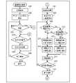
図3は、表示装置200の画像再生処理に関するフローチャートである。画像再生処理は、不揮発性メモリ203に記録されたプログラム(例えば、記録媒体208に記録されたVR画像のVR表示を行うための特定のアプリケーションプログラム)をメモリ202に展開してCPU201が実行することで実現される。電源ボタン206bが操作され表示装置200の電源がオンされると、CPU201は、フラグや制御変数等を初期化した後、画像再生処理を開始する。 FIG. 3 is a flowchart relating to the image reproduction process of the
ステップS301にて、CPU201は、記録媒体208に格納されているVR画像を取得し、当該VR画像の基準範囲(所定の表示範囲)を表示部205に表示する。本実施形態では、所定の表示方向である基準方向に関する情報がVR画像のメタデータに含まれている。表示方向は、VR表示のための向きであり、VR画像により形成されるVR空間の中心から表示範囲の中心に向かう向きである。そして、CPU201は、基準方向とVR画像に基づいて、基準方向が示す(指す)位置を中心とし且つ表示部205のサイズに対応するサイズを有する範囲を、基準範囲として表示部205に表示する。基準方向は、例えば、撮影時におけるデジタルカメラ100の姿勢に応じた方向である。具体的には、基準方向は、方位角度が前方カメラ部と後方カメラ部の一方(例えば前方カメラ部)の光軸と一致し、且つ、仰角が水平方向の角度となる位置を示す方向である。基準方向は、撮影時にデジタルカメラ100の正面が向けられた方向などでもよい。 In step S301, the
図4(A)は、天体(星空)を含むVR画像の一例である星空画像401を示す。星空画像401には、北極星402、その周辺の星403、北斗七星404、及び、山405が含まれている。図4(B)は、ステップS301で表示される画面の一例を示す。図4(B)の画面では、北斗七星404が表示されるように、星空画像401の一部の範囲が表示されている。表示対象が星空画像401であり且つ基準方向が北斗七星404の位置を示す場合に、ステップS301で図4(B)の画面が表示される。 FIG. 4A shows a
ステップS302にて、CPU201は、ステップS301で表示された画面に重ねてアニメーションボタン(VR画像を動かしながら表示するためのボタン)を表示する。図4(C)は、ステップS302で表示される画面の一例を示す。図4(C)の画面では、アニメーションボタン411~415を含むメニュー410が、図4(B)の画面に重ねて表示されている。アニメーションボタン411~415の間でVR画像の動かし方が異なる。アニメーションボタン414は、星空画像を意図した表示処理(星空画像に好適な動かし方で表示する処理;星空画像をより感動的に見せる動かし方で表示する処理)で表示するための星空アニメーションボタンである。 In step S302, the
ステップS303にて、CPU201は、操作部206に対して、星空アニメーションボタン414を選択する選択操作が行われたか否かを判定する。星空アニメーションボタン414の選択操作が行われた場合はステップS307へ進み、そうでなければステップS304へ進む。 In step S303, the
ステップS304にて、CPU201は、操作部206に対してその他の操作が行われたか否かを判定する。操作が行われた場合はステップS305へ進み、そうでなければステップS306へ進む。ステップS305にて、CPU201は、行われた操作に応じた処理(その他の処理)を行う。そして、ステップS306へ進む。例えば、タッチパネル206aに対するピンチ操作に応じて、表示されている画像の拡大や縮小などが行われたり、タッチパネル206aに対するスライド操作、表示装置200の姿勢変更、等に応じて、表示範囲が変更されたりする。また、アニメーションボタン411~413,415のいずれかを選択する選択操作に応じて、VR画像を動かしながら表示するアニメーション表示が行われたりもする。ステップS306にて、CPU201は、操作部206に対して終了操作(画像再生処理を終了するための操作)が行われたか否かを判定する。終了操作が行われた場合は画像再生処理を終了し、そうでなければステップS303へ進む。 In step S304, the
ステップS307~S317の処理について説明する。星空画像を動かしながら表示する場合に、実際の星の動きを再現するような動かし方で回転表示を行うと、ユーザー(観察者)により感動を与えられると期待できる。例えば、星空画像に北極星が含まれている場合には、北極星(特徴的な星)がある方向を自動的に表示すると感動的であり、北極星を中心として反時計回り(地球の自転に従った方向)に回転する回転表示を行うとより感動的である。ステップS307~S317の処理によれば、このような感動的な回転表示が実現できる。 The processing of steps S307 to S317 will be described. When displaying a starry sky image while moving it, it can be expected that the user (observer) will be impressed if the rotation display is performed in a way that reproduces the actual movement of the star. For example, if the starry sky image contains the North Star, it is impressive to automatically display the direction in which the North Star (characteristic star) is located, and it is counterclockwise around the North Star (following the rotation of the earth). It is more moving to perform a rotation display that rotates in the direction). According to the processes of steps S307 to S317, such a moving rotation display can be realized.
ステップS307にて、CPU201は、メニュー410の非表示、星空判定(後述)に使用するパターン画像(パターンデータ)の取得、等の初期化処理を行う。ステップS308にて、CPU201は、表示方向として基準方向を設定することで、表示範囲を基準範囲に変更する。ステップS305で表示範囲が基準範囲から変更される可能性があるため、ステップS308の処理を行う。ステップS308の処理を行うことで、ユーザーは常に同じ回転表示(基準範囲からの回転表示)を見ることができる。なお、ステップS308の処理を省略し、現在の表示範囲(視野)からの回転表示が行われるようにしてもよい。 In step S307, the
ステップS309にて、CPU201は、視野に星空(天体)のみが含まれているか否かを判定する。星空のみが含まれている場合はステップS310へ進み、そうでなければステップS311へ進む。本実施形態では、上述したパターン画像を用いたパターンマッチングにより、表示されているVR画像(少なくとも現在の表示範囲)から天体を検出し(天体検出)、天体検出の結果に基づいて、視野に星空のみが含まれているか否かを判定する。なお、VR画像の撮影モード、撮影時間、撮影方位(緯度と経度)、露出設定、等の撮影パラメータに基づいて判定を行ってもよい。 In step S309, the
ステップS310にて、CPU201は、視野に北極星が含まれているか否かを判定する。北極星が含まれている場合はステップS311へ進み、そうでなければステップS309へ進む。北極星が含まれているか否かは、例えば、天体検出の結果に基づいて判定される。 In step S310, the
ステップS311にて、CPU201は、VR画像を回転表示するための回転軸の方向として、VR空間の天頂方向を設定する。ステップS312にて、CPU201は、VR画像を回転表示するための回転方向として、時計回りの回転方向を設定する。 In step S311 the
ステップS313にて、CPU201は、北極星方向(VR空間において中心と北極星を通る方向)を検出し、VR画像を回転表示するための回転軸の方向として、北極星方向を設定する。北極星方向は、例えば、天体検出の結果に基づいて検出される。北極星方向の検出は「VR画像に含まれている天体が地球の自転によって回転する回転軸の検出(軸検出)」とも言える。ステップS314にて、CPU201は、VR画像を回転表示するための回転方向として、反時計回りの回転方向を設定する。 In step S313, the
なお、ステップS312,S314で設定される回転方向は上記回転方向に限られない。但し、ステップS314で反時計回りの回転方向を設定すれば、実際の星の動きと同じ動きを再現できる。また、ステップS312で設定される回転方向とステップS314で設定される回転方向を異ならせれば、回転軸のみを変化させる場合に比べ回転の変化がより大きくなるため、ユーザーにより感動を与えられると期待できる。 The rotation direction set in steps S312 and S314 is not limited to the above rotation direction. However, if the counterclockwise rotation direction is set in step S314, the same movement as the actual movement of the star can be reproduced. Further, if the rotation direction set in step S312 and the rotation direction set in step S314 are different, the change in rotation will be larger than in the case of changing only the rotation axis, and it is expected that the user will be impressed. can.
ステップS315において、CPU201は、設定されている回転軸に対応した位置を中心として、設定されている回転方向にVR画像を回転させながら表示するように、表示範囲を変更する(回転表示)。なお、回転速度は、一定速度であってもよいし、時間経過とともに減速または加速してもよい。 In step S315, the
ステップS316にて、CPU201は、ステップS315の回転表示が開始されてから所定時間が経過したか否かを判定する。所定時間が経過している場合はステップS317へ進み、そうでなければステップS309へ進む。ステップS317にて、CPU201は、再びメニュー410を表示するなどの終了処理(回転表示を終了する処理)を行う。 In step S316, the
表示対象が星空画像401(図4(A))である場合の表示画面(表示部205に表示された画面)の遷移について、図4(B)~4(G)を用いて説明する。図4(C)の画面が表示された状態で星空アニメーションボタン414が選択されると、ステップS307の処理によりメニュー410が非表示になり、ステップS308の処理により表示画面が図4(B)の画面(基準方向の画面)に遷移する。 The transition of the display screen (screen displayed on the display unit 205) when the display target is the starry sky image 401 (FIG. 4 (A)) will be described with reference to FIGS. 4 (B) to 4 (G). When the starry
図4(B)の画面では天体以外の被写体(山405)が視野に含まれているため、天頂方向の軸が回転軸として設定され(ステップS311)、時計回りの回転方向が設定され
る(ステップS312)。そして、設定された回転軸・回転方向での回転表示により、表示画面が図4(D)の画面に遷移する。図4(D)の画面でも天体以外の被写体(山405)が視野に含まれているため、回転軸・回転方向は変化せず、表示画面が図4(E)の画面に遷移する。図4(B),4(D),4(E)の画面遷移では、北斗七星404や山405が画面左側に移動する。なお、視野に天体のみが含まれているが北極星が含まれていない場合にも、同様の回転表示が行われる。Since the field of view includes a subject (mountain 405) other than the celestial body on the screen of FIG. 4B, the axis in the zenith direction is set as the rotation axis (step S311), and the clockwise rotation direction is set (step S311). Step S312). Then, the display screen transitions to the screen of FIG. 4D due to the rotation display in the set rotation axis / rotation direction. Even in the screen of FIG. 4 (D), since the subject (mountain 405) other than the celestial body is included in the field of view, the rotation axis / rotation direction does not change, and the display screen transitions to the screen of FIG. 4 (E). In the screen transitions of FIGS. 4 (B), 4 (D), and 4 (E), the
図4(E)の画面では、山405が視野から完全に消え、北極星402や、その周辺の星403のみが視野に含まれている。そのため、回転軸が天頂方向の軸から北極星方向の軸に切り替わり(ステップS313)、回転方向が時計回りの回転方向から反時計回りの回転方向に切り替わる(ステップS314)。そして、設定された回転軸・回転方向での回転表示により、表示画面が図4(F)の画面に遷移する。図4(F)の画面でも、北極星402や、その周辺の星403のみが視野に含まれているため、回転軸・回転方向は変化せず、表示画面が図4(G)の画面に遷移する。図4(E),4(F),4(G)の画面遷移では、北極星402の周辺の星403が北極星402を中心として反時計回りに回転する。 In the screen of FIG. 4 (E), the
以上述べたように、本実施形態によれば、表示対象画像に基づいて、表示対象画像に含まれている天体が地球の自転によって回転する回転軸が検出され、検出された回転軸で表示対象画像を回転させながら表示するように制御される。これにより、ユーザー(観察者)により感動を与えられると期待できる。 As described above, according to the present embodiment, the rotation axis in which the celestial body included in the display target image rotates due to the rotation of the earth is detected based on the display target image, and the display target is displayed on the detected rotation axis. The image is controlled to be displayed while being rotated. This can be expected to impress the user (observer).
なお、本実施形態では地球の北半球の星空を想定して北極星に着目したが、地球の南半球の星空を想定してポラリス・アウストラリス(はちぶんぎ座)に着目してもよい。CPU201は、表示対象画像に基づいて(例えば、天体を検出するパターンマッチングの結果、メタデータ、等に基づいて)、当該画像が地球の北半球と南半球のいずれでの撮影画像であるかを判定してもよい。そして、CPU201は、北半球の撮影画像は反時計回りに回転し、且つ、南半球の撮影画像は時計回りに回転するように、星空の回転表示を行ってもよい。具体的には、ステップS310にて、北極星またはポラリス・アウストラリスが表示範囲に含まれているか否かを判定してもよい。そして、ポラリス・アウストラリスが表示範囲に含まれていると判定された場合は、ステップS313にて、VR空間において中心とポラリス・アウストラリスを通る方向を設定し、ステップS314にて、時計回りの回転方向を設定してもよい。 In this embodiment, the North Star is focused on assuming the starry sky in the northern hemisphere of the earth, but Polaris Australis (Hachibungi) may be focused on assuming the starry sky in the southern hemisphere of the earth. Based on the image to be displayed (for example, based on the result of pattern matching for detecting celestial bodies, metadata, etc.), the
北極星やポラリス・アウストラリスが含まれていなくても、天体の位置関係、撮影場所(緯度と経度)、等に基づいて、自転軸(表示対象画像に含まれている天体が地球の自転によって回転する回転軸)は検出可能である。そのため、北極星やポラリス・アウストラリスが含まれているか否かにかかわらず、表示範囲に星空(天体)のみが含まれている場合に、自転軸を回転軸とする回転表示を行ってもよい。表示範囲に星空のみが含まれているか否かにかかわらず、自転軸を回転軸とする回転表示を行ってもよい。但し、表示範囲に星空のみが含まれていれば、星空のタイムラプス動画により近い感動的な表示を実現できる。 Even if the North Star and Polaris Australis are not included, the rotation axis (the celestial body included in the display target image rotates due to the rotation of the earth) based on the positional relationship of the celestial bodies, the shooting location (latitude and longitude), etc. The axis of rotation) is detectable. Therefore, regardless of whether or not the North Star and Polaris Australis are included, if only the starry sky (celestial body) is included in the display range, the rotation display with the rotation axis as the rotation axis may be performed. Regardless of whether or not only the starry sky is included in the display range, the rotation display with the rotation axis as the rotation axis may be performed. However, if only the starry sky is included in the display range, a moving display closer to the time-lapse movie of the starry sky can be realized.
北極星やポラリス・アウストラリスとは異なる特徴的な星や星座(特定の星や星座)などに着目してもよい。回転表示中にユーザー操作に応じて視野が変更可能であってもよい。星空の回転表示では、残像効果などの特殊効果が画像に付加されてもよい。 You may focus on characteristic stars and constellations (specific stars and constellations) that are different from the North Star and Polaris Australis. The field of view may be changeable according to the user operation during the rotation display. In the rotation display of the starry sky, special effects such as an afterimage effect may be added to the image.
ステップS310にて、特徴的な星や星座(例えば、北極星、ポラリス・アウストラリス、等)が「所定範囲(表示範囲の中央部など)」に含まれているか否かを判定してもよい。これにより、特徴的な星や星座が見やすい状態から星空の回転表示が開始される。例
えば、北極星をユーザーの正面にした星空の回転表示を行うことができるようになる。このため、ユーザーにより感動を与えられると期待できる。In step S310, it may be determined whether or not a characteristic star or constellation (for example, North Star, Polaris Australis, etc.) is included in the "predetermined range (central part of the display range, etc.)". As a result, the rotation display of the starry sky is started from the state where the characteristic stars and constellations are easy to see. For example, it will be possible to rotate the starry sky with the North Star in front of the user. Therefore, it can be expected that the user will be impressed.
表示対象画像の全体から特徴的な星や星座を検出し、検出位置の方向に表示方向を徐々に近づけ、検出位置が表示範囲に入ったことに応じて自転軸を回転軸とする回転表示を開始してもよい。表示対象画像の全体から特徴的な星や星座を検出し、検出位置の方向に表示方向を一度に変更し、自転軸を回転軸とする回転表示を開始してもよい。 Characteristic stars and constellations are detected from the entire display target image, the display direction is gradually moved closer to the direction of the detection position, and the rotation display with the rotation axis as the rotation axis is displayed according to the detection position entering the display range. You may start. Characteristic stars and constellations may be detected from the entire display target image, the display direction may be changed at once in the direction of the detection position, and rotation display with the rotation axis as the rotation axis may be started.
なお、CPU201が行うものとして説明した上述の各種制御は、1つのハードウェアが行ってもよいし、複数のハードウェア(例えば、複数のプロセッサーや回路)が処理を分担することで、装置全体の制御を行ってもよい。 The above-mentioned various controls described as those performed by the
また、本発明をその好適な実施形態に基づいて詳述してきたが、本発明はこれら特定の実施形態に限られるものではなく、この発明の要旨を逸脱しない範囲の様々な形態も本発明に含まれる。さらに、上述した各実施形態は本発明の一実施形態を示すものにすぎず、各実施形態を適宜組み合わせることも可能である。 Further, although the present invention has been described in detail based on the preferred embodiment thereof, the present invention is not limited to these specific embodiments, and various embodiments within the range not deviating from the gist of the present invention are also included in the present invention. included. Further, each of the above-described embodiments is merely an embodiment of the present invention, and each embodiment can be appropriately combined.
また、上述した実施形態においては、本発明を表示装置に適用した場合を例にして説明したが、本発明はこの例に限定されず画像を表示部に表示するように制御可能な表示制御装置であれば適用可能である。例えば、本発明は、パーソナルコンピュータやPDA、携帯電話端末や携帯型の画像ビューワ、プリンタ装置、デジタルフォトフレーム、音楽プレーヤー、ゲーム機、電子ブックリーダー、映像プレーヤーなどに適用可能である。また、本発明は、テレビジョン装置、投影装置、タブレット端末、スマートフォン、AIスピーカー、家電装置、車載装置、医療機器などにも適用可能である。 Further, in the above-described embodiment, the case where the present invention is applied to the display device has been described as an example, but the present invention is not limited to this example and the display control device can be controlled so as to display an image on the display unit. If so, it is applicable. For example, the present invention can be applied to a personal computer, a PDA, a mobile phone terminal, a portable image viewer, a printer device, a digital photo frame, a music player, a game machine, an electronic book reader, a video player, and the like. The present invention can also be applied to television devices, projection devices, tablet terminals, smartphones, AI speakers, home appliances, in-vehicle devices, medical devices and the like.
(その他の実施形態)
本発明は、上述の実施形態の1以上の機能を実現するプログラムを、ネットワーク又は記憶媒体を介してシステム又は装置に供給し、そのシステム又は装置のコンピュータにおける1つ以上のプロセッサーがプログラムを読出し実行する処理でも実現可能である。また、1以上の機能を実現する回路(例えば、ASIC)によっても実現可能である。(Other embodiments)
The present invention supplies a program that realizes one or more functions of the above-described embodiment to a system or device via a network or storage medium, and one or more processors in the computer of the system or device reads and executes the program. It can also be realized by the processing to be performed. It can also be realized by a circuit (for example, ASIC) that realizes one or more functions.
200:表示装置 201:CPU 200: Display device 201: CPU
Claims (10)
Translated fromJapanese前記画像における、前記軸検出手段で検出された回転軸に対応した位置を中心に前記画像を回転させながら表示するよう制御する制御手段と、
を有することを特徴とする表示制御装置。Based on the image, an axis detecting means for detecting the axis of rotation in which the celestial body contained in the image rotates due to the rotation of the earth, and
A control means for controlling the image to be displayed while rotating around a position corresponding to the rotation axis detected by the axis detection means in the image.
A display control device characterized by having.
前記制御手段は、前記第1判定手段によって前記画像が前記北半球での撮影画像であると判定された場合は第1の回転方向で前記画像を回転させながら表示し、前記画像が前記南半球での撮影画像であると判定された場合は第2の回転方向で前記画像を回転させながら表示するよう制御する
ことを特徴とする請求項1に記載の表示制御装置。Further, it has a first determination means for determining whether the image is a photographed image in the northern hemisphere or the southern hemisphere of the earth based on the image.
When the first determination means determines that the image is a captured image in the northern hemisphere, the control means displays the image while rotating it in the first rotation direction, and the image is displayed in the southern hemisphere. The display control device according to claim 1, wherein when it is determined that the image is a captured image, the image is controlled to be displayed while being rotated in the second rotation direction.
ことを特徴とする請求項2に記載の表示制御装置。The display control device according to claim 2, wherein the first rotation direction is a counterclockwise direction.
前記表示制御装置は、前記表示範囲に天体のみが含まれているか否かを判定する第2判定手段、をさらに有し、
前記制御手段は、前記第2判定手段によって前記表示範囲に天体のみが含まれていると判定された場合に、前記軸検出手段で検出された回転軸に対応した位置を中心に前記画像を回転させながら表示するための制御を行い、前記表示範囲に天体以外の被写体が含まれていると判定された場合に、前記制御を行わない
ことを特徴とする請求項1~3のいずれか1項に記載の表示制御装置。The control means controls to display a part of the range of the image as a display range, and controls the display.
The display control device further includes a second determination means for determining whether or not only a celestial body is included in the display range.
When it is determined by the second determination means that only the celestial body is included in the display range, the control means rotates the image around the position corresponding to the rotation axis detected by the axis detection means. Any one of claims 1 to 3, wherein the control for displaying the image is performed while the control is performed, and the control is not performed when it is determined that the display range includes a subject other than the celestial body. The display control device described in.
前記制御手段は、前記第2判定手段によって前記表示範囲に天体のみが含まれており且つ前記表示範囲に北極星またはポラリス・アウストラリスが含まれていると判定された場合に、前記制御を行い、前記表示範囲に天体のみが含まれているが前記表示範囲に北極星もポラリス・アウストラリスも含まれていないと判定された場合に、前記制御を行わないことを特徴とする請求項4に記載の表示制御装置。The second determination means further determines whether or not the display range includes the North Star or Polaris Australis.
The control means performs the control when it is determined by the second determination means that only the celestial body is included in the display range and the North Star or Polaris Australis is included in the display range. The display control according to claim 4, wherein when it is determined that the display range includes only celestial bodies but neither the North Star nor Polaris Australis is included in the display range, the control is not performed. Device.
前記軸検出手段は、前記天体検出手段の検出結果に基づいて前記回転軸を検出する
ことを特徴とする請求項1~5のいずれか1項に記載の表示制御装置。Further, it has an astronomical object detecting means for detecting an astronomical object from the image by pattern matching.
The display control device according to any one of claims 1 to 5, wherein the axis detecting means detects the rotating shaft based on the detection result of the celestial body detecting means.
前記画像の一部の範囲を表示範囲として表示するよう制御し、
前記軸検出手段で検出された回転軸に対応した位置を中心に前記画像を回転させながら表示するように、前記表示範囲を変更する
ことを特徴とする請求項1~6のいずれか1項に記載の表示制御装置。The control means is
Controlled to display a part of the range of the image as a display range,
The invention according to any one of claims 1 to 6, wherein the display range is changed so that the image is displayed while rotating around the position corresponding to the rotation axis detected by the axis detecting means. The display control device described.
前記画像における、検出された回転軸に対応した位置を中心に前記画像を回転させなが
ら表示するよう制御するステップと、
を有することを特徴とする表示制御方法。Based on the image, the step of detecting the axis of rotation of the celestial body contained in the image due to the rotation of the earth, and
A step of controlling the image to be displayed while rotating around the position corresponding to the detected rotation axis in the image, and a step of controlling the image to be displayed while rotating.
A display control method characterized by having.
Priority Applications (3)
| Application Number | Priority Date | Filing Date | Title |
|---|---|---|---|
| JP2018130846AJP7086762B2 (en) | 2018-07-10 | 2018-07-10 | Display control device |
| US16/460,031US11049220B2 (en) | 2018-07-10 | 2019-07-02 | Display control apparatus, display control method, and non-transitory computer readable medium |
| CN201910621173.8ACN110708459B (en) | 2018-07-10 | 2019-07-10 | Display control apparatus, display control method, and computer-readable medium |
Applications Claiming Priority (1)
| Application Number | Priority Date | Filing Date | Title |
|---|---|---|---|
| JP2018130846AJP7086762B2 (en) | 2018-07-10 | 2018-07-10 | Display control device |
Publications (2)
| Publication Number | Publication Date |
|---|---|
| JP2020010227A JP2020010227A (en) | 2020-01-16 |
| JP7086762B2true JP7086762B2 (en) | 2022-06-20 |
Family
ID=69138443
Family Applications (1)
| Application Number | Title | Priority Date | Filing Date |
|---|---|---|---|
| JP2018130846AActiveJP7086762B2 (en) | 2018-07-10 | 2018-07-10 | Display control device |
Country Status (3)
| Country | Link |
|---|---|
| US (1) | US11049220B2 (en) |
| JP (1) | JP7086762B2 (en) |
| CN (1) | CN110708459B (en) |
Citations (3)
| Publication number | Priority date | Publication date | Assignee | Title |
|---|---|---|---|---|
| JP2006287375A (en) | 2005-03-31 | 2006-10-19 | Casio Comput Co Ltd | Imaging apparatus and program |
| JP2012005112A (en) | 2010-05-19 | 2012-01-05 | Hoya Corp | Astronomical object automatic tracking photographic method and camera |
| JP2016019231A (en) | 2014-07-10 | 2016-02-01 | オリンパス株式会社 | Imaging apparatus, and control method of imaging apparatus |
Family Cites Families (7)
| Publication number | Priority date | Publication date | Assignee | Title |
|---|---|---|---|---|
| US5902113A (en)* | 1996-08-07 | 1999-05-11 | C. Robert Pryor | Map and calculator device |
| JP2011040898A (en) | 2009-08-07 | 2011-02-24 | Casio Computer Co Ltd | Imaging reproducing device and program |
| CN102706363B (en) | 2012-05-25 | 2015-04-15 | 清华大学 | Precision measuring method of high-precision star sensor |
| KR102191082B1 (en)* | 2014-08-28 | 2020-12-15 | 엘지디스플레이 주식회사 | In plane switching mode liquid crystal display device having optical compensation film |
| US10228766B2 (en) | 2014-09-12 | 2019-03-12 | Microsoft Technology Licensing, Llc | Enhanced Display Rotation |
| KR20170014556A (en)* | 2015-07-30 | 2017-02-08 | 삼성전자주식회사 | Method and photographing device for photographing a moving object |
| JP7139584B2 (en)* | 2017-08-17 | 2022-09-21 | ソニーグループ株式会社 | Information processing device, information processing method, program, and information processing system |
- 2018
- 2018-07-10JPJP2018130846Apatent/JP7086762B2/enactiveActive
- 2019
- 2019-07-02USUS16/460,031patent/US11049220B2/enactiveActive
- 2019-07-10CNCN201910621173.8Apatent/CN110708459B/enactiveActive
Patent Citations (3)
| Publication number | Priority date | Publication date | Assignee | Title |
|---|---|---|---|---|
| JP2006287375A (en) | 2005-03-31 | 2006-10-19 | Casio Comput Co Ltd | Imaging apparatus and program |
| JP2012005112A (en) | 2010-05-19 | 2012-01-05 | Hoya Corp | Astronomical object automatic tracking photographic method and camera |
| JP2016019231A (en) | 2014-07-10 | 2016-02-01 | オリンパス株式会社 | Imaging apparatus, and control method of imaging apparatus |
Also Published As
| Publication number | Publication date |
|---|---|
| JP2020010227A (en) | 2020-01-16 |
| US20200020081A1 (en) | 2020-01-16 |
| CN110708459B (en) | 2022-06-14 |
| CN110708459A (en) | 2020-01-17 |
| US11049220B2 (en) | 2021-06-29 |
Similar Documents
| Publication | Publication Date | Title |
|---|---|---|
| JP7094815B2 (en) | Display control device, control method of display control device, program, storage medium | |
| CN110691187B (en) | Electronic device, control method of electronic device, and computer-readable medium | |
| CN111385470B (en) | Electronic device, control method of electronic device, and computer-readable medium | |
| US11295530B2 (en) | Electronic apparatus for playing back a virtual reality video image and control method therefor | |
| US11380075B2 (en) | Electronic apparatus for playing back a virtual reality video image and control method therefor | |
| JP2020042064A (en) | Display control device, imaging device, control method, program, and storage medium | |
| US11079898B2 (en) | Electronic device for controlling display of VR image, control method of electronic device, and non-transitory computer readable medium | |
| JP7204511B2 (en) | Electronic device, electronic device control method, program | |
| JP7267764B2 (en) | ELECTRONIC DEVICE, ELECTRONIC DEVICE CONTROL METHOD, PROGRAM, AND STORAGE MEDIUM | |
| JP2021174317A (en) | Electronic devices and their control methods | |
| US11558599B2 (en) | Electronic apparatus, control method for electronic apparatus, and non-transitory computer-readable storage medium | |
| JP7086762B2 (en) | Display control device | |
| JP2021069045A (en) | Display control device, display control method, program, and storage media | |
| JP7336200B2 (en) | Electronic device and its control method | |
| CN110881102B (en) | Image capturing apparatus, control method of image capturing apparatus, and computer readable medium | |
| JP2024116858A (en) | Electronic device, electronic device control method, program, and storage medium | |
| JP2020205554A (en) | Display control device, control method of the same, program, and storage medium |
Legal Events
| Date | Code | Title | Description |
|---|---|---|---|
| RD02 | Notification of acceptance of power of attorney | Free format text:JAPANESE INTERMEDIATE CODE: A7422 Effective date:20181116 | |
| A621 | Written request for application examination | Free format text:JAPANESE INTERMEDIATE CODE: A621 Effective date:20210708 | |
| A977 | Report on retrieval | Free format text:JAPANESE INTERMEDIATE CODE: A971007 Effective date:20220425 | |
| TRDD | Decision of grant or rejection written | ||
| A01 | Written decision to grant a patent or to grant a registration (utility model) | Free format text:JAPANESE INTERMEDIATE CODE: A01 Effective date:20220510 | |
| A61 | First payment of annual fees (during grant procedure) | Free format text:JAPANESE INTERMEDIATE CODE: A61 Effective date:20220608 | |
| R151 | Written notification of patent or utility model registration | Ref document number:7086762 Country of ref document:JP Free format text:JAPANESE INTERMEDIATE CODE: R151 |