JP7086619B2 - Endoscopic surgical clip applier - Google Patents
Endoscopic surgical clip applierDownload PDFInfo
- Publication number
- JP7086619B2 JP7086619B2JP2018013576AJP2018013576AJP7086619B2JP 7086619 B2JP7086619 B2JP 7086619B2JP 2018013576 AJP2018013576 AJP 2018013576AJP 2018013576 AJP2018013576 AJP 2018013576AJP 7086619 B2JP7086619 B2JP 7086619B2
- Authority
- JP
- Japan
- Prior art keywords
- rack
- pawl
- trigger
- assembly
- release switch
- Prior art date
- Legal status (The legal status is an assumption and is not a legal conclusion. Google has not performed a legal analysis and makes no representation as to the accuracy of the status listed.)
- Active
Links
- 238000002674endoscopic surgeryMethods0.000claimsdescription7
- 238000001356surgical procedureMethods0.000claimsdescription2
- 208000019300CLIPPERSDiseases0.000claims1
- 208000021930chronic lymphocytic inflammation with pontine perivascular enhancement responsive to steroidsDiseases0.000claims1
- 238000000034methodMethods0.000description7
- 238000013189cholangiographyMethods0.000description3
- 239000012530fluidSubstances0.000description2
- 238000012978minimally invasive surgical procedureMethods0.000description2
- 230000003213activating effectEffects0.000description1
- 230000000712assemblyEffects0.000description1
- 238000000429assemblyMethods0.000description1
- 230000015572biosynthetic processEffects0.000description1
- 230000006835compressionEffects0.000description1
- 238000007906compressionMethods0.000description1
- 238000010276constructionMethods0.000description1
- 238000012976endoscopic surgical procedureMethods0.000description1
- 239000000945fillerSubstances0.000description1
- 238000010304firingMethods0.000description1
- 230000005484gravityEffects0.000description1
- 238000002324minimally invasive surgeryMethods0.000description1
- 238000012986modificationMethods0.000description1
- 230000004048modificationEffects0.000description1
- 239000004033plasticSubstances0.000description1
- 229920003023plasticPolymers0.000description1
- 229920000642polymerPolymers0.000description1
- 229910001220stainless steelInorganic materials0.000description1
- 239000010935stainless steelSubstances0.000description1
- 239000012815thermoplastic materialSubstances0.000description1
- 238000013519translationMethods0.000description1
- 230000014616translationEffects0.000description1
Images


Classifications
- A—HUMAN NECESSITIES
- A61—MEDICAL OR VETERINARY SCIENCE; HYGIENE
- A61B—DIAGNOSIS; SURGERY; IDENTIFICATION
- A61B17/00—Surgical instruments, devices or methods
- A61B17/12—Surgical instruments, devices or methods for ligaturing or otherwise compressing tubular parts of the body, e.g. blood vessels or umbilical cord
- A61B17/128—Surgical instruments, devices or methods for ligaturing or otherwise compressing tubular parts of the body, e.g. blood vessels or umbilical cord for applying or removing clamps or clips
- A61B17/1285—Surgical instruments, devices or methods for ligaturing or otherwise compressing tubular parts of the body, e.g. blood vessels or umbilical cord for applying or removing clamps or clips for minimally invasive surgery
- A—HUMAN NECESSITIES
- A61—MEDICAL OR VETERINARY SCIENCE; HYGIENE
- A61B—DIAGNOSIS; SURGERY; IDENTIFICATION
- A61B17/00—Surgical instruments, devices or methods
- A61B17/12—Surgical instruments, devices or methods for ligaturing or otherwise compressing tubular parts of the body, e.g. blood vessels or umbilical cord
- A61B17/122—Clamps or clips, e.g. for the umbilical cord
- A—HUMAN NECESSITIES
- A61—MEDICAL OR VETERINARY SCIENCE; HYGIENE
- A61B—DIAGNOSIS; SURGERY; IDENTIFICATION
- A61B17/00—Surgical instruments, devices or methods
- A61B17/28—Surgical forceps
- A61B17/2812—Surgical forceps with a single pivotal connection
- A61B17/282—Jaws
- A—HUMAN NECESSITIES
- A61—MEDICAL OR VETERINARY SCIENCE; HYGIENE
- A61B—DIAGNOSIS; SURGERY; IDENTIFICATION
- A61B1/00—Instruments for performing medical examinations of the interior of cavities or tubes of the body by visual or photographical inspection, e.g. endoscopes; Illuminating arrangements therefor
- A61B1/313—Instruments for performing medical examinations of the interior of cavities or tubes of the body by visual or photographical inspection, e.g. endoscopes; Illuminating arrangements therefor for introducing through surgical openings, e.g. laparoscopes
- A61B1/3132—Instruments for performing medical examinations of the interior of cavities or tubes of the body by visual or photographical inspection, e.g. endoscopes; Illuminating arrangements therefor for introducing through surgical openings, e.g. laparoscopes for laparoscopy
- A—HUMAN NECESSITIES
- A61—MEDICAL OR VETERINARY SCIENCE; HYGIENE
- A61B—DIAGNOSIS; SURGERY; IDENTIFICATION
- A61B17/00—Surgical instruments, devices or methods
- A61B2017/00367—Details of actuation of instruments, e.g. relations between pushing buttons, or the like, and activation of the tool, working tip, or the like
- A61B2017/00407—Ratchet means
- A—HUMAN NECESSITIES
- A61—MEDICAL OR VETERINARY SCIENCE; HYGIENE
- A61B—DIAGNOSIS; SURGERY; IDENTIFICATION
- A61B17/00—Surgical instruments, devices or methods
- A61B17/12—Surgical instruments, devices or methods for ligaturing or otherwise compressing tubular parts of the body, e.g. blood vessels or umbilical cord
- A61B2017/12004—Surgical instruments, devices or methods for ligaturing or otherwise compressing tubular parts of the body, e.g. blood vessels or umbilical cord for haemostasis, for prevention of bleeding
- A—HUMAN NECESSITIES
- A61—MEDICAL OR VETERINARY SCIENCE; HYGIENE
- A61B—DIAGNOSIS; SURGERY; IDENTIFICATION
- A61B17/00—Surgical instruments, devices or methods
- A61B17/28—Surgical forceps
- A61B17/29—Forceps for use in minimally invasive surgery
- A61B2017/2926—Details of heads or jaws
- A61B2017/2927—Details of heads or jaws the angular position of the head being adjustable with respect to the shaft
- A61B2017/2929—Details of heads or jaws the angular position of the head being adjustable with respect to the shaft with a head rotatable about the longitudinal axis of the shaft
- A—HUMAN NECESSITIES
- A61—MEDICAL OR VETERINARY SCIENCE; HYGIENE
- A61B—DIAGNOSIS; SURGERY; IDENTIFICATION
- A61B17/00—Surgical instruments, devices or methods
- A61B17/28—Surgical forceps
- A61B17/29—Forceps for use in minimally invasive surgery
- A61B2017/2926—Details of heads or jaws
- A61B2017/2932—Transmission of forces to jaw members
- A61B2017/2939—Details of linkages or pivot points
- A61B2017/294—Connection of actuating rod to jaw, e.g. releasable
- A—HUMAN NECESSITIES
- A61—MEDICAL OR VETERINARY SCIENCE; HYGIENE
- A61B—DIAGNOSIS; SURGERY; IDENTIFICATION
- A61B90/00—Instruments, implements or accessories specially adapted for surgery or diagnosis and not covered by any of the groups A61B1/00 - A61B50/00, e.g. for luxation treatment or for protecting wound edges
- A61B90/08—Accessories or related features not otherwise provided for
- A61B2090/0807—Indication means
Landscapes
- Health & Medical Sciences (AREA)
- Surgery (AREA)
- Life Sciences & Earth Sciences (AREA)
- Heart & Thoracic Surgery (AREA)
- Molecular Biology (AREA)
- Veterinary Medicine (AREA)
- Engineering & Computer Science (AREA)
- Biomedical Technology (AREA)
- Public Health (AREA)
- Medical Informatics (AREA)
- Nuclear Medicine, Radiotherapy & Molecular Imaging (AREA)
- Animal Behavior & Ethology (AREA)
- General Health & Medical Sciences (AREA)
- Reproductive Health (AREA)
- Vascular Medicine (AREA)
- Ophthalmology & Optometry (AREA)
- Surgical Instruments (AREA)
Description
Translated fromJapanese関連出願の相互参照
本出願は、2017年2月6日に出願された米国仮特許出願第62/455,090号の利益及び優先権を主張し、その開示全体は、参照により本明細書に組み込まれる。
背景Cross-reference to related applications This application claims the interests and priorities of US Provisional Patent Application No. 62 / 455,090 filed February 6, 2017, the entire disclosure of which is hereby incorporated by reference. Be incorporated.
background
本開示は概して、外科用クリップアプライヤに関する。より具体的には、本開示は、内視鏡的外科用クリップアプライヤのラチェットアセンブリのための解除スイッチを有する内視鏡的外科用クリップアプライヤに関する。 The present disclosure relates generally to surgical clip appliers. More specifically, the present disclosure relates to an endoscopic surgical clip applier having a release switch for the ratchet assembly of the endoscopic surgical clip applier.
内視鏡的外科用ステープラ及び外科用クリップアプライヤは、いくつかの低侵襲または内視鏡の外科的処置のために使用される。典型的に、低侵襲外科手術では、チューブまたはカニューレ装置が、アクセスポートを提供するための入口切開を通って患者の体に伸展される。このポートは、切開部から離れて除去される外科的処置を行うためのいくつかの異なる外科用器具を、外科医がそのポートを通して挿入することを可能にする。 Endoscopic surgical staplers and surgical clip appliers are used for some minimally invasive or endoscopic surgical procedures. Typically, in minimally invasive surgery, a tube or cannula device is extended to the patient's body through an entrance incision to provide an access port. This port allows the surgeon to insert several different surgical instruments through the port for performing surgical procedures that are removed away from the incision.
内視鏡的外科用クリップアプライヤは、低侵襲外科的処置中に単一または複数の外科用クリップを適用することができる。外科用クリップの適用は通常、脈管上でクリップを圧縮することを伴う。脈管に適用されたら、圧縮された外科用クリップは、そこを通る流体の流れを終わらせる。脈管を通る流体の流れを終わらせることは、典型的に、外科用クリップの完全な形成を必要とする。 Endoscopic surgical clip appliers can apply single or multiple surgical clips during minimally invasive surgical procedures. Application of surgical clips usually involves compressing the clip on the vessel. Once applied to the vessel, the compressed surgical clip ends the flow of fluid through it. Ending the flow of fluid through the vessel typically requires the complete formation of a surgical clip.
ある特定の内視鏡処置中に、クリップを部分的に形成することが望ましく、かつ/または必要である場合がある。例えば、部分的に形成されたクリップは、胆管造影または他の医療処置中に組織の周囲にカテーテルを固定するために使用され得る。 It may be desirable and / or necessary to partially form a clip during certain endoscopic procedures. For example, a partially formed clip can be used to secure a catheter around the tissue during cholangiography or other medical procedures.
したがって、臨床医に外科用クリップを部分的に形成する簡便な手段を提供する内視鏡的外科用クリップアプライヤの必要性が存在する。 Therefore, there is a need for endoscopic surgical clip appliers that provide clinicians with a convenient means of partially forming surgical clips.
本開示は、臨床医が外科的クリップを部分的にまたは完全に形成するかを選択することを可能にする内視鏡的外科用クリップアプライヤに関する。 The present disclosure relates to an endoscopic surgical clip applier that allows a clinician to choose whether to form a surgical clip partially or completely.
本開示の態様に従って、内視鏡的外科用クリップアプライヤは、内視鏡アセンブリ及びハンドルアセンブリを含む。内視鏡的アセンブリは、シャフトアセンブリ、及びシャフトアセンブリに動作可能に連結し、そこから延在する一対のジョー部材を含む。ハンドルアセンブリは、内視鏡的アセンブリに選択的に接続可能なハウジングを含む。固定されたハンドルは、ハウジングから延在し、トリガは、固定されたハンドルに枢動可能に接続される。駆動バーは、ハンドルアセンブリのハウジング内に配置され、トリガの作動時に、離間構成と接近構成との間で一対のジョー部材を移動させるように、トリガに、及び一対のジョー部材に動作可能に連結される。ラチェットアセンブリも、ハンドルアセンブリのハウジング内に配置される。ラチェットアセンブリは、駆動バーに動作可能に連結される第1のラックを含む。第1のラックは、複数の第1のラック歯を画定し、かつ遠位端及び近位端を有し、第1のラックの遠位端と近位端との間の第1の長さを含む。第2のラックは、第1のラックから間隙を介して駆動バーに動作可能に連結される。第2のラックは、複数の第2のラック歯を画定し、かつ遠位端及び近位端を有し、第2のラックの遠位端と近位端との間の第2の長さを含む。第2のラックの第2の長さは、第1のラックの第1のラックの第1の長さ未満である。 According to aspects of the present disclosure, endoscopic surgical clip appliers include an endoscopic assembly and a handle assembly. The endoscopic assembly includes a shaft assembly and a pair of jaw members operably connected to and extending from the shaft assembly. The handle assembly includes a housing that can be selectively connected to the endoscopic assembly. The fixed handle extends from the housing and the trigger is pivotally connected to the fixed handle. The drive bar is located within the housing of the handle assembly and is operably coupled to the trigger and to the pair of jaw members to move the pair of jaw members between the separated and close configurations when the trigger is activated. Will be done. The ratchet assembly is also placed inside the housing of the handle assembly. The ratchet assembly includes a first rack that is operably coupled to the drive bar. The first rack defines a plurality of first rack teeth and has a distal end and a proximal end, the first length between the distal and proximal ends of the first rack. including. The second rack is operably connected to the drive bar from the first rack via a gap. The second rack defines a plurality of second rack teeth and has a distal end and a proximal end, a second length between the distal and proximal ends of the second rack. including. The second length of the second rack is less than the first length of the first rack of the first rack.
実施形態において、ラチェットアセンブリは、ハンドルアセンブリのハウジング内に取り付けられた第1の歯止めをさらに含み、第1の歯止めは、その第1の位置で第1のラックの複数の第1のラック歯と選択的に係合可能である。 In an embodiment, the ratchet assembly further comprises a first pawl mounted within the housing of the handle assembly, the first pawl with a plurality of first rack teeth of the first rack in its first position. It can be selectively engaged.
実施形態において、ラチェットアセンブリは、ハンドルアセンブリのハウジング内に取り付けられた第2の歯止めをさらに含み、第2の歯止めは、その第1の位置で第2のラックの複数の第2のラック歯と選択的に係合可能である。 In an embodiment, the ratchet assembly further comprises a second pawl mounted within the housing of the handle assembly, the second pawl with a plurality of second rack teeth of the second rack in its first position. It can be selectively engaged.
実施形態において、ラチェットアセンブリは、第1のラックの遠位端に隣接して配置される遠位ウェルをさらに含み、第1の歯止めは、トリガの非作動位置において遠位ウェル内に位置する。 In an embodiment, the ratchet assembly further comprises a distal well located adjacent to the distal end of the first rack, the first pawl is located within the distal well in the non-actuated position of the trigger.
いくつかの実施形態において、ラチェットアセンブリは、第1のラックの近位端と第2のラックの遠位端との間に配置される近位ウェルをさらに含み、第2の歯止めは、トリガの非作動位置において近位ウェル内に位置する。 In some embodiments, the ratchet assembly further comprises a proximal well located between the proximal end of the first rack and the distal end of the second rack, the second pawl of the trigger. Located in the proximal well in the non-actuated position.
実施形態において、第1のラックは、第2のラックの遠位の位置に配置される。 In embodiments, the first rack is located distal to the second rack.
実施形態において、ラチェットアセンブリは、ハンドルアセンブリのハウジング内に少なくとも部分的に支持され、第1の歯止めと動作可能に関連付けられた解除スイッチをさらに含む。解除スイッチは、第1の位置から第1の歯止めを移動させるように選択的に作動可能であり、第1の歯止めは、第2の位置へと第1のラックの複数の第1のラック歯と位置合わせされ、第1の歯止めは、第1のラックの複数の第1のラック歯との位置合わせから外れる。 In embodiments, the ratchet assembly further comprises a release switch that is at least partially supported within the housing of the handle assembly and is operably associated with a first pawl. The release switch can be selectively actuated to move the first pawl from the first position, and the first pawl is a plurality of first rack teeth of the first rack to the second position. The first pawl is out of alignment with the plurality of first rack teeth of the first rack.
いくつかの実施形態において、解除スイッチが作動されるとき、第2の歯止めは、第2の歯止めが近位ウェル内に配置されるまで、または第2の歯止めが第2のラックの近位端を越えて近位に配置されるまで、その第1の位置において、第2のラックの複数の第2のラック歯との位置合わせを維持する。 In some embodiments, when the release switch is activated, the second stop is until the second stop is placed in the proximal well, or the second stop is at the proximal end of the second rack. In its first position, the alignment of the second rack with the plurality of second rack teeth is maintained until it is located proximally beyond.
いくつかの実施形態において、駆動バーは、トリガが作動されると長手方向に移動可能であり、駆動バーは、第1の方向に長手方向に移動され、解除スイッチは作動されないとき、第2の反対の方向への駆動バーの長手方向の移動が、第1の歯止めが遠位ウェル内に配置され、第2の歯止めが近位ウェル内に配置されるまで、または第1の歯止めが第1のラックの近位端に配置され、第2の歯止めが第2のラックの近位端を超えて近位に配置されるまで、妨げられるように、第1の歯止め及び第2の歯止めは、第1及び第2のラックの複数の第1のラック歯及び複数の第2のラック歯上をそれぞれ移動される。 In some embodiments, the drive bar is longitudinally movable when the trigger is activated, the drive bar is longitudinally moved in the first direction, and a second release switch is not activated. Longitudinal movement of the drive bar in the opposite direction until the first pawl is placed in the distal well and the second pawl is placed in the proximal well, or the first pawl is the first. The first and second pawls are placed so that they are placed at the proximal end of the rack and are blocked until the second pawl is located proximally beyond the proximal end of the second rack. It is moved on the plurality of first rack teeth and the plurality of second rack teeth of the first and second racks, respectively.
実施形態において、駆動バーは、トリガが作動されると、長手方向に移動可能であり、駆動バーが第1の方向に長手方向に移動され、解除スイッチが作動されて第1の歯止めを移動させて第1のラックの複数の第1のラック歯との位置合わせから外すとき、第2の、反対方向への駆動バーの長手方向の移動は、第2の歯止めが近位ウェル内に配置されるまで、または第2の歯止めが第2のラックの近位端を超えて近位に配置されるまで妨げられる。 In embodiments, the drive bar is longitudinally movable when the trigger is actuated, the drive bar is longitudinally moved in the first direction, and the release switch is actuated to move the first pawl. When disaligning the first rack with the plurality of first rack teeth, the longitudinal movement of the drive bar in the second, opposite direction, the second pawl is placed in the proximal well. It is blocked until or until the second pawl is placed proximally beyond the proximal end of the second rack.
実施形態において、駆動バーが第1の方向に長手方向に移動され、解除スイッチが作動されて第1の歯止めを移動させて第1のラックの複数の第1のラック歯との位置合わせから外すとき、第2の歯止めは、トリガが部分的に作動された位置に達するとき、第2のラックの近位端を超えて配置され、駆動バーは、トリガが部分的に作動された位置から完全に非作動位置に達したとき、第2の、反対方向に長手方向に移動可能である。 In embodiments, the drive bar is moved longitudinally in the first direction and the release switch is actuated to move the first pawl out of alignment with the plurality of first rack teeth of the first rack. When the second pawl is placed beyond the proximal end of the second rack when the trigger reaches the partially actuated position, the drive bar is fully from the partially actuated position of the trigger. When it reaches the non-actuated position, it can move in the second, longitudinal direction in the opposite direction.
内視鏡的アセンブリは、シャフトアセンブリ内に摺動自在に配置され、一対のジョー部材の間に選択的に形成可能な複数の外科用クリップをさらに含み、第1の歯止めが第1の位置にあるとき、第1の歯止めは、トリガの作動時に、トリガが完全駆動位置に移動され、複数の外科用クリップの最遠位の外科用クリップが一対のジョー部材の間に完全に形成されるまで、トリガがその移動の方向を逆転できないように、駆動バー上に配置された第1のラックと位置合わせされる。 The endoscopic assembly is slidably located within the shaft assembly and further includes multiple surgical clips that can be selectively formed between a pair of jaw members, with the first pawl in the first position. At one point, the first pawl is until the trigger is moved to the fully driven position when the trigger is activated and the most distal surgical clip of the plurality of surgical clips is completely formed between the pair of jaw members. , The trigger is aligned with a first rack located on the drive bar so that the direction of movement cannot be reversed.
いくつかの実施形態では、第1の歯止めハウジングが第2の位置にあるとき、第1の歯止めは、複数の外科用クリップの最遠位の外科用クリップが一対のジョー部材の間に部分的に形成されるように、第2の歯止めが第2のラックの近位端を越えて配置され、トリガが部分的作動位置に移動されるときに、トリガがその移動の方向を逆転させることができるように、駆動バー上に配置された第1のラックとの位置合わせから外れる。 In some embodiments, when the first pawl housing is in the second position, the first pawl is such that the most distal surgical clip of the plurality of surgical clips is partially between a pair of jaw members. A second pawl is placed beyond the proximal end of the second rack so that when the trigger is moved to a partially actuated position, the trigger can reverse the direction of its movement. As possible, it is out of alignment with the first rack located on the drive bar.
実施形態において、ラチェットアセンブリは、ハンドルアセンブリのハウジング内に支持された第1の歯止めばね及び第2の歯止めばねをさらに含む。第1の歯止めばねは、第1の歯止めを、第1のラックの複数の第1のラック歯との係合へ付勢するように構成され、第2の歯止めばねは、第2の歯止めを、第2のラックの複数の第2のラック歯との係合へ付勢するように構成される。 In embodiments, the ratchet assembly further comprises a first pawl spring and a second pawl spring supported within the housing of the handle assembly. The first pawl spring is configured to urge the first pawl to engage the plurality of first rack teeth of the first rack, and the second pawl spring holds the second pawl. , The second rack is configured to urge engagement with a plurality of second rack teeth.
実施形態において、第1の歯止めは、第1の歯止めから延在するロックアウト部材を含む。ロックアウト部材は、トリガが完全非作動位置へと移動するとき、解除スイッチと選択的に係合して、解除スイッチが、その第2の位置へと第1のラックの複数の第1のラック歯との位置合わせから外れることを妨げるために提供される。 In an embodiment, the first pawl includes a lockout member extending from the first pawl. The lockout member selectively engages the release switch as the trigger moves to its fully non-actuated position, causing the release switch to move to its second position in multiple first racks of the first rack. It is provided to prevent misalignment with the teeth.
実施形態において、ラチェットアセンブリは、ハンドルアセンブリ内で支持された解除ばねをさらに含む。解除ばねは、解除スイッチが第1の歯止めから脱係合されるように、解除スイッチと動作可能に関連付けられ、解除スイッチを定位置に戻すように付勢される。 In embodiments, the ratchet assembly further comprises a release spring supported within the handle assembly. The release spring is operably associated with the release switch so that the release switch is disengaged from the first pawl, and is urged to return the release switch to its home position.
本開示の態様に従って、内視鏡的外科用クリップアプライヤは、内視鏡アセンブリ及びハンドルアセンブリを含む。内視鏡的アセンブリは、シャフトアセンブリ、及びシャフトアセンブリに動作可能に連結し、そこから延在する一対のジョー部材を含む。ハンドルアセンブリは、内視鏡的アセンブリに選択的に接続可能なハウジング、ハウジングから延在する固定されたハンドル、及び固定されたハンドルに枢動可能に接続されたトリガを含む。駆動バーは、ハンドルアセンブリのハウジング内に配置され、トリガの作動時に、離間構成と接近構成との間で一対のジョー部材を移動させるように、トリガに、及び一対のジョー部材に動作可能に連結される。ラチェットアセンブリも、ハンドルアセンブリのハウジング内に配置される。ラチェットアセンブリは、駆動バーの上部の上に画定された第1のラックを含む。第1のラックは、複数の第1のラック歯を含み、遠位端及び近位端を有する。第2のラックは、駆動バーの上部の上に画定される。第2のラックは、複数の第2のラック歯を含み、遠位端及び近位端を有する。第1の歯止めは、ハンドルアセンブリ内に移動可能に取り付けられ、第1のラックの複数の第1のラック歯と選択的に係合される。第2の歯止めは、ハンドルアセンブリ内に移動可能に取り付けられ、第2のラックの複数の第2のラック歯と選択的に係合される。トリガが移動すると、トリガの移動方向の逆転が、第2の歯止めが第2のラックの遠位端を超えて遠位に、または第2のラックの近位端を超えて近位に配置されるまで、妨げられる。
例えば、本願は以下の項目を提供する。
(項目1)
内視鏡的外科用クリップアプライヤであって、
内視鏡アセンブリであって、
シャフトアセンブリ及び
上記シャフトアセンブリに動作可能に連結され、上記シャフトアセンブリから延在する一対のジョー部材を含む、内視鏡アセンブリと、
ハンドルアセンブリであって、
上記内視鏡アセンブリに選択的に接続可能なハウジング、
上記ハウジングから延在する固定されたハンドル、
上記固定されたハンドルに枢動可能に接続されたトリガ、
上記ハンドルアセンブリの上記ハウジング内に配置され、上記トリガの作動時に、離間構成と接近構成との間で上記一対のジョー部材を移動させるように、上記トリガ及び上記一対のジョー部材に動作可能に連結された駆動バー、
上記ハンドルアセンブリの上記ハウジング内に配置されたラチェットアセンブリであって、
上記駆動バーに動作可能に連結された第1のラックであって、複数の第1のラック歯を画定し、かつ遠位端及び近位端を有し、上記第1のラックの上記遠位端と上記近位端との間の第1の長さを含む、第1のラック、ならびに
上記駆動バーに動作可能に連結された第2のラックであって、上記第2のラックは、上記第1のラックから離間され、複数の第2のラック歯を画定し、かつ遠位端及び近位端を有し、上記第2のラックの上記遠位端と上記近位端との間の第2の長さを含み、上記第2のラックの上記第2の長さは、上記第1のラックの上記第1の長さよりも短い、第2のラック、を含む、ラチェットアセンブリ、を含む、ハンドルアセンブリと、を備える、内視鏡的外科用クリップアプライヤ。
(項目2)
上記ラチェットアセンブリは、上記ハンドルアセンブリの上記ハウジング内に取り付けられた第1の歯止めをさらに含み、上記第1の歯止めは、その第1の位置で上記第1のラックの上記複数の第1のラック歯と選択的に係合可能である、上記項目に記載の内視鏡的外科用クリップアプライヤ。
(項目3)
上記ラチェットアセンブリは、上記ハンドルアセンブリの上記ハウジング内に取り付けられた第2の歯止めをさらに含み、上記第2の歯止めは、その第1の位置で上記第2のラックの上記複数の第2のラック歯と選択的に係合可能である、上記項目のいずれか一項に記載の内視鏡的外科用クリップアプライヤ。
(項目4)
上記ラチェットアセンブリは、上記第1のラックの上記遠位端に隣接して配置される遠位ウェルをさらに含み、上記第1の歯止めは、上記トリガの非作動位置において上記遠位ウェル内に位置する、上記項目のいずれか一項に記載の内視鏡的外科用クリップアプライヤ。
(項目5)
上記ラチェットアセンブリは、上記第1のラックの上記近位端と上記第2のラックの上記遠位端との間に配置される近位ウェルをさらに含み、上記第2の歯止めは、上記トリガの上記非作動位置において上記近位ウェル内に位置する、上記項目のいずれか一項に記載の内視鏡的外科用クリップアプライヤ。
(項目6)
上記第1のラックは、上記第2のラックの遠位の位置に配置される、上記項目のいずれか一項に記載の内視鏡的外科用クリップアプライヤ。
(項目7)
上記ラチェットアセンブリは、上記ハンドルアセンブリの上記ハウジング内に少なくとも部分的に支持され、上記第1の歯止めと動作可能に関連した解除スイッチをさらに含み、上記解除スイッチは、上記第1の歯止めを上記第1の位置から移動させるように、選択的に作動可能であり、上記第1の歯止めは、第2の位置へと上記第1のラックの上記複数の第1のラック歯と位置合わせされ、上記第1の歯止めは、上記第1のラックの上記複数の第1のラック歯との位置合わせから外れる、上記項目のいずれか一項に記載の内視鏡的外科用クリップアプライヤ。
(項目8)
上記解除スイッチが作動されるとき、上記第2の歯止めは、上記第2の歯止めが上記近位ウェル内に配置されるまで、または上記第2の歯止めが上記第2のラックの上記近位端を越えて近位に配置されるまで、その上記第1の位置において、上記第2のラックの上記複数の第2のラック歯との位置合わせを維持する、上記項目のいずれか一項に記載の内視鏡的外科用クリップアプライヤ。
(項目9)
上記駆動バーは、上記トリガが作動されると長手方向に移動可能であり、上記駆動バーは、第1の方向に長手方向に移動され、上記解除スイッチは作動されないとき、第2の反対の方向への上記駆動バーの長手方向の移動が、上記第1の歯止めが上記遠位ウェル内に配置され、上記第2の歯止めが上記近位ウェル内に配置されるまで、または上記第1の歯止めが上記第1のラックの上記近位端に配置され、上記第2の歯止めが上記第2のラックの上記近位端を超えて近位に配置されるまで、妨げられるように、上記第1の歯止め及び上記第2の歯止めは、上記第1及び上記第2のラックの上記複数の第1のラック歯及び上記複数の第2のラック歯上をそれぞれ移動される、上記項目のいずれか一項に記載の内視鏡的外科用クリップアプライヤ。
(項目10)
上記駆動バーは、上記トリガが作動されると、長手方向に移動可能であり、上記駆動バーが第1の方向に長手方向に移動され、上記解除スイッチが作動されて上記第1の歯止めを移動させて上記第1のラックの上記複数の第1のラック歯との位置合わせから外すとき、第2の、反対方向への上記駆動バーの長手方向の移動は、上記第2の歯止めが上記近位ウェル内に配置されるまで、または上記第2の歯止めが上記第2のラックの上記近位端を超えて近位に配置されるまで妨げられる、上記項目のいずれか一項に記載の内視鏡的外科用クリップアプライヤ。
(項目11)
上記駆動バーが上記第1の方向に長手方向に移動され、上記解除スイッチが作動されて上記第1の歯止めを移動させて上記第1のラックの上記複数の第1のラック歯との位置合わせから外すとき、上記第2の歯止めは、上記トリガが部分的に作動された位置に達するとき、上記第2のラックの上記近位端を超えて配置され、上記駆動バーは、上記トリガが上記部分的に作動された位置から完全に非作動位置に達したとき、上記第2の、反対方向に長手方向に移動可能である、上記項目のいずれか一項に記載の内視鏡的外科用クリップアプライヤ。
(項目12)
上記内視鏡的アセンブリは、上記シャフトアセンブリ内に摺動自在に配置され、上記一対のジョー部材の間に選択的に形成可能な複数の外科用クリップをさらに含み、上記第1の歯止めが上記第1の位置にあるとき、上記第1の歯止めは、上記トリガの作動時に、上記トリガが完全駆動位置に移動され、上記複数の外科用クリップの最遠位の外科用クリップが上記一対のジョー部材の間に完全に形成されるまで、上記トリガがその上記移動の方向を逆転できないように、上記駆動バー上に配置された上記第1のラックと位置合わせされる、上記項目のいずれか一項に記載の内視鏡的外科用クリップアプライヤ。
(項目13)
上記第1の歯止めハウジングが上記第2の位置にあるとき、上記第1の歯止めは、上記複数の外科用クリップの上記最遠位の外科用クリップが上記一対のジョー部材の間に部分的に形成されるように、上記第2の歯止めが上記第2のラックの上記近位端を越えて配置され、上記トリガが上記部分的作動位置に移動されるときに、上記トリガがその上記移動の方向を逆転させることができるように、上記駆動バー上に配置された上記第1のラックとの位置合わせから外れる、上記項目のいずれか一項に記載の内視鏡的外科用クリップアプライヤ。
(項目14)
上記ラチェットアセンブリは、上記ハンドルアセンブリの上記ハウジング内に支持された第1の歯止めばね及び第2の歯止めばねをさらに含み、上記第1の歯止めばねは、上記第1の歯止めを、上記第1のラックの上記複数の第1のラック歯との係合へ付勢するように構成され、上記第2の歯止めばねは、上記第2の歯止めを、上記第2のラックの上記複数の第2のラック歯との係合へ付勢するように構成される、上記項目のいずれか一項に記載の内視鏡的外科用クリップアプライヤ。
(項目15)
上記第1の歯止めは、それから延在するロックアウト部材を含み、上記ロックアウト部材は、上記トリガが上記完全非作動位置へと移動するとき、上記解除スイッチと選択的に係合して、上記解除スイッチが上記第1の歯止めを移動させてその上記第2の位置へと上記第1のラックの上記複数の第1のラック歯との位置合わせから外れることを妨げるために提供される、上記項目のいずれか一項に記載の内視鏡的外科用クリップアプライヤ。
(項目16)
上記ラチェットアセンブリは、上記ハンドルアセンブリ内で支持された解除ばねをさらに含み、上記解除ばねは、上記解除スイッチが上記第1の歯止めから脱係合されるように、上記解除スイッチと動作可能に関連付けられ、上記解除スイッチを定位置に戻すように付勢される、上記項目のいずれか一項に記載の内視鏡的外科用クリップアプライヤ。
(項目17)
内視鏡的外科用クリップアプライヤであって、
内視鏡アセンブリであって、
シャフトアセンブリ及び
上記シャフトアセンブリに動作可能に連結され、上記シャフトアセンブリから延在する一対のジョー部材を含む、内視鏡アセンブリと、
ハンドルアセンブリであって、
上記内視鏡アセンブリに選択的に接続可能なハウジング、
上記ハウジングから延在する固定されたハンドル、
上記固定されたハンドルに枢動可能に接続されたトリガ、
上記ハンドルアセンブリの上記ハウジング内に配置され、上記トリガの作動時に、離間構成と接近構成との間で上記一対のジョー部材を移動させるように、上記トリガ及び上記一対のジョー部材に動作可能に連結された駆動バー、
上記ハンドルアセンブリの上記ハウジング内に配置されたラチェットアセンブリであって、
上記駆動バーの上部分で画定された第1のラックであって、複数の第1のラック歯を含み、遠位端及び近位端を有する、上記第1のラック、
上記駆動バーの上記上部分で画定された第2のラックであって、複数の第2のラック歯を含み、遠位端及び近位端を有する、上記第2のラック、
上記ハンドルアセンブリ内に移動可能に取り付けられ、上記第1のラックの上記複数の第1のラック歯と選択的に係合可能な第1の歯止め、
上記ハンドルアセンブリに移動可能に取り付けられ、上記第2のラックの上記複数の第2のラック歯と選択的に係合可能な第2の歯止めであって、上記トリガが移動すると、上記トリガの移動の方向の逆転が、上記第2の歯止めが、上記第2のラックの上記遠位端を超えて遠位に、または上記第2のラックの上記近位端を超えて近位に配置されるまで妨げられる、第2の歯止め、を含む、ラチェットアセンブリ、を含む、ハンドルアセンブリと、を備える、内視鏡的外科用クリップアプライヤ。
(項目18)
上記第1のラックが、その上記遠位端と上記近位端との間の第1の長さを含み、上記第2のラックが、その上記遠位端と上記近位端との間の第2の長さを含み、上記第2のラックの上記第2の長さが、上記第1のラックの上記第1の長さより短い、上記項目に記載の内視鏡的外科用クリップアプライヤ。
(項目19)
上記ラチェットアセンブリは、上記ハンドルアセンブリの上記ハウジング内に少なくとも部分的に支持され、上記第1の歯止めと動作可能に関連した解除スイッチをさらに含み、上記解除スイッチは、上記第1の歯止めを上記第1の位置から移動させるように、選択的に作動可能であり、上記第1の歯止めは、第2の位置へと上記第1のラックの上記複数の第1のラック歯と位置合わせされ、上記第1の歯止めは、上記第1のラックの上記複数の第1のラック歯との位置合わせから外れる、上記項目のいずれか一項に記載の内視鏡的外科用クリップアプライヤ。
(項目20)
上記トリガが移動されたとき、上記第1の歯止めが上記第1の位置のままにあるように、上記解除スイッチが上記第1の歯止めから脱係合されるとき、上記トリガの移動の上記方向の上記逆転は、上記第1の歯止めが上記第1のラックの上記遠位端を超えて遠位に配置されるまで、または上記第1のラックの上記近位端に配置されるまで、妨げられる、上記項目のいずれか一項に記載の内視鏡的外科用クリップアプライヤ。
(摘要)
内視鏡的外科用クリップアプライヤは、内視鏡アセンブリ及びハンドルアセンブリを含む。内視鏡アセンブリは、シャフトアセンブリ及び一対のジョー部材を含む。ハンドルアセンブリは、ハウジング、固定されたハンドル、トリガ、駆動バー、及びラチェットアセンブリを含む。ラチェットアセンブリは、駆動バーと動作可能に連結された第1のラックであって、第1のラックは、複数の第1のラック歯を画定し、第1のラックは、その遠位端と近位端との間の第1の長さを含む、第1のラックと、第1のラックから離間された、駆動バーに動作可能に連結された第2のラックであって、第2のラックは、複数の第2のラック歯を画定し、第2のラックは、その遠位端と近位端との間の第2の長さを含む、第2のラックと、を含み、第2のラックの第2の長さは、第1のラックの第1の長さより短い。According to aspects of the present disclosure, endoscopic surgical clip appliers include an endoscopic assembly and a handle assembly. The endoscopic assembly includes a shaft assembly and a pair of jaw members operably connected to and extending from the shaft assembly. The handle assembly includes a housing that can be selectively connected to the endoscopic assembly, a fixed handle that extends from the housing, and a trigger that is pivotally connected to the fixed handle. The drive bar is located within the housing of the handle assembly and is operably coupled to the trigger and to the pair of jaw members to move the pair of jaw members between the separated and close configurations when the trigger is activated. Will be done. The ratchet assembly is also placed inside the housing of the handle assembly. The ratchet assembly includes a first rack defined above the top of the drive bar. The first rack comprises a plurality of first rack teeth and has a distal end and a proximal end. The second rack is defined above the top of the drive bar. The second rack comprises a plurality of second rack teeth and has a distal end and a proximal end. The first pawl is movably mounted within the handle assembly and selectively engages with a plurality of first rack teeth of the first rack. The second pawl is movably mounted within the handle assembly and selectively engages with the plurality of second rack teeth of the second rack. When the trigger moves, the reversal of the direction of movement of the trigger is placed proximally beyond the distal end of the second rack or proximal beyond the proximal end of the second rack. Until then, it will be hindered.
For example, the present application provides the following items.
(Item 1)
An endoscopic surgical clip applier,
It ’s an endoscope assembly.
An endoscope assembly that includes a shaft assembly and a pair of jaw members operably coupled to and extending from the shaft assembly.
It's a handle assembly
A housing that can be selectively connected to the above endoscope assembly,
A fixed handle extending from the above housing,
Trigger, pivotally connected to the fixed handle above,
Arranged in the housing of the handle assembly and operably coupled to the trigger and the pair of jaw members so as to move the pair of jaw members between the separated and close configurations when the trigger is activated. Driven bar,
A ratchet assembly placed in the housing of the handle assembly.
A first rack operably coupled to the drive bar, defining a plurality of first rack teeth and having a distal end and a proximal end, said distal of the first rack. A first rack comprising a first length between an end and the proximal end, as well as a second rack operably coupled to the drive bar, wherein the second rack is said. Separated from the first rack, demarcates a plurality of second rack teeth, and has a distal end and a proximal end, between the distal end and the proximal end of the second rack. A ratchet assembly, comprising a second rack, comprising a second length, wherein the second length of the second rack is shorter than the first length of the first rack, is included. , With handle assembly, and an endoscopic surgical clip applier.
(Item 2)
The ratchet assembly further includes a first pawl mounted within the housing of the handle assembly, wherein the first pawl is a plurality of first racks of the first rack in its first position. The endoscopic surgical clip applier described above, which is selectively engageable with the teeth.
(Item 3)
The ratchet assembly further includes a second pawl mounted within the housing of the handle assembly, the second pawl being the plurality of second racks of the second rack in its first position. The endoscopic surgical clip applier according to any one of the above items, which is selectively engageable with the tooth.
(Item 4)
The ratchet assembly further includes a distal well located adjacent to the distal end of the first rack, the first pawl is located within the distal well in the non-actuated position of the trigger. The clip applicator for endoscopic surgery according to any one of the above items.
(Item 5)
The ratchet assembly further includes a proximal well located between the proximal end of the first rack and the distal end of the second rack, the second pawl of the trigger. The endoscopic surgical clip applier according to any one of the above items, located in the proximal well in the non-actuated position.
(Item 6)
The endoscopic surgical clip applier according to any one of the above items, wherein the first rack is located at a position distal to the second rack.
(Item 7)
The ratchet assembly is at least partially supported within the housing of the handle assembly and further includes a release switch associated with the first stop and operability, the release switch comprising the first stop. It can be selectively actuated to move from position 1, and the first pawl is aligned with the plurality of first rack teeth of the first rack to a second position, supra. The endoscopic surgical clip applier according to any one of the above items, wherein the first pawl deviates from the alignment of the first rack with the plurality of first rack teeth.
(Item 8)
When the release switch is activated, the second stop is until the second stop is placed in the proximal well, or the second stop is at the proximal end of the second rack. The item according to any one of the above items, which maintains the alignment of the second rack with the plurality of second rack teeth in the first position until it is positioned proximally beyond. Endoscopic surgical clip appliers.
(Item 9)
The drive bar is longitudinally movable when the trigger is activated, the drive bar is longitudinally moved in the first direction, and the release switch is not activated in the second opposite direction. Longitudinal movement of the drive bar to the distal well until the first pawl is placed in the distal well and the second pawl is placed in the proximal well, or the first pawl. Is placed at the proximal end of the first rack and is hindered until the second pawl is placed proximally beyond the proximal end of the second rack. The first and second racks are moved on the plurality of first rack teeth and the plurality of second rack teeth of the first and second racks, respectively, of any one of the above items. Endoscopic surgical clip applier as described in section.
(Item 10)
The drive bar is movable in the longitudinal direction when the trigger is activated, the drive bar is moved in the longitudinal direction in the first direction, and the release switch is activated to move the first pawl. When the first rack is removed from the alignment with the plurality of first rack teeth, the second stop in the longitudinal direction of the drive bar in the opposite direction is closer to the second stop. The item according to any one of the above items, which is prevented until it is placed in the position well or until the second pawl is placed proximally beyond the proximal end of the second rack. Clip applier for endoscopic surgery.
(Item 11)
The drive bar is moved in the longitudinal direction in the first direction, and the release switch is activated to move the first pawl to align the first rack with the plurality of first rack teeth. When removed from, the second pawl is placed beyond the proximal end of the second rack when the trigger reaches a partially actuated position, and the drive bar is such that the trigger is above. The endoscopic surgery according to any one of the above items, which is movable in the longitudinal direction in the opposite direction when the partially activated position is reached to the completely non-actuated position. Clip applier.
(Item 12)
The endoscopic assembly is slidably disposed within the shaft assembly and further includes a plurality of surgical clips that can be selectively formed between the pair of jaw members, the first pawl of which is said. When in the first position, the first pawl moves the trigger to the fully driven position when the trigger is activated, and the most distal surgical clip of the plurality of surgical clips is the pair of jaws. One of the above items, which is aligned with the first rack located on the drive bar so that the trigger cannot reverse its direction of movement until it is completely formed between the members. The clip applicator for endoscopic surgery as described in the section.
(Item 13)
When the first pawl housing is in the second position, the first pawl is such that the distal surgical clip of the plurality of surgical clips is partially between the pair of jaw members. When the second pawl is placed beyond the proximal end of the second rack so that it is formed and the trigger is moved to the partially actuated position, the trigger is moved to that partial actuation position. The endoscopic surgical clip applier according to any one of the above items, which is out of alignment with the first rack located on the drive bar so that the orientation can be reversed.
(Item 14)
The ratchet assembly further includes a first pawl spring and a second pawl spring supported in the housing of the handle assembly, the first pawl spring comprising the first pawl, the first pawl. The second pawl spring is configured to urge the rack to engage with the plurality of first rack teeth, the second pawl spring providing the second pawl to the plurality of second racks of the second rack. The endoscopic surgical clip applier according to any one of the above items, which is configured to urge engagement with a rack tooth.
(Item 15)
The first pawl includes a lockout member extending from it, which selectively engages the release switch as the trigger moves to the fully non-actuated position. The release switch is provided to prevent the release switch from moving the first pawl to its second position and out of alignment with the plurality of first rack teeth of the first rack. The clip applier for endoscopic surgery according to any one of the items.
(Item 16)
The ratchet assembly further includes a release spring supported within the handle assembly, which is operably associated with the release switch such that the release switch is disengaged from the first pawl. The endoscopic surgical clip applier according to any one of the above items, which is urged to return the release switch to the home position.
(Item 17)
An endoscopic surgical clip applier,
It ’s an endoscope assembly.
An endoscope assembly that includes a shaft assembly and a pair of jaw members operably coupled to and extending from the shaft assembly.
It's a handle assembly
A housing that can be selectively connected to the above endoscope assembly,
A fixed handle extending from the above housing,
Trigger, pivotally connected to the fixed handle above,
Arranged in the housing of the handle assembly and operably coupled to the trigger and the pair of jaw members so as to move the pair of jaw members between the separated and close configurations when the trigger is activated. Driven bar,
A ratchet assembly placed in the housing of the handle assembly.
A first rack defined by an upper portion of the drive bar, the first rack comprising a plurality of first rack teeth and having a distal end and a proximal end.
A second rack defined by the upper portion of the drive bar, comprising a plurality of second rack teeth, having a distal end and a proximal end.
A first pawl, which is movably mounted within the handle assembly and selectively engages with the plurality of first rack teeth of the first rack.
A second pawl that is movably attached to the handle assembly and selectively engages with the plurality of second rack teeth of the second rack, the movement of the trigger when the trigger moves. The reversal of direction is such that the second pawl is placed distally beyond the distal end of the second rack or proximal beyond the proximal end of the second rack. An endoscopic surgical clip applier, including a handle assembly, including a ratchet assembly, including a second pawl, which is obstructed to.
(Item 18)
The first rack includes a first length between its distal end and its proximal end, and the second rack is between its distal end and its proximal end. The endoscopic surgical clip applier according to the above item, which comprises a second length, wherein the second length of the second rack is shorter than the first length of the first rack. ..
(Item 19)
The ratchet assembly is at least partially supported within the housing of the handle assembly and further includes a release switch associated with the first stop and operability, the release switch comprising the first stop. It can be selectively actuated to move from position 1, and the first pawl is aligned with the plurality of first rack teeth of the first rack to a second position, supra. The endoscopic surgical clip applier according to any one of the above items, wherein the first pawl deviates from the alignment of the first rack with the plurality of first rack teeth.
(Item 20)
The direction of movement of the trigger when the release switch is disengaged from the first pawl, just as the first pawl remains in the first position when the trigger is moved. The reversal of the above is prevented until the first pawl is placed distally beyond the distal end of the first rack or until it is placed at the proximal end of the first rack. The clip applier for endoscopic surgery according to any one of the above items.
(Summary)
Endoscopic surgical clip appliers include endoscopic and handle assemblies. The endoscope assembly includes a shaft assembly and a pair of jaw members. The handle assembly includes a housing, a fixed handle, a trigger, a drive bar, and a ratchet assembly. The ratchet assembly is a first rack operably coupled to a drive bar, the first rack defining a plurality of first rack teeth, the first rack close to its distal end. A first rack, including a first length between the ends, and a second rack operably coupled to a drive bar, separated from the first rack, the second rack. Defines a plurality of second rack teeth, the second rack comprising a second rack, which comprises a second length between its distal and proximal ends, and a second. The second length of the rack is shorter than the first length of the first rack.
内視鏡的外科用クリップアプライヤの特定の実施形態は、以下の図を参照して本明細書において説明される。 Certain embodiments of endoscopic surgical clip appliers are described herein with reference to the following figures.
本開示に従って、内視鏡的外科用クリップアプライヤは、第1の歯止めと動作可能に関連する第1の長さを有する第1のラック、第2の歯止めと動作可能に関連する第1のラックの第1の長さより短い第2の長さを有する第2のラック、及び第1の歯止めと動作可能に関連する解除スイッチを有するラチェットアセンブリを含む。実施形態において、トリガの作動時に、第1及び第2の歯止めは、第1及び第2の歯止めが第1及び第2のラックの各々の隙間内に配置されるまで、トリガの移動の方向の解除及び逆転を妨げるように、第1及び第2のラックの複数の第1及び第2のラック歯に係合するように構成される。実施形態において、解除スイッチは、第2の歯止めが第2のラックの第2のより少ない長さを横断した後に、トリガの移動の方向が早く逆転し得るように、第1の歯止めを、第1のラックの複数の第1のラック歯との位置合わせから外すように選択可能に作動可能である。解除スイッチは、例えば、胆管造影または他の医療処置の間に組織の周囲にカテーテルを固定するために、必要に応じて、クリップを部分的に形成するために有用であり得る。 According to the present disclosure, the endoscopic surgical clip applicator is a first rack having a first length associated with a first pawl and a first operability associated with a second pawl. Includes a second rack with a second length shorter than the first length of the rack, and a ratchet assembly with a first pawl and a release switch associated with operability. In embodiments, when the trigger is activated, the first and second pawls are in the direction of movement of the trigger until the first and second pawls are placed in the respective gaps of the first and second racks. It is configured to engage a plurality of first and second rack teeth of the first and second racks so as to prevent release and reversal. In an embodiment, the release switch has a first pawl so that the direction of movement of the trigger can be quickly reversed after the second pawl has traversed the second lesser length of the second rack. It can be selectively actuated to be out of alignment with the plurality of first rack teeth of one rack. The release switch can be useful, for example, to partially form a clip to secure the catheter around the tissue during cholangiography or other medical procedures.
内視鏡的外科用クリップアプライヤの実施形態は、本開示に従って、これより図面を参照して詳細に説明され、類似の参照番号は、類似または似た構造要素を特定する。図に示され、以下の説明を通して説明される通り、従来通りに、手術器具上の相対的な位置を参照するとき、用語「近位」は、使用者により近い、装置の端部を指し、用語「遠位」は、使用者から遠い、装置の端部を指す。 Embodiments of endoscopic surgical clip appliers are described in more detail herein with reference to the drawings, and similar reference numbers identify similar or similar structural elements. As is shown in the figure and explained through the following description, as is traditional, when referring to a relative position on a surgical instrument, the term "proximal" refers to the end of the device, which is closer to the user. The term "distal" refers to the end of the device, far from the user.
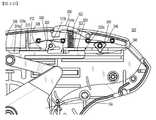
ここで図1~6を参照すると、本開示の実施形態に従う内視鏡的外科用クリップアプライヤが概して10と表されている。外科用クリップアプライヤ10は、概して、ハンドルアセンブリ100、及びハンドルアセンブリ100から遠位に延在する内視鏡アセンブリ200を含む。概して、内視鏡アセンブリ200は、ハブアセンブリ210、ハブアセンブリ210から延在するシャフトアセンブリ220、及びシャフトアセンブリ220の遠位端に枢動可能に接続された一対のジョー250を含む。任意に、少なくとも1つの使い捨て式外科用クリップカートリッジアセンブリ(図示せず)が、内視鏡アセンブリ200のシャフトアセンブリ220内に選択的に装填可能であり得る Here, with reference to FIGS. 1-6, the endoscopic surgical clip applier according to the embodiments of the present disclosure is generally represented as 10. The
ここで図1~2Bを参照すると、ハンドルアセンブリ100は、第1のまたは右側半部102a及び第2のまたは左側半部102bを有するハウジング102を含む。ハンドルアセンブリ100のハウジング102は、内視鏡アセンブリ200のハブアセンブリ210を支持するための鼻102c及び固定されたハンドル102dをさらに含むか、または画定する。 Referring here to FIGS. 1-2B, the
ハンドルアセンブリ100のハウジング102は、好適なポリマー、プラスチックまたは熱可塑性材料から形成されてもよい。ハンドルアセンブリ100のハウジング102がステンレス鋼等から作られてもよいことが、さらに企図される。 The
ハンドルアセンブリ100は、ハウジング102の右側半部102aと左側半部102bとの間で枢動可能に支持されているトリガ104を含む。トリガ104は、トリガ104及び固定されたハンドル102dが近づくように、第1の方向で枢動可能に可動であり、トリガ104及び固定されたハンドル102dが離れるように、第2の反対の方向に枢動可能に可動である。 The
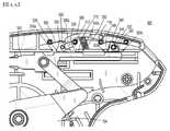
駆動バー106は、ハンドルアセンブリ100のハウジング102内に支持される。駆動バー106は、遠位端部106a及び近位端部106bを有する実質的に平坦な部材である。駆動バー106の遠位端部106aは、内視鏡的アセンブリ200の特徴と一致するように提供されるフック部材114を含む。駆動バー106は、トリガ104の作動時に、一対のジョー250を離間構成と接近構成との間で移動させるように、トリガ104、及び内視鏡的アセンブリ200の一対のジョー250に動作可能に連結される。具体的には、ハンドルアセンブリ100は、トリガ104及び駆動バー106に連結するように構成されたV字形リンク108を含む。V字形リンク108は、テール108aを有する第1の端部、及び間に間隔108dを画定するために相隔たる第2のアーム108b、108cを有する第2の端部を含む。V字形リンク108のテール108aは、トリガスロット104aを通ってトリガ104に海鮮可能に接続される。具体的には、V字形リンク108のテール108aは、トリガスロット104a内に画定されるピン(特に図示せず)を枢動可能に位置決めするように構成された開口108fを含む。第1と第2のアーム108b、108cとの間の間隔108dは、駆動バー106を受容するように構成される。V字形リンク108の第1及び第2のアーム108b、108c、及び駆動バー106は、V字形リンク108及び駆動バー106を枢動可能に接続するための駆動バーのピン110を位置付けるように構成された対応する開口部108e、106cを各々含む。V字形リンク108は、以下で詳述される通り、トリガ104の枢動動作を駆動バー106の長手方向の動作に変換させるように構成される。 The
駆動バー106は、装填する1つ以上の駆動構造を移動させ、完全に、または部分的にクリップ290(図6を参照されたい)を形成するために一対のジョー250を作動させ、その後、次のクリップ適用のために初期位置にリセットするように構成される。これを得るために、トリガ104が作動され、V字形リンク108が長手方向または遠位の様式で駆動バー106を前進させた後、次のクリップ適用のために、駆動バー106及びトリガ104をその元の位置に戻すために第1の復帰ばね112が提供されるように、付勢部材、例えば、第1の復帰ばね112が、遠位端部106aに隣接する駆動バー106を囲うように配置される。さらに、一実施形態において、トリガ104が作動された後、第2の復帰ばね113がトリガ104をその元の位置に戻すようにもたらされるように、第2の復帰ばね113は、ハンドルアセンブリ100のハウジング102内に配置され、トリガ104及び固定されたハンドル102dを動作可能に接続するように構成される。 The
引き続き図2A及び2Bを参照すると、外科用クリップアプライヤ10は、ハンドルアセンブリ100のハウジング102内に配置されたラチェットアセンブリ300を含む。ラチェットアセンブリ300は概して、第1のラック310、第2のラック320、第1の歯止め330、第2の歯止め340、及びハンドルアセンブリ100のハウジング102内に少なくとも部分的に支持された解除スイッチ350を含む。 Continuing with reference to FIGS. 2A and 2B, the
図2A及び2Bで示される通り、第1及び第2のラック310、320は、駆動バー106の上面106dによって支持されるか、またはその上に提供される。第1のラック310は、遠位端310a及び近位端310bを含む。第1のラック310は、その遠位端310aと近位端310bとの間で直列に複数の第1のラック歯312を画定する。同様に、第2のラック320は、遠位端320a及び近位端320bを含む第2のラック320は、その遠位端320aと近位端320bとの間で直列に複数の第2のラック歯322を画定する。 As shown in FIGS. 2A and 2B, the first and
駆動バー106の上面106dはまた、第1のラック310の遠位端310aに隣接して位置する遠位隙間またはウェル314a、及び第1のラック310の近位端310bと第2のラック320の遠位端320aとの間に位置する近位隙間またはウェル314bを含む。以下に詳述されるように、初期及び/またはリセット位置において、遠位ウェル314aは第1の歯止め330を受容するように構成され、近位ウェル314bは第2の歯止め340を受容するように構成される。 The
図2Bに示されるように、第1及び第2の歯止め330、340は、ハウジング102の右側半部102aと左側半部102bとの間でハンドルアセンブリ100内に枢動可能に取り付けられる。具体的には、第1の歯止め330は、ハウジング102の右側半部102aと左側半部102bとの間に、第1の歯止め330が第1のラック310と実質的に動作的に係合している場所で、第1の歯止めピン332によってハンドルアセンブリ100内に枢動可能に取り付けられる。第1の歯止めピン332は、第1の歯止め330内に画定されるスロット334を通って延在する。同様に、第2の歯止め340は、ハウジング102の右側半部102aと左側半部102bとの間に、第2の歯止め340が第2のラック320と実質的に係合している場所で、第2の歯止めピン342によってハンドルアセンブリ100内に枢動可能に取り付けられる。第2の歯止めピン342は、第2の歯止め340内に画定されるスロット344を通って延在する。 As shown in FIG. 2B, the first and
図2A及び2Bに示されるように、ラチェットアセンブリ300は、第1の歯止め330を第1のラック310と動作的に係合させるよう垂直に付勢するように構成された第1の歯止めばね336、及び第2の歯止め340を第2のラック320と動作的に係合させるよう垂直に付勢するように構成された第2の歯止めばね346をさらに含む。第1の歯止めばね336は、それぞれハウジング102の第1の組の支持ピン116a、116b上に掛止するように構成された遠位のフック336a及び近位のフック336bを含み、第2の歯止めばね346は、それぞれハウジング102の第2の組の支持ピン118a、118b上に掛止するように構成された遠位のフック346a及び近位のフック346bを含む。第1の及び第2の歯止めばね336、346は、第1の歯止め330の第1の歯止め歯338及び第2の歯止め340の第2の歯止め歯348を、それぞれ、複数の第1の及び第2のラック歯312、322と位置合わせまたは係合させて維持すると同時に、第1及び第2の歯止め330、340を回転したまたは傾いた位置に維持するように構成された方法で位置付けられていることが企図される。 As shown in FIGS. 2A and 2B, the
図2A及び2Bを引き続き参照して、ラチェットアセンブリ300は、ハンドルアセンブリ100のハウジング102内に少なくとも部分的に支持された解除スイッチ350をさらに含む。実施形態において、解除スイッチ350は、その近位端部分上に、解除スイッチ350がその周りを枢動可能であるようにハウジング102の取り付ピン119を位置決めするように構成されたスロット350aを含む。以下に詳述されるように、解除スイッチ350は、第1の歯止め330と動作可能に関連付けられ、その遠位端部分上に、第1の歯止め330を第1のラック310の複数の第1のラック歯312との動作的位置合わせまたは係合から外して選択的に移動させるよう、第1の歯止め330を係合するように動作可能である、係合部材350bを含む。他の実施形態において、解除スイッチ350は、その意図される目的に好適な種々の構成を含んでもよく、動作中に使用者にアクセスを提供するように構成された任意の人間工学的形状のものであってよい。 With reference to FIGS. 2A and 2B, the
実施形態において、第1の歯止め330は、そこから延在し、かつ、解除スイッチ350が第1の歯止め300の第1の歯止め歯338を第1のラック310の複数の第1のラック歯312との位置合わせまたは係合から外して移動させるのを防止するために、解除スイッチ350の係合部材350bに選択的に係合するように提供された、ロックアウト部材339を含む。 In an embodiment, the
ラチェットアセンブリ300は、ハンドルアセンブリ100のハウジング102内に支持され、解除スイッチ350を、解除スイッチ350が第1の歯止め330から係脱されるその非作動の定位置に戻すように、解除スイッチ350と動作可能に関連付けられた、解除ばね352をさらに含む。解除ばね352は、例えば、解除スイッチ350から延在する圧縮ばね、板ばね、または変形部材などの、任意の好適な付勢部材を含むことが企図される。 The
図3Aを簡単に参照すると、初期及び/またはリセット位置では、第1の歯止め330は、遠位ウェル314a内に配置され、第2の歯止め340は、近位ウェル314b内に配置される。 With brief reference to FIG. 3A, in the initial and / or reset position, the
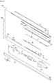
引き続き図3Aを参照し、さらに図3B~3Dを参照すると、ラチェットアセンブリ300の通常作動が開示される。使用時、トリガ104が作動されるにつれて、完全非作動位置から、第1及び第2のラック310、320の複数の第1及び第2のラック歯312、322は、それぞれ、第1及び第2の歯止め330、340の第1の歯止め歯338及び第2の歯止め歯348とそれぞれ位置合わせまたは係合するように、第1の位置に移動される(図3Bを参照されたい)。 Subsequent reference to FIGS. 3A and further with reference to FIGS. 3B-3D discloses normal operation of the
第1のラック310は、第1の長さ「L1」を有し(図3Aを参照されたい)、この第1の長さ「L1」は、トリガ104が完全駆動位置に到達すると、第1のラック310が一対のジョー250に対して遠位方向に移動するにつれて(図1を参照されたい)、第1の歯止め330が第1のラック310の上を逆転する(遠位ウェル314aから;図3Aを参照されたい)ことを可能にし、トリガ104が完全非作動位置に到達すると、第1のラック310が一対のジョー250に対して近位方向に移動するときに、第1の歯止め330が第1のラック310の上を前進して戻る(第1のラック310の近位端310bから;図3Dを参照されたい)ことを可能にする。第1のラック310の第1の長さ「L1」は、トリガ104、駆動バー106、またはハンドルアセンブリ100の完全ストローク長を画定し(図1を参照されたい)、この完全ストローク長において、クリップ290が完全に形成され、外科用クリップアプライヤ10から発射されている。 The
第2のラック320は、第1のラック310の第1の長さ「L1」未満である第2の長さ「L2」(図3Aを参照されたい)を有する。第2の長さ「L2」は、トリガ104が部分的作動位置に到達すると、第2のラック320が一対のジョー250に対して遠位方向に移動するにつれて(図1を参照されたい)、第2の歯止め340が第2のラック320の上を逆転する(近位ウェル314bから;図3Aを参照されたい)ことを可能にし、トリガ104が完全非作動位置に到達すると、第2のラック320が一対のジョー250に対して近位方向に移動するときに、第2の歯止め340が第2のラック320の上を前進して戻る(第2のラック320の近位端320bに近位である位置から;図3Dを参照されたい)ことを可能にする。第2のラック320の第2の長さ「L2」は、トリガ104、駆動バー106、またはハンドルアセンブリ100の部分ストローク長を画定し(図1を参照されたい)、この部分ストローク長において、クリップ290が部分的に形成されたか、または外科用クリップアプライヤ10から発射されるのに十分に形成され、新たなクリップ290が、一対のジャー250へのクリップ290の不注意な二重装填を伴わずに、一対のジャー250へ装填される。ラチェットアセンブリ300の通常作動において、第1及び第2の歯止め330、340ならびに各々の第1及び第2のラック310、320は、トリガ104、駆動バー106、またはハンドルアセンブリ100のストローク長が、完全に形成されたクリップ290が外科用クリップアプライヤ10から発射されることを達成するために、第1のラック310のより大きい第1の長さ「L1」によって決定されるように、協働することが企図される。 The
ここで図4A~4Cを参照すると、ラチェットアセンブリ300の部分的作動が開示される。ラチェットアセンブリ300の部分的作動は、胆管造影処置等を行うとき、使用者が、部分的に形成されたクリップ290を外科用クリップアプライヤ10から発射させることを可能にし得ることが企図される。また、ラチェットアセンブリ300の部分的作動は、クリップ290が不適切な位置に不注意に位置付けられるか、またはクリップ290が障害物上に位置付けられる場合に、使用者が、外科用クリップアプライヤ10からのクリップ290の発射を中断することを可能にし得ることが企図される。 Here, with reference to FIGS. 4A-4C, the partial operation of the
使用時、図4Aを参照して、第1及び第2のラック310、320の複数の第1及び第2のラック歯312、322が、それぞれ、第1及び第2の歯止め330、340の第1の歯止め歯338及び第2の歯止め歯348とそれぞれ位置合わせまたは係合するように、第1の位置に移動されるように、トリガ104が作動された後(図3Bを参照されたい)、解除スイッチ350は、解除スイッチ350がハウジング102の取り付ピン119の周りを枢動し、係合部材350bが第1の歯止め330を第1の歯止めピン332の周りで回転させるよう第1の歯止め330に係合するように、作動される。このような方法で、第1の歯止め330は、第2の位置へ移動され、第1のラック310の複数の第1のラック歯312との位置合わせまたは係合から外れる。図4Aに示される通り、解除スイッチ350は、第1の歯止め330を第2の位置に移動させるように作動されるが、図4Bに示される通り、第2の歯止め340は、第2の歯止め340が、第2のラック320を通過させるために第2のラック320の近位端320bの近位にある位置に移動されるまで、第1の位置に留まる。第1の歯止め330が第1のラック310との位置合わせまたは係合から外れた状態で、トリガ104、駆動バー106、またはハンドルアセンブリ100のストローク長が、第2のラック320のより少ない第2の長さ「L2」(第1のラック310の第1の長さ「L1」に対する)によって決定される。より少ない第2の長さ「L2」の間、第2の歯止め340と第2のラック320との間の係合は、ストロークの特定の部分の間、新たなクリップ290が、一対のジョー250へクリップ290の不注意な二重装填を伴わずに、一対のジョー250へ装填され得るように、一対のジョー250に装填されたクリップ290が、外科用クリップアプライヤ10から発射されるために十分に部分的に形成されるまで、トリガ104の不注意な復帰を防止する。 In use, with reference to FIG. 4A, the plurality of first and
ここで図4Cを参照すると、解除スイッチ350が第1の歯止め330を係合するように依然として作動されている状態で、第2の歯止め340が、ラチェットアセンブリ300の部分的作動を完了するように、第2のラック320上に前進して戻り、近位ウェル314b内に配置されると、トリガ104は、完全非作動位置に(その部分的作動位置から)戻され得る。解除スイッチ350は次いで、解除ばね352の付勢の下で解除スイッチ350がその元の位置に戻り、第1の歯止め330が遠位ウェル314a内に配置されるように、解除され得る(図3Aを参照されたい)。 Referring now to FIG. 4C, the
実施形態において、解除スイッチ350がラチェットアセンブリ300の部分作動の一部の間に解除され(例えば、図4Aを参照されたい)、それにより、解除スイッチ350の係合部材350bが第1の歯止め330から係脱される場合、第1の歯止めばね336は、第1の歯止め330を第1の位置に戻すように提供され、それにより、第1のラック310の複数の第1のラック歯312が、第1の歯止め330の第1の歯止め歯338と位置合わせまたは係合するように移動されることが企図される。したがって、外科用クリップアプライヤ10は、ラチェットアセンブリ300(図3A~3Dを参照されたい)の通常作動に戻り、そこにおいて、トリガ104、駆動バー106またはハンドルアセンブリ100のストローク長は、完全に形成されたクリップ290が外科用クリップアプライヤ10から発射されることを達成するために、第1のラック310のより大きい第1の長さ「L1」(第2のラック320の第2の長さ「L2」と比べて)によって決定される。この特長は、例えば、解除スイッチ350が不注意に作動されるなどの事例において、有利であり得る。 In an embodiment, the
ここで図5A~5Cを参照すると、ラチェットアセンブリ300の通常作動の戻りストロークが開示される。第1の歯止め330が第1のラック310の近位端310bに配置され、第2の歯止め340が第2のラック320の近位端320bに近位の位置に配置されるように(図5Aを参照されたい)、トリガ104が完全に作動された位置にある状態で、トリガ104は、第1の及び第2のラック310、320が一対のジョー250に対して近位の方向に移動されるように解除される。それと同時に、第1及び第2の歯止め330、340は、それぞれ、第1の及び第2のラック310、320の上を前進され、それにより、第1及び第2のラック310、320の複数の第1及び第2のラック歯312、322が、それぞれ、第1及び第2の歯止め330、340の第1の歯止め歯338及び第2の歯止め歯348とそれぞれ位置合わせまたは係合されるように、第1の位置に移動される(図5Bを参照されたい)。戻りストロークの間、第1の歯止め330は、解除スイッチ350が作動される場合に第1の歯止め330のロックアウト部材339が解除スイッチ350の係合部材350bに係合するように位置付けられるように、第1の歯止めピン332の周りで回転させられる。この方法で、第1の歯止め330の第1の歯止め歯338と第1のラック310の複数の第1のラック歯312との間の位置合わせまたは係合は、解除スイッチ350が、第1の歯止め300の第1の歯止め歯338を第1のラック310の複数の第1のラック歯312との位置合わせまたは係合から外して回転または移動させるよう第1の歯止め330に係合するのを防止するために、第1の歯止め330のロックアウト部材339と協働する。かかる特長は、トリガ104が完全に非作動の位置に移動され、新たなクリップ290が一対のジョー250に装填され、ラチェットアセンブリ300が初期及び/またはリセット位置に移動されることを確実にし、その位置において、第1の歯止め330が遠位ウェル314a内に配置され、第2の歯止め340が近位ウェル314b内に配置される(図3Aを参照されたい)ことが企図される。 Here, with reference to FIGS. 5A-5C, the return stroke of the
本開示の図は、第1の及び第2のラック310、320が駆動バー106上で長手方向に整列され、解除スイッチ350が第1の歯止め330と選択的に係合可能である構成を例示するが、第1の及び第2のラック310、320は、第1の及び第2のラック310、320が逆になっている、積み重ねられている、横並びである、またはそれらの組み合わせである構成を含み得ることが企図される。さらに、解除スイッチ350が第2の歯止め340と選択的に係合可能であり得ることが企図される。それに加えて、解除スイッチ350を作動することで、可聴式及び/または触覚フィードバックが使用者に発せられ得ることが企図される。 The figure of the present disclosure illustrates a configuration in which the first and
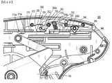
上で述べられ、図6に例示されるように、外科用クリップアプライヤ10は、ハブアセンブリ210、シャフトアセンブリ220、及び一対のジョー250を含む内視鏡アセンブリ200を含む。ハブアセンブリ210は、ハンドルアセンブリ100のハウジング102の鼻102c(図2Aを参照されたい)上に回転可能に取り付けられ、シャフトアセンブリ220及びその上の一対のジョー250の、シャフトアセンブリ220の長手方向重心軸に対する360度回転を可能にするように、シャフトアセンブリ220の近位端部分に接続される。ハブアセンブリ210は、単に臨床医の指を用いて回転させられるように、好適な構成を有する。 As mentioned above and illustrated in FIG. 6, the
内視鏡アセンブリ200は、トリガ104の作動時に一対のジョー250を離間構成と接近構成との間で移動させるために駆動バー106を駆動機構400に動作可能に接続するためのスピンドルリンク260を含む。具体的には、駆動バー106のフック部材114(図2Bを参照されたい)は、スピンドルリンク260の第1の端部260aに連結され、駆動機構400のスピンドル270は、スピンドルリンク260の第2の端部260bに連結されている。この方法で、駆動バー106の遠位方向及び近位方向への平行移動がそれによって、スピンドル270をそれぞれ前進及び後退させ得る。 The
駆動機構400は、示されるいくつかの外科用クリップ290を整列された様式でクリップチャネル部材280の上に保持するための、細長いクリップチャネル部材280をさらに含む。細長いクリップチャネル部材280を通して外科用クリップ290を遠位に促すように、クリップフォロワ282及びクリップフォロワばね284が提供される。細長いクリップチャネル部材280の上に重なり、クリップフォロワ282及びクリップフォロワばね284及び外科用クリップ290を細長いクリップチャネル部材280内に保持し、それらを細長いクリップチャネル部材280内で遠位に導くように、チャネルカバー286が提供される。 The
駆動機構400はまた、外科用クリップ290を一対のジョー250間に供給するための供給バー410も有する。駆動機構400はまた、フィラー構成要素420及びウェッジプレート430も含む。 The
内視鏡アセンブリ200の構築及び動作のより詳細な説明については、米国特許第7,637,917号を参照してもよく、その全内容は参照により本明細書に組み込まれる。 A more detailed description of the construction and operation of the
前述の説明は、本開示の単なる例示であることを理解されたい。様々な代替手段及び手段が本開示から逸脱することなく当業者によって考案され得る。したがって、本開示は、そのようなすべての代替手段、修正及び差異を包含することが意図される。添付の図面を参照して説明される実施形態は、本開示のある特定の実施例を示すためだけに表される。上記及び/または添付の特許請求で説明されるものと非本質的に異なる他の要素、行程、方法及び技術も、本開示の範囲内であることが意図される。
It should be understood that the above description is merely an example of the present disclosure. Various alternatives and means may be devised by one of ordinary skill in the art without departing from this disclosure. Accordingly, this disclosure is intended to include all such alternatives, modifications and differences. The embodiments described with reference to the accompanying drawings are presented solely to illustrate certain embodiments of the present disclosure. Other elements, processes, methods and techniques that are non-essentially different from those described in the above and / or the accompanying claims are also intended to be within the scope of this disclosure.
Claims (14)
Translated fromJapanese内視鏡アセンブリであって、
シャフトアセンブリ及び
前記シャフトアセンブリに連結され、前記シャフトアセンブリから延在する一対のジョー部材
を含む、内視鏡アセンブリと、
ハンドルアセンブリであって、
前記内視鏡アセンブリに選択的に接続可能なハウジング、
前記ハウジングから延在する固定されたハンドル、
前記固定されたハンドルに枢動可能に接続されたトリガ、
前記ハンドルアセンブリの前記ハウジング内に配置され、前記トリガの作動時に、離間構成と接近構成との間で前記一対のジョー部材を移動させるように、前記トリガ及び前記一対のジョー部材に連結された駆動バー、
前記ハンドルアセンブリの前記ハウジング内に配置されたラチェットアセンブリであって、
前記駆動バーに連結された第1のラックであって、複数の第1のラック歯を画定し、かつ遠位端及び近位端を有し、前記第1のラックの前記遠位端と前記近位端との間の第1の長さを含む、第1のラックと、
前記駆動バーに連結された第2のラックであって、前記第2のラックは、前記第1のラックから離間され、複数の第2のラック歯を画定し、かつ遠位端及び近位端を有し、前記第2のラックの前記遠位端と前記近位端との間の第2の長さを含み、前記第2のラックの前記第2の長さは、前記第1のラックの前記第1の長さよりも短い、第2のラックと、
前記ハンドルアセンブリの前記ハウジング内に取り付けられた第1の歯止めと、
前記ハンドルアセンブリの前記ハウジング内に取り付けられた第2の歯止めと、
前記ハンドルアセンブリの前記ハウジング内に少なくとも部分的に支持された解除スイッチと
を含む、ラチェットアセンブリ
を含む、ハンドルアセンブリと
を備え、前記第1のラックの前記近位端と前記第2のラックの前記遠位端との間の近位ウェルは、前記第1の歯止めのための隙間を画定し、
前記第2のラックの前記近位端を近位方向に越えた空間は、前記第2の歯止めのための隙間を画定し、
前記トリガの作動時に、前記第1の歯止め及び前記第2の歯止めが前記第1の歯止め及び前記第2の歯止めのためのそれぞれの隙間内に配置されるまで、前記トリガの移動の方向の解除及び逆転を妨げるように、前記第1の歯止め、前記第2の歯止めはそれぞれ、前記第1のラックの前記複数の第1のラック歯、前記第2のラックの前記複数の第2のラック歯と位置合わせまたは係合するように構成され、
前記解除スイッチは、前記第2の歯止めが前記第2の歯止めのための前記隙間内に配置された後、前記トリガの前記移動の方向が早く逆転され得るように、前記第1の歯止めを移動させて、前記第1のラックの前記複数の第1のラック歯との位置合わせまたは係合から外すように選択的に作動可能である、内視鏡的外科用クリップアプライヤ。An endoscopic surgical clip applier,
It ’s an endoscope assembly.
An endoscope assembly that includes a shaft assembly and a pair of jaw members thatare connected to and extend from the shaft assembly.
It's a handle assembly
A housing that can be selectively connected to the endoscope assembly,
A fixed handle extending from the housing,
A trigger, pivotally connected to the fixed handle,
A drive that is located in the housing of the handle assembly andis coupled to the trigger and the pair of jaw members so as to move the pair of jaw members between the separated and close configurations when the trigger is activated. bar,
A ratchet assembly disposed within the housing of the handle assembly.
A first rack coupled to the drive bar, defining a plurality of first rack teeth and having a distal end and a proximal end, the distal end of the first rack and the said. A first rack, including a first length between the proximal end, and
A second rack coupled to the drive bar, wherein the second rack is separated from the first rack, defines a plurality of second rack teeth, and has distal and proximal ends. The second length of the second rack includes the second length between the distal end and the proximal end of the second rack. A second rack, which is shorter than the first lengthof the
A first pawl mounted within the housing of the handle assembly,
A second pawl mounted within the housing of the handle assembly,
With a release switch that is at least partially supported within the housing of the handle assembly
Including ratchet assembly
Including handle assembly and
The proximal well between the proximal end of the first rack and the distal end of the second rack defines a gap for the first pawl.
A space proximally beyond the proximal end of the second rack defines a gap for the second pawl.
When the trigger is activated, the direction of movement of the trigger is released until the first pawl and the second pawl are placed in the respective gaps for the first pawl and the second pawl. And so as to prevent reversal, the first pawl and the second pawl are the plurality of first rack teeth of the first rack and the plurality of second rack teeth of the second rack, respectively. Configured to align or engage with
The release switch moves the first stop so that after the second stop is placed in the gap for the second stop, the direction of movement of the trigger can be quickly reversed. An endoscopic surgical clip applierthat can be selectively actuated to displace or disengage the first rack from its plurality of first rack teeth .
内視鏡アセンブリであって、
シャフトアセンブリ及び
前記シャフトアセンブリに連結され、前記シャフトアセンブリから延在する一対のジョー部材
を含む、内視鏡アセンブリと、
ハンドルアセンブリであって、
前記内視鏡アセンブリに選択的に接続可能なハウジング、
前記ハウジングから延在する固定されたハンドル、
前記固定されたハンドルに枢動可能に接続されたトリガ、
前記ハンドルアセンブリの前記ハウジング内に配置され、前記トリガの作動時に、離間構成と接近構成との間で前記一対のジョー部材を移動させるように、前記トリガ及び前記一対のジョー部材に連結された駆動バー、
前記ハンドルアセンブリの前記ハウジング内に配置されたラチェットアセンブリであって、
前記駆動バーの上部分で画定された第1のラックであって、前記第1のラックは、複数の第1のラック歯を含み、遠位端及び近位端を有し、前記第1のラックは、その前記遠位端と前記近位端との間の第1の長さを含む、第1のラック、
前記駆動バーの前記上部分で画定された第2のラックであって、前記第2のラックは、複数の第2のラック歯を含み、遠位端及び近位端を有し、前記第2のラックは、その前記遠位端と前記近位端との間の第2の長さを含み、前記第2のラックの前記第2の長さは、前記第1のラックの前記第1の長さよりも短い、第2のラック、
前記ハンドルアセンブリ内に移動可能に取り付けられ、前記第1のラックの前記複数の第1のラック歯と選択的に係合可能な第1の歯止め、
前記ハンドルアセンブリ内に移動可能に取り付けられ、前記第2のラックの前記複数の第2のラック歯と選択的に係合可能な第2の歯止め、
前記ハンドルアセンブリの前記ハウジング内に少なくとも部分的に支持された解除スイッチ
を含む、ラチェットアセンブリ
を含む、ハンドルアセンブリと
を備え、前記第1のラックの前記近位端と前記第2のラックの前記遠位端との間の近位ウェルは、前記第1の歯止めのための隙間を画定し、
前記第2のラックの前記近位端を近位方向に越えた空間は、前記第2の歯止めのための隙間を画定し、
前記トリガの作動時に、前記第1の歯止め及び前記第2の歯止めが前記第1の歯止め及び前記第2の歯止めのためのそれぞれの隙間内に配置されるまで、前記トリガの移動の方向の解除及び逆転を妨げるように、前記第1の歯止め、前記第2の歯止めはそれぞれ、前記第1のラックの前記複数の第1のラック歯、前記第2のラックの前記複数の第2のラック歯と位置合わせまたは係合するように構成され、
前記解除スイッチは、前記第2の歯止めが前記第2の歯止めのための前記隙間内に配置された後、前記トリガの前記移動の方向が早く逆転され得るように、前記第1の歯止めを移動させて、前記第1のラックの前記複数の第1のラック歯との位置合わせまたは係合から外すように選択的に作動可能である、内視鏡的外科用クリップアプライヤ。An endoscopic surgical clip applier,
It ’s an endoscope assembly.
An endoscope assembly that includes a shaft assembly and a pair of jaw members thatare connected to and extend from the shaft assembly.
It's a handle assembly
A housing that can be selectively connected to the endoscope assembly,
A fixed handle extending from the housing,
A trigger, pivotally connected to the fixed handle,
A drive that is located in the housing of the handle assembly andis coupled to the trigger and the pair of jaw members so as to move the pair of jaw members between the separated and close configurations when the trigger is activated. bar,
A ratchet assembly disposed within the housing of the handle assembly.
A first rack defined by an upper portion of the drive bar,the first rack comprising a plurality of first rack teeth, having a distal end and a proximal end, said first. The rack comprises a first length between said distal end and said proximal end, the first rack,
A second rack defined by the upper portion of the drive bar,the second rack comprising a plurality of second rack teeth, having a distal end and a proximal end, said second. The rack includes a second length between its distal end and its proximal end, the second length of the second rack being the first length of the first rack. Second rack,shorter than the length ,
A first pawl, movably mounted within the handle assembly and selectively engageable with the plurality of first rack teeth of the first rack.
A second pawl, movably mountedwithin the handle assembly and selectively engageable with the plurality of second rack teeth of the second rack.
A release switch that is at least partially supported within the housing of the handle assembly.
Including ratchet assembly
Including handle assembly and
The proximal well between the proximal end of the first rack and the distal end of the second rack defines a gap for the first pawl.
A space proximally beyond the proximal end of the second rack defines a gap for the second pawl.
When the trigger is activated, the direction of movement of the trigger is released until the first pawl and the second pawl are placed in the respective gaps for the first pawl and the second pawl. And so as to prevent reversal, the first pawl and the second pawl are the plurality of first rack teeth of the first rack and the plurality of second rack teeth of the second rack, respectively. Configured to align or engage with
The release switch moves the first stop so that after the second stop is placed in the gap for the second stop, the direction of movement of the trigger can be quickly reversed. An endoscopic surgical clip applierthat can be selectively actuated to displace or disengage the first rack from its plurality of first rack teeth .
Applications Claiming Priority (4)
| Application Number | Priority Date | Filing Date | Title |
|---|---|---|---|
| US201762455090P | 2017-02-06 | 2017-02-06 | |
| US62/455,090 | 2017-02-06 | ||
| US15/865,843US10758244B2 (en) | 2017-02-06 | 2018-01-09 | Endoscopic surgical clip applier |
| US15/865,843 | 2018-01-09 |
Publications (2)
| Publication Number | Publication Date |
|---|---|
| JP2018126504A JP2018126504A (en) | 2018-08-16 |
| JP7086619B2true JP7086619B2 (en) | 2022-06-20 |
Family
ID=61163597
Family Applications (1)
| Application Number | Title | Priority Date | Filing Date |
|---|---|---|---|
| JP2018013576AActiveJP7086619B2 (en) | 2017-02-06 | 2018-01-30 | Endoscopic surgical clip applier |
Country Status (4)
| Country | Link |
|---|---|
| US (1) | US10758244B2 (en) |
| EP (1) | EP3357436B1 (en) |
| JP (1) | JP7086619B2 (en) |
| CN (1) | CN108392242A (en) |
Families Citing this family (74)
| Publication number | Priority date | Publication date | Assignee | Title |
|---|---|---|---|---|
| CA2809110A1 (en) | 2004-10-08 | 2006-04-20 | Tyco Healthcare Group Lp | Apparatus for applying surgical clips |
| EP2157920B1 (en) | 2007-03-26 | 2017-09-27 | Covidien LP | Endoscopic surgical clip applier |
| US8465502B2 (en) | 2008-08-25 | 2013-06-18 | Covidien Lp | Surgical clip applier and method of assembly |
| US9358015B2 (en) | 2008-08-29 | 2016-06-07 | Covidien Lp | Endoscopic surgical clip applier with wedge plate |
| US9186136B2 (en) | 2009-12-09 | 2015-11-17 | Covidien Lp | Surgical clip applier |
| US8545486B2 (en) | 2009-12-15 | 2013-10-01 | Covidien Lp | Surgical clip applier |
| US8403945B2 (en) | 2010-02-25 | 2013-03-26 | Covidien Lp | Articulating endoscopic surgical clip applier |
| US8968337B2 (en) | 2010-07-28 | 2015-03-03 | Covidien Lp | Articulating clip applier |
| US20130131697A1 (en) | 2011-11-21 | 2013-05-23 | Covidien Lp | Surgical clip applier |
| US9364216B2 (en) | 2011-12-29 | 2016-06-14 | Covidien Lp | Surgical clip applier with integrated clip counter |
| US9532787B2 (en) | 2012-05-31 | 2017-01-03 | Covidien Lp | Endoscopic clip applier |
| US9113892B2 (en) | 2013-01-08 | 2015-08-25 | Covidien Lp | Surgical clip applier |
| US9750500B2 (en) | 2013-01-18 | 2017-09-05 | Covidien Lp | Surgical clip applier |
| US9775624B2 (en) | 2013-08-27 | 2017-10-03 | Covidien Lp | Surgical clip applier |
| US9931124B2 (en) | 2015-01-07 | 2018-04-03 | Covidien Lp | Reposable clip applier |
| CN107205747B (en) | 2015-01-15 | 2020-09-08 | 柯惠有限合伙公司 | Reusable endoscopic surgical clip applier |
| US10159491B2 (en) | 2015-03-10 | 2018-12-25 | Covidien Lp | Endoscopic reposable surgical clip applier |
| US10660652B2 (en) | 2015-10-10 | 2020-05-26 | Covidien Lp | Endoscopic surgical clip applier |
| CN108348259B (en) | 2015-11-03 | 2020-12-11 | 柯惠有限合伙公司 | Endoscopic Surgical Fixture Applicator |
| US10702280B2 (en) | 2015-11-10 | 2020-07-07 | Covidien Lp | Endoscopic reposable surgical clip applier |
| US10905425B2 (en) | 2015-11-10 | 2021-02-02 | Covidien Lp | Endoscopic reposable surgical clip applier |
| CN108472044B (en) | 2016-01-11 | 2021-04-16 | 柯惠有限合伙公司 | endoscope-reserved surgical clip applier |
| AU2016388454A1 (en) | 2016-01-18 | 2018-07-19 | Covidien Lp | Endoscopic surgical clip applier |
| CA2958160A1 (en) | 2016-02-24 | 2017-08-24 | Covidien Lp | Endoscopic reposable surgical clip applier |
| WO2018027788A1 (en) | 2016-08-11 | 2018-02-15 | Covidien Lp | Endoscopic surgical clip applier and clip applying systems |
| CN109640844B (en) | 2016-08-25 | 2021-08-06 | 柯惠Lp公司 | Endoscopic Surgical Clip Appliers and Applicator Systems |
| US10639044B2 (en) | 2016-10-31 | 2020-05-05 | Covidien Lp | Ligation clip module and clip applier |
| US10660651B2 (en) | 2016-10-31 | 2020-05-26 | Covidien Lp | Endoscopic reposable surgical clip applier |
| US10610236B2 (en) | 2016-11-01 | 2020-04-07 | Covidien Lp | Endoscopic reposable surgical clip applier |
| US10492795B2 (en) | 2016-11-01 | 2019-12-03 | Covidien Lp | Endoscopic surgical clip applier |
| US10426489B2 (en) | 2016-11-01 | 2019-10-01 | Covidien Lp | Endoscopic reposable surgical clip applier |
| US10709455B2 (en) | 2017-02-02 | 2020-07-14 | Covidien Lp | Endoscopic surgical clip applier |
| US11116514B2 (en) | 2017-02-06 | 2021-09-14 | Covidien Lp | Surgical clip applier with user feedback feature |
| US10758244B2 (en) | 2017-02-06 | 2020-09-01 | Covidien Lp | Endoscopic surgical clip applier |
| US10660725B2 (en) | 2017-02-14 | 2020-05-26 | Covidien Lp | Endoscopic surgical clip applier including counter assembly |
| US10603038B2 (en) | 2017-02-22 | 2020-03-31 | Covidien Lp | Surgical clip applier including inserts for jaw assembly |
| US10548602B2 (en) | 2017-02-23 | 2020-02-04 | Covidien Lp | Endoscopic surgical clip applier |
| US11583291B2 (en) | 2017-02-23 | 2023-02-21 | Covidien Lp | Endoscopic surgical clip applier |
| US10675043B2 (en) | 2017-05-04 | 2020-06-09 | Covidien Lp | Reposable multi-fire surgical clip applier |
| US10722235B2 (en) | 2017-05-11 | 2020-07-28 | Covidien Lp | Spring-release surgical clip |
| US10660723B2 (en) | 2017-06-30 | 2020-05-26 | Covidien Lp | Endoscopic reposable surgical clip applier |
| US10639032B2 (en) | 2017-06-30 | 2020-05-05 | Covidien Lp | Endoscopic surgical clip applier including counter assembly |
| US10675112B2 (en) | 2017-08-07 | 2020-06-09 | Covidien Lp | Endoscopic surgical clip applier including counter assembly |
| US10863992B2 (en) | 2017-08-08 | 2020-12-15 | Covidien Lp | Endoscopic surgical clip applier |
| US10932790B2 (en) | 2017-08-08 | 2021-03-02 | Covidien Lp | Geared actuation mechanism and surgical clip applier including the same |
| US10786262B2 (en) | 2017-08-09 | 2020-09-29 | Covidien Lp | Endoscopic reposable surgical clip applier |
| US10786263B2 (en) | 2017-08-15 | 2020-09-29 | Covidien Lp | Endoscopic reposable surgical clip applier |
| US10835341B2 (en) | 2017-09-12 | 2020-11-17 | Covidien Lp | Endoscopic surgical clip applier and handle assemblies for use therewith |
| US10835260B2 (en) | 2017-09-13 | 2020-11-17 | Covidien Lp | Endoscopic surgical clip applier and handle assemblies for use therewith |
| US10758245B2 (en) | 2017-09-13 | 2020-09-01 | Covidien Lp | Clip counting mechanism for surgical clip applier |
| US10653429B2 (en) | 2017-09-13 | 2020-05-19 | Covidien Lp | Endoscopic surgical clip applier |
| US10828036B2 (en) | 2017-11-03 | 2020-11-10 | Covidien Lp | Endoscopic surgical clip applier and handle assemblies for use therewith |
| US10932791B2 (en) | 2017-11-03 | 2021-03-02 | Covidien Lp | Reposable multi-fire surgical clip applier |
| US11376015B2 (en) | 2017-11-03 | 2022-07-05 | Covidien Lp | Endoscopic surgical clip applier and handle assemblies for use therewith |
| US11116513B2 (en) | 2017-11-03 | 2021-09-14 | Covidien Lp | Modular surgical clip cartridge |
| US10945734B2 (en) | 2017-11-03 | 2021-03-16 | Covidien Lp | Rotation knob assemblies and surgical instruments including the same |
| US10722236B2 (en) | 2017-12-12 | 2020-07-28 | Covidien Lp | Endoscopic reposable surgical clip applier |
| US10743887B2 (en) | 2017-12-13 | 2020-08-18 | Covidien Lp | Reposable multi-fire surgical clip applier |
| US10959737B2 (en) | 2017-12-13 | 2021-03-30 | Covidien Lp | Reposable multi-fire surgical clip applier |
| US10849630B2 (en) | 2017-12-13 | 2020-12-01 | Covidien Lp | Reposable multi-fire surgical clip applier |
| US11051827B2 (en) | 2018-01-16 | 2021-07-06 | Covidien Lp | Endoscopic surgical instrument and handle assemblies for use therewith |
| US10993721B2 (en) | 2018-04-25 | 2021-05-04 | Covidien Lp | Surgical clip applier |
| US10786273B2 (en) | 2018-07-13 | 2020-09-29 | Covidien Lp | Rotation knob assemblies for handle assemblies |
| US11246601B2 (en) | 2018-08-13 | 2022-02-15 | Covidien Lp | Elongated assemblies for surgical clip appliers and surgical clip appliers incorporating the same |
| US11278267B2 (en) | 2018-08-13 | 2022-03-22 | Covidien Lp | Latch assemblies and surgical instruments including the same |
| US11219463B2 (en) | 2018-08-13 | 2022-01-11 | Covidien Lp | Bilateral spring for surgical instruments and surgical instruments including the same |
| US11051828B2 (en) | 2018-08-13 | 2021-07-06 | Covidien Lp | Rotation knob assemblies and surgical instruments including same |
| US11344316B2 (en) | 2018-08-13 | 2022-05-31 | Covidien Lp | Elongated assemblies for surgical clip appliers and surgical clip appliers incorporating the same |
| US11147566B2 (en) | 2018-10-01 | 2021-10-19 | Covidien Lp | Endoscopic surgical clip applier |
| US11524398B2 (en) | 2019-03-19 | 2022-12-13 | Covidien Lp | Gear drive mechanisms for surgical instruments |
| US11779340B2 (en) | 2020-01-02 | 2023-10-10 | Covidien Lp | Ligation clip loading device |
| US11723669B2 (en) | 2020-01-08 | 2023-08-15 | Covidien Lp | Clip applier with clip cartridge interface |
| US12114866B2 (en) | 2020-03-26 | 2024-10-15 | Covidien Lp | Interoperative clip loading device |
| US12419648B2 (en) | 2022-09-26 | 2025-09-23 | Covidien Lp | Two-part fasteners for surgical clip appliers and surgical clip appliers for deploying the same |
Citations (4)
| Publication number | Priority date | Publication date | Assignee | Title |
|---|---|---|---|---|
| US20060085015A1 (en) | 2004-10-08 | 2006-04-20 | Whitfield Kenneth H | Endoscopic surgical clip applier |
| JP2015096202A (en) | 2008-08-29 | 2015-05-21 | コヴィディエン リミテッド パートナーシップ | Endoscopic surgical clip applier with connector plate |
| US20160242784A1 (en) | 2008-08-29 | 2016-08-25 | Covidien Lp | Endoscopic surgical clip applier |
| WO2016192096A1 (en) | 2015-06-05 | 2016-12-08 | Covidien Lp | Endoscopic reposable surgical clip applier |
Family Cites Families (692)
| Publication number | Priority date | Publication date | Assignee | Title |
|---|---|---|---|---|
| US3120230A (en) | 1960-10-24 | 1964-02-04 | Jack H Sanders | Surgical clamp |
| US3363628A (en) | 1964-09-28 | 1968-01-16 | Peter B Samuels | Hemostatic clip |
| US3735762A (en) | 1970-04-27 | 1973-05-29 | Us Corp Baltimo E | Instrument for ligating suturing and dividing organic tubular structures |
| US3675688A (en) | 1970-04-27 | 1972-07-11 | United States Surgical Corp | Instrument for ligating, suturing and dividing organic tubular structures |
| US3638847A (en) | 1970-07-06 | 1972-02-01 | United States Surgical Corp | Ratchet-driven cartridge for surgical instruments |
| US3867944A (en) | 1972-10-27 | 1975-02-25 | Wood Ernest C | Hemostatic clip and applicator therefor |
| US4412539A (en) | 1976-10-08 | 1983-11-01 | United States Surgical Corporation | Repeating hemostatic clip applying instruments and multi-clip cartridges therefor |
| US4611595A (en) | 1977-08-05 | 1986-09-16 | Charles H. Klieman | Spring activated hemostatic clip applicator |
| CA1124605A (en) | 1977-08-05 | 1982-06-01 | Charles H. Klieman | Surgical stapler |
| CA1134701A (en) | 1977-10-17 | 1982-11-02 | David T. Green | Surgical clip applicator |
| US4242902A (en) | 1978-05-11 | 1981-01-06 | United States Surgical Corporation | Surgical clip applicator |
| US4418694A (en) | 1979-06-18 | 1983-12-06 | Ethicon, Inc. | Non-metallic, bio-compatible hemostatic clips |
| US4662374A (en) | 1979-08-02 | 1987-05-05 | American Hospital Supply Corp. | Ligator device |
| US4296751A (en) | 1979-08-02 | 1981-10-27 | Blake Joseph W Iii | Surgical device |
| US4372316A (en) | 1979-08-02 | 1983-02-08 | Blake Joseph W Iii | Surgical device |
| US4532925A (en) | 1979-08-02 | 1985-08-06 | Joseph W. Blake, III | Ligator device |
| US4480640A (en) | 1980-04-22 | 1984-11-06 | Senco Products, Inc. | Ligating device |
| US4408603A (en) | 1980-10-24 | 1983-10-11 | Blake Joseph W Iii | Surgical device |
| US4500024A (en) | 1980-11-19 | 1985-02-19 | Ethicon, Inc. | Multiple clip applier |
| CA1163889A (en) | 1981-02-02 | 1984-03-20 | Allegiance Corporation | Surgical device |
| US4522207A (en) | 1981-02-06 | 1985-06-11 | Charles H. Klieman | Spring activated hemostatic clip applicator |
| US4646740A (en) | 1981-02-23 | 1987-03-03 | Edward Weck & Co., Inc. | Automatic hemoclip applier |
| US4576166A (en) | 1981-06-29 | 1986-03-18 | American Cyanamid Company | Surgical ligating instrument |
| US4662373A (en) | 1981-06-29 | 1987-05-05 | American Cyanamid Company | Surgical ligating instrument |
| US4498476A (en) | 1981-08-27 | 1985-02-12 | Ethicon, Inc. | Non-metallic, bio-compatible hemostatic clips with interlocking latch means |
| US4487204A (en) | 1981-10-14 | 1984-12-11 | Nomel | Device for applying haemostatic clips |
| US4491133A (en) | 1982-02-05 | 1985-01-01 | Ethicon, Inc. | Folding cartridge for a multiple clip applier |
| US4471780A (en) | 1982-02-05 | 1984-09-18 | Ethicon, Inc. | Multiple ligating clip applier instrument |
| US4480641A (en) | 1982-02-05 | 1984-11-06 | Ethicon, Inc. | Tip configuration for a ligating clip applier |
| US4509518A (en) | 1982-02-17 | 1985-04-09 | United States Surgical Corporation | Apparatus for applying surgical clips |
| US4487205A (en) | 1982-04-26 | 1984-12-11 | Ethicon, Inc. | Non-metallic, bio-compatible hemostatic clips |
| US4545377A (en) | 1982-09-24 | 1985-10-08 | Ethicon, Inc. | Non-metallic, bio-compatible hemostatic clips (two piece configured to lock tighter the larger the vessel being closed) |
| US4512345A (en) | 1982-09-30 | 1985-04-23 | United States Surgical Corporation | Surgical clip applying apparatus, and clips and clip train for use therein |
| US4492232A (en) | 1982-09-30 | 1985-01-08 | United States Surgical Corporation | Surgical clip applying apparatus having fixed jaws |
| US4815466A (en) | 1982-09-30 | 1989-03-28 | Perlin Alfred R | Surgical clip |
| US4674504A (en) | 1982-10-06 | 1987-06-23 | Klieman Charles H | Spring activated hemostatic clip applicator |
| US4534351A (en) | 1982-10-20 | 1985-08-13 | Senmed, Inc. | Ligator |
| US4796625A (en) | 1982-11-15 | 1989-01-10 | Codman & Shurtleff, Inc. | Aneurysm clip |
| US4562839A (en) | 1983-01-06 | 1986-01-07 | Blake Joseph W Iii | Surgical instrument |
| US4556058A (en) | 1983-08-17 | 1985-12-03 | United States Surgical Corporation | Apparatus for ligation and division with fixed jaws |
| US4602631A (en) | 1983-09-08 | 1986-07-29 | Noboru Funatsu | Forceps for clamping surgical clips |
| US4637395A (en) | 1983-10-04 | 1987-01-20 | Aesculap-Werke Ag | Applicator for C-shaped scalp clips |
| DE3335985C2 (en) | 1983-10-04 | 1986-12-04 | Aesculap-Werke Ag Vormals Jetter & Scheerer, 7200 Tuttlingen | Magazine for holding C-shaped scalp clips |
| US4549544A (en) | 1983-10-31 | 1985-10-29 | Senmed, Inc. | Clip stop for a surgical ligating instrument |
| US4576165A (en) | 1984-01-23 | 1986-03-18 | United States Surgical Corporation | Surgical ligation and cutting device with safety means |
| US4557263A (en) | 1984-01-23 | 1985-12-10 | United States Surgical Corporation | Apparatus for applying surgical clips |
| US4616650A (en) | 1984-07-27 | 1986-10-14 | United States Surgical Corporation | Apparatus for applying surgical clips |
| US4598711A (en) | 1984-08-09 | 1986-07-08 | American Cyanamid Company | Surgical instrument |
| US4590937A (en) | 1985-01-07 | 1986-05-27 | American Cyanamid Company | Nonmetallic surgical clip |
| US5127915A (en) | 1984-10-29 | 1992-07-07 | Mattson Philip D | Surgical instrument for severing and clamping an umbilical cord |
| US4572183A (en) | 1984-11-26 | 1986-02-25 | Senmed, Inc. | Positive feed system for a surgical ligating instrument |
| GB2168990B (en) | 1984-12-22 | 1988-07-06 | Hoechst Gosei Kk | Dispersion of solvent-suspendible pressure sensitive adhesive particles and pressure sensitive adhesive sheet utilizing the dispersion |
| US4821721A (en) | 1985-01-14 | 1989-04-18 | Thomas J. Fogarty | Apparatus and method for applying hemostatic scalp clips |
| US4671278A (en) | 1985-01-14 | 1987-06-09 | Thomas J. Fogarty | Scalp hemostatic clip and dispenser therefor |
| US5122150A (en) | 1985-03-27 | 1992-06-16 | Puig Ana E | Neurosurgical clip applier |
| US4616651A (en) | 1985-04-15 | 1986-10-14 | Ethicon, Inc. | Surgical clip applier instrument adapter jaws |
| US4712549A (en) | 1985-07-01 | 1987-12-15 | Edward Weck & Co. | Automatic hemostatic clip applier |
| US5047038A (en) | 1985-07-01 | 1991-09-10 | Edward Weck Incorporated | Automatic hemostatic clip applier |
| US4702247A (en) | 1985-08-20 | 1987-10-27 | American Hospital Supply Corporation | Ligating clip |
| US4706668A (en) | 1985-09-16 | 1987-11-17 | B & B Tools | Aneurysm clip pliers |
| DE3533423A1 (en) | 1985-09-19 | 1987-03-26 | Wolf Gmbh Richard | APPLICATOR PLIERS FOR SURGICAL HANDLING FOR USE IN ENDOSCOPY |
| US4671282A (en) | 1985-10-04 | 1987-06-09 | Tretbar Lawrence L | Clip apparatus |
| US4696396A (en) | 1985-12-19 | 1987-09-29 | Samuels Peter B | Hemostatic clip cartridge |
| US4681107A (en) | 1985-12-31 | 1987-07-21 | Kees Surgical Specialty Co. | Device for holding an aneurysm clip |
| US4658822A (en) | 1985-12-31 | 1987-04-21 | Kees Jr George | Aneurysm clip |
| US4660558A (en) | 1985-12-31 | 1987-04-28 | Kees Jr George | Aneurysm clip and method of manufacture |
| US4733666A (en) | 1986-01-13 | 1988-03-29 | Texas Tech University Health Sciences Center | Surgical clip for cholangiography |
| US4967949A (en) | 1986-07-11 | 1990-11-06 | Vastech Medical Products Inc. | Apparatus for effecting occlusion of the vas deferens |
| US4856517A (en) | 1986-09-22 | 1989-08-15 | Collins Jason H | Umbilical cord clamp apparatus |
| US4929239A (en) | 1987-02-16 | 1990-05-29 | Aesculap-Werke Ag Vormals Jetter & Scheerer | Device for filling the magazine of a scalp clip applicator with C-shaped scalp clips |
| DE3704760C1 (en) | 1987-02-16 | 1988-03-03 | Aesculap Werke Ag | Application device for C-shaped scalp clips |
| US4765335A (en) | 1987-03-16 | 1988-08-23 | Intermar, Inc. | Aneurysm clip |
| US4850355A (en) | 1987-04-06 | 1989-07-25 | Richard-Allan Medical Industries, Inc. | Hemostatic clip applicator for applying multiple hemostatic clips |
| US4799481A (en) | 1987-04-08 | 1989-01-24 | Ethicon, Inc. | Surgical hemostatic clips |
| US4777949A (en) | 1987-05-08 | 1988-10-18 | Metatech Corporation | Surgical clip for clamping small blood vessels in brain surgery and the like |
| US4822348A (en) | 1987-05-13 | 1989-04-18 | Donn Casey | Surgical clips |
| US5366459A (en) | 1987-05-14 | 1994-11-22 | Inbae Yoon | Surgical clip and clip application procedures |
| US5171250A (en) | 1987-05-14 | 1992-12-15 | Inbae Yoon | Surgical clips and surgical clip applicator and cutting and transection device |
| US5542949A (en) | 1987-05-14 | 1996-08-06 | Yoon; Inbae | Multifunctional clip applier instrument |
| US4834096A (en) | 1987-10-26 | 1989-05-30 | Edward Weck Incorporated | Plastic ligating clips |
| GB2212201B (en) | 1987-11-10 | 1992-06-03 | Donn Casey | Surgical clip |
| US6974475B1 (en) | 1987-12-08 | 2005-12-13 | Wall W Henry | Angioplasty stent |
| US5383881A (en) | 1989-07-18 | 1995-01-24 | United States Surgical Corporation | Safety device for use with endoscopic instrumentation |
| US5197970A (en) | 1988-01-15 | 1993-03-30 | United States Surgical Corporation | Surgical clip applicator |
| US5084057A (en) | 1989-07-18 | 1992-01-28 | United States Surgical Corporation | Apparatus and method for applying surgical clips in laparoscopic or endoscopic procedures |
| US5100420A (en) | 1989-07-18 | 1992-03-31 | United States Surgical Corporation | Apparatus and method for applying surgical clips in laparoscopic or endoscopic procedures |
| US5030226A (en) | 1988-01-15 | 1991-07-09 | United States Surgical Corporation | Surgical clip applicator |
| US5129885A (en) | 1990-02-13 | 1992-07-14 | United States Surgical Corporation | Safety device for trocars and surgical instruments therefor |
| US5049152A (en) | 1989-03-07 | 1991-09-17 | Richard-Allan Medical Industries | Hemostatic clip applicator |
| US5053045A (en) | 1988-09-16 | 1991-10-01 | Schmidt Ferenc J | Surgical clip |
| US5059202A (en) | 1988-10-27 | 1991-10-22 | The Montefiore Hospital Association Of Western Pennsylvania | Tendon approximator |
| US4957500A (en) | 1988-10-27 | 1990-09-18 | Montefiore Hospital Association Of Western Pennsylvania | Normally closed clamp |
| US4983176A (en) | 1989-03-06 | 1991-01-08 | University Of New Mexico | Deformable plastic surgical clip |
| US5062846A (en) | 1989-03-28 | 1991-11-05 | Edward Weck Incorporated | Penetrating plastic ligating clip |
| US5062563A (en) | 1989-04-10 | 1991-11-05 | United States Surgical Corporation | Fascia stapler |
| US5104395A (en) | 1989-07-03 | 1992-04-14 | Edward Weck Incorporated | Automatic hemostatic clip applicator |
| CA2018472A1 (en) | 1989-07-03 | 1991-01-03 | Curtis W. Thornton | Automatic hemostatic clip applicator |
| US5382254A (en) | 1989-07-18 | 1995-01-17 | United States Surgical Corporation | Actuating handle for surgical instruments |
| US4966603A (en) | 1989-07-24 | 1990-10-30 | Rms Company | Aneurysm clip |
| US4931058A (en) | 1989-08-16 | 1990-06-05 | Applied Vascular Devices, Inc. | Parallel jaw spring clip and method of making same |
| US5030224A (en) | 1989-09-25 | 1991-07-09 | Pioneering Technologies, Inc. | Coronary artery retraction clip |
| US5100416A (en) | 1989-10-17 | 1992-03-31 | Edward Weck Incorporated | Ligating clip applying instrument |
| US5026379A (en) | 1989-12-05 | 1991-06-25 | Inbae Yoon | Multi-functional instruments and stretchable ligating and occluding devices |
| US5217473A (en) | 1989-12-05 | 1993-06-08 | Inbae Yoon | Multi-functional instruments and stretchable ligating and occluding devices |
| US5049153A (en) | 1989-12-26 | 1991-09-17 | Nakao Naomi L | Endoscopic stapling device and method |
| US4988355A (en) | 1990-01-16 | 1991-01-29 | Leveen Eric G | Arterial clamp |
| US5035692A (en) | 1990-02-13 | 1991-07-30 | Nicholas Herbert | Hemostasis clip applicator |
| US5032127A (en) | 1990-03-07 | 1991-07-16 | Frazee John G | Hemostatic clip and applicator therefor |
| US5078731A (en) | 1990-06-05 | 1992-01-07 | Hayhurst John O | Suture clip |
| US5207692A (en) | 1990-07-30 | 1993-05-04 | Codman & Shurtleff, Inc. | Surgical clip applier with reciprocating clip sleeve and dual ratchet mechanism |
| DE4024106C1 (en) | 1990-07-30 | 1992-04-23 | Ethicon Gmbh & Co Kg, 2000 Norderstedt, De | |
| US5104394A (en) | 1990-11-05 | 1992-04-14 | Knoepfler Dennis J | Automatic stapler for laparoscopic procedure with selective cutter and suction irrigator |
| US5282807A (en) | 1990-11-05 | 1994-02-01 | Knoepfler Dennis J | Automatic stapler for laparoscopic procedure with selective cutter, nontraumatic jaws and suction irrigator |
| US5366458A (en) | 1990-12-13 | 1994-11-22 | United States Surgical Corporation | Latchless surgical clip |
| USRE36720E (en) | 1990-12-13 | 2000-05-30 | United States Surgical Corporation | Apparatus and method for applying latchless surgical clips |
| US5171252A (en) | 1991-02-05 | 1992-12-15 | Friedland Thomas W | Surgical fastening clip formed of a shape memory alloy, a method of making such a clip and a method of using such a clip |
| US5171253A (en) | 1991-03-22 | 1992-12-15 | Klieman Charles H | Velcro-like closure system with absorbable suture materials for absorbable hemostatic clips and surgical strips |
| US5171249A (en) | 1991-04-04 | 1992-12-15 | Ethicon, Inc. | Endoscopic multiple ligating clip applier |
| US5395375A (en) | 1992-11-18 | 1995-03-07 | Symbiosis Corporation | Arthroscopic surgical instruments |
| US5171247A (en) | 1991-04-04 | 1992-12-15 | Ethicon, Inc. | Endoscopic multiple ligating clip applier with rotating shaft |
| US5112343A (en) | 1991-04-05 | 1992-05-12 | Edward Weck Incorporated | Endoscopic clip appliers |
| EP0596543B1 (en) | 1991-05-14 | 1999-08-11 | United States Surgical Corporation | Surgical stapler with spent cartridge sensing and lockout means |
| US5160339A (en) | 1991-06-18 | 1992-11-03 | Ethicon, Inc. | Endoscopic suture clip |
| US5201746A (en) | 1991-10-16 | 1993-04-13 | United States Surgical Corporation | Surgical hemostatic clip |
| US5163945A (en) | 1991-10-18 | 1992-11-17 | Ethicon, Inc. | Surgical clip applier |
| US5199566A (en) | 1991-10-18 | 1993-04-06 | Ethicon, Inc. | Surgical clip applier |
| US5289963A (en) | 1991-10-18 | 1994-03-01 | United States Surgical Corporation | Apparatus and method for applying surgical staples to attach an object to body tissue |
| US5356064A (en) | 1991-10-18 | 1994-10-18 | United States Surgical Corporation | Apparatus and method for applying surgical staples to attach an object to body tissue |
| US5207691A (en) | 1991-11-01 | 1993-05-04 | Medical Scientific, Inc. | Electrosurgical clip applicator |
| US5290299A (en) | 1991-12-11 | 1994-03-01 | Ventritex, Inc. | Double jaw apparatus for attaching implanted materials to body tissue |
| US5383880A (en) | 1992-01-17 | 1995-01-24 | Ethicon, Inc. | Endoscopic surgical system with sensing means |
| US6963792B1 (en) | 1992-01-21 | 2005-11-08 | Sri International | Surgical method |
| CA2088883A1 (en) | 1992-02-13 | 1993-08-14 | David T. Green | Endoscopic ligating instrument |
| US5201900A (en) | 1992-02-27 | 1993-04-13 | Medical Scientific, Inc. | Bipolar surgical clip |
| US5219353A (en) | 1992-02-28 | 1993-06-15 | Garvey Iii Thomas Q | Surgical endoclip |
| US5171251A (en) | 1992-03-02 | 1992-12-15 | Ethicon, Inc. | Surgical clip having hole therein and method of anchoring suture |
| CA2090980C (en) | 1992-03-06 | 2004-11-30 | David Stefanchik | Ligating clip applier |
| US5246450A (en) | 1992-03-10 | 1993-09-21 | Edward Weck Incorporated | High capacity medical clip feeding and dispensing mechanism |
| US5304183A (en) | 1992-03-23 | 1994-04-19 | Laparomed Corporation | Tethered clamp retractor |
| CA2094463A1 (en) | 1992-04-28 | 1993-10-29 | Claude Vidal | Vessel clips |
| GR1002336B (en) | 1992-05-06 | 1996-05-21 | Ethicon Inc. | Endoscopic surgical apparatus capable of ligation and division. |
| DE4215449C1 (en) | 1992-05-11 | 1993-09-02 | Ethicon Gmbh & Co Kg, 2000 Norderstedt, De | |
| US5269792A (en) | 1992-05-26 | 1993-12-14 | Origin Medsystems, Inc. | Surgical clip |
| US5192288A (en) | 1992-05-26 | 1993-03-09 | Origin Medsystems, Inc. | Surgical clip applier |
| US5431667A (en) | 1992-05-26 | 1995-07-11 | Origin Medsystems, Inc. | Gas-sealed instruments for use in laparoscopic surgery |
| US5658300A (en) | 1992-06-04 | 1997-08-19 | Olympus Optical Co., Ltd. | Tissue fixing surgical instrument, tissue-fixing device, and method of fixing tissues |
| US5906625A (en) | 1992-06-04 | 1999-05-25 | Olympus Optical Co., Ltd. | Tissue-fixing surgical instrument, tissue-fixing device, and method of fixing tissue |
| NL9201118A (en) | 1992-06-24 | 1994-01-17 | Leuven K U Res & Dev | TOOL KIT FOR LAPAROSCOPIC VAGINAL HYSTERECTOMY. |
| US5306283A (en) | 1992-06-30 | 1994-04-26 | American Cyanamid Company | Two-part surgical ligation clip |
| US5354304A (en) | 1992-10-13 | 1994-10-11 | American Cyanamid Co. | Modular ligation clip applicator |
| CA2104345A1 (en) | 1992-09-02 | 1994-03-03 | David T. Green | Surgical clamp apparatus |
| US5342373A (en) | 1992-09-14 | 1994-08-30 | Ethicon, Inc. | Sterile clips and instrument for their placement |
| US5662662A (en) | 1992-10-09 | 1997-09-02 | Ethicon Endo-Surgery, Inc. | Surgical instrument and method |
| US5725538A (en) | 1992-10-09 | 1998-03-10 | United States Surgical Corporation | Surgical clip applier |
| US5381943A (en) | 1992-10-09 | 1995-01-17 | Ethicon, Inc. | Endoscopic surgical stapling instrument with pivotable and rotatable staple cartridge |
| US5300081A (en) | 1992-10-09 | 1994-04-05 | United States Surgical Corporation | Surgical clip applier having clip advancement control |
| US5626587A (en) | 1992-10-09 | 1997-05-06 | Ethicon Endo-Surgery, Inc. | Method for operating a surgical instrument |
| US5868761A (en) | 1992-10-09 | 1999-02-09 | United States Surgical Corporation | Surgical clip applier |
| US5330442A (en) | 1992-10-09 | 1994-07-19 | United States Surgical Corporation | Suture retaining clip |
| CA2107635C (en) | 1992-10-09 | 1999-08-17 | David T. Green | Surgical clip applier |
| CA2133687C (en) | 1992-10-09 | 2007-03-27 | David T. Green | Surgical clip applier |
| US5282832A (en) | 1992-10-09 | 1994-02-01 | United States Surgical Corporation | Suture clip |
| US5409498A (en) | 1992-11-05 | 1995-04-25 | Ethicon, Inc. | Rotatable articulating endoscopic fastening instrument |
| US5464416A (en) | 1992-11-10 | 1995-11-07 | Ethicon, Inc. | Ligating clip |
| US5281228A (en) | 1992-11-23 | 1994-01-25 | Fred Wolfson | Umbilical clamp identification device for infants |
| US5330487A (en) | 1992-12-17 | 1994-07-19 | Tfi Acquistion Corp. | Drive mechanism for surgical instruments |
| US5662679A (en) | 1992-12-21 | 1997-09-02 | Shatzu Health Products, Inc. | Tragus acupressure clip with over-opening prevention and pressure adjustment |
| US5403327A (en) | 1992-12-31 | 1995-04-04 | Pilling Weck Incorporated | Surgical clip applier |
| WO1994015535A1 (en) | 1993-01-07 | 1994-07-21 | Hayhurst, John, O. | Clip for suture |
| US5382255A (en) | 1993-01-08 | 1995-01-17 | United States Surgical Corporation | Apparatus and method for assembly of surgical instruments |
| US5569274A (en) | 1993-02-22 | 1996-10-29 | Heartport, Inc. | Endoscopic vascular clamping system and method |
| US5382253A (en) | 1993-03-05 | 1995-01-17 | Unisurge, Inc. | Clip applier tool |
| US5312426A (en) | 1993-03-12 | 1994-05-17 | Mizuho Ika Kogyo Kabushiki Kaisha | Surgical clip |
| FR2702647B1 (en) | 1993-03-18 | 1995-05-05 | Baudet Jacques | Process of micro-anastomosis of blood vessels and automatic clamp for its implementation. |
| CA2120828C (en) | 1993-04-16 | 1999-11-02 | Paul J. Phillips | Surgical hemostatic clip |
| FR2704135B1 (en) | 1993-04-19 | 1995-07-07 | Savornin Claude | OSTEOSYNTHESIS STAPLE. |
| DE69403271T2 (en) | 1993-04-27 | 1997-09-18 | American Cyanamid Co | Automatic laparoscopic applicator for ligation clips |
| US5431668A (en) | 1993-04-29 | 1995-07-11 | Ethicon, Inc. | Ligating clip applier |
| US5439468A (en) | 1993-05-07 | 1995-08-08 | Ethicon Endo-Surgery | Surgical clip applier |
| DE4319829C1 (en) | 1993-06-16 | 1994-08-25 | Lerch Karl Dieter | Set for treating vascular deformities |
| US5562687A (en) | 1993-07-12 | 1996-10-08 | Mitek Surgical Products, Inc. | Surgical repair kit and its method of use |
| US5431669A (en) | 1993-07-16 | 1995-07-11 | Origin Medsystems, Inc. | Surgical clip applier with distal hook |
| US5827323A (en) | 1993-07-21 | 1998-10-27 | Charles H. Klieman | Surgical instrument for endoscopic and general surgery |
| US5368600A (en) | 1993-07-23 | 1994-11-29 | Ethicon, Inc. | Steerable bulldog clamp applier |
| US5858018A (en) | 1993-08-25 | 1999-01-12 | Apollo Camera, Llc | Low profile tool for applying spring action ligation clips |
| EP0673229A4 (en) | 1993-08-25 | 1996-09-11 | Life Surgery Inc | Surgical ligation clip. |
| DK110193A (en) | 1993-09-30 | 1995-03-31 | Per Baunsgaard | Terminal device |
| US5542594A (en) | 1993-10-06 | 1996-08-06 | United States Surgical Corporation | Surgical stapling apparatus with biocompatible surgical fabric |
| US5487499A (en) | 1993-10-08 | 1996-01-30 | United States Surgical Corporation | Surgical apparatus for applying surgical fasteners including a counter |
| US5607436A (en) | 1993-10-08 | 1997-03-04 | United States Surgical Corporation | Apparatus for applying surgical clips |
| US5776146A (en) | 1993-10-20 | 1998-07-07 | Applied Medical Resources | Laparoscopic surgical clamp |
| US5496333A (en) | 1993-10-20 | 1996-03-05 | Applied Medical Resources Corporation | Laparoscopic surgical clamp |
| US5776147A (en) | 1993-10-20 | 1998-07-07 | Applied Medical Resources Corporation | Laparoscopic surgical clamp |
| US5462555A (en) | 1993-12-30 | 1995-10-31 | United States Surgical Corporation | Umbilical cord clip and applicator |
| GB9400739D0 (en) | 1994-01-15 | 1994-03-16 | Femcare Ltd | Medical clip |
| US5527320A (en) | 1994-02-10 | 1996-06-18 | Pilling Weck Inc. | Surgical clip applying instrument |
| CH687060A5 (en) | 1994-02-11 | 1996-09-13 | Alice Walder Utz Dr | Piece surgical clip. |
| US5501698A (en) | 1994-02-14 | 1996-03-26 | Heartport, Inc. | Endoscopic microsurgical instruments and methods |
| US5833700A (en) | 1995-03-15 | 1998-11-10 | Ethicon Endo-Surgery, Inc. | Sterile occlusion fasteners and instrument and method for their placement |
| US5681330A (en) | 1994-03-02 | 1997-10-28 | Ethicon Endo-Surgery, Inc. | Sterile occlusion fasteners and instrument and method for their placement |
| CA2143560C (en) | 1994-03-02 | 2007-01-16 | Mark Fogelberg | Sterile occlusion fasteners and instrument and method for their placement |
| DE4415521C2 (en) | 1994-05-04 | 2003-01-30 | Storz Reling Sybill Gesamthand | Instrument for use in endoscopic procedures |
| USRE38445E1 (en) | 1994-05-05 | 2004-02-24 | Tyco Healthcare Group, Lp | Pistols for setting surgical clamps |
| DE4415891A1 (en) | 1994-05-05 | 1995-11-09 | Wilo Medizintechnik Gmbh | Surgical staple gun |
| US5474566A (en) | 1994-05-05 | 1995-12-12 | United States Surgical Corporation | Self-contained powered surgical apparatus |
| US5425740A (en) | 1994-05-17 | 1995-06-20 | Hutchinson, Jr.; William B. | Endoscopic hernia repair clip and method |
| DE4422621C1 (en) | 1994-06-28 | 1995-08-31 | Aesculap Ag | Surgical instrument for gripping, transporting or fixing objects |
| US5501693A (en) | 1994-07-06 | 1996-03-26 | United States Surgical Corporation | Surgical hemostatic clip |
| US5833695A (en) | 1994-07-13 | 1998-11-10 | Yoon; Inbae | Surgical stapling system and method of applying staples from multiple staple cartridges |
| US5697942A (en) | 1994-07-31 | 1997-12-16 | Palti; Yoram | Internal vascular clamp |
| AU694225B2 (en) | 1994-08-02 | 1998-07-16 | Ethicon Endo-Surgery, Inc. | Ultrasonic hemostatic and cutting instrument |
| US5582616A (en) | 1994-08-05 | 1996-12-10 | Origin Medsystems, Inc. | Surgical helical fastener with applicator |
| US5462558A (en) | 1994-08-29 | 1995-10-31 | United States Surgical Corporation | Suture clip applier |
| US5626585A (en) | 1994-09-16 | 1997-05-06 | United States Surgical Corporation | Ligating clip advance |
| DE4434864C2 (en) | 1994-09-29 | 1997-06-19 | United States Surgical Corp | Surgical staple applicator with interchangeable staple magazine |
| US5487746A (en) | 1994-11-23 | 1996-01-30 | Yu; George W. | Surgical clip having a longitudinal opening through which clamped tissue protrudes |
| US5620452A (en) | 1994-12-22 | 1997-04-15 | Yoon; Inbae | Surgical clip with ductile tissue penetrating members |
| US5976159A (en) | 1995-02-24 | 1999-11-02 | Heartport, Inc. | Surgical clips and methods for tissue approximation |
| US5897565A (en) | 1995-03-06 | 1999-04-27 | Vance Products Incorporated | Releasable, surgical clamp |
| US6464710B1 (en) | 1995-03-06 | 2002-10-15 | Cook Urological Incorporated | Releasable, surgical clamp |
| US5695505A (en) | 1995-03-09 | 1997-12-09 | Yoon; Inbae | Multifunctional spring clips and cartridges and applicators therefor |
| PT732078E (en) | 1995-03-15 | 2000-11-30 | Ethicon Endo Surgery Inc | INSTRUMENT FOR APPLICATION OF SURGICAL PINS |
| US5571121A (en) | 1995-03-28 | 1996-11-05 | Heifetz; Milton D. | Atraumatic clamp for temporary occlusion of blood vessels |
| US5665097A (en) | 1995-04-21 | 1997-09-09 | Baker; John W. | Clip applicator |
| US5748651A (en) | 1995-05-05 | 1998-05-05 | Trumble Navigation Limited | Optimum utilization of pseudorange and range rate corrections by SATPS receiver |
| US5593421A (en) | 1995-06-06 | 1997-01-14 | Bauer; William | Suture element delivery device and method |
| US5653720A (en) | 1995-07-18 | 1997-08-05 | Applied Medical Resources | Surgical clip and method of assembly |
| US5683405A (en) | 1995-08-25 | 1997-11-04 | Research Medical Inc. | Vascular occluder |
| US5676676A (en) | 1995-08-30 | 1997-10-14 | Porter; Wayne | Ligating clip having ramp-shaped vessel-clamping members |
| US5713912A (en) | 1995-08-30 | 1998-02-03 | Stress Management, Inc. | Ligating clip having ramp-shaped vessel clamping members and tool for applying same |
| US5584840A (en) | 1995-09-05 | 1996-12-17 | Ramsey; James E. | Umbilical cord cutting and clamping device |
| DE19534322A1 (en) | 1995-09-15 | 1997-03-20 | Aesculap Ag | Surgical clip, especially a vascular clip |
| US5700270A (en) | 1995-10-20 | 1997-12-23 | United States Surgical Corporation | Surgical clip applier |
| US5700271A (en) | 1995-10-20 | 1997-12-23 | United States Surgical Corporation | Apparatus for applying surgical clips |
| US5582615A (en) | 1995-10-30 | 1996-12-10 | Pilling Weck, Incorporated | Handle for surgical clip applicator systems |
| US5810853A (en) | 1996-01-16 | 1998-09-22 | Yoon; Inbae | Knotting element for use in suturing anatomical tissue and methods therefor |
| US5846255A (en) | 1996-01-31 | 1998-12-08 | Casey Medical Products Limited | Surgical clip |
| DE19603889C2 (en) | 1996-02-03 | 1999-05-06 | Aesculap Ag & Co Kg | Surgical application device |
| US5797922A (en) | 1996-02-06 | 1998-08-25 | Balagan Medical Inc. | Umbilical cord clamping device |
| US5913876A (en) | 1996-02-20 | 1999-06-22 | Cardiothoracic Systems, Inc. | Method and apparatus for using vagus nerve stimulation in surgery |
| US6099537A (en) | 1996-02-26 | 2000-08-08 | Olympus Optical Co., Ltd. | Medical treatment instrument |
| JP3776529B2 (en) | 1996-02-29 | 2006-05-17 | オリンパス株式会社 | Clip device |
| US5782844A (en) | 1996-03-05 | 1998-07-21 | Inbae Yoon | Suture spring device applicator |
| US5772673A (en) | 1996-03-07 | 1998-06-30 | United States Surgical Corporation | Apparatus for applying surgical clips |
| US5817116A (en) | 1996-04-01 | 1998-10-06 | Piolax Inc. | Detaching tool for a tube for medical treatment |
| WO1997038634A1 (en) | 1996-04-18 | 1997-10-23 | Applied Medical Resources Corporation | Malleable clip applier and method |
| DE69736174T2 (en) | 1996-04-19 | 2007-05-16 | Applied Medical Resources Corp., Laguna Hills | DEVICE FOR MOUNTING HOLDING CLIPS |
| US5835199A (en) | 1996-05-17 | 1998-11-10 | Coherent Technologies | Fiber-based ladar transceiver for range/doppler imaging with frequency comb generator |
| US5769857A (en) | 1996-06-11 | 1998-06-23 | Mgf Group Inc. | Ligating clip applier |
| US5876410A (en) | 1996-07-22 | 1999-03-02 | Phillip J. Petillo | Hydraulic powered surgical device |
| DE29616632U1 (en) | 1996-09-24 | 1996-11-28 | Aesculap Ag, 78532 Tuttlingen | Surgical application device for U-shaped clips |
| US5722982A (en) | 1996-09-26 | 1998-03-03 | University Technology Corporation | Strabismus surgery apparatus and method |
| US5833696A (en) | 1996-10-03 | 1998-11-10 | United States Surgical Corporation | Apparatus for applying surgical clips |
| US5713911A (en) | 1996-10-03 | 1998-02-03 | United States Surgical Corporation | Surgical clip |
| US5792149A (en) | 1996-10-03 | 1998-08-11 | United States Surgical Corporation | Clamp applicator |
| EP1011462B1 (en) | 1997-02-03 | 2005-11-23 | Applied Medical Resources Corporation | Surgical instruments with improved traction |
| US6579304B1 (en) | 1997-02-03 | 2003-06-17 | Applied Medical Resources Corporation | Surgical clamp with improved traction |
| US5861005A (en) | 1997-02-11 | 1999-01-19 | X-Site, L.L.C. | Arterial stapling device |
| US6461363B1 (en) | 1997-03-10 | 2002-10-08 | Donald L. Gadberry | Surgical clips and clamps |
| US5913862A (en) | 1997-04-25 | 1999-06-22 | James Ramsey | Umbilical cord cutting and clamping device |
| US6017358A (en) | 1997-05-01 | 2000-01-25 | Inbae Yoon | Surgical instrument with multiple rotatably mounted offset end effectors |
| US5921996A (en) | 1997-05-02 | 1999-07-13 | Cardio Thoracic Systems, Inc. | Surgical clamp applier/remover and detachable clamp |
| US5843101A (en) | 1997-05-02 | 1998-12-01 | Fry; William R. | Disposable clip for temporary vessel occulsion |
| US5976158A (en) | 1997-06-02 | 1999-11-02 | Boston Scientific Corporation | Method of using a textured ligating band |
| US5928251A (en) | 1997-09-18 | 1999-07-27 | United States Surgical Corporation | Occlusion clamp and occlusion clamp applicator |
| US5972003A (en) | 1997-10-01 | 1999-10-26 | Sherwood Services Ag | Single-free ligation clip module |
| US5868759A (en) | 1997-10-10 | 1999-02-09 | United States Surgical Corporation | Surgical clip applier |
| DE19752332C1 (en) | 1997-11-26 | 1999-04-08 | Aesculap Ag & Co Kg | Surgical clip applicator for blood vessels |
| DE19752331C1 (en) | 1997-11-26 | 1999-09-30 | Aesculap Ag & Co Kg | Magazine for a surgical clip applier |
| US20020095175A1 (en) | 1998-02-24 | 2002-07-18 | Brock David L. | Flexible instrument |
| US6241740B1 (en) | 1998-04-09 | 2001-06-05 | Origin Medsystems, Inc. | System and method of use for ligating and cutting tissue |
| FR2778081B1 (en) | 1998-04-29 | 2000-08-25 | Fabrice Thevenet | REINFORCEMENT IMPLANTS FOR TISSUE SUTURES |
| US6514265B2 (en) | 1999-03-01 | 2003-02-04 | Coalescent Surgical, Inc. | Tissue connector apparatus with cable release |
| US6322571B1 (en) | 1998-06-05 | 2001-11-27 | Brian D. Adams | Apparatus and method for placing sutures in the lacerated end of a tendon and similar body tissues |
| US6059799A (en) | 1998-06-25 | 2000-05-09 | United States Surgical Corporation | Apparatus for applying surgical clips |
| US6261302B1 (en) | 1998-06-26 | 2001-07-17 | Ethicon Endo-Surgery, Inc. | Applier for implantable surgical marker |
| US6228098B1 (en) | 1998-07-10 | 2001-05-08 | General Surgical Innovations, Inc. | Apparatus and method for surgical fastening |
| US5951574A (en) | 1998-10-23 | 1999-09-14 | Ethicon Endo-Surgery, Inc. | Multiple clip applier having a split feeding mechanism |
| CA2358387C (en) | 1998-12-31 | 2007-11-13 | Jeffrey E. Yeung | Tissue fastening devices and delivery means |
| US6053908A (en) | 1999-01-07 | 2000-04-25 | Design Standards Corporation | Ratchet assembly for surgical instrument |
| US6193732B1 (en) | 1999-01-08 | 2001-02-27 | Cardiothoracic System | Surgical clips and apparatus and method for clip placement |
| US6217590B1 (en) | 1999-01-22 | 2001-04-17 | Scion International, Inc. | Surgical instrument for applying multiple staples and cutting blood vessels and organic structures and method therefor |
| US6228097B1 (en) | 1999-01-22 | 2001-05-08 | Scion International, Inc. | Surgical instrument for clipping and cutting blood vessels and organic structures |
| US6896683B1 (en) | 1999-01-25 | 2005-05-24 | Applied Material Resources Corporation | Surgical instrument with improved handle assembly |
| US8529588B2 (en) | 1999-01-25 | 2013-09-10 | Applied Medical Resources Corporation | Multiple clip applier apparatus and method |
| JP2002535030A (en) | 1999-01-25 | 2002-10-22 | アプライド メディカル リソーシーズ コーポレイション | Modular ligating apparatus and method |
| US6350269B1 (en) | 1999-03-01 | 2002-02-26 | Apollo Camera, L.L.C. | Ligation clip and clip applier |
| US6964668B2 (en) | 1999-03-04 | 2005-11-15 | Abbott Laboratories | Articulating suturing device and method |
| US7226467B2 (en) | 1999-04-09 | 2007-06-05 | Evalve, Inc. | Fixation device delivery catheter, systems and methods of use |
| IT1312196B1 (en) | 1999-04-21 | 2002-04-09 | Implant Italia S R L | SEMI-RIGID COMPRESSION CLAMP FOR STERNOTOMY, AND CLAMP FOR ITS APPLICATION. |
| US20050222665A1 (en) | 1999-04-23 | 2005-10-06 | Ernest Aranyi | Endovascular fastener applicator |
| WO2000067641A1 (en) | 1999-05-11 | 2000-11-16 | Williamson Warren P Iv | Surgical clamp devices and methods especially useful in cardiac surgery |
| US8241322B2 (en) | 2005-07-27 | 2012-08-14 | Tyco Healthcare Group Lp | Surgical device |
| US6821285B2 (en) | 1999-06-22 | 2004-11-23 | Ndo Surgical, Inc. | Tissue reconfiguration |
| US6835200B2 (en) | 1999-06-22 | 2004-12-28 | Ndo Surgical. Inc. | Method and devices for tissue reconfiguration |
| GB9916484D0 (en) | 1999-07-15 | 1999-09-15 | Femcare Ltd | Surgical clip |
| DE19934634C1 (en) | 1999-07-23 | 2000-12-21 | Aesculap Ag & Co Kg | Surgical clip application instrument has clips in clip magazine fed forwards via reciprocating displacement plate acted on by displacement device at point at least halfway along its length |
| US7214232B2 (en) | 1999-07-23 | 2007-05-08 | Ethicon, Inc. | Graft fixation device |
| DE19935904C1 (en) | 1999-07-30 | 2001-07-12 | Karlsruhe Forschzent | Applicator tip of a surgical applicator for placing clips / clips for the connection of tissue |
| WO2001015605A1 (en) | 1999-08-30 | 2001-03-08 | Applied Medical Resources Corporation | Improved surgical clip |
| US7341595B2 (en) | 1999-09-13 | 2008-03-11 | Rex Medical, L.P | Vascular hole closure device |
| FR2799118B1 (en) | 1999-10-01 | 2002-07-12 | Medical Innovation Dev | ADJUSTABLE GASTRIC IMPLANT |
| US6610073B1 (en) | 1999-10-19 | 2003-08-26 | Scion International, Inc. | Surgical clip, clip applicator and method therefor |
| US6926730B1 (en) | 2000-10-10 | 2005-08-09 | Medtronic, Inc. | Minimally invasive valve repair procedure and apparatus |
| US6387104B1 (en) | 1999-11-12 | 2002-05-14 | Scimed Life Systems, Inc. | Method and apparatus for endoscopic repair of the lower esophageal sphincter |
| IL132913A (en) | 1999-11-14 | 2004-09-27 | Porat Michael | Device and method for clamping and cutting a flexible deformable tube |
| US6911032B2 (en) | 1999-11-18 | 2005-06-28 | Scimed Life Systems, Inc. | Apparatus and method for compressing body tissue |
| US6428548B1 (en) | 1999-11-18 | 2002-08-06 | Russell F. Durgin | Apparatus and method for compressing body tissue |
| IT1306690B1 (en) | 1999-11-18 | 2001-10-02 | Gianfranco Bidoia | COMPRESSION SUTURE DEVICE. |
| US6695854B1 (en) | 1999-11-29 | 2004-02-24 | General Surgical Innovations, Inc. | Blood vessel clip and applicator |
| CA2391620A1 (en) | 1999-12-03 | 2001-06-21 | Applied Medical Resources Corporation | Vessel occlusion clamp |
| US6942674B2 (en) | 2000-01-05 | 2005-09-13 | Integrated Vascular Systems, Inc. | Apparatus and methods for delivering a closure device |
| AU2001232902B2 (en) | 2000-01-18 | 2004-07-08 | Covidien Lp | Anastomosis instrument and method for performing same |
| KR20020081295A (en) | 2000-02-04 | 2002-10-26 | 이매진 메디칼 테크놀로지즈 캘리포니아, 인코포레이티드. | Surgical clip applier |
| US7141056B2 (en) | 2000-02-15 | 2006-11-28 | Microline Pentax Inc. | Multiplier extension arrangement |
| US6277131B1 (en) | 2000-02-15 | 2001-08-21 | Microline, Inc | Ladder-type medical clip feeding mechanism |
| US6569171B2 (en) | 2001-02-28 | 2003-05-27 | Microline, Inc. | Safety locking mechanism for a medical clip device |
| US6911033B2 (en) | 2001-08-21 | 2005-06-28 | Microline Pentax Inc. | Medical clip applying device |
| US6306149B1 (en) | 2000-02-15 | 2001-10-23 | Microline, Inc. | Medical clip device with cyclical pusher mechanism |
| US6840945B2 (en) | 2001-02-28 | 2005-01-11 | Microline, Inc. | Medical clip applier safety arrangement |
| US7770773B2 (en) | 2005-07-27 | 2010-08-10 | Power Medical Interventions, Llc | Surgical device |
| US6648898B1 (en) | 2000-03-02 | 2003-11-18 | Cardiothoracic Systems, Inc. | Clip applying apparatuses and methods for vascular ligation |
| JP2004500206A (en) | 2000-03-03 | 2004-01-08 | シー・アール・バード・インク | Suture clip, supply device and method |
| US6423079B1 (en) | 2000-03-07 | 2002-07-23 | Blake, Iii Joseph W | Repeating multi-clip applier |
| US6916327B2 (en) | 2000-03-07 | 2005-07-12 | Metacardia, Inc. | Device for creating an anastomosis, including penetration structure and eversion structure |
| GB0006354D0 (en) | 2000-03-17 | 2000-05-03 | Femcare Ltd | Applicator for surgical clips |
| US6391035B1 (en) | 2000-03-24 | 2002-05-21 | Timothy Appleby | Hemostatic clip removal instrument |
| DE20007177U1 (en) | 2000-04-19 | 2000-08-03 | Karl Storz GmbH & Co. KG, 78532 Tuttlingen | Medical instrument with lockable power transmission element |
| US6546935B2 (en) | 2000-04-27 | 2003-04-15 | Atricure, Inc. | Method for transmural ablation |
| US6896684B2 (en) | 2000-06-12 | 2005-05-24 | Niti Medical Technologies Ltd. | Surgical clip applicator device |
| WO2001097696A1 (en) | 2000-06-19 | 2001-12-27 | Image-Guided Neurologics, Inc. | System and method of minimally-invasive exovascular aneurysm treatment |
| US7264625B1 (en) | 2000-06-19 | 2007-09-04 | Buncke Harry J | Surgical clip applier with remote operation |
| US6494886B1 (en) | 2000-06-22 | 2002-12-17 | Granit Medical Innovation, Inc. | Off-set clamp mechanism and associated method for minimally invasive surgery |
| ATE308935T1 (en) | 2000-08-14 | 2005-11-15 | Boston Scient Ltd | DIRECTORABLE SPHINCTEROTOME |
| GB0020263D0 (en) | 2000-08-18 | 2000-10-04 | Femcare Cyprus Ltd | Improvements in or relating to applicators |
| CA2441883A1 (en) | 2000-09-01 | 2002-03-07 | Onux Medical, Inc. | Multi-fastener surgical apparatus and method |
| JP4014792B2 (en) | 2000-09-29 | 2007-11-28 | 株式会社東芝 | manipulator |
| JP4472217B2 (en) | 2000-10-16 | 2010-06-02 | オリンパス株式会社 | Biological tissue clip device |
| US6773438B1 (en) | 2000-10-19 | 2004-08-10 | Ethicon Endo-Surgery | Surgical instrument having a rotary lockout mechanism |
| US7485124B2 (en) | 2000-10-19 | 2009-02-03 | Ethicon Endo-Surgery, Inc. | Surgical instrument having a fastener delivery mechanism |
| US6551333B2 (en) | 2000-10-19 | 2003-04-22 | Ethicon Endo-Surgery, Inc. | Method for attaching hernia mesh |
| US6599298B1 (en) | 2000-10-23 | 2003-07-29 | Vitalitec International, S.A. | Automatic surgical clip applier |
| US6966917B1 (en) | 2000-11-09 | 2005-11-22 | Innovation Interventional Technologies B.V. | Deformable connector for mechanically connecting hollow structures |
| US6896682B1 (en) | 2000-11-14 | 2005-05-24 | Biomedical Engineering Solutions, Inc. | Method and system for internal ligation of tubular structures |
| US8062314B2 (en) | 2000-12-06 | 2011-11-22 | Ethicon Endo-Surgery, Inc. | Methods for the endoluminal treatment of gastroesophageal reflux disease (GERD) |
| US6974466B2 (en) | 2000-12-06 | 2005-12-13 | Wilson-Cook Medical Inc. | Ligating band delivery apparatus |
| US7232445B2 (en) | 2000-12-06 | 2007-06-19 | Id, Llc | Apparatus for the endoluminal treatment of gastroesophageal reflux disease (GERD) |
| US6716226B2 (en) | 2001-06-25 | 2004-04-06 | Inscope Development, Llc | Surgical clip |
| US6835199B2 (en) | 2001-01-31 | 2004-12-28 | Rex Medical, L.P. | Apparatus and method for resectioning gastro-esophageal tissue |
| JP4097924B2 (en) | 2001-02-05 | 2008-06-11 | オリンパス株式会社 | Biological tissue clip device |
| JP2002224124A (en) | 2001-02-06 | 2002-08-13 | Olympus Optical Co Ltd | Ligating device |
| US6723109B2 (en) | 2001-02-07 | 2004-04-20 | Karl Storz Endoscopy-America, Inc. | Deployable surgical clamp with delivery/retrieval device and actuator |
| US6494884B2 (en) | 2001-02-09 | 2002-12-17 | Concentric Medical, Inc. | Methods and devices for delivering occlusion elements |
| US6981505B2 (en) | 2001-02-13 | 2006-01-03 | Krause William R | Urological device for the incontinent male |
| US7041119B2 (en) | 2001-02-27 | 2006-05-09 | Green David T | Apparatus for suturing a blood vessel |
| JP4578708B2 (en) | 2001-03-26 | 2010-11-10 | オリンパス株式会社 | Biological tissue clip device |
| JP4227415B2 (en) | 2001-03-28 | 2009-02-18 | ヴァスキュラー・コントロール・システムズ・インコーポレーテッド | Method and apparatus for detecting and ligating uterine arteries |
| KR100401574B1 (en) | 2001-03-29 | 2003-10-17 | 이용우 | An automatic clip driver |
| DE10120367A1 (en) | 2001-04-25 | 2002-10-31 | Arnold Pier | Surgical clip applicator |
| US20020173803A1 (en) | 2001-05-01 | 2002-11-21 | Stephen Ainsworth | Self-closing surgical clip for tissue |
| US6685715B2 (en) | 2001-05-02 | 2004-02-03 | Novare Surgical Systems | Clamp having bendable shaft |
| US6656193B2 (en) | 2001-05-07 | 2003-12-02 | Ethicon Endo-Surgery, Inc. | Device for attachment of buttress material to a surgical fastening device |
| US6916332B2 (en) | 2001-05-23 | 2005-07-12 | Scimed Life Systems, Inc. | Endoluminal fundoplication device and related method for installing tissue fastener |
| US7727248B2 (en) | 2001-06-25 | 2010-06-01 | Ethicon Endo-Surgery, Inc. | Surgical clip |
| JP4689099B2 (en) | 2001-07-24 | 2011-05-25 | 株式会社トップ | Surgical clip applier |
| US6972023B2 (en) | 2001-07-05 | 2005-12-06 | Converge Medical, Inc. | Distal anastomosis system |
| CA2451102C (en) | 2001-07-09 | 2009-09-15 | Tyco Healthcare Group Lp | Right angle clip applier apparatus and method |
| US6824547B2 (en) | 2001-07-13 | 2004-11-30 | Pilling Weck Incorporated | Endoscopic clip applier and method |
| AUPR668901A0 (en) | 2001-07-31 | 2001-08-23 | Research Surgical Pty Ltd | Surgical clamps |
| JP3926119B2 (en) | 2001-08-10 | 2007-06-06 | 株式会社東芝 | Medical manipulator |
| US7338503B2 (en) | 2002-08-08 | 2008-03-04 | Interrad Medical, Inc. | Non-invasive surgical ligation clip system and method of using |
| US7179265B2 (en) | 2001-08-21 | 2007-02-20 | Microline Pentax, Inc. | Reduced diameter clip applying arrangement |
| US6776784B2 (en) | 2001-09-06 | 2004-08-17 | Core Medical, Inc. | Clip apparatus for closing septal defects and methods of use |
| US20050267495A1 (en) | 2004-05-17 | 2005-12-01 | Gateway Medical, Inc. | Systems and methods for closing internal tissue defects |
| JP2005502416A (en) | 2001-09-14 | 2005-01-27 | オーナックス・メディカル・インコーポレーテッド | Surgical suture instrument and method of use |
| JP3921681B2 (en) | 2001-10-01 | 2007-05-30 | ニプロ株式会社 | Intracardiac suture device |
| US7094245B2 (en) | 2001-10-05 | 2006-08-22 | Scimed Life Systems, Inc. | Device and method for through the scope endoscopic hemostatic clipping |
| US6679894B2 (en) | 2001-10-24 | 2004-01-20 | Scimed Life Systems, Inc. | Multiple hemoclip system for an endoscope |
| US20050149069A1 (en) | 2001-12-04 | 2005-07-07 | Bertolero Arthur A. | Left atrial appendage devices and methods |
| US7331968B2 (en) | 2004-06-14 | 2008-02-19 | Ethicon Endo-Surgery, Inc. | Endoscopic clip applier with threaded clip |
| WO2003053256A1 (en) | 2001-12-13 | 2003-07-03 | Sumitomo Bakelite Company Limited | Clip device for endoscope and clip for endoscope for use therein |
| US6974462B2 (en) | 2001-12-19 | 2005-12-13 | Boston Scientific Scimed, Inc. | Surgical anchor implantation device |
| US6729119B2 (en) | 2001-12-28 | 2004-05-04 | The Schnipke Family Limited Liability Company | Robotic loader for surgical stapling cartridge |
| US6602252B2 (en) | 2002-01-03 | 2003-08-05 | Starion Instruments Corporation | Combined dissecting, cauterizing, and stapling device |
| WO2003105670A2 (en) | 2002-01-10 | 2003-12-24 | Guided Delivery Systems, Inc. | Devices and methods for heart valve repair |
| US6869435B2 (en) | 2002-01-17 | 2005-03-22 | Blake, Iii John W | Repeating multi-clip applier |
| US6869436B2 (en) | 2002-02-07 | 2005-03-22 | Scimed Life Systems, Inc. | Surgical clip with a self-releasing fluid reservoir |
| US6743241B2 (en) | 2002-03-01 | 2004-06-01 | Intellimed Surgical Solutions Llc | Laparoscopic port site fascial closure device |
| US6939356B2 (en) | 2002-03-06 | 2005-09-06 | Elie G. Debbas | Medical instrument for closure of trocar site openings and method for use of same |
| US6802848B2 (en) | 2002-03-12 | 2004-10-12 | Novare Surgical Systems, Inc. | Surgical clip with adjustable biasing force |
| US6942676B2 (en) | 2002-03-21 | 2005-09-13 | Novare Surgical Systems, Inc. | Surgical clamp pads with deflecting elements |
| US6953465B2 (en) | 2002-03-25 | 2005-10-11 | Concentric Medical, Inc. | Containers and methods for delivering vaso-occluding filaments and particles |
| JP2005522259A (en) | 2002-04-10 | 2005-07-28 | タイコ ヘルスケア グループ エルピー | Surgical clip applier with high torque jaws |
| EP2813186B1 (en) | 2002-04-22 | 2020-01-01 | Covidien LP | Endoscopic surgical clip |
| EP1499246B1 (en) | 2002-04-29 | 2009-11-11 | Tyco Healthcare Group Lp | Ligation clip applier |
| US20030229360A1 (en) | 2002-05-31 | 2003-12-11 | Gayton John F. | Tissue fastener having a shaft with a reduced cross-section |
| US7056330B2 (en) | 2002-05-31 | 2006-06-06 | Ethicon Endo-Surgery, Inc. | Method for applying tissue fastener |
| US7442198B2 (en) | 2002-06-12 | 2008-10-28 | Boston Scientific Scimed, Inc. | Suturing instrument with multi-load cartridge |
| US20050107811A1 (en) | 2002-06-13 | 2005-05-19 | Guided Delivery Systems, Inc. | Delivery devices and methods for heart valve repair |
| US7998155B2 (en) | 2002-06-20 | 2011-08-16 | Tyco Healthcare Group Lp | Method and apparatus for anastomosis including annular joining member |
| US8074857B2 (en) | 2002-06-25 | 2011-12-13 | Incisive Surgical, Inc. | Method and apparatus for tissue fastening with single translating trigger operation |
| US6972027B2 (en) | 2002-06-26 | 2005-12-06 | Stryker Endoscopy | Soft tissue repair system |
| US6773440B2 (en) | 2002-07-02 | 2004-08-10 | Satiety, Inc. | Method and device for use in tissue approximation and fixation |
| JP4109030B2 (en) | 2002-07-19 | 2008-06-25 | オリンパス株式会社 | Biological tissue clip device |
| US20050256529A1 (en) | 2002-07-23 | 2005-11-17 | Haruyasu Yawata | Clip applier cartridge with internal ratchet |
| US7727247B2 (en) | 2002-08-21 | 2010-06-01 | Olympus Corporation | Living tissue ligation device |
| US7211091B2 (en) | 2002-08-27 | 2007-05-01 | Pilling Weck Incorporated | Fingertip-actuated surgical clip applier and related methods |
| ES2291405T3 (en) | 2002-09-04 | 2008-03-01 | Endoart S.A. | SURGICAL RING PROVIDED WITH A REMOTE CONTROL SYSTEM AND REVERSIBLE IN THE VARIATION OF YOUR DIAMETER. |
| US20040138704A1 (en) | 2002-09-06 | 2004-07-15 | Gambale Richard A. | Tissue capturing devices |
| US7322995B2 (en) | 2002-09-13 | 2008-01-29 | Damage Control Surgical Technologies, Inc. | Method and apparatus for vascular and visceral clipping |
| US6966919B2 (en) | 2002-09-20 | 2005-11-22 | Id, Llc | Instrument for applying a surgical fastener particularly for the transoral treatment of gastroesophageal reflux disease (GERD) |
| AU2003279854B2 (en) | 2002-10-04 | 2008-12-18 | Covidien Lp | Tool assembly for a surgical stapling device |
| AU2003277294A1 (en) | 2002-10-04 | 2004-05-04 | Tyco Healthcare Group, Lp | Angled surgical fastener apparatus |
| US7678125B2 (en) | 2002-11-12 | 2010-03-16 | Apollo Camera, L.L.C. | Surgical ligation clip |
| US6945978B1 (en) | 2002-11-15 | 2005-09-20 | Advanced Cardiovascular Systems, Inc. | Heart valve catheter |
| US7211092B2 (en) | 2002-11-19 | 2007-05-01 | Pilling Weck Incorporated | Automated-feed surgical clip applier and related methods |
| US7052504B2 (en) | 2002-11-19 | 2006-05-30 | Teleflex Incorporated | Automated-feed surgical clip applier and related methods |
| US7316708B2 (en) | 2002-12-05 | 2008-01-08 | Cardiac Dimensions, Inc. | Medical device delivery system |
| US6849079B1 (en) | 2002-12-10 | 2005-02-01 | Joseph W. Blake, III | Clip detent spring for repeating multi-clip applier |
| AU2003298861A1 (en) | 2002-12-10 | 2004-06-30 | Joseph W. Blake Iii | Anti-backup mechanism for repeating multi-clip applier |
| EP1572010A2 (en) | 2002-12-16 | 2005-09-14 | Edrich Vascular Devices, Inc. | Vascular suturing clip |
| EP1572009A2 (en) | 2002-12-17 | 2005-09-14 | Applied Medical Resources Corporation | Surgical staple-clip and applier |
| US6821284B2 (en) | 2003-01-22 | 2004-11-23 | Novare Surgical Systems, Inc. | Surgical clamp inserts with micro-tractive surfaces |
| GB0302098D0 (en) | 2003-01-29 | 2003-02-26 | Univ London | Improvements in and relating to surgical clips |
| US7857828B2 (en) | 2003-01-30 | 2010-12-28 | Integrated Vascular Systems, Inc. | Clip applier and methods of use |
| FR2851451B1 (en) | 2003-02-24 | 2005-05-20 | Sofradim Production | DEVICE FOR LIGATURING ANATOMICAL STRUCTURE |
| EP1600457B1 (en) | 2003-02-28 | 2013-02-20 | Yoshiaki Kiso | Peptide derivatives having beta-secretase inhibitory activity |
| CA2516556A1 (en) | 2003-03-06 | 2004-09-23 | Applied Medical Resources Corporation | Spring clip and method for assembling same |
| US6908484B2 (en) | 2003-03-06 | 2005-06-21 | Spinecore, Inc. | Cervical disc replacement |
| EP1608272B1 (en) | 2003-03-11 | 2017-01-25 | Covidien LP | Clip applying apparatus with angled jaw |
| US20040193213A1 (en) | 2003-03-11 | 2004-09-30 | Ernest Aranyi | Clip applying apparatus with curved jaws, and clip |
| GB0305976D0 (en) | 2003-03-14 | 2003-04-23 | Wild Andrew M | Surgical clip |
| WO2004082488A1 (en) | 2003-03-17 | 2004-09-30 | Sumitomo Bakelite Company Limited | Clip and clipping instrument for biological tissues |
| US7559449B2 (en) | 2003-03-26 | 2009-07-14 | Tyco Healthcare Group Lp | Energy stored in spring with controlled release |
| US20050107871A1 (en) | 2003-03-30 | 2005-05-19 | Fidel Realyvasquez | Apparatus and methods for valve repair |
| AU2003243219B2 (en) | 2003-05-09 | 2009-10-29 | Covidien Lp | Anastomotic staple with fluid dispensing capillary |
| US6978921B2 (en)* | 2003-05-20 | 2005-12-27 | Ethicon Endo-Surgery, Inc. | Surgical stapling instrument incorporating an E-beam firing mechanism |
| US8172870B2 (en) | 2003-06-09 | 2012-05-08 | Microline Surgical, Inc. | Ligation clip applier |
| US7144402B2 (en) | 2003-06-16 | 2006-12-05 | Synovis Life Technologies, Inc. | Vascular clamp |
| US7510562B2 (en) | 2003-07-08 | 2009-03-31 | Terumo Corporation | Vein dissector, cauterizing and ligating apparatus for endoscopic harvesting of blood vessels |
| US6964363B2 (en) | 2003-07-09 | 2005-11-15 | Ethicon Endo-Surgery, Inc. | Surgical stapling instrument having articulation joint support plates for supporting a firing bar |
| US6981628B2 (en) | 2003-07-09 | 2006-01-03 | Ethicon Endo-Surgery, Inc. | Surgical instrument with a lateral-moving articulation control |
| US7213736B2 (en) | 2003-07-09 | 2007-05-08 | Ethicon Endo-Surgery, Inc. | Surgical stapling instrument incorporating an electroactive polymer actuated firing bar track through an articulation joint |
| ATE482656T1 (en) | 2003-07-17 | 2010-10-15 | Gunze Kk | SEAM REINFORCEMENT MATERIAL FOR AN AUTOMATIC SEWING DEVICE |
| US7182769B2 (en) | 2003-07-25 | 2007-02-27 | Medtronic, Inc. | Sealing clip, delivery systems, and methods |
| DE10334083A1 (en) | 2003-07-26 | 2005-02-24 | Carl Stahl Gmbh | Method and device for endoscopic application of closing medical clips |
| US6959852B2 (en) | 2003-09-29 | 2005-11-01 | Ethicon Endo-Surgery, Inc. | Surgical stapling instrument with multistroke firing incorporating an anti-backup mechanism |
| EP1670365B1 (en) | 2003-09-30 | 2018-12-05 | Boston Scientific Scimed, Inc. | Apparatus for deployment of a hemostatic clip |
| US7494461B2 (en) | 2003-09-30 | 2009-02-24 | Boston Scientific Scimed, Inc. | Through the scope tension member release clip |
| US6960218B2 (en) | 2003-10-20 | 2005-11-01 | Henry Rennich | External incontinence clamp |
| US7572266B2 (en) | 2003-10-21 | 2009-08-11 | Young Wayne P | Clip applier tool having a discharge configuration |
| US20050096671A1 (en) | 2003-10-31 | 2005-05-05 | Parris Wellman | Control mechanism for a surgical instrument |
| US20050096670A1 (en) | 2003-10-31 | 2005-05-05 | Parris Wellman | Surgical end effector |
| AU2004289214B2 (en) | 2003-11-07 | 2011-05-19 | Scimed Life Systems, Inc. | Endoscopic hemoscopic clipping apparatus |
| US7175648B2 (en) | 2003-11-18 | 2007-02-13 | Granit Medical Innovations, Llc | Deep endoscopic staple and stapler |
| US20050208095A1 (en) | 2003-11-20 | 2005-09-22 | Angiotech International Ag | Polymer compositions and methods for their use |
| US20050149068A1 (en) | 2003-12-17 | 2005-07-07 | Mathew Williams | Left atrial appendage exclusion device |
| US7766207B2 (en) | 2003-12-30 | 2010-08-03 | Ethicon Endo-Surgery, Inc. | Articulating curved cutter stapler |
| US7326223B2 (en) | 2004-01-22 | 2008-02-05 | Teleflex Medical Incorporated | Ligating clip with integral cutting guide |
| US7316696B2 (en) | 2004-01-22 | 2008-01-08 | Teleflex Medical Incorporated | Ligating clip with integral interlocking latch mechanism |
| US7585304B2 (en) | 2004-02-02 | 2009-09-08 | Teleflex Medical Incorporated | Endoscopic clip applying apparatus with improved aperture for clip release and related method |
| US20050177176A1 (en) | 2004-02-05 | 2005-08-11 | Craig Gerbi | Single-fold system for tissue approximation and fixation |
| US20060009792A1 (en) | 2004-02-20 | 2006-01-12 | Esophyx, Inc. | Tissue fixation assembly having prepositioned fasteners and method |
| WO2005086793A2 (en) | 2004-03-08 | 2005-09-22 | Lutheran Medical Center | Surgical dynamic compression staple |
| US9028511B2 (en) | 2004-03-09 | 2015-05-12 | Ethicon Endo-Surgery, Inc. | Devices and methods for placement of partitions within a hollow body organ |
| US8628547B2 (en) | 2004-03-09 | 2014-01-14 | Ethicon Endo-Surgery, Inc. | Devices and methods for placement of partitions within a hollow body organ |
| US20050216036A1 (en) | 2004-03-29 | 2005-09-29 | Nakao Naomi L | Endoscopic fastening system with multiple fasteners |
| US8475473B2 (en) | 2004-03-30 | 2013-07-02 | Applied Medical Resources Corporation | Convertible surgical clip applier system |
| US7578827B2 (en) | 2004-04-02 | 2009-08-25 | Applied Medical Resources Corporation | Suture clip with stop ribs and method for making same |
| US7621926B2 (en) | 2004-04-16 | 2009-11-24 | Applied Medical Resources Corporation | Multi-fire surgical clip applier |
| US20050273122A1 (en) | 2004-06-02 | 2005-12-08 | Microline, Inc. | Clip with enhanced gripping arrangement |
| US8216255B2 (en) | 2004-06-14 | 2012-07-10 | Ethicon Endo-Surgery, Inc. | Endoscopic clip applier actuator |
| EP1755461B1 (en) | 2004-06-16 | 2014-01-01 | Smith & Nephew, Inc. | Suture passing device |
| US20060004388A1 (en) | 2004-06-18 | 2006-01-05 | Ablatrics, Inc. | System for tissue cavity closure |
| EP1768575B1 (en) | 2004-06-18 | 2019-01-16 | Medtronic, Inc. | Devices for occlusion of an atrial appendage |
| US20050288689A1 (en) | 2004-06-25 | 2005-12-29 | Kammerer Gene W | Applicator and method for deploying a surgical fastener |
| US7059508B2 (en) | 2004-06-30 | 2006-06-13 | Ethicon Endo-Surgery, Inc. | Surgical stapling instrument incorporating an uneven multistroke firing mechanism having a rotary transmission |
| BRMU8401529U (en) | 2004-07-02 | 2006-02-21 | Milton Tatsuo Tanaka | laparoscopic curved surgical clip |
| US7407074B2 (en) | 2004-07-28 | 2008-08-05 | Ethicon Endo-Surgery, Inc. | Electroactive polymer-based actuation mechanism for multi-fire surgical fastening instrument |
| US7261725B2 (en) | 2005-01-13 | 2007-08-28 | Binmoeller Kenneth F | Endoscopic device with independently actuated legs |
| US7540872B2 (en) | 2004-09-21 | 2009-06-02 | Covidien Ag | Articulating bipolar electrosurgical instrument |
| WO2006034403A2 (en) | 2004-09-23 | 2006-03-30 | Tyco Healthcare Group, Lp | Clip applying apparatus and ligation clip |
| US8409222B2 (en) | 2004-10-08 | 2013-04-02 | Covidien Lp | Endoscopic surgical clip applier |
| CA2809110A1 (en) | 2004-10-08 | 2006-04-20 | Tyco Healthcare Group Lp | Apparatus for applying surgical clips |
| US7819886B2 (en) | 2004-10-08 | 2010-10-26 | Tyco Healthcare Group Lp | Endoscopic surgical clip applier |
| US9763668B2 (en) | 2004-10-08 | 2017-09-19 | Covidien Lp | Endoscopic surgical clip applier |
| US7823592B2 (en) | 2004-10-18 | 2010-11-02 | Tyco Healthcare Group Lp | Annular adhesive structure |
| US7641671B2 (en) | 2004-11-22 | 2010-01-05 | Design Standards Corporation | Closing assemblies for clamping device |
| JP2006154230A (en) | 2004-11-29 | 2006-06-15 | Nikon Corp | Zoom microscope |
| JP4758173B2 (en) | 2004-12-24 | 2011-08-24 | オリンパス株式会社 | Ligation device |
| US8080021B2 (en) | 2005-01-11 | 2011-12-20 | Boston Scientific Scimed, Inc. | Multiple clip deployment magazine |
| US20060173470A1 (en) | 2005-01-31 | 2006-08-03 | Oray B N | Surgical fastener buttress material |
| DE202005001664U1 (en) | 2005-02-03 | 2005-05-25 | Kullen Gmbh & Co. Kg | Brush arrangement for a cover of a machine part comprises brushes with bristles arranged in a slit region |
| US20060190013A1 (en) | 2005-02-22 | 2006-08-24 | Microline, Inc. | Curved closure jaw arrangement for a medical clip applier device |
| DE602006004974D1 (en) | 2005-03-11 | 2009-03-12 | Wilson Cook Medical Inc | DEVICE WITH MULTIPLE CLAMPS |
| US20070203510A1 (en) | 2006-02-28 | 2007-08-30 | Bettuchi Michael J | Annular disk for reduction of anastomotic tension and methods of using the same |
| US7942890B2 (en) | 2005-03-15 | 2011-05-17 | Tyco Healthcare Group Lp | Anastomosis composite gasket |
| US20060217749A1 (en) | 2005-03-24 | 2006-09-28 | Pilling Weck Incorporated | Reduced closure force ligating clip |
| JP2006277221A (en) | 2005-03-29 | 2006-10-12 | Matsushita Electric Ind Co Ltd | Information reading / writing device |
| US20060224170A1 (en) | 2005-03-30 | 2006-10-05 | Michael Duff | Surgical marker clip and method for cholangiography |
| US8038686B2 (en) | 2005-04-14 | 2011-10-18 | Ethicon Endo-Surgery, Inc. | Clip applier configured to prevent clip fallout |
| US7740641B2 (en) | 2005-04-14 | 2010-06-22 | Ethicon Endo-Surgery, Inc. | Clip applier with migrational resistance features |
| US7699860B2 (en) | 2005-04-14 | 2010-04-20 | Ethicon Endo-Surgery, Inc. | Surgical clip |
| US7686820B2 (en) | 2005-04-14 | 2010-03-30 | Ethicon Endo-Surgery, Inc. | Surgical clip applier ratchet mechanism |
| US7288098B2 (en) | 2005-04-14 | 2007-10-30 | Ethicon Endo-Surgery, Inc. | Force limiting mechanism for medical instrument |
| US7261724B2 (en) | 2005-04-14 | 2007-08-28 | Ethicon Endo-Surgery, Inc. | Surgical clip advancement mechanism |
| US8523882B2 (en) | 2005-04-14 | 2013-09-03 | Ethicon Endo-Surgery, Inc. | Clip advancer mechanism with alignment features |
| US7297149B2 (en) | 2005-04-14 | 2007-11-20 | Ethicon Endo-Surgery, Inc. | Surgical clip applier methods |
| US7731724B2 (en) | 2005-04-14 | 2010-06-08 | Ethicon Endo-Surgery, Inc. | Surgical clip advancement and alignment mechanism |
| US20080045981A1 (en) | 2005-04-22 | 2008-02-21 | Ilya Margolin | Ligating clip and ligating clip applicator |
| JP5174658B2 (en) | 2005-06-25 | 2013-04-03 | ストライカー・コーポレイション | Surgical handpiece with small clutch and anti-swing coupling head |
| US8313497B2 (en) | 2005-07-01 | 2012-11-20 | Abbott Laboratories | Clip applier and methods of use |
| US8945151B2 (en) | 2005-07-13 | 2015-02-03 | Atricure, Inc. | Surgical clip applicator and apparatus including the same |
| US7871416B2 (en) | 2005-07-22 | 2011-01-18 | Phillips Edward H | Clamp device to plicate the stomach |
| US7559937B2 (en) | 2005-08-09 | 2009-07-14 | Towertech Research Group | Surgical fastener apparatus and reinforcing material |
| US20070038233A1 (en) | 2005-08-11 | 2007-02-15 | Medical Device Concepts Llc | Surgical clips, systems and methods thereof |
| US20070049950A1 (en) | 2005-08-25 | 2007-03-01 | Microline Pentax Inc. | Medical clip applying device |
| US20070185504A1 (en) | 2005-08-25 | 2007-08-09 | Microline Pentax, Inc. | Medical clip feeding mechanism |
| US20070049947A1 (en) | 2005-08-25 | 2007-03-01 | Microline Pentax Inc. | Cinch control device |
| AU2006222753B2 (en) | 2005-09-30 | 2012-09-27 | Ethicon Endo-Surgery, Inc. | Electroactive polymer-based actuation mechanism for linear surgical stapler |
| US20070083218A1 (en) | 2005-10-12 | 2007-04-12 | A Morris Steven | Coated ligating clip |
| US7752853B2 (en) | 2005-10-21 | 2010-07-13 | Emerson Retail Services, Inc. | Monitoring refrigerant in a refrigeration system |
| US8192449B2 (en) | 2005-10-25 | 2012-06-05 | Brainlab Ag | Non-penetrating fixing device |
| US8080004B2 (en) | 2005-10-26 | 2011-12-20 | Earl Downey | Laparoscopic surgical instrument |
| US7901420B2 (en) | 2005-11-02 | 2011-03-08 | University Of Massachusetts | Tissue clamp |
| WO2007058877A2 (en) | 2005-11-10 | 2007-05-24 | Mayo Foundation For Medical Education And Research | Vein closure and injection kits and methods |
| US20070112365A1 (en) | 2005-11-15 | 2007-05-17 | Applied Medical Resources Corporation | Partial occlusion surgical guide clip |
| US20070118161A1 (en) | 2005-11-22 | 2007-05-24 | Kennedy Daniel L | Non-snag polymer ligating clip |
| US7896895B2 (en) | 2005-11-23 | 2011-03-01 | Ethicon Endo-Surgery, Inc. | Surgical clip and applier device and method of use |
| US9486225B2 (en) | 2005-12-22 | 2016-11-08 | Robert E. Michler | Exclusion of the left atrial appendage |
| US9480480B2 (en) | 2005-12-22 | 2016-11-01 | Albert N. Santilli | Vascular and intestinal occlusion |
| DE202006000329U1 (en) | 2006-01-11 | 2006-03-02 | Aesculap Ag & Co. Kg | Surgical ligature clip |
| US20070173866A1 (en) | 2006-01-23 | 2007-07-26 | Tyco Healthcare Group, Lp | Surgical hemostatic clip |
| US8708213B2 (en) | 2006-01-31 | 2014-04-29 | Ethicon Endo-Surgery, Inc. | Surgical instrument having a feedback system |
| US7644848B2 (en) | 2006-01-31 | 2010-01-12 | Ethicon Endo-Surgery, Inc. | Electronic lockouts and surgical instrument including same |
| US7793813B2 (en) | 2006-02-28 | 2010-09-14 | Tyco Healthcare Group Lp | Hub for positioning annular structure on a surgical device |
| US7892244B2 (en) | 2006-03-09 | 2011-02-22 | Niti Surgical Solutions Ltd. | Surgical compression clips |
| JP5175833B2 (en) | 2006-03-10 | 2013-04-03 | クック メディカル テクノロジーズ エルエルシー | Medical device capable of drawing target tissue into clip arm housing chamber |
| US8808310B2 (en) | 2006-04-20 | 2014-08-19 | Integrated Vascular Systems, Inc. | Resettable clip applier and reset tools |
| EP2020925B1 (en) | 2006-06-01 | 2013-07-10 | Cook Medical Technologies LLC | Release mechanisms for a clip device |
| JP2008017876A (en) | 2006-07-10 | 2008-01-31 | Tetsuya Araki | Medical treatment instrument |
| US7506791B2 (en) | 2006-09-29 | 2009-03-24 | Ethicon Endo-Surgery, Inc. | Surgical stapling instrument with mechanical mechanism for limiting maximum tissue compression |
| JP5481194B2 (en) | 2006-10-05 | 2014-04-23 | コヴィディエン リミテッド パートナーシップ | Flexible endoscopic suturing device |
| US8708210B2 (en) | 2006-10-05 | 2014-04-29 | Covidien Lp | Method and force-limiting handle mechanism for a surgical instrument |
| CA2605135C (en) | 2006-10-17 | 2014-12-30 | Tyco Healthcare Group Lp | Apparatus for applying surgical clips |
| US20080147092A1 (en) | 2006-10-23 | 2008-06-19 | Michael Rogge | Hybrid energy instrument combined with clip application capability |
| US20080103510A1 (en) | 2006-10-25 | 2008-05-01 | Apogee Surgical Instruments | Bio-absorbable tissue closure system |
| JP4716513B2 (en) | 2006-11-09 | 2011-07-06 | Hoya株式会社 | Endoscopic clip device |
| US20070118174A1 (en) | 2006-11-16 | 2007-05-24 | Chu David Z J | Laparoscopic surgical clamp and suturing methods |
| US8585716B2 (en) | 2006-12-13 | 2013-11-19 | Boston Scientific Scimed, Inc. | Apparatus for applying hemostatic clips |
| US7954682B2 (en) | 2007-01-10 | 2011-06-07 | Ethicon Endo-Surgery, Inc. | Surgical instrument with elements to communicate between control unit and end effector |
| US20080173691A1 (en) | 2007-01-24 | 2008-07-24 | Medtronic Vascular, Inc. | Low-Profile Vascular Closure Systems and Methods of Using Same |
| DE202007003398U1 (en) | 2007-02-28 | 2007-06-14 | Aesculap Ag & Co. Kg | Surgical instrument |
| US8011550B2 (en) | 2009-03-31 | 2011-09-06 | Tyco Healthcare Group Lp | Surgical stapling apparatus |
| US8011555B2 (en) | 2007-03-06 | 2011-09-06 | Tyco Healthcare Group Lp | Surgical stapling apparatus |
| US7473258B2 (en) | 2007-03-08 | 2009-01-06 | Cardica, Inc. | Surgical stapler |
| US7533790B1 (en) | 2007-03-08 | 2009-05-19 | Cardica, Inc. | Surgical stapler |
| US20080228199A1 (en) | 2007-03-16 | 2008-09-18 | Ethicon Endo-Surgery, Inc. | Endoscopic tissue approximation method |
| AU2013254887A1 (en) | 2007-03-26 | 2013-11-21 | Covidien Lp | Endoscopic surgical clip applier |
| EP2157920B1 (en) | 2007-03-26 | 2017-09-27 | Covidien LP | Endoscopic surgical clip applier |
| CN102327136B (en) | 2007-04-11 | 2014-04-23 | 柯惠Lp公司 | Surgical clip applier |
| US20080255589A1 (en) | 2007-04-11 | 2008-10-16 | Terumo Cardiovascular Systems Corporation | Multi-function clipping and harvesting device |
| US20080255413A1 (en) | 2007-04-13 | 2008-10-16 | Michael Zemlok | Powered surgical instrument |
| US8157145B2 (en) | 2007-05-31 | 2012-04-17 | Ethicon Endo-Surgery, Inc. | Pneumatically powered surgical cutting and fastening instrument with electrical feedback |
| JP2008302045A (en) | 2007-06-08 | 2008-12-18 | Hoya Corp | Clip device for endoscope |
| JP2008302097A (en) | 2007-06-11 | 2008-12-18 | Hoya Corp | Clip device for endoscope |
| JP2008307168A (en) | 2007-06-13 | 2008-12-25 | Hoya Corp | Clip device for endoscope |
| EP2185220B1 (en) | 2007-08-01 | 2019-04-10 | Roche Diabetes Care GmbH | A device for drug delivery |
| CN102793571B (en) | 2007-09-21 | 2014-12-17 | 柯惠Lp公司 | Surgical device |
| JP2009078032A (en) | 2007-09-27 | 2009-04-16 | Machida Endscope Co Ltd | Clip applier |
| EP2044888B1 (en) | 2007-10-05 | 2016-12-07 | Covidien LP | Articulation mechanism for a surgical instrument |
| JP5006753B2 (en) | 2007-10-17 | 2012-08-22 | Hoya株式会社 | Endoscopic clip device |
| US9445820B2 (en) | 2007-12-31 | 2016-09-20 | Teleflex Medical Incorporated | Ligation clip with flexible clamping feature |
| EP2240083B8 (en) | 2008-01-10 | 2015-08-19 | Covidien LP | Imaging system for a surgical device |
| US8758391B2 (en) | 2008-02-14 | 2014-06-24 | Ethicon Endo-Surgery, Inc. | Interchangeable tools for surgical instruments |
| US20090206141A1 (en) | 2008-02-15 | 2009-08-20 | Ethicon Endo-Surgery, Inc. | Buttress material having an activatable adhesive |
| US20090228023A1 (en) | 2008-03-04 | 2009-09-10 | Fujifilm Corporation | Clipping device |
| US8366726B2 (en) | 2008-03-21 | 2013-02-05 | Gyrx Llc | Vessel occlusion clip and application thereof |
| US8021375B2 (en) | 2008-04-21 | 2011-09-20 | Conmed Corporation | Surgical clip applicator |
| EP2291127A4 (en) | 2008-05-05 | 2015-06-24 | Niti Surgical Solutions Ltd | Endoscopic compression clip and system and method for use thereof |
| US8424738B2 (en) | 2008-06-04 | 2013-04-23 | Covidien Lp | Attachable clamp for surgical stapler |
| EP3061413B1 (en) | 2008-06-19 | 2022-01-19 | Boston Scientific Scimed, Inc. | Tissue clipping apparatus |
| JP2010029629A (en) | 2008-06-30 | 2010-02-12 | Fujifilm Corp | Clip treatment tool |
| EP2145589A2 (en) | 2008-07-17 | 2010-01-20 | FUJIFILM Corporation | Manipulating handle for successive clipping device, successive clipping device, manipulating handle for clipping device, and clipping device |
| US8262678B2 (en) | 2008-08-21 | 2012-09-11 | Fujifilm Corporation | Clip package for clip application apparatus |
| US8465502B2 (en) | 2008-08-25 | 2013-06-18 | Covidien Lp | Surgical clip applier and method of assembly |
| US8056565B2 (en) | 2008-08-25 | 2011-11-15 | Tyco Healthcare Group Lp | Surgical clip applier and method of assembly |
| US20110208212A1 (en) | 2010-02-19 | 2011-08-25 | Zergiebel Earl M | Surgical clip applier |
| US8585717B2 (en) | 2008-08-29 | 2013-11-19 | Covidien Lp | Single stroke endoscopic surgical clip applier |
| US8267944B2 (en) | 2008-08-29 | 2012-09-18 | Tyco Healthcare Group Lp | Endoscopic surgical clip applier with lock out |
| FR2938422A1 (en) | 2008-11-17 | 2010-05-21 | Pierre Sarradon | VASCULAR ANASTOMOSIS CLIPS AND METHOD OF APPLICATION |
| US8142451B2 (en) | 2009-01-26 | 2012-03-27 | Microline Surgical, Inc. | Actuator and detachable connector of flexible clip applier |
| EP2398548B1 (en) | 2009-02-17 | 2017-04-19 | The Board Of Trustees Of The Leland | Closure device |
| US7988027B2 (en) | 2009-03-31 | 2011-08-02 | Tyco Healthcare Group Lp | Crimp and release of suture holding buttress material |
| US8016178B2 (en) | 2009-03-31 | 2011-09-13 | Tyco Healthcare Group Lp | Surgical stapling apparatus |
| DE102009018821A1 (en) | 2009-04-24 | 2010-10-28 | Aesculap Ag | Surgical instrument for applying ligature clips |
| DE102009018820A1 (en) | 2009-04-24 | 2010-10-28 | Aesculap Ag | Magazine with a variety of C-shaped ligature clips |
| DE102009018819A1 (en) | 2009-04-24 | 2010-10-28 | Aesculap Ag | Surgical instrument for applying ligature clips |
| DE202009006113U1 (en) | 2009-04-24 | 2009-07-02 | Aesculap Ag | Surgical instrument for applying ligature clips |
| JP2010264001A (en) | 2009-05-13 | 2010-11-25 | Fujifilm Corp | Repetitive clip treatment tool |
| TWI391119B (en) | 2009-06-15 | 2013-04-01 | Ming Huei Cheng | Integrated double clips applier cvith division device for clamping clips |
| US8430892B2 (en) | 2009-10-06 | 2013-04-30 | Covidien Lp | Surgical clip applier having a wireless clip counter |
| US8267945B2 (en) | 2009-10-09 | 2012-09-18 | Ethicon Endo-Surgery, Inc. | Clip advancer with lockout mechanism |
| US8939974B2 (en) | 2009-10-09 | 2015-01-27 | Ethicon Endo-Surgery, Inc. | Surgical instrument comprising first and second drive systems actuatable by a common trigger mechanism |
| US8262679B2 (en) | 2009-10-09 | 2012-09-11 | Ethicon Endo-Surgery, Inc. | Clip advancer |
| US8734469B2 (en) | 2009-10-13 | 2014-05-27 | Covidien Lp | Suture clip applier |
| US8157151B2 (en) | 2009-10-15 | 2012-04-17 | Tyco Healthcare Group Lp | Staple line reinforcement for anvil and cartridge |
| US9186136B2 (en) | 2009-12-09 | 2015-11-17 | Covidien Lp | Surgical clip applier |
| US20110144662A1 (en) | 2009-12-15 | 2011-06-16 | Mclawhorn Tyler E | Clip devices and systems and methods for deployment |
| US8545486B2 (en) | 2009-12-15 | 2013-10-01 | Covidien Lp | Surgical clip applier |
| WO2011094700A1 (en) | 2010-01-29 | 2011-08-04 | Advanced Bariatric Technology, Llc | Surgical clamp and surgical clamp installation tool |
| US8403945B2 (en) | 2010-02-25 | 2013-03-26 | Covidien Lp | Articulating endoscopic surgical clip applier |
| TW201130457A (en) | 2010-03-03 | 2011-09-16 | Ming-Huei Cheng | Automatic clip applier for clamping two ligating clips simultaneously |
| US20110224700A1 (en) | 2010-03-09 | 2011-09-15 | Teleflex Medical Incorporated | Narrow Profile Surgical Ligation Clip |
| WO2011112877A1 (en) | 2010-03-10 | 2011-09-15 | Menn Pavel | Surgical clips for laparoscopic procedures |
| US8715299B2 (en) | 2010-04-06 | 2014-05-06 | Endodynamix, Inc. | Hermetic rotating handle assembly for a surgical clip applier for laparoscopic procedures |
| US20120265220A1 (en) | 2010-04-06 | 2012-10-18 | Pavel Menn | Articulating Steerable Clip Applier for Laparoscopic Procedures |
| US8623044B2 (en) | 2010-04-12 | 2014-01-07 | Ethicon Endo-Surgery, Inc. | Cable actuated end-effector for a surgical instrument |
| US20110295290A1 (en) | 2010-05-28 | 2011-12-01 | Whitfield Kenneth H | Surgical hemostatic clip including work-hardened, movement-inhibiting structure and method of manufacturing same |
| US20110313437A1 (en) | 2010-06-16 | 2011-12-22 | Top-Bound Enterprise Co., Ltd. | Vascular clamp structure |
| US8403946B2 (en) | 2010-07-28 | 2013-03-26 | Covidien Lp | Articulating clip applier cartridge |
| US8968337B2 (en) | 2010-07-28 | 2015-03-03 | Covidien Lp | Articulating clip applier |
| US9060779B2 (en) | 2010-08-10 | 2015-06-23 | Cook Medical Technologies Llc | Clip devices and methods of delivery and deployment |
| US20120053402A1 (en) | 2010-09-01 | 2012-03-01 | Conlon Sean P | Minimally invasive surgery |
| US9332974B2 (en) | 2010-09-30 | 2016-05-10 | Ethicon Endo-Surgery, Llc | Layered tissue thickness compensator |
| US9011464B2 (en) | 2010-11-02 | 2015-04-21 | Covidien Lp | Self-centering clip and jaw |
| US8348130B2 (en) | 2010-12-10 | 2013-01-08 | Covidien Lp | Surgical apparatus including surgical buttress |
| US9186153B2 (en) | 2011-01-31 | 2015-11-17 | Covidien Lp | Locking cam driver and jaw assembly for clip applier |
| US20120226291A1 (en) | 2011-03-04 | 2012-09-06 | Jenkins Clinic, Inc. | Surgical Ligation Clip and Applicator Device |
| US9775623B2 (en) | 2011-04-29 | 2017-10-03 | Covidien Lp | Surgical clip applier including clip relief feature |
| CN102188276B (en)* | 2011-05-09 | 2013-02-06 | 商建忠 | Disposable circumcision anastomat |
| US20120330326A1 (en) | 2011-06-22 | 2012-12-27 | Tyco Healthcare Group Lp | Surgical clip applier including atraumatic jaw feature |
| EP2755576B1 (en)* | 2011-09-15 | 2019-05-22 | Teleflex Medical Incorporated | Automatic surgical ligation clip applier |
| EP2768418B1 (en) | 2011-10-19 | 2017-07-19 | Ethicon Endo-Surgery, Inc. | Clip applier adapted for use with a surgical robot |
| US20130131697A1 (en) | 2011-11-21 | 2013-05-23 | Covidien Lp | Surgical clip applier |
| US9364239B2 (en) | 2011-12-19 | 2016-06-14 | Covidien Lp | Jaw closure mechanism for a surgical clip applier |
| DE102011056821A1 (en) | 2011-12-21 | 2013-06-27 | Aesculap Ag | Medical clip carrier device |
| US9931123B2 (en) | 2011-12-21 | 2018-04-03 | Joseph W Blake, III | Surgical clip applier |
| US20130172910A1 (en) | 2011-12-29 | 2013-07-04 | Covidien Lp | Surgical clip applier |
| US9364216B2 (en) | 2011-12-29 | 2016-06-14 | Covidien Lp | Surgical clip applier with integrated clip counter |
| US9775612B2 (en) | 2011-12-30 | 2017-10-03 | Boston Scientific Scimed, Inc. | Linear rotation mechanism for hemostasis clip device and other devices |
| US9549738B2 (en) | 2012-01-05 | 2017-01-24 | Ethicon Endo-Surgery, Llc | Ratcheting feature on tissue staple trigger to prevent premature jaw opening |
| US20130226200A1 (en) | 2012-02-28 | 2013-08-29 | Boston Scientific Scimed, Inc. | Clip applier |
| US9408610B2 (en) | 2012-05-04 | 2016-08-09 | Covidien Lp | Surgical clip applier with dissector |
| US8518055B1 (en) | 2012-05-11 | 2013-08-27 | Ethicon, Inc. | Applicator instruments for dispensing surgical fasteners during open repair procedures |
| US9532787B2 (en) | 2012-05-31 | 2017-01-03 | Covidien Lp | Endoscopic clip applier |
| US9561038B2 (en) | 2012-06-28 | 2017-02-07 | Ethicon Endo-Surgery, Llc | Interchangeable clip applier |
| US20140074143A1 (en) | 2012-09-07 | 2014-03-13 | Sinocclusive Llc | Insertion tool and insertion method for arterial tamponade device |
| US9220507B1 (en) | 2012-10-14 | 2015-12-29 | Manoj B. Patel | Tissue spreading vascular clips with locking mechanism and non-slip clamping surfaces |
| US9113892B2 (en) | 2013-01-08 | 2015-08-25 | Covidien Lp | Surgical clip applier |
| US9968362B2 (en) | 2013-01-08 | 2018-05-15 | Covidien Lp | Surgical clip applier |
| US9750500B2 (en) | 2013-01-18 | 2017-09-05 | Covidien Lp | Surgical clip applier |
| US9208429B2 (en) | 2013-01-31 | 2015-12-08 | Teleflex Medical Incorporated | Multiple delivery device counter and counting method |
| US10226273B2 (en) | 2013-03-14 | 2019-03-12 | Ethicon Llc | Mechanical fasteners for use with surgical energy devices |
| US9808244B2 (en) | 2013-03-14 | 2017-11-07 | Ethicon Llc | Sensor arrangements for absolute positioning system for surgical instruments |
| US9775624B2 (en) | 2013-08-27 | 2017-10-03 | Covidien Lp | Surgical clip applier |
| CN203987912U (en)* | 2014-07-25 | 2014-12-10 | 宁波世家洁具有限公司 | The driving mechanism of Pedaled mop barrel |
| US20160113655A1 (en) | 2014-10-24 | 2016-04-28 | Covidien Lp | Reposable multiplatform endoscopic surgical clip applier |
| US10702278B2 (en) | 2014-12-02 | 2020-07-07 | Covidien Lp | Laparoscopic surgical ligation clip applier |
| US9931124B2 (en) | 2015-01-07 | 2018-04-03 | Covidien Lp | Reposable clip applier |
| CN107205747B (en) | 2015-01-15 | 2020-09-08 | 柯惠有限合伙公司 | Reusable endoscopic surgical clip applier |
| EP3247286B1 (en) | 2015-01-20 | 2020-05-06 | Covidien LP | Surgical clip applier with multiple clip feeding mechanism |
| CN104605911B (en) | 2015-01-21 | 2017-02-01 | 天津万和医疗器械有限公司 | Titanium clamp counting device and repeating type titanium clamp applying same |
| US10292712B2 (en) | 2015-01-28 | 2019-05-21 | Covidien Lp | Surgical clip applier with integrated cutter |
| US10159491B2 (en) | 2015-03-10 | 2018-12-25 | Covidien Lp | Endoscopic reposable surgical clip applier |
| WO2016192718A2 (en) | 2015-06-02 | 2016-12-08 | Behzad Sahabi | Clip, clip applier, system composed of clip applier and at least one clip, and clip magazine |
| WO2016197350A1 (en) | 2015-06-11 | 2016-12-15 | Covidien Lp | Endoscopic reposable surgical clip applier |
| WO2016206015A1 (en) | 2015-06-24 | 2016-12-29 | Covidien Lp | Surgical clip applier with multiple clip feeding mechanism |
| US10660652B2 (en) | 2015-10-10 | 2020-05-26 | Covidien Lp | Endoscopic surgical clip applier |
| CN108348259B (en) | 2015-11-03 | 2020-12-11 | 柯惠有限合伙公司 | Endoscopic Surgical Fixture Applicator |
| US10702280B2 (en) | 2015-11-10 | 2020-07-07 | Covidien Lp | Endoscopic reposable surgical clip applier |
| US10390831B2 (en) | 2015-11-10 | 2019-08-27 | Covidien Lp | Endoscopic reposable surgical clip applier |
| US20170172780A1 (en) | 2015-12-22 | 2017-06-22 | Covidien Lp | Methods of performing a bariatric procedure and surgical devices for use therewith |
| AU2016388454A1 (en) | 2016-01-18 | 2018-07-19 | Covidien Lp | Endoscopic surgical clip applier |
| CA2958160A1 (en) | 2016-02-24 | 2017-08-24 | Covidien Lp | Endoscopic reposable surgical clip applier |
| US20170340325A1 (en) | 2016-05-31 | 2017-11-30 | Covidien Lp | Endoscopic reposable surgical clip applier |
| US20180008277A1 (en) | 2016-07-11 | 2018-01-11 | Covidien Lp | Endoscopic reposable surgical clip applier |
| US10660651B2 (en) | 2016-10-31 | 2020-05-26 | Covidien Lp | Endoscopic reposable surgical clip applier |
| US10639044B2 (en) | 2016-10-31 | 2020-05-05 | Covidien Lp | Ligation clip module and clip applier |
| US10426489B2 (en) | 2016-11-01 | 2019-10-01 | Covidien Lp | Endoscopic reposable surgical clip applier |
| US10610236B2 (en) | 2016-11-01 | 2020-04-07 | Covidien Lp | Endoscopic reposable surgical clip applier |
| US10492795B2 (en) | 2016-11-01 | 2019-12-03 | Covidien Lp | Endoscopic surgical clip applier |
| US10709455B2 (en) | 2017-02-02 | 2020-07-14 | Covidien Lp | Endoscopic surgical clip applier |
| US10758244B2 (en) | 2017-02-06 | 2020-09-01 | Covidien Lp | Endoscopic surgical clip applier |
| US10660725B2 (en) | 2017-02-14 | 2020-05-26 | Covidien Lp | Endoscopic surgical clip applier including counter assembly |
| US10603038B2 (en) | 2017-02-22 | 2020-03-31 | Covidien Lp | Surgical clip applier including inserts for jaw assembly |
| US10548602B2 (en)* | 2017-02-23 | 2020-02-04 | Covidien Lp | Endoscopic surgical clip applier |
| US20180271526A1 (en) | 2017-03-22 | 2018-09-27 | Covidien Lp | Endoscopic surgical clip applier |
| US10675043B2 (en) | 2017-05-04 | 2020-06-09 | Covidien Lp | Reposable multi-fire surgical clip applier |
| US10722235B2 (en) | 2017-05-11 | 2020-07-28 | Covidien Lp | Spring-release surgical clip |
| US10660723B2 (en) | 2017-06-30 | 2020-05-26 | Covidien Lp | Endoscopic reposable surgical clip applier |
| US10639032B2 (en) | 2017-06-30 | 2020-05-05 | Covidien Lp | Endoscopic surgical clip applier including counter assembly |
- 2018
- 2018-01-09USUS15/865,843patent/US10758244B2/ennot_activeExpired - Fee Related
- 2018-01-30JPJP2018013576Apatent/JP7086619B2/enactiveActive
- 2018-02-05EPEP18155158.1Apatent/EP3357436B1/enactiveActive
- 2018-02-05CNCN201810112972.8Apatent/CN108392242A/enactivePending
Patent Citations (5)
| Publication number | Priority date | Publication date | Assignee | Title |
|---|---|---|---|---|
| US20060085015A1 (en) | 2004-10-08 | 2006-04-20 | Whitfield Kenneth H | Endoscopic surgical clip applier |
| JP2008515552A (en) | 2004-10-08 | 2008-05-15 | タイコ ヘルスケア グループ リミテッド パートナーシップ | Endoscopic surgical clip applier |
| JP2015096202A (en) | 2008-08-29 | 2015-05-21 | コヴィディエン リミテッド パートナーシップ | Endoscopic surgical clip applier with connector plate |
| US20160242784A1 (en) | 2008-08-29 | 2016-08-25 | Covidien Lp | Endoscopic surgical clip applier |
| WO2016192096A1 (en) | 2015-06-05 | 2016-12-08 | Covidien Lp | Endoscopic reposable surgical clip applier |
Also Published As
| Publication number | Publication date |
|---|---|
| CN108392242A (en) | 2018-08-14 |
| EP3357436A1 (en) | 2018-08-08 |
| JP2018126504A (en) | 2018-08-16 |
| EP3357436B1 (en) | 2020-12-30 |
| US10758244B2 (en) | 2020-09-01 |
| US20180221028A1 (en) | 2018-08-09 |
Similar Documents
| Publication | Publication Date | Title |
|---|---|---|
| JP7086619B2 (en) | Endoscopic surgical clip applier | |
| JP7088685B2 (en) | Endoscopic surgical clip applier | |
| US5484095A (en) | Apparatus for endoscopically applying staples individually to body tissue | |
| JP7423620B2 (en) | Separation mechanism for linear surgical stapler | |
| US10709455B2 (en) | Endoscopic surgical clip applier | |
| US11583291B2 (en) | Endoscopic surgical clip applier | |
| EP2992835B1 (en) | Devices for facilitating closing and clamping of an end effector of a surgical device | |
| US9585663B2 (en) | Surgical stapling instrument configured to apply a compressive pressure to tissue | |
| EP1632187B1 (en) | Surgical stapling instrument incorporating a multistroke firing mechanism having a rotary slip-clutch transmission | |
| JP4699024B2 (en) | Surgical instruments adapted to apply multiple surgical fasteners to body tissue | |
| KR101141031B1 (en) | Surgical stapling instrument incorporating a multistroke firing mechanism having a rotary transmission | |
| JP2018505729A (en) | Surgical clip applier with multiple clip supply mechanism | |
| JP4704028B2 (en) | Surgical instruments adapted to apply multiple surgical fasteners to body tissue | |
| WO2017028361A1 (en) | Single-handed-operation surgical instrument and operation method thereof | |
| JP2006346445A (en) | Surgical stapler having aluminum head | |
| US20190328399A1 (en) | Latch assemblies and surgical instruments including the same | |
| JP2005193039A (en) | Surgical instrument adapted for applying a plurality of surgical fasteners to body tissue | |
| CN108472044A (en) | endoscope restable surgical clip applier | |
| BRPI0405962B1 (en) | SURGICAL INSTRUMENT | |
| JP2009082704A (en) | Joint motion mechanism for surgical instrument | |
| JP2009131601A (en) | Surgical stapling apparatus | |
| JP2009034483A (en) | Surgical stapling and cutting instrument with articulatable end effector | |
| KR20060048751A (en) | Surgical stapling tool with non-uniform multi-stroke launch mechanism with rotating transmission | |
| KR20060090187A (en) | Surgical stapling tool with multiple stroke launch mechanism with return spring rotation manual retraction system | |
| JP2017502811A (en) | Device for applying surgical clips |
Legal Events
| Date | Code | Title | Description |
|---|---|---|---|
| A521 | Request for written amendment filed | Free format text:JAPANESE INTERMEDIATE CODE: A523 Effective date:20180220 | |
| A621 | Written request for application examination | Free format text:JAPANESE INTERMEDIATE CODE: A621 Effective date:20201106 | |
| A977 | Report on retrieval | Free format text:JAPANESE INTERMEDIATE CODE: A971007 Effective date:20210909 | |
| A131 | Notification of reasons for refusal | Free format text:JAPANESE INTERMEDIATE CODE: A131 Effective date:20210921 | |
| A521 | Request for written amendment filed | Free format text:JAPANESE INTERMEDIATE CODE: A523 Effective date:20211209 | |
| TRDD | Decision of grant or rejection written | ||
| A01 | Written decision to grant a patent or to grant a registration (utility model) | Free format text:JAPANESE INTERMEDIATE CODE: A01 Effective date:20220510 | |
| A61 | First payment of annual fees (during grant procedure) | Free format text:JAPANESE INTERMEDIATE CODE: A61 Effective date:20220608 | |
| R150 | Certificate of patent or registration of utility model | Ref document number:7086619 Country of ref document:JP Free format text:JAPANESE INTERMEDIATE CODE: R150 |