JP7085598B2 - Information presentation device for autonomous vehicles - Google Patents
Information presentation device for autonomous vehiclesDownload PDFInfo
- Publication number
- JP7085598B2 JP7085598B2JP2020143965AJP2020143965AJP7085598B2JP 7085598 B2JP7085598 B2JP 7085598B2JP 2020143965 AJP2020143965 AJP 2020143965AJP 2020143965 AJP2020143965 AJP 2020143965AJP 7085598 B2JP7085598 B2JP 7085598B2
- Authority
- JP
- Japan
- Prior art keywords
- vehicle
- information
- user
- unit
- presentation
- Prior art date
- Legal status (The legal status is an assumption and is not a legal conclusion. Google has not performed a legal analysis and makes no representation as to the accuracy of the status listed.)
- Active
Links
Images


Classifications
- B—PERFORMING OPERATIONS; TRANSPORTING
- B60—VEHICLES IN GENERAL
- B60Q—ARRANGEMENT OF SIGNALLING OR LIGHTING DEVICES, THE MOUNTING OR SUPPORTING THEREOF OR CIRCUITS THEREFOR, FOR VEHICLES IN GENERAL
- B60Q1/00—Arrangement of optical signalling or lighting devices, the mounting or supporting thereof or circuits therefor
- B60Q1/26—Arrangement of optical signalling or lighting devices, the mounting or supporting thereof or circuits therefor the devices being primarily intended to indicate the vehicle, or parts thereof, or to give signals, to other traffic
- B60Q1/50—Arrangement of optical signalling or lighting devices, the mounting or supporting thereof or circuits therefor the devices being primarily intended to indicate the vehicle, or parts thereof, or to give signals, to other traffic for indicating other intentions or conditions, e.g. request for waiting or overtaking
- B60Q1/503—Arrangement of optical signalling or lighting devices, the mounting or supporting thereof or circuits therefor the devices being primarily intended to indicate the vehicle, or parts thereof, or to give signals, to other traffic for indicating other intentions or conditions, e.g. request for waiting or overtaking using luminous text or symbol displays in or on the vehicle, e.g. static text
- B—PERFORMING OPERATIONS; TRANSPORTING
- B60—VEHICLES IN GENERAL
- B60Q—ARRANGEMENT OF SIGNALLING OR LIGHTING DEVICES, THE MOUNTING OR SUPPORTING THEREOF OR CIRCUITS THEREFOR, FOR VEHICLES IN GENERAL
- B60Q1/00—Arrangement of optical signalling or lighting devices, the mounting or supporting thereof or circuits therefor
- B60Q1/0029—Spatial arrangement
- B60Q1/0041—Spatial arrangement of several lamps in relation to each other
- B60Q1/0052—Spatial arrangement of several lamps in relation to each other concentric
- B—PERFORMING OPERATIONS; TRANSPORTING
- B60—VEHICLES IN GENERAL
- B60K—ARRANGEMENT OR MOUNTING OF PROPULSION UNITS OR OF TRANSMISSIONS IN VEHICLES; ARRANGEMENT OR MOUNTING OF PLURAL DIVERSE PRIME-MOVERS IN VEHICLES; AUXILIARY DRIVES FOR VEHICLES; INSTRUMENTATION OR DASHBOARDS FOR VEHICLES; ARRANGEMENTS IN CONNECTION WITH COOLING, AIR INTAKE, GAS EXHAUST OR FUEL SUPPLY OF PROPULSION UNITS IN VEHICLES
- B60K35/00—Instruments specially adapted for vehicles; Arrangement of instruments in or on vehicles
- B—PERFORMING OPERATIONS; TRANSPORTING
- B60—VEHICLES IN GENERAL
- B60Q—ARRANGEMENT OF SIGNALLING OR LIGHTING DEVICES, THE MOUNTING OR SUPPORTING THEREOF OR CIRCUITS THEREFOR, FOR VEHICLES IN GENERAL
- B60Q1/00—Arrangement of optical signalling or lighting devices, the mounting or supporting thereof or circuits therefor
- B60Q1/26—Arrangement of optical signalling or lighting devices, the mounting or supporting thereof or circuits therefor the devices being primarily intended to indicate the vehicle, or parts thereof, or to give signals, to other traffic
- B60Q1/50—Arrangement of optical signalling or lighting devices, the mounting or supporting thereof or circuits therefor the devices being primarily intended to indicate the vehicle, or parts thereof, or to give signals, to other traffic for indicating other intentions or conditions, e.g. request for waiting or overtaking
- B60Q1/503—Arrangement of optical signalling or lighting devices, the mounting or supporting thereof or circuits therefor the devices being primarily intended to indicate the vehicle, or parts thereof, or to give signals, to other traffic for indicating other intentions or conditions, e.g. request for waiting or overtaking using luminous text or symbol displays in or on the vehicle, e.g. static text
- B60Q1/5035—Arrangement of optical signalling or lighting devices, the mounting or supporting thereof or circuits therefor the devices being primarily intended to indicate the vehicle, or parts thereof, or to give signals, to other traffic for indicating other intentions or conditions, e.g. request for waiting or overtaking using luminous text or symbol displays in or on the vehicle, e.g. static text electronic displays
- B60Q1/5037—Arrangement of optical signalling or lighting devices, the mounting or supporting thereof or circuits therefor the devices being primarily intended to indicate the vehicle, or parts thereof, or to give signals, to other traffic for indicating other intentions or conditions, e.g. request for waiting or overtaking using luminous text or symbol displays in or on the vehicle, e.g. static text electronic displays the display content changing automatically, e.g. depending on traffic situation
- B—PERFORMING OPERATIONS; TRANSPORTING
- B60—VEHICLES IN GENERAL
- B60Q—ARRANGEMENT OF SIGNALLING OR LIGHTING DEVICES, THE MOUNTING OR SUPPORTING THEREOF OR CIRCUITS THEREFOR, FOR VEHICLES IN GENERAL
- B60Q1/00—Arrangement of optical signalling or lighting devices, the mounting or supporting thereof or circuits therefor
- B60Q1/26—Arrangement of optical signalling or lighting devices, the mounting or supporting thereof or circuits therefor the devices being primarily intended to indicate the vehicle, or parts thereof, or to give signals, to other traffic
- B60Q1/50—Arrangement of optical signalling or lighting devices, the mounting or supporting thereof or circuits therefor the devices being primarily intended to indicate the vehicle, or parts thereof, or to give signals, to other traffic for indicating other intentions or conditions, e.g. request for waiting or overtaking
- B60Q1/507—Arrangement of optical signalling or lighting devices, the mounting or supporting thereof or circuits therefor the devices being primarily intended to indicate the vehicle, or parts thereof, or to give signals, to other traffic for indicating other intentions or conditions, e.g. request for waiting or overtaking specific to autonomous vehicles
- B—PERFORMING OPERATIONS; TRANSPORTING
- B60—VEHICLES IN GENERAL
- B60Q—ARRANGEMENT OF SIGNALLING OR LIGHTING DEVICES, THE MOUNTING OR SUPPORTING THEREOF OR CIRCUITS THEREFOR, FOR VEHICLES IN GENERAL
- B60Q1/00—Arrangement of optical signalling or lighting devices, the mounting or supporting thereof or circuits therefor
- B60Q1/26—Arrangement of optical signalling or lighting devices, the mounting or supporting thereof or circuits therefor the devices being primarily intended to indicate the vehicle, or parts thereof, or to give signals, to other traffic
- B60Q1/50—Arrangement of optical signalling or lighting devices, the mounting or supporting thereof or circuits therefor the devices being primarily intended to indicate the vehicle, or parts thereof, or to give signals, to other traffic for indicating other intentions or conditions, e.g. request for waiting or overtaking
- B60Q1/547—Arrangement of optical signalling or lighting devices, the mounting or supporting thereof or circuits therefor the devices being primarily intended to indicate the vehicle, or parts thereof, or to give signals, to other traffic for indicating other intentions or conditions, e.g. request for waiting or overtaking for issuing requests to other traffic participants; for confirming to other traffic participants they can proceed, e.g. they can overtake
- B—PERFORMING OPERATIONS; TRANSPORTING
- B60—VEHICLES IN GENERAL
- B60Q—ARRANGEMENT OF SIGNALLING OR LIGHTING DEVICES, THE MOUNTING OR SUPPORTING THEREOF OR CIRCUITS THEREFOR, FOR VEHICLES IN GENERAL
- B60Q1/00—Arrangement of optical signalling or lighting devices, the mounting or supporting thereof or circuits therefor
- B60Q1/26—Arrangement of optical signalling or lighting devices, the mounting or supporting thereof or circuits therefor the devices being primarily intended to indicate the vehicle, or parts thereof, or to give signals, to other traffic
- B60Q1/50—Arrangement of optical signalling or lighting devices, the mounting or supporting thereof or circuits therefor the devices being primarily intended to indicate the vehicle, or parts thereof, or to give signals, to other traffic for indicating other intentions or conditions, e.g. request for waiting or overtaking
- B60Q1/549—Arrangement of optical signalling or lighting devices, the mounting or supporting thereof or circuits therefor the devices being primarily intended to indicate the vehicle, or parts thereof, or to give signals, to other traffic for indicating other intentions or conditions, e.g. request for waiting or overtaking for expressing greetings, gratitude or emotions
- B—PERFORMING OPERATIONS; TRANSPORTING
- B60—VEHICLES IN GENERAL
- B60W—CONJOINT CONTROL OF VEHICLE SUB-UNITS OF DIFFERENT TYPE OR DIFFERENT FUNCTION; CONTROL SYSTEMS SPECIALLY ADAPTED FOR HYBRID VEHICLES; ROAD VEHICLE DRIVE CONTROL SYSTEMS FOR PURPOSES NOT RELATED TO THE CONTROL OF A PARTICULAR SUB-UNIT
- B60W30/00—Purposes of road vehicle drive control systems not related to the control of a particular sub-unit, e.g. of systems using conjoint control of vehicle sub-units
- B60W30/06—Automatic manoeuvring for parking
- B—PERFORMING OPERATIONS; TRANSPORTING
- B60—VEHICLES IN GENERAL
- B60W—CONJOINT CONTROL OF VEHICLE SUB-UNITS OF DIFFERENT TYPE OR DIFFERENT FUNCTION; CONTROL SYSTEMS SPECIALLY ADAPTED FOR HYBRID VEHICLES; ROAD VEHICLE DRIVE CONTROL SYSTEMS FOR PURPOSES NOT RELATED TO THE CONTROL OF A PARTICULAR SUB-UNIT
- B60W50/00—Details of control systems for road vehicle drive control not related to the control of a particular sub-unit, e.g. process diagnostic or vehicle driver interfaces
- B60W50/08—Interaction between the driver and the control system
- B60W50/14—Means for informing the driver, warning the driver or prompting a driver intervention
- B—PERFORMING OPERATIONS; TRANSPORTING
- B60—VEHICLES IN GENERAL
- B60W—CONJOINT CONTROL OF VEHICLE SUB-UNITS OF DIFFERENT TYPE OR DIFFERENT FUNCTION; CONTROL SYSTEMS SPECIALLY ADAPTED FOR HYBRID VEHICLES; ROAD VEHICLE DRIVE CONTROL SYSTEMS FOR PURPOSES NOT RELATED TO THE CONTROL OF A PARTICULAR SUB-UNIT
- B60W60/00—Drive control systems specially adapted for autonomous road vehicles
- B60W60/001—Planning or execution of driving tasks
- G—PHYSICS
- G05—CONTROLLING; REGULATING
- G05D—SYSTEMS FOR CONTROLLING OR REGULATING NON-ELECTRIC VARIABLES
- G05D1/00—Control of position, course, altitude or attitude of land, water, air or space vehicles, e.g. using automatic pilots
- G05D1/0011—Control of position, course, altitude or attitude of land, water, air or space vehicles, e.g. using automatic pilots associated with a remote control arrangement
- G05D1/0016—Control of position, course, altitude or attitude of land, water, air or space vehicles, e.g. using automatic pilots associated with a remote control arrangement characterised by the operator's input device
- G—PHYSICS
- G05—CONTROLLING; REGULATING
- G05D—SYSTEMS FOR CONTROLLING OR REGULATING NON-ELECTRIC VARIABLES
- G05D1/00—Control of position, course, altitude or attitude of land, water, air or space vehicles, e.g. using automatic pilots
- G05D1/20—Control system inputs
- G05D1/22—Command input arrangements
- G05D1/221—Remote-control arrangements
- G05D1/222—Remote-control arrangements operated by humans
- G05D1/223—Command input arrangements on the remote controller, e.g. joysticks or touch screens
- G—PHYSICS
- G06—COMPUTING OR CALCULATING; COUNTING
- G06V—IMAGE OR VIDEO RECOGNITION OR UNDERSTANDING
- G06V20/00—Scenes; Scene-specific elements
- G06V20/50—Context or environment of the image
- G06V20/56—Context or environment of the image exterior to a vehicle by using sensors mounted on the vehicle
- G—PHYSICS
- G06—COMPUTING OR CALCULATING; COUNTING
- G06V—IMAGE OR VIDEO RECOGNITION OR UNDERSTANDING
- G06V20/00—Scenes; Scene-specific elements
- G06V20/50—Context or environment of the image
- G06V20/59—Context or environment of the image inside of a vehicle, e.g. relating to seat occupancy, driver state or inner lighting conditions
- G06V20/597—Recognising the driver's state or behaviour, e.g. attention or drowsiness
- B—PERFORMING OPERATIONS; TRANSPORTING
- B60—VEHICLES IN GENERAL
- B60Q—ARRANGEMENT OF SIGNALLING OR LIGHTING DEVICES, THE MOUNTING OR SUPPORTING THEREOF OR CIRCUITS THEREFOR, FOR VEHICLES IN GENERAL
- B60Q2400/00—Special features or arrangements of exterior signal lamps for vehicles
- B60Q2400/40—Welcome lights, i.e. specific or existing exterior lamps to assist leaving or approaching the vehicle
- B—PERFORMING OPERATIONS; TRANSPORTING
- B60—VEHICLES IN GENERAL
- B60Q—ARRANGEMENT OF SIGNALLING OR LIGHTING DEVICES, THE MOUNTING OR SUPPORTING THEREOF OR CIRCUITS THEREFOR, FOR VEHICLES IN GENERAL
- B60Q2900/00—Features of lamps not covered by other groups in B60Q
- B60Q2900/40—Several lamps activated in sequence, e.g. sweep effect, progressive activation
- B—PERFORMING OPERATIONS; TRANSPORTING
- B60—VEHICLES IN GENERAL
- B60W—CONJOINT CONTROL OF VEHICLE SUB-UNITS OF DIFFERENT TYPE OR DIFFERENT FUNCTION; CONTROL SYSTEMS SPECIALLY ADAPTED FOR HYBRID VEHICLES; ROAD VEHICLE DRIVE CONTROL SYSTEMS FOR PURPOSES NOT RELATED TO THE CONTROL OF A PARTICULAR SUB-UNIT
- B60W50/00—Details of control systems for road vehicle drive control not related to the control of a particular sub-unit, e.g. process diagnostic or vehicle driver interfaces
- B60W50/08—Interaction between the driver and the control system
- B60W50/14—Means for informing the driver, warning the driver or prompting a driver intervention
- B60W2050/146—Display means
- B—PERFORMING OPERATIONS; TRANSPORTING
- B60—VEHICLES IN GENERAL
- B60W—CONJOINT CONTROL OF VEHICLE SUB-UNITS OF DIFFERENT TYPE OR DIFFERENT FUNCTION; CONTROL SYSTEMS SPECIALLY ADAPTED FOR HYBRID VEHICLES; ROAD VEHICLE DRIVE CONTROL SYSTEMS FOR PURPOSES NOT RELATED TO THE CONTROL OF A PARTICULAR SUB-UNIT
- B60W2420/00—Indexing codes relating to the type of sensors based on the principle of their operation
- B60W2420/40—Photo, light or radio wave sensitive means, e.g. infrared sensors
- B60W2420/403—Image sensing, e.g. optical camera
- B—PERFORMING OPERATIONS; TRANSPORTING
- B60—VEHICLES IN GENERAL
- B60W—CONJOINT CONTROL OF VEHICLE SUB-UNITS OF DIFFERENT TYPE OR DIFFERENT FUNCTION; CONTROL SYSTEMS SPECIALLY ADAPTED FOR HYBRID VEHICLES; ROAD VEHICLE DRIVE CONTROL SYSTEMS FOR PURPOSES NOT RELATED TO THE CONTROL OF A PARTICULAR SUB-UNIT
- B60W2420/00—Indexing codes relating to the type of sensors based on the principle of their operation
- B60W2420/40—Photo, light or radio wave sensitive means, e.g. infrared sensors
- B60W2420/408—Radar; Laser, e.g. lidar
- B—PERFORMING OPERATIONS; TRANSPORTING
- B60—VEHICLES IN GENERAL
- B60W—CONJOINT CONTROL OF VEHICLE SUB-UNITS OF DIFFERENT TYPE OR DIFFERENT FUNCTION; CONTROL SYSTEMS SPECIALLY ADAPTED FOR HYBRID VEHICLES; ROAD VEHICLE DRIVE CONTROL SYSTEMS FOR PURPOSES NOT RELATED TO THE CONTROL OF A PARTICULAR SUB-UNIT
- B60W2540/00—Input parameters relating to occupants
- B60W2540/043—Identity of occupants
- G—PHYSICS
- G06—COMPUTING OR CALCULATING; COUNTING
- G06V—IMAGE OR VIDEO RECOGNITION OR UNDERSTANDING
- G06V40/00—Recognition of biometric, human-related or animal-related patterns in image or video data
- G06V40/10—Human or animal bodies, e.g. vehicle occupants or pedestrians; Body parts, e.g. hands
- G06V40/16—Human faces, e.g. facial parts, sketches or expressions
- G06V40/172—Classification, e.g. identification
Landscapes
- Engineering & Computer Science (AREA)
- Mechanical Engineering (AREA)
- Automation & Control Theory (AREA)
- Transportation (AREA)
- Physics & Mathematics (AREA)
- Human Computer Interaction (AREA)
- General Physics & Mathematics (AREA)
- Theoretical Computer Science (AREA)
- Remote Sensing (AREA)
- Radar, Positioning & Navigation (AREA)
- Aviation & Aerospace Engineering (AREA)
- Multimedia (AREA)
- Computing Systems (AREA)
- Mathematical Physics (AREA)
- Chemical & Material Sciences (AREA)
- Combustion & Propulsion (AREA)
- Traffic Control Systems (AREA)
- Instrument Panels (AREA)
- Control Of Driving Devices And Active Controlling Of Vehicle (AREA)
Description
Translated fromJapanese本発明は、自動運転車に用いられ、自車両の周囲に存する人物に情報の提示を行う自動運転車用情報提示装置に関する。 The present invention relates to an information presenting device for an autonomous driving vehicle, which is used for an autonomous driving vehicle and presents information to a person existing around the own vehicle.
近年、ドライバの負担を軽減しながら安全で快適な車両の運行を実現するため、自動運転と呼ばれる技術が鋭意提案されている。 In recent years, a technique called automatic driving has been enthusiastically proposed in order to realize safe and comfortable vehicle operation while reducing the burden on the driver.
自動運転技術の例として、特許文献1には、車両の周辺状態を検出する検出部と、前記検出部により検出された前記車両の周辺状態に基づいて、前記車両の速度制御と操舵制御とのうち少なくとも一方を自動的に行う自動運転を実行する自動運転制御部と、前記検出部により検出された前記車両の周辺状態に基づいて、前記車両に対する人物の方向を認識する認識部と、前記認識部により認識された人物によって認識可能な情報であって、前記認識部により認識された人物の方向に指向性を持つ情報を出力する出力部と、を備える車両制御システムが開示されている。 As an example of the automatic driving technique, Patent Document 1 describes a detection unit that detects the peripheral state of the vehicle, and speed control and steering control of the vehicle based on the peripheral state of the vehicle detected by the detection unit. An automatic driving control unit that automatically performs at least one of them, a recognition unit that recognizes the direction of a person with respect to the vehicle based on the peripheral state of the vehicle detected by the detection unit, and the recognition. A vehicle control system including an output unit which is information recognizable by a person recognized by the unit and outputs information having directionality in the direction of the person recognized by the recognition unit is disclosed.
また、特許文献2には、自動車に取り付けられ、撮影視野内に存在する人物の顔を撮影する撮影装置と、ユーザ登録された人物の顔特徴情報をユーザ特定情報と対応付けて記憶する顔登録部とを備え、撮影した顔画像の顔特徴情報と、顔登録部に登録された顔特徴情報とで認識処理を行ない、その認識結果を出力する顔認識装置であって、認識に失敗した場合、撮影視野内の人物の顔を照らす照明装置を点灯させて再度顔画像を撮影し、再認識処理を行なう顔認識装置が開示されている。 Further, in Patent Document 2, a photographing device attached to an automobile and photographing the face of a person existing in the photographing field, and face registration for storing the face feature information of the user-registered person in association with the user-specific information are stored. It is a face recognition device that has a unit, performs recognition processing with the face feature information of the captured face image and the face feature information registered in the face registration section, and outputs the recognition result, and when recognition fails. Disclosed is a face recognition device that turns on a lighting device that illuminates the face of a person in a shooting field, takes a face image again, and performs a re-recognition process.
しかしながら、従来技術にあっては、自動運転車の利用者に対し、自動運転車への愛着感を湧出・醸成させる観点から改善の余地があった。 However, there is room for improvement in the prior art from the viewpoint of creating and fostering a feeling of attachment to the self-driving car for the users of the self-driving car.
本発明は、自動運転車の利用者に対し、自動運転車への愛着感を湧出・醸成させることが可能となる自動運転車用情報提示装置を提供する。 The present invention provides an information presentation device for an autonomous driving vehicle that enables a user of the autonomous driving vehicle to develop and foster a feeling of attachment to the autonomous driving vehicle.
本発明は、
自車両の周囲に存する物標を含む外界情報を取得し、当該取得した外界情報に基づいて自車両の行動計画を生成し、当該生成した行動計画に従って自動的に移動する自動運転車に用いられ、自車両の周囲に存する人物に情報の提示を行う自動運転車用情報提示装置であって、
前記自動運転車は、自車両の利用者からの要請に応じて、当該利用者が自車両に乗車可能な所定位置まで自動的に移動し、
前記所定位置において、前記外界情報に基づいて、自車両の周囲に存する人物を探索し、当該探索により抽出した人物が前記利用者と一致するか否かを識別する識別部と、
自車両の周囲に存する人物に向けた情報の提示を、自車両が備える外部表示装置を用いて行う情報提示部と、
を備え、
前記識別部による識別の結果、前記探索により抽出した人物が前記利用者と一致する旨の識別が行われた場合に、前記情報提示部は、前記利用者を提示対象とした情報の提示を行うと共に、前記利用者を提示対象とした情報の提示態様を自車両から前記利用者までの距離に応じて変化させる。The present invention
It is used for autonomous vehicles that acquire outside world information including targets existing around the own vehicle, generate an action plan for the own vehicle based on the acquired outside world information, and automatically move according to the generated action plan. , An information presentation device for self-driving cars that presents information to people around the vehicle.
The self-driving car automatically moves to a predetermined position where the user can get on the vehicle in response to a request from the user of the vehicle.
An identification unit that searches for a person existing around the own vehicle based on the outside world information at the predetermined position and identifies whether or not the person extracted by the search matches the user.
An information presentation unit that presents information to people around the vehicle using an external display device provided in the vehicle.
Equipped with
As a result of the identification by the identification unit, when the person extracted by the search is identified to match the user, the information presentation unit presents the information for the user to be presented. At the same time, the presentation mode of the information for the user to be presented is changed according to the distance from the own vehicle to the user.
本発明によれば、自動運転車の利用者に対し、自動運転車への愛着感を湧出・醸成させることが可能となる自動運転車用情報提示装置を提供することができる。 INDUSTRIAL APPLICABILITY According to the present invention, it is possible to provide an information presenting device for an autonomous driving vehicle, which enables a user of the autonomous driving vehicle to develop and foster a feeling of attachment to the autonomous driving vehicle.
以下、本発明の実施形態に係る自動運転車用情報提示装置について、図面を参照して詳細に説明する。
なお、以下に示す図面において、共通の機能を有する部材には共通の参照符号を付するものとする。また、部材のサイズ及び形状は、説明の便宜のため、変形又は誇張して模式的に表す場合がある。
本発明の実施形態に係る車両制御装置の説明において、自車両Mについて左右の表現を用いる場合、自車両Mの車体の向きを基準とする。具体的には、例えば、自車両Mが右ハンドル仕様のケースにおいては、運転席側を右側、助手席側を左側と呼ぶことにする。Hereinafter, the information presenting device for an autonomous vehicle according to the embodiment of the present invention will be described in detail with reference to the drawings.
In the drawings shown below, members having a common function are designated by a common reference numeral. Further, the size and shape of the member may be deformed or exaggerated schematically for convenience of explanation.
In the description of the vehicle control device according to the embodiment of the present invention, when the left and right expressions are used for the own vehicle M, the orientation of the vehicle body of the own vehicle M is used as a reference. Specifically, for example, in the case where the own vehicle M has a right-hand drive specification, the driver's seat side is referred to as the right side and the passenger's seat side is referred to as the left side.
〔自車両Mの構成〕
はじめに、本発明の実施形態に係る車両制御装置100を備える自動運転車(以下、「自車両」とも称する)Mの構成について、図1を参照して説明する。
図1は、本発明の実施形態に係る車両制御装置100を備える自動運転車Mの全体構成図である。
図1において、車両制御装置100が搭載される自車両Mは、例えば、二輪や三輪、四輪などの自動車である。
自車両Mとしては、ディーゼルエンジンやガソリンエンジンなどの内燃機関を動力源とした自動車、電動機を動力源とした電気自動車、内燃機関及び電動機を兼ね備えたハイブリッド自動車などを含む。このうち、電気自動車は、例えば、二次電池、水素燃料電池、金属燃料電池、アルコール燃料電池などの電池により放電される電力を使用して駆動される。[Structure of own vehicle M]
First, the configuration of the autonomous driving vehicle (hereinafter, also referred to as “own vehicle”) M provided with the
FIG. 1 is an overall configuration diagram of an autonomous driving vehicle M provided with a
In FIG. 1, the own vehicle M on which the
The own vehicle M includes a vehicle powered by an internal combustion engine such as a diesel engine or a gasoline engine, an electric vehicle powered by an electric motor, a hybrid vehicle having an internal combustion engine and an electric motor, and the like. Of these, the electric vehicle is driven by using the electric power discharged by a battery such as a secondary battery, a hydrogen fuel cell, a metal fuel cell, or an alcohol fuel cell.
図1に示すように、自車両Mには、自車両Mの周囲に存する物体や標識を含む物標に関する外界情報を検知する機能を有する外界センサ10、自車両Mの現在位置を地図上にマッピングすると共に目的地までの経路案内などを行う機能を有するナビゲーション装置20、及び、自車両Mの操舵・加減速を含む自車両Mの自律走行制御などを行う機能を有する車両制御装置100が搭載されている。
これらの装置や機器は、例えばCAN(Controller Area Network)などの通信媒体を介して相互にデータ通信可能に接続されている。
なお、本実施形態では、外界センサ10などが車両制御装置100の外部に設けられる構成を例として説明するが、車両制御装置100が外界センサ10などを備える構成としてもよい。As shown in FIG. 1, the own vehicle M has an
These devices and devices are connected to each other so as to be capable of data communication via a communication medium such as CAN (Controller Area Network).
In the present embodiment, the configuration in which the
[外界センサ10]
外界センサ10は、カメラ11、レーダ13、及びライダ15を含んで構成されている。
カメラ11は、自車両前方の斜め下方に傾斜した光軸を有し、自車両Mの進行方向画像を撮像する機能を有する。カメラ11としては、例えば、CMOS(Complementary Metal Oxide Semiconductor)カメラやCCD(Charge Coupled Device)カメラなどを適宜用いることができる。カメラ11は、自車両Mの車室内におけるバックミラー(不図示)近傍、及び自車両Mの車室外における右側ドア前部・左側ドア前部などに設けられる。[External sensor 10]
The
The
カメラ11は、例えば、自車両Mにおける進行方向前方・右後側方・左後側方の様子を周期的に繰り返し撮像する。本実施形態において、バックミラー近傍に設けたカメラ11は、一対の単眼カメラを並設してなる。カメラ11はステレオカメラであってもよい。
カメラ11により撮像された自車両Mの進行方向前方・右後側方・左後側方の画像情報は、通信媒体を介して車両制御装置100へ送られる。For example, the
The image information of the own vehicle M captured by the
レーダ13は、自車両Mの前方を走行する追従対象となる前走車を含む物標にレーダ波を照射する一方、物標で反射されたレーダ波を受信することにより、物標までの距離や物標の方位を含む物標の分布情報を取得する機能を有する。レーダ波としては、レーザ、マイクロ波、ミリ波、超音波などを適宜用いることができる。
レーダ13は、本実施形態において、図1に示すように、フロント側に3つ、リア側に2つの都合5つ設けられている。レーダ13による物標の分布情報は、通信媒体を介して車両制御装置100へ送られる。The
In this embodiment, as shown in FIG. 1, three
ライダ15(LIDAR:Light Detection and Ranging)は、例えば、照射光に対する散乱光の検出に要する時間を計測することにより、物標の有無、及び物標までの距離を検知する機能を有する。ライダ15は、本実施形態において、図1に示すように、フロント側に2つ、リア側に3つの都合5つ設けられている。ライダ15による物標の分布情報は、通信媒体を介して車両制御装置100へ送られる。 The lidar 15 (LIDAR: Light Detection and Ranging) has a function of detecting the presence / absence of a target and the distance to the target by measuring the time required for detecting the scattered light with respect to the irradiation light, for example. In this embodiment, as shown in FIG. 1, two
[ナビゲーション装置20]
ナビゲーション装置20は、GNSS(Global Navigation Satellite System)受信機、地図情報(ナビ地図)、ヒューマンマシンインターフェースとして機能するタッチパネル式の内部表示装置61、スピーカ63(いずれも図3参照)、マイクなどを備えて構成される。ナビゲーション装置20は、GNSS受信機によって自車両Mの現在位置を割り出すと共に、現在位置から利用者によって指定された目的地までの経路を導き出す役割を果たす。[Navigation device 20]
The
ナビゲーション装置20により導出された経路は、車両制御装置100の目標車線決定部110(後述)に提供される。自車両Mの現在位置は、車両センサ30(図2参照)の出力を利用したINS(Inertial Navigation System)によって特定又は補完されてもよい。また、ナビゲーション装置20は、車両制御装置100が手動運転モードを実行している際に、目的地に至る経路について音声や地図表示によって案内を行う。 The route derived by the
なお、自車両Mの現在位置を割り出すための機能は、ナビゲーション装置20とは独立して設けられてもよい。また、ナビゲーション装置20は、例えば、利用者の担持するスマートフォンやタブレット端末などの端末装置(以下、「端末装置」とも称する)の機能によって実現されてもよい。この場合、端末装置と車両制御装置100との間で、無線又は有線による通信によって情報の送受信が行われる。 The function for determining the current position of the own vehicle M may be provided independently of the
〔車両制御装置100及びその周辺部構成〕
次に、自車両Mに搭載される車両制御装置100及びその周辺部の構成について、図2を参照して説明する。
図2は、本発明の実施形態に係る車両制御装置100及びその周辺部の構成を表す機能ブロック構成図である。
図2に示すように、自車両Mには、前述した外界センサ10、ナビゲーション装置20、及び車両制御装置100の他に、通信装置25、車両センサ30、HMI(Human Machine Interface)35、走行駆動力出力装置200、ステアリング装置210、ブレーキ装置220、が搭載されている。
通信装置25、車両センサ30、HMI35、走行駆動力出力装置200、ステアリング装置210、及びブレーキ装置220は、車両制御装置100との間で通信媒体を介して相互にデータ通信可能に接続されている。[
Next, the configuration of the
FIG. 2 is a functional block configuration diagram showing the configuration of the
As shown in FIG. 2, in addition to the above-mentioned
The
[通信装置25]
通信装置25は、例えば、セルラー網、Wi-Fi網、Bluetooth(登録商標)、DSRC(Dedicated Short Range Communication)などの無線通信媒体を介して通信を行う機能を有する。
通信装置25は、例えば、VICS(Vehicle Information and Communication System)(登録商標)などの道路の交通状況を監視するシステムの情報提供用サーバと無線通信を行い、自車両Mが走行中の道路や走行予定の道路の交通状況を示す交通情報を取得する。交通情報には、自車両M前方の渋滞情報、渋滞地点を通過するための所要時間情報、事故・故障車・工事情報、速度規制・車線規制情報、駐車場の位置情報、駐車場・サービスエリア・パーキングエリアの満車・空車情報などの情報が含まれる。
通信装置25は、道路の側帯などに設けられた無線ビーコンと通信を行ったり、自車両Mの周囲を走行する他車両と車車間通信を行ったりすることで、交通情報を取得してもよい。[Communication device 25]
The
The
The
また、通信装置25は、例えば、信号情報活用運転支援システム(TSPS:Traffic Signal Prediction Systems)の情報提供用サーバと無線通信を行い、自車両Mが走行中又は走行予定の道路に設けられた信号機に係る信号情報を取得する。TSPSは、信号機の信号情報を用いて信号交差点を円滑に通行するための運転を支援する役割を果たす。
通信装置25は、道路の側帯などに設けられた光ビーコンと通信を行ったり、自車両Mの周囲を走行する他車両と車車間通信を行ったりすることで、信号情報を取得してもよい。Further, the
The
さらに、通信装置25は、例えば、利用者が携行するスマートフォンやタブレット端末などの端末装置と無線通信を行い、利用者の現在位置を表す利用者位置情報を取得する。例えば、端末装置は、自装置が備えるGNSS受信機によって自装置の現在位置を割り出し、割り出した自装置の現在位置を表す情報を、利用者位置情報として通信装置25へ送信する。これにより、通信装置25は、端末装置から利用者位置情報を取得することができる。なお、端末装置は、スマートフォンやタブレット端末に限らず、例えば、いわゆるスマートキーなどであってもよい。 Further, the
また、詳細は後述するが、自動運転車Mは、いわゆる自動バレーパーキング方式の駐車場において自動的に入出庫可能な車両となっている。通信装置25は、例えば、自車両Mが自動バレーパーキング方式の駐車場に入出庫するにあたって、当該駐車場を管理する駐車場管理サーバと無線通信を行い、当該駐車場において自車両Mが自動的に入出庫ための情報(例えば後述の入庫指示及び出庫指示)を取得する。なお、本実施形態では、入庫指示及び出庫指示を駐車場管理サーバから取得する例を説明するが、これに限らない。例えば、通信装置25は、入庫指示あるいは出庫指示を利用者の端末装置から取得してもよい。 Further, although the details will be described later, the self-driving car M is a vehicle that can automatically enter and leave the parking lot of the so-called automatic valet parking system. For example, when the own vehicle M enters and leaves the parking lot of the automatic valet parking system, the
[車両センサ30]
車両センサ30は、自車両Mに関する各種情報を検出する機能を有する。車両センサ30は、自車両Mの車速を検出する車速センサ、自車両Mの加速度を検出する加速度センサ、自車両Mの鉛直軸回りの角速度を検出するヨーレートセンサ、自車両Mの向きを検出する方位センサ、自車両Mの傾斜角度を検出する傾斜角センサ、自車両Mの存する場所の照度を検出する照度センサ、自車両Mの存する場所の照度を検出する照度センサ、自車両Mの存する場所の雨滴の量を検出する雨滴センサなどを含む。[Vehicle sensor 30]
The
[HMI35の構成]
次に、HMI35について、図3、図4、図5A、及び図5Bを参照して説明する。
図3は、本発明の実施形態に係る車両制御装置100に接続されるHMI35の概略構成図である。図4は、車両制御装置100を備える車両Mの車室前部構造を表す図である。図5A、図5Bは、車両制御装置100を備える車両Mの前部構造・後部構造をそれぞれ表す外観図である。
図3に示すように、HMI35は、運転操作系の構成部材と、非運転操作系の構成部材と、を備える。これらの境界は明確なものではなく、運転操作系の構成部材が非運転操作系の機能を備える構成(又はその逆)を採用しても構わない。[Structure of HMI35]
Next, the
FIG. 3 is a schematic configuration diagram of an
As shown in FIG. 3, the
HMI35は、運転操作系の構成部材として、アクセルペダル41、アクセル開度センサ43、アクセルペダル反力出力装置45、ブレーキペダル47、ブレーキ踏量センサ49、シフトレバー51、シフト位置センサ53、ステアリングホイール55、ステアリング操舵角センサ57、ステアリングトルクセンサ58、その他運転操作デバイス59などを備える。 The
アクセルペダル41は、ドライバによる加速指示(又は戻し操作による減速指示)を受け付けるための加速操作子である。アクセル開度センサ43は、アクセルペダル41の踏み込み量を検出し、踏み込み量を示すアクセル開度信号を車両制御装置100に出力する。
なお、アクセル開度信号を車両制御装置100に出力するのに代えて、走行駆動力出力装置200、ステアリング装置210、又はブレーキ装置220に直接出力する構成を採用してもよい。以下に説明する他の運転操作系の構成についても同様である。アクセルペダル反力出力装置45は、例えば車両制御装置100からの指示に応じて、アクセルペダル41に対して操作方向と反対向きの力(操作反力)を出力する。The accelerator pedal 41 is an acceleration controller for receiving an acceleration instruction (or a deceleration instruction by a return operation) by the driver. The accelerator opening sensor 43 detects the amount of depression of the accelerator pedal 41, and outputs an accelerator opening signal indicating the amount of depression to the
Instead of outputting the accelerator opening signal to the
ブレーキペダル47は、ドライバによる減速指示を受け付けるための減速操作子である。ブレーキ踏量センサ49は、ブレーキペダル47の踏み込み量(又は踏み込み力)を検出し、検出結果を示すブレーキ信号を車両制御装置100に出力する。 The
シフトレバー51は、ドライバによるシフト段の変更指示を受け付けるための変速操作子である。シフト位置センサ53は、ドライバにより指示されたシフト段を検出し、検出結果を示すシフト位置信号を車両制御装置100に出力する。 The shift lever 51 is a shift controller for receiving a shift stage change instruction by the driver. The shift position sensor 53 detects the shift stage instructed by the driver, and outputs a shift position signal indicating the detection result to the
ステアリングホイール55は、ドライバによる旋回指示を受け付けるための操舵操作子である。ステアリング操舵角センサ57は、ステアリングホイール55の操作角を検出し、検出結果を示すステアリング操舵角信号を車両制御装置100に出力する。ステアリングトルクセンサ58は、ステアリングホイール55に加えられたトルクを検出し、検出結果を示すステアリングトルク信号を車両制御装置100に出力する。 The
その他運転操作デバイス59は、例えば、ジョイスティック、ボタン、ダイヤルスイッチ、GUI(Graphical User Interface)スイッチなどである。その他運転操作デバイス59は、加速指示、減速指示、旋回指示などを受け付け、車両制御装置100に出力する。 The other
また、HMI35は、非運転操作系の構成部材として、例えば、内部表示装置61、スピーカ63、接触操作検出装置65、コンテンツ再生装置67、各種操作スイッチ69、シート73及びシート駆動装置75、ウインドウガラス77及びウインドウ駆動装置79、車室内カメラ81、外部表示装置83などを備える。 Further, as a component of the non-operation operation system, the
内部表示装置61は、車室内の乗員宛に各種情報を表示する機能を有する、好ましくはタッチパネル式の表示装置である。図4に示すように、内部表示装置61は、インストルメントパネル60のうち、運転席に正対する位置に設けられるメータパネル85と、運転席及び助手席にわたって対向するように設けられる、車幅方向(図4のY軸方向)に横長のマルチインフォメーションパネル87と、車幅方向の運転席側に設けられる右側パネル89aと、車幅方向の助手席側に設けられる左側パネル89bと、を含む。なお、内部表示装置61を、後部座席に対向する位置(全部座席の背面側)に追加的に設けても構わない。 The
メータパネル85には、例えば、スピードメータ、タコメータ、オドメータ、シフト位置情報、灯火類の点灯状況情報などが表示される。
マルチインフォメーションパネル87には、例えば、自車両M周辺の地図情報、地図上における自車両Mの現在位置情報、自車両Mの現在の走行路・予定経路に関する交通情報(信号情報を含む)、自車両Mの周囲に存する交通参加者(歩行者・自転車・オートバイ・他車両などを含む)に関する交通参加者情報、交通参加者に向けて発するメッセージなどの各種情報が表示される。
右側パネル89aには、自車両Mの右側に設けたカメラ11により撮像した自車両Mの右側における後方及び下方の画像情報が表示される。
左側パネル89bには、自車両Mの左側に設けたカメラ11により撮像した自車両Mの左側における後方及び下方の画像情報が表示される。On the meter panel 85, for example, a speedometer, a tachometer, an odometer, shift position information, lighting status information of lights, and the like are displayed.
On the multi-information panel 87, for example, map information around the own vehicle M, current position information of the own vehicle M on the map, traffic information (including signal information) regarding the current travel route / planned route of the own vehicle M, and own Various information such as traffic participant information about traffic participants (including pedestrians, bicycles, motorcycles, other vehicles, etc.) existing around the vehicle M, messages sent to the traffic participants, and the like are displayed.
On the right panel 89a, image information behind and below the right side of the own vehicle M captured by the
On the left panel 89b, image information behind and below the left side of the own vehicle M captured by the
内部表示装置61は、特に限定されないが、例えば、LCD(Liquid Crystal Display)、有機EL(Electroluminescence)ディスプレイなどによって構成される。内部表示装置61は、ウインドウガラス77に所要の画像を投影するHUD(Head Up Display)によって構成しても構わない。
スピーカ63は、音声を出力する機能を有する。スピーカ63は、例えば、車室内のインストルメントパネル60、ドアパネル、リアパーセルシェルフ(いずれも不図示)などの適宜の位置に適宜の数だけ設けられる。
接触操作検出装置65は、内部表示装置61がタッチパネル式である場合に、内部表示装置61の表示画面におけるタッチ位置を検出し、検出したタッチ位置の情報を車両制御装置100に出力する機能を有する。なお、内部表示装置61がタッチパネル式ではない場合、接触操作検出装置65はこれを省略することができる。The
The speaker 63 has a function of outputting sound. An appropriate number of speakers 63 are provided at appropriate positions such as an
The contact operation detection device 65 has a function of detecting a touch position on the display screen of the
コンテンツ再生装置67は、例えば、DVD(Digital Versatile Disc)再生装置、CD(Compact Disc)再生装置、テレビジョン受信機、各種案内画像の生成装置などを含む。内部表示装置61、スピーカ63、接触操作検出装置65及びコンテンツ再生装置67は、一部又は全部がナビゲーション装置20と共通する構成であってもよい。 The content playback device 67 includes, for example, a DVD (Digital Versatile Disc) playback device, a CD (Compact Disc) playback device, a television receiver, a generation device for various guide images, and the like. The
各種操作スイッチ69は、車室内における適宜の位置に配設される。各種操作スイッチ69には、自動運転の即時開始(又は将来の開始)及び停止を指示する自動運転切替スイッチ71を含む。自動運転切替スイッチ71は、GUI(Graphical User Interface)スイッチ、機械式スイッチのいずれであってもよい。また、各種操作スイッチ69は、シート駆動装置75やウインドウ駆動装置79を駆動するためのスイッチを含んでもよい。 The various operation switches 69 are arranged at appropriate positions in the vehicle interior. The various operation switches 69 include an automatic operation changeover switch 71 for instructing immediate start (or future start) and stop of automatic operation. The automatic operation changeover switch 71 may be either a GUI (Graphical User Interface) switch or a mechanical switch. Further, the various operation switches 69 may include a switch for driving the seat drive device 75 and the
シート73は、自車両Mの乗員が着座する座席である。シート駆動装置75は、シート73のリクライニング角、前後方向位置、ヨー角などを自在に駆動する。ウインドウガラス77は、例えば各ドアに設けられる。ウインドウ駆動装置79は、ウインドウガラス77を開閉駆動する。 The
車室内カメラ81は、CCDやCMOSなどの固体撮像素子を利用したデジタルカメラである。車室内カメラ81は、バックミラーやステアリングボス部(いずれも不図示)、インストルメントパネル60など、運転席に着座しているドライバの少なくとも頭部を撮像可能な位置に設けられる。車室内カメラ81は、例えば、ドライバを含む車室内の様子を周期的に繰り返し撮像する。 The
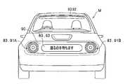
外部表示装置83は、自車両Mの周囲に存する交通参加者(歩行者・自転車・オートバイ・他車両などを含む)宛に各種情報を表示(案内)する機能を有する。図5Aに示すように、自車両Mの前部に設けられた外部表示装置83は、自車両Mにおけるフロントグリル90のうち、車幅方向に離間して設けられる右前部灯火部91A及び左前部灯火部91B、並びに、左右の前部灯火部91A,91Bの間に設けられる前部表示部93を備える。 The
また、自車両Mの前部に設けられた外部表示装置83は、さらに前部インジケータ92を備える。前部インジケータ92は、車両制御装置100の自律走行制御により自車両Mが移動している際、すなわち自車両Mが自動運転により移動している際に、自車両Mの前方に向けて点灯し、自車両Mの前方に存する交通参加者に対して、自車両Mが自動運転により移動している旨を案内する。 Further, the
図5Bに示すように、自車両Mの後部に設けられた外部表示装置83は、自車両Mにおけるリアグリル94のうち車幅方向に離間して設けられる右後部灯火部95A及び左後部灯火部95B、自車両Mの車室内であってリアウインドウ96の中央下部を通して外方から臨み得る位置に設けられる後部表示部97を備える。後部表示部97は、例えば、リアウインドウ96の開口下端部(不図示)などに設けられる。 As shown in FIG. 5B, the
また、自車両Mの後部に設けられた外部表示装置83は、さらに後部インジケータ98を備える。後部インジケータ98は、車両制御装置100の自律走行制御により自車両Mが移動している際、すなわち自車両Mが自動運転により移動している際に、自車両Mの後方に向けて点灯し、自車両Mの後方に存する交通参加者に対して、自車両Mが自動運転により移動している旨を案内する。 Further, the
なお、詳細な説明及び図示を省略するが、自車両Mが自動運転により移動している際に、自車両Mの右方に向けて点灯し、自車両Mの右方に存する交通参加者に対して、自車両Mが自動運転により移動している旨を案内する右部インジケータを設けてもよい。同様に、自車両Mが自動運転により移動している際に、自車両Mの左方に向けて点灯し、自車両Mの左方に存する交通参加者に対して、自車両Mが自動運転により移動している旨を案内する左部インジケータを設けてもよい。 Although detailed explanation and illustration are omitted, when the own vehicle M is moving by automatic driving, the light is turned on toward the right side of the own vehicle M, and the traffic participant who is on the right side of the own vehicle M is lit. On the other hand, a right indicator may be provided to indicate that the own vehicle M is moving by automatic driving. Similarly, when the own vehicle M is moving by automatic driving, the own vehicle M lights up toward the left side of the own vehicle M, and the own vehicle M automatically drives for a traffic participant who is on the left side of the own vehicle M. A left indicator may be provided to indicate that the vehicle is moving.
ここで、外部表示装置83のうち、左右の前部灯火部91A,91Bの構成について、図5Cを参照して説明する。図5Cは、自車両Mに備わる左右の前部灯火部91A,91Bの概略構成を表す正面図である。なお、左右の前部灯火部91A,91Bはその構成が共通のため、図5Cには1つの前部灯火部のみを図示している。以下の図5Cの説明において、右前部灯火部91Aの説明では図5C中の括弧外の符号を参照し、左前部灯火部91Bの説明では図5C中の括弧内の符号を参照するものとする。 Here, the configurations of the left and right front lighting portions 91A and 91B of the
右前部灯火部91Aは、正面視で円形状に形成されている。右前部灯火部91Aは、その外径寸法と比べて小径の寸法を呈する正面視で円形状に形成されたヘッドランプ91Aaを中心に、それぞれが円環状に形成された方向指示器91Ab、灯火表示部91Ac、ポジションランプ91Adを、径方向の外方に向かって順次同心円状に配設して構成されている。 The right front lighting portion 91A is formed in a circular shape when viewed from the front. The right front lighting unit 91A has a headlamp 91Aa formed in a circular shape in a front view, which has a smaller diameter than the outer diameter dimension, and a direction indicator 91Ab and a lighting display, each of which is formed in an annular shape. The portion 91Ac and the position lamp 91Ad are sequentially arranged concentrically toward the outside in the radial direction.
ヘッドランプ91Aaは、自車両Mが暗所を走行中に、その進行方向前方に光を照射して乗員の前方視界を補助する役割を果たす。方向指示器91Abは、自車両Mが右左折する際に、その意図を自車両Mの周囲に存する交通参加者宛に伝える役割を果たす。灯火表示部91Acは、例えば、前部表示部93の表示内容と相まって、自車両Mの利用者(所有者を含む)とのコミュニケーションに供される。ポジションランプ91Adは、自車両Mが暗所を走行中に、自車両Mの車幅を周囲に存する交通参加者宛に伝える役割を果たす。 The headlamp 91Aa plays a role of assisting the front view of the occupant by irradiating light in front of the traveling direction while the own vehicle M is traveling in a dark place. The direction indicator 91Ab serves to convey the intention to the traffic participants around the own vehicle M when the own vehicle M turns left or right. The light display unit 91Ac, for example, is used for communication with a user (including the owner) of the own vehicle M in combination with the display content of the front display unit 93. The position lamp 91Ad plays a role of transmitting the width of the own vehicle M to the traffic participants in the surroundings while the own vehicle M is traveling in a dark place.
左前部灯火部91Bも、右前部灯火部91Aと同様に、正面視で円形状に形成されたヘッドランプ91Baを中心に、それぞれが円環状に形成された方向指示器91Bb、灯火表示部91Bc、ポジションランプ91Bdを、径方向の外方に向かって順次同心円状に配設して構成されている。左右の前部灯火部91A,91B(例えば左右の灯火表示部91Ac,91Bc)は、後述する情報提示部331による情報提示に用いられる。 Similar to the right front lighting unit 91A, the left front lighting unit 91B also has a turn signal 91Bb and a lighting display unit 91Bc, each of which is formed in an annular shape around a headlamp 91Ba formed in a circular shape in a front view. The position lamps 91Bd are sequentially arranged concentrically toward the outside in the radial direction. The left and right front lighting units 91A and 91B (for example, the left and right lighting display units 91Ac and 91Bc) are used for information presentation by the
〔車両制御装置100の構成〕
次に、図2に戻って、車両制御装置100の構成について説明する。
車両制御装置100は、例えば、一以上のプロセッサ又は同等の機能を有するハードウェアにより実現される。車両制御装置100は、CPU(Central Processing Unit)などのプロセッサ、記憶装置、及び通信インターフェースが内部バスによって接続されたECU(Electronic Control Unit)、又はMPU(Micro-Processing Unit)などが組み合わされた構成であってよい。[Structure of vehicle control device 100]
Next, returning to FIG. 2, the configuration of the
The
車両制御装置100は、目標車線決定部110と、運転支援制御部120と、走行制御部160と、HMI制御部170と、記憶部180と、を備える。
目標車線決定部110、運転支援制御部120の各部の機能、及び走行制御部160のうち一部又は全部の機能は、プロセッサがプログラム(ソフトウェア)を実行することにより実現される。また、これらの機能のうち一部又は全部は、LSI(Large Scale Integration)やASIC(Application Specific Integrated Circuit)などのハードウェアによって実現されてもよいし、ソフトウェアとハードウェアの組み合わせによって実現されてもよい。The
The functions of the target
以降の説明において、「○○部は」と主体を記した場合、運転支援制御部120が必要に応じROM・EEPROM(Electrically Erasable Programmable Read-Only Memory)から各プログラムを読み出した上でRAMにロードし、各機能(後述)を実行するものとする。各プログラムは、予め記憶部180に記憶されていてもよいし、他の記憶媒体又は通信媒体を介して、必要に応じて車両制御装置100に取り込まれてもよい。 In the following explanation, when the main body is described as "○○ part is", the driving
[目標車線決定部110]
目標車線決定部110は、例えば、MPU(Micro Processing Unit)により実現される。目標車線決定部110は、ナビゲーション装置20から提供された経路を複数のブロックに分割し(例えば、車両進行方向に関して100[m]毎に分割し)、高精度地図情報181を参照してブロックごとに目標車線を決定する。目標車線決定部110は、例えば、左から何番目の車線を走行するといった決定を行う。目標車線決定部110は、例えば、経路において分岐箇所や合流箇所などが存在する場合、自車両Mが、分岐先に進行するための合理的な走行経路を走行できるように、目標車線を決定する。目標車線決定部110により決定された目標車線は、目標車線情報182として記憶部180に記憶される。[Target lane determination unit 110]
The target
[運転支援制御部120]
運転支援制御部120は、運転支援モード制御部130と、認識部140と、切替制御部150と、を備える。[Driving support control unit 120]
The driving
<運転支援モード制御部130>
運転支援モード制御部130は、HMI35に対するドライバの操作、行動計画生成部144により決定されたイベント、軌道生成部147により決定された走行態様などに基づいて、運転支援制御部120が実行する自動運転モード(自動運転支援状態)を決定する。自動運転モードは、HMI制御部170に通知される。<Driving support mode control unit 130>
The driving support mode control unit 130 is an automatic driving executed by the driving
いずれの自動運転モードにおいても、HMI35における運転操作系の構成要素に対する操作によって、下位の自動運転モードに切替える(オーバーライドする)ことができる。
オーバーライドは、例えば、自車両MのドライバによるHMI35の運転操作系の構成要素に対する操作が、所定時間を超えて継続した場合、所定の操作変化量(例えばアクセルペダル41によるアクセル開度、ブレーキペダル47によるブレーキ踏量、ステアリングホイール55によるステアリング操舵角)を超える場合、又は、運転操作系の構成要素に対する操作を所定の回数を超えて行った場合などに開始される。In any of the automatic operation modes, it is possible to switch (override) to a lower automatic operation mode by operating the components of the operation operation system in the
The override is, for example, when the driver of the own vehicle M continues to operate the components of the driving operation system of the
<認識部140>
認識部140は、自車位置認識部141と、外界認識部142と、エリア特定部143と、行動計画生成部144と、軌道生成部147と、を備える。<
The
<自車位置認識部141>
自車位置認識部141は、記憶部180に格納された高精度地図情報181と、カメラ11、レーダ13、ライダ15、ナビゲーション装置20、又は車両センサ30から入力される情報とに基づいて、自車両Mが走行している走行車線、及び、走行車線に対する自車両Mの相対位置を認識する。<Own vehicle
The own vehicle
自車位置認識部141は、高精度地図情報181から認識される道路区画線のパターン(例えば実線と破線の配列)と、カメラ11によって撮像された画像から認識される自車両Mの周辺の道路区画線のパターンとを比較することで、走行車線を認識する。この認識において、ナビゲーション装置20から取得される自車両Mの現在位置やINSによる処理結果が加味されてもよい。 The own vehicle
<外界認識部142>
外界認識部142は、図2に示すように、カメラ11、レーダ13、ライダ15を含む外界センサ10から入力される外界情報に基づいて、例えば、周辺車両の位置・車速・加速度を含む外界状態を認識する。周辺車両とは、例えば、自車両Mの周辺を走行する車両であって、自車両Mと同じ方向に走行する他車両(後述の前走車及び後走車)である。
周辺車両の位置は、他車両の重心やコーナーなどの代表点で表されてもよいし、他車両の輪郭で表現された領域で表されてもよい。周辺車両の状態とは、上記各種機器の情報に基づいて把握される、周辺車両の速度・加速度、車線変更をしているか否か(あるいは車線変更をしようとしているか否か)を含んでもよい。また、外界認識部142は、前走車及び後走車を含む周辺車両に加えて、ガードレール、電柱、駐車車両、歩行者、交通標識を含む物標の位置を認識する構成を採用してもよい。
本実施形態において、周辺車両のうち自車両Mと共通の走行レーンかつ自車両Mの直前を走行する車両であって、追従走行制御において追従対象となる車両を「前走車」と呼ぶ。また、周辺車両のうち自車両Mと共通の走行レーンかつ自車両Mの直後を走行する車両を「後走車」と呼ぶ。<
As shown in FIG. 2, the outside
The position of the peripheral vehicle may be represented by a representative point such as the center of gravity or a corner of the other vehicle, or may be represented by a region represented by the outline of the other vehicle. The state of the peripheral vehicle may include the speed / acceleration of the peripheral vehicle and whether or not the vehicle is changing lanes (or whether or not the vehicle is trying to change lanes), which is grasped based on the information of the various devices. Further, the outside
In the present embodiment, among the peripheral vehicles, a vehicle having a traveling lane common to the own vehicle M and traveling immediately in front of the own vehicle M and being a follow-up target in the follow-up travel control is referred to as a "preceding vehicle". Further, among the peripheral vehicles, a vehicle having a traveling lane common to the own vehicle M and traveling immediately after the own vehicle M is referred to as a "rear vehicle".
<エリア特定部143>
エリア特定部143は、自車両Mの周辺に存する特定エリア(インターチェンジ:IC/ジャンクション:JCT/車線の増加・減少地点)に係る情報を地図情報に基づき取得する。これにより、エリア特定部143は、前走車を含む前方車両に隠れて進行方向画像を外界センサ10を介して取得できない場合でも、自車両Mの円滑な進行を補助する特定エリアに係る情報を取得することができる。<
The
なお、エリア特定部143は、地図情報に基づく特定エリアに係る情報の取得に代えて、外界センサ10を介して取得した進行方向画像に基づく画像処理によって物標を同定することにより、又は、外界認識部142の内部処理によって進行方向画像の輪郭に基づいて物標を認識することにより、前記特定エリアに係る情報を取得しても構わない。
また、後述するように、通信装置25が入手したVICS情報を用いて、エリア特定部143が取得した特定エリアに係る情報の精度を高める構成を採用しても構わない。The
Further, as will be described later, a configuration may be adopted in which the VICS information obtained by the
<行動計画生成部144>
行動計画生成部144は、自動運転のスタート地点、及び/又は自動運転の目的地を設定する。自動運転のスタート地点は、自車両Mの現在位置であってもよいし、自動運転を指示する操作がなされた地点であってもよい。行動計画生成部144は、そのスタート地点と自動運転の目的地との間の区間において、行動計画を生成する。なお、これに限らず、行動計画生成部144は、任意の区間について行動計画を生成してもよい。<Action
The action
行動計画は、例えば、順次実行される複数のイベントで構成される。複数のイベントには、例えば、自車両Mを減速させる減速イベントや、自車両Mを加速させる加速イベント、走行車線を逸脱しないように自車両Mを走行させるレーンキープイベント、走行車線を変更させる車線変更イベント、自車両Mに前走車を追い越させる追い越しイベント、分岐ポイントにおいて所望の車線に変更させたり、現在の走行車線を逸脱しないように自車両Mを走行させたりする分岐イベント、本線に合流するための合流車線において自車両Mを加減速させ、走行車線を変更させる合流イベント、自動運転の開始地点で手動運転モードから自動運転モード(自動運転支援状態)に移行させたり、自動運転の終了予定地点で自動運転モードから手動運転モードに移行させたりするハンドオーバイベントなどが含まれる。 An action plan consists of, for example, a plurality of events that are executed sequentially. The plurality of events include, for example, a deceleration event for decelerating the own vehicle M, an acceleration event for accelerating the own vehicle M, a lane keeping event for driving the own vehicle M so as not to deviate from the driving lane, and a lane for changing the driving lane. Change event, overtaking event to let own vehicle M overtake the preceding vehicle, branch event to change to the desired lane at the branch point or drive own vehicle M so as not to deviate from the current driving lane, join the main lane A merging event that accelerates or decelerates the own vehicle M in the merging lane to change the driving lane, shifts from the manual driving mode to the automatic driving mode (automatic driving support state) at the start point of the automatic driving, or ends the automatic driving. It includes a handover event that shifts from the automatic operation mode to the manual operation mode at the scheduled point.
行動計画生成部144は、目標車線決定部110により決定された目標車線が切替わる箇所において、車線変更イベント、分岐イベント、又は合流イベントを設定する。行動計画生成部144によって生成された行動計画を示す情報は、行動計画情報183として記憶部180に格納される。 The action
行動計画生成部144は、モード変更部145と、報知制御部146とを備える。
<モード変更部145>
モード変更部145は、例えば、外界認識部142による自車両Mの進行方向に存する物標に認識結果に基づいて、予め設定される複数段階の自動運転モード及び手動運転モードを含む運転モードのなかから、前記認識結果に相応しい運転モードを選択し、当該選択した運転モードを用いて自車両Mの運転動作を行わせる。The action
<
The
<報知制御部146>
報知制御部146は、モード変更部145によって自車両Mの運転モードが遷移された場合、自車両Mの運転モードが遷移した旨を報知する。報知制御部146は、例えば、記憶部180に予め記憶される音声情報をスピーカ63に出力させることにより、自車両Mの運転モードが遷移した旨を報知する。
なお、自車両Mの運転モードの遷移をドライバに報知することが可能であれば、音声による報知に限らず、表示、発光、振動、又はこれらの組み合わせによって前記報知を行っても構わない。<
When the operation mode of the own vehicle M is changed by the
If it is possible to notify the driver of the transition of the operation mode of the own vehicle M, the notification may be performed not only by voice but also by display, light emission, vibration, or a combination thereof.
<軌道生成部147>
軌道生成部147は、行動計画生成部144で生成された行動計画に基づいて、自車両Mの走行すべき軌道を生成する。<
The
<切替制御部150>
切替制御部150は、図2に示すように、自動運転切替スイッチ71(図3参照)から入力される信号、その他に基づいて自動運転モード及び手動運転モードを相互に切替える。また、切替制御部150は、HMI35における運転操作系の構成要素に対する加速、減速又は操舵を指示する操作に基づいて、その時の自動運転モードを下位の運転モードに切替える。例えば、切替制御部150は、HMI35における運転操作系の構成要素から入力された信号の示す操作量が閾値を超えた状態が、基準時間以上継続した場合に、その時の自動運転モードを下位の運転モードに切替える(オーバーライド)。
また、切替制御部150は、オーバーライドによる下位の運転モードへの切替えの後、所定時間の間、HMI35における運転操作系の構成要素に対する操作が検出されなかった場合に、元の自動運転モードに復帰させる切替え制御を行ってもよい。<Switching control unit 150>
As shown in FIG. 2, the switching control unit 150 switches between the automatic operation mode and the manual operation mode based on the signal input from the automatic operation changeover switch 71 (see FIG. 3) and others. Further, the switching control unit 150 switches the automatic operation mode at that time to a lower operation mode based on the operation of instructing acceleration, deceleration, or steering of the components of the operation system in the
Further, the switching control unit 150 returns to the original automatic operation mode when no operation on the components of the operation operation system in the
<走行制御部160>
走行制御部160は、軌道生成部147によって生成された自車両Mの走行すべき軌道を、予定の時刻通りに自車両Mが通過するように、走行駆動力出力装置200、ステアリング装置210、及びブレーキ装置220の制御を行うことにより、自車両Mの走行制御を行う。<Driving
The
<HMI制御部170>
HMI制御部170は、運転支援制御部120により自車両Mの自動運転モードに係る設定情報が通知されると、運転モードごとの使用が許可される装置(ナビゲーション装置20及びHMI35の一部又は全部)と使用が許可されない装置とを表すモード別操作可否情報184を参照して、自動運転モードの設定内容に応じてHMI35を制御する。
HMI制御部170は、図2に示すように、運転支援制御部120から取得した自車両Mの運転モードの情報に基づき、また、モード別操作可否情報184を参照することで、使用が許可される装置(ナビゲーション装置20及びHMI35の一部又は全部)と、使用が許可されない装置とを判別する。また、HMI制御部170は、この判別結果に基づいて、運転操作系のHMI35又はナビゲーション装置20に関するドライバ操作の受け付け可否を制御する。<
When the driving
As shown in FIG. 2, the
例えば、車両制御装置100の実行する運転モードが手動運転モードである場合、HMI制御部170は、運転操作系のHMI35(例えば、アクセルペダル41、ブレーキペダル47、シフトレバー51、及びステアリングホイール55など。図3参照)に関するドライバ操作を受け付ける。 For example, when the operation mode executed by the
HMI制御部170は、表示制御部171を備える。
<表示制御部171>
表示制御部171は、内部表示装置61及び外部表示装置83に関する表示制御を行う。具体的には、例えば、表示制御部171は、車両制御装置100の実行する運転モードが自動化度の高い自動運転モードである場合に、自車両Mの周囲に存する交通参加者に対する注意喚起・警告・運転補助などの情報を内部表示装置61及び/又は外部表示装置83に表示させる制御を行う。これについて、詳しくは後述する。The
<
The
<記憶部180>
記憶部180には、例えば、高精度地図情報181、目標車線情報182、行動計画情報183、モード別操作可否情報184などの情報が格納される。記憶部180は、ROM(Read Only Memory)やRAM(Random Access Memory)、HDD(Hard Disk Drive)、フラッシュメモリなどで実現される。プロセッサが実行するプログラムは、記憶部180に予め格納されていてもよいし、車載インターネット設備などを介して外部装置からダウンロードされてもよい。また、プログラムは、そのプログラムを格納した可搬型記憶媒体が図示しないドライブ装置に装着されることで記憶部180にインストールされてもよい。<
The
高精度地図情報181は、ナビゲーション装置20に通常備わる地図情報と比べて高精度な地図情報である。高精度地図情報181は、例えば、車線の中央の情報、車線の境界の情報などを含んでいる。前記車線の境界には、レーンマークの種別・色・長さ・路幅・路肩幅・本線幅・車線幅・境界位置・境界種別(ガードレール・植栽・縁石)・ゼブラゾーンなどがあり、これらの境界が高精度地図内に含まれている。 The high-
また、高精度地図情報181には、道路情報、交通規制情報、住所情報(住所・郵便番号)、施設情報、電話番号情報などが含まれてよい。道路情報には、高速道路、有料道路、国道、都道府県道といった道路の種別を表す情報や、道路の車線数、各車線の幅員、道路の勾配、道路の位置(経度、緯度、高さを含む3次元座標)、車線のカーブ曲率、車線の合流及び分岐ポイントの位置、道路に設けられた標識などの情報が含まれる。交通規制情報には、工事や交通事故、渋滞などによって車線が封鎖されているといった情報が含まれる。 Further, the high-
[走行駆動力出力装置200、ステアリング装置210、及びブレーキ装置220]
車両制御装置100は、図2に示すように、走行制御部160による走行制御指令に従って、走行駆動力出力装置200、ステアリング装置210、及びブレーキ装置220の駆動を制御する。
<走行駆動力出力装置200>
走行駆動力出力装置200は、自車両Mが走行するための駆動力(トルク)を駆動輪に出力する。走行駆動力出力装置200は、例えば、自車両Mが内燃機関エンジンを動力源とした自動車である場合、内燃機関エンジン、変速機、及び内燃機関エンジンを制御するエンジンECU(Electronic Control Unit:いずれも不図示)を備える。
また、走行駆動力出力装置200は、自車両Mが電動機を動力源とした電気自動車である場合、走行用モータ及び走行用モータを制御するモータECU(いずれも不図示)を備える。
さらに、走行駆動力出力装置200は、自車両Mがハイブリッド自動車である場合、内燃機関エンジン、変速機、エンジンECU、走行用モータ、及びモータECU(いずれも不図示)を備える。[Traveling drive
As shown in FIG. 2, the
<Traveling drive
The traveling driving
Further, when the own vehicle M is an electric vehicle powered by an electric motor, the traveling driving
Further, the traveling driving
走行駆動力出力装置200が内燃機関エンジンのみを含む場合、エンジンECUは、後述する走行制御部160から入力される情報に従って、内燃機関エンジンのスロットル開度やシフト段などを調整する。
走行駆動力出力装置200が走行用モータのみを含む場合、モータECUは、走行制御部160から入力される情報に従って、走行用モータに与えるPWM信号のデューティ比を調整する。
走行駆動力出力装置200が内燃機関エンジン及び走行用モータを含む場合、エンジンECU及びモータECUは、走行制御部160から入力される情報に従って、互いに協調して走行駆動力を制御する。When the traveling driving
When the traveling driving
When the traveling driving
<ステアリング装置210>
ステアリング装置210は、例えば、ステアリングECUと、電動モータ(いずれも不図示)とを備える。電動モータは、例えば、ラックアンドピニオン機構に力を作用させて転舵輪の向きを変更する。ステアリングECUは、車両制御装置100から入力される情報、又は入力されるステアリング操舵角又はステアリングトルクの情報に従って電動モータを駆動し、転舵輪の向きを変更させる。<
The
<ブレーキ装置220>
ブレーキ装置220は、例えば、ブレーキキャリパと、ブレーキキャリパに油圧を伝達するシリンダと、シリンダに油圧を発生させる電動モータと、制動制御部とを備える電動サーボブレーキ装置(いずれも不図示)である。電動サーボブレーキ装置の制動制御部は、走行制御部160から入力される情報に従って電動モータを制御し、制動操作に応じたブレーキトルクが各車輪に出力されるようにする。電動サーボブレーキ装置は、ブレーキペダル47の操作によって発生させた油圧を、マスターシリンダを介してシリンダに伝達する機構をバックアップとして備えてもよい。<
The
なお、ブレーキ装置220は、上記説明した電動サーボブレーキ装置に限らず、電子制御式油圧ブレーキ装置であってもよい。電子制御式油圧ブレーキ装置は、走行制御部160から入力される情報に従ってアクチュエータを制御して、マスターシリンダの油圧をシリンダに伝達する。また、ブレーキ装置220は、走行駆動力出力装置200に含まれ得る走行用モータによる回生ブレーキを含んでもよい。 The
[自動運転車用情報提示装置300のブロック構成]
次に、前述した車両制御装置100に備わる本発明の実施形態に係る自動運転車用情報提示装置300のブロック構成について、図6を参照して説明する。
図6は、本発明の実施形態に係る自動運転車用情報提示装置300の機能を概念的に表すブロック構成図である。[Block configuration of
Next, the block configuration of the
FIG. 6 is a block configuration diagram conceptually showing the function of the
図6に示すように、自動運転車用情報提示装置300は、外界情報取得部311、識別部321、距離算出部322、記憶部323、抽出部325、及び情報提示部331を備えて構成されている。 As shown in FIG. 6, the
<外界情報取得部311>
外界情報取得部311は、外界センサ10で検出された自車両Mの進行方向前方及び進行方向後方を含む自車両Mの周囲に存する物標の分布状況に係る外界情報を取得する機能を有する。なお、外界情報取得部311における外界情報の取得経路としては、外界センサ10に限定されず、ナビゲーション装置20、通信装置25を採用しても構わない。例えば、外界情報取得部311は、外界情報の1つとして、上述した利用者位置情報を、通信装置25から取得してもよい。
外界情報取得部311は、図2に示す車両制御装置100のうち認識部140に相当する機能部材である。<External
The outside world
The outside world
<識別部321>
識別部321は、外界情報取得部311により取得した外界情報に基づいて、自車両Mの周囲に存する人物を探索すると共に、当該探索により抽出した人物が、自車両Mに登録された利用者と一致するか否かを識別する機能を有する。この識別は、例えば、カメラ11に写った人物の顔情報をデータベース(不図示)に登録された利用者の顔情報と照合・認識する顔認識処理を行うことで実現すればよい。
識別部321は、図2に示す車両制御装置100のうち認識部140に相当する機能部材である。<
The
The
<距離算出部322>
距離算出部322は、識別部321により自車両Mの利用者と一致する旨の識別が行われた場合に、外界情報取得部311により取得した外界情報に基づいて、自車両Mから利用者までの距離を算出する機能を有する。例えば、距離算出部322は、自車両Mの現在位置と、取得した利用者位置情報が表す利用者の端末装置の現在位置とに基づいて、自車両Mから利用者までの距離を算出する。これにより、距離算出部322は、自車両Mから利用者までの距離を正確に算出できる。したがって、後述の情報提示部331が、このような確度の高い利用者までの距離に応じた提示態様を用いて、利用者を提示対象とした情報の提示を行うことが可能となる。<
The
なお、上記の例に限らず、距離算出部322は、例えば、カメラ11により撮影した画像の画像解析結果やレーダ13又はライダ15による検出結果などに基づいて、自車両Mから利用者までの距離を算出してもよい。さらに、端末装置からの電波を通信装置25が直接受信できるように構成して、距離算出部322は、通信装置25が受信した端末装置からの電波の受信強度に基づいて、利用者(端末装置)までの距離を算出しても構わない。また、距離算出部322が算出する距離は、自車両Mの現在位置から利用者(又は端末装置)の現在位置までの直線距離であってもよいし、自車両Mの現在位置から利用者(又は端末装置)の現在位置までの経路に沿った距離であってもよい。
距離算出部322は、図2に示す車両制御装置100のうち認識部140に相当する機能部材である。Not limited to the above example, the
The
<記憶部323>
記憶部323は、後述の情報提示部331による情報の提示態様(例えば、左右の前部灯火部91A,91Bや前後部のインジケータ92,98の点灯態様、前部表示部93の表示態様など。以下、「情報提示態様」とも称する)を記憶する機能を有する。記憶部323が記憶する情報提示態様は、自動バレーパーキング方式の駐車場から自車両Mが出庫する際に、利用者を提示対象とした情報の提示を行うための提示態様(以下、「利用者向け提示態様」とも称する)を含む。<
The
詳細は後述するが、自車両Mは、自動バレーパーキング方式の駐車場に駐車されている場合に、利用者からの出庫要請に応じて、当該利用者が自車両Mに乗車可能な乗降場(例えば図9の符号PLを参照)まで自動的に移動する。そして、利用者は、乗降場にて自車両Mに乗車して、駐車場から退場する。このような自動バレーパーキング方式の駐車場では、利用者が、乗降場にて自車両Mの到着を待つといった状況が生じ得る。記憶部323が記憶する利用者向け提示態様は、主に、このような状況において用いることを想定したものとなっている。 Although the details will be described later, when the own vehicle M is parked in the parking lot of the automatic valet parking system, the user can get on and off the own vehicle M in response to a request from the user. For example, it automatically moves to the reference numeral PL in FIG. Then, the user gets on the own vehicle M at the boarding / alighting place and leaves the parking lot. In such an automatic valet parking lot, a situation may occur in which the user waits for the arrival of the own vehicle M at the boarding / alighting place. The presentation mode for users stored by the
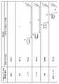
ここで、記憶部323が記憶する利用者向け提示態様の一例について、図7を参照して説明する。図7は、自動運転車用情報提示装置300の記憶部323が記憶する利用者向け提示態様の一例を示す図である。 Here, an example of the presentation mode for the user stored by the
図7に示すように、本実施形態では、「探索中」、「発見」、「ウインク」、「スマイル」、「挨拶」、及び「乗車サイド案内」といった複数の利用者向け提示態様が設けられている。これら利用者向け提示態様のそれぞれは、当該利用者向け提示態様を後述の抽出部325が抽出する条件(以下、「抽出条件」とも称する)と対応付けられた状態で、記憶部323に記憶される。 As shown in FIG. 7, in the present embodiment, presentation modes for a plurality of users such as "searching", "discovery", "wink", "smile", "greeting", and "boarding side guidance" are provided. ing. Each of these presentation modes for users is stored in the
抽出条件は、例えば、自車両Mから利用者までの距離を用いて設定される。これにより、自車両Mから利用者までの距離に応じた利用者向け提示態様を、後述の抽出部325に抽出させ、当該利用者向け提示態様を用いた情報の提示を後述の情報提示部331に行わせることが可能となる。したがって、自動運転車用情報提示装置300は、自車両Mから利用者までの距離に応じた適切な利用者向け提示態様を用いて、利用者を提示対象とした情報の提示を行うことが可能となり、より自然な(よりリアルな)利用者とのコミュニケーションを演出し、利用者に対し、自動運転車への愛着感を湧出・醸成させることが可能となる。 The extraction condition is set by using, for example, the distance from the own vehicle M to the user. As a result, the
また、抽出条件は、さらに、自車両Mにおける利用者の探索状況(例えば自車両Mの周囲に存する人物から利用者が探索されたか否か)も用いて設定される。これにより、自車両Mにおける利用者の探索状況に応じた利用者向け提示態様を、後述の抽出部325に抽出させ、当該利用者向け提示態様を用いた情報の提示を後述の情報提示部331に行わせることが可能となる。したがって、自動運転車用情報提示装置300は、自車両Mにおける利用者の探索状況に応じた適切な利用者向け提示態様を用いて、利用者を提示対象とした情報の提示を行うことが可能となり、より自然な(よりリアルな)利用者とのコミュニケーションを演出し、利用者に対し、自動運転車への愛着感を湧出・醸成させることが可能となる。
なお、「探索中」、「発見」、「ウインク」、「スマイル」、「挨拶」、及び「乗車サイド案内」のそれぞれの利用者向け提示態様による具体的な情報の提示例については、図8A~図8Fを用いて後述する。
記憶部323は、図2に示す車両制御装置100のうち認識部140に属する機能部材である。Further, the extraction condition is also set by using the search status of the user in the own vehicle M (for example, whether or not the user is searched by a person existing around the own vehicle M). As a result, the
In addition, about the presentation example of the specific information by the presentation mode for each user of "searching", "discovery", "wink", "smile", "greeting", and "boarding side guidance", FIG. 8A It will be described later with reference to FIG. 8F.
The
<抽出部325>
抽出部325は、記憶部323に記憶された情報提示態様のなかからいずれかの情報提示態様を抽出する機能を有する。例えば、抽出部325は、識別部321の識別の結果や、距離算出部322により算出された自車両Mから利用者までの距離などに基づいて、記憶部323に記憶された情報提示態様のなかからいずれかの利用者向け提示態様を抽出する。<
The
具体的には、例えば、抽出部325は、識別部321により自車両Mの利用者と一致する旨の識別が行われておらず(すなわち当該利用者がまだ探索されておらず)、当該利用者の探索が行われている際には、抽出条件において利用者の探索状況が「探索時」とされた利用者向け提示態様「探索中」を抽出する。また、抽出部325は、識別部321により自車両Mの利用者と一致する旨の識別が行われた際、すなわち当該利用者が探索(発見)された際には、抽出条件において利用者の探索状況が「発見時」とされた利用者向け提示態様「発見」を抽出する。 Specifically, for example, the
また、抽出部325は、自車両Mの利用者が探索された後、自車両Mから利用者(図7中の符号Uを参照。以下も同様)までの距離が予め定められたD1となった場合には、抽出条件において、利用者の探索状況が「探索後」とされ、且つ利用者までの距離がD1とされた利用者向け提示態様「ウインク」を抽出する。そして、抽出部325は、自車両Mの利用者が探索された後、自車両Mから利用者までの距離が予め定められたD2(ただしD2<D1)となった場合には、抽出条件において、利用者の探索状況が「探索後」とされ、且つ利用者までの距離がD2とされた利用者向け提示態様「スマイル」を抽出する。 Further, after the user of the own vehicle M is searched, the
また、抽出部325は、自車両Mの利用者が探索された後、自車両Mから利用者までの距離が予め定められたD3(ただしD3<D2)となった場合には、抽出条件において、利用者の探索状況が「探索後」とされ、且つ利用者までの距離がD3とされた利用者向け提示態様「挨拶」を抽出する。そして、抽出部325は、自車両Mの利用者が探索された後、自車両Mから利用者までの距離が予め定められたD4(ただしD4<D3)となった場合には、抽出条件において、利用者の探索状況が「探索後」とされ、且つ利用者までの距離がD4とされた利用者向け提示態様「乗車サイド案内」を抽出する。
抽出部325は、図2に示す車両制御装置100のうち認識部140に属する機能部材である。Further, when the distance from the own vehicle M to the user becomes D3 (however, D3 <D2) in advance after the user of the own vehicle M is searched, the
The
<情報提示部331>
情報提示部331は、識別部321による識別の結果、探索により抽出した人物が自車両Mの利用者と一致する旨の識別が行われた場合に、当該利用者を提示対象とした情報の提示を行う機能を有する。この際、情報提示部331は、抽出部325により抽出された情報提示態様により、利用者を提示対象とした情報の提示を行う。
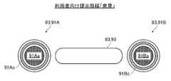
情報提示部331は、自車両Mの右目相当部である右前部灯火部91A(図5A、図5C参照)、自車両Mの左目相当部である左前部灯火部91B(図5A、図5C参照)、及び前部表示部93(図5A参照)を備えて構成されている。
例えば、右前部灯火部91A、左前部灯火部91B、及び前部表示部93は、複数のLED(Light Emitting Diode)照明を集積したLEDパネルによって構成される。情報提示部331は、これらのLEDパネルを、抽出部325により抽出した情報提示態様(例えば利用者向け提示態様)に従って駆動することにより、情報の提示を行う。
情報提示部331は、図2に示す車両制御装置100のうちHMI制御部170に相当する機能部材である。<
When the
The
For example, the right front lighting unit 91A, the left front lighting unit 91B, and the front display unit 93 are composed of an LED panel in which a plurality of LED (Light Emitting Diode) lightings are integrated. The
The
ここで、それぞれの利用者向け提示態様による具体的な情報の提示例について、図8A~図8Fを参照して説明する。 Here, an example of presenting specific information according to each presentation mode for users will be described with reference to FIGS. 8A to 8F.
<利用者向け提示態様「探索中」>
図8Aは、利用者向け提示態様「探索中」による具体的な情報の提示例を示す図である。抽出部325により抽出した情報提示態様が利用者向け提示態様「探索中」であった場合、情報提示部331は、自車両Mを正面視で擬人化した際の目に相当する左右の前部灯火部91A,91Bを用いて、視線のさまよいを表現する。<Presentation mode for users "searching">
FIG. 8A is a diagram showing an example of presenting specific information according to the presentation mode “searching” for users. When the information presentation mode extracted by the
具体的には、円形状の外周縁を呈する左右の前部灯火部91A,91Bは、図5Aに示したように、フロントグリル90における車幅方向の左右の端部に間隔を置いて設けられている。そのため、左右の前部灯火部91A,91Bは、自車両Mを正面視で擬人化した際に、あたかも両目のようにみえる。 Specifically, the left and right front lighting portions 91A and 91B having a circular outer peripheral edge are provided at intervals on the left and right ends of the
そして、図8A(a)に示すように、情報提示部331は、右前部灯火部91Aのうち円環状の右灯火表示部91Acの右半部91AcRを点灯(図8A中、点灯部分を斜線で示す。以下、同じ。)する一方、左半部を消灯する。同様に、左前部灯火部91Bのうち円環状の左灯火表示部91Bcの右半部91BcRを点灯する一方、左半部を消灯する。このようにすると、左右の前部灯火部91A,91Bは、自車両Mを正面視で擬人化した際に、あたかも横目で右方向を見ているようにみえる。 Then, as shown in FIG. 8A, the
また、図8A(b)に示すように、情報提示部331は、右前部灯火部91Aのうち円環状の右灯火表示部91Acの左半部91AcLを点灯する一方、右半部を消灯する。同様に、左前部灯火部91Bのうち円環状の左灯火表示部91Bcの左半部91BcLを点灯する一方、右半部を消灯する。このようにすると、左右の前部灯火部91A,91Bは、自車両Mを正面視で擬人化した際に、あたかも横目で左方向を見ているようにみえる。 Further, as shown in FIG. 8A (b), the
情報提示部331は、上述した図8A(a)及び図8A(b)に示した左右の前部灯火部91A,91Bの点灯を、所定の周期で交互に繰り返す。このようにすると、左右の前部灯火部91A,91Bは、自車両Mを正面視で擬人化した際に、あたかも横目で左右方向をキョロキョロと見ているようにみえ、視線のさまよいを表現できる。 The
<利用者向け提示態様「発見」>
図8Bは、利用者向け提示態様「発見」による具体的な情報の提示例を示す図である。抽出部325により抽出した情報提示態様が利用者向け提示態様「発見」であった場合、情報提示部331は、自車両Mを正面視で擬人化した際の目に相当する左右の前部灯火部91A,91Bを用いて、利用者に対する視線送りを表現する。<Presentation mode "discovery" for users>
FIG. 8B is a diagram showing an example of presentation of specific information by the presentation mode “discovery” for users. When the information presentation mode extracted by the
具体的には、図8Bに示すように、情報提示部331は、右前部灯火部91Aのうち円環状の右灯火表示部91Ac全体を点灯する。同様に、左前部灯火部91Bのうち円環状の左灯火表示部91Bc全体を点灯する。このようにすると、左右の前部灯火部91A,91Bは、自車両Mを正面視で擬人化した際に、あたかも略正面を両目を丸くして見据えているようにみえ、自車両Mの正面にいる利用者に対する視線送りを表現できる。 Specifically, as shown in FIG. 8B, the
なお、利用者向け提示態様「発見」は、前部灯火部91A,91Bの全体を点灯させる例に限らない。例えば、利用者が自車両Mの正面にいるような場合には図8Bに示したように前部灯火部91A,91Bの全体を点灯させ、利用者が自車両Mの右前方にいるような場合には図8A(a)に示したように前部灯火部91A,91Bの右半部91AcR,91BcRのみを点灯させ、利用者が自車両Mの左前方にいるような場合には図8A(b)に示したように前部灯火部91A,91Bの左半部91AcL,91BcLのみを点灯させるようにしてもよい。このようにすれば、自車両Mと利用者との位置関係に応じた適切な視線送りを表現できる。 The presentation mode "discovery" for users is not limited to the example of lighting the entire front lighting units 91A and 91B. For example, when the user is in front of the own vehicle M, the entire front lighting portions 91A and 91B are turned on as shown in FIG. 8B, and the user is in front of the right front of the own vehicle M. In that case, as shown in FIG. 8A (a), only the right half portions 91AcR and 91BcR of the front lighting portions 91A and 91B are turned on, and when the user is in the left front of the own vehicle M, FIG. 8A As shown in (b), only the left half 91AcL and 91BcL of the front lighting portions 91A and 91B may be turned on. By doing so, it is possible to express an appropriate line-of-sight feed according to the positional relationship between the own vehicle M and the user.
<利用者向け提示態様「ウインク」>
図8Cは、利用者向け提示態様「ウインク」による具体的な情報の提示例を示す図である。抽出部325により抽出した情報提示態様が利用者向け提示態様「ウインク」であった場合、情報提示部331は、自車両Mを正面視で擬人化した際の目に相当する左右の前部灯火部91A,91Bを用いて、ウインクを表現する。<Presentation mode "wink" for users>
FIG. 8C is a diagram showing an example of presentation of specific information by the presentation mode “wink” for users. When the information presentation mode extracted by the
具体的には、図8Cに示すように、情報提示部331は、右前部灯火部91Aのうち円環状の右灯火表示部91Ac全体を点灯する。また、情報提示部331は、左前部灯火部91Bのうち円環状の左灯火表示部91Bcの下半部91BcDを点灯する一方、上半部を消灯する。このようにすると、左右の前部灯火部91A,91Bは、自車両Mを正面視で擬人化した際に、あたかも右目は開いて左目は閉じたウインクをしているようにみえ、ウインクを表現できる。 Specifically, as shown in FIG. 8C, the
<利用者向け提示態様「スマイル」>
図8Dは、利用者向け提示態様「スマイル」による具体的な情報の提示例を示す図である。抽出部325により抽出した情報提示態様が利用者向け提示態様「スマイル」であった場合、情報提示部331は、自車両Mを正面視で擬人化した際の目に相当する左右の前部灯火部91A,91Bを用いて、微笑みを表現する。<Presentation mode "Smile" for users>
FIG. 8D is a diagram showing an example of presenting specific information by the presentation mode “smile” for users. When the information presentation mode extracted by the
具体的には、図8Dに示すように、情報提示部331は、右前部灯火部91Aのうち円環状の右灯火表示部91Acのうち上半部91AcUを点灯する一方、下半部を消灯する。同様に、左前部灯火部91Bのうち円環状の左灯火表示部91Bcのうち上半部91BcUを点灯する一方、下半部を消灯する。このようにすると、左右の前部灯火部91A,91Bは、自車両Mを正面視で擬人化した際に、あたかも両目を細めて微笑んでいるようにみえ、微笑みを表現できる。 Specifically, as shown in FIG. 8D, the
<利用者向け提示態様「挨拶」>
図8Eは、利用者向け提示態様「挨拶」による具体的な情報の提示例を示す図である。抽出部325により抽出した情報提示態様が利用者向け提示態様「挨拶」であった場合、情報提示部331は、前部表示部93を用いて、利用者に対する挨拶を表現する。<Presentation mode "greeting" for users>
FIG. 8E is a diagram showing an example of presenting specific information by the presentation mode “greeting” for users. When the information presentation mode extracted by the
具体的には、図8Eに示すように、情報提示部331は、前部表示部93に「おまたせしました」といったメッセージを表示させる。これにより、利用者に対する挨拶を表現できる。なお、このときに表示させるメッセージなどは、利用者を待たせた時間(例えば出庫要請があってから利用者の元へ到着するまでに要した時間)などに応じて適宜変更してもよい。例えば、利用者を待たせた時間が5分未満であれば「おまたせしました」と表示させ、利用者を待たせた時間が5分以上であれば「大変おまたせしました」と表示させるようにしてもよい。 Specifically, as shown in FIG. 8E, the
また、このときに表示させるメッセージなどは、利用者の元へ到着した際の時刻などに応じて適宜変更してもよい。例えば、利用者に到着した際の時刻が、5時から10時までの間は「おはようございます」、10時から17時までの間は「こんにちは」、17時から翌日5時までの間は「こんばんは」といったように表示させてもよい。 Further, the message to be displayed at this time may be appropriately changed according to the time when the user arrives at the user. For example, when the user arrives, the time is "Good morning" from 5:00 to 10:00, "Hello" from 10:00 to 17:00, and from 17:00 to 5:00 the next day. It may be displayed as "Good evening".
また、抽出部325により抽出した情報提示態様が利用者向け提示態様「挨拶」であった場合も、利用者向け提示態様「発見」の場合と同様に、情報提示部331は、自車両Mを正面視で擬人化した際の目に相当する左右の前部灯火部91A,91Bを用いて、利用者に対する視線送りを表現してもよい。図8Eに示す例では、左右の前部灯火部91A,91Bの全体を点灯させることで、自車両Mの正面にいる利用者に対する視線送りを表現している。 Further, even when the information presentation mode extracted by the
<利用者向け提示態様「乗車サイド案内」>
図8Fは、利用者向け提示態様「乗車サイド案内」による具体的な情報の提示例を示す図である。抽出部325により抽出した情報提示態様が利用者向け提示態様「乗車サイド案内」であった場合、情報提示部331は、前部表示部93を用いて、利用者が自車両Mに乗車するにあたって推奨する乗車サイドを案内する。<Presentation mode for users "ride side guidance">
FIG. 8F is a diagram showing an example of presentation of specific information by the presentation mode “boarding side guidance” for users. When the information presentation mode extracted by the
例えば、自車両Mと利用者との位置関係や、自車両Mの周囲の交通状況などに基づいて、自動運転車用情報提示装置300が、自車両Mが備える左右両側のドアのうち左側ドア(例えば助手席側ドア)からの乗車を推奨すると判断したとする。この場合、図8Fに示すように、情報提示部331は、前部表示部93に「左から乗ってください」といったメッセージを表示させる。また、情報提示部331は、例えば、前部表示部93の左端部93Lを点灯させてもよい。このようにすれば、利用者に対し、自車両Mに乗車するにあたって推奨する乗車サイドを、より直感的に案内できる。 For example, based on the positional relationship between the own vehicle M and the user, the traffic conditions around the own vehicle M, and the like, the
[自動運転車Mの動作]
次に、自動運転車Mの動作の一例について説明する。前述したように、自動運転車Mは、自動バレーパーキング方式の駐車場に駐車可能である。ここで、自動バレーパーキング方式の駐車場の一例について、図9を参照して説明する。図9は、自動バレーパーキング方式の駐車場の一例を示す図である。[Operation of self-driving car M]
Next, an example of the operation of the self-driving car M will be described. As described above, the self-driving car M can be parked in the parking lot of the automatic valet parking system. Here, an example of an automatic valet parking type parking lot will be described with reference to FIG. FIG. 9 is a diagram showing an example of an automatic valet parking type parking lot.
図9に示すように、自動バレーパーキング方式の駐車場の一例である駐車場PAは、利用者の訪問先となる訪問先施設(例えばホテルや百貨店)に併設され、自動運転車Mなどの車両を駐車可能な複数の駐車スペースPSと、駐車場PAに駐車される車両の利用者が当該車両から乗降可能な乗降場PLと、を備える。以下、自動運転車Mの利用者が駐車場PAを利用する場合の例について説明する。 As shown in FIG. 9, the parking lot PA, which is an example of an automatic valet parking type parking lot, is installed in a visiting facility (for example, a hotel or a department store) to be visited by a user, and is a vehicle such as an automated driving vehicle M. It is provided with a plurality of parking space PS capable of parking, and a boarding / alighting area PL at which a user of a vehicle parked in the parking lot PA can get on / off the vehicle. Hereinafter, an example in which the user of the self-driving car M uses the parking lot PA will be described.
利用者は、自車両Mの駐車場PAへの駐車に先立ち、端末装置などを用いて、駐車場PAを管理する駐車場管理サーバSVに対して駐車場PAの利用予約(以下、「駐車予約」とも称する)を行う。この駐車予約により、利用者は、駐車場PAを利用する利用日時(すなわち自車両Mを駐車場PAに駐車する日時)や、自車両Mの識別子である車両ID(例えば自車両Mのナンバープレートのナンバー)などを駐車場管理サーバSVに登録する。 Prior to parking the own vehicle M in the parking lot PA, the user makes a reservation for using the parking lot PA to the parking lot management server SV that manages the parking lot PA by using a terminal device or the like (hereinafter, "parking reservation"). Also called). By this parking reservation, the user can use the parking lot PA (that is, the date and time when the own vehicle M is parked in the parking lot PA) and the vehicle ID which is an identifier of the own vehicle M (for example, the license plate of the own vehicle M). Number) etc. are registered in the parking lot management server SV.
その後、駐車予約により駐車場管理サーバSVに登録した利用日時となると、利用者は、乗降場PLに自車両Mを乗り付けて、乗降場PLにて自車両Mから降車する。自車両Mは、利用者の降車後、自動運転により駐車場PA内の所定の駐車スペースPSまで移動する自走入庫イベントを開始する。この自走入庫イベントは、例えば、利用者が端末装置などを用いて駐車場管理サーバSVに対し入庫要請を送り、この入庫要請を受けた駐車場管理サーバSVが自車両Mに対し移動先となる駐車スペースPSを指示する入庫指示を送信することで開始される。自走入庫イベントを開始した自車両Mは、外界センサ10によるセンシングなどを行いながら、駐車場管理サーバSVにより指定された駐車スペースPSまで自動運転により移動する。 After that, when the usage date and time registered in the parking lot management server SV by the parking reservation comes, the user rides the own vehicle M on the boarding / alighting area PL and gets off from the own vehicle M at the boarding / alighting area PL. After the user gets off the vehicle M, the own vehicle M starts a self-propelled warehousing event that moves to a predetermined parking space PS in the parking lot PA by automatic driving. In this self-propelled warehousing event, for example, the user sends a warehousing request to the parking lot management server SV using a terminal device or the like, and the parking lot management server SV receiving the warehousing request serves as a destination for the own vehicle M. It is started by transmitting a warehousing instruction instructing the parking space PS. The own vehicle M, which has started the self-propelled warehousing event, automatically moves to the parking space PS designated by the parking lot management server SV while performing sensing by the
また、駐車場PAに駐車された自車両Mは、利用者からの出庫要請に応じて、乗降場PLまで移動する自走出庫イベントを開始する。この自走出庫イベントは、例えば、利用者が端末装置などを用いて駐車場管理サーバSVに対し出庫要請を送り、この出庫要請を受けた駐車場管理サーバSVが自車両Mに対し乗降場PLまで移動するように指示する出庫指示を送信することで開始される。自走出庫イベントを開始した自車両Mは、外界センサ10によるセンシングなどを行いながら、乗降場PLまで自動運転により移動する。そして、自車両Mは、乗降場PLに到着すると利用者を探索し、利用者が探索(発見)できた場合には当該利用者の元まで移動する。利用者は、乗降場PLにて自車両Mに乗車して、駐車場PAから退場する。 In addition, the own vehicle M parked in the parking lot PA starts a self-propelled warehousing event that moves to the boarding / alighting area PL in response to a warehousing request from the user. In this self-propelled warehousing event, for example, the user sends a warehousing request to the parking lot management server SV using a terminal device or the like, and the parking lot management server SV receiving the warehousing request gets on and off the vehicle M. It is started by sending a shipping instruction instructing you to move to. The own vehicle M, which has started the self-propelled delivery event, moves to the boarding / alighting area PL by automatic driving while performing sensing by the
以下、自動バレーパーキング方式の駐車場PAから出庫する際の自動運転車Mの動作の一例について、図10を参照して説明する。
図10は、自動バレーパーキング方式の駐車場PAから出庫する際の自動運転車Mの車両制御装置100の動作説明に供するフローチャート図である。Hereinafter, an example of the operation of the autonomous driving vehicle M when leaving the parking lot PA of the automatic valet parking system will be described with reference to FIG.
FIG. 10 is a flowchart for explaining the operation of the
図10に示すステップS11において、自動バレーパーキング方式の駐車場PAに駐車中の自動運転車Mの車両制御装置100は、利用者からの出庫要請があったか否かを判定する。例えば、自車両Mに対し駐車場管理サーバSVから乗降場PLまで移動する旨の出庫指示があった場合に、車両制御装置100は、ステップS11において肯定判定し、処理の流れを次のステップS12へ進ませる。
一方、自車両Mに対し駐車場管理サーバSVからの出庫指示がなかった場合に、車両制御装置100は、ステップS11において否定判定し、駐車場管理サーバSVからの出庫指示があるまでステップS11の処理を繰り返す。In step S11 shown in FIG. 10, the
On the other hand, when the own vehicle M is not instructed to leave the parking lot management server SV, the
ステップS12において、車両制御装置100は、外界センサ10によるセンシングなどを行いながら、自車両Mを乗降場PLへ向けて移動させる。 In step S12, the
ステップS13において、車両制御装置100は、自車両Mが乗降場PLに到着したか否かを判定する。ステップS13の判定の結果、自車両Mが乗降場PLに到着したと判定した場合、車両制御装置100は、処理の流れを次のステップS14へ進ませる。
一方、ステップS13の判定の結果、自車両Mが乗降場PLに到着していないと判定した場合、車両制御装置100は、自車両Mが乗降場PLに到着したと判定するまでステップS12及びステップS13の処理を繰り返す。In step S13, the
On the other hand, if it is determined that the own vehicle M has not arrived at the boarding / alighting area PL as a result of the determination in step S13, the
ステップS14において、外界情報取得部311は、外界センサ10で検出された自車両Mの進行方向前方及び進行方向後方を含む自車両Mの周囲に存する物標の分布状況に係る外界情報を取得する。 In step S14, the outside world
ステップS15において、識別部321は、外界情報取得部311により取得した外界情報に基づいて、自車両Mの周囲に存する人物を探索する。 In step S15, the
ステップS16において、識別部321は、ステップS15の探索により抽出した人物が、自車両Mに登録された利用者と一致するか否かを識別する。 In step S16, the
ステップS17において、ステップS16の識別の結果、ステップS15の探索により抽出した人物が、自車両Mに登録された利用者と一致する旨の識別をした場合に、車両制御装置100は、処理の流れを次のステップS18へ進ませる。
一方、ステップS16の識別の結果、ステップS15の探索により抽出した人物が、自車両Mに登録された利用者と一致しない旨の識別をした場合に、車両制御装置100は、処理の流れをステップS23へ進ませる。In step S17, as a result of the identification in step S16, when the person extracted by the search in step S15 is identified to match the user registered in the own vehicle M, the
On the other hand, as a result of the identification in step S16, when it is identified that the person extracted by the search in step S15 does not match the user registered in the own vehicle M, the
ステップS18において、自動運転車用情報提示装置300は、利用者向け提示態様「発見」を用いた情報提示を実行する。具体的には、利用者向け提示態様「発見」を抽出部325により抽出し、利用者向け提示態様「発見」による情報提示(図8B参照)を情報提示部331により実行する。 In step S18, the
ステップS19において、車両制御装置100は、外界センサ10によるセンシングなどを行いながら、自車両Mを利用者の元へ向けて移動させる。 In step S19, the
ステップS20において、距離算出部322は、自車両Mから利用者までの距離を算出する。 In step S20, the
ステップS21において、自動運転車用情報提示装置300は、距離算出部322により算出した利用者までの距離に応じた利用者向け提示態様を用いた情報提示を実行する。具体的には、図7に示した利用者向け提示態様のうち、利用者の探索状況が「探索後」であり、且つ直近のステップS20で算出された距離に対応する利用者向け提示態様を抽出部325により抽出し、当該利用者向け提示態様による情報提示(図8C~図8F参照)を情報提示部331により実行する。 In step S21, the
ステップS22において、車両制御装置100は、自車両Mが利用者の元に到着したか否かを判定する。ステップS22の判定の結果、自車両Mが利用者の元に到着していないと判定した場合、車両制御装置100は、自車両Mが利用者の元に到着したと判定するまでステップS19~ステップS22の処理を繰り返す。 In step S22, the
また、ステップS23において、自動運転車用情報提示装置300は、利用者向け提示態様「探索中」を用いた情報提示を実行する。具体的には、利用者向け提示態様「探索中」を抽出部325により抽出し、利用者向け提示態様「探索中」による情報提示(図8A参照)を情報提示部331により実行する。 Further, in step S23, the
以上説明したように、自動運転車用情報提示装置300によれば、識別部321による識別の結果、探索により抽出した人物が利用者と一致する旨の識別が行われた場合に、情報提示部331は、利用者を提示対象とした情報の提示を行うと共に、利用者を提示対象とした情報の提示態様を自車両Mから利用者までの距離に応じて変化させる。これにより、自動運転車用情報提示装置300は、自車両Mから利用者までの距離に応じた適切な利用者向け提示態様を用いて、利用者を提示対象とした情報の提示を行うことが可能となり、より自然な(よりリアルな)利用者とのコミュニケーションを演出し、利用者に対し、自動運転車への愛着感を湧出・醸成させることが可能となる。 As described above, according to the
また、例えば、自動バレーパーキング方式の駐車場PAの乗降場PLには、多数の車両が集まることがある。このような場合、自動運転車Mの利用者は、自動運転車Mを乗降場PLに呼び出した際に、乗降場PLにいるどの車両が自動運転車M(すなわち自身の車両)であるかを直ちに判別することは難しくなる。特に、自動運転車Mと同種、あるいは自動運転車Mと形状が似た他の車両が乗降場PLにいる場合、利用者による上記の判別はより困難になる。 Further, for example, a large number of vehicles may gather at the boarding / alighting area PL of the parking lot PA of the automatic valet parking system. In such a case, when the user of the self-driving car M calls the self-driving car M to the boarding / alighting place PL, which vehicle in the boarding / alighting place PL is the self-driving car M (that is, his / her own vehicle). It becomes difficult to distinguish immediately. In particular, when another vehicle of the same type as the autonomous driving vehicle M or having a shape similar to that of the autonomous driving vehicle M is in the boarding / alighting area PL, the above determination by the user becomes more difficult.
しかしながら、自動運転車用情報提示装置300は、利用者を提示対象とした情報の提示態様を自車両Mから利用者までの距離に応じて変化させることで、その提示態様からどの車両が自動運転車Mであるかを、利用者に対して直感的にわかり易く示唆できる。すなわち、このようにすることで、あたかも人同士の待ち合わせのように、乗降場PLにて自動運転車Mを待つ利用者の元に自動運転車Mが表情等を変えながら向かってくるかのように演出できる。これにより、自動運転車Mにおける情報の提示態様からどの車両が自動運転車Mであるかを利用者にわかり易く示唆して、利用者による上記の判別を支援できる。したがって、利用者の利便性の向上を図ることができる。 However, the
なお、本発明は、前述した実施形態に限定されるものではなく、適宜、変形、改良、等が可能である。 The present invention is not limited to the above-described embodiment, and can be appropriately modified, improved, and the like.
例えば、駐車場PAからの出庫にあたり、利用者が自車両Mよりも先に乗降場PLに到着する場合と、自車両Mが利用者よりも先に乗降場PLに到着する場合と、が考えられる。そこで、情報提示部331は、利用者が自車両Mよりも先に乗降場PLに到着した場合と、自車両Mが利用者よりも先に乗降場PLに到着した場合とで、前記利用者を提示対象とした情報の提示態様を異ならせてもよい。具体的に、例えば、利用者が自車両Mよりも先に乗降場PLに到着した場合には、情報提示部331は、利用者向け提示態様「挨拶」による情報提示を実行する際に、前部表示部93に「おまたせしました」と表示させる。一方、自車両Mが利用者よりも先に乗降場PLに到着した場合には、情報提示部331は、利用者向け提示態様「挨拶」による情報提示を実行する際に、前部表示部93に「おまちしていました」と表示させる。このようにすれば、より自然な(よりリアルな)利用者とのコミュニケーションを演出でき、一層と自動運転車Mへの愛着感を利用者に湧出・醸成させることが可能となる。 For example, when leaving the parking lot PA, there are cases where the user arrives at the boarding / alighting area PL before the own vehicle M and cases where the own vehicle M arrives at the boarding / alighting area PL before the user. Will be. Therefore, the
また、前述した実施形態では、左右の前部灯火部91A,91B、及び前部表示部93を用いて利用者に向けた情報提示を実行する例を説明したが、これに限らない。例えば、利用者が自車両Mの後方に現れることも考えられる。そこで、情報提示部331は、自車両Mと利用者との位置関係に応じて、利用者を提示対象とした情報の提示を行う場合に用いる外部表示装置83を切り替えるようにしてもよい。具体的には、利用者が自車両Mの前方に位置する場合には、情報提示部331は、左右の前部灯火部91A,91B、前部表示部93、及び前部インジケータ92などを用いて、利用者を提示対象とした情報の提示を行う。一方、利用者が自車両Mの後方に位置する場合には、情報提示部331は、左右の後部灯火部95A,95B、後部表示部97、及び後部インジケータ98などを用いて、利用者を提示対象とした情報の提示を行う。このようにすれば、自車両Mと利用者との位置関係に応じた適切な外部表示装置83を用いて、利用者を提示対象とした情報の提示を行うことができるので、利用者とのコミュニケーションを図ることができる。 Further, in the above-described embodiment, an example of executing information presentation to the user by using the left and right front lighting units 91A and 91B and the front display unit 93 has been described, but the present invention is not limited to this. For example, it is conceivable that the user appears behind the own vehicle M. Therefore, the
また、情報提示部331は、自車両Mから利用者が降車する場合に、利用者を提示対象として当該利用者のスケジュールに応じた情報の提示をさらに行うようにしてもよい。例えば、情報提示部331は、乗降場PLにて利用者が自車両Mから降車した際に、「○時に迎えに来ますね」といったメッセージを前部表示部93に表示してもよい。ここで、「○時」は、例えば、自車両Mが駐車場PAから出庫する予定の時刻であり、駐車場PAの利用予約の際に利用者により登録された時刻である。このようにすれば、利用者のスケジュールに応じた適切な情報を利用者に提示でき、利用者の利便性を向上させることができる。また、利用者のスケジュールに応じた情報の提示は、上記の例に限らず、例えば、利用者が降車後に自車両Mを再度利用する場合は「またあとでね」といったメッセージを前部表示部93に表示させたり、利用者が自車両Mを再度利用するまでに所定時間以上かかるときは「またねバイバイ」といったメッセージを前部表示部93に表示させたりするようにしてもよい。なお、利用者のスケジュールは、通信装置25を介して、利用者の端末装置や駐車場管理サーバSVなどから取得することができる。 Further, when the user gets off from the own vehicle M, the
また、情報提示部331は、利用者を提示対象とした情報を提示するにあたって、自車両Mから利用者までの距離だけでなく、自車両Mの車速も考慮するようにしてもよい。例えば、情報提示部331は、自車両Mから利用者までの距離が所定距離以下になり、且つ自車両Mの車速が所定速度以下となった場合に、利用者を提示対象とした情報の提示を開始するようにしてもよい。 Further, the
また、前述した実施形態では、識別部321による識別が、カメラ11に写った人物の顔情報をデータベースに登録された利用者の顔情報と照合・認識する顔認識処理を行うことで実現可能であることに言及したが、これに限らない。識別部321による識別は、例えば、利用者の所持しているスマートキーとの間で利用者識別処理を行うことで実現してもよい。 Further, in the above-described embodiment, the identification by the
本発明は、前述した実施形態に係る1以上の機能を実現するプログラムを、ネットワーク又は記憶媒体を介してシステム又は装置に供給し、そのシステム又は装置のコンピュータにおける1以上のプロセッサがプログラムを読出し実行する形態でも実現することができる。また、1以上の機能を実現するハードウェア回路(例えば、ASIC)によって実現しても構わない。各機能を実現するプログラムを含む情報は、メモリ、ハードディスクなどの記録装置、メモリカード、光ディスクなどの記録媒体に保持することができる。 The present invention supplies a program that realizes one or more functions according to the above-described embodiment to a system or an apparatus via a network or a storage medium, and one or more processors in the computer of the system or the apparatus read and execute the program. It can also be realized in the form of Further, it may be realized by a hardware circuit (for example, ASIC) that realizes one or more functions. Information including a program that realizes each function can be stored in a recording device such as a memory or a hard disk, or a recording medium such as a memory card or an optical disk.
本明細書には少なくとも以下の事項が記載されている。なお、括弧内には、前述した実施形態において対応する構成要素等を示しているが、これに限定されるものではない。 At least the following matters are described in the present specification. The components and the like corresponding to the above-described embodiments are shown in parentheses, but the present invention is not limited thereto.
(1) 自車両の周囲に存する物標を含む外界情報を取得し、当該取得した外界情報に基づいて自車両の行動計画を生成し、当該生成した行動計画に従って自動的に移動する自動運転車(自動運転車M)に用いられ、自車両の周囲に存する人物に情報の提示を行う自動運転車用情報提示装置(自動運転車用情報提示装置300)であって、
前記自動運転車は、自車両の利用者からの要請に応じて、当該利用者が自車両に乗車可能な所定位置(乗降場PL)まで自動的に移動し、
前記所定位置において、前記外界情報に基づいて、自車両の周囲に存する人物を探索し、当該探索により抽出した人物が前記利用者と一致するか否かを識別する識別部(識別部321)と、
自車両の周囲に存する人物に向けた情報の提示を、自車両が備える外部表示装置(外部表示装置83)を用いて行う情報提示部(情報提示部331)と、
を備え、
前記識別部による識別の結果、前記探索により抽出した人物が前記利用者と一致する旨の識別が行われた場合に、前記情報提示部は、前記利用者を提示対象とした情報の提示を行うと共に、前記利用者を提示対象とした情報の提示態様を自車両から前記利用者までの距離に応じて変化させる、自動運転車用情報提示装置。(1) An autonomous vehicle that acquires outside world information including targets existing around its own vehicle, generates an action plan for its own vehicle based on the acquired outside world information, and automatically moves according to the generated action plan. (Self-driving car M), it is an information presentation device for self-driving cars (
The self-driving car automatically moves to a predetermined position (boarding / alighting area PL) where the user can get on the vehicle in response to a request from the user of the vehicle.
With the identification unit (identification unit 321) that searches for a person existing around the own vehicle based on the outside world information at the predetermined position and determines whether or not the person extracted by the search matches the user. ,
An information presentation unit (information presentation unit 331) that presents information to people around the vehicle using an external display device (external display device 83) provided in the vehicle.
Equipped with
As a result of the identification by the identification unit, when the person extracted by the search is identified to match the user, the information presentation unit presents the information for the user to be presented. At the same time, an information presentation device for an autonomous driving vehicle that changes the presentation mode of information for the user according to the distance from the own vehicle to the user.
(1)によれば、識別部による識別の結果、探索により抽出した人物が自車両の利用者と一致する旨の識別が行われた場合に、情報提示部は、利用者を提示対象とした情報の提示を行うと共に、当該利用者を提示対象とした情報の提示態様を自車両から利用者までの距離に応じて変化させる。これにより、自車両から利用者までの距離に応じた適切な提示態様を用いて、利用者を提示対象とした情報の提示を行うことが可能となり、より自然な(よりリアルな)利用者とのコミュニケーションを演出し、利用者に対し、自動運転車への愛着感を湧出・醸成させることが可能となる。 According to (1), when the identification by the identification unit results in the identification that the person extracted by the search matches the user of the own vehicle, the information presentation unit targets the user. The information is presented, and the presentation mode of the information for the user is changed according to the distance from the own vehicle to the user. This makes it possible to present information for the user by using an appropriate presentation mode according to the distance from the own vehicle to the user, and with a more natural (more realistic) user. It is possible to create and foster a feeling of attachment to self-driving cars for users by directing communication.
(2) (1)に記載の自動運転車用情報提示装置であって、
前記自動運転車は、自動バレーパーキング方式の駐車場(駐車場PA)において自動的に入出庫可能な車両であって、前記駐車場に駐車されている場合に、前記利用者からの出庫要請に応じて、当該利用者が前記駐車場において自車両に乗車可能な前記所定位置まで自動的に移動する、自動運転車用情報提示装置。(2) The information presenting device for an autonomous vehicle according to (1).
The self-driving vehicle is a vehicle that can automatically enter and leave the parking lot (parking lot PA) of the automatic valley parking system, and when parked in the parking lot, the user requests to leave the parking lot. Accordingly, an information presenting device for an autonomous vehicle that automatically moves to the predetermined position where the user can get on the own vehicle in the parking lot.
(2)によれば、自動バレーパーキング方式の駐車場において利用者が乗車可能な所定位置に自動運転車を呼び出した際に、所定位置にいるどの車両が自動運転車(すなわち自身の車両)であるかを利用者にわかり易く示唆して、利用者の利便性の向上を図ることができる。 According to (2), when a user calls an autonomous driving vehicle at a predetermined position in an automatic valet parking lot, which vehicle is in the predetermined position is the autonomous driving vehicle (that is, his / her own vehicle). It is possible to improve the convenience of the user by suggesting the existence to the user in an easy-to-understand manner.
(3) (1)又は(2)に記載の自動運転車用情報提示装置であって、
自車両の現在位置と、前記利用者の端末装置の現在位置とに基づいて、前記距離を算出する距離算出部(距離算出部322)をさらに備え、
前記情報提示部は、前記利用者を提示対象とした情報の提示態様を、前記距離算出部により算出された前記距離に応じて変化させる、自動運転車用情報提示装置。(3) The information presenting device for an autonomous vehicle according to (1) or (2).
A distance calculation unit (distance calculation unit 322) for calculating the distance based on the current position of the own vehicle and the current position of the terminal device of the user is further provided.
The information presentation unit is an information presentation device for an autonomous driving vehicle that changes the presentation mode of information for the user to be presented according to the distance calculated by the distance calculation unit.
(3)によれば、自車両の現在位置と、利用者の端末装置の現在位置とに基づいて、前記距離を算出する距離算出部をさらに備え、情報提示部は、利用者を提示対象とした情報の提示態様を、距離算出部により算出された距離に応じて変化させる。これにより、距離算出部によって算出された確度の高い利用者までの距離に応じた提示態様を用いて、利用者を提示対象とした情報の提示を行うことが可能となる。 According to (3), a distance calculation unit for calculating the distance based on the current position of the own vehicle and the current position of the terminal device of the user is further provided, and the information presentation unit targets the user as a presentation target. The presentation mode of the information is changed according to the distance calculated by the distance calculation unit. This makes it possible to present information for the user by using the presentation mode according to the distance to the user with high accuracy calculated by the distance calculation unit.
(4) (1)~(3)のいずれかに記載の自動運転車用情報提示装置であって、
前記情報提示部は、前記利用者が自車両よりも先に前記所定位置に到着した場合と、自車両が前記利用者よりも先に前記所定位置に到着した場合とで、前記利用者を提示対象とした情報の提示態様を異ならせる、自動運転車用情報提示装置。(4) The information presenting device for an autonomous vehicle according to any one of (1) to (3).
The information presenting unit presents the user when the user arrives at the predetermined position before the own vehicle and when the own vehicle arrives at the predetermined position before the user. An information presentation device for self-driving cars that makes the presentation mode of the target information different.
(4)によれば、利用者が自車両よりも先に所定位置に到着した場合と、自車両が利用者よりも先に所定位置に到着した場合とで、利用者を提示対象とした情報の提示態様を異ならせるので、より自然な(よりリアルな)利用者とのコミュニケーションを演出し、利用者に対し、自動運転車への愛着感を湧出・醸成させることが可能となる。 According to (4), information for the user to be presented depending on whether the user arrives at the predetermined position before the own vehicle or the own vehicle arrives at the predetermined position before the user. Since the presentation mode is different, it is possible to produce a more natural (more realistic) communication with the user and to create and foster a feeling of attachment to the self-driving car to the user.
(5) (1)~(4)のいずれかに記載の自動運転車用情報提示装置であって、
前記外部表示装置は、自車両の前部及び後部に設けられ、
前記情報提示部は、自車両と前記利用者との位置関係に応じて、前記利用者を提示対象とした情報の提示を行う場合に用いる外部表示装置を切り替える、自動運転車用情報提示装置。(5) The information presenting device for an autonomous vehicle according to any one of (1) to (4).
The external display device is provided at the front and rear of the own vehicle, and is provided.
The information presenting unit is an information presenting device for an autonomous vehicle that switches an external display device used when presenting information for the user to be presented according to the positional relationship between the own vehicle and the user.
(5)によれば、外部表示装置が自車両の前部及び後部に設けられており、情報提示部が、自車両と利用者との位置関係に応じて、利用者を提示対象とした情報の提示を行う場合に用いる外部表示装置を切り替えるので、自車両と利用者との位置関係に応じた適切な外部表示装置を用いて所有者特有の情報の提示を行うことができる。 According to (5), external display devices are provided at the front and rear of the own vehicle, and the information presenting unit presents information to the user according to the positional relationship between the own vehicle and the user. Since the external display device used when presenting the information is switched, it is possible to present the owner-specific information by using an appropriate external display device according to the positional relationship between the own vehicle and the user.
(6) (1)~(5)のいずれかに記載の自動運転車用情報提示装置であって、
前記情報提示部は、自車両から前記利用者が降車する場合に、前記利用者を提示対象として当該利用者のスケジュールに応じた情報の提示をさらに行う、自動運転車用情報提示装置。(6) The information presenting device for an autonomous vehicle according to any one of (1) to (5).
The information presenting unit is an information presenting device for an autonomous vehicle that, when the user gets off from the own vehicle, further presents information according to the schedule of the user with the user as a presentation target.
(6)によれば、自車両から利用者が降車する場合に、利用者を提示対象として当該利用者のスケジュールに応じた情報の提示をさらに行うので、利用者のスケジュールに応じた適切な情報を利用者に提示でき、利用者の利便性を向上させることができる。 According to (6), when a user gets off from his / her own vehicle, information according to the user's schedule is further presented to the user as a presentation target, so that appropriate information according to the user's schedule is provided. Can be presented to the user, and the convenience of the user can be improved.
M 自動運転車(自車両)
83 外部表示装置
300 自動運転車用情報提示装置
321 識別部
322 距離算出部
331 情報提示部
M Self-driving car (own vehicle)
83
Claims (6)
Translated fromJapanese前記自動運転車は、自車両の利用者からの要請に応じて、当該利用者が自車両に乗車可能な所定位置まで自動的に移動し、
前記所定位置において、前記外界情報に基づいて、自車両の周囲に存する人物を探索し、当該探索により抽出した人物が前記利用者と一致するか否かを識別する識別部と、
自車両の周囲に存する人物に向けた情報の提示を、自車両が備える外部表示装置を用いて行う情報提示部と、
を備え、
前記識別部による識別の結果、前記探索により抽出した人物が前記利用者と一致する旨の識別が行われた場合に、前記情報提示部は、前記利用者を提示対象とした情報の提示を行うと共に、前記利用者を提示対象とした情報の提示態様を自車両から前記利用者までの距離に応じて変化させる、自動運転車用情報提示装置。It is used for autonomous vehicles that acquire outside world information including targets existing around the own vehicle, generate an action plan for the own vehicle based on the acquired outside world information, and automatically move according to the generated action plan. , An information presentation device for self-driving cars that presents information to people around the vehicle.
The self-driving car automatically moves to a predetermined position where the user can get on the vehicle in response to a request from the user of the vehicle.
An identification unit that searches for a person existing around the own vehicle based on the outside world information at the predetermined position and identifies whether or not the person extracted by the search matches the user.
An information presentation unit that presents information to people around the vehicle using an external display device provided in the vehicle.
Equipped with
As a result of the identification by the identification unit, when the person extracted by the search is identified to match the user, the information presentation unit presents the information for the user to be presented. At the same time, an information presentation device for an autonomous driving vehicle that changes the presentation mode of information for the user according to the distance from the own vehicle to the user.
前記自動運転車は、自動バレーパーキング方式の駐車場において自動的に入出庫可能な車両であって、前記駐車場に駐車されている場合に、前記利用者からの出庫要請に応じて、当該利用者が前記駐車場において自車両に乗車可能な前記所定位置まで自動的に移動する、自動運転車用情報提示装置。The information presenting device for an autonomous vehicle according to claim 1.
The self-driving vehicle is a vehicle that can automatically enter and leave the parking lot of the automatic valley parking system, and when the vehicle is parked in the parking lot, the use thereof is made in response to a request from the user to leave the parking lot. An information presentation device for an automated driving vehicle that automatically moves a person to the predetermined position where he / she can get on his / her own vehicle in the parking lot.
自車両の現在位置と、前記利用者の端末装置の現在位置とに基づいて、前記距離を算出する距離算出部をさらに備え、
前記情報提示部は、前記利用者を提示対象とした情報の提示態様を、前記距離算出部により算出された前記距離に応じて変化させる、自動運転車用情報提示装置。The information presenting device for an autonomous vehicle according to claim 1 or 2.
Further provided with a distance calculation unit that calculates the distance based on the current position of the own vehicle and the current position of the terminal device of the user.
The information presentation unit is an information presentation device for an autonomous driving vehicle that changes the presentation mode of information for the user to be presented according to the distance calculated by the distance calculation unit.
前記情報提示部は、前記利用者が自車両よりも先に前記所定位置に到着した場合と、自車両が前記利用者よりも先に前記所定位置に到着した場合とで、前記利用者を提示対象とした情報の提示態様を異ならせる、自動運転車用情報提示装置。The information presenting device for an autonomous vehicle according to any one of claims 1 to 3.
The information presenting unit presents the user when the user arrives at the predetermined position before the own vehicle and when the own vehicle arrives at the predetermined position before the user. An information presentation device for self-driving cars that makes the presentation mode of the target information different.
前記外部表示装置は、自車両の前部及び後部に設けられ、
前記情報提示部は、自車両と前記利用者との位置関係に応じて、前記利用者を提示対象とした情報の提示を行う場合に用いる外部表示装置を切り替える、自動運転車用情報提示装置。The information presenting device for an autonomous vehicle according to any one of claims 1 to 4.
The external display device is provided at the front and rear of the own vehicle, and is provided.
The information presenting unit is an information presenting device for an autonomous vehicle that switches an external display device used when presenting information for the user to be presented according to the positional relationship between the own vehicle and the user.
前記情報提示部は、自車両から前記利用者が降車する場合に、前記利用者を提示対象として当該利用者のスケジュールに応じた情報の提示をさらに行う、自動運転車用情報提示装置。
The information presenting device for an autonomous vehicle according to any one of claims 1 to 5.
The information presenting unit is an information presenting device for an autonomous vehicle that, when the user gets off from the own vehicle, further presents information according to the schedule of the user with the user as a presentation target.
Priority Applications (3)
| Application Number | Priority Date | Filing Date | Title |
|---|---|---|---|
| JP2020143965AJP7085598B2 (en) | 2020-08-27 | 2020-08-27 | Information presentation device for autonomous vehicles |
| CN202110991926.1ACN114194104B (en) | 2020-08-27 | 2021-08-26 | Information prompt device for autonomous driving vehicle |
| US17/412,868US12090913B2 (en) | 2020-08-27 | 2021-08-26 | Information presentation device for autonomous vehicle |
Applications Claiming Priority (1)
| Application Number | Priority Date | Filing Date | Title |
|---|---|---|---|
| JP2020143965AJP7085598B2 (en) | 2020-08-27 | 2020-08-27 | Information presentation device for autonomous vehicles |
Publications (2)
| Publication Number | Publication Date |
|---|---|
| JP2022039113A JP2022039113A (en) | 2022-03-10 |
| JP7085598B2true JP7085598B2 (en) | 2022-06-16 |
Family
ID=80358551
Family Applications (1)
| Application Number | Title | Priority Date | Filing Date |
|---|---|---|---|
| JP2020143965AActiveJP7085598B2 (en) | 2020-08-27 | 2020-08-27 | Information presentation device for autonomous vehicles |
Country Status (3)
| Country | Link |
|---|---|
| US (1) | US12090913B2 (en) |
| JP (1) | JP7085598B2 (en) |
| CN (1) | CN114194104B (en) |
Families Citing this family (3)
| Publication number | Priority date | Publication date | Assignee | Title |
|---|---|---|---|---|
| JP6939376B2 (en)* | 2017-10-10 | 2021-09-22 | トヨタ自動車株式会社 | Autonomous driving system |
| JP6989429B2 (en)* | 2018-03-28 | 2022-01-05 | 株式会社東芝 | The platooning operation system and the platooning operation method |
| WO2023233447A1 (en)* | 2022-05-30 | 2023-12-07 | マクセル株式会社 | Device for displaying virtual object and method for displaying same |
Citations (1)
| Publication number | Priority date | Publication date | Assignee | Title |
|---|---|---|---|---|
| JP2017199317A (en) | 2016-04-28 | 2017-11-02 | 本田技研工業株式会社 | Vehicle control system, vehicle control method, and vehicle control program |
Family Cites Families (9)
| Publication number | Priority date | Publication date | Assignee | Title |
|---|---|---|---|---|
| JP4561703B2 (en)* | 2006-07-06 | 2010-10-13 | 株式会社デンソー | Face recognition device and automobile user hospitality system using the same |
| US11167773B2 (en) | 2016-03-16 | 2021-11-09 | Honda Motor Co., Ltd. | Vehicle control system, vehicle control method, and vehicle control program |
| US20170329346A1 (en)* | 2016-05-12 | 2017-11-16 | Magna Electronics Inc. | Vehicle autonomous parking system |
| US10464473B2 (en)* | 2016-11-21 | 2019-11-05 | Nissan North America, Inc. | Vehicle display system having a rationale indicator |
| US20180300660A1 (en)* | 2017-04-18 | 2018-10-18 | Lyft, Inc. | Systems and methods for provider claiming and matching of scheduled requests |
| CN110962843B (en) | 2018-09-30 | 2021-07-27 | 上海汽车集团股份有限公司 | A kind of automatic parking control decision-making method and system |
| CN109278680A (en)* | 2018-10-24 | 2019-01-29 | 北汽福田汽车股份有限公司 | Identify system and method, the vehicle of the outer alerting signal of vehicle |
| CN110126817B (en) | 2018-12-16 | 2023-01-06 | 魔门塔(苏州)科技有限公司 | Method and system for self-adapting to parking or recalling between any point and fixed point |
| CN111223291A (en)* | 2020-02-20 | 2020-06-02 | 戴姆勒股份公司 | Automatic passenger-replacing parking system |
- 2020
- 2020-08-27JPJP2020143965Apatent/JP7085598B2/enactiveActive
- 2021
- 2021-08-26USUS17/412,868patent/US12090913B2/enactiveActive
- 2021-08-26CNCN202110991926.1Apatent/CN114194104B/enactiveActive
Patent Citations (1)
| Publication number | Priority date | Publication date | Assignee | Title |
|---|---|---|---|---|
| JP2017199317A (en) | 2016-04-28 | 2017-11-02 | 本田技研工業株式会社 | Vehicle control system, vehicle control method, and vehicle control program |
Also Published As
| Publication number | Publication date |
|---|---|
| CN114194104B (en) | 2024-04-26 |
| US20220066444A1 (en) | 2022-03-03 |
| JP2022039113A (en) | 2022-03-10 |
| CN114194104A (en) | 2022-03-18 |
| US12090913B2 (en) | 2024-09-17 |
Similar Documents
| Publication | Publication Date | Title |
|---|---|---|
| JP6375568B2 (en) | Vehicle control system, vehicle control method, and vehicle control program | |
| JP7423837B2 (en) | Information presentation device for self-driving cars | |
| JP6971300B2 (en) | Vehicle control device, vehicle control method and program | |
| JP7088899B2 (en) | Information presentation device for autonomous vehicles | |
| JP7201576B2 (en) | Information presentation device for self-driving cars | |
| CN114194105B (en) | Information prompt device for automatic driving vehicle | |
| CN114194104B (en) | Information prompt device for autonomous driving vehicle | |
| US20210171065A1 (en) | Autonomous driving vehicle information presentation apparatus | |
| JP2021092980A (en) | Information presentation device for automatic driving vehicle | |
| JP2021162569A (en) | Information provider | |
| JP2021107772A (en) | Notification device for vehicle, notification method for vehicle, and program | |
| JP7101161B2 (en) | Vehicle control device, vehicle control method and program | |
| JP7158368B2 (en) | Information presentation device for self-driving cars | |
| US20220063486A1 (en) | Autonomous driving vehicle information presentation device | |
| JP7198741B2 (en) | VEHICLE OPERATING RIGHTS MANAGEMENT DEVICE, VEHICLE OPERATING RIGHTS MANAGEMENT METHOD AND PROGRAM | |
| JP2021107771A (en) | Notification device for vehicle, notification method for vehicle, and program | |
| JP2021138218A (en) | Information processing system for mobiles and information processing method for mobiles | |
| JP2021160598A (en) | Information providing device | |
| JP2021138217A (en) | Information processing system for mobiles and information processing method for mobiles |
Legal Events
| Date | Code | Title | Description |
|---|---|---|---|
| A621 | Written request for application examination | Free format text:JAPANESE INTERMEDIATE CODE: A621 Effective date:20210330 | |
| TRDD | Decision of grant or rejection written | ||
| A01 | Written decision to grant a patent or to grant a registration (utility model) | Free format text:JAPANESE INTERMEDIATE CODE: A01 Effective date:20220531 | |
| A61 | First payment of annual fees (during grant procedure) | Free format text:JAPANESE INTERMEDIATE CODE: A61 Effective date:20220606 | |
| R150 | Certificate of patent or registration of utility model | Ref document number:7085598 Country of ref document:JP Free format text:JAPANESE INTERMEDIATE CODE: R150 |