JP7084997B2 - Integrated membrane filter structure - Google Patents
Integrated membrane filter structureDownload PDFInfo
- Publication number
- JP7084997B2 JP7084997B2JP2020529634AJP2020529634AJP7084997B2JP 7084997 B2JP7084997 B2JP 7084997B2JP 2020529634 AJP2020529634 AJP 2020529634AJP 2020529634 AJP2020529634 AJP 2020529634AJP 7084997 B2JP7084997 B2JP 7084997B2
- Authority
- JP
- Japan
- Prior art keywords
- filter structure
- filter
- support
- structure according
- membrane
- Prior art date
- Legal status (The legal status is an assumption and is not a legal conclusion. Google has not performed a legal analysis and makes no representation as to the accuracy of the status listed.)
- Active
Links
Images


Classifications
- B—PERFORMING OPERATIONS; TRANSPORTING
- B01—PHYSICAL OR CHEMICAL PROCESSES OR APPARATUS IN GENERAL
- B01D—SEPARATION
- B01D63/00—Apparatus in general for separation processes using semi-permeable membranes
- B01D63/06—Tubular membrane modules
- B01D63/066—Tubular membrane modules with a porous block having membrane coated passages
- B—PERFORMING OPERATIONS; TRANSPORTING
- B01—PHYSICAL OR CHEMICAL PROCESSES OR APPARATUS IN GENERAL
- B01D—SEPARATION
- B01D71/00—Semi-permeable membranes for separation processes or apparatus characterised by the material; Manufacturing processes specially adapted therefor
- B01D71/02—Inorganic material
- B01D71/0215—Silicon carbide; Silicon nitride; Silicon oxycarbide
- B—PERFORMING OPERATIONS; TRANSPORTING
- B01—PHYSICAL OR CHEMICAL PROCESSES OR APPARATUS IN GENERAL
- B01D—SEPARATION
- B01D2221/00—Applications of separation devices
- B01D2221/04—Separation devices for treating liquids from earth drilling, mining
- B—PERFORMING OPERATIONS; TRANSPORTING
- B01—PHYSICAL OR CHEMICAL PROCESSES OR APPARATUS IN GENERAL
- B01D—SEPARATION
- B01D2221/00—Applications of separation devices
- B01D2221/06—Separation devices for industrial food processing or agriculture
- B—PERFORMING OPERATIONS; TRANSPORTING
- B01—PHYSICAL OR CHEMICAL PROCESSES OR APPARATUS IN GENERAL
- B01D—SEPARATION
- B01D2221/00—Applications of separation devices
- B01D2221/10—Separation devices for use in medical, pharmaceutical or laboratory applications, e.g. separating amalgam from dental treatment residues
Landscapes
- Chemical & Material Sciences (AREA)
- Chemical Kinetics & Catalysis (AREA)
- Inorganic Chemistry (AREA)
- Separation Using Semi-Permeable Membranes (AREA)
Description
Translated fromJapanese本発明は、無機材料でできており液体をフィルター処理することが意図されているフィルター構造体の分野、特には、液体、より特には水、特にはシェールからの石油又はガスの抽出によってもたらされる製造水から、粒子又は分子を分離するためのメンブレンでコーティングされている多孔性の構造体の分野に関する。本発明は、また、種々の工業的方法において液体を精製及び/又は分離するための、化学、医薬、食品、又は農食品産業における用途も有する。 The present invention is brought about by the field of filter structures made of inorganic materials and intended to filter liquids, in particular by the extraction of petroleum or gas from liquids, especially water, especially shale. It relates to the field of porous structures coated with a membrane for separating particles or molecules from production water. The invention also has applications in the chemical, pharmaceutical, food, or agricultural food industries for purifying and / or separating liquids in various industrial methods.
種々の液体、特には汚染された水をフィルター処理する、セラミック、あるいはメンブレンを用いるフィルターが、知られている。 Filters using ceramics or membranes that filter various liquids, especially contaminated water, are known.
フィルターは、一般には、チューブ状の支持体から製造され、この支持体は、多孔性無機材料でできており、支持体の軸に平行な長さ方向の流路を画定する壁から、形成されている。流路の内部表面は、分離メンブレンで覆われている。このメンブレンは、材料、通常は無機材料、を含有し、この材料の性質及び形状が、混入している分子又は粒子のサイズが上述のメンブレンの細孔のメジアン径の程度である限りは、それらを押し止めることに適している。 Filters are typically made from tubular supports, which are made of a porous inorganic material and are formed from walls that define a longitudinal flow path parallel to the axis of the support. ing. The inner surface of the flow path is covered with a separation membrane. The membrane contains a material, usually an inorganic material, which, as long as the nature and shape of the material is such that the size of the molecules or particles contaminated is about the median diameter of the pores of the membrane described above. Suitable for holding down.
正面方向フィルター処理として知られる第1の技術が知られており、この技術は、処理される液体を、フィルター媒体の表面に垂直な方向で、フィルター媒体に通過させることを含む。正面方向フィルターは、典型的には、それらの正面に差し込まれている流路部分、及び、それらの背面に差し込まれている流路部分を有しており、そのようにして、フィルター処理される液体が通過するフィルター壁によって分離されている流入流路及び流出流路が、形成されている。この液体は、壁及びメンブレンを超えて通過するときに、その分子又は粒子を失い、そのようにして、流入流路に蓄積される残留分を形成し、一方で、精製された液体が、流出流路を介して、又は、フィルターの周縁が妨げられていない場合には、フィルターの周縁部を介して部分的に、外に出る。この技術は、粒子の蓄積及びフィルター媒体の表面におけるケーキの形成によって、制限される。通常は、流入流路は、フィルターの上流面(又は正面)において、フィルター処理される液体の流路に、フィルター処理される液体が循環する方向に対して、開いている。これらの流入流路は、液体の循環の方向において、上述のフィルターの下流面(又は対向面)において、塞がれていることができる。他方では、それを介してフィルター処理された液体が除去される流路、又は流出流路が、フィルターの上流面において塞がれていてよく、かつ、フィルターの下流面において開いていてよい。 A first technique known as frontal filtering is known, which involves passing the liquid to be processed through the filter medium in a direction perpendicular to the surface of the filter medium. Frontal filters typically have a flow path portion plugged in front of them and a flow path section plugged into their back surface, and are thus filtered. An inflow and outflow channels are formed that are separated by a filter wall through which the liquid passes. As this liquid passes over walls and membranes, it loses its molecules or particles, thus forming a residue that accumulates in the inflow channel, while the purified liquid flows out. Partially out through the flow path or, if the perimeter of the filter is unobstructed, through the perimeter of the filter. This technique is limited by the accumulation of particles and the formation of cakes on the surface of the filter medium. Normally, the inflow flow path is open on the upstream surface (or front surface) of the filter in the direction in which the filtered liquid circulates in the filtered liquid flow path. These inflow channels can be blocked on the downstream surface (or facing surface) of the above-mentioned filter in the direction of liquid circulation. On the other hand, the flow path through which the filtered liquid is removed, or the outflow flow path, may be blocked on the upstream surface of the filter and open on the downstream surface of the filter.
本発明が同様に関係している別の技術によれば、接線方向フィルター処理(タンジェンシャルフィルター処理)が用いられ、この方法では、他方で、メンブレンの表面における、液体の長さ方向の循環に起因して、粒子の蓄積を制限することができる。粒子は、循環する流れに保持され、それに対して、液体は、圧力差の影響下で、メンブレンを通過することができる。この技術は、性能及びフィルター処理のレベルにおいて、安定性を確保する。これは、粒子及び/又は分子を非常に多く有している液体をフィルター処理するために、より特に推奨されている。 According to another technique to which the present invention is similarly related, tangential filtering (tangential filtering) is used, which, on the other hand, involves the longitudinal circulation of the liquid on the surface of the membrane. Due to this, the accumulation of particles can be limited. The particles are held in a circulating stream, whereas the liquid can pass through the membrane under the influence of pressure differences. This technique ensures stability at the level of performance and filtering. This is more particularly recommended for filtering liquids that are very high in particles and / or molecules.
したがって、接線方向フィルター処理の利点は、実施の容易性、上述のフィルター処理を実施するためにその多孔度が適合されているメンブレンの使用に起因する信頼性、及び、連続的な作動である。 Therefore, the advantages of tangential filtering are ease of implementation, reliability due to the use of membranes whose porosity is adapted to perform the above-mentioned filtering, and continuous operation.
接線方向フィルター処理は、助剤をほとんど又は全く必要とせず、2つの分離された液体を供給する。これらの液体は、有益な使用に供されうる:すなわち、(残留分、リテンテートとしても言及される)濃縮物、及び、(透過液、パーミエートとしても言及される)ろ液である。これは、クリーンな方法であり、環境にやさしい方法である。 The tangential filtering process requires little or no auxiliaries to supply two separate liquids. These liquids can be used for beneficial purposes: concentrates (also referred to as residues, retentates) and filtrates (also referred to as permeates, permeates). This is a clean and environmentally friendly method.
そのようなフィルターのフィルター処理原理及び効率は、多孔性の壁を超えて液体を通過させることを可能にするための、構造体内における圧力差の適用に、依存している。しかしながら、液体の流れ抵抗が、得られるろ液の流れを制限する。 The filtering principle and efficiency of such a filter depends on the application of the pressure difference within the structure to allow the liquid to pass over the porous wall. However, the flow resistance of the liquid limits the flow of the resulting filtrate.
そのようなメンブレンフィルターの機能特性を改善するために、種々の形状が提案されている。例えば、米国特許第4069157号は、複数流路構造体を開示しており、この構造体の表面領域、流路密度、及び支持体の多孔度が、最適化されており、それによって、フィルターのサイズ(すなわち直径)を最小化しつつ、同時に、流れを増加させる。フィルターの流れ抵抗を低減するために、スロット又は排出流路に異なる形状を備えさせることが、提案されている(米国特許第4781831号明細書、米国特許第5855781号明細書、米国特許第6077436号明細書、欧州特許第1457243号明細書、欧州特許第1607129号明細書)。スロットは、米国特許出願公開第2001/0020756号明細書によってさらに具体的に提案されているように、硬化後又は押出の間に、フィルターを機械処理することによって、作ることができる。 Various shapes have been proposed to improve the functional properties of such membrane filters. For example, US Pat. No. 4,609,157 discloses a multi-channel structure in which the surface area, channel density, and porosity of the support are optimized, thereby the filter. Minimize size (ie diameter) while increasing flow at the same time. It has been proposed that the slot or drainage channel be provided with a different shape in order to reduce the flow resistance of the filter (US Pat. No. 4,781,831, US Pat. No. 5,585,781, US Pat. No. 6,077,436). Specification, European Patent No. 1457243, European Patent No. 1607129). Slots can be created by machining the filter after curing or during extrusion, as more specifically proposed by US Patent Application Publication No. 2001/0020756.
多孔性の壁を通る液体の通過に起因する流れ抵抗性の問題は、最も中心側の流路を通過する液体が、フィルターの最も周縁側の流路を通過する液体よりも、はるかに効率悪くフィルター処理される、大きい直径の接線方向フィルターの場合に、特に生じる。 The flow resistance problem due to the passage of liquid through the porous wall is that the liquid passing through the most central flow path is much less efficient than the liquid passing through the most peripheral flow path of the filter. This is especially true for large diameter tangential filters that are filtered.
この問題を緩和するために、国際公開第2017/103473号は、排出スロットが構造体の中心にまで形成されており、かつ特定の流路が塞がれており、それによりフィルターの中央部分からの透過液がフィルターの周縁の方向でさらに容易に回収され得るようになっている構造体を、記載している。この公報に係るフィルターは、本発明とは異なり、液体を回収し、かつその液体を、フィルターにおいて側方的に形成されたスロットを介して抽出するための、除去流路を得るために、流路のうちのいくつかを、それらの上流側末端及び下流側末端の両方において塞ぐ必要がある(図1参照)。 To alleviate this problem, WO 2017/10473 has a discharge slot formed up to the center of the structure and a specific channel blocked, thereby from the central part of the filter. A structure is described in which the permeate of the filter can be more easily recovered in the direction of the peripheral edge of the filter. The filter according to this publication, unlike the present invention, is used to collect a liquid and to obtain a removal flow path for extracting the liquid through a slot formed laterally in the filter. Some of the paths need to be blocked at both their upstream and downstream ends (see Figure 1).
国際公開第2017/085551号から知られているのが、好ましくは実質的に平行に配置されている複数の一体型セラミックハニカムフィルター要素のアセンブルから製造されており、それぞれの要素が、複数の平行ダクトを有している、フィルター処理装置である。このような構成は、用いられるフィルター構造体の個々のサイズを制限することを可能とし、そのため、それぞれのユニット内における最大限のフィルター処理効率を保証することを可能にする。そのような構成によって、機械処理に頼ることなく大きいサイズのフィルターを得ることが可能となり、究極的には、そこを介して透過液が除去される周縁表面領域を、増加させることが可能となる。しかしながら、そのような構成は、多くの欠点を有する。まず何よりも、この装置は、比較的多くの数の封止剤を必要とし、かつ、フィルター処理される液体が透過液へ漏洩又は移動するリスクが増加するという影響を有する。さらには、同一のサイズ(又は同一の合計体積)を有する一体型のフィルター構造体と比較して、複数の小さい個々のフィルター構造体をアセンブルすることに依存しているそのような解決策は、上述のユニットそれぞれの間に必要とされる空間に起因して、フィルターの全体的なフィルター体積における大幅な損失をもたらす。さらには、アセンブルされたフィルター又は複数フィルター要素の解決策のコストは、一体型フィルターのコストよりもはるかに高いことが証明されている。 Known from WO 2017/085551 is preferably manufactured from an assembly of multiple integrated ceramic honeycomb filter elements arranged substantially parallel, each element having multiple parallels. It is a filtering device having a duct. Such a configuration makes it possible to limit the individual sizes of the filter structures used, thus ensuring maximum filtering efficiency within each unit. With such a configuration, it is possible to obtain a large size filter without resorting to mechanical processing, and ultimately, it is possible to increase the peripheral surface area through which the permeate is removed. .. However, such a configuration has many drawbacks. First and foremost, this device requires a relatively large number of sealants and has the effect of increasing the risk of leaking or transferring the filtered liquid to the permeate. Furthermore, such a solution that relies on assembling multiple smaller individual filter structures compared to an integral filter structure with the same size (or the same total volume). Due to the space required between each of the above units, it results in a significant loss in the overall filter volume of the filter. Moreover, the cost of an assembled filter or multi-filter element solution has proven to be much higher than the cost of an integrated filter.
国際公開第2015/177476号及び国際公開第2016/097661号は、チューブ状形状の接線方向フィルターを記載しており、これは、一群の平行流路を区切っている要素を有しており、平行流路の内のいくつかが、分離層で覆われている。しかしながら、下記の例示において報告しているように、出願人の会社は、これらの公報において提供されているデータに基づいて、これらの公報に記載されている要素の直径は、最終的に得られるフィルターの最高の性能を得るためには最適ではないことを、明らかに示すことができた。 WO 2015/177476 and WO 2016/097661 describe a tubular shaped tangential filter, which has elements separating a group of parallel channels and is parallel. Some of the channels are covered with a separating layer. However, as reported in the examples below, the applicant's company will finally obtain the diameters of the elements described in these publications, based on the data provided in these publications. We were able to clearly show that it was not optimal for the best performance of the filter.
したがって、現在、液体の接線方向フィルター処理のためのメンブレンを有する一体型のフィルター構造体、すなわち、単一の多孔性支持体を有しており、この支持体の壁にフィルターメンブレンが適用されているフィルター構造体であって、最大のフィルター処理効率を有しており、すなわち、支持体の壁及びメンブレンの同一サイズ、及び同一の本質的な特徴に関して最適化されておりかつ最大化されているろ液の流れを有する、フィルター構造体が、必要とされている。 Therefore, we now have an integrated filter structure with a membrane for tangential filtering of the liquid, i.e. a single porous support, on which the filter membrane is applied to the wall of this support. The filter structure is optimized and maximized for maximum filtering efficiency, i.e., the same size of support walls and membranes, and the same essential features. A filter structure with a flow of filtrate is needed.
一体型の構造体によって意味されているのは、フィルター処理される液体の全てを、1つのフィルター内で処理することを可能にする単一の多孔性支持体から形成されている、構造体である。対照的に、非一体型又は複数要素フィルターは、複数の支持体を有する複数体から形成されていることができ、したがって、それぞれの支持体は、別個のフィルター構造体を構成しており、液体のフィルター処理は、部分的に、これらのユニットそれぞれにおいて行われる。国際公開第2017/085551号は、このような複数要素フィルターを記載している。 What is meant by an integral structure is a structure that is formed from a single porous support that allows all of the filtered liquid to be processed within a single filter. be. In contrast, non-integrated or multi-element filters can be made up of multiple bodies with multiple supports, so each support constitutes a separate filter structure and is a liquid. The filtering of is partially performed on each of these units. International Publication No. 2017/085551 describes such a multi-element filter.
特には、出願人の会社は、このような方法でのろ液の流れの最適化は、一体型フィルター構造体を形作っている種々の要素の統合された適合に依存していることを見出した。換言すると、最大限のフィルター処理効率を得るためには、支持体の物理的特性とメンブレンの物理的特性とが一緒に調節される必要があるということが、見出された。 In particular, the applicant's company has found that the optimization of filtrate flow in this way depends on the integrated adaptation of the various elements that make up the integrated filter structure. .. In other words, it has been found that the physical properties of the support and the physical properties of the membrane need to be adjusted together for maximum filtering efficiency.
したがって、フィルターの幾何学的な特徴のみを考慮している種々の構成を提案している従来の解決策とは異なり、本発明は、メンブレンの一定の本質的な特徴と、上述の幾何学的な特徴との間の相関関係を確立するという原則に依拠しており、それによって、フィルター構造体の最適な構成を決定する。そのような相関関係は、これまでに記載されたことがない。 Therefore, unlike conventional solutions that propose various configurations that consider only the geometric characteristics of the filter, the present invention presents certain essential features of the membrane and the geometry described above. It relies on the principle of establishing correlations with features that determine the optimal configuration of the filter structure. No such correlation has ever been described.
したがって、本件発明者らは、同等のサイズに関して、複数要素構造体、すなわちフィルター要素を複数有する構造体と比較して、一体型の構造体、又は接線方向フィルター単一要素の、フィルター処理された透過液の流れを、最大化することが可能であったことを、見出した。 Therefore, we have filtered a multi-element structure, i.e. a one-piece structure or a tangential filter single element, as compared to a multi-element structure, i.e. a structure with multiple filter elements, for equivalent size. It was found that it was possible to maximize the flow of permeate.
さらに具体的には、本件発明者らは、支持体及びメンブレンの幾何学特性及び物理特性を考慮することによって決定することができる、一体型フィルター構造体の最適な直径があることを見出し、その下では、一体型の解決策が、複数要素の解決策よりも良好に作動することを見出した。したがって、本発明を適用することによって、一体型のフィルター構造体が、流れの観点において最適な解決策であり、一方で同時に、複数の要素をアセンブルすることから得られるフィルターよりも複雑性が低くかつ実施が高価でないままである、定義域を、選択することが可能となる。 More specifically, the inventors have found that there is an optimum diameter of the integrated filter structure that can be determined by considering the geometric and physical properties of the support and membrane. Below, we find that the integrated solution works better than the multi-element solution. Therefore, by applying the present invention, an integrated filter structure is the best solution in terms of flow, while at the same time being less complex than the filter obtained by assembling multiple elements. And it is possible to select a domain, which remains inexpensive to implement.
さらに具体的には、本発明は、下記を有する、接線方向でフィルター処理される液体のための一体型メンブレンタイプのフィルター構造体に関する:
- 透過率Ksの多孔性無機材料から形成される支持体、この支持体は、主軸、上流基部、下流基部、内部部分を画定する周縁壁、を有する、チューブ状の全体的な形状を有しており、
- 支持体の内部部分に形成されている、支持体の主軸に平行な、複数の流路、この流路は、多孔性無機材料でできている内部壁によって、互いに分離されている、
- 流路は、上述の液体が循環する方向において、それらの上流側端部又は下流側端部において開かれており、有利には、上流側端部及び下流側端部において開かれており、
- フィルター処理された液体は、上述の周縁壁を介して除去され、
- 透過率Km及び平均厚tmのメンブレンが、流路の内部表面を覆っており、
上述のフィルター構造体の外部水力学的直径φfが、下記の関係(1)を満たすことを、特徴とする:
φf=α×[A+B×log10(Ks×tm/Km)] (1)
αは、0.85と1.15との間の係数であり、かつ、More specifically, the invention relates to an integrated membrane-type filter structure for tangentially filtered liquids:
-A support formed from a porous inorganic material with a transmittance of Ks , which has a tubular overall shape with a main shaft, an upstream base, a downstream base, and a peripheral wall defining an internal portion. And
-Multiple channels formed in the inner part of the support, parallel to the main axis of the support, which are separated from each other by an internal wall made of a porous inorganic material.
-The flow paths are open at their upstream or downstream ends, advantageously at the upstream and downstream ends, in the direction in which the liquids circulate, as described above.
-The filtered liquid is removed through the peripheral wall described above and
-A membrane with a transmittance of Km and an average thickness of tm covers the inner surface of the flow path.
The external hydraulic diameter φf of the above-mentioned filter structure is characterized by satisfying the following relationship (1):
φf = α × [A + B × log10 (Ks × tm / Km )] (1)
α is a coefficient between 0.85 and 1.15, and

であり、
Dhは、流路の平均の水力学的直径であり、
eintは、流路の間の内部壁の最小厚みであり、
eextは、フィルターの周縁壁の最小厚みであり、
tm、φf、eint、eext、及びDhは、メートルで表され、かつKs及びKmは、m2で表される。And
Dh is the average hydraulic diameter of the flow path,
eint is the minimum thickness of the inner wall between the flow paths.
eext is the minimum thickness of the peripheral wall of the filter.
tm , φf , eint , eext , and Dh are expressed in meters, and Ks and Km are expressed in m2 .
上述の式において、下記の定義が与えらえる:
支持体の水力学的直径φfは、チューブ状構造体の部分Pの任意の横断平面において、上述の支持体の断面の表面積Sf、及びその外周Pfから、上述の部分の平面において、下記の慣用的な表現を適用することによって、算出される:
φf=4×Sf/PfIn the above equation, the following definition is given:
The hydraulic diameter φf of the support is from the surface area Sf of the cross section of the support described above and its outer circumference Pf in any transverse plane of the portion P of the tubular structure to the following conventions in the plane of the portion described above. Calculated by applying a typical expression:
φf = 4 × Sf / Pf
流路の水力学的直径Dhは、チューブ状構造体の部分Pの任意の横断平面において、上述の流路の断面の表面積Sc及びその外周Pcから、上述の部分の平面において、下記の慣用的な表現を適用することによって、算出される。
Dh=4×Sc/PcThe hydraulic diameter Dh of the flow path is the following conventional in the plane of the above-mentioned portion from the surface area Sc and its outer circumference Pc of the cross section of the above-mentioned flow path in any transverse plane of the portion P of the tubular structure. It is calculated by applying a typical expression.
Dh = 4 × Sc / Pc
周縁壁の最小厚みeextは、周縁壁の外側の外周と、最も近い流路の端部との間において、図1に見られるような、チューブ状構造体の部分Pの任意の横断平面において、計測される。The minimum thicknesseext of the peripheral wall is in any transverse plane of portion P of the tubular structure, as seen in FIG. 1, between the outer perimeter of the peripheral wall and the end of the nearest flow path. , Measured.
最小厚みeintは、共通の壁を有している2つの流路の端部の間において、図1に見られるような、チューブ状構造体の部分Pの任意の横断平面において、計測される、最小距離である。The minimum thickness eint is measured in any transverse plane of part P of the tubular structure, as seen in FIG. 1, between the ends of two channels having a common wall. , The minimum distance.
適切な場合には互いに組み合わせることができる本発明の好ましい実施態様によれば:
- Ks×tm/Kmの比が、0.01mと10mとの間である;
- 支持体の外側の水力学的直径φfが、30mmと100mmの間であり、好ましくは、40mm超であり又はさらには50mm超であり、かつ80mm未満である;
- 流路の平均の水力学的直径Dhが、フィルター構造体の主軸に対して垂直な平面Pにおいて、0.5mm~7mm、好ましくは1mm~5mm、より好ましくは1.5mm~4mm、さらにより好ましくは、1.5mm~3.5mmである;
- αが、0.90と1.10との間であり、さらに好ましくは、αは、0.95と1.05との間である;
- 支持体の内部壁の最小の厚みeintが、0.3mmと3mmとの間であり、好ましくは0.7mmと2mmの間である;
- 支持体が、正方形、六角形、又は円形の基部を有しており、好ましくは円形の基部を有している;
- 構造体が、200mm~1500mmの長さを有しており、より好ましくは、500mmと1100mmとの間の長さを有している;
- 全ての流路が、同一の水力学的直径を有している;
- 少なくとも2つの流路が、異なる水力学的直径を有している;
- 周縁壁の最小厚みeextが、0.5mmと4mmの間、好ましくは1mmと2mmの間である;
- 支持体を構成する材料の透過率Ksが、好ましくは、1.0×10⁻¹⁴と1.0×10⁻¹¹との間であり、好ましくは、1.0×10⁻¹³と1.0×10⁻¹¹との間である;
- メンブレンの透過率Kmが、好ましくは、1.0×10⁻¹⁹と1.0×10⁻¹⁴との間であり、好ましくは、1.0×10⁻¹⁷と1.0×10⁻¹⁵との間である;
- メンブレンの平均厚みtmが、0.1μmと300μmとの間であり、好ましくは10μmと70μmとの間である;
- メンブレンが、50nmと1500nmとの間、好ましくは100nmと1000nmの間のメジアン細孔直径を有している;
- メンブレンが、10%と70%との間、好ましくは30%と50%の間の開放細孔率を有している;
- 支持体の細孔のメジアン直径が、5μmと50μmとの間、好ましくは15μmと40μmとの間、さらに好ましくは20μmと30μmとの間である;
- 支持体の多孔度が、20%と60%との間であり、より好ましくは、メンブレンの多孔度よりも、少なくとも10%大きい;
- 流路が、円形又は多角形の断面、特には、正方形、六角形、又は八角形の断面、特には、正方形の断面、を有する;According to a preferred embodiment of the invention which can be combined with each other where appropriate:
-The ratio of Ks x tm / Km is between 0.01 m and 10 m;
-The hydraulic diameter φf on the outside of the support is between 30 mm and 100 mm, preferably greater than 40 mm or even greater than 50 mm and less than 80 mm;
-The average hydraulic diameter Dh of the flow path is 0.5 mm to 7 mm, preferably 1 mm to 5 mm, more preferably 1.5 mm to 4 mm, and further, in a plane P perpendicular to the main axis of the filter structure. More preferably, it is 1.5 mm to 3.5 mm;
-Α is between 0.90 and 1.10, and more preferably α is between 0.95 and 1.05;
-The minimum thicknesseint of the inner wall of the support is between 0.3 mm and 3 mm, preferably between 0.7 mm and 2 mm;
-The support has a square, hexagonal, or circular base, preferably a circular base;
-The structure has a length of 200 mm to 1500 mm, more preferably between 500 mm and 1100 mm;
-All channels have the same hydraulic diameter;
-At least two channels have different hydraulic diameters;
-The minimum wall thicknessext is between 0.5 mm and 4 mm, preferably between 1 mm and 2 mm;
-The transmittance Ks of the material constituting the support is preferably between 1.0 × 10⁻¹⁴ and 1.0 × 10⁻¹¹ , preferably 1.0 × 10⁻¹³ and 1. Between 0 ×10-11 ;
-The transmittanceKm of the membrane is preferably between 1.0 × 10⁻¹⁹ and 1.0 × 10⁻¹⁴ , preferably 1.0 × 10⁻¹⁷ and 1.0 × 10− . Between15 ;
-The average thickness tm of the membrane is between 0.1μm and 300 μm, preferably between 10 μm and 70 μm;
-The membrane has a median pore diameter between 50 nm and 1500 nm, preferably between 100 nm and 1000 nm;
-Membranes have open pore ratios between 10% and 70%, preferably between 30% and 50%;
-The median diameter of the pores of the support is between 5 μm and 50 μm, preferably between 15 μm and 40 μm, more preferably between 20 μm and 30 μm;
-The porosity of the support is between 20% and 60%, more preferably at least 10% greater than the porosity of the membrane;
-The flow path has a circular or polygonal cross section, in particular a square, hexagonal, or octagonal cross section, in particular a square cross section;
本発明は、また、下記を有するフィルター処理装置にも関する:
- 上述のフィルター構造体
- 上述のフィルター構造体の周囲を封止する包囲体、この包囲体は、下記を有する:
- フィルター処理される液体を導入するための、上述のフィルター構造体の上流面において流路と流体的に接続している、手段、
- フィルター構造体の周縁における透過液を除去するための、上述のフィルター構造体の周縁壁と流体的に接続している、手段、
- 上述のフィルター構造体の下流面における残留分又は濃縮物を除去するための、手段。The present invention also relates to a filtering apparatus having the following:
-The above-mentioned filter structure-A siege that seals around the above-mentioned filter structure, this siege has the following:
-Means, which are fluidly connected to the flow path on the upstream surface of the above-mentioned filter structure for introducing the liquid to be filtered.
-Means, which are fluidly connected to the peripheral wall of the filter structure described above, for removing permeate at the periphery of the filter structure.
-Means for removing residues or concentrates on the downstream surface of the filter structure described above.
本発明によれば、上述の複数のフィルター処理装置を、特には、直列で、かつ/又は並列で、使用することができる。 According to the present invention, the plurality of filtering devices described above can be used, in particular, in series and / or in parallel.
さらには、本発明は、上述のフィルター構造体の、液体の精製及び/又は分離のための、化学、医薬、食品、又は農食品産業における、バイオリアクターにおける、又は、シェールからのオイル若しくはガスの抽出における、使用、を含む。 Furthermore, the present invention relates to the above-mentioned filter structures, for the purification and / or separation of liquids, in the chemical, pharmaceutical, food, or agricultural food industries, in bioreactors, or of oils or gases from shale. Includes use in extraction.
最後に、本発明は、一体型フィルター構造体のサイズを最適化することを可能にする方法を記載する。これまでに記載されていない方法で、本発明の方法は、フィルター処理支持体の内在的なパラメータだけではなく、支持体の壁に適用されるフィルターメンブレンの特定の内在的なパラメータも、考慮することを提案する。 Finally, the present invention describes a method that makes it possible to optimize the size of the integrated filter structure. By methods not previously described, the method of the invention considers not only the intrinsic parameters of the filtered support, but also the specific intrinsic parameters of the filter membrane applied to the wall of the support. I suggest that.
関係式(1)において、大きさは、慣用的な方法で、SIシステムの単位で、表現される;すなわち、tm、φf、pc、pf、eint、eext、及びDhの大きさの場合には、メートル(m)で、又は、Ks及びKm,Sf及びScの大きさの場合には、平方メートル(m2)で、表現される。In relational expression (1), magnitude is expressed in SI system units in a conventional way; that is,tm, φ f,pc ,pf , eint , eext , and Dh . In the case of the size of, it is expressed in meters (m), or in the case of the size of Ks and Km , Sf andSc , it is expressed in square meters (m2 ).
支持体の透過率Ks及びメンブレンの透過率Kmは、コゼニー-カルマン関係に基づいて、以下の式によって、定義される:K=(PO3×D502)/[180×(1-PO)2]、POは、開放細孔率であり、D50は、細孔のメジアン直径である。The permeability Ks of the support and the permeability Km of the membrane are defined by the following equations based on the Kozeny- Carman relationship: K = (PO3 × D502 ) / [180 × (1-180 ×). PO)2 ], PO is the open pore ratio, and D50 is the median diameter of the pores.
本発明に係る支持体の開放細孔率及び細孔のメジアン直径は、水銀ポロシメトリーによって既知の方法で決定される。多孔度は、細孔体積に対応しており、水銀圧入によって、2000barで、水銀ポロシメータ、例えば、MicromeriticsのAutoporeIVシリーズ9500ポロシメータによって、支持体のブロックから取った1cm3の試験試料で、計測される。試料領域は、典型的にはブロックの表面の下500μmにまで延在している表層を除く。関係する規格は、ISO15901-1.2005、パート1である。高圧への圧力の増加によって、ますます小さいサイズの細孔に、水銀が「押し込まれる」ことになる。水銀の圧入は、慣用的には、2つの段階で起こる。第1段階では、水銀圧入を、44psia(約3bar)以下の低圧で空気圧によって実施して、水銀を、最も大きい細孔(4μm超)に導入する。第2段階では、高圧圧入を、30000psia(約2000bar)の最大圧力以下で、オイルによって実施する。規格ISO15901-1.2005パート1に記載のワッシュバーン法則によれば、このようにして、水銀ポロシメータは、細孔サイズの分布を体積で確定することを可能にする。支持体のメジアン細孔直径は、体積での、母集団の50%のしきい値に対応する。The open pore ratio and the median diameter of the pores of the support according to the present invention are determined by a known method by mercury porosometry. Porosity corresponds to the pore volume and is measured at 2000 bar by mercury intrusion with a 1 cm3 test sample taken from a block of support by a mercury porosimeter, eg, the Automotive IV Series 9500 porosimeter. .. The sample area excludes the surface layer, which typically extends to 500 μm below the surface of the block. The relevant standards are ISO1591-1.2005,
メンブレンにおける細孔の合計体積に対応する、メンブレンの多孔度、及び、メンブレンのメジアン細孔直径は、有利には、本発明に従って、走査型電子顕微鏡によって、決定される。本発明に関して、この方法によってメンブレンに関して得られる多孔度は、開放細孔率に近似し得ると考えられる。典型的には、支持体の壁の部分を、断面で取得し、それにより、コーティングの厚みの全体を、少なくとも1.5cmの累積的な長さにわたって、観察する。画像取得は、少なくとも50グレイン、好ましくは少なくとも100グレインの試料で、実施される。それぞれの細孔の表面積及び相当直径を、写真から、慣用的な画像分析技術によって、随意に、画像のコントラストを向上させる目的で画像を二値化した後に、取得する。このようにして、相当直径の分布を導出し、これから、平均細孔直径を抽出する。メンブレンの多孔度は、相当細孔直径分布曲線を統合することによって、得る。同様に、この方法は、メンブレン層を形成している粒子に関するメジアンサイズを決定するために用いることができる。メンブレン層を形成している粒子のメジアン細孔直径又はメジアンサイズを決定する1つの例は、例示として、本分野において慣用的である、下記の一連の工程を含む: The porosity of the membrane, which corresponds to the total volume of pores in the membrane, and the diameter of the median pores of the membrane are advantageously determined by a scanning electron microscope according to the present invention. Regarding the present invention, it is considered that the porosity obtained for the membrane by this method can be approximated to the open porosity. Typically, a portion of the wall of the support is obtained in cross section, whereby the entire thickness of the coating is observed over a cumulative length of at least 1.5 cm. Image acquisition is performed on a sample of at least 50 grains, preferably at least 100 grains. The surface area and equivalent diameter of each pore are obtained from the photograph after binarizing the image, optionally by conventional image analysis techniques, for the purpose of improving the contrast of the image. In this way, a distribution of equivalent diameters is derived and from which the average pore diameter is extracted. Membrane porosity is obtained by integrating the equivalent pore diameter distribution curve. Similarly, this method can be used to determine the median size for the particles forming the membrane layer. One example of determining the median pore diameter or median size of the particles forming the membrane layer includes, by way of example, the following sequence of steps routinely used in the art:
メンブレン層を有している支持体の、一連のSEM画像を、断面で観察されたものとして(すなわち、壁の厚み全体にわたって)、取得する。鮮明度をさらに大きくするために、写真は、材料の、研磨された部分において取得する。画像取得を、少なくとも1.5cmの、メンブレン層の累積的な長さにわたって実行し、それによって、試料全体を代表する値を、得る。 A series of SEM images of the support having the membrane layer is taken as observed in cross section (ie, over the entire wall thickness). To further increase the sharpness, photographs are taken at the polished portion of the material. Image acquisition is performed over the cumulative length of the membrane layer, at least 1.5 cm, thereby obtaining a value that is representative of the entire sample.
写真を、好ましくは、画像処理技術において良く知られている二値化技術に供し、それによって、粒子又は細孔の輪郭のコントラストを増加させる。 The photo is preferably subjected to a binarization technique well known in image processing techniques, thereby increasing the contrast of the contours of the particles or pores.
メンブレン層を形成しているそれぞれの粒子又はそれぞれの細孔について、その面積を計測する。相当細孔直径又は粒径を決定する;これは、上述の粒子又は上述の細孔に関して計測された表面積と同一の表面積の完全な円盤の直径に、対応する(この操作は、潜在的には、専用のソフトウェア、特にはNoesisによって市販されているVisilog(商標)によって実行することができる)。このようにして、粒子サイズ、若しくはグレインサイズ、又は細孔直径の分布を、数によって分布を与える慣用的な曲線に従って取得し、メンブレン層を形成している、粒子のメジアンサイズ及び/又は細孔のメジアン直径を、決定する;このメジアンサイズ又はメジアン直径は、それぞれ、上述の分布を、このメジアンサイズ以上の相当直径の粒子又は細孔のみを有する第1群と、及び、このメジアンサイズ又はこのメジアン直径未満の相当直径の粒子のみを有する第2群とに、分割する相当直径に、対応する。 The area of each particle forming the membrane layer or each pore is measured. Determine the equivalent pore diameter or particle size; this corresponds to the diameter of a complete disk with the same surface area as the particles measured above or the pores above (this operation is potentially). , Can be run with dedicated software, especially Visililog ™ marketed by Noesis). In this way, the distribution of particle size, or grain size, or pore diameter is obtained according to a conventional curve that gives distribution by number, forming the median size and / or pores of the particles forming the membrane layer. The median diameter of the median is determined; the median size or the median diameter of the median size or the median diameter is the above-mentioned distribution, respectively, with the first group having only particles or pores having a diameter corresponding to or larger than the median size. Corresponds to the equivalent diameter to be divided into the second group having only particles of equivalent diameter less than the median diameter.
支持体の形状は、図2で示されているように、封止材の有無の誤差はあるとして(封止材17)、フィルター構造体の全体的な形状及びそのサイズを、規定する。これは、主軸に沿って伸びているチューブ状の形状を有しており、上流側基部、下流側基部、周縁表面、及び内部部分を有する。同一の形状及びサイズである上流側基部及び下流側基部は、形状において種々のものであってよく、例えば、正方形、六角形、又は円形であってよい。これらは、好ましくは、円形である。下流面(又は下流側基部)は、液体(フィルター処理される液体)の流入する流れに面して位置することが意図されており、上流面(又は上流側基部)は、流入する液体の流れとは反対側に位置することが意図されている。 As shown in FIG. 2, the shape of the support defines the overall shape of the filter structure and its size, assuming that there is an error in the presence or absence of the sealing material (sealing material 17). It has a tubular shape extending along the main axis and has an upstream base, a downstream base, a peripheral surface, and an internal portion. The upstream and downstream bases of the same shape and size may vary in shape and may be, for example, square, hexagonal, or circular. These are preferably circular. The downstream surface (or downstream base) is intended to be located facing the inflow of liquid (filtered liquid), and the upstream surface (or upstream base) is the flow of inflowing liquid. It is intended to be located on the opposite side of.
支持体の主軸に平行な複数の流路が、支持体の内部部分に、形成されている。これらの流路は、フィルター流路としても言及され、液体の流れの方向における両端部において、開いている。 A plurality of flow paths parallel to the main axis of the support are formed in the inner portion of the support. These channels, also referred to as filter channels, are open at both ends in the direction of liquid flow.
流路の形状は、制限されず、これは、多角形、特には六角形、又は正方形、又は八角形/正方形、又は代替的には、円形の断面を有してよく、好ましくは、円形又は正方形の断面を有している。流路の平均の水力学的直径Dhは、上述した。フィルターは、フィルターの寸法に適合するために切断されうる周縁的な流路は別として、複数のカテゴリーの流路を含むことができる。流路のカテゴリーは、+/-5%以内で同一の形状及び同一の水力学的直径を有している一群の流路によって、規定される。好ましくは、非周縁的な流路が、円状であり、かつ同一カテゴリーである。例えば、フィルターは、フィルターの周縁表面の近くに位置する流路によって形成される流路の第1カテゴリー、及び、フィルターの中央に位置する流路から形成される第2カテゴリーを含んでよく、第1カテゴリーの流路が、第2カテゴリーの流路よりも、比較的大きい水力学的直径を有することができる。しかしながら、好ましくは、フィルターは、ただ1つの単一の流路のカテゴリーを有する。The shape of the flow path is not limited and it may have a polygonal, particularly hexagonal, or square, or octagonal / square, or alternative, circular cross section, preferably circular or. It has a square cross section. The average hydraulic diameter Dh of the flow path is described above. The filter can include multiple categories of channels, apart from the peripheral channels that can be cut to fit the dimensions of the filter. The channel category is defined by a group of channels having the same shape and the same hydraulic diameter within +/- 5%. Preferably, the non-peripheral channels are circular and in the same category. For example, the filter may include a first category of channels formed by channels located near the peripheral surface of the filter and a second category formed by channels located in the center of the filter. A channel of one category can have a relatively larger hydraulic diameter than a channel of the second category. However, preferably, the filter has only one single channel category.
流路は、支持体の多孔性無機材料によって形成される内部壁によって、互いに離されている。内部壁の平均厚みは、典型的には、0.3mm~3mm、好ましくは0.7mmと2mmの間、又はさらには0.4mmと1.4mmの間である。 The channels are separated from each other by an inner wall formed of the porous inorganic material of the support. The average thickness of the inner wall is typically between 0.3 mm and 3 mm, preferably between 0.7 mm and 2 mm, or even between 0.4 mm and 1.4 mm.
例えば、周縁壁の平均厚みは、1mmと5mmとの間、好ましくは1.5mmと3mmの間である。 For example, the average thickness of the peripheral wall is between 1 mm and 5 mm, preferably between 1.5 mm and 3 mm.
支持体は、多孔性無機材料、特には、非酸化物セラミック材料、例えば、SiC、特には、再結晶化SiC、Si3N4、Si2ON2、SiAlON、BN、又はこれらの組み合わせから形成されている。その多孔度は、典型的には、20%~70%、好ましくは40%~50%であり、メジアン細孔直径が、5nm~50μm、好ましくは100nm~40μm、より好ましくは5μm~30μm、好ましくは20μm~40μmである。支持体の透過率Ksは、好ましくは、1.0×10⁻¹⁴と1.0×10⁻¹¹との間、好ましくは、1.0×10⁻¹³と1.0×10⁻¹²m2との間である。The support is formed from a porous inorganic material, in particular a non-oxide ceramic material, such as SiC, in particular recrystallized SiC, Si3N 4, Si2 ON2 , SiAlON, BN, or a combination thereof. Has been done. Its porosity is typically 20% to 70%, preferably 40% to 50%, and the median pore diameter is 5 nm to 50 μm, preferably 100 nm to 40 μm, more preferably 5 μm to 30 μm, preferably 5 μm to 30 μm. Is 20 μm to 40 μm. The transmittanceKs of the support is preferably between 1.0 × 10⁻¹⁴ and 1.0 × 10⁻¹¹ , preferably 1.0 × 10⁻¹³ and 1.0 × 10⁻¹² m. Between2 and 2.
本発明に係る一体型フィルター構造体は、流路の内側表面を覆うメンブレンも、有する。これは、多孔性の無機材料、特には、非酸化物セラミック材料、例えば、SiC、特には、再結晶化SiC、Si3N4、Si2ON2、SiAlON、BN、又はこれらの組み合わせから形成されている。その多孔度は、典型的には、10%~70%であり、メジアン細孔直径が、10nm~5μmである。メンブレンの透過率Kmは、好ましくは、10-19m2と10-14m2との間、好ましくは、1.0×10⁻¹⁷m2と1.0×10⁻¹⁶m2との間である。メンブレンは、典型的には、0.1μm~300μm、好ましくは1μm~200μm、より好ましくは10μm~70μmの平均厚みtmを有する。The integrated filter structure according to the present invention also has a membrane covering the inner surface of the flow path. It is formed from a porous inorganic material, in particular a non-oxide ceramic material, such as SiC, in particular recrystallized SiC, Si3N 4, Si2 ON2 , SiAlON, BN, or a combination thereof. Has been done. Its porosity is typically 10% to 70% and the median pore diameter is 10 nm to 5 μm. The transmittance Km of the membrane is preferably between10-19 m2 and10-14 m2 , preferably between 1.0 × 10⁻¹⁷ m2 and 1.0 × 10⁻¹⁶ m2 . Between. The membrane typically has an average thickness tm of 0.1 μm to 300 μm, preferably 1 μm to 200 μm, more preferably 10μm to 70 μm.
本発明に係るフィルター構造体は、当業者に知られている任意の技術によって得ることができる。慣用的な製造方法は、一般に、支持体を製造する主要工程、そして、メンブレンを堆積する主要工程を、含む。 The filter structure according to the present invention can be obtained by any technique known to those skilled in the art. Conventional manufacturing methods generally include a major step of manufacturing the support and a major step of depositing the membrane.
支持体は、好ましくは、ダイを通してペーストを押出し、その後に、乾燥及び焼成を行い、それによって、支持体の材料を焼結し、用途のために必要とされる多孔度及び機械的強度を得ることによって、得られる。例えば、再結晶化SiCでできている支持体の場合には、特には下記の製造工程に従って、得ることができる: The support is preferably extruded through a die, followed by drying and firing, thereby sintering the material of the support to obtain the porosity and mechanical strength required for the application. By doing so, you can get it. For example, in the case of a support made of recrystallized SiC, it can be obtained particularly according to the following manufacturing process:
- 純度98%超の炭化ケイ素の粒子を含有し、粒子の75質量%が30μm超の直径を有するような粒子サイズ分布を有し、レーザーグラニュロメトリーによって計測したこの粒子サイズ画分の、質量でのメジアン直径が300μm未満である、混合物を、混錬すること。混合物は、セルロースから誘導されるタイプの有機バインダーも含有する。水を加え、押出が可能な可塑性を有する均一なペーストが得られるまで、混合物を混錬する。ダイを、本発明に係る一体物が得られるように、構成する。 -The mass of this particle size fraction measured by laser granulometry, having a particle size distribution containing silicon carbide particles with a purity greater than 98% and 75% by mass of the particles having a diameter greater than 30 μm. Kneading the mixture in which the median diameter is less than 300 μm. The mixture also contains a type of organic binder derived from cellulose. Water is added and the mixture is kneaded until a uniform paste with extrudable plasticity is obtained. The die is configured so that the one according to the present invention can be obtained.
- 化学的に結合していない水の含有量を1質量%未満にまで低減するのに十分な長さにわたって、未加工一体物を、マイクロ波を用いて乾燥させる。 -The raw integral is dried using microwaves for a length sufficient to reduce the content of unbonded water to less than 1% by weight.
- 1900℃以上2400℃未満の温度にまで焼成すること。この温度を、典型的には、1時間以上、好ましくは3時間以上にわたって維持する。得られる材料は、20体積%~70体積%、好ましくは40体積%~50体積%の開放細孔率を有し、約10nm~50μm、好ましくは10nm~40μm、より好ましくは20μm~30μmのメジアン細孔直径を有する。 -Baking to a temperature of 1900 ° C or higher and lower than 2400 ° C. This temperature is typically maintained for at least 1 hour, preferably at least 3 hours. The resulting material has an open pore ratio of 20% to 70% by volume, preferably 40% to 50% by volume, and is a median of about 10 nm to 50 μm, preferably 10 nm to 40 μm, more preferably 20 μm to 30 μm. It has a pore diameter.
そして、フィルター支持体を、メンブレンでコーティングする。メンブレンは、当業者に知られる種々の技術を用いて適用してよく、懸濁液又はスラリー、化学気相堆積(CVD)又は熱スプレー堆積、例えばプラズマスプレーによって、堆積してよい。好ましくは、メンブレン層を、スラリー又は懸濁液から、コーティング処理によって適用する。複数の一連の層を適用することによって、メンブレンを得てもよい。メンブレンは、一般には、プライマー層として言及される第1層を含み、これは、基材と直接に接触して適用される。プライマーは、キーコートとして機能する。プライマーを適用するために用いられるスラリーは、好ましくは、30重量%と100重量%の間の、1μm~30μmのメジアン直径を有するSiCの粒子を含有し、補充物は、例えば、金属ケイ素の粉末、シリカ及び/又は炭素の粉末である。この粉末の混合物に、粉末の合計質量の80%~120%に対応する質量の脱イオン水を添加する。メンブレンは、プライマー層に適用される分離層も含む。フィルターにその選択性を付与するために多孔度が制御されるのは、この分離層においてである。分離層を適用するために用いられるスラリーは、30重量%~70重量%の、0.5μm~20μmのメジアン直径を有するSiCの粒子、又は、合計で30重量%~70重量%の、金属ケイ素、シリカ、及び炭素の混合物、を含有することができ、補充物は脱イオン水である。特定の添加剤、例えば、増粘剤、バインダー及び/又は分散剤などを、スラリーに添加してよく、それによって、特にスラリーのレオロジーを制御する。スラリーの粘度は、典型的には、規格DIN-53019-1:2008に従って22℃においてせん断勾配1s-1で計測したときに、0.01Pa.s~0.8Pa.s、好ましくは0.05Pa.s~0.7Pa.sである。スラリーは、典型的には、水の質量の0.1%~1%の、好ましくはセルロース誘導体から選択される増粘剤を、含有してよい。スラリーは、典型的には、SiC粉末の質量の0.1%~5%の、好ましくはポリ(ビニルアルコール)(PVA)又は及びアクリルの誘導体から選択されるバインダーを含有してよい。スラリーは、また、SiC粉末の質量の0.01%~1%の、好ましくはポリアンモニウムメタクリレートから選択される分散剤を含有してもよい。1又は複数の層のスラリーを適用して、メンブレンを形成してもよい。スラリーの層の適用は、典型的には、0.1μm~80μmの厚みのメンブレンを得ることを可能にするが、スラリーの複数の一連の層を適用することによって、典型的には、100μm~300μmの比較的厚いメンブレンを得ることができる。Then, the filter support is coated with a membrane. The membrane may be applied using a variety of techniques known to those of skill in the art and may be deposited by suspension or slurry, chemical vapor deposition (CVD) or thermal spray deposition, such as plasma spraying. Preferably, the membrane layer is applied from a slurry or suspension by a coating process. Membranes may be obtained by applying a plurality of series of layers. The membrane comprises a first layer, commonly referred to as a primer layer, which is applied in direct contact with the substrate. The primer functions as a key coat. The slurry used to apply the primer preferably contains SiC particles having a median diameter of 1 μm to 30 μm between 30% by weight and 100% by weight, and the supplement is, for example, a powder of metallic silicon. , Silica and / or carbon powder. To the mixture of the powders, deionized water having a mass corresponding to 80% to 120% of the total mass of the powder is added. The membrane also includes a separation layer applied to the primer layer. It is in this separation layer that the porosity is controlled to impart its selectivity to the filter. The slurry used to apply the separation layer is 30% to 70% by weight of SiC particles with a median diameter of 0.5 μm to 20 μm, or 30% to 70% by weight of metallic silicon in total. , Silica, and a mixture of carbon, and the supplement is deionized water. Certain additives, such as thickeners, binders and / or dispersants, may be added to the slurry, thereby controlling the rheology of the slurry in particular. The viscosity of the slurry is typically 0.01 Pa. When measured at a shear gradient of 1s-1 at 22 ° C. according to the standard DIN-53019-1: 2008. s to 0.8 Pa. s, preferably 0.05 Pa. s to 0.7 Pa. s. The slurry may typically contain a thickener selected from 0.1% to 1% by mass of water, preferably a cellulose derivative. The slurry may typically contain a binder selected from 0.1% to 5% by mass of the SiC powder, preferably poly (vinyl alcohol) (PVA) or a derivative of acrylic. The slurry may also contain a dispersant selected from 0.01% to 1% by mass of the SiC powder, preferably polyammonium methacrylate. One or more layers of slurry may be applied to form a membrane. Application of layers of slurry typically makes it possible to obtain membranes with a thickness of 0.1 μm to 80 μm, but by applying multiple series of layers of slurry, typically from 100 μm. A relatively thick membrane of 300 μm can be obtained.
このようにしてコーティングされた支持体を、典型的には30分間以上にわたって周囲雰囲気温度で乾燥させ、そして、60℃で24時間以上にわたって乾燥させる。このようにして乾燥された支持体を、典型的には1000℃~2200℃である焼成温度で、非酸化性雰囲気において、好ましくはアルゴン下において、焼結し、そのようにして、画像分析によって計測したしたときに10体積%~70体積%であるメンブレン多孔度、及び、画像分析によって計測したときに10nm~5μmであるメジアン相当細孔直径を、得る。 The support thus coated is typically dried at ambient temperature for 30 minutes or longer and then dried at 60 ° C. for 24 hours or longer. The support thus dried is sintered at a firing temperature, typically 1000 ° C. to 2200 ° C., in a non-oxidizing atmosphere, preferably under argon, and thus by image analysis. A membrane porosity of 10% by volume to 70% by volume as measured and a median-equivalent pore diameter of 10 nm to 5 μm as measured by image analysis are obtained.
本発明に係るフィルター構造体は、液体を精製する種々の用途、及び/又は、液体の粒子若しくは分子を分離する種々の用途に、使用することができる。本発明に係るフィルター構造体は、本発明に従って液体を精製する種々の用途に用いることができる。これによれば、フィルター処理される液体の粘度とは独立に、ろ液の流れを最大化することができる。例えば0.1mPa.s~20mPa.s又はさらには0.1mPa.s~50mPa.sの動的粘度を有する液体をフィルター処理するために、用いることができる。フィルター処理される液体の動的粘度は、規格DIN53019-1:2008に従って、20℃で1s-1のせん断勾配のもとで、計測することができる。本発明は、特には、上述のフィルター構造体の、シェールからの石油又はガスの抽出から派生する製造水を精製するための使用に関する。本発明は、また、液体の精製及び/又は分離のための、化学、医薬、食品、又は農食品の産業における、又はバイオリアクターにおける、水泳プール水における、種々の工業的なプロセスにおいて、用途が見いだされる。The filter structure according to the present invention can be used for various uses for purifying a liquid and / or for various uses for separating particles or molecules of a liquid. The filter structure according to the present invention can be used for various purposes for purifying a liquid according to the present invention. According to this, the flow of the filtrate can be maximized independently of the viscosity of the liquid to be filtered. For example, 0.1 mPa. s-20mPa. s or even 0.1 mPa. s-50mPa. It can be used to filter liquids with a dynamic viscosity of s. The dynamic viscosity of the filtered liquid can be measured at 20 ° C. under a shear gradient of 1s-1 according to standard DIN53019-1: 2008. The present invention relates specifically to the use of the above-mentioned filter structures for purifying production water derived from the extraction of petroleum or gas from shale. The invention is also used in various industrial processes in the chemical, pharmaceutical, food, or agricultural food industry, or in bioreactors, in swimming pool water, for the purification and / or separation of liquids. Found.
添付の図面は、より詳細に、本願の特定の態様を説明する。しかしながら、下記の情報は、本発明の範囲を、図面に記載されている発明のいずれかの態様に限定するものと考えられるべきではない。 The accompanying drawings illustrate certain aspects of the present application in more detail. However, the information below should not be considered to limit the scope of the invention to any aspect of the invention described in the drawings.
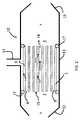
図1は、接線方向フィルター構造体であり、これは、主軸(X)を有する円筒形状の支持体1、フィルター処理される液体が循環する方向に従って、上流面2、及び下流面3、を有する。主軸(X)に平行に、複数の流路4が、支持体の内部部分8に形成されており、多孔性の内部壁5によって、互いに分離されている。周縁壁7が、支持体の内部部分8に位置する流路を、外部から分離する。流路4は、フィルター処理される液体が循環する方向において、上流面及び下流面において、開かれている。流路4は、その内部表面において、(明確さのために図1では1つの流路のみについて描写されている)メンブレン6によって、覆われている。作動時には、液体が下流面に送られ、流路4を介して構造体を通過する。接線方向フィルター処理の原理によれば、液体の一部が構造体1の多孔性の壁5を通過し、壁に適用されているメンブレン6を介して、フィルター処理される。フィルター処理された液体(ろ液)は、周縁壁7を通過した後に、フィルターの周縁において、それ自体知られている(図1には図示されていない)回収手段、例えば、国際公開第2017/085551号に記載されているタイプの回収手段を介して、回収される。流路に残っている液体(残留分)は、構造体の上流側において除去され、例えば、同一タイプの他のフィルター処理ユニットの方に送られる。 FIG. 1 is a tangential filter structure, which has a
一般的な法則として、図2で見られるように、上述のフィルター構造体は、上述のフィルター構造体の周りを封止する包囲体11を含むフィルター処理装置10に、挿入される。この包囲体は、特には、図2で見られるように、フィルター処理される液体15を導入するための、上述のフィルター構造体の上流面において流路と流体的に接続している、手段12、フィルター構造体の周縁において透過液9を除去するための、上述のフィルター構造体の周縁壁に流体的に接続している、手段13、及び、上述のフィルター構造体の下流面における残留分又は濃縮物14を除去するための、手段16、並びに、封止材17を、有している。 As a general rule, as seen in FIG. 2, the above-mentioned filter structure is inserted into a
図3は、流入流路及び流出流路が円状の断面であるフィルター処理フィルターの上流面の正面図である。図3は、上述のパラメータeint(流路間の内部壁の最小厚み)、eext(フィルターの周縁壁の最小厚み)、tm及びDhを、描写している。FIG. 3 is a front view of the upstream surface of the filtered filter having a circular cross section of the inflow channel and the outflow channel. FIG. 3 depicts the parameters eint (minimum thickness of the inner wall between the flow paths), eext (minimum thickness of the peripheral wall of the filter),tm andDh described above.
本発明を、添付の図1~図5とともに、下記の非制限的な例示を用いて、説明する。 The present invention will be described with reference to FIGS. 1-5 with reference to the following non-limiting examples.
≪A:第1の一連の例≫
本発明に係る構造体(実施例1)及び比較構造体(C11~C16)の第1の一連の例を、下記の方法に従って、準備した。<< A: First series of examples >>
A first series of examples of the structure (Example 1) and the comparative structure (C11 to C16) according to the present invention were prepared according to the following method.
<実施例(発明)>
支持体を、当業者に既知の技術に従って、炭化ケイ素のハニカムを形成することによって、製造した。これを行うために、下記を、混合器において混合した:
- 約60μmのメジアン直径を有する粒子の第1粉末75重量%、及び、約2.0μmのメジアン直径を有する粒子の第2粉末25重量%を含有する、純度98%超の炭化ケイ素の粒子の2つの粉末の混合物3000g、
- セルロース誘導体タイプの有機バインダー300g。<Example (invention)>
The support was manufactured by forming a honeycomb of silicon carbide according to techniques known to those of skill in the art. To do this, the following were mixed in a mixer:
-A particle of silicon carbide having a purity of more than 98%, which contains 75% by weight of a first powder of particles having a median diameter of about 60 μm and 25% by weight of a second powder of particles having a median diameter of about 2.0 μm. 3000 g of a mixture of two powders,
-300 g of cellulose derivative type organic binder.
SiC及び有機バインダーの質量に対して約25重量%の水を添加し、混合物を混合して、40%の多孔度を有する支持体を得るための押出を可能にする可塑性を有する、均一なペーストを、形成した。 A uniform paste with plasticity that allows extrusion to add about 25% by weight water to the mass of SiC and organic binder and mix the mixture to obtain a support with 40% porosity. Was formed.
ダイを用いてこのペーストから支持体を押出し、それによって、51mmの直径及び300mmの長さを有する円筒状の未加工一体型ブロックを得た。これの内部部分は、円状断面の複数の流路を有していた。ダイの形状は、図4のような、3mmの水力学的直径を有する円状断面の流路、及び1200μmの最小厚みを有する内部壁を得るために適していた。 A support was extruded from this paste using a die, thereby obtaining a cylindrical raw integrated block with a diameter of 51 mm and a length of 300 mm. The inner part of this had multiple channels with a circular cross section. The shape of the die was suitable for obtaining a circular cross-section channel with a hydraulic diameter of 3 mm and an internal wall with a minimum thickness of 1200 μm, as shown in FIG.
得られた未加工支持体を、乾燥し、それによって、化学的に結合していない水の含有量を、1重量%未満にし、そして、アルゴン下で、2100℃の温度にまで焼成し、この温度を5時間にわたって維持した。得られた支持体は、水銀ポロシメトリーによって測定したときに、開放細孔率40%、及び約25μmのメジアン細孔直径を有していた。 The resulting raw support was dried, thereby reducing the content of chemically unbonded water to less than 1% by weight and firing under argon to a temperature of 2100 ° C. The temperature was maintained for 5 hours. The obtained support had an open pore ratio of 40% and a median pore diameter of about 25 μm as measured by mercury porosymmetry.
そして、フィルター処理メンブレンを、流路の内部表面に適用した。メンブレンは、スラリーコーティングによって適用した。これを行うために、スラリーから、メンブレンキーイングプライマーを、まず形成した。このスラリーの無機配合は、約20μmのメジアン直径D50を有する黒色SiCの粒子の粉末50重量%、及び、脱イオン水50%を含有していた。 Then, the filtered membrane was applied to the inner surface of the flow path. Membranes were applied by slurry coating. To do this, membrane keying primers were first formed from the slurry. The inorganic composition of this slurry contained 50% by weight of powder of black SiC particles having a median diameter D50 of about 20 μm and 50% of deionized water.
そして、約1μmのメジアン直径を有するSiCの粒子50重量%及び脱イオン水50%を含有するスラリーから、分離層を、プライマー層に適用した。スラリーの粘度は、規格DINC33-53019-1:2008に従って22℃においてせん断勾配1s-1で計測したときのスラリーの粘度を、当業者に既知の添加剤を用いて、0.1Pa.sに調節した。 Then, a separation layer was applied to the primer layer from the slurry containing 50% by weight of SiC particles having a median diameter of about 1 μm and 50% of deionized water. The viscosity of the slurry was 0.1 Pa. The viscosity of the slurry when measured at 22 ° C. with a shear gradient of 1s-1 according to the standard DINC33-53019-1: 2008 using an additive known to those skilled in the art. Adjusted to s.
プライマー及びメンブレンは、同じ方法で適用した。スラリーは、20回転/分で攪拌しつつタンクに導入された。攪拌を維持したまま、わずかな吸引下、典型的には25mbarにおける空気除去段階の後に、貯留容器を約+1barのわずかな過圧下で配置し、それにより、支持体の内部が、底部から上部にまでコーティングされうるようにした。この操作は、300mmの長さの支持体に関して、ほんの数秒しか要しない。スラリーは、フィルター要素の流路の内部壁をコーティングし、そして、余分は、堆積の直後に重力下で除去した。 Primers and membranes were applied in the same way. The slurry was introduced into the tank with stirring at 20 rpm. While maintaining agitation, the storage vessel is placed under a slight suction, typically after an air removal step at 25 mbar, under a slight overpressure of about +1 bar, whereby the interior of the support is placed from bottom to top. Allowed to be coated. This operation takes only a few seconds for a support with a length of 300 mm. The slurry coated the inner wall of the flow path of the filter element, and the excess was removed under gravity immediately after deposition.
そして、コーティングされた支持体を、30分間にわたって周囲雰囲気で乾燥させ、そして、60℃で30時間にわたって乾燥させた。そして、このようにして乾燥させたコーティングされた支持体を、4時間にわたってアルゴンの周囲雰囲気下で1400℃の温度で焼結させ、それによって、250nmのメジアン細孔直径を有する多孔度40%のメンブレンを得た。 The coated support was then dried in the ambient atmosphere for 30 minutes and then dried at 60 ° C. for 30 hours. The coated support thus dried is then sintered at a temperature of 1400 ° C. under an ambient atmosphere of argon for 4 hours, thereby having a median pore diameter of 250 nm and a porosity of 40%. A membrane was obtained.
このようにして得られたフィルター構造体は、添付の表1に報告する特徴を有していた。その直径φfは、本発明に係る関係式(1)を満たす。The filter structure thus obtained had the characteristics reported in Attached Table 1. The diameter φf satisfies the relational expression (1) according to the present invention.
<比較例C11及びC12>
本発明に係る実施例とは異なり、ダイを修正して、比較的小さい直径の支持体を得て、実施例1に係るフィルターと同一の直径φfを有する複数要素フィルターを、形成した。他の構造体パラメータは、すべて、そのままであった。3つのユニットを、国際公開第2017/085551号に記載の原則に従ってアセンブルして、比較例C11に係るフィルターを構成した;4つのユニットを、国際公開第2017/085551号に記載の原則に従ってアセンブルして、比較例C12に係るフィルターを構成した。アセンブルされたフィルターにおけるそれぞれのユニットの間の間隔は、3mmであった。<Comparative Examples C11 and C12>
Unlike the examples according to the present invention, the die was modified to obtain a support having a relatively small diameter to form a multi-element filter having the same diameter φf as the filter according to the first embodiment. All other structure parameters remained unchanged. Three units were assembled according to the principles described in WO 2017/085551 to form a filter according to Comparative Example C11; four units were assembled according to the principles described in WO 2017/085551. Therefore, the filter according to Comparative Example C12 was constructed. The spacing between each unit in the assembled filter was 3 mm.
<比較例C13及びC14>
支持体及びメンブレンを、本発明に係る例と同様にして製造した。本発明に係る実施例1とは異なり、ダイを修正して、それぞれ40mm及び62mmの直径φfを有する例C13及びC14に係る一体型支持体を得た。他の構造体パラメータは、すべてそのままであった。したがって、これらの2つの構造体の直径は、本願において本発明に係る式(1)によって定義されている範囲の、それぞれ下限及び上限の、外にある。<Comparative Examples C13 and C14>
The support and the membrane were manufactured in the same manner as in the example according to the present invention. Unlike Example 1 according to the present invention, the dies were modified to obtain integrated supports according to Examples C13 and C14 having diametersφf of 40 mm and 62 mm, respectively. All other structure parameters remained unchanged. Therefore, the diameters of these two structures are outside the lower and upper limits of the range defined by equation (1) according to the present invention, respectively.
<比較例C15及びC16>
比較例C15及びC16に係るフィルターは、比較例C14と同一の直径を有しているが、国際公開第2017/085551号に記載の原則に従って、ユニットをアセンブルし、それによって、C14に係る一体型フィルター構造体と同一の直径φfを有する複数要素フィルターを作り出すことによって、形成された。他の構造体パラメータは、この例に対して変更しないままであった。アセンブルされたフィルターにおけるそれぞれのユニットの間の間隔は、3mmであった。<Comparative Examples C15 and C16>
The filters according to Comparative Examples C15 and C16 have the same diameter as Comparative Example C14, but the units are assembled according to the principle described in International Publication No. 2017/0855551, whereby the integrated type according to C14. It was formed by creating a multi-element filter with the same diameter φf as the filter structure. Other structure parameters remained unchanged for this example. The spacing between each unit in the assembled filter was 3 mm.
実施例1及びC11~C16に関して得られた全てのデータ及び結果を、下記の表1に報告する。 All data and results obtained for Example 1 and C11-C16 are reported in Table 1 below.
<B:第2の一連の例>
この第2の一連の例では、本発明に係る構造体(実施例2)及び比較構造体(C21~C26)を、下記に記載のものと同一の方法及び原則を用いて、準備した。この第2の一連の例では、支持体の透過率Ksが変更されていた。<B: Second series of examples>
In this second series of examples, the structures (Example 2) and comparative structures (C21-C26) according to the present invention were prepared using the same methods and principles as those described below. In this second series of examples, the transmittanceKs of the support was changed.
<本発明に係る実施例2>
実施例1とは異なる、透過率Ksに関する別の値を得るために、この第2の一連の例では、支持体を、約11μmのメジアン直径を有する粒子の第1粉末70重量%、及び、約0.5μmのメジアン直径を有する粒子の第2粉末30重量%を含有する、純度98%超の炭化ケイ素の粒子の2つの粉末の混合物から、製造した。<Example 2 according to the present invention>
In order to obtain a different value for permeabilityKs , which is different from Example 1, in this second series of examples, the support is a first powder of 70% by weight of particles having a median diameter of about 11 μm, and Made from a mixture of two powders of silicon carbide particles over 98% pure, containing 30% by weight of a second powder of particles having a median diameter of about 0.5 μm.
そして、得られた未加工支持体を乾燥させて、化学的に結合していない水の含有量を、1重量%未満にし、そして、アルゴン下で2150℃の温度にまで焼成し、この温度を5時間にわたって維持した。得られた支持体は、水銀ポロシメトリーで計測したときに、40%の開放細孔率、及び、約15μmのメジアン細孔直径を有していた。 The resulting raw support is then dried to reduce the content of chemically unbonded water to less than 1% by weight and then fired under argon to a temperature of 2150 ° C. to this temperature. Maintained for 5 hours. The obtained support had a 40% open pore ratio and a median pore diameter of about 15 μm as measured by mercury porosymmetry.
このようにして得られた支持体の透過率は、表2で報告されるように、第1の一連の例において計測されたものよりも、低かった。そして、例示のために用いられた方法と同一の手順を使用して、実施例1に係る構造体と同一のプライマーとともに、同一のメンブレンを、適用した。 The transmittance of the support thus obtained was lower than that measured in the first series of examples, as reported in Table 2. Then, using the same procedure as the method used for the illustration, the same membrane was applied together with the same primer as the structure according to Example 1.
<比較例C21~C26>
比較例C21~C26は、それぞれ、C11~C16に対応しており、これらの例では、実施例2に係る比較的低い透過率の支持体を用いてフィルターを形成した点が、異なっている。<Comparative Examples C21 to C26>
Comparative Examples C21 to C26 correspond to C11 to C16, respectively, and these examples differ in that the filter is formed by using the support having a relatively low transmittance according to Example 2.
得られた全てのデータ及び結果を、下記の表2に報告する。 All data and results obtained are reported in Table 2 below.
<テスト及び結果の表>
これらの一体型又は複数要素のフィルター構造体のそれぞれに関して、Φ/Φmaxを決定した。Φは、対象のフィルター構造体の特性流であり、Φmaxは、第1の一連の例に関して本発明に係る実施例1に係るフィルター構造体について計測した流れ、又は、第2の一連の例に関して本発明に係る実施例2に係るフィルター構造体について計測した流れであり、100%の効率が与えられている。フィルターの特性流は、下記の方法を用いて評価した:25℃の温度において、脱塩水から形成される液体を、評価対象のフィルターに、0.5barのメンブレン間圧力、及び2m/sの流路方向流速で、供給する。透過液を、フィルターの周縁で回収する。フィルターの特性流の計測を、20時間のフィルター処理の後で、L/h/m/barで表す。得られた結果を、このようにして得られたフィルターの関連する寸法特性と一緒に、下記の表1にまとめる。<Table of tests and results>
Φ / Φmax was determined for each of these integrated or multi-element filter structures. Φ is the characteristic flow of the target filter structure, and Φmax is the flow measured for the filter structure according to the first embodiment of the present invention with respect to the first series of examples, or the second series of examples. It is a flow measured about the filter structure which concerns on Example 2 which concerns on this invention, and the efficiency of 100% is given. The characteristic flow of the filter was evaluated using the following method: at a temperature of 25 ° C., a liquid formed from desalinated water was applied to the filter under evaluation at a pressure of 0.5 bar between membranes and a flow of 2 m / s. It is supplied at the flow velocity in the road direction. The permeate is collected at the periphery of the filter. The measurement of the characteristic flow of the filter is expressed in L / h / m / bar after 20 hours of filtering. The results obtained are summarized in Table 1 below, along with the relevant dimensional characteristics of the filters thus obtained.
<結果の解釈>
(第1の一連の例(本発明に係る実施例1、及びC11~C16)について)
表1に記載の流れの比によって示されているように、例C11及びC12に係る複数要素のフィルターは、本発明に係る実施例1に係る一体型構造体よりも劣るフィルター処理能力を有する。<Interpretation of results>
(Regarding the first series of examples (Example 1 and C11 to C16 according to the present invention))
As shown by the flow ratios shown in Table 1, the multi-element filters according to Examples C11 and C12 have inferior filtering capacity to the integrated structure according to Example 1 according to the present invention.
例C13に係る一体型フィルター構造体は、本発明に従った直径を有しておらず、参照構造体と比較して大幅に劣る流れを示す。 The integrated filter structure according to Example C13 does not have a diameter according to the present invention and shows a significantly inferior flow as compared to the reference structure.
例C14~C16の比較が明らかにすることができるのは、支持体及びフィルターメンブレンの構造特性の組み合わせを考慮している、本発明に従って選択された一体型のフィルター構造体が、最適化されている流れ及びフィルター処理能力を示す、ということである。特に、複数のフィルターユニット(例C15及びC16)をアセンブルすることによって得られるフィルターに従って計測される流れは、同一の直径を有する一体型の構造体(例C14)に関する流れよりも、良好な性能を示す。このような場合には、複数要素のフィルターは、実施が比較的複雑ではあるが、比較的良好に機能する。 The comparison of Examples C14 to C16 can be made clear by optimizing the integrated filter structure selected according to the present invention, taking into account the combination of structural properties of the support and filter membrane. It indicates the current flow and filtering capacity. In particular, the flow measured according to the filter obtained by assembling multiple filter units (eg C15 and C16) outperforms the flow for an integral structure with the same diameter (eg C14). show. In such cases, the multi-element filter works relatively well, although it is relatively complex to implement.
実施例2が示すのは、本発明を適用することによって、比較的低い支持体透過率Ksは、一体型フィルター構造体の比較的小さい直径φfを要求する、ということである。Example 2 shows that by applying the present invention, a relatively low support permeabilityKs requires a relatively small diameterφf of the integrated filter structure.
第1の一連の例と同様に、本発明に係る同一の式(1)を適用することによって、支持体及びメンブレンの構造体パラメータに従って、フィルターの直径を最適化することができることが、見いだされる。 Similar to the first series of examples, it is found that by applying the same equation (1) according to the present invention, the diameter of the filter can be optimized according to the structural parameters of the support and the membrane. ..
同様に本願の会社の出願に係るものである国際公開第2015/177476号(D1)及び国際公開第2016/097661号(D2)で記載されている種々のフィルターも、評価した。テスト及び計算の結果を、下記の表3に報告する。これらの例で記載される構造体の直径の値は、最適ではなく、かつ、特には本願の特許請求の範囲に記載の本発明の要件を満たしていないことが、分かるであろう。 Similarly, the various filters described in International Publication No. 2015/177476 (D1) and International Publication No. 2016/097661 (D2) relating to the application of the company of the present application were also evaluated. The results of the tests and calculations are reported in Table 3 below. It will be found that the diameter values of the structures described in these examples are not optimal and, in particular, do not meet the requirements of the invention described in the claims of the present application.


<態様1><
下記を有する、液体をフィルター処理するための一体型のメンブレンタイプのフィルター構造体: An integrated membrane-type filter structure for filtering liquids with:
- 透過率K -Transmittance Kssの多孔性無機材料から形成されている支持体、前記支持体は、主軸、上流基部、下流基部、内部部分を画定している周縁壁を有する、チューブ状の全体的な形状を有している、A support made of a porous inorganic material of the above, said support having a tubular overall shape with a peripheral wall defining a main shaft, an upstream base, a downstream base, and an internal portion. ,
- 前記支持体の前記内部部分に形成されている、前記支持体の前記主軸に平行な、複数の流路、前記流路は、多孔性無機材料でできている内部壁によって、互いに分離されている、 -A plurality of flow paths parallel to the main axis of the support, which are formed in the internal portion of the support, are separated from each other by an internal wall made of a porous inorganic material. Yes,
- すべての前記流路は、前記液体が循環する方向において、それらの上流側端部又は下流側端部において開かれており、 -All said channels are open at their upstream or downstream ends in the direction in which the liquid circulates.
- フィルター処理された液体は、前記周縁壁を介して除去され、 -The filtered liquid is removed through the peripheral wall and
- 透過率K -Transmittance Kmm及び平均厚みtAnd average thickness tmmのメンブレンが、前記流路の内部表面を覆っており、Membrane covers the inner surface of the flow path.
前記フィルター構造は、その外部水力学的直径φ The filter structure has an external hydraulic diameter φ.ffが、下記の関係(1)を満たすことを特徴とする:Is characterized by satisfying the following relationship (1):
φ φff=α×[A+B×log= Α × [A + B × log1010(K(Kss×t× tmm/K/ Kmm)] (1))] (1)
ここで、αは、0.85と1.15との間の係数であり、かつ、 Here, α is a coefficient between 0.85 and 1.15, and
D Dhhは、前記流路の平均の水力学的直径であり、Is the average hydraulic diameter of the flow path.
e eintintは、前記流路の間の前記内部壁の最小厚みであり、Is the minimum thickness of the internal wall between the flow paths.
e eextextは、フィルターの前記周縁壁の最小厚みであり、Is the minimum thickness of the peripheral wall of the filter.
t tmm、φ, Φff、e, Eintint、e, Eextext、及びD, And Dhhは、メートルで表され、かつKIs expressed in meters and Kss及びKAnd Kmmは、mIs m22で表される。It is represented by.
<態様2><
比K Ratio Kss×t× tmm/K/ Kmmが、0.01mと10mとの間である、態様1に記載のフィルター構造体。The filter structure according to
<態様3><
前記支持体の前記外部水力学的直径φ The external hydraulic diameter φ of the supportffが、30mmと100mmとの間、好ましくは50mm超80mm未満である、態様1又は2に記載のフィルター構造体。The filter structure according to
<態様4><
前記流路の平均の水力学的直径d Average hydraulic diameter d of the flow pathhhが、0.5mmと7mmとの間、好ましくは1mmと5mmとの間、より好ましくは1.5mmと3.5mmとの間である、態様1~3のいずれか一項に記載のフィルター構造体。The filter structure according to any one of
<態様5><
前記支持体の前記内部壁の最小厚みe Minimum thickness of the inner wall of the support eintintが、0.3mmと3mmとの間、好ましくは0.7mmと2mmとの間である、態様1~4のいずれか一項に記載のフィルター構造体。The filter structure according to any one of
<態様6><
前記支持体が、正方形、六角形、又は円形の基部、好ましくは円形の基部を有することを特徴とする、態様1~5のいずれか一項に記載のフィルター構造体。 The filter structure according to any one of
<態様7><Aspect 7>
すべての前記流路が、同一の水力学的直径を有することを特徴とする、態様1~6のいずれか一項に記載のフィルター構造体。 The filter structure according to any one of
<態様8><
少なくとも2つの前記流路が、異なる水力学的直径を有することを特徴とする、態様1~7のいずれか一項に記載のフィルター構造体。 The filter structure according to any one of
<態様9><Aspect 9>
前記フィルターの前記周縁壁の最小厚みe Minimum thickness of the peripheral wall of the filter eextextが、0.5mmと4mmとの間、好ましくは1mmと2mmとの間であることを特徴とする、態様1~8のいずれか一項に記載のフィルター構造体。The filter structure according to any one of
<態様10><
前記支持体の透過率K Transmittance K of the supportssが、好ましくは、1.0×10However, preferably 1.0 × 10⁻¹⁴-14と1.0×10And 1.0 × 10⁻¹¹-11との間であることを特徴とする、態様1~9のいずれか一項に記載のフィルター構造体。The filter structure according to any one of
<態様11><
前記メンブレンの透過率K Transmittance K of the membranemmが、好ましくは、1.0×10However, preferably 1.0 × 10⁻¹⁹-19と1.0×10And 1.0 × 10⁻¹⁴-14との間であることを特徴とする、態様1~10のいずれか一項に記載のフィルター構造体。The filter structure according to any one of
<態様12><
前記メンブレンの平均厚みt Average thickness t of the membranemmが、0.1μm~300μm、好ましくは10μm~70μmの範囲である、ことを特徴とする、態様1~11のいずれか一項に記載のフィルター構造体。The filter structure according to any one of
<態様13><
前記メンブレンが、10%と70%との間、好ましくは30%と50%との間である開放細孔率を有することを特徴とする、態様1~12のいずれか一項に記載のフィルター構造体。 The filter according to any one of aspects 1-12, wherein the membrane has an open pore ratio between 10% and 70%, preferably between 30% and 50%. Structure.
<態様14><
前記支持体の細孔のメジアン直径が、20μmと50μmとの間であることを特徴とする、態様1~13のいずれか一項に記載のフィルター構造体。 The filter structure according to any one of
<態様15><
前記流路が、円形又は多角形の断面を有し、特には、正方形、六角形、又は八角形の断面、特には、正方形の断面、を有することを特徴とする、態様1~14のいずれか一項に記載のフィルター構造体。 Any of aspects 1-14, wherein the flow path has a circular or polygonal cross section, particularly a square, hexagonal, or octagonal cross section, particularly a square cross section. The filter structure according to
<態様16><
下記を有する、フィルター処理装置: Filtering device with:
- 前記フィルター構造体、 -The filter structure,
- 前記フィルター構造体の周りを封止する包囲体、この包囲体は、下記を有する: -A siege that seals around the filter structure, the siege having:
- フィルター処理される液体を導入するための、前記フィルター構造体の前記上流面において前記流路に流体的に接続している、手段、 -Means, which are fluidly connected to the flow path on the upstream surface of the filter structure for introducing the liquid to be filtered.
- 前記フィルター構造体の周縁において透過液を除去するための、前記フィルター構造体の前記周縁壁に流体的に接続している、手段、 -Means, which are fluidly connected to the peripheral wall of the filter structure, for removing permeate at the peripheral edge of the filter structure.
- 前記フィルター構造体の前記下流面における残留分又は濃縮物を除去するための、手段。 -Means for removing residues or concentrates on the downstream surface of the filter structure.
<態様17><
態様1~15のいずれか一項に記載のフィルター構造体、又は、態様16に記載のフィルター処理装置の、液体の精製及び/又は分離のための、化学、医薬、食品、若しくは農食品の産業における、バイオリアクターにおける、又は、シェールからの石油若しくはガスの抽出における、使用。 The chemical, pharmaceutical, food, or agricultural food industry for the purification and / or separation of liquids of the filter structure according to any one of
Claims (17)
Translated fromJapanese- 透過率Ksの多孔性無機材料から形成されている支持体、前記支持体は、主軸、上流基部、下流基部、内部部分を画定している周縁壁を有する、チューブ状の全体的な形状を有している、
- 前記支持体の前記内部部分に形成されている、前記支持体の前記主軸に平行な、複数の流路、前記流路は、多孔性無機材料でできている内部壁によって、互いに分離されている、
- すべての前記流路は、前記液体が循環する方向において、それらの上流側端部又は下流側端部において開かれており、
- フィルター処理された液体は、前記周縁壁を介して除去され、
- 透過率Km及び平均厚みtmのメンブレンが、前記流路の内部表面を覆っており、
前記支持体の透過率Ks及び前記メンブレンの透過率Kmは、K=(PO3×D502)/[180×(1-PO)2]によって定義され、POは、開放細孔率であり、D50は、細孔のメジアン直径であり、
前記支持体のPO及びD50は、規格ISO15901-1.2005パート1に従って、水銀ポロシメトリーによって決定され、前記メンブレンの開放細孔率及びD50は、走査型電子顕微鏡を用いて決定され、
前記フィルター構造体は、その外部水力学的直径φfが、下記の関係(1)を満たすことを特徴とする:
φf=α×[A+B×log10(Ks×tm/Km)] (1)
ここで、αは、0.85と1.15との間の係数であり、かつ、

Dhは、前記流路の平均の水力学的直径であり、
eintは、前記流路の間の前記内部壁の最小厚みであり、
eextは、フィルターの前記周縁壁の最小厚みであり、
tm、φf、eint、eext、及びDhは、メートルで表され、かつKs及びKmは、m2で表される。An integrated membrane-type filter structure for filtering liquids with:
-A support made of a porous inorganic material with a transmittance of Ks , said support having a tubular overall shape with a peripheral wall defining a main shaft, an upstream base, a downstream base, and an internal portion. have,
-A plurality of flow paths parallel to the main axis of the support, which are formed in the internal portion of the support, are separated from each other by an internal wall made of a porous inorganic material. Yes,
-All said channels are open at their upstream or downstream ends in the direction in which the liquid circulates.
-The filtered liquid is removed through the peripheral wall and
-A membrane having a transmittance of Km and an average thickness of tm covers the inner surface of the flow path.
The transmittance Ks of the support and the transmittance Km of themembrane are defined byK = (PO3× D502 ) / [180 × (1-PO)2], where PO is the open pore ratio. AndD50is the median diameter of the pores,
The PO and D50 of the supportweredetermined by mercury porosimetry according to standard ISO1591-1.2005 Part 1, and the open pore ratio and D50 of the membrane weredeterminedusing a scanning electron microscope.
The filterstructure is characterized in that its external hydraulic diameter φf satisfies the following relationship (1):
φf = α × [A + B × log10 (Ks × tm / Km )] (1)
Here, α is a coefficient between 0.85 and 1.15, and
Dh is the average hydraulic diameter of the flow path.
eint is the minimum thickness of the internal wall between the flow paths.
eext is the minimum thickness of the peripheral wall of the filter.
tm , φf , eint , eext , and Dh are expressed in meters, and Ks and Km are expressed in m2 .
-請求項1~15のいずれか一項に記載の前記フィルター構造体、
- 前記フィルター構造体の周りを封止する包囲体、この包囲体は、下記を有する:
- フィルター処理される液体を導入するための、前記フィルター構造体の前記上流面において前記流路に流体的に接続している、手段、
- 前記フィルター構造体の周縁において透過液を除去するための、前記フィルター構造体の前記周縁壁に流体的に接続している、手段、
- 前記フィルター構造体の前記下流面における残留分又は濃縮物を除去するための、手段。Filtering device with:
-The filter structureaccording to any one of claims 1 to 15 .
-A siege that seals around the filter structure, the siege having:
-Means, which are fluidly connected to the flow path on the upstream surface of the filter structure for introducing the liquid to be filtered.
-Means, which are fluidly connected to the peripheral wall of the filter structure, for removing permeate at the peripheral edge of the filter structure.
-Means for removing residues or concentrates on the downstream surface of the filter structure.
Applications Claiming Priority (3)
| Application Number | Priority Date | Filing Date | Title |
|---|---|---|---|
| FR1761432 | 2017-11-30 | ||
| FR1761432AFR3074060B1 (en) | 2017-11-30 | 2017-11-30 | MONOLITHIC MEMBRANE FILTERING STRUCTURE |
| PCT/FR2018/053044WO2019106306A1 (en) | 2017-11-30 | 2018-11-29 | Monolithic membrane filtration structure |
Publications (2)
| Publication Number | Publication Date |
|---|---|
| JP2021504128A JP2021504128A (en) | 2021-02-15 |
| JP7084997B2true JP7084997B2 (en) | 2022-06-15 |
Family
ID=61521633
Family Applications (1)
| Application Number | Title | Priority Date | Filing Date |
|---|---|---|---|
| JP2020529634AActiveJP7084997B2 (en) | 2017-11-30 | 2018-11-29 | Integrated membrane filter structure |
Country Status (7)
| Country | Link |
|---|---|
| US (1) | US11628404B2 (en) |
| EP (1) | EP3717106B1 (en) |
| JP (1) | JP7084997B2 (en) |
| CN (1) | CN111372672B (en) |
| ES (1) | ES2989871T3 (en) |
| FR (1) | FR3074060B1 (en) |
| WO (1) | WO2019106306A1 (en) |
Citations (4)
| Publication number | Priority date | Publication date | Assignee | Title |
|---|---|---|---|---|
| WO2015177476A1 (en) | 2014-05-22 | 2015-11-26 | Saint-Gobain Centre De Recherches Et D'etudes Europeen | Tangential filter with a supporting element including a set of channels |
| WO2016097661A1 (en) | 2014-12-18 | 2016-06-23 | Saint-Gobain Centre De Recherches Et D'etudes Europeen | Filters comprising sic membranes incorporating nitrogen |
| WO2017103473A1 (en) | 2015-12-18 | 2017-06-22 | Saint-Gobain Centre De Recherches Et D'etudes Europeen | Monolithic filter |
| JP2018505770A (en) | 2014-12-18 | 2018-03-01 | サン−ゴバン サントル ドゥ ルシェルシェ エ デトゥードゥ ユーロペン | SiC-nitride or SiC-oxynitride composite membrane filter |
Family Cites Families (12)
| Publication number | Priority date | Publication date | Assignee | Title |
|---|---|---|---|---|
| US4069157A (en) | 1975-11-20 | 1978-01-17 | E. I. Du Pont De Nemours And Company | Ultrafiltration device |
| US4781831A (en) | 1986-12-19 | 1988-11-01 | Goldsmith Robert L | Cross-flow filtration device with filtrate flow conduits and method of forming same |
| DE4324347A1 (en) | 1992-07-23 | 1994-01-27 | Noritake Co Ltd | Mass produced monolithic ceramic filter - has honeycomb structure with partition wall section, useful for micro and ultra filtration and reverse osmosis |
| US6077436A (en) | 1997-01-06 | 2000-06-20 | Corning Incorporated | Device for altering a feed stock and method for using same |
| JP4298116B2 (en) | 2000-02-23 | 2009-07-15 | 日本碍子株式会社 | Manufacturing method and manufacturing apparatus for honeycomb structure with slit |
| JP4195824B2 (en) | 2003-03-10 | 2008-12-17 | メタウォーター株式会社 | Filtration method |
| JP4358538B2 (en) | 2003-03-17 | 2009-11-04 | 日本碍子株式会社 | Ceramic filter |
| US7686959B2 (en) | 2004-05-05 | 2010-03-30 | Biotage Ab | Control system and method for flash separation |
| US7169213B2 (en)* | 2004-10-29 | 2007-01-30 | Corning Incorporated | Multi-channel cross-flow porous device |
| DE102009001383A1 (en)* | 2008-12-17 | 2010-06-24 | Robert Bosch Gmbh | Liquid filter and filter system |
| FR2970422B1 (en)* | 2011-01-13 | 2013-02-08 | Technologies Avancees Et Membranes Ind | NEW GEOMETRY OF FILTRATION ELEMENTS |
| CA3005698A1 (en) | 2015-11-20 | 2017-05-26 | 1934612 Ontario Inc. | Multi-layered ceramic membrane and method of making the same |
- 2017
- 2017-11-30FRFR1761432Apatent/FR3074060B1/enactiveActive
- 2018
- 2018-11-29EPEP18827206.6Apatent/EP3717106B1/enactiveActive
- 2018-11-29CNCN201880077565.6Apatent/CN111372672B/enactiveActive
- 2018-11-29WOPCT/FR2018/053044patent/WO2019106306A1/ennot_activeCeased
- 2018-11-29USUS16/767,422patent/US11628404B2/enactiveActive
- 2018-11-29JPJP2020529634Apatent/JP7084997B2/enactiveActive
- 2018-11-29ESES18827206Tpatent/ES2989871T3/enactiveActive
Patent Citations (5)
| Publication number | Priority date | Publication date | Assignee | Title |
|---|---|---|---|---|
| WO2015177476A1 (en) | 2014-05-22 | 2015-11-26 | Saint-Gobain Centre De Recherches Et D'etudes Europeen | Tangential filter with a supporting element including a set of channels |
| JP2017521235A (en) | 2014-05-22 | 2017-08-03 | サン−ゴバン サントル ドゥ ルシェルシェ エ デトゥードゥ ユーロペン | Tangential filter having a support element comprising a set of channels |
| WO2016097661A1 (en) | 2014-12-18 | 2016-06-23 | Saint-Gobain Centre De Recherches Et D'etudes Europeen | Filters comprising sic membranes incorporating nitrogen |
| JP2018505770A (en) | 2014-12-18 | 2018-03-01 | サン−ゴバン サントル ドゥ ルシェルシェ エ デトゥードゥ ユーロペン | SiC-nitride or SiC-oxynitride composite membrane filter |
| WO2017103473A1 (en) | 2015-12-18 | 2017-06-22 | Saint-Gobain Centre De Recherches Et D'etudes Europeen | Monolithic filter |
Also Published As
| Publication number | Publication date |
|---|---|
| WO2019106306A1 (en) | 2019-06-06 |
| CN111372672B (en) | 2022-10-18 |
| US11628404B2 (en) | 2023-04-18 |
| FR3074060B1 (en) | 2023-04-28 |
| ES2989871T3 (en) | 2024-11-28 |
| CN111372672A (en) | 2020-07-03 |
| FR3074060A1 (en) | 2019-05-31 |
| JP2021504128A (en) | 2021-02-15 |
| EP3717106C0 (en) | 2024-07-31 |
| EP3717106B1 (en) | 2024-07-31 |
| US20200384419A1 (en) | 2020-12-10 |
| EP3717106A1 (en) | 2020-10-07 |
Similar Documents
| Publication | Publication Date | Title |
|---|---|---|
| KR20170095330A (en) | Filters comprising sic membranes incorporating nitrogen | |
| US20220274070A1 (en) | Filter comprising a silicone carbide separator layer | |
| KR102358966B1 (en) | Tangential filter with a supporting element including a set of channels | |
| CN109310953B (en) | Filter comprising a beta-SIC based separation layer | |
| US11033863B2 (en) | Filters comprising oxygen-depleted SiC membranes | |
| US20180304201A1 (en) | Assembled filters for the filtration of liquids | |
| CN1708348A (en) | Membrane for tangential filtration and production method thereof | |
| Vida-Simiti et al. | Characterization of gradual porous ceramic structures obtained by powder sedimentation | |
| JP7084997B2 (en) | Integrated membrane filter structure | |
| JP2018505770A (en) | SiC-nitride or SiC-oxynitride composite membrane filter | |
| US20180361321A1 (en) | Monolithic filter | |
| CN100473443C (en) | Ceramic filter | |
| WO2015151699A1 (en) | Monolithic separation membrane structure | |
| JP7191861B2 (en) | Integral membrane filtration structure | |
| WO2020109731A1 (en) | Dynamic filtering device with porous ceramic silicon carbide plate | |
| JP2004114745A (en) | Filter device | |
| JPH05293342A (en) | Ceramic filter |
Legal Events
| Date | Code | Title | Description |
|---|---|---|---|
| A621 | Written request for application examination | Free format text:JAPANESE INTERMEDIATE CODE: A621 Effective date:20200529 | |
| A131 | Notification of reasons for refusal | Free format text:JAPANESE INTERMEDIATE CODE: A131 Effective date:20210629 | |
| A601 | Written request for extension of time | Free format text:JAPANESE INTERMEDIATE CODE: A601 Effective date:20210927 | |
| A521 | Request for written amendment filed | Free format text:JAPANESE INTERMEDIATE CODE: A523 Effective date:20211223 | |
| TRDD | Decision of grant or rejection written | ||
| A01 | Written decision to grant a patent or to grant a registration (utility model) | Free format text:JAPANESE INTERMEDIATE CODE: A01 Effective date:20220510 | |
| A61 | First payment of annual fees (during grant procedure) | Free format text:JAPANESE INTERMEDIATE CODE: A61 Effective date:20220603 | |
| R150 | Certificate of patent or registration of utility model | Ref document number:7084997 Country of ref document:JP Free format text:JAPANESE INTERMEDIATE CODE: R150 | |
| R250 | Receipt of annual fees | Free format text:JAPANESE INTERMEDIATE CODE: R250 |