JP7083653B2 - Surgical suture device - Google Patents
Surgical suture deviceDownload PDFInfo
- Publication number
- JP7083653B2 JP7083653B2JP2018016954AJP2018016954AJP7083653B2JP 7083653 B2JP7083653 B2JP 7083653B2JP 2018016954 AJP2018016954 AJP 2018016954AJP 2018016954 AJP2018016954 AJP 2018016954AJP 7083653 B2JP7083653 B2JP 7083653B2
- Authority
- JP
- Japan
- Prior art keywords
- shaft
- jaw member
- body portion
- end effector
- longitudinal axis
- Prior art date
- Legal status (The legal status is an assumption and is not a legal conclusion. Google has not performed a legal analysis and makes no representation as to the accuracy of the status listed.)
- Active
Links
- 239000012636effectorSubstances0.000claimsdescription129
- 230000004044responseEffects0.000claimsdescription10
- 238000001356surgical procedureMethods0.000description17
- 210000001061foreheadAnatomy0.000description15
- 230000007246mechanismEffects0.000description10
- 239000004065semiconductorSubstances0.000description10
- 239000003356suture materialSubstances0.000description7
- 238000000034methodMethods0.000description6
- 238000002674endoscopic surgeryMethods0.000description5
- 230000005389magnetismEffects0.000description5
- 206010019909HerniaDiseases0.000description4
- 238000002324minimally invasive surgeryMethods0.000description4
- 230000008439repair processEffects0.000description4
- 239000000463materialSubstances0.000description3
- 239000002184metalSubstances0.000description3
- 210000000056organAnatomy0.000description3
- 230000008569processEffects0.000description3
- 238000002559palpationMethods0.000description2
- 230000000149penetrating effectEffects0.000description2
- 125000002066L-histidyl groupChemical group[H]N1C([H])=NC(C([H])([H])[C@](C(=O)[*])([H])N([H])[H])=C1[H]0.000description1
- 210000003815abdominal wallAnatomy0.000description1
- 230000008901benefitEffects0.000description1
- 210000004534cecumAnatomy0.000description1
- 230000000295complement effectEffects0.000description1
- 238000004590computer programMethods0.000description1
- 238000002405diagnostic procedureMethods0.000description1
- 238000010586diagramMethods0.000description1
- 210000000887faceAnatomy0.000description1
- 230000005307ferromagnetismEffects0.000description1
- 230000006870functionEffects0.000description1
- 210000000232gallbladderAnatomy0.000description1
- 210000000936intestineAnatomy0.000description1
- 210000003734kidneyAnatomy0.000description1
- 230000003278mimic effectEffects0.000description1
- 238000012986modificationMethods0.000description1
- 230000004048modificationEffects0.000description1
- 210000001672ovaryAnatomy0.000description1
- 229920003023plasticPolymers0.000description1
- 239000004033plasticSubstances0.000description1
- 229920000642polymerPolymers0.000description1
- 230000000717retained effectEffects0.000description1
- 229910001285shape-memory alloyInorganic materials0.000description1
- 238000002560therapeutic procedureMethods0.000description1
- 210000004291uterusAnatomy0.000description1
- 238000011179visual inspectionMethods0.000description1
Images


Classifications
- A—HUMAN NECESSITIES
- A61—MEDICAL OR VETERINARY SCIENCE; HYGIENE
- A61B—DIAGNOSIS; SURGERY; IDENTIFICATION
- A61B17/00—Surgical instruments, devices or methods
- A61B17/04—Surgical instruments, devices or methods for suturing wounds; Holders or packages for needles or suture materials
- A61B17/0469—Suturing instruments for use in minimally invasive surgery, e.g. endoscopic surgery
- A—HUMAN NECESSITIES
- A61—MEDICAL OR VETERINARY SCIENCE; HYGIENE
- A61B—DIAGNOSIS; SURGERY; IDENTIFICATION
- A61B17/00—Surgical instruments, devices or methods
- A61B17/04—Surgical instruments, devices or methods for suturing wounds; Holders or packages for needles or suture materials
- A61B17/06—Needles ; Sutures; Needle-suture combinations; Holders or packages for needles or suture materials
- A61B17/06066—Needles, e.g. needle tip configurations
- A—HUMAN NECESSITIES
- A61—MEDICAL OR VETERINARY SCIENCE; HYGIENE
- A61B—DIAGNOSIS; SURGERY; IDENTIFICATION
- A61B17/00—Surgical instruments, devices or methods
- A61B17/04—Surgical instruments, devices or methods for suturing wounds; Holders or packages for needles or suture materials
- A61B17/06—Needles ; Sutures; Needle-suture combinations; Holders or packages for needles or suture materials
- A61B17/062—Needle manipulators
- A61B17/0625—Needle manipulators the needle being specially adapted to interact with the manipulator, e.g. being ridged to snap fit in a hole of the manipulator
- A—HUMAN NECESSITIES
- A61—MEDICAL OR VETERINARY SCIENCE; HYGIENE
- A61B—DIAGNOSIS; SURGERY; IDENTIFICATION
- A61B17/00—Surgical instruments, devices or methods
- A61B17/04—Surgical instruments, devices or methods for suturing wounds; Holders or packages for needles or suture materials
- A61B17/06—Needles ; Sutures; Needle-suture combinations; Holders or packages for needles or suture materials
- A61B17/06066—Needles, e.g. needle tip configurations
- A61B2017/0608—J-shaped
- A—HUMAN NECESSITIES
- A61—MEDICAL OR VETERINARY SCIENCE; HYGIENE
- A61B—DIAGNOSIS; SURGERY; IDENTIFICATION
- A61B17/00—Surgical instruments, devices or methods
- A61B17/28—Surgical forceps
- A61B17/29—Forceps for use in minimally invasive surgery
- A61B2017/2926—Details of heads or jaws
- A61B2017/2927—Details of heads or jaws the angular position of the head being adjustable with respect to the shaft
- A61B2017/2929—Details of heads or jaws the angular position of the head being adjustable with respect to the shaft with a head rotatable about the longitudinal axis of the shaft
- A—HUMAN NECESSITIES
- A61—MEDICAL OR VETERINARY SCIENCE; HYGIENE
- A61B—DIAGNOSIS; SURGERY; IDENTIFICATION
- A61B34/00—Computer-aided surgery; Manipulators or robots specially adapted for use in surgery
- A61B34/30—Surgical robots
Landscapes
- Health & Medical Sciences (AREA)
- Life Sciences & Earth Sciences (AREA)
- Surgery (AREA)
- Heart & Thoracic Surgery (AREA)
- Engineering & Computer Science (AREA)
- Biomedical Technology (AREA)
- Nuclear Medicine, Radiotherapy & Molecular Imaging (AREA)
- Medical Informatics (AREA)
- Molecular Biology (AREA)
- Animal Behavior & Ethology (AREA)
- General Health & Medical Sciences (AREA)
- Public Health (AREA)
- Veterinary Medicine (AREA)
- Surgical Instruments (AREA)
Description
Translated fromJapanese関連出願の相互参照
本出願は、2017年2月23日に出願された、米国仮特許出願第62/462,512号の利益及びそれに対する優先権を主張し、その全体の開示は、参照により本明細書に組み込まれる。Cross-reference to related applications This application claims the benefit and priority of US Provisional Patent Application No. 62 / 462,512 filed on February 23, 2017, the entire disclosure of which is by reference. Incorporated herein.
本開示は、低侵襲の縫合または縫い合わせのための外科用器具に関し、より具体的には、アクセス管を通した縫合または縫い合わせのためのエンドエフェクタに関する。 The present disclosure relates to surgical instruments for minimally invasive sutures or stitches, and more specifically to end effectors for sutures or stitches through access tubes.
関連技術の背景
一般に、内視鏡手術は、例えば、卵巣、子宮、胆嚢、腸、腎臓、または盲腸などの特定器官を検視かつ/または手術するため、体壁を通して切開することを含む。通常、トロカールは、内視鏡手術が実行される切開を作るために利用される。トロカール管またはカニューレ装置は、内視鏡外科用具のためのアクセスを提供するために、腹壁の中に延ばされ、定位置に残される。カメラまたは内視鏡は、通常は海軍の切開に位置している、比較的大きな直径のトロカール管を通して挿入され、目視検査及び体腔の拡大を可能にする。次に、外科医は、追加カニューレに嵌合するように設計されている、鉗子、カッタ、アプリケータなどの、特殊器具の補助で、手術部位で診断及び治療手技を実行することができる。Background of Related Techniques In general, endoscopic surgery involves making an incision through the body wall to inspect and / or operate on a particular organ, such as the ovary, uterus, gallbladder, intestine, kidney, or cecum. Trocars are typically used to make incisions in which endoscopic surgery is performed. The trocar tube or cannula device is extended into the abdominal wall and left in place to provide access for endoscopic surgical instruments. The camera or endoscope is inserted through a relatively large diameter trocar tube, usually located in a Navy incision, allowing visual inspection and enlargement of the body cavity. The surgeon can then perform diagnostic and therapeutic procedures at the surgical site with the assistance of special instruments such as forceps, cutters, applicators, etc. that are designed to fit into the additional cannula.
内視鏡手術に関与するものを含む、多くの外科手技において、身体器官または組織を縫合する必要がしばしばある。従来、内視鏡手術を通した身体器官または組織の縫合は、縫合材料をその端の1つに取り付けた、鋭利な金属の縫合針の使用によって達成された。外科医は、縫合針に身体組織を突き刺して貫通させ、身体組織を通して縫合材料を引く。一旦縫合材料が身体組織を通って引かれると、外科医は続けて縫合材料に結び目を作る。縫合材料の結び目を作ることは、縫合された特定の組織を適応させ、組織の接近、閉塞、付着、または他の条件を制御するように、外科医が縫合材料上の張力を調整することを可能にした。張力を制御する能力は、実行される外科手技の種類に関わらず、外科医にとって極めて重要である。しかしながら、内視鏡手術中に、縫合材料の結び目を作ることは、小さな内視鏡の開口を通して必要とされる、困難な操作及び触診が原因で、時間がかかり、負担となる。 Many surgical procedures, including those involved in endoscopic surgery, often require suturing of body organs or tissues. Traditionally, suturing of body organs or tissues through endoscopic surgery has been accomplished by the use of sharp metal suture needles with suturing material attached to one of its ends. The surgeon pierces the suture needle with the body tissue and pulls the suture material through the body tissue. Once the suture material is pulled through the body tissue, the surgeon continues to tie a knot on the suture material. Knotting the suture material allows the surgeon to adjust the tension on the suture material to adapt the particular tissue to be sutured and control tissue access, occlusion, adhesion, or other conditions. I made it. The ability to control tension is crucial to the surgeon, regardless of the type of surgical procedure performed. However, tying a suture material knot during endoscopic surgery is time consuming and burdensome due to the difficult manipulation and palpation required through the opening of a small endoscope.
したがって、内視鏡的な縫い合わせまたは縫合を行うための、改良された外科用縫合器具の必要性が存在する。 Therefore, there is a need for improved surgical suturing instruments for performing endoscopic stitching or suturing.
本開示により、ハンドル組立体と、ハンドル組立体から遠位に延在するシャフトと、エンドエフェクタと、を含む、外科用縫合器具の実施形態が提供される。エンドエフェクタは、シャフトに結合された本体部分と、本体部分に枢動可能に結合された第1及び第2の顎部材と、を含む。第1の顎部材は、本体部分によって画定された長手方向軸を中心として回転可能であり、湾曲針の着脱可能な受容のために構成された穴を画定する。第2の顎部材は、第1及び第2の顎部材が、第2の顎部材に向けた本体部分の長手方向軸を中心として第1の顎部材の回転の際に、それらの間に湾曲針を移すことができるように、湾曲針の着脱可能な受容のために構成された穴を画定する。 The present disclosure provides embodiments of a surgical suture instrument comprising a handle assembly, a shaft extending distally from the handle assembly, and an end effector. The end effector includes a body portion coupled to the shaft and first and second jaw members pivotally coupled to the body portion. The first jaw member is rotatable about a longitudinal axis defined by the body portion and defines a hole configured for removable reception of the curved needle. The second jaw member is curved between the first and second jaw members as the first jaw member rotates about the longitudinal axis of the body portion towards the second jaw member. A hole configured for the removable reception of the curved needle is defined so that the needle can be transferred.
いくつかの実装形態において、第1及び第2の顎部材の各々において画定された穴は、第1及び第2の顎部材の各々の遠位部分を通して部分的に画定され得る。 In some embodiments, the holes defined in each of the first and second jaw members may be partially defined through the distal portion of each of the first and second jaw members.
第1及び第2の顎部材は、第1の構成と第2の構成との間で、互いに対して枢動可能であり得ると考えられる。第2の構成において、第1及び第2の顎部材は、第1の構成にあるときよりも共により近い。第1及び第2の顎部材は各々、第1及び第2の顎部材が第2の構成にあるときに、本体部分によって画定された長手方向軸と平行である、長手方向軸を画定する。エンドエフェクタの本体部分は、第1の長手方向に延在するスロット及び第2の長手方向に延在するスロットを画定し得る。第1及び第2の顎部材が第2の構成にあるとき、第1の顎部材は第1のスロットを通って延在し、第2の顎部材は第2のスロットを通って延在する。 It is believed that the first and second jaw members may be pivotable with respect to each other between the first and second configurations. In the second configuration, the first and second jaw members are closer together than in the first configuration. The first and second jaw members, respectively, define a longitudinal axis that is parallel to the longitudinal axis defined by the body portion when the first and second jaw members are in the second configuration. The body portion of the end effector may define a slot extending in the first longitudinal direction and a slot extending in the second longitudinal direction. When the first and second jaw members are in the second configuration, the first jaw member extends through the first slot and the second jaw member extends through the second slot. ..
エンドエフェクタの本体部分は、回転可能な外部シャフト、及び外部シャフト内に配置された内部シャフトを含み得ることが想到される。第1の顎部材は、外部シャフトの遠位部分に枢動可能に結合され得、第2の顎部材は、内部シャフトの遠位部分に枢動可能に結合され得る。 It is conceivable that the body portion of the end effector may include a rotatable outer shaft and an internal shaft located within the outer shaft. The first jaw member may be pivotally coupled to the distal portion of the outer shaft and the second jaw member may be pivotally coupled to the distal portion of the inner shaft.
いくつかの態様において、外科用縫合器具は、ハンドル組立体に動作可能に結合され、ハンドル組立体の作動に応じて本体部分内に並進するように構成された、作動バーをさらに含み得る。作動バーの並進が、内部シャフト及び第2の顎部材に対して、外部シャフト及び第1の顎部材を回転させるように、外部シャフトは、中に受容された作動バーの一部を有するカムスロットを画定し得る。カムスロットは、第1の顎部材が本体部分の長手方向軸を中心として2つの対向する方向に回転可能であるように、螺旋形状を有し得る。作動バーの並進が内部シャフト及び第2の顎部材を回転させるように、内部シャフトも、中に受容された作動バーの一部を有するカムスロットを画定し得る。作動バーの並進が、外部シャフト及び内部シャフトを反対方向に回転させるように、外部シャフトのカムスロットは、内部シャフトのカムスロットに対して角度が付けられ得る。 In some embodiments, the surgical suture instrument may further include an actuating bar that is operably coupled to the handle assembly and configured to translate into the body portion in response to actuation of the handle assembly. The outer shaft has a portion of the actuating bar received therein so that the translation of the actuating bar rotates the outer shaft and the first jaw member relative to the inner shaft and the second jaw member. Can be defined. The cam slot may have a spiral shape such that the first jaw member is rotatable in two opposing directions about a longitudinal axis of the body portion. Just as the translation of the actuation bar rotates the inner shaft and the second jaw member, the inner shaft may also define a cam slot having a portion of the actuating bar received therein. The cam slot of the outer shaft can be angled with respect to the cam slot of the inner shaft so that the translation of the actuation bar rotates the outer shaft and the inner shaft in opposite directions.
いくつかの実施形態において、本体部分は、本体部分の長手方向軸がシャフトによって画定された長手方向軸と平行である第1の位置と、本体部分の長手方向軸がシャフトの長手方向軸に対して非平行である第2の位置との間で、シャフトに対して枢動可能であり得る。 In some embodiments, the body portion has a first position in which the longitudinal axis of the body portion is parallel to the longitudinal axis defined by the shaft, and the longitudinal axis of the body portion is relative to the longitudinal axis of the shaft. It may be pivotable with respect to the shaft to and from a second position that is non-parallel.
本開示の例示的な実施形態のさらなる詳細及び態様は、添付図面を参照して以下にさらに詳細に説明される。 Further details and embodiments of the exemplary embodiments of the present disclosure will be described in further detail below with reference to the accompanying drawings.
本明細書に使用されるように、平行及び垂直という用語は、真の平行及び真の垂直から約±10度まで、実質的に平行及び実質的に垂直である、相対構成を含むことが理解される。
例えば、本願は以下の項目を提供する。
(項目1)
外科用縫合器具であって、
ハンドル組立体と、
上記ハンドル組立体から遠位に延在するシャフトと、
エンドエフェクタであって、
上記シャフトに結合され、長手方向軸を画定する、本体部分、
上記本体部分に枢動可能に結合され、上記本体部分の上記長手方向軸を中心として回転可能な第1の顎部材であって、湾曲針の着脱可能な受容のために構成された穴を画定する、第1の顎部材、及び、
上記第1及び第2の顎部材が、上記第2の顎部材に向けた上記本体部分の上記長手方向軸を中心とした上記第1の顎部材の回転の際に、それらの間に湾曲針を移すように、上記本体部分に枢動可能に結合され、湾曲針の着脱可能な受容のために構成された穴を画定する、第2の顎部材、を含む、エンドエフェクタと、を備える、外科用縫合器具。
(項目2)
上記第1及び第2の顎部材の各々において画定された上記穴が、上記第1及び第2の顎部材の各々の遠位部分を通して、少なくとも部分的に画定される、上記項目に記載の外科用器具。
(項目3)
上記第1及び第2の顎部材が、第1の構成と、上記第1の構成にあるときよりも上記第1及び第2の顎部材が共により近い第2の構成との間で、互いに対して枢動可能である、上記項目のいずれか一項に記載の外科用器具。
(項目4)
上記第1及び第2の顎部材が各々、上記第1及び第2の顎部材が上記第2の構成にあるときに、上記本体部分によって画定された上記長手方向軸と平行である、長手方向軸を画定する、上記項目のいずれか一項に記載の外科用器具。
(項目5)
上記エンドエフェクタの上記本体部分が、第1の長手方向に延在するスロット及び第2の長手方向に延在するスロットを画定し、上記第1及び第2の顎部材が、上記第2の構成にあるとき、上記第1の顎部材が上記第1のスロットを通って延在し、上記第2の顎部材が上記第2のスロットを通って延在する、上記項目のいずれか一項に記載の外科用器具。
(項目6)
上記エンドエフェクタの上記本体部分が、
回転可能な外部シャフトであって、上記第1の顎部材が上記外部シャフトの遠位部分に枢動可能に結合される、回転可能な外部シャフトと、
上記外部シャフト内に配置された内部シャフトであって、上記第2の顎部材が上記内部シャフトの遠位部分に枢動可能に結合される、内部シャフトと、を含む、上記項目のいずれか一項に記載の外科用器具。
(項目7)
上記ハンドル組立体に動作可能に結合され、上記ハンドル組立体の作動に応じて上記本体部分内で並進するように構成された、作動バーをさらに備え、上記作動バーの並進が、上記内部シャフト及び上記第2の顎部材に対して、上記外部シャフト及び上記第1の顎部材を回転させるように、上記外部シャフトが、中に受容された上記作動バーの一部を有するカムスロットを画定する、上記項目のいずれか一項に記載の外科用器具。
(項目8)
上記第1の顎部材が上記本体部分の上記長手方向軸を中心として2つの対向する方向に回転可能であるように、上記カムスロットが螺旋形状を有する、上記項目のいずれか一項に記載の外科用器具。
(項目9)
上記作動バーの並進が上記内部シャフト及び上記第2の顎部材を回転させるように、上記内部シャフトが、中に受容された上記作動バーの一部を有するカムスロットを画定する、上記項目のいずれか一項に記載の外科用器具。
(項目10)
上記作動バーの並進が、上記外部シャフト及び上記内部シャフトを反対方向に回転させるように、上記外部シャフトの上記カムスロットが、上記内部シャフトの上記カムスロットに対して角度が付けられる、上記項目のいずれか一項に記載の外科用器具。
(項目11)
上記本体部分が、上記本体部分の上記長手方向軸が上記シャフトによって画定された長手方向軸と平行である第1の位置と、上記本体部分の上記長手方向軸が上記シャフトの上記長手方向軸に対して非平行である第2の位置との間で、上記シャフトに対して枢動可能である、上記項目のいずれか一項に記載の外科用器具。
(摘要)
外科用縫合器具は、ハンドル組立体と、ハンドル組立体から遠位に延在するシャフトと、エンドエフェクタと、を含む。エンドエフェクタは、シャフトに結合された本体部分と、本体部分に枢動可能に結合された第1の顎部材と、本体部分に枢動可能に結合された第2の顎部材と、を含む。第1の顎部材は、本体部分によって画定された長手方向軸を中心として回転可能であり、湾曲針の着脱可能な受容のために構成された穴を画定する。第1及び第2の顎部材が、第2の顎部材に向けた本体部分の長手方向軸を中心とした第1の顎部材の回転の際に、それらの間に湾曲針を移すように、第2の顎部材は、湾曲針の着脱可能な受容のために構成された穴を画定する。As used herein, the terms parallel and vertical are understood to include relative configurations that are substantially parallel and substantially vertical from true parallel and true vertical to approximately ± 10 degrees. Will be done.
For example, the present application provides the following items.
(Item 1)
Surgical suture device
With the handle assembly,
A shaft extending distally from the handle assembly,
It ’s an end effector,
The body part, which is coupled to the shaft and defines the longitudinal axis,
A first jaw member that is pivotally coupled to the body portion and is rotatable about the longitudinal axis of the body portion and defines a hole configured for the detachable reception of the curved needle. First jaw member and
When the first and second jaw members rotate the first jaw member about the longitudinal axis of the main body portion toward the second jaw member, a curved needle is inserted between them. It comprises an end effector, including a second jaw member, which is pivotally coupled to the body portion to demarcate a hole configured for removable reception of the curved needle. Surgical suture device.
(Item 2)
The surgery according to the above item, wherein the hole defined in each of the first and second jaw members is at least partially defined through the distal portion of each of the first and second jaw members. Equipment.
(Item 3)
The first and second jaw members are located between the first configuration and the second configuration in which the first and second jaw members are closer together than in the first configuration. The surgical instrument according to any one of the above items, which is pivotable.
(Item 4)
Longitudinal, where the first and second jaw members are parallel to the longitudinal axis defined by the body portion, respectively, when the first and second jaw members are in the second configuration. The surgical instrument according to any one of the above items, which defines the axis.
(Item 5)
The main body portion of the end effector defines a slot extending in the first longitudinal direction and a slot extending in the second longitudinal direction, and the first and second jaw members form the second configuration. In any one of the above items, the first jaw member extends through the first slot and the second jaw member extends through the second slot. Described surgical instrument.
(Item 6)
The main body of the end effector is
A rotatable external shaft, wherein the first jaw member is pivotally coupled to a distal portion of the external shaft.
Any one of the above items, including an internal shaft disposed within the external shaft, wherein the second jaw member is pivotally coupled to a distal portion of the internal shaft. Surgical instruments described in section.
(Item 7)
It further comprises an actuating bar operably coupled to the handle assembly and configured to translate within the body portion in response to actuation of the handle assembly, the translation of the actuating bar including the internal shaft and. The external shaft defines a cam slot having a portion of the actuating bar received therein so as to rotate the external shaft and the first jaw member relative to the second jaw member. The surgical instrument according to any one of the above items.
(Item 8)
The item according to any one of the above items, wherein the cam slot has a spiral shape so that the first jaw member can rotate in two opposite directions about the longitudinal axis of the main body portion. Surgical instruments.
(Item 9)
Any of the above items, wherein the internal shaft defines a cam slot having a portion of the actuating bar received therein so that the translation of the actuating bar rotates the internal shaft and the second jaw member. The surgical instrument described in
(Item 10)
The item of the above item, wherein the cam slot of the external shaft is angled with respect to the cam slot of the internal shaft so that the translation of the actuating bar rotates the external shaft and the internal shaft in opposite directions. The surgical instrument according to any one item.
(Item 11)
The main body portion has a first position in which the longitudinal axis of the main body portion is parallel to the longitudinal axis defined by the shaft, and the longitudinal axis of the main body portion is aligned with the longitudinal axis of the shaft. The surgical instrument according to any one of the above items, which is pivotable with respect to the shaft to and from a second position that is non-parallel to the shaft.
(Summary)
Surgical suturing instruments include a handle assembly, a shaft extending distally from the handle assembly, and an end effector. The end effector includes a body portion coupled to the shaft, a first jaw member pivotally coupled to the body portion, and a second jaw member pivotally coupled to the body portion. The first jaw member is rotatable about a longitudinal axis defined by the body portion and defines a hole configured for removable reception of the curved needle. As the first and second jaw members move the curved needle between them as the first jaw member rotates about the longitudinal axis of the body portion towards the second jaw member. The second jaw member defines a hole configured for removable reception of the curved needle.
本開示の上記及び他の目的及び特徴は、以下の添付図面に関連して与えられる、実施形態の次の説明から明らかになるであろう。 The above and other objectives and features of the present disclosure will become apparent from the following description of embodiments given in connection with the following accompanying drawings.
内視鏡的、腹腔鏡的、腔内的、及び/または経腔的な縫合のための現在開示された外科用縫合器具の様々な実施形態は、同じ参照番号が同様または同一の要素を識別する、図面を参照してここで詳細に説明される。図面及び後続する「発明を実施するための形態」において、「近位の」という用語は、ユーザにより近い、外科用縫合器具またはその構成要素の一部を指す一方、「遠位の」という用語は、ユーザからより離れた、外科用縫合器具またはその構成要素の一部を指す。 Various embodiments of currently disclosed surgical suture instruments for endoscopic, laparoscopic, intraluminal, and / or transluminal sutures identify similar or identical elements with the same reference number. Will be described in detail here with reference to the drawings. In the drawings and subsequent "forms for carrying out the invention", the term "proximal" refers to a part of a surgical suture instrument or component thereof that is closer to the user, while the term "distal". Refers to a surgical suture device or part of its components that is further away from the user.
本開示の低侵襲の外科用縫合器具は、ハンドル組立体または他の適切な作動機構、細長管状体またはシャフト、及びエンドエフェクタを概して含む。ハンドル組立体は、細長管状体の近位部分に接続され、エンドエフェクタは、エンドエフェクタに関節運動ケーブル、テザー、ワイヤ、ロッドなどの作動に応じて作動することを可能にする、細長管状体の遠位部分で動作可能に支持される。エンドエフェクタは、湾曲縫合針及び一対の顎部材を含む。手術中、縫合針は、細長管状体によって画定された長手方向軸を中心として顎部材の1つまたは両方を回転させることによって、1つの顎部材から別の顎部材へ組織を前後に貫通する。互いに対して回転するよりもむしろそれらの間に湾曲針を通すために、互いに対して枢動する顎部材を有する縫合装置の構成及び動作の詳細な説明のために、その全体の内容が参照により本明細書に組み込まれる、2009年6月10日に提出された、米国特許出願公開第2009/0312773号に、参照がなされ得る。 Minimally invasive surgical suturing instruments of the present disclosure generally include a handle assembly or other suitable actuating mechanism, an elongated tubular or shaft, and an end effector. The handle assembly is connected to the proximal portion of the elongated tubular body, and the end effector allows the end effector to act in response to the movement of articulated motor cables, tethers, wires, rods, etc. It is operably supported in the distal part. The end effector includes a curved suture needle and a pair of jaw members. During surgery, the suture needle penetrates tissue back and forth from one jaw member to another by rotating one or both of the jaw members around a longitudinal axis defined by an elongated tubular body. For a detailed description of the configuration and operation of the suturing device with jaw members pivoting with respect to each other in order to pass curved needles between them rather than rotating with respect to each other, its entire contents are by reference. Reference may be made to US Patent Application Publication No. 2009/0312773, filed June 10, 2009, which is incorporated herein.
本明細書に説明された外科用縫合器具は、それに付けられた縫合糸を有する湾曲針と共に使用するために構成される。針は、それの各端の近くに形成された溝を含み得る。縫合糸は、溝の間の位置で外科用針に固定され得る。針の縫合糸は、一方向または有刺の縫合糸を含み得、縫合糸はそこから延在する複数の刺を有する細長体を含む。刺が、縫合糸に、刺が面する方向に対して反対方向の運動に抵抗させるように、刺は配向される。 The surgical suture instruments described herein are configured for use with curved needles with sutures attached to them. The needle may include a groove formed near each end of it. The suture may be secured to the surgical needle at a position between the grooves. The suture of the needle may include a unidirectional or barbed suture, the suture comprising an elongated body having multiple spines extending from it. The spine is oriented so that the spine resists the suture in the direction opposite to the direction in which the spine faces.
外科用針と共に使用するための適切な縫合糸は、以下に限定されないが、その各々の全体の内容が参照により本明細書に組み込まれている、米国特許第3,123,077号、米国特許第5,931,855号、及び米国特許第8,100,940号において説明かつ開示された、それらの縫合糸を含む。 Suitable sutures for use with surgical needles are, but are not limited to, the entire contents of each of which are incorporated herein by reference, US Pat. No. 3,123,077, US Pat. Includes those sutures described and disclosed in Nos. 5,931,855 and US Pat. No. 8,100,940.
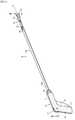
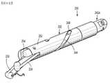
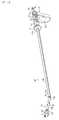
図1を参照すると、本開示の実施形態による外科用縫合器具は、概して100として識別される。外科用縫合器具100は、内視鏡または腹腔鏡の手技において特に有用となるように適合され、外科用縫合器具100のエンドエフェクタ130は、カニューレ組立体などを介して、手術部位の中に挿入可能である。外科用縫合器具100は、ハンドル組立体110と、ハンドル組立体110から遠位に延在するシャフト120と、シャフト120の遠位部分120bから延在するエンドエフェクタ130と、を含む。 With reference to FIG. 1, surgical suture instruments according to the embodiments of the present disclosure are generally identified as 100. The
図1~4を参照すると、外科用縫合器具100のハンドル組立体110は、作動組立体117及び関節運動組立体119の両方を支持する、ハンドルハウジング111を含む。ハンドルハウジング111は、固定ハンドル113及びハンドル113から実質的に垂直に延在する胴部分115を有する。ハンドル113は、その中またはその上に回転可能に支持された関節運動組立体119の関節運動ホイール121を有する。ハンドルハウジング111の胴部分115は、作動組立体117の摺動可能な受容のための空洞125を有する。 Referring to FIGS. 1-4, the
ハンドル組立体110の作動組立体117は、引き金127、作動シャフト129、及び作動シャフト129の近位部分129aに取り付けられたピン131を含む。ハンドルハウジング111に対する引き金127の動きが、胴部分115を通して、ピン131、次に作動シャフト129を動かすように、ピン131は引き金127に固定され、作動シャフト129の近位部分129aはピン131に固定される。作動組立体117の作動シャフト129は、胴部分115の空洞125を通して、ピン131から垂直に延在し、以下に詳細に説明されるように、引き金127の作動に応じて、エンドエフェクタ130の顎部材134、136を回転させる方法で、エンドエフェクタ130に動作可能に結合される遠位部分129bにおいて終端する。 The working
ハンドル組立体110の関節運動組立体119は、回転ホイール121、及び第1のロッド137の近位部分137aで回転ホイール121に動作可能に結合された第1のロッドまたはシャフト137を含む。第1のロッド137は、シャフト120を貫通する第2のロッド139の近位部分139aに取り付けられた遠位部分137bを有する。関節運動組立体119の第2のロッド139は、関節運動接合部、例えば関節運動ピン138に隣接する位置で、エンドエフェクタ130にピンで留められた遠位部分139b(図5)を有する。特に、関節運動組立体119の第2のロッド139は、第1及び第2のロッド137、139の長手方向運動が、回転ホイール121の回転を介して、2つの対向する方向のうちの1つに、関節運動ピン138を中心としてシャフト120に対してエンドエフェクタ130の関節運動をもたらすように、関節運動ピン138の半径方向外側に離間される(すなわち、シャフト120の中央長手方向軸からずれる)。 The articulated
外科用縫合器具100は、回転ツマミまたは回転ハウジング147をさらに含む。回転ツマミ147は、回転ツマミ147の回転が、シャフト120の長手方向軸「X」を中心としてシャフト120の回転をもたらすように、シャフト120の近位部分120aを中心として、回転して固定的に配置される。 The
図1及び4~7Bを参照すると、外科用縫合器具100のシャフト120は、ハンドルハウジング111の空洞125内に配置された近位部分120a、及び遠位部分120bを有する。外科用縫合器具100のエンドエフェクタ100は、シャフト120の遠位部分120bに枢動可能に結合される。エンドエフェクタ130は、細長本体部分132、及び本体部分132の遠位部分にそれぞれが枢動不可能に結合された第1及び第2の語部材134、136を概して含む。いくつかの実施形態において、顎部材134、136は、本体部分132の遠位部分に枢動可能に結合され得る。本体部分132は、上述の関節運動ピン138を介して、外科用縫合器具100のシャフト120の遠位部分120bに枢動可能に結合された近位部分を有する。かくして、エンドエフェクタ130は、上に説明された関節運動組立体119(図1)を介して、関節運動ピン138を中心としてシャフト120に対して関節運動可能である。 Referring to FIGS. 1 and 4-7B, the
いくつかの実施形態において、エンドエフェクタ130を関節運動させる原因となる関節運動組立体119の代わりに、本体部分132は、ハンドル組立体110から延在し、エンドエフェクタ130の本体部分132の反対側に接続された、一対のケーブル(図示せず)を使用して、シャフト120に対して枢動または関節運動され得る。手術中、1つのケーブルが近位に引かれるにつれて、他のケーブルは、シャフト120に対してエンドエフェクタ130を関節運動させるように遠位に押される(または外に出す)。本体部分132は、その全体の内容が参照により本明細書に組み込まれた、米国特許第8,292,905号に開示されている、1つ以上の同様の機構を使用して、関節運動し得ることが考えられる。 In some embodiments, instead of the articulating
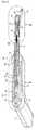
図1及び4~7Bを継続して参照すると、エンドエフェクタ130の本体部分132は、回転可能な外部シャフト140、及び外部シャフト140内に配置された回転可能な内部シャフト142を含む。第1及び第2の顎部材134、136が、以下に説明されるように、本体部分132によって画定された長手方向軸を中心として、内部シャフト142及び外部シャフト140の回転と共に回転するように、外部シャフト140は、その遠位部分に結合された第1の顎部材134を有し、内部シャフト142は、その遠位部分に結合された第2の顎部材136を有する。内部シャフト142の遠位部分142bは、外部シャフト140の遠位部分140bを越えて遠位に延在する。第1の顎部材134は、内部シャフト142の遠位部分142bが外部シャフト140の遠位部分140bを越えて遠位に延在する長さに実質的に等しい長さによって、第2の顎部材136よりも長い。かくして、第1及び第2の顎部材134、136の遠位端は、それらの間で縫合針10の交換を容易にするために、互いに整列される。 With reference to FIGS. 1 and 4-7B, the
本体部分132の外部シャフト140は、その中に形成された螺旋状カムスロット144を画定する。いくつかの実施形態において、カムスロット144は、例えば、ジグザグ状、波状などの様々なパターンを呈し得る。エンドエフェクタ130は、ハンドル組立体110の引き金127の作動に応じて、本体部分132の長手方向軸に沿って並進するように構成されている、作動バー146を含む。特に、作動バー146は、ハンドル組立体110の作動シャフト129の遠位部分129b(図5)に動作可能に結合された、近位部分146aを有する。いくつかの実施形態において、ハンドル組立体110の作動シャフト129及びエンドエフェクタ130の作動バー146は、互いに一体形成される。エンドエフェクタ130がシャフト120に対して関節運動するにつれて、作動バー146が可撓性細長部材149を中心として作動シャフト129に対して曲がるように、ハンドル組立体110の作動シャフト129は、シャフト120の関節運動ピン138に隣接する位置において配置された、可撓性細長部材149を介して作動バー146に結合される。いくつかの実施形態において、作動シャフト129及び作動バー146は、作動バー146が、エンドエフェクタ130の関節運動中に、作動シャフト129に対して曲がることを可能にする、可撓性材料からそれぞれが形成される。 The
エンドエフェクタ130の作動バー146は、外部シャフト140のカムスロット144内に摺動可能に受容される、第1の突起151aを有するT字形カム146bの形状の遠位部分を有する。エンドエフェクタ130の本体部分132に対して作動バー146が軸方向に並進すると、作動バー146のカム146bの第1の突起151aは、本体部分132の長手方向軸を中心として外部シャフト140を回転させ、次に、第1の顎部材134を回転させるために、外部シャフト140のカムスロット144を通って移動する。 The
本体部分132の内部シャフト142も、その中に形成された螺旋状カムスロット150を画定する。内部シャフト142のカムスロット150は、外部シャフト140のカムスロット144に対して角度が付けられる(例えば、カムスロット144、150は、互いに対して対向する螺旋状方向に走る)。作動バー146のカム146bの突起151aも、内部シャフト142のカムスロット150を通って延在する。外部シャフト140及び内部シャフト142のカムスロット144、150が、対向する方向に走っているので、作動バー146がエンドエフェクタ130の本体部分132内に並進されるにつれて、外部シャフト140及び内部シャフト142は反対方向に回転され、次に、第1の顎部材134及び第2の顎部材136は反対方向に回転される。 The
内部シャフト142は、カムスロット150から内部シャフト142の反対側に配置された、別のカムスロット153を画定し得る。カム148の第2の突起151bは、内部シャフト142の回転を容易にし、作動バー146の回転に抵抗するために、内部シャフト142の第2のカムスロット153を通って延在し得る。 The
いくつかの実施形態において、外科用縫合器具100は、ハンドル組立体110の別の引き金(図示せず)に動作可能に結合される、第2の作動バー(図示せず)を含み得る。内部シャフト142のカムスロット150を通って延在している、作動バー146のカム146bの代わりに、第2の作動バーは、内部シャフト142のカムスロット150を通って延在するその遠位端において、突起またはカムを有し得る。かくして、内部及び外部シャフト140、142は、それらのそれぞれの作動バーを使用して、互いに対して独立に回転され得る。 In some embodiments, the
図7A及び7Bを参照すると、第1及び第2の顎部材134、136は各々、近位部分及び遠位部分を有する。第1及び第2の顎部材134、136の各々の近位部分は、それぞれ外部シャフト140及び内部シャフト142に結合される。いくつかの実施形態において、第1及び第2の顎部材134、136は、例えばヒンジまたはナックル/クレビスといった結合部を介して、本体部分132に枢動可能に結合され得る。第1及び第2の顎部材134、136の各々の遠位部分は、湾曲縫合針10の端の着脱可能及び/または選択的な受容のために、サイズ決めかつ寸法決めされた穴または開口156、158をそれに画定する。穴156、158は、それぞれ第1及び第2の顎部材134、136の厚みを完全に貫通する。いくつかの実施形態において、穴156、158は、第1及び第2の顎部材134、136の厚みを部分的にのみ貫通し得る。 Referring to FIGS. 7A and 7B, the first and
針10が、外科手技中、第1及び第2の顎部材134、136に受け渡しされ得るように、穴156、158は、湾曲針10の端をそれに選択的に保つように構成される。特に、穴156、158の各々は、湾曲針10の対向する端を選択的に係合かつ解除するために、枢動可能な係合部分またはフックを有する、それに配置されたタッチラッチまたはプッシュラッチ(明示せず)を有し得る。加えて、湾曲針10の各対向する端は、顎部材134、136の穴156、158の各々に配置された、プッシュラッチを選択的に係合するように構成され、それに画定された穴または凹部を有し得る。
例えば、湾曲針10は第1の顎部材134に仮固定されるが、第2の顎部材136は第1の顎部材134から離間され、湾曲針10の第2の端から係脱されるように、開始状態における顎部材134、136で、湾曲針10の第1の端は第1の顎部材134のプッシュラッチに係合される。顎部材134、136が接近すると、湾曲針10の第2の端は、第1及び第2の顎部材134、136の両方のプッシュラッチに圧力を印加するため、第2の顎部材136の穴158を画定する内壁に係合する。湾曲針10の対向する第1及び第2の端によってプッシュラッチに印加されたこの圧力は、同時に、第1の顎部材134のプッシュラッチに湾曲針10の第1の端を係脱させ、第2の顎部材136のプッシュラッチに湾曲針10の第2の端を係合させるように、プッシュラッチを作動させる。第1及び第2の顎部材134、136を離間または分離させる際に、湾曲針10は、第2の顎部材136に取り付けられた状態を保ち、第1の顎部材134から解除される。 For example, the
いくつかの実施形態において、湾曲針10を顎部材134、136に選択的に取り付けかつ取り外すためのプッシュラッチを有する穴156、158よりもむしろ、穴156、158は、そこに配置された磁性半導体(図示せず)を有し得る。半導体は、電気的に誘起された強磁性として知られる現象を使用して、それに選択的に電圧を印加することによって、選択的にオン及びオフにされたそれらの磁気を有することができる種類の半導体である。特に、外科用縫合器具100は、ハンドル組立体110に配置された(または、ハンドル組立体110に結合された)発電機から延在し、顎部材134、136のそれぞれの半導体で終端する、2つのワイヤ(図示せず)を含み得る。ハンドル組立体110の発電機は、第1の顎部材134に保持された湾曲針10を有することが望ましいとき、第1の顎部材134の半導体の磁性をオンにするように、ワイヤを介して第1の顎部材134の半導体に電圧を印加し得る。第1の顎部材134から第2の顎部材136に湾曲針10を通すために、第1の顎部材134の半導体の磁性は、第1の顎部材134から湾曲針10の金属の第1の端を解除するようにオフにされる。第1の顎部材134の半導体の磁性をオフにすると同時に、第2の顎部材136の半導体の磁性は、第2の顎部材136の穴158に湾曲針10の金属の第2の端を保持するようにオンにされる。 In some embodiments, the
いくつかの実施形態において、顎部材134、136において湾曲針10を選択的に保持するために磁性半導体を使用する代わりに、外科用縫合器具100は、第1及び第2の顎部材134、136を通って画定されたチャネルを通って延在する、ワイヤまたは細径ケーブル(図示せず)を含み得る。ワイヤは、例えば、高分子弾性体、形状記憶合金、または形状記憶プラスチックといった弾性で展性のある材料から製造される。ワイヤは、第1及び第2の顎部材134、136の穴156、158に選択的に出入りするように、顎部材134、136を通って画定されたチャネルを通って反対長手方向に動くように構成される。ワイヤの遠位端は、湾曲針10が選択された顎部材134または136から外れることを防止するために、湾曲針10の反対端において画定された開口または窪み(図示せず)と相互係止するように構成される。特に、1つのワイヤが、そのそれぞれの顎部材134または136の穴156または158に入るにつれて、他のワイヤは、そのそれぞれの顎部材134または136の穴156または158から出ていく。このようにして、湾曲針10は、湾曲針10の端とワイヤのうちの1つの遠位端の係合が原因で、第1及び第2の顎部材134、136のいずれかの内に着脱可能に保持され得る。 In some embodiments, instead of using a magnetic semiconductor to selectively hold the
ブレードを使用して(ワイヤの代わりに)、縫合針を顎部材に選択的に係止するため、構造及び動作のより詳細な説明について、既に参照により本明細書に組み込まれた、米国特許第8,292,905号、及び米国特許第5,674,229号に対して、参照がなされ得る。 U.S. Pat. References may be made to 8,292,905 and US Pat. No. 5,674,229.
手術中、組織の縫合、例えば、ヘルニア修復を伴う低侵襲の手技を実行する際、患者の身体内の手術部位に接近するために、アクセス管またはカニューレが患者の表面組織を通して位置付けられる。顎部材134、136を、対象とする組織に隣接して、湾曲針10で位置付けるために、外科用縫合器具100がカニューレに通される。組織を縫合するように湾曲針10(それに取り付けられた縫合糸を有する)を組織に通すために、顎部材134、136は、離間位置から近接位置に回転される。 During surgery, when performing tissue sutures, eg, minimally invasive procedures involving hernia repair, an access tube or cannula is positioned through the patient's surface tissue to access the surgical site within the patient's body. A
エンドエフェクタ130の本体部分132の長手方向軸を中心として顎部材134、136を回転させるために、ハンドル組立体110の引き金127は、ハンドル組立体110の作動シャフト129を近位方向に移動させるように作動される。ハンドル組立体110の作動シャフト129に結合されているエンドエフェクタ130の作動バー146が原因で、作動シャフトの近位移動は、本体部分132を通る作動バー146の近位移動をもたらす。作動バー146のカム146bは、外部シャフト140及び内部シャフト142の、それぞれのカムスロット144、150を通って移動し、図7Aの矢印「A」及び「B」によって示された、外部及び内部シャフト140、142の回転を対向する方向に駆動させる。顎部材134、136は、それぞれ外部シャフト140、内部シャフト142に結合されているので、顎部材134、136は、組織を通る本体部分132の長手方向軸「X」を中心として円形経路に沿って針10を駆動するために、外部及び内部シャフト140、142と共に互いに向かって回転される。 In order to rotate the
顎部材134、136の回転は、第2の顎部材136の穴158が湾曲針10の端を受容するまで、継続される。湾曲針10は、上に説明されたタッチラッチまたは他の適切な機構を使用して、第1の顎部材134から第2の顎部材136まで移動される。湾曲針10が第2の顎部材136に接続されている場合、引き金127が解除され、ばね(図示せず)が引き金127を非作動位置に移動させることを可能にし、それによって、ハンドル組立体の作動シャフト129を遠位方向に開始位置まで後退させる。作動シャフト129の遠位移動は、エンドエフェクタ130の作動バー146を、エンドエフェクタ130の本体部分132を通して遠位方向に押すまたは駆動させる。作動バー146の遠位方向への移動は、外部及び内部シャフト140、142のカムスロット144、150を通って、作動バー146のカム146bを移動させ、その結果、外部及び内部差シャフト140、142の回転を駆動させ、次に、図7Bの矢印「C」及び「D」によって示された方向に、互いから離れて、第1及び第2の顎部材134、136の回転を駆動させる。この過程は、対象となる組織が縫合されるまで継続され得る。 The rotation of the
図8A~9Eを参照すると、外科用縫合器具のエンドエフェクタ230の別の実施形態が提供される。エンドエフェクタ230は、エンドエフェクタ230によって画定された長手方向軸を中心としてその顎部材のただ1つを回転させるように構成されているという相違があるが、エンドエフェクタ230は、図1~7Bを参照して上に説明されたエンドエフェクタ130と類似している。したがって、エンドエフェクタ230は、実施形態間の特定の相違を明瞭にする必要のある詳細において、説明されるのみであろう。 Referring to FIGS. 8A-9E, another embodiment of the
エンドエフェクタ230は、例えば、図1のハンドル組立体110、または他の適切な作動機構といったハンドル組立体によって遠隔操作可能であり得る。エンドエフェクタ230は、細長本体部分232、及び各々が本体部分232の遠位部分に枢動可能に結合された第1及び第2の顎部材234、236を概して含む。上に説明されたエンドエフェクタ130とは異なり、エンドエフェクタ230は、第1及び第2の顎部材234、236の両方ではなく、本体部分232によって画定された長手方向軸「X」を中心として第1の顎部材234のみを回転させるように構成されている。 The
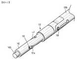
エンドエフェクタ230の本体部分232は、例えば図1のシャフト120といったシャフトの遠位部分に枢動可能に結合されるように構成された近位部分を有する。かくして、エンドエフェクタ230は、シャフト120に対して関節運動可能である。エンドエフェクタ230の本体部分232は、回転可能な外部シャフト240、及び外部シャフト240内に配置された内部シャフト242を含む。外部シャフト240は、枢軸ピン241を介してそれの遠位部分240bに枢動可能に結合された第1の顎部材234を有し、内部シャフト242は、枢軸ピン243を介してそれの遠位部分242bに枢動可能に結合された第2の顎部材236を有する。内部シャフト242の遠位部分242bは、外部シャフト240の遠位部分240bを越えて遠位に延在し、その結果、第2の顎部材236が、外部シャフト240の遠位部分240bからの干渉なしで、本体部分232から外側に枢動することを可能にする。 The
外部シャフト240は、その中に形成された螺旋状カムスロット244を画定する。いくつかの実施形態において、カムスロット244は、例えば、ジグザグ状、波状などの様々なパターンを呈し得る。エンドエフェクタ230は、ハンドル組立体110の引き金127の作動に応じて、本体部分232の長手方向軸「X」に沿って並進するように構成されている、作動バー246を含む(図1)。作動バー246は、外部シャフト240のカムスロット244内に摺動可能に受容されている、ピンまたはカム248を通って延在する。エンドエフェクタ230の本体部分232に対する作動バー246の軸方向並進の際に、カム248は、外部シャフト240に、本体部分232の長手方向軸「X」を中心として回転させ、次に、第2の顎部材236に対して接近または離間して第1の顎部材234を回転させるように、外部シャフト240のカムスロット244を通して移動される。 The
外部シャフト240の遠位部分240bは、長手方向に延在しているスロット252を画定する。第1の顎部材234が図9Aに示されるような閉構成にあるとき、第1の顎部材234は、外部シャフト240のスロット252を通って延在する。内部シャフト242は、それの中間部分において長手方向に延在しているスロット253を画定する。カム248は、内部シャフト242のスロット253を通って延在し、作動バー246によるカム248の動作中、スロット253によって長手方向軸「X」に沿って誘導される。内部シャフト242は、内部シャフト242の遠位部分242bに位置する、横方向に延在しているスロット254も画定する。外部及び内部シャフト240、242が、図9Aに示されるような第1の位置にあるとき、内部シャフト242のスロット254は、第1の顎部材234の受容のための1つの連続した細長スロットを形成するために、外部シャフト240のスロット252と整列される。いくつかの実施形態において、外部シャフト240の遠位部分240b及び/または内部シャフト242の遠位部分242bは、それに形成された追加のスロットを有し得る。 The
内部シャフト242は、ハンドル組立体110の作動機構(図示せず)に動作可能に結合されている、近位部分242aを有する。このようにして、エンドエフェクタ230の内部シャフト242は、近位方向または遠位方向のいずれかに外部シャフト240に対して長手方向に可動され得る。図9Bに示されるように、内部シャフト242の遠位部分242bは、第1及び第2の顎部材234、236に対する内部シャフト242の近位移動が、第1の顎部材234がスロット252、254を通って延在する第1の位置から、第1及び第2の顎部材234、236が本体部分232に対して外側へ広げられる第2の位置まで、第1及び第2の顎部材234、236を持ち上げるような傾斜面を有することが考えられる。いくつかの実施形態において、エンドエフェクタ230は、互いに対して顎部材234、236を枢動させることができる任意の適切な機構を含み得る。エンドエフェクタ230は、第1の閉位置に向けて顎部材234、236を弾性的に付勢する付勢要素、例えば、ばねを含むことが考えられる。 The
第1及び第2の顎部材234、236の各々の遠位部分は、上に説明された顎部材134、136の穴156、158と類似した、穴または開口256、258をその中に画定する。穴256、248は、それぞれ第1及び第2の顎部材234、236の厚みを完全に貫通する。いくつかの実施形態において、穴256、258は、第1及び第2の顎部材234、236の厚みを部分的にのみ貫通し得る。針10が、外科手技中に第1及び第2の顎部材234、236と受け渡しされ得るように、穴256、258は、そこに湾曲針10の端を選択的に保持するように構成される。これは、上に説明された任意の機構、例えばプッシュラッチを使用して達成され得る。 Each distal portion of the first and
手術中、組織を縫合すること、例えば、ヘルニア修復を伴う低侵襲の手技を実行するため、アクセス管またはカニューレが、患者の身体内の手術部位に接近するように、患者の表面組織を通して位置付けられる。エンドエフェクタ230の第1及び第2の顎部材234、236は、第1及び第2の顎部材234、236が本体部分232の長手方向軸「X」と平行であり、本体部分232の外部及び内部シャフト240、242のスロット252、254内に入れ子にされている、閉構成に移動される。第1及び第2の顎部材234、236が閉構成にある場合、エンドエフェクタ230は、顎部材234、236を、湾曲針10で、対象となる組織に隣接して位置付けるように、カニューレに通される。本体部分232の内部シャフト242は、外部シャフト240に対して近位に移動され、それによって、互いから離れた顎部材234、236を開構成に枢動させるように、内部シャフト242の傾斜面(図示せず)を第1及び第2の顎部材234、236に沿って近位に移動させる。 During surgery, the access tube or cannula is positioned through the patient's surface tissue to approach the surgical site within the patient's body in order to perform a minimally invasive procedure involving suturing tissue, eg, hernia repair. .. In the first and
顎部材234、236が開構成にあり、第1の顎部材234の遠位部分が本体部分232の外部及び内部シャフト240、242の各々のスロット252及び254の外側にある場合、作動バー246は、本体部分232を通って遠位方向に移動される。作動バー246が遠位に移動されるにつれて、カム248は、図9Cの矢印「E」によって示される方向に内部シャフト242に対して外部シャフト240の回転を駆動するように、外部シャフト240のカムスロット244を通って遠位に移動する。第1の顎部材234が外部シャフト240に結合されるので、第1の顎部材234は、本体部分232の長手方向軸「X」を中心として円形経路に沿った組織を通って針10を駆動するように、第2の顎部材236に向かって外部シャフト240と共に回転される。第1の顎部材234の回転は、第2の顎部材236の穴258が湾曲針10の反対または第2の端を受容するまで継続される。湾曲針10は、第1の顎部材234から第2の顎部材236まで移される。 When the
湾曲針10が第2の顎部材236に接続される場合、作動バー246は、エンドエフェクタ230の本体部分232を通って近位方向に作動バー246を移動するように、作動させられ得る。近位方向への作動バー246の移動は、外部シャフト240の回転、次に、第2の顎部材236から離れて、第1の顎部材236の回転を駆動するように、外部シャフト240のカムスロット244を通ってカム248を近位に移動させる。この過程は、対象となる組織が縫合されるまで継続され得る。 When the
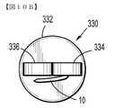
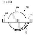
図10A~12Cを参照すると、図1~9Eに関連して上に説明された外科用縫合器具100と同様に、外科用縫合器具のエンドエフェクタ330が提供される。エンドエフェクタ330は、図1~9Eに関連して上に説明されたエンドエフェクタ130、230のいずれかと類似している。したがって、エンドエフェクタ330は、実施形態間の特定の相違を明瞭にする必要のある詳細において説明されるのみであろう。エンドエフェクタ330は、例えば、図1のハンドル組立体110または任意の他の適切な作動機構といったハンドル組立体によって、遠隔で動作可能であり得る。 With reference to FIGS. 10A-12C, the
エンドエフェクタ330は、本体部分332と、本体部分332に枢動可能に結合された第1及び第2の顎部材334、336と、を含む。第1及び第2の顎部材334、336のそれぞれの遠位部分は、上に説明されている穴156、148と同様の穴または開口356、358をそこに画定する。穴356、358は、第1の額部材334、第2の額部材336の厚みを完全に貫通する。いくつかの実施形態において、穴356、358は、第1の額部材334、第2の額部材336の厚みを部分的にのみ貫通し得る。穴356、358は、針10が、外科手技中、第1及び第2の額部材334、336と受け渡しされ得るような、湾曲針10の端をそこに選択的に保持するように構成されている。 The
エンドエフェクタ330は、第1の顎部材334の穴356内に枢動可能に配置された、例えば、ボール形状の要素の形態における入れ子などのカップ部材を含む。エンドエフェクタ330が、第2の顎部材336の穴358内に枢動可能に配置された第2の入れ子を含み得ることが考えられる。入れ子は、そこに湾曲針10の端を保持し、かつ第1の顎部材334に対して枢動し、それにより、第1の顎部材334に対して湾曲針10を枢動させるように、構成されている。エンドエフェクタ330が、ハンドル組立体110(図1)に動作可能に結合され、また、作動器ロッドの作動が、穴356内で、また第1の顎部材334に対して、入れ子を回転させるような、入れ子に動作可能に結合された、作動器ロッド(図示せず)を含み得ることが考えられる。 The
手術中、組織を縫合すること、例えばヘルニア修復を伴う低侵襲の手技を実行するために、アクセス管またはカニューレは、患者の身体内の手術部位に接近するように、患者の表面組織を通して位置付けられる。エンドエフェクタ330の第1及び第2の顎部材334、336は、第1及び第2の顎部材334、336が本体部分332と平行である、閉構成に移動させられる。湾曲針10が、図10A及び10Bに示されているように、顎部材334、336に隣接して配置されるか、またはそれらと当接係合するように、第1の顎部材334の入れ子が操作される。湾曲針10が第1の顎部材334に隣接する場合、エンドエフェクタ330の側面全体が、縮小され、エンドエフェクタ330が、より小さな寸法のカニューレまたはアクセス管に通されることを可能にする。 During surgery, to suture tissue, eg, to perform minimally invasive procedures involving hernia repair, the access tube or cannula is positioned through the patient's surface tissue to approach the surgical site within the patient's body. .. The first and
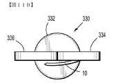
第1及び第2の顎部材334、336が閉構成にあり、湾曲針10が第1の顎部材334と隣り合わせである場合、顎部材334、336を、湾曲針10で、対象となる組織に隣接して位置付けるために、エンドエフェクタ330がカニューレに通される。図11A及び11Bに示されているように、組織を縫合する準備の際、顎部材334、336が互いに離れて開構成に枢動される。 When the first and
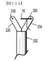
図12A~12Cを参照すると、顎部材334、336が開構成にある場合、図12Bの矢印「F」によって示された方向に、入れ子を回転させ、それにより、湾曲針10を第1の顎部材334から離れて外向きに回転させるように、エンドエフェクタ330の作動器ロッドが作動される。湾曲針10によって画定された軸が、第1及び第2の顎部材334、336のそれぞれの穴356、358と整列されるまで、湾曲針10は入れ子を介して回転される。いくつかの実施形態において、補助的な外科用器具、例えば把持具が、第1の顎部材334に対して外向きに湾曲針10を手動で回転させるのに提供され得る。第1の顎部材334及び/または第2の顎部材336は、上に説明されたものと同様に、針10を組織に通すように、回転され得る。 Referring to FIGS. 12A-12C, when the
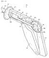
図13~18Cを参照すると、外科用縫合器具の別の実施形態が、全体的に400として、示され、識別されている。外科用縫合器具400は、上に説明された外科用縫合器具100と同様であり、したがって、それら間の特定の相違を明瞭にするために必要である場合のみ、詳細に説明される。外科用縫合器具400は、ハンドル組立体410、ハンドル組立体410から遠位に延在するシャフト420、及びシャフト420の遠位部分420bから延在するエンドエフェクタ430を含む。 With reference to FIGS. 13-18C, another embodiment of the surgical suture instrument is shown and identified as 400 overall. The
外科用縫合器具400のハンドル組立体410は、作動組立体417及び関節運動組立体419を支持するハンドルハウジング411を含む。ハンドルハウジング411は、ハンドル413、及びハンドル413からほぼ垂直に延在する胴部分415を有する。ハンドル413は、それに回転可能に支持された関節運動組立体419の関節運動ホイール421を有する。ハンドルハウジング411の胴部分414は、そこに画定された長手方向に延在するスロット423、及びそこに画定された空洞425を有する。 The
ハンドル組立体410の作動組立体417は、引き金427、作動シャフト429、及び作動シャフト429の近位部分に取り付けられたピン429aを含む。胴部分415のスロット423は、その中を横方向に貫通する、作動組立体417のピン429aを有する。ピン429は、ハンドルハウジング411に対する引き金427の移動がピン429aを胴部分415のスロット423に入れるような、引き金427に画定された垂直配向のスロット433内にも貫通する。作動組立体417の作動シャフト429は、ピン429aから胴部分415の空洞425を通り、垂直に延在し、また、以下により詳細に説明されるように、引き金427の作動の際に、エンドエフェクタ430の顎部材434、436を回転させるように、エンドエフェク430に動作可能に結合されている遠位部分429bにおいて終端する。 The working
ハンドル組立体410の関節運動組立体419は、細長部材437と、細長部材437から遠位に延在する関節運動バー439と、ハンドルハウジング411のハンドル413において回転可能に支持されている関節運動ホイール421と、を含む。関節運動組立体419の細長部材437は、近位部分437a及び管状遠位部分437bを含む。細長部材437の近位部分437aは、関節運動ホイール421において画定されたチャネル443に受容されている、それから延在するピン441を有する。関節運動ホイール421のチャネル443は、関節運動ホイール421の回転軸を中心に、半径方向に内向き/外向きに螺旋状になり、2つの両端壁445a、445bによって画定された2つの両端を有する。細長部材437のピン441が、関節運動ホイール421が回転する軸から半径方向距離離れて配置されている。いくつかの実施形態において、細長部材437のピン441は、関節運動ホイール421が回転する軸の上方/下方に配置され得る。手術中、関節運動ホイール421の回転は、関節運動ホイール421のチャネル443の端壁445a、445bを、細長部材437のピン441と係合させ、ハンドルハウジング111の胴部分415を通る細長部材437の近位または遠位移動のうちの1つを駆動する。 The
図15~17を参照すると、関節運動シャフト439が長細部材437と共に移動するように、関節運動組立体419の関節運動シャフト439は、細長部材437の管状遠位部分437b内に配置された近位部分439aを有し、それの内面に固定される。関節運動組立体419の関節運動シャフト439は、関節運動接合部、例えば関節運動ピン438に隣接する位置にあるエンドエフェクタ430に動作可能に結合された遠位部分439bを有する。具体的には、関節運動組立体419の関節運動シャフト439は、回転ホイール421の回転を介した、関節運動シャフト439の長手方向移動が、2つの対向する方向のうちの1つの方向における、関節運動ピン438を中心とした、シャフト420に対するエンドエフェクタ430の関節運動をもたらすように、関節運動ピン438の半径方向外向きに離間されている(すなわち、シャフト420の中央長手方向軸からずれている)。 Referring to FIGS. 15-17, the
ハンドル組立体410は、外科用縫合器具400のシャフト420の周りに配置され、それに回転可能に固定された回転ホイール447をさらに含む。このように、外科用縫合器具400のシャフト420は、回転ホイール447の回転に応じて、その長手方向軸を中心に回転する。外科用縫合器具400のシャフト420は、ハンドルハウジング411の空洞425内に配置された近位部分420a、及び遠位部分420bを有する。外科用縫合器具400のエンドエフェクタ400は、シャフト420の遠位部分420bに枢動可能に結合されている。 The
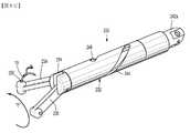
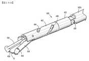
図17及び18A~18Cを参照すると、エンドエフェクタ430は、通常、長細本体部分432と、それぞれがエンドエフェクタ430の本体部分432に枢動可能に結合されている、第1及び第2の顎部材434、436と、を含む。いくつかの実施形態において、顎部材434、436は、本体部分432に対して枢動不能であり得、または、他の実施形態において、額部材434、436のうちの1つのみが、本体部432に対して枢動可能であり得る。本体部分432は、上述の関節運動ピン438を介して外科用縫合器具400のシャフト420の遠位部分420bに枢動可能に結合された近位部分有する。したがって、エンドエフェクタ430は、上に説明された関節運動組立体419(図13)を介して、関節運動ピン438を中心に、シャフト420に対して間接運動可能である。 With reference to FIGS. 17 and 18A-18C, the
エンドエフェクタ420の本体部分432は、回転可能な外部シャフト440と、外部シャフト440内に回転不能に配置された内部シャフト442と、を含む。外部シャフト440は、それの遠位部分に結合された第1の額部材434を有し、内部シャフト442は、それの遠位部分に結合された第2の額部材436を有し、それによって、第1の額部材434が、外部シャフト440の回転と共に、第2の顎部材436に対して回転するようにする。本体部分432の外部シャフト440は、そこに形成された螺旋状カムスロット444を画定する。いくつかの実施形態において、カムスロット444は、様々なパターン、例えばジクザク状、波状などのパターンを呈し得る。エンドエフェクタ430は、ハンドル組立体410の引き金427の作動に応じて、本体部分432の長手方向軸に沿って並進するように構成されている、作動バー446を含む。 The
具体的には、作動バー446は、ハンドル組立体410の作動ロッド429の遠位部分429bに結合された近位部分446a(図17)を有する。いくつかの実施形態において、ハンドル組立体410の作動シャフト429及びエンドエフェクタ430の作動バー446は、互いに一体的に形成されている。エンドエフェクタ430がシャフト420に対して関節運動するのに従って、作動バー446が、可撓性細長部材449を中心に、作動シャフト429に対して曲がるように、ハンドル組立体410の作動シャフト429は、シャフト420の関節運動ピン438に隣接する位置に配置された可撓性細長部材449を介して、作動バー446に結合されている。いくつかの実施形態において、作動シャフト429及び作動バー446は、作動バー446が、エンドエフェクタ430の関節運動中、作動シャフト429に対して撓むことを可能にする可撓性材料からそれぞれ形成されている。 Specifically, the actuating bar 446 has a
作動バー446は、外部シャフト440のカムスロット444内に摺動可能に受容されている突起またはカム448を有する遠位部分446bを有する。本体部分432に対する作動機構446の軸方向並進を受けて、突起448は、外部シャフト440のカムスロット444を通って移動し、本体部分432の長手方向軸を中心に外部シャフト440を回転させ、次に、第1の額部材434を回転させる。 The actuating bar 446 has a
本体部分432の内部シャフト442は、接合部、例えば関節運動ピン438を介してシャフト420の遠位部分420bに枢動可能に結合されている一方、シャフト420の長手方向軸を中心としたシャフト420に対する回転が不能である。額部材436は、内部シャフト442の遠位部分に枢動可能に結合されている。このように、内部シャフト442は、額部材434が、本体部分432の長手方向軸を中心として内部シャフト442に対して回転するのを防止しながら、エンドエフェクタ430を、シャフト420に対して間接運動可能である状態にする。本体部分432の内部シャフト442は、中を貫通する作動バー446のカム448を有する長手方向に延在するスロット450を画定する。内部シャフト442のスロット450は、本体部分432を通る直線においてカム448を誘導するように機能する。 The
引き続き図18A~18Cを参照すると、第1及び第2の額部材434、436のそれぞれの遠位部分は、上に説明されている穴156、158と同様の穴または開口456、458をそこに画定する。穴456、448は、それぞれ、第1の顎部材434、第2の顎部材436の厚みを完全に貫通する。いくつかの実施形態において、穴456、458は、第1の顎部材434、第2の顎部材436の厚みを部分的にのみ貫通し得る。穴456、458は、針10が、外科手技中、第1及び第2の顎部材434、436と受け渡しされ得るような、湾曲針10の端をそこに選択的に保持するように構成されている。これは、上に説明されている機構、例えばプッシュラッチのうちのいずれかを使用して達成され得る。 Continuing with reference to FIGS. 18A-18C, the respective distal portions of the first and
手術中、組織を縫合すること、例えばヘルニア修復を伴う低侵襲の手技を実行する際、患者の身体内の手術部位に接近するために、アクセス管またはカニューレが患者の表面組織を通して位置付けられる。顎部材434、436を、対象となる組織に隣接して、湾曲針10で位置付けるように、エンドエフェクタ430がカニューレに通される。エンドエフェクタ430の作動バー446は、引き金427の作動に応じて、本体部分232を通って、遠位方向に移動させられる。作動バー446が、遠位に移動させられるにつれ、カム448は、外部シャフト440のカムスロット444を通って、遠位に移動し、内部シャフト442に対する外部シャフト440の回転を駆動する。第1の顎部材434が外部シャフト440に結合されていることから、本体部分432の長手方向軸を中心とした円形経路に沿って、組織に針10を通すために、第1の顎部材434が、第2の顎部材436に向かって外部シャフト440と一緒に回転される。第1の顎部材434の回転は、第2の顎部材436の穴458が、湾曲針10の端を受容し、第1の額部材434から2の顎部材436に湾曲針10を移動させるまで、継続される。 During surgery, when suturing tissue, eg, performing a minimally invasive procedure involving hernia repair, an access tube or cannula is positioned through the patient's surface tissue to access the surgical site within the patient's body. The
第2の額部材436に接続された湾曲針10で、作動バー446は、エンドエフェクタ430の本体部432を通って、近位方向に作動バー446を移動させるように作動させられ得る。近位方向の作動バー446の移動は、カム448を、外部シャフト440の回転を駆動するように、外部シャフト440のカムスロット444を通って近位方向に移動させ、次は、第1の顎部材436を、第2の顎部材436から離して移動させる。この過程は、対象となる組織が縫合されるまで継続され得る。 With the
本明細書に説明されている、外科用縫合器具、またはそれのエンドエフェクタはまた、ロボット外科用システムと共に働くように構成され得、それは、一般に「遠隔手術」と称される。このようなシステムは、様々なロボット要素を採用し、外科医を補助し、外科用器具類の遠隔操作(または、部分的遠隔操作)を可能にする。様々なロボットアーム、歯車、カム、滑車、電動及び機械式モータなどがこの目的で採用され得、手術または治療の進行中、外科医を補助するように、ロボット外科用システムと一緒に設計され得る。このようなロボットシステムは、遠隔操作可能なシステム、自動可撓性の外科用システム、遠隔可撓性の外科用システム、遠隔関節運動式外科用システム、無線外科用システム、モジュール式または選択的構成可能な遠隔操作式外科用システムなどを含み得る。 The surgical suture instrument, or end effector thereof, described herein can also be configured to work with a robotic surgical system, which is commonly referred to as "remote surgery". Such systems employ a variety of robotic elements to assist surgeons and enable remote (or partial remote control) of surgical instruments. Various robot arms, gears, cams, slides, electric and mechanical motors, etc. may be employed for this purpose and may be designed with a robotic surgical system to assist the surgeon during surgery or treatment. Such robotic systems can be remote controlled systems, automatic flexible surgical systems, remote flexible surgical systems, remote articulated motor surgical systems, wireless surgical systems, modular or selective configurations. It may include possible remote controlled surgical systems and the like.
ロボット外科用システムは、手術室の隣にある、または遠隔位置に位置する、1つまたは複数の制御盤と一緒に採用され得る。この場合、外科医または看護師のあるチームは、患者に手術の用意をさせ、ロボット外科用システムを、本明細書に開示されている外科用縫合器具、またはそれの構成要素のうちの1つまたは複数で構成し得る一方、別の外科医(または、外科医のグループ)は、ロボット外科用システムを介して、器具を遠隔で制御する。理解され得るように、高度熟練の外科医は、彼/彼女の遠隔制御盤を離れることなく、複数の位置で複数の手術を実行し得、これは、患者または一連の患者に対して、経済的に有利でもあり利益でもあり得る。 The robotic surgical system may be employed with one or more control panels located next to or remotely located in the operating room. In this case, a team of surgeons or nurses prepares the patient for surgery and the robotic surgical system is one of the surgical suture instruments disclosed herein, or one of its components. While it can consist of multiple surgeons, another surgeon (or group of surgeons) remotely controls the instrument via a robotic surgical system. As can be understood, a highly skilled surgeon can perform multiple surgeries in multiple locations without leaving his / her remote control panel, which is economical for a patient or a series of patients. It can be both advantageous and profitable.
外科用システムのロボットアームは、通常、コントローラによって主ハンドル対に結合される。本明細書に開示されている実施形態のうちの1つ以上の使用を補完し得る、任意のタイプの外科用器具(例えば、エンドエフェクタ、把持具、ナイフ、ハサミなど)の作業端の対応する移動をもたらすために、ハンドルが、外科医によって移動させられ得る。作業端が、外科医の操作手によって実行される移動と異なる、それよりも小さい、またはそれよりも大きい対応する移動を有するように、主ハンドルの移動が拡大縮小され得る。技師が、外科用器具の作業端の解像度を制御することができるように、倍率または歯車比が調整可能であり得る。 The robotic arm of a surgical system is typically coupled to a pair of main handles by a controller. Corresponding working ends of any type of surgical instrument (eg, end effector, gripper, knife, scissors, etc.) that may complement the use of one or more of the embodiments disclosed herein. The handle can be moved by the surgeon to result in movement. The movement of the main handle can be scaled so that the working edge has a corresponding movement that is different, smaller, or larger than the movement performed by the surgeon's operator. The magnification or gear ratio may be adjustable so that the technician can control the resolution of the working edge of the surgical instrument.
主ハンドルは、様々な組織パラメータまたは状態、例えば、触診、切除、そうでなければ処置による組織抵抗、組織への器具による圧力、組織温度、組織インピーダンスなどに関する、フィードバックを外科医に与えるための様々なセンサを含み得る。理解され得るように、このようなセンサは、実際の手術状態をシミュレートする向上した触覚フィードバックを外科医に与える。主ハンドルは、実際の手術状態を模倣するように、外科医の手腕をさらに高める、繊細な組織触診または処置用の様々な異なる作動器も含み得る。 The main handle provides the surgeon with various tissue parameters or conditions, such as tactile, excision, otherwise tissue resistance, instrumental pressure, tissue temperature, tissue impedance, etc. May include sensors. As can be understood, such sensors provide the surgeon with improved tactile feedback that simulates the actual surgical condition. The main handle may also include a variety of different actuators for delicate tissue palpation or procedure that further enhance the surgeon's abilities to mimic the actual surgical condition.
図19を参照すると、1つの例示的なロボット外科システムまたは医療ワークステーション1000は、一般に、複数のロボットアーム1002、1003、制御装置1004、及び制御装置1004と結合された操作卓1005を含み得る。操作卓1005は、特に3次元画像を表示するようにセットアップされ得る、表示装置1006を含み得、人(図示せず)、例えば外科医による手動入力装置1007、1008は、第1の動作モードにおいて、ロボットアーム1002、1003を遠隔操作することが可能であり得る。 Referring to FIG. 19, one exemplary robotic surgical system or
ロボットアーム1002、1003のそれぞれは、継手を通して接続されている複数の部材と、例えば、以下にさらに詳細に説明される、本明細書に開示されたエンドエフェクタ130、230、330、または430のいくつかの実施形態のうちのいずれか1つによる、エンドエフェクタ1100を支持する外科用具「ST:Surgical Tool」が取り付けられ得る、取り付け装置1009、1011と、を含み得る。 Each of the
ロボットアーム1002、1003は、制御装置1004に接続されている電気駆動部(図示せず)によって駆動され得る。制御装置1004(例えば、コンピュータ)は、ロボットアーム1002、1003、それらの取り付け装置1009、1011、またそれにより外科用具(エンドエフェクタ1100を含む)が、手動入力デバイス1007、1008によって規定される移動に従った、所望の移動を実行するように、特にコンピュータプログラムにより駆動部を作動させるようにセットアップされ得る。制御装置1004は、それが、ロボットアーム1002,1003の及び/または駆動部の移動を調整するようにも、セットアップされ得る。 The
医療ワークステーション1000は、エンドエフェクタ1100によって、低侵襲式に処置されるべき、患者テーブル1012に横たわる患者1013において使用するように構成される。医療ワークステーション1000は、2本のロボットアーム1002、1003より多くのロボットアームも含み得、追加のロボットアームは、同様に、制御装置1004に接続され、操作卓1005によって遠隔操作可能である。医療器具または外科用具(エンドエフェクタ1100を含む)は、追加のロボットアームにも取り付けられ得る。医療ワークステーション1000は、例えば、患者/生体1013からの術前データ及び/または解剖学アトラスが保存されている、特に制御装置1004に結合されたデータベース1014を含み得る。 The
例示的なロボット外科システムの構成及び動作のより詳細な考察のために、全体の内容が参照により本明細書に組み込まれている、「Medical Workstation」と題された、米国特許出願公開第2012/0116416号が、本明細書において参照されている。 For a more detailed discussion of the configuration and operation of an exemplary robotic surgical system, US Patent Application Publication No. 2012 / entitled "Medical Workstation", the entire contents of which are incorporated herein by reference. 0116416 is referred to herein.
本明細書に開示された実施形態に、様々な修正がなされ得ることが理解されるであろう。したがって、上の「発明を実施するための形態」は、制限的と解釈されるべきではなく、単に実施形態の例示と解釈されるべきである。当業者は、添付の請求項の範囲及び趣旨内で、他の修正を想到するであろう。 It will be appreciated that various modifications can be made to the embodiments disclosed herein. Therefore, the above "mode for carrying out the invention" should not be construed as restrictive, but merely as an example of the embodiment. Those skilled in the art will conceive other amendments within the scope and intent of the accompanying claims.
Claims (7)
Translated fromJapaneseハンドル組立体と、
前記ハンドル組立体から遠位に延在するシャフトと、
エンドエフェクタであって、
前記シャフトに結合され、長手方向軸を画定する、本体部分であって、前記本体部分は、
回転可能な外部シャフトと、
前記外部シャフト内に配置された内部シャフトと
を含む、本体部分、
前記外部シャフトの遠位部分に枢動可能に結合され、前記本体部分の前記長手方向軸を中心として回転可能な第1の顎部材であって、湾曲針の着脱可能な受容のために構成された穴を画定する、第1の顎部材、及び、
前記第1及び第2の顎部材が、前記第2の顎部材に向けた前記本体部分の前記長手方向軸を中心とした前記第1の顎部材の回転の際に、それらの間に湾曲針を移すように、前記内部シャフトの遠位部分に枢動可能に結合され、湾曲針の着脱可能な受容のために構成された穴を画定する、第2の顎部材
を含む、エンドエフェクタと
を備える、外科用縫合器具。Surgical suture device
With the handle assembly,
A shaft extending distally from the handle assembly,
It ’s an end effector,
A body portion that is coupled to the shaft and defines a longitudinal axis, said body portion.
With a rotatable external shaft,
With the internal shaft arranged in the external shaft
Including, body part ,
A first jaw member pivotally coupled tothe distal portion of the external shaft and rotatable about the longitudinal axis of the body portion, configured for removable reception of the curved needle. The first jaw member, which defines the hole, and
When the first and second jaw members rotate the first jaw member about the longitudinal axis of the main body portion toward the second jaw member, a curved needle is inserted between them. A second jaw member that is pivotally coupled tothe distal portion of the internal shaft and defines a hole configured for removable reception of the curved needle so as to transfer.
With end effectors, including
A surgical sutureinstrument .
Applications Claiming Priority (4)
| Application Number | Priority Date | Filing Date | Title |
|---|---|---|---|
| US201762462512P | 2017-02-23 | 2017-02-23 | |
| US62/462,512 | 2017-02-23 | ||
| US15/863,806US10595855B2 (en) | 2017-02-23 | 2018-01-05 | Surgical suturing instruments |
| US15/863,806 | 2018-01-05 |
Publications (2)
| Publication Number | Publication Date |
|---|---|
| JP2018134396A JP2018134396A (en) | 2018-08-30 |
| JP7083653B2true JP7083653B2 (en) | 2022-06-13 |
Family
ID=61256768
Family Applications (1)
| Application Number | Title | Priority Date | Filing Date |
|---|---|---|---|
| JP2018016954AActiveJP7083653B2 (en) | 2017-02-23 | 2018-02-02 | Surgical suture device |
Country Status (4)
| Country | Link |
|---|---|
| US (1) | US10595855B2 (en) |
| EP (1) | EP3366227A1 (en) |
| JP (1) | JP7083653B2 (en) |
| CN (1) | CN108498126B (en) |
Cited By (1)
| Publication number | Priority date | Publication date | Assignee | Title |
|---|---|---|---|---|
| KR101726491B1 (en)* | 2015-03-18 | 2017-04-12 | 한국생산기술연구원 | Planter and method to plant thereof |
Families Citing this family (13)
| Publication number | Priority date | Publication date | Assignee | Title |
|---|---|---|---|---|
| US11266399B2 (en) | 2017-02-23 | 2022-03-08 | Covidien Lp | Surgical suturing instruments |
| US10925630B2 (en)* | 2018-06-19 | 2021-02-23 | Ethicon Llc | Surgical devices and systems with rotating end effector assemblies having an ultrasonic blade |
| US10582945B2 (en) | 2018-03-20 | 2020-03-10 | Ethicon Llc | Surgical devices and systems with rotating end effector assemblies having an ultrasonic blade |
| US11033293B2 (en) | 2017-07-19 | 2021-06-15 | Cilag Gmbh International | Ultrasonic transducer to blade acoustic coupling, connections, and configurations |
| WO2020146058A1 (en)* | 2019-01-08 | 2020-07-16 | Children's Medical Center Corporation | Suturing apparatus using auto-loading and method thereof |
| EP3756555A1 (en)* | 2019-06-27 | 2020-12-30 | Covidien LP | Surgical suturing instruments |
| CN112438779B (en)* | 2019-08-30 | 2025-08-22 | 新加坡国立大学 | Control device |
| WO2021046084A1 (en)* | 2019-09-06 | 2021-03-11 | Boston Scientific Scimed, Inc. | Endoscopic medical device with a needle passer and with a needle grasper |
| US11723669B2 (en)* | 2020-01-08 | 2023-08-15 | Covidien Lp | Clip applier with clip cartridge interface |
| US11642122B2 (en)* | 2020-02-28 | 2023-05-09 | Covidien Lp | Surgical suturing instruments |
| WO2021211617A1 (en)* | 2020-04-14 | 2021-10-21 | Intuitive Surgical Operations, Inc. | Automated rotation of a needle in a computer-assisted system |
| US12011158B2 (en)* | 2020-04-16 | 2024-06-18 | Covidien Lp | Endoscopic stitching device for single hand operation |
| US12390213B1 (en) | 2023-04-02 | 2025-08-19 | Passer Stitch, Llc | Systems, apparatus and methods for passing suture through soft tissue |
Citations (3)
| Publication number | Priority date | Publication date | Assignee | Title |
|---|---|---|---|---|
| JP2010505524A (en) | 2006-10-05 | 2010-02-25 | タイコ ヘルスケア グループ リミテッド パートナーシップ | Flexible endoscopic suturing device |
| JP2013529981A (en) | 2010-06-25 | 2013-07-25 | スーチャネティックス・インコーポレイテッド | Endoscopic suturing device, system and suturing method |
| US20150272603A1 (en) | 2014-03-31 | 2015-10-01 | Ethicon Endo-Surgery, Inc. | Surgical devices with articulating end effectors and methods of using surgical devices with articulating end effectors |
Family Cites Families (21)
| Publication number | Priority date | Publication date | Assignee | Title |
|---|---|---|---|---|
| US3123077A (en) | 1964-03-03 | Surgical suture | ||
| US4027608A (en) | 1976-02-20 | 1977-06-07 | Raymond Kelder | Suturing device |
| DE4201337A1 (en) | 1992-01-20 | 1993-07-22 | Storz Karl | INSTRUMENT WITH A PLIERS-NEEDLE HOLDER |
| US7060077B2 (en) | 1992-09-04 | 2006-06-13 | Boston Scientific Scimed, Inc. | Suturing instruments and methods of use |
| CA2133377C (en) | 1993-10-08 | 2004-09-14 | H. Jonathan Tovey | Surgical suturing apparatus with loading mechanism |
| US5437681A (en) | 1994-01-13 | 1995-08-01 | Suturtek Inc. | Suturing instrument with thread management |
| US5707379A (en) | 1995-10-20 | 1998-01-13 | Coral Medical | Method and apparatus for intracorporeal suturing |
| US5820631A (en) | 1996-08-01 | 1998-10-13 | Nr Medical, Inc. | Device and method for suturing tissue adjacent to a blood vessel |
| US5993466A (en)* | 1997-06-17 | 1999-11-30 | Yoon; Inbae | Suturing instrument with multiple rotatably mounted spreadable needle holders |
| US5759188A (en)* | 1996-11-27 | 1998-06-02 | Yoon; Inbae | Suturing instrument with rotatably mounted needle driver and catcher |
| US6126665A (en) | 1997-05-01 | 2000-10-03 | Yoon; Inbae | Surgical instrument with arcuately movable offset end effectors and method of using the same |
| US5931855A (en) | 1997-05-21 | 1999-08-03 | Frank Hoffman | Surgical methods using one-way suture |
| US6454777B1 (en) | 2001-02-27 | 2002-09-24 | David T. Green | Apparatus and method for suturing a blood vessel |
| US8100940B2 (en) | 2002-09-30 | 2012-01-24 | Quill Medical, Inc. | Barb configurations for barbed sutures |
| US7588583B2 (en) | 2005-09-14 | 2009-09-15 | Rhaphis Medical, Inc. | Suturing device, system and method |
| US8628545B2 (en) | 2008-06-13 | 2014-01-14 | Covidien Lp | Endoscopic stitching devices |
| DE102010043584A1 (en) | 2010-11-08 | 2012-05-10 | Kuka Laboratories Gmbh | Medical workstation |
| WO2012068004A1 (en) | 2010-11-15 | 2012-05-24 | Ethicon Endo-Surgery, Inc. | Laparoscopic suturing instrument with perpendicular eccentric needle motion |
| GB201100902D0 (en)* | 2011-01-19 | 2011-03-02 | Univ Dundee | A surgical guide and tissue anchor |
| US9814457B2 (en) | 2012-04-10 | 2017-11-14 | Ethicon Llc | Control interface for laparoscopic suturing instrument |
| US9655673B2 (en)* | 2013-03-11 | 2017-05-23 | Covidien Lp | Surgical instrument |
- 2018
- 2018-01-05USUS15/863,806patent/US10595855B2/ennot_activeExpired - Fee Related
- 2018-02-02JPJP2018016954Apatent/JP7083653B2/enactiveActive
- 2018-02-11CNCN201810141735.4Apatent/CN108498126B/ennot_activeExpired - Fee Related
- 2018-02-22EPEP18158027.5Apatent/EP3366227A1/ennot_activeWithdrawn
Patent Citations (3)
| Publication number | Priority date | Publication date | Assignee | Title |
|---|---|---|---|---|
| JP2010505524A (en) | 2006-10-05 | 2010-02-25 | タイコ ヘルスケア グループ リミテッド パートナーシップ | Flexible endoscopic suturing device |
| JP2013529981A (en) | 2010-06-25 | 2013-07-25 | スーチャネティックス・インコーポレイテッド | Endoscopic suturing device, system and suturing method |
| US20150272603A1 (en) | 2014-03-31 | 2015-10-01 | Ethicon Endo-Surgery, Inc. | Surgical devices with articulating end effectors and methods of using surgical devices with articulating end effectors |
Cited By (1)
| Publication number | Priority date | Publication date | Assignee | Title |
|---|---|---|---|---|
| KR101726491B1 (en)* | 2015-03-18 | 2017-04-12 | 한국생산기술연구원 | Planter and method to plant thereof |
Also Published As
| Publication number | Publication date |
|---|---|
| CN108498126B (en) | 2023-01-31 |
| US20180235601A1 (en) | 2018-08-23 |
| EP3366227A1 (en) | 2018-08-29 |
| JP2018134396A (en) | 2018-08-30 |
| CN108498126A (en) | 2018-09-07 |
| US10595855B2 (en) | 2020-03-24 |
Similar Documents
| Publication | Publication Date | Title |
|---|---|---|
| JP7083653B2 (en) | Surgical suture device | |
| US20220160350A1 (en) | Surgical suturing instruments | |
| US10959737B2 (en) | Reposable multi-fire surgical clip applier | |
| US10736702B2 (en) | Activating and rotating surgical end effectors | |
| US8795325B2 (en) | Handle assembly for articulated endoscopic instruments | |
| US8454631B2 (en) | Axial stitching devices | |
| JP7073600B2 (en) | Surgical instruments with nail boxes and nail boxes | |
| JP6728073B2 (en) | Articulation drive mechanism for surgical staplers | |
| JP4347043B2 (en) | Platform joint wrist | |
| CN113194847A (en) | Actuation mechanism for a surgical instrument | |
| US20110112434A1 (en) | Kits and procedures for natural orifice translumenal endoscopic surgery | |
| US20090306683A1 (en) | Endoscopic drop off bag | |
| CN108135609A (en) | End nail orientation is across the surgical stapling device of center line | |
| US20210121189A1 (en) | Articulation assemblies for use with endoscopic surgical instruments | |
| JP2024502283A (en) | End effector control mechanism | |
| EP3167815B1 (en) | Expanding hernia fixation tack | |
| EP3756555A1 (en) | Surgical suturing instruments | |
| US12419648B2 (en) | Two-part fasteners for surgical clip appliers and surgical clip appliers for deploying the same | |
| US20220202433A1 (en) | Control mechanism for end effectors and method of use | |
| JP2022089769A (en) | Surgical instrument with joint assembly | |
| JP2024031967A (en) | Partial clip closure mechanisms for surgical clip appliers and surgical clip appliers incorporating the same | |
| WO2025198973A1 (en) | Intraoperative control of robotic surgery systems |
Legal Events
| Date | Code | Title | Description |
|---|---|---|---|
| A521 | Request for written amendment filed | Free format text:JAPANESE INTERMEDIATE CODE: A523 Effective date:20180220 | |
| A621 | Written request for application examination | Free format text:JAPANESE INTERMEDIATE CODE: A621 Effective date:20201113 | |
| A977 | Report on retrieval | Free format text:JAPANESE INTERMEDIATE CODE: A971007 Effective date:20210929 | |
| A131 | Notification of reasons for refusal | Free format text:JAPANESE INTERMEDIATE CODE: A131 Effective date:20211001 | |
| A521 | Request for written amendment filed | Free format text:JAPANESE INTERMEDIATE CODE: A523 Effective date:20211217 | |
| TRDD | Decision of grant or rejection written | ||
| A01 | Written decision to grant a patent or to grant a registration (utility model) | Free format text:JAPANESE INTERMEDIATE CODE: A01 Effective date:20220516 | |
| A61 | First payment of annual fees (during grant procedure) | Free format text:JAPANESE INTERMEDIATE CODE: A61 Effective date:20220601 | |
| R150 | Certificate of patent or registration of utility model | Ref document number:7083653 Country of ref document:JP Free format text:JAPANESE INTERMEDIATE CODE: R150 |