JP7083298B2 - Motor structure and vehicle - Google Patents
Motor structure and vehicleDownload PDFInfo
- Publication number
- JP7083298B2 JP7083298B2JP2018184943AJP2018184943AJP7083298B2JP 7083298 B2JP7083298 B2JP 7083298B2JP 2018184943 AJP2018184943 AJP 2018184943AJP 2018184943 AJP2018184943 AJP 2018184943AJP 7083298 B2JP7083298 B2JP 7083298B2
- Authority
- JP
- Japan
- Prior art keywords
- motor
- case
- wheel
- stator
- rotor
- Prior art date
- Legal status (The legal status is an assumption and is not a legal conclusion. Google has not performed a legal analysis and makes no representation as to the accuracy of the status listed.)
- Active
Links
Images


Classifications
- H—ELECTRICITY
- H02—GENERATION; CONVERSION OR DISTRIBUTION OF ELECTRIC POWER
- H02K—DYNAMO-ELECTRIC MACHINES
- H02K11/00—Structural association of dynamo-electric machines with electric components or with devices for shielding, monitoring or protection
- H02K11/30—Structural association with control circuits or drive circuits
- H02K11/33—Drive circuits, e.g. power electronics
- H—ELECTRICITY
- H02—GENERATION; CONVERSION OR DISTRIBUTION OF ELECTRIC POWER
- H02K—DYNAMO-ELECTRIC MACHINES
- H02K11/00—Structural association of dynamo-electric machines with electric components or with devices for shielding, monitoring or protection
- H02K11/20—Structural association of dynamo-electric machines with electric components or with devices for shielding, monitoring or protection for measuring, monitoring, testing, protecting or switching
- H02K11/21—Devices for sensing speed or position, or actuated thereby
- H02K11/215—Magnetic effect devices, e.g. Hall-effect or magneto-resistive elements
- H—ELECTRICITY
- H02—GENERATION; CONVERSION OR DISTRIBUTION OF ELECTRIC POWER
- H02K—DYNAMO-ELECTRIC MACHINES
- H02K9/00—Arrangements for cooling or ventilating
- Y—GENERAL TAGGING OF NEW TECHNOLOGICAL DEVELOPMENTS; GENERAL TAGGING OF CROSS-SECTIONAL TECHNOLOGIES SPANNING OVER SEVERAL SECTIONS OF THE IPC; TECHNICAL SUBJECTS COVERED BY FORMER USPC CROSS-REFERENCE ART COLLECTIONS [XRACs] AND DIGESTS
- Y02—TECHNOLOGIES OR APPLICATIONS FOR MITIGATION OR ADAPTATION AGAINST CLIMATE CHANGE
- Y02T—CLIMATE CHANGE MITIGATION TECHNOLOGIES RELATED TO TRANSPORTATION
- Y02T10/00—Road transport of goods or passengers
- Y02T10/60—Other road transportation technologies with climate change mitigation effect
- Y02T10/64—Electric machine technologies in electromobility
Landscapes
- Engineering & Computer Science (AREA)
- Power Engineering (AREA)
- Microelectronics & Electronic Packaging (AREA)
- Arrangement Or Mounting Of Propulsion Units For Vehicles (AREA)
- Motor Or Generator Frames (AREA)
- Motor Or Generator Cooling System (AREA)
Description
Translated fromJapanese本発明は、例えば電気モータを駆動源とする車両に関し、特にモータの構造に関する。 The present invention relates to, for example, a vehicle using an electric motor as a drive source, and particularly to a motor structure.
電動アシスト式の車椅子のパワーユニットとして、ホイールハブに内蔵されたインホイールモータを用いる技術が特許文献1に記載されている。このパワーユニットでは、制御基板336およびホール素子である検出素子44をインホイールモータ内部に配置した構成が特許文献1に開示されている。 Patent Document 1 describes a technique of using an in-wheel motor built in a wheel hub as a power unit of an electrically assisted wheelchair. In this power unit, Patent Document 1 discloses a configuration in which a control board 336 and a detection element 44, which is a Hall element, are arranged inside an in-wheel motor.
特許文献1では、その図18に示されているように、制御基板336をインホイールモータの内部に配置し、検出素子44は、制御基板336とは別体にて、モータの内部に別々に取り付けられている。しかし、このように制御基板336と検出素子44を別々に配置すると、それぞれを別々にもモータ内に組み込まねばならず、組み立て作業が煩雑化する。また特許文献1では、熱源である制御基板336の冷却も、例えば図25に示されているように特に考慮されておらず、効率的な冷却が困難であるとともに、内部にこもる熱による検出素子33への影響も懸念される。 In Patent Document 1, as shown in FIG. 18, the control board 336 is arranged inside the in-wheel motor, and the detection element 44 is separate from the control board 336 and separately inside the motor. It is attached. However, if the control board 336 and the detection element 44 are arranged separately in this way, they must be separately incorporated in the motor, which complicates the assembly work. Further, in Patent Document 1, the cooling of the control substrate 336, which is a heat source, is not particularly considered as shown in FIG. 25, for example, and efficient cooling is difficult, and the detection element due to the heat trapped inside is difficult. There are also concerns about the impact on 33.
本発明は上記従来例に鑑みてなされたもので、モータ内部の構成を簡潔にするとともに、効率よくモータを冷却し、さらに熱によるセンサへの影響を軽減することを目的とする。 The present invention has been made in view of the above-mentioned conventional example, and an object thereof is to simplify the internal configuration of the motor, efficiently cool the motor, and further reduce the influence of heat on the sensor.
上記目的を達成するために本発明は以下の構成を有する。すなわち、本発明の一側面によれば、モータ(11)の構造であって、
ステータ(24)と、
前記ステータ(24)からの磁力によって回転するロータ(23)と、
前記ロータ(23)に連結された、前記モータのケース(21,29)と、
前記ステータ(24)に対して固定され、前記ケース(21,29)の内側に配置された板状の熱伝導部材(26)と、
前記熱伝導部材(26)の一方の面に取り付けた、前記ステータ(24)を駆動するための電力制御部(10)と、
前記熱伝導部材(26)の他方の面に取り付けた、前記ロータ(23)の回転位置を検知するセンサ(271)と、
前記熱伝導部材(26)に固定され、前記熱伝導部材(26)を介して前記ステータ(24)に対して固定された、前記ロータ(23)と共に回転する前記ケース(21,29)の軸となる、前記ケース(21,29)に対して回動可能な中空のシャフト(112)と
を有することを特徴とするモータの構造が提供される。
In order to achieve the above object, the present invention has the following configurations. That is, according to one aspect of the present invention, it is the structure of the motor (11).
With the stator (24),
The rotor (23) rotated by the magnetic force from the stator (24) and
The motor case (21, 29) connected to the rotor (23) and
A plate-shaped heat conductive member (26) fixed to the stator (24) and arranged inside the cases (21, 29), and
A power control unit (10) for driving the stator (24) attached to one surface of the heat conductive member (26).
A sensor (271) attached to the other surface of the heat conductive member (26) to detect the rotational position of the rotor (23), anda sensor (271).
The shaft of the case (21, 29) rotating with the rotor (23) fixed to the heat conductive member (26) and fixed to the stator (24) via the heat conductive member (26). With a hollow shaft (112) rotatable with respect to the case (21, 29).
The structure of the motor is provided which is characterized by having.
本発明によれば、モータ内部の構成を簡潔にするとともに、効率よくモータを冷却し、さらに熱によるセンサへの影響を軽減できる。 According to the present invention, the internal configuration of the motor can be simplified, the motor can be efficiently cooled, and the influence of heat on the sensor can be reduced.
[第一実施形態]
●鞍乗型車両の構成
図1(a)に、本実施形態に係る鞍乗型車両である動力付き二輪車1の外観の一例を示す。二輪車1は駆動源としてインホイールモータ(以下、単にモータと呼ぶこともある。)11を有しており、インホイールモータ11をハブとしてその周りにタイヤ12が装着されている。インホイールモータ11は、その回転軸112でスイングアーム13に軸支され、減速機構や伝達機構を介することなく駆動輪を直に回転させることができる。インホイールモータ11の両側の側面には冷却用のフィン111が設けられており、回転によりその表面に空気の流れを生じ、内部から伝播した熱を効率的に放熱する。インホイールモータ11には、電力制御部(または電力制御回路、PCU)10(図1(b)参照)から電源が供給され、その回転数は、ハンドルのグリップ部に設けたアクセルを運転者が操作することで制御される。[First Embodiment]
● Configuration of a saddle-mounted vehicle FIG. 1 (a) shows an example of the appearance of a powered two-wheeled vehicle 1 which is a saddle-mounted vehicle according to the present embodiment. The two-wheeled vehicle 1 has an in-wheel motor (hereinafter, may be simply referred to as a motor) 11 as a drive source, and the in-
図1(b)に、インホイールモータ11の駆動制御のための制御回路のブロック図を示す。本実施形態のインホイールモータ11は、構造的にはアウターロータ型の表面磁石同期モータ(SPMSM)であり、PCU10を含めてブラシレス直流モータと呼ぶこともある。インホイールモータ11は、PCU10から供給される三相の交流電源により駆動される。この交流電源の各相は正弦波であってもよいし矩形波であってもよい。PCU10は低圧電源(例えば12V電源)104により駆動され、コントローラ101とインバータ102とを含む。コントローラ101には、モータ103からの、ロータの回転位置を検出するためのホールセンサの出力信号(ホールセンサ信号)が入力される。なおモータ103は、インホイールモータ11からPCUを除外した部分を指す。コントローラ101は、入力されたホールセンサ信号に基づいて、インバータ102に対して高圧電源(HVバッテリ)105からの電流に対するスイッチング等の制御を行うための制御信号を入力する。コントローラ101はさらに、アクセル開度を示す信号に応じてインバータ102の出力周波数を制御するために、インバータ102への制御信号のタイミングを調整する。さらに、周波数のみならず電流を制御できるように構成してもよい。 FIG. 1B shows a block diagram of a control circuit for drive control of the in-
インバータ102は、コントローラ101からの制御信号に応じて、高圧電源105を三相交流U,V,Wに変換してモータ103へと入力する。モータ103は、入力された電源の周波数に同期して駆動される。またモータ103には温度センサとホールセンサとを備えており、温度センサで検知した温度を示す温度信号と、ホールセンサで検知した磁界を示すホールセンサ信号がコントローラ101へと入力される。ホールセンサ信号は、ロータ表面に、S極とN極とが交互になるよう張り付けられた永久磁石の磁界を検知することで、ロータの電気的な回転位置を検知する。
ここで、本実施形態においては、PCU10は、後述するようにインホイールモータ11の内部に組み込まれている。このように構成されるインホイールモータ11を用いて、二輪車1の駆動輪を回転させ、二輪車1を運転者の意図通りに走行させることができる。 Here, in the present embodiment, the PCU 10 is incorporated inside the in-
●インホイールモータの構成
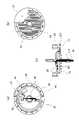
図2(a)はインホイールモータ11の分解斜視図である。インホイールモータ11の主要構成部品は、金属等で形成されたホイールケース21とホイールケース29とにより構成される筐体の内部に収められる。ホイールケース21は、その回転軸部分にシャフト112を通す穴が設けられており、周縁部が張り出した円盤形状を持つ。またその外側および内側の表面には、放熱用のフィン111が設けられている。フィン111は、本例では、互いに並列な複数の細長い張り出しであり、ホイールケース21と一体に成形されている。その高さや本数は、インホイールモータ11の内部で生じる熱を放出するために、その発熱量に応じて決定してよい。ホイールケース29は、ホイールケース21と同様の構成であるが、本例では外周部に設けた周縁部の張り出しがない。しかしホイールケース21と同様の構成としてもよい。ホイールケース21とホイールケース29とは、例えばボルトなどで互いに固定されてインホイールモータ11のケースを構成し、ベアリング22,28を介してシャフト112に取り付けられる。このため、ホイールケース21,29は、スイングアーム13に固定されて回転しないシャフト112に対して回転でき、その外周にタイヤ12が取り付けられて、駆動輪のハブともなる。● Configuration of the in-wheel motor FIG. 2A is an exploded perspective view of the in-
ホイールケース21の周縁部の張り出しの内側に沿って、ロータ23が連結或いは固定される。ロータ23は、例えば16個あるいは32個といった複数の永久磁石を、極性を交互に反転させつつ配置して構成されている。これは一般的なアウターロータ型のモータと同様である。一方シャフト112には、回路ケース26が固定される。回路ケース26は、シャフト112を中心とする、例えば金属製の円盤形状の部材である。回路ケース26のホイールケース29に対向する面の一部には、好ましくは回路ケース26と一体的に形成された放熱用のフィンが設けられている。また同じ面の一部には、ホールセンサを設けたホール素子基板27が取り付けられる。また回路ケース26のホール素子基板27と反対側の面には、PCU10を設けたPCU基板25が取り付けられる。PCU基板25とホール素子基板27とは、回路ケース26に穿った通し穴を通して必要な信号線及び電力線で繋げられている。回路ケース26のPCU基板25側の面には、本例ではフィンが設けられていないが、設けてもよい。 The
回路ケース26には、その周囲を取り巻くようにステータ24が取り付けられる。すなわち、ステータ24は、回路ケース26を介してシャフト112に対して固定されている。ステータ24にはインバータ102からからの三相交流電源UVWにそれぞれ接続された巻き線が含まれる。ステータ24はシャフト112に固定されており、その外側のロータ23が回転する。 A
図2(b)は、インホイールモータ11の回転軸に平行な断面を示す断面図である。シャフト112を軸として、ホイールケース21,29により構成された筐体内に、ロータ23、ステータ24、基板ケース26等が収容されている。ここで、基板ケース26は金属等の熱伝導性の高い熱伝導部材であり、基板類を取り付ける部材であるとともに、放熱板としても機能する。そのためPCU基板25は、そこに取り付けた発熱する部品が、直接、あるいは高い熱伝導率を持つ熱伝導素材を介して基板ケース26に接するように、基板ケース26に取り付けられてよい。さらにステータ24も基板ケース26に接触し、その熱が基板ケース26に伝播する。このような構成の結果、ステータ24やPCU基板25の熱は基板ケース26に伝達しやすい。また基板ケース26のフィンが設けられた側の面がホイールケース29に対向しており、ホイールケース29の回転によって、基板ケース26とホイールケース29との間の空間内に空気の流れを生じる。この空気流が、基板ケース26のフィンに接してそれを効果的に冷却する。逆にホール素子基板27は、基板ケース26に取り付けられるものの、基板ケース26からの熱がホール素子に伝播しにくいように取り付けられることが望ましい。 FIG. 2B is a cross-sectional view showing a cross section parallel to the rotation axis of the in-
図4にその様子を示す。図4は、図2(b)の断面のうち、基板ケース26とホイールケース29とについて、シャフト112から上部を示す。ホイールケース29が回転することで、ホイールケース29に沿って外周側へと向かう空気流が生じ、その空気流はホイールケース21の外縁に当たって基板ケース26側の空間へと向かう。その空気流は基板ケース26によりシャフト112側へと向けられ、シャフト112を挟んだ反対側でも生じている空気流と衝突して、図4に示す矢印のような渦上の対流を引き起こす。この空気の流れにより、PCU基板25やホール素子基板27、ステータ24等で生じて基板ケース26に伝達された熱は、さらにホイールケース29へと伝播される。そして、ホイールケース29の外側表面に設けたフィンから効果的に放熱される。ホイールケース21についても同様にこのような効果が生じ、内部で生じた熱をインホイールモータ11の外部へと効果的に放散できる。 FIG. 4 shows the situation. FIG. 4 shows the upper part of the
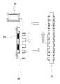
図3(a)~図3(c)に、基板ケース26に対するPCU基板25およびホール素子基板27の取り付けの詳細を示す。図3(a)は基板ケース26のPCU基板25側を、図3(b)はその反対のホール素子基板27側を、図3(c)は断面を示す。PCU基板25とホール素子基板27はそれぞれ、基板ケース26の対向する面の、互いに重ならない位置に取り付けられる。PCU基板25は、その上に設けたインバータ102のFET等のパワー素子251が、基板ケース26に直に接するように取り付けられる。これにより、パワー素子251からの熱が効率的に基板ケース26に伝播される。またホール素子基板27上のホール素子271は、ロータ23の回転位置を検知するために、ロータ側の端部に設けられている。基板ケース26はその外周部をステータ243により囲まれるように構成され、その中心部でシャフト112と結合されている。シャフト112は両端が開いた中空に形成されており、ホイールケース内部の、PCU基板25が取り付けられた面の側に通じる穴41,42が設けられている。二輪車1の本体に搭載された電源から導かれてシャフト112の端部から中空のシャフト内へと挿通された電源ケーブルやその他の制御信号などのケーブル(あるいはハーネス)40は、穴41,42を介してPCU基板25へと導かれ、所定の端子に接続される。PCU基板25とホール素子基板27とを接続するケーブルは、基板ケース26の開口43を通して配線される。このように、PCU基板25とホール素子基板27は、基板ケース26の互いに反対の面に取り付けられる。 3 (a) to 3 (c) show details of mounting the
このような構成によってPCU基板25とホール素子基板27との間の配線を簡単化でき、インホイールモータ11の構成をコンパクト化できる。さらに、インホイールモータ11内部への配線を中空のシャフト112を通して実現したことも、インホイールモータ11のコンパクト化に寄与する。またPCU基板25とホール素子基板27とは互いに重複しない位置に設けられているため、PCU基板25の、特にインバータ102により生じる熱によるホール素子回路27への影響を低減できる。 With such a configuration, the wiring between the
なお本実施形態では、ケースに設けたフィンは一定の方向に並列に配置されているが、これに限らない。たとえば、シャフトを中心とした放射状等に配列されてもよい。また直線的な形状のみならず、曲線的な形状であってもよい。また放熱の効率のみならず、風切り音等を考慮して形状を決定してもよい。 In the present embodiment, the fins provided in the case are arranged in parallel in a certain direction, but the present invention is not limited to this. For example, they may be arranged radially around the shaft. Further, not only a linear shape but also a curved shape may be used. Further, the shape may be determined in consideration of not only the efficiency of heat dissipation but also wind noise and the like.
なお本実施形態ではインホイールモータ11を動力として用いる車両を二輪車としたが、三輪車や四輪車であってもよい。また駆動輪は後輪に限らず前輪としてもよいし、車両が備える全ての車輪としてもよい。また二輪車であっても前後に車輪を備えているものに限らず、車椅子など進行方向に対して左右に並列な車輪を備えた車両であってもよい。その場合には両輪が駆動輪となり、インホイールモータ11により駆動される。またこのような二輪車や四輪車の場合には、インホイールモータ11はコントローラ101による制御で逆回転(すなわち後退)できるよう構成されていてもよい。さらに車両の駆動輪に限らず、対象を回転させるための動力源として本実施形態に係るインホイールモータ11を用いてもよい。さらに車両の駆動輪としてインホイールモータ11を用いる場合には、走行風を効率的に駆動輪のハブ部分に導くような部材を車両に取り付けてもよい。 In the present embodiment, the vehicle using the in-
●実施形態のまとめ
以上説明した本実施形態をまとめると以下のとおりである。
(1)本実施形態に係る第一の発明によれば、モータ(11)の構造であって、
ステータ(24)と、
前記ステータ(24)からの磁力によって回転するロータ(23)と、
前記ロータ(23)に連結された、前記モータのケース(21,29)と、
前記ステータ(24)に対して固定され、前記ケース(21,29)の内側に配置された板状の熱伝導部材(26)と、
前記熱伝導部材(26)の一方の面に取り付けた、前記ステータ(24)を駆動するための電力制御部(10)と、
前記熱伝導部材(26)の他方の面に取り付けた、前記ロータ(23)の回転位置を検知するセンサ(271)と
を有することを特徴とするモータの構造が提供される。● Summary of Embodiments The following is a summary of the present embodiments described above.
(1) According to the first invention according to the present embodiment, the structure is the motor (11).
With the stator (24),
The rotor (23) rotated by the magnetic force from the stator (24) and
The motor case (21, 29) connected to the rotor (23) and
A plate-shaped heat conductive member (26) fixed to the stator (24) and arranged inside the cases (21, 29), and
A power control unit (10) for driving the stator (24) attached to one surface of the heat conductive member (26).
Provided is a motor structure comprising a sensor (271) attached to the other surface of the heat conductive member (26) to detect the rotational position of the rotor (23).
それにより、電力制御部およびセンサを一枚の熱伝導部材に配置することができるので、モータ内部の構成を簡潔にするとともに、効率よくモータを冷却し、さらに熱によるセンサへの影響を軽減することができる。
(2)本実施形態に係る第二の発明によれば、(1)のモータ(11)の構造であって、
前記電力制御部(10)と前記センサ(271)は、前記熱伝導部材(26)を挟んで互いに重ならない位置に配置されたことを特徴とするモータの構造が提供される。As a result, the power control unit and the sensor can be arranged in one heat conductive member, so that the internal configuration of the motor can be simplified, the motor can be cooled efficiently, and the influence of heat on the sensor can be reduced. be able to.
(2) According to the second invention according to the present embodiment, it is the structure of the motor (11) of (1).
The motor structure is provided in which the power control unit (10) and the sensor (271) are arranged at positions that do not overlap each other with the heat conductive member (26) interposed therebetween.
それにより、より一層、電力制御部からセンサに対する熱の影響を低減させることができる。
(3)本実施形態に係る第三の発明によれば、(1)または(2)のモータ(11)の構造であって、
前記ステータ(24)に対して固定され、前記ロータ(23)と共に回転する前記ケース(21,29)の軸となる、前記ケース(21,29)に対して回動可能な中空のシャフト(112)を更に有し、
前記電力制御部(10)に接続されるハーネスが、前記シャフト(112)内を挿通して前記ケース(21,29)の内部へと配線されることを特徴とするモータの構造が提供される。As a result, the influence of heat on the sensor from the power control unit can be further reduced.
(3) According to the third invention according to the present embodiment, the structure of the motor (11) of (1) or (2).
A hollow shaft (112) that is fixed to the stator (24) and is rotatable with respect to the case (21, 29), which is the axis of the case (21, 29) that rotates with the rotor (23). ) Further
Provided is a motor structure characterized in that a harness connected to the power control unit (10) is routed through the shaft (112) and into the case (21, 29). ..
それにより、モータ内部における配線効率を向上させることができ、モータを小型化することが可能になる。
(4)本実施形態に係る第四の発明によれば、(1)乃至(3)のいずれかの構造を持つモータ(11)の前記ケース(21,29)の外周にタイヤ(12)を取り付けた駆動輪を有することを特徴とする車両が提供される。As a result, the wiring efficiency inside the motor can be improved, and the motor can be miniaturized.
(4) According to the fourth invention according to the present embodiment, the tire (12) is attached to the outer periphery of the case (21, 29) of the motor (11) having any of the structures (1) to (3). Vehicles are provided characterized by having mounted drive wheels.
それにより、ケースが車両の走行とともに回転し、空気の流れを起こしやすくなるため、冷却効率をより一層向上させることができる。 As a result, the case rotates as the vehicle travels, which makes it easier for air to flow, so that the cooling efficiency can be further improved.
本発明は上記実施の形態に制限されるものではなく、本発明の精神及び範囲から離脱することなく、様々な変更及び変形が可能である。 The present invention is not limited to the above embodiments, and various modifications and modifications can be made without departing from the spirit and scope of the present invention.
Claims (4)
Translated fromJapaneseステータ(24)と、
前記ステータ(24)からの磁力によって回転するロータ(23)と、
前記ロータ(23)に連結された、前記モータのケース(21,29)と、
前記ステータ(24)に対して固定され、前記ケース(21,29)の内側に配置された板状の熱伝導部材(26)と、
前記熱伝導部材(26)の一方の面に取り付けた、前記ステータ(24)を駆動するための電力制御部(10)と、
前記熱伝導部材(26)の他方の面に取り付けた、前記ロータ(23)の回転位置を検知するセンサ(271)と、
前記熱伝導部材(26)に固定され、前記熱伝導部材(26)を介して前記ステータ(24)に対して固定された、前記ロータ(23)と共に回転する前記ケース(21,29)の軸となる、前記ケース(21,29)に対して回動可能な中空のシャフト(112)と
を有することを特徴とするモータの構造。The structure of the motor (11)
With the stator (24),
The rotor (23) rotated by the magnetic force from the stator (24) and
The motor case (21, 29) connected to the rotor (23) and
A plate-shaped heat conductive member (26) fixed to the stator (24) and arranged inside the cases (21, 29), and
A power control unit (10) for driving the stator (24) attached to one surface of the heat conductive member (26).
A sensor (271) attached to the other surface of the heat conductive member (26) to detect the rotational position of the rotor (23), anda sensor (271).
The shaft of the case (21, 29) rotating with the rotor (23) fixed to the heat conductive member (26) and fixed to the stator (24) via the heat conductive member (26). With a hollow shaft (112) rotatable with respect to the case (21, 29).
The structure of the motor, characterized by having.
前記電力制御部(10)と前記センサ(271)は、前記熱伝導部材(26)を挟んで互いに重ならない位置に配置されたことを特徴とするモータの構造。The structure of the motor (11) according to claim 1.
The structure of the motor, wherein the power control unit (10) and the sensor (271) are arranged at positions where they do not overlap each other with the heat conductive member (26) interposed therebetween.
前記電力制御部(10)に接続されるハーネスが、前記シャフト(112)内を挿通して前記ケース(21,29)の内部へと配線されることを特徴とするモータの構造。The structure ofthe motor (11) according to claim 1 or 2.
A structure of a motor,wherein a harness connected to the power control unit (10) is inserted through the shaft (112) and wired into the case (21, 29).
Priority Applications (2)
| Application Number | Priority Date | Filing Date | Title |
|---|---|---|---|
| JP2018184943AJP7083298B2 (en) | 2018-09-28 | 2018-09-28 | Motor structure and vehicle |
| CN201910797064.1ACN110971086B (en) | 2018-09-28 | 2019-08-27 | Motor structure |
Applications Claiming Priority (1)
| Application Number | Priority Date | Filing Date | Title |
|---|---|---|---|
| JP2018184943AJP7083298B2 (en) | 2018-09-28 | 2018-09-28 | Motor structure and vehicle |
Publications (2)
| Publication Number | Publication Date |
|---|---|
| JP2020058088A JP2020058088A (en) | 2020-04-09 |
| JP7083298B2true JP7083298B2 (en) | 2022-06-10 |
Family
ID=70028458
Family Applications (1)
| Application Number | Title | Priority Date | Filing Date |
|---|---|---|---|
| JP2018184943AActiveJP7083298B2 (en) | 2018-09-28 | 2018-09-28 | Motor structure and vehicle |
Country Status (2)
| Country | Link |
|---|---|
| JP (1) | JP7083298B2 (en) |
| CN (1) | CN110971086B (en) |
Cited By (3)
| Publication number | Priority date | Publication date | Assignee | Title |
|---|---|---|---|---|
| EP4611228A1 (en) | 2024-03-01 | 2025-09-03 | Mazda Motor Corporation | Vehicle drive system |
| EP4611229A1 (en) | 2024-03-01 | 2025-09-03 | Mazda Motor Corporation | Vehicle drive system |
| EP4611230A1 (en) | 2024-03-01 | 2025-09-03 | Mazda Motor Corporation | Vehicle drive system |
Families Citing this family (2)
| Publication number | Priority date | Publication date | Assignee | Title |
|---|---|---|---|---|
| EP4291489A1 (en)* | 2021-02-09 | 2023-12-20 | Joby Aero, Inc. | Aircraft propulsion unit |
| WO2025143037A1 (en)* | 2023-12-28 | 2025-07-03 | 株式会社小糸製作所 | Vehicle headlamp |
Citations (2)
| Publication number | Priority date | Publication date | Assignee | Title |
|---|---|---|---|---|
| JP2016530871A (en) | 2013-09-10 | 2016-09-29 | プロティアン エレクトリック リミテッドProtean Electric Limited | Electric motor or generator |
| JP2017185975A (en) | 2016-04-08 | 2017-10-12 | ミネベアミツミ株式会社 | Motor, in-wheel motor and wheel device |
Family Cites Families (29)
| Publication number | Priority date | Publication date | Assignee | Title |
|---|---|---|---|---|
| DE2146893C3 (en)* | 1971-09-20 | 1974-02-07 | Siemens Ag, 1000 Berlin U. 8000 Muenchen | Brushless DC motor with a commutation device controlled by Hall generators and made up of semiconductor switching elements |
| US6034465A (en)* | 1997-08-06 | 2000-03-07 | Shurfle Pump Manufacturing Co. | Pump driven by brushless motor |
| US7199496B2 (en)* | 2005-01-18 | 2007-04-03 | Oriental Motor Boston Technology Group Incorporated | Integrated electric motor and drive, optimized for high-temperature operation |
| CN101282071A (en)* | 2008-05-26 | 2008-10-08 | 湘潭电机股份有限公司 | Permanent magnetism synchronous wheel hub motor for directly driving electric vehicle wheel |
| DE102009014595A1 (en)* | 2009-03-24 | 2010-09-30 | Magna Powertrain Ag & Co Kg | gear unit |
| CN201478969U (en)* | 2009-04-30 | 2010-05-19 | 浙江关西电机有限公司 | Integrated hub motor |
| JP5586707B2 (en)* | 2010-12-07 | 2014-09-10 | 三菱電機株式会社 | Motor with built-in power conversion circuit, fluid pump with this motor with built-in power conversion circuit, air conditioner with this fluid pump, water heater, equipment with motor with built-in power conversion circuit |
| JP5807846B2 (en)* | 2012-03-29 | 2015-11-10 | 株式会社デンソー | Drive device |
| US8946954B2 (en)* | 2012-04-20 | 2015-02-03 | Nidec Motor Corporation | Integrated direct drive motor and control |
| US9450471B2 (en)* | 2012-05-24 | 2016-09-20 | Milwaukee Electric Tool Corporation | Brushless DC motor power tool with combined PCB design |
| CN102801253A (en)* | 2012-08-20 | 2012-11-28 | 常州新亚电机有限公司 | Motor and controller assembly |
| JP5862645B2 (en)* | 2013-11-29 | 2016-02-16 | 株式会社デンソー | Drive device |
| CN104716781A (en)* | 2013-12-12 | 2015-06-17 | 日本电产株式会社 | Motor |
| WO2015122069A1 (en)* | 2014-02-14 | 2015-08-20 | 三菱電機株式会社 | Control-device-equipped rotating electrical machine, electric power steering device, and production method for control-device-equipped rotating electrical machine |
| FR3019951B1 (en)* | 2014-04-11 | 2016-04-29 | Valeo Systemes Thermiques | ELECTRIC MOTOR, AIR PULSE DEVICE AND HEATING AND / OR AIR CONDITIONING VENTILATION SYSTEM EQUIPPED WITH SUCH ENGINE |
| JP6172217B2 (en)* | 2014-07-31 | 2017-08-02 | 株式会社デンソー | DRIVE DEVICE AND ELECTRIC POWER STEERING DEVICE USING THE SAME |
| JP2016082669A (en)* | 2014-10-15 | 2016-05-16 | 日本電産株式会社 | Motor for ceiling fan, and ceiling fan |
| CN105896811A (en)* | 2014-12-17 | 2016-08-24 | 张仲安 | Directly-driven wheel hub motor |
| JP2016123237A (en)* | 2014-12-25 | 2016-07-07 | 株式会社ジェイテクト | Motor unit |
| CN204442094U (en)* | 2014-12-31 | 2015-07-01 | 上海德愚新能源科技有限公司 | A kind of Hall Split type heat radiation electric wheel shell motor |
| JP2016140147A (en)* | 2015-01-26 | 2016-08-04 | 株式会社デンソー | Rotary electric machine |
| JP6408926B2 (en)* | 2015-02-05 | 2018-10-17 | 日立オートモティブシステムズ株式会社 | Electric drive device and electric power steering device |
| EP3257138B1 (en)* | 2015-02-13 | 2019-12-04 | Electric Vehicle Systems And Technology Pty Ltd | Electric motor |
| JP6648492B2 (en)* | 2015-11-04 | 2020-02-14 | 株式会社デンソー | Electronic equipment |
| JP6514135B2 (en)* | 2016-03-09 | 2019-05-15 | 日立オートモティブシステムズ株式会社 | Electric drive device and electric power steering device |
| CN106208545B (en)* | 2016-09-13 | 2018-05-15 | 彭希南 | Amorphous alloy core body permanent-magnet brushless DC electric machine |
| CN206432854U (en)* | 2016-11-25 | 2017-08-22 | 上海擎朗智能科技有限公司 | A kind of wheel hub motor |
| JP2018125940A (en)* | 2017-01-31 | 2018-08-09 | 株式会社デンソー | Driving device |
| CN207638448U (en)* | 2017-12-15 | 2018-07-20 | 中华汽车工业股份有限公司 | Vehicle motor with built-in charging control function |
- 2018
- 2018-09-28JPJP2018184943Apatent/JP7083298B2/enactiveActive
- 2019
- 2019-08-27CNCN201910797064.1Apatent/CN110971086B/enactiveActive
Patent Citations (2)
| Publication number | Priority date | Publication date | Assignee | Title |
|---|---|---|---|---|
| JP2016530871A (en) | 2013-09-10 | 2016-09-29 | プロティアン エレクトリック リミテッドProtean Electric Limited | Electric motor or generator |
| JP2017185975A (en) | 2016-04-08 | 2017-10-12 | ミネベアミツミ株式会社 | Motor, in-wheel motor and wheel device |
Cited By (3)
| Publication number | Priority date | Publication date | Assignee | Title |
|---|---|---|---|---|
| EP4611228A1 (en) | 2024-03-01 | 2025-09-03 | Mazda Motor Corporation | Vehicle drive system |
| EP4611229A1 (en) | 2024-03-01 | 2025-09-03 | Mazda Motor Corporation | Vehicle drive system |
| EP4611230A1 (en) | 2024-03-01 | 2025-09-03 | Mazda Motor Corporation | Vehicle drive system |
Also Published As
| Publication number | Publication date |
|---|---|
| CN110971086A (en) | 2020-04-07 |
| CN110971086B (en) | 2022-04-01 |
| JP2020058088A (en) | 2020-04-09 |
Similar Documents
| Publication | Publication Date | Title |
|---|---|---|
| JP7083298B2 (en) | Motor structure and vehicle | |
| JP5039171B2 (en) | Electric drive device and electric power steering device equipped with the electric drive device | |
| JP4859950B2 (en) | Rotating electric machine | |
| JP5147943B2 (en) | Electric power steering device and control device integrated motor | |
| JP5970668B2 (en) | Power module for electric power steering and electric power steering drive control apparatus using the same | |
| JP4275614B2 (en) | Rotating electric machine for vehicles | |
| CN100537288C (en) | Electric power units, electric vehicles and electric two-wheelers | |
| CN1913297B (en) | Rotating electric machine for vehicles | |
| JP6324946B2 (en) | Brushless wiper motor | |
| JP7156892B2 (en) | Motor structure | |
| JP4339832B2 (en) | Rotating electric machine for vehicles | |
| CN108290603A (en) | Electric drives and electric power steering | |
| JP5796301B2 (en) | Motor and electric power steering device | |
| JP2006333587A (en) | Motor system | |
| JP2017131058A (en) | Motor, and, electric power steering device using the same | |
| KR101719631B1 (en) | Fan and Shroud Assemble | |
| JP2017143595A (en) | Brushless motor | |
| CN118160205A (en) | Rotating motor device and electric power steering device | |
| JP5848400B2 (en) | Wheel-in motor and electric vehicle | |
| US20220399781A1 (en) | Motor module and electric powered tool using the same | |
| TW202139586A (en) | Motor structure |
Legal Events
| Date | Code | Title | Description |
|---|---|---|---|
| A621 | Written request for application examination | Free format text:JAPANESE INTERMEDIATE CODE: A621 Effective date:20201130 | |
| RD02 | Notification of acceptance of power of attorney | Free format text:JAPANESE INTERMEDIATE CODE: A7422 Effective date:20210103 | |
| A521 | Request for written amendment filed | Free format text:JAPANESE INTERMEDIATE CODE: A523 Effective date:20210125 | |
| A977 | Report on retrieval | Free format text:JAPANESE INTERMEDIATE CODE: A971007 Effective date:20211022 | |
| A131 | Notification of reasons for refusal | Free format text:JAPANESE INTERMEDIATE CODE: A131 Effective date:20211112 | |
| A521 | Request for written amendment filed | Free format text:JAPANESE INTERMEDIATE CODE: A523 Effective date:20211228 | |
| TRDD | Decision of grant or rejection written | ||
| A01 | Written decision to grant a patent or to grant a registration (utility model) | Free format text:JAPANESE INTERMEDIATE CODE: A01 Effective date:20220509 | |
| A61 | First payment of annual fees (during grant procedure) | Free format text:JAPANESE INTERMEDIATE CODE: A61 Effective date:20220531 | |
| R150 | Certificate of patent or registration of utility model | Ref document number:7083298 Country of ref document:JP Free format text:JAPANESE INTERMEDIATE CODE: R150 |