JP7080766B2 - Sensor target cover used in combination with liquid level detection sensor, and wet processing equipment - Google Patents
Sensor target cover used in combination with liquid level detection sensor, and wet processing equipmentDownload PDFInfo
- Publication number
- JP7080766B2 JP7080766B2JP2018148638AJP2018148638AJP7080766B2JP 7080766 B2JP7080766 B2JP 7080766B2JP 2018148638 AJP2018148638 AJP 2018148638AJP 2018148638 AJP2018148638 AJP 2018148638AJP 7080766 B2JP7080766 B2JP 7080766B2
- Authority
- JP
- Japan
- Prior art keywords
- substrate
- wall structure
- wall
- liquid level
- target cover
- Prior art date
- Legal status (The legal status is an assumption and is not a legal conclusion. Google has not performed a legal analysis and makes no representation as to the accuracy of the status listed.)
- Active
Links
- 239000007788liquidSubstances0.000titleclaimsdescription144
- 238000012545processingMethods0.000titleclaimsdescription112
- 238000001514detection methodMethods0.000titleclaimsdescription51
- 239000000758substrateSubstances0.000claimsdescription182
- 238000004140cleaningMethods0.000claimsdescription113
- 238000005498polishingMethods0.000claimsdescription97
- 230000003287optical effectEffects0.000claimsdescription49
- 230000001681protective effectEffects0.000claimsdescription39
- 238000012546transferMethods0.000description49
- 238000001035dryingMethods0.000description27
- 230000032258transportEffects0.000description26
- 125000006850spacer groupChemical group0.000description18
- XLYOFNOQVPJJNP-UHFFFAOYSA-NwaterSubstancesOXLYOFNOQVPJJNP-UHFFFAOYSA-N0.000description13
- 238000009833condensationMethods0.000description11
- 230000005494condensationEffects0.000description11
- 239000000126substanceSubstances0.000description8
- 239000000243solutionSubstances0.000description7
- 230000003028elevating effectEffects0.000description6
- 238000002474experimental methodMethods0.000description6
- 230000002093peripheral effectEffects0.000description6
- 230000007423decreaseEffects0.000description4
- 230000007246mechanismEffects0.000description4
- 230000000630rising effectEffects0.000description4
- 239000002002slurrySubstances0.000description4
- KFZMGEQAYNKOFK-UHFFFAOYSA-NIsopropanolChemical compoundCC(C)OKFZMGEQAYNKOFK-UHFFFAOYSA-N0.000description3
- 238000010586diagramMethods0.000description3
- 230000009471actionEffects0.000description2
- 239000012530fluidSubstances0.000description2
- 239000007789gasSubstances0.000description2
- 238000005192partitionMethods0.000description2
- 230000035699permeabilityEffects0.000description2
- 239000004925Acrylic resinSubstances0.000description1
- 229920000178Acrylic resinPolymers0.000description1
- IJGRMHOSHXDMSA-UHFFFAOYSA-NAtomic nitrogenChemical compoundN#NIJGRMHOSHXDMSA-UHFFFAOYSA-N0.000description1
- 239000006061abrasive grainSubstances0.000description1
- 230000003749cleanlinessEffects0.000description1
- 230000001143conditioned effectEffects0.000description1
- 238000011109contaminationMethods0.000description1
- 229910001873dinitrogenInorganic materials0.000description1
- 239000000428dustSubstances0.000description1
- 238000000034methodMethods0.000description1
- 239000000203mixtureSubstances0.000description1
- 238000012986modificationMethods0.000description1
- 230000004048modificationEffects0.000description1
- 239000002245particleSubstances0.000description1
- 230000008569processEffects0.000description1
- 239000011347resinSubstances0.000description1
- 229920005989resinPolymers0.000description1
- 239000012487rinsing solutionSubstances0.000description1
Images


Classifications
- B—PERFORMING OPERATIONS; TRANSPORTING
- B08—CLEANING
- B08B—CLEANING IN GENERAL; PREVENTION OF FOULING IN GENERAL
- B08B3/00—Cleaning by methods involving the use or presence of liquid or steam
- B08B3/02—Cleaning by the force of jets or sprays
- B—PERFORMING OPERATIONS; TRANSPORTING
- B08—CLEANING
- B08B—CLEANING IN GENERAL; PREVENTION OF FOULING IN GENERAL
- B08B3/00—Cleaning by methods involving the use or presence of liquid or steam
- B08B3/04—Cleaning involving contact with liquid
- B—PERFORMING OPERATIONS; TRANSPORTING
- B24—GRINDING; POLISHING
- B24B—MACHINES, DEVICES, OR PROCESSES FOR GRINDING OR POLISHING; DRESSING OR CONDITIONING OF ABRADING SURFACES; FEEDING OF GRINDING, POLISHING, OR LAPPING AGENTS
- B24B37/00—Lapping machines or devices; Accessories
- B24B37/005—Control means for lapping machines or devices
- B—PERFORMING OPERATIONS; TRANSPORTING
- B24—GRINDING; POLISHING
- B24B—MACHINES, DEVICES, OR PROCESSES FOR GRINDING OR POLISHING; DRESSING OR CONDITIONING OF ABRADING SURFACES; FEEDING OF GRINDING, POLISHING, OR LAPPING AGENTS
- B24B37/00—Lapping machines or devices; Accessories
- B24B37/34—Accessories
- G—PHYSICS
- G01—MEASURING; TESTING
- G01F—MEASURING VOLUME, VOLUME FLOW, MASS FLOW OR LIQUID LEVEL; METERING BY VOLUME
- G01F23/00—Indicating or measuring liquid level or level of fluent solid material, e.g. indicating in terms of volume or indicating by means of an alarm
- G01F23/22—Indicating or measuring liquid level or level of fluent solid material, e.g. indicating in terms of volume or indicating by means of an alarm by measuring physical variables, other than linear dimensions, pressure or weight, dependent on the level to be measured, e.g. by difference of heat transfer of steam or water
- G01F23/28—Indicating or measuring liquid level or level of fluent solid material, e.g. indicating in terms of volume or indicating by means of an alarm by measuring physical variables, other than linear dimensions, pressure or weight, dependent on the level to be measured, e.g. by difference of heat transfer of steam or water by measuring the variations of parameters of electromagnetic or acoustic waves applied directly to the liquid or fluent solid material
- G01F23/284—Electromagnetic waves
- G01F23/292—Light, e.g. infrared or ultraviolet
- G01F23/2921—Light, e.g. infrared or ultraviolet for discrete levels
Landscapes
- Physics & Mathematics (AREA)
- Electromagnetism (AREA)
- Engineering & Computer Science (AREA)
- Mechanical Engineering (AREA)
- Thermal Sciences (AREA)
- Fluid Mechanics (AREA)
- General Physics & Mathematics (AREA)
- Cleaning Or Drying Semiconductors (AREA)
- Measurement Of Levels Of Liquids Or Fluent Solid Materials (AREA)
- Mechanical Treatment Of Semiconductor (AREA)
Description
Translated fromJapanese本発明は、基板洗浄装置やバフ研磨装置などの湿式処理装置の液面検出センサと組み合わせて使用されるセンサターゲットカバーに関する。また、本発明は、そのようなセンサターゲットカバーおよび光学式液面検出センサを備えた湿式処理装置に関する。 The present invention relates to a sensor target cover used in combination with a liquid level detection sensor of a wet processing device such as a substrate cleaning device or a buffing device. The present invention also relates to a wet processing apparatus including such a sensor target cover and an optical liquid level detection sensor.
化学機械研磨(CMP)装置では、ウェーハなどの基板を研磨した後に基板が洗浄される。CMP装置は、一般に、基板を化学機械的に研磨するCMPユニットと、研磨された基板を洗浄するための洗浄ユニットを備えている。洗浄ユニットは、基板に薬液またはリンス液などの液体を供給しながら、基板にロールスポンジやペンスポンジなどの洗浄具を摺接させることで、基板の表面および裏面を洗浄する。 In a chemical mechanical polishing (CMP) apparatus, a substrate such as a wafer is polished and then the substrate is cleaned. A CMP device generally includes a CMP unit for chemically and mechanically polishing a substrate and a cleaning unit for cleaning the polished substrate. The cleaning unit cleans the front surface and the back surface of the substrate by sliding a cleaning tool such as a roll sponge or a pen sponge on the substrate while supplying a liquid such as a chemical solution or a rinsing solution to the substrate.
このような洗浄ユニットには、液体を排出するためのドレインポートが設けられている。基板の洗浄に使用された液体は、ドレインポートを通って排出される。しかしながら、ドレインポートが基板の破片などのごみで詰まってしまうと、液体は洗浄ユニットから排出されず、洗浄ユニット内に溜まってしまう。その結果、洗浄ユニット内に配置された洗浄具や、洗浄具を回転させるためのモータが液体に浸漬してしまう。 Such a cleaning unit is provided with a drain port for draining the liquid. The liquid used to clean the substrate is drained through the drain port. However, if the drain port is clogged with debris such as substrate debris, the liquid will not be discharged from the cleaning unit and will accumulate in the cleaning unit. As a result, the cleaning tool arranged in the cleaning unit and the motor for rotating the cleaning tool are immersed in the liquid.
そこで、洗浄ユニットは、洗浄ユニット内の液面を検出する光学式液面検出センサを備えている。この光学式液面検出センサは、洗浄ユニット内に配置された反射板に向けて光を放ち、反射板から反射した光量を測定するように構成されている。液面が上昇していないとき、光学式液面検出センサは反射板からの反射光を受け取ることができるが、液面が上昇して反射板が液体中に没すると、空気と液体とでは屈折率が異なるため、光学式液面検出センサは反射板からの反射光を受け取ることができない。結果として、光学式液面検出センサによって測定される光量が低下する。光量の測定値は、信号処理部によってしきい値と比較され、光量の測定値がしきい値よりも低下したとき、信号処理部は洗浄ユニット内の液面の上昇を検出する。 Therefore, the cleaning unit is provided with an optical liquid level detection sensor that detects the liquid level in the cleaning unit. This optical liquid level detection sensor is configured to emit light toward a reflector arranged in the cleaning unit and measure the amount of light reflected from the reflector. When the liquid level is not rising, the optical liquid level detection sensor can receive the reflected light from the reflector, but when the liquid level rises and the reflector is submerged in the liquid, the air and the liquid are refracted. Due to the different rates, the optical liquid level detection sensor cannot receive the reflected light from the reflector. As a result, the amount of light measured by the optical liquid level detection sensor is reduced. The measured value of the amount of light is compared with the threshold value by the signal processing unit, and when the measured value of the amount of light falls below the threshold value, the signal processing unit detects an increase in the liquid level in the cleaning unit.
しかしながら、液面が上昇していないときに反射板に液体が付着したり、あるいは反射板が結露すると、光の反射の仕方が変わり、光学式液面検出センサによって測定される光量が低下することがある。結果として、信号処理部は液面の上昇を正しく検出することができない場合があった。 However, if liquid adheres to the reflector or dew condensation occurs when the liquid level is not rising, the way light is reflected changes and the amount of light measured by the optical liquid level detection sensor decreases. There is. As a result, the signal processor may not be able to correctly detect the rise in the liquid level.
そこで、本発明は、光学式液面検出センサが液面の上昇を誤検出するのを防止することができるセンサターゲットカバーを提供することを目的とする。また、本発明は、そのようなセンサターゲットカバーおよび光学式液面検出センサを備えた湿式処理装置を提供することを目的とする。 Therefore, an object of the present invention is to provide a sensor target cover capable of preventing an optical liquid level detection sensor from erroneously detecting a rise in the liquid level. Another object of the present invention is to provide a wet processing apparatus including such a sensor target cover and an optical liquid level detection sensor.
一態様では、光学式液面検出センサと組み合わせて使用されるセンサターゲットカバーであって、反射板と、前記反射板を囲む内壁構造体と、前記内壁構造体を囲む外壁構造体とを備え、前記内壁構造体と前記外壁構造体との間には隙間が形成されているセンサターゲットカバーが提供される。 In one aspect, it is a sensor target cover used in combination with an optical liquid level detection sensor, comprising a reflector, an inner wall structure surrounding the reflector, and an outer wall structure surrounding the inner wall structure. A sensor target cover having a gap formed between the inner wall structure and the outer wall structure is provided.
一態様では、前記外壁構造体の下端は、前記内壁構造体の下端よりも高い位置にあり、前記外壁構造体の上端は、前記内壁構造体の上端よりも高い位置にある。
一態様では、前記内壁構造体の内部空間は、前記反射板によって第1の部屋と第2の部屋に仕切られている。
一態様では、前記内壁構造体は、前記反射板に対向する内保護壁と、前記反射板および前記内保護壁の両側に配置された2つの内側壁とを備える。
一態様では、前記外壁構造体は、前記2つの内側壁の外側にそれぞれ配置された2つの外側壁と、前記内保護壁の外側に配置された外保護壁と、天井壁とを備える。
一態様では、前記2つの内側壁の外面と前記2つの外側壁の内面との間にはそれぞれ隙間が形成されており、前記内保護壁の外面と前記外保護壁の内面との間には隙間が形成されており、前記2つの内側壁および前記内保護壁のそれぞれの上端と前記天井壁の下面との間には隙間が形成されている。In one aspect, the lower end of the outer wall structure is higher than the lower end of the inner wall structure, and the upper end of the outer wall structure is higher than the upper end of the inner wall structure.
In one aspect, the internal space of the inner wall structure is divided into a first room and a second room by the reflector.
In one aspect, the inner wall structure comprises an inner protective wall facing the reflector and two inner sidewalls disposed on both sides of the reflector and the inner protective wall.
In one aspect, the outer wall structure comprises two outer walls arranged on the outside of the two inner side walls, an outer protective wall arranged on the outside of the inner protective wall, and a ceiling wall.
In one aspect, a gap is formed between the outer surface of the two inner side walls and the inner surface of the two outer walls, respectively, and between the outer surface of the inner protective wall and the inner surface of the outer protective wall. A gap is formed, and a gap is formed between the upper ends of the two inner side walls and the inner protective wall and the lower surface of the ceiling wall.
一態様では、処理槽と、前記処理槽内に配置された基板保持部と、前記処理槽に配置されたドレインポートと、前記処理槽内に配置された液体供給ノズルと、前記処理槽内の液面を検出する光学式液面検出センサと、前記光学式液面検出センサに対面する上記センサターゲットカバーを備える湿式処理装置が提供される。 In one aspect, the treatment tank, the substrate holding portion arranged in the treatment tank, the drain port arranged in the treatment tank, the liquid supply nozzle arranged in the treatment tank, and the inside of the treatment tank. A wet processing apparatus including an optical liquid level detection sensor for detecting a liquid level and the sensor target cover facing the optical liquid level detection sensor is provided.
一態様では、前記センサターゲットカバーの下端と、前記処理槽の底部との間には隙間が形成されている。
一態様では、湿式処理装置は、前記処理槽内に配置された排気ポートをさらに備える。
一態様では、湿式処理装置は、前記処理槽の基板入口および基板出口よりも高い位置に配置されたクリーンエア供給装置をさらに備える。In one aspect, a gap is formed between the lower end of the sensor target cover and the bottom of the processing tank.
In one aspect, the wet treatment apparatus further comprises an exhaust port disposed within the treatment tank.
In one aspect, the wet treatment device further comprises a clean air supply device located higher than the substrate inlet and substrate outlet of the treatment tank.
一態様では、基板を研磨する研磨部と、研磨された基板を洗浄する複数の上記湿式処理装置を備えた洗浄部と、研磨された基板を前記研磨部から前記洗浄部へと搬送する搬送装置を備える、基板処理装置が提供される。 In one aspect, a polishing unit for polishing a substrate, a cleaning unit provided with a plurality of the wet processing devices for cleaning the polished substrate, and a transport device for transporting the polished substrate from the polishing unit to the cleaning unit. A substrate processing apparatus is provided.
反射板は内壁構造体によって囲まれ、内壁構造体は外壁構造体によって囲まれている。したがって、内壁構造体および外壁構造体は、液体の反射板への付着を防止することができる。さらに、内壁構造体と内壁構造体との間には隙間が形成されているので、センサターゲットカバー内に空気の流れが形成される。この空気の流れは、センサターゲットカバー内の反射板での結露を防止することができる。通常、処理槽の内部は、モータなどの発熱源および基板の処理に使用される液体の存在に起因して、高温多湿の状態となる。このような高温多湿の環境下でも、上述したセンサターゲットカバーは、通気性がよいので、その内部に配置された反射板での結露を防止することができる。したがって、光学式液面検出センサは、処理槽内の液面を正確に検出することができる。 The reflector is surrounded by an inner wall structure, and the inner wall structure is surrounded by an outer wall structure. Therefore, the inner wall structure and the outer wall structure can prevent the liquid from adhering to the reflector. Further, since a gap is formed between the inner wall structure and the inner wall structure, an air flow is formed in the sensor target cover. This air flow can prevent dew condensation on the reflector inside the sensor target cover. Normally, the inside of the processing tank is in a hot and humid state due to the presence of a heat generating source such as a motor and the liquid used for processing the substrate. Even in such a hot and humid environment, the sensor target cover described above has good air permeability, so that it is possible to prevent dew condensation on the reflector arranged inside the sensor target cover. Therefore, the optical liquid level detection sensor can accurately detect the liquid level in the processing tank.
以下、本発明の実施形態について図面を参照して説明する。
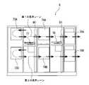
図1は、ウェーハなどの基板を研磨し、研磨された基板を洗浄し、洗浄された基板を乾燥するための基板処理装置の一実施形態の概略図である。図1に示すように、この基板処理装置は、略矩形状のハウジング1を備えており、ハウジング1の内部は隔壁1a,1bによってロード/アンロード部2と研磨部3と洗浄部4とに区画されている。基板処理装置は、基板処理動作を制御する動作制御部5を有している。Hereinafter, embodiments of the present invention will be described with reference to the drawings.
FIG. 1 is a schematic view of an embodiment of a substrate processing apparatus for polishing a substrate such as a wafer, cleaning the polished substrate, and drying the cleaned substrate. As shown in FIG. 1, this substrate processing apparatus includes a substantially rectangular housing 1, and the inside of the housing 1 is divided into a load /
ロード/アンロード部2は、多数の基板(例えばウェーハ)を収納する基板カセットが載置されるフロントロード部20を備えている。ロード/アンロード部2には、フロントロード部20の並びに沿ってレール機構21が敷設されており、このレール機構21上に基板カセットの配列方向に沿って移動可能な搬送ロボット(ローダー)22が設置されている。搬送ロボット22はレール機構21上を移動することによって、フロントロード部20に搭載された基板カセットにアクセスできるようになっている。さらに搬送ロボット22は上昇および下降ができるように構成されている。 The load /
研磨部3は、複数の基板を並列に研磨することができる複数の研磨ユニットを有する。本実施形態の研磨部3は、第1研磨ユニット3A、第2研磨ユニット3B、第3研磨ユニット3C、第4研磨ユニット3Dを備えている。ただし、研磨ユニットの数は本実施形態に限定されない。 The polishing unit 3 has a plurality of polishing units capable of polishing a plurality of substrates in parallel. The polishing unit 3 of the present embodiment includes a
図1に示すように、第1研磨ユニット3Aは、研磨面を有する研磨パッド10が取り付けられた第1研磨テーブル30Aと、基板を研磨テーブル30A上の研磨パッド10に押圧し、研磨するための第1研磨ヘッド31Aと、研磨パッド10に研磨液(例えばスラリー)やドレッシング液(例えば、純水)を供給するための第1液体供給ノズル32Aと、研磨パッド10の研磨面のドレッシングを行うための第1ドレッサ33Aと、液体(例えば純水)と気体(例えば窒素ガス)の混合流体を霧状にして研磨パッド10の研磨面に噴射する第1アトマイザ34Aを備えている。 As shown in FIG. 1, the
同様に、第2研磨ユニット3Bは、研磨パッド10が取り付けられた第2研磨テーブル30Bと、第2研磨ヘッド31Bと、第2液体供給ノズル32Bと、第2ドレッサ33Bと、第2アトマイザ34Bとを備えており、第3研磨ユニット3Cは、研磨パッド10が取り付けられた第3研磨テーブル30Cと、第3研磨ヘッド31Cと、第3液体供給ノズル32Cと、第3ドレッサ33Cと、第3アトマイザ34Cとを備えており、第4研磨ユニット3Dは、研磨パッド10が取り付けられた第4研磨テーブル30Dと、第4研磨ヘッド31Dと、第4液体供給ノズル32Dと、第4ドレッサ33Dと、第4アトマイザ34Dとを備えている。 Similarly, the
第1研磨ユニット3A、第2研磨ユニット3B、第3研磨ユニット3C、および第4研磨ユニット3Dは、同一の構成を有している。第1研磨ユニット3Aでは、基板の研磨は次のようにして行われる。研磨ヘッド31Aおよび研磨テーブル30Aをそれぞれ回転させ、液体供給ノズル32Aから研磨パッド10上に研磨液(スラリー)を供給する。この状態で、研磨ヘッド31Aは、基板を研磨パッド10の研磨面に押し付ける。基板の表面は、研磨液の化学的作用と研磨液に含まれる砥粒の機械的作用により研磨される。研磨終了後は、ドレッサ33Aによる研磨面のドレッシング(コンディショニング)が行われ、さらにアトマイザ34Aから高圧の流体が研磨面に供給されて、研磨面に残留する研磨屑およびスラリーが除去される。第2研磨ユニット3B、第3研磨ユニット3C、および第4研磨ユニット3Dでも、同様にして基板の研磨が行われる。 The
第1研磨ユニット3Aおよび第2研磨ユニット3Bに隣接して、第1リニアトランスポータ6が配置されている。この第1リニアトランスポータ6は、4つの搬送位置(第1搬送位置TP1、第2搬送位置TP2、第3搬送位置TP3、第4搬送位置TP4)の間で基板を搬送する搬送装置である。また、第3研磨ユニット3Cおよび第4研磨ユニット3Dに隣接して、第2リニアトランスポータ7が配置されている。この第2リニアトランスポータ7は、3つの搬送位置(第5搬送位置TP5、第6搬送位置TP6、第7搬送位置TP7)の間で基板を搬送する搬送装置である。 A first
基板は、第1リニアトランスポータ6によって第1研磨ユニット3Aおよび/または第2研磨ユニット3Bに搬送される。第1研磨ユニット3Aの研磨ヘッド31Aは、そのスイング動作により研磨テーブル30Aの上方位置と第2搬送位置TP2との間を移動する。したがって、研磨ヘッド31Aと第1リニアトランスポータ6との間での基板の受け渡しは第2搬送位置TP2で行われる。 The substrate is conveyed to the
同様に、第2研磨ユニット3Bの研磨ヘッド31Bは研磨テーブル30Bの上方位置と第3搬送位置TP3との間を移動し、研磨ヘッド31Bと第1リニアトランスポータ6との間での基板の受け渡しは第3搬送位置TP3で行われる。第3研磨ユニット3Cの研磨ヘッド31Cは研磨テーブル30Cの上方位置と第6搬送位置TP6との間を移動し、研磨ヘッド31Cと第2リニアトランスポータ7との間での基板の受け渡しは第6搬送位置TP6で行われる。第4研磨ユニット3Dの研磨ヘッド31Dは研磨テーブル30Dの上方位置と第7搬送位置TP7との間を移動し、研磨ヘッド31Dと第2リニアトランスポータ7との間での基板の受け渡しは第7搬送位置TP7で行われる。 Similarly, the polishing
第1搬送位置TP1には、搬送ロボット22から基板を受け取るためのリフタ11が配置されている。リフタ11は搬送ロボット22と第1リニアトランスポータ6との間に配置されている。基板はこのリフタ11を介して搬送ロボット22から第1リニアトランスポータ6に渡される。リフタ11と搬送ロボット22との間に位置して、シャッタ(図示せず)が隔壁1aに設けられており、基板の搬送時にはシャッタが開かれて搬送ロボット22からリフタ11に基板が渡されるようになっている。 At the first transfer position TP1, a
第1リニアトランスポータ6と、第2リニアトランスポータ7と、洗浄部4との間には、基板を搬送するための搬送装置であるスイングトランスポータ12が配置されている。第1リニアトランスポータ6から第2リニアトランスポータ7への基板の搬送は、スイングトランスポータ12によって行われる。基板は、第2リニアトランスポータ7によって第3研磨ユニット3Cおよび/または第4研磨ユニット3Dに搬送される。 A
スイングトランスポータ12の側方には、図示しないフレームに設置された基板の仮置きステージ72が配置されている。この仮置きステージ72は、第1リニアトランスポータ6に隣接して配置されており、第1リニアトランスポータ6と洗浄部4との間に位置している。スイングトランスポータ12は、第4搬送位置TP4、第5搬送位置TP5、および仮置きステージ72の間で基板を搬送する。 On the side of the
洗浄部4は、研磨された基板を洗浄する第1洗浄ユニット73A,73Bおよび第2洗浄ユニット74A,74Bと、洗浄された基板を乾燥する乾燥ユニット75A,75Bを備えている。第1洗浄ユニット73Aは第1洗浄ユニット73Bの上方に配置されており、第2洗浄ユニット74Aは第2洗浄ユニット74Bの上方に配置されている。乾燥ユニット75Aは乾燥ユニット75Bの上方に配置されている。 The
洗浄部4は、基板を搬送するための搬送装置として第1搬送ロボット77および第2搬送ロボット78をさらに備えている。仮置きステージ72に載置された基板は、第1搬送ロボット77によって洗浄部4内に搬入される。第1搬送ロボット77は、第1洗浄ユニット73A,73Bと第2洗浄ユニット74A,74Bとの間に配置されている。第1搬送ロボット77は、基板を仮置きステージ72から第1洗浄ユニット73Aまたは第1洗浄ユニット73Bに搬送するように動作する。第2搬送ロボット78は、第2洗浄ユニット74A,74Bと乾燥ユニット75A,75Bとの間に配置されている。 The
図2は、洗浄部4の側面図である。図2に示すように、第1洗浄ユニット73Aは第1洗浄ユニット73Bの上方に配置されており、第2洗浄ユニット74Aは第2洗浄ユニット74Bの上方に配置されている。乾燥ユニット75Aは乾燥ユニット75Bの上方に配置されている。第1搬送ロボット77は、第1昇降軸80に支持されており、第1昇降軸80上を上下動可能に構成されている。第2搬送ロボット78は、第2昇降軸81に支持されており、第2昇降軸81上を上下動可能に構成されている。 FIG. 2 is a side view of the
第1搬送ロボット77は、基板を第1洗浄ユニット73Aまたは第1洗浄ユニット73Bから、第2洗浄ユニット74Aまたは第2洗浄ユニット74Bに搬送するように動作する。第2搬送ロボット78は、基板を第2洗浄ユニット74Aまたは第2洗浄ユニット74Bから、乾燥ユニット75Aまたは乾燥ユニット75Bに搬送するように動作する。 The
洗浄部4は、2台の第1洗浄ユニット73A,73B、2台の第2洗浄ユニット74A,74B、および2台の乾燥ユニット75A,75Bを備えているので、2枚の基板を並列して洗浄および乾燥する2つの洗浄レーンを構成することができる。「洗浄レーン」とは、洗浄部4の内部において、一つの基板が複数の洗浄ユニットおよび乾燥ユニットによって洗浄および乾燥される処理経路のことである。例えば、図2に示すように、1つの基板を、第1洗浄ユニット73A、第2洗浄ユニット74A、および乾燥ユニット75Aの順で搬送し(第1の洗浄レーン)、これと並列して、他の基板を、第1洗浄ユニット73B、第2洗浄ユニット74B、および乾燥ユニット75Bの順で搬送することができる(第2の洗浄レーン)。このように、2つの並列する洗浄レーンは、2枚の基板を並列に洗浄および乾燥することができる。 Since the
2つの並列する洗浄レーンにおいて、複数の基板を所定の時間差を設けて洗浄および乾燥してもよい。所定の時間差で洗浄することの利点は次の通りである。第1搬送ロボット77および第2搬送ロボット78は、複数の洗浄レーンで兼用されている。このため、複数の洗浄または乾燥処理が同時に終了した場合には、搬送ロボットが即座に基板を搬送できず、スループットを悪化させてしまう。このような問題を回避するために、複数の基板を所定の時間差で洗浄および乾燥することによって、処理された基板を速やかに搬送ロボット77,78によって搬送することができる。 In two parallel cleaning lanes, a plurality of substrates may be cleaned and dried with a predetermined time difference. The advantages of cleaning with a predetermined time difference are as follows. The
本実施形態では、第1洗浄ユニット73A,73Bおよび第2洗浄ユニット74A,74Bは、ロールスポンジ型の洗浄機である。ロールスポンジ型の洗浄機は、基板を回転させながら、かつ基板の上方および下方に配置された2つのロールスポンジを回転させながら、2つのロールスポンジを基板の上面および下面に接触させるように構成されている。本実施形態では、第1洗浄ユニット73A,73Bおよび第2洗浄ユニット74A,74Bは、同一の構造を有している。 In the present embodiment, the
一実施形態では、第1洗浄ユニット73A,73Bまたは第2洗浄ユニット74A,74Bは、ペンスポンジ型の洗浄機であってもよい。ペンスポンジ型の洗浄機は、基板を回転させながら、かつペン型スポンジを回転させながら、ペン型スポンジを基板の上面に接触させ、さらにペン型スポンジを基板の半径方向に移動させるように構成されている。基板の洗浄中は、基板の上面には洗浄液が供給される。 In one embodiment, the
乾燥ユニット75A,75Bは、純水ノズルおよびIPAノズルを基板の半径方向に移動させながら、純水ノズルおよびIPAノズルから純水とIPA蒸気(イソプロピルアルコールとN2ガスとの混合物)を基板の上面に供給することで基板を乾燥させるIPAタイプの乾燥機である。乾燥ユニット75A,75Bは、他のタイプの乾燥機であってもよい。例えば、基板を高速で回転させるスピンドライタイプの乾燥機を使用することもできる。The drying
本実施形態では、2台の第1洗浄ユニット73A,73Bと、2台の第2洗浄ユニット74A,74Bと、2台の乾燥ユニット75A,75Bが設けられているが、本発明はこの実施形態に限らず、第1洗浄ユニット、第2洗浄ユニット、および乾燥ユニットをそれぞれ3台以上としてもよい。つまり、3つ以上の洗浄レーンを設けてもよい。一実施形態では、洗浄レーンは1つであってもよい。また、第2洗浄ユニット74A,74Bと乾燥ユニット75A,75Bとの間に、複数の第3洗浄ユニットをさらに設けてもよい。 In the present embodiment, two
次に、図1を参照して基板処理装置の動作の一例について説明する。搬送ロボット22は、基板カセットから基板を取り出してリフタ11に渡す。第1リニアトランスポータ6はリフタ11から基板を取り出し、基板は第1リニアトランスポータ6および/または第2リニアトランスポータ7を経由して研磨ユニット3A~3Dのうちの少なくとも1つに搬送される。基板は、研磨ユニット3A~3Dのうちの少なくとも1つで研磨される。 Next, an example of the operation of the substrate processing apparatus will be described with reference to FIG. The
研磨された基板は、第1リニアトランスポータ6または第2リニアトランスポータ7、スイングトランスポータ12、第1搬送ロボット77を経由して第1洗浄ユニット73Aおよび第2洗浄ユニット74Aに搬送され、研磨された基板はこれら第1洗浄ユニット73Aおよび第2洗浄ユニット74Aによって順次洗浄される。さらに、洗浄された基板は搬送ロボット78によって乾燥ユニット75Aに搬送され、ここで洗浄された基板が乾燥される。上述したように、基板は、第1洗浄ユニット73B、第2洗浄ユニット74B、および乾燥ユニット75Bに搬送される場合もある。 The polished substrate is transferred to the
乾燥された基板は、搬送ロボット22によって乾燥ユニット75Aから取り出され、フロントロード部20上の基板カセットに戻される。このようにして、研磨、洗浄、および乾燥を含む一連の処理が基板に対して行われる。 The dried substrate is taken out from the drying
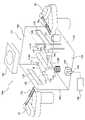
第1洗浄ユニット73A,73Bおよび第2洗浄ユニット74A,74Bは、湿式処理装置である。図3は、湿式処理装置としての第2洗浄ユニット74Aの一実施形態を示す模式図である。図3に示す第2洗浄ユニット74Aは、ウェーハなどの基板Wを洗浄するための基板洗浄装置の一実施形態である。第2洗浄ユニット74Aは、処理槽101と、処理槽101内に配置された基板保持部110と、基板保持部110に保持された基板Wの表面を洗浄する洗浄具としてのロールスポンジ112A,112Bとを備えている。基板保持部110は、基板Wの周縁部を保持する保持ローラー111を備えている。各保持ローラー111は、自身の軸心を中心に回転可能に構成されている。保持ローラー111が基板Wの周縁部を保持しながら、各保持ローラー111がその軸心を中心に回転することで、基板Wが回転する。 The
ロールスポンジ112A,112Bは、基板Wの上側と下側に配置されている。ロールスポンジ112A,112Bの軸心は水平に延びており、自身の軸心を中心に回転可能に構成されている。さらに、ロールスポンジ112A,112Bは基板Wの上面および下面に近づく方向および離れる方向に移動可能に構成されている。 The
ロールスポンジ112A,112Bに近接して2つの液体供給ノズル115A,115Bが配置されている。液体供給ノズル115A,115Bは処理槽101内に配置されている。液体供給ノズル115Aは、基板保持部110に保持された基板Wの上面を向いており、液体供給ノズル115Bは基板保持部110に保持された基板Wの下面を向いている。液体供給ノズル115A,115Bは、基板Wの上面および下面に液体を供給するように構成されている。液体は、薬液または純水などの処理液、および/または純水などのリンス液である。薬液およびリンス液を別々に供給するための4つ以上の液体供給ノズルを設けてもよい。基板Wの処理に使用される液体の種類は、本実施形態に限定されず、基板処理の目的に基づいて適宜選択される。 Two
基板Wは次のようにして洗浄される。保持ローラー111は、基板Wの周縁部を保持しながら自身の軸心を中心に回転することで、基板Wを回転させる。液体供給ノズル115A,115Bは薬液または純水などの処理液を回転する基板Wの上面および下面に供給しながら、回転するロールスポンジ112A,112Bが基板Wの上面および下面に接触する。ロールスポンジ112A,112Bは、処理液の存在下で基板Wの上面および下面をスクラブする。所定の時間が経過すると、ロールスポンジ112A,112Bは基板Wから離れる。次いで、液体供給ノズル115A,115Bは、純水などのリンス液を回転する基板Wの上面および下面に供給し、基板Wの上面および下面をリンスする。このようにして基板Wの処理(洗浄)が行われる。 The substrate W is washed as follows. The holding
処理槽101の底部102にはドレインポート118が配置されている。基板Wの洗浄(処理)に使用された処理液およびリンス液などの液体は、処理槽101からドレインポート118を通って排出される。処理槽101の底部102はドレインポート118に向かって僅かに傾いており、液体がドレインポート118に向かって流れるようになっている。ドレインポート118は処理槽101の底部102から上方に突出している。ドレインポート118の全体には多数の穴が形成されており、ドレインポート118自体はストレーナとしても機能する。すなわち、液体は、ドレインポート118の穴を通ってドレインポート118内に流入する。本実施形態では、ドレインポート118は円筒形状を有しているが、他の形状を有してもよい。一実施形態では、ドレインポート118は、処理槽101の側壁103または側壁104または背面壁106の下端に設けられてもよい。 A
処理槽101の底部102には排気ポート121がさらに配置されている。排気ポート121は、図示しない真空ポンプに接続されている。排気ポート121は、処理槽101の内部空間から空気を常に排気しており、これにより処理槽101内には負圧が形成されている。処理槽101の底部102上の液体が排気ポート121内に進入しないように、排気ポート121は処理槽101の底部102から上方に突出している。本実施形態では、排気ポート121は処理槽101の底部102に設けられているが、一実施形態では、処理槽101の側壁103または側壁104または背面壁106に設けられてもよい。 An
処理槽101の両側には、基板Wを処理槽101内に搬入するための第1搬送ロボット77と、基板Wを処理槽101から搬出するための第2搬送ロボット78が配置されている。処理槽101の2つの側壁103,104には基板入口128および基板出口129がそれぞれ形成されている。これらの基板入口128および基板出口129は、それぞれ入口シャッター132および出口シャッター133で覆われている。これらシャッター132,133は図示しないアクチュエータで開閉されるようになっている。 On both sides of the
基板入口128および基板出口129は、空気取り入れ口としても機能する。入口シャッター132および出口シャッター133が閉じているとき、処理槽101は完全に密閉されてはいない。すなわち、入口シャッター132および出口シャッター133が閉じているときでも、空気は、入口シャッター132と基板入口128との間の僅かな隙間、および出口シャッター133と基板出口129との間の僅かな隙間から処理槽101内に流入し、処理槽101内に空気の流れを形成する。入口シャッター132および出口シャッター133のうちのいずれかが開いたとき、大量の空気が基板入口128または基板出口129を通って処理槽101内に流入し、排気ポート121を通じて処理槽101から排出される。このとき、処理槽101内には空気の強い流れが形成される。 The
処理槽101の上方には、クリーンエア供給装置140が配置されている。このクリーンエア供給装置140は、HEPAフィルタまたはULPAフィルタと、ファンとを備えたファンフィルタユニットである。クリーンエア供給装置140は、周囲の空気から塵や粒子を取り除き、清浄化された空気の流れを形成する。クリーンエア供給装置140は、処理槽101の基板入口128および基板出口129よりも高い位置に配置される。クリーンエア供給装置140によって清浄化された空気は、上述の基板入口128および基板出口129、あるいは入口シャッター132と基板入口128との間の僅かな隙間、および出口シャッター133と基板出口129との間の僅かな隙間を介して処理槽101内に流入し、さらに排気ポート121に向かって流れる。処理槽101は、清浄空気の環境下に置かれ、これにより処理槽101内で処理される基板Wの汚染が防止される。尚、クリーンエア供給装置140の設置場所は、処理槽101の上方としたがこれに代えて、第1搬送ロボット77および第2搬送ロボット78のそれぞれが上下方向に移動する空間の最上部(例えば洗浄部4の天井部)で計2箇所に設置してもよい。 A clean
上述したように、ドレインポート118はストレーナとしても機能する。このため、基板の破片や異物によりドレインポート118が詰まることがある。ドレインポート118が詰まると、薬液や純水などの基板Wの処理に使用された液体を処理槽101から排出することができない。結果として、処理槽101内の液面が上昇し、処理槽101内の清浄度が低下してしまう。 As mentioned above, the
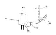
そこで、処理槽101内の液面を検出するための光学式液面検出センサ145が処理槽101の底部102に設けられている。光学式液面検出センサ145は処理槽101の内部を向いて配置されている。さらに、処理槽101の底部102には、光学式液面検出センサ145に対面するセンサターゲットカバー150が設けられている。光学式液面検出センサ145は、信号処理部148に電気的に接続されており、光学式液面検出センサ145から出力された信号は信号処理部148に送られるようになっている。 Therefore, an optical liquid
図4は、光学式液面検出センサ145およびセンサターゲットカバー150を示す斜視図である。光学式液面検出センサ145およびセンサターゲットカバー150の両方は、支持部材152に固定されている。この支持部材152は、処理槽101の底部102に固定されており、処理槽101の底部102から上方に突出している。光学式液面検出センサ145は、支持部材152の外面に固定されており、センサターゲットカバー150は支持部材152の頂面に固定されている。センサターゲットカバー150の下端と処理槽101の底部102との間には隙間Gが形成されている。処理槽101内の液面が上昇すると、液体は隙間Gからセンサターゲットカバー150内に進入するようになっている。 FIG. 4 is a perspective view showing the optical liquid
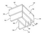
センサターゲットカバー150は、内壁構造体154と、内壁構造体154を囲む外壁構造体164とを備える。内壁構造体154は2つの内側壁155を有し、外壁構造体164は、2つの内側壁155の外側にそれぞれ配置された2つの外側壁165と、2つの外側壁165に接続された天井壁167を有している。内壁構造体154は天井壁を有しない。外壁構造体164の下端は、内壁構造体154の下端よりも高い位置にあり、外壁構造体164の上端は、内壁構造体154の上端よりも高い位置にある。外壁構造体164の幅は、内壁構造体154の幅よりも大きい。 The
図5は、処理槽101の正面壁105が底部102に固定されている状態を示す斜視図である。上述した図4は、処理槽101の正面壁105が取り外された状態を示している。図5に示すように、正面壁105には光学式液面検出センサ145の外形に沿った形状の切り欠き105aが形成されている。光学式液面検出センサ145がこの切り欠き105a内に位置した状態で、正面壁105は底部102に固定される。正面壁105は、支持部材152の外面および底部102に隙間なく接触しており、処理槽101内の液体が切り欠き105aを通って外部に漏れないようになっている。 FIG. 5 is a perspective view showing a state in which the
図6は、図4に示すセンサターゲットカバー150の斜視図であり、図7はセンサターゲットカバー150の下方から見た斜視図であり、図8は、センサターゲットカバー150の一部を破線で示した斜視図である。センサターゲットカバー150は、センサターゲットとしての反射板180を備えている。反射板180は、内壁構造体154に囲まれている。内壁構造体154は、反射板180に対向する内保護壁158と、反射板180および内保護壁158の両側に配置された2つの内側壁155とを備えている。内保護壁158は2つの内側壁155の間に配置されており、内保護壁158の両端は2つの内側壁155にそれぞれ接続されている。 6 is a perspective view of the
内壁構造体154は外壁構造体164に囲まれている。外壁構造体164は、2つの内側壁155の外側にそれぞれ配置された2つの外側壁165と、内保護壁158の外側に配置された外保護壁168と、天井壁167とを備えている。外保護壁168は2つの外側壁165の間に配置されており、外保護壁168の両端は2つの外側壁165にそれぞれ接続されている。2つの外側壁165と、外保護壁168は、天井壁167に固定されている。2つの外側壁165および外保護壁168は、天井壁167から下方に延びている。内保護壁158は、反射板180と外保護壁168との間に配置されている。内保護壁158と外保護壁168は、反射板180に液体が付着することを防止する二重の保護壁を構成している。 The
内壁構造体154と外壁構造体164との間にスペーサ171,172が配置されている。より具体的には、2つの内側壁155の上部の一方側には2つの第1スペーサ171がそれぞれ固定されている。さらに、2つの内側壁155の上部の他方側には2つの第2スペーサ172がそれぞれ固定されている。第1スペーサ171および第2スペーサ172は、2つの内側壁155から外側に突出するとともに、2つの内側壁155の上端から上方に突出している。各外側壁165は第1スペーサ171および第2スペーサ172に接続されており、外保護壁168は2つの第2スペーサ172に接続されている。天井壁167の下面は、2つの第1スペーサ171および2つの第2スペーサ172に接続されている。天井壁167の下面および外側壁165の上端は、内側壁155の上端および内保護壁158の上端よりも高い位置にある。
内壁構造体154と外壁構造体164は、2つの第1スペーサ171および2つの第2スペーサ172によって連結され、2つの第1スペーサ171および2つの第2スペーサ172によって内壁構造体154と外壁構造体164との間に隙間が形成されている。より具体的には、内側壁155の外面と外側壁165の内面との間には隙間H1が形成され、内保護壁158の外面と外保護壁168の内面との間には隙間H2が形成され、内側壁155および内保護壁158のそれぞれの上端と天井壁167の下面との間には隙間H3が形成されている。内壁構造体154の内部空間は、これら隙間H1,H2,H3を通じて外部空間に連通している。 The
本実施形態では、反射板180、内壁構造体154、外壁構造体164、第1スペーサ171、および第2スペーサ172は、アクリル樹脂などの透明な樹脂から構成されている。 In the present embodiment, the
図9は、支持部材152に固定された光学式液面検出センサ145およびセンサターゲットカバー150を示す断面斜視図である。図9に示すように、天井壁167は、支持部材152に固定されている。本実施形態では、センサターゲットカバー150の天井壁167のみが支持部材152に接触し、センサターゲットカバー150の全体が支持部材152に支持されている。上述したように、センサターゲットカバー150の下端(すなわち、2つの内側壁155および内保護壁158の下端)は、処理槽101の底部102から隙間Gを介して離間している。 FIG. 9 is a cross-sectional perspective view showing the optical liquid
光学式液面検出センサ145は、光を発する光源(例えばLED:発光ダイオード)と、光検出器とを有する。支持部材152は、通孔152aを有しており、光学式液面検出センサ145は通孔152aを覆うように支持部材152に固定されている。反射板180の一方の面は、光学式液面検出センサ145に対向しており、反射板180の他方の面は内保護壁158に対向している。内壁構造体154の内部空間は、反射板180によって第1の部屋176と第2の部屋177に仕切られている。第1の部屋176は、2つの内側壁155と反射板180とに囲まれ、第2の部屋177は、反射板180と2つの内側壁155と内保護壁158とに囲まれている。支持部材152の通孔152aは第1の部屋176内に位置している。 The optical liquid
反射板180は、光学式液面検出センサ145と内保護壁158との間に配置されている。光学式液面検出センサ145は、光を通孔152aを通じて反射板180に導き、反射板180から反射した光量を測定するように構成されている。光学式液面検出センサ145は、光量の測定値を信号処理部148に送る。信号処理部148は、光量の測定値に基づいて処理槽101内の液面の上昇を検出するように構成されている。 The
処理槽101内の液体がドレインポート118を通じて正常に排出されているとき、すなわち処理槽101内の液面が上昇していないとき、光学式液面検出センサ145は反射板180からの反射光を受け取ることができる。処理槽101内の液面が上昇すると、液体は隙間Gを通ってセンサターゲットカバー150内に進入し、反射板180が液中に浸漬される。空気と液体とでは屈折率が異なるため、光学式液面検出センサ145は反射板180からの反射光を受け取ることができない。結果として、光学式液面検出センサ145によって測定される光量が低下する。信号処理部148は、光量の測定値を光学式液面検出センサ145から受け取り、光量の測定値を予め設定されたしきい値と比較し、光量の測定値がしきい値よりも低いときに、処理槽101内の液面上昇を決定する。 When the liquid in the
反射板180に液体が付着したり、反射板180が結露すると、処理槽101内の液面が上昇していないにもかかわらず、光学式液面検出センサ145によって測定される光量が低下する。結果として、信号処理部148は、液面上昇を誤検出してしまう。特に、本実施形態のように、回転する基板Wに液体を供給しながら基板Wを処理するとき、液体が基板Wから飛散して、反射板180に付着しやすい。 When liquid adheres to the
本実施形態によれば、反射板180は内壁構造体154によって囲まれ、内壁構造体154は外壁構造体164によって囲まれている。したがって、内壁構造体154および外壁構造体164は、液体の反射板180への付着を防止することができる。さらに、内壁構造体154と外壁構造体164との間には隙間が形成されているので、センサターゲットカバー150内に空気の流れが形成される。この空気の流れは、センサターゲットカバー150内の反射板180での結露を防止することができる。通常、処理槽101の内部は、モータなどの発熱源および基板Wの処理に使用される液体の存在に起因して、高温多湿の状態となる。このような高温多湿の環境下でも、上述したセンサターゲットカバー150は、通気性がよいので、その内部に配置された反射板180での結露を防止することができる。したがって、光学式液面検出センサ145は、処理槽101内の液面を正確に検出することができる。 According to the present embodiment, the
図10は、処理槽101内の液面が上昇したときの動作を示すフロチャートである。処理槽101内の液面が何らかの原因で上昇すると(ステップ1)、液体はセンサターゲットカバー150内に進入する。反射板(センサターゲット)180が液中に浸漬されると(ステップ2)、光学式液面検出センサ145によって測定される光量が低下する(ステップ3)。信号処理部148は、光量の測定値が予め設定されたしきい値よりも低いときに、図1に示す動作制御部5に液面上昇信号を送信する(ステップ4)。動作制御部5は、液面上昇信号を受け取ると、液体供給ノズル115A,115Bに接続されたバルブ(図示せず)を閉じる(ステップ5)。これにより、処理槽101内の液面の上昇が停止される(ステップ6)。 FIG. 10 is a flow chart showing the operation when the liquid level in the
次に、図3に示す湿式処理装置の一例である第2洗浄ユニット74Aの動作の一実施形態を説明する。排気ポート121から処理槽101内の空気を排気している状態で、入口シャッター132が開く。出口シャッター133は閉じたままである。入口シャッター132が開くと、クリーンエア供給装置(ファンフィルタユニット)140から供給された清浄な空気が大量に基板入口128から処理槽101内に流入し、処理槽101内に空気の強い流れが形成される。このとき、センサターゲットカバー150内にも空気の流れが形成される。さらに、処理槽101内に流入した清浄な空気によって、処理槽101内の温度が低下する。 Next, an embodiment of the operation of the
第1搬送ロボット77は、そのハンド77aに載置された処理すべき基板Wを基板入口128から処理槽101内に搬入する。基板保持部110の保持ローラー111が基板Wを受け取ると、第1搬送ロボット77のハンド77aは処理槽101の外に移動する。次いで入口シャッター132が閉じる。保持ローラー111は、基板Wの周縁部を保持しながら自身の軸心を中心に回転することで、基板Wを回転させる。液体供給ノズル115A,115Bは薬液または純水などの処理液を回転する基板Wの上面および下面に供給しながら、回転するロールスポンジ112A,112Bが基板Wの上面および下面に接触する。ロールスポンジ112A,112Bは、処理液の存在下で基板Wの上面および下面をスクラブする。所定の時間が経過すると、ロールスポンジ112A,112Bは基板Wから離れる。次いで、液体供給ノズル115A,115Bは、純水などのリンス液を回転する基板Wの上面および下面に供給し、基板Wの上面および下面をリンスする。このようにして基板Wの処理(洗浄)が行われる。 The
基板Wの処理が終了した後、出口シャッター133が開く。クリーンエア供給装置(ファンフィルタユニット)140から供給された清浄な空気は大量に基板出口129から処理槽101内に流入し、処理槽101内に空気の強い流れが形成される。このとき、センサターゲットカバー150内にも空気の流れが形成される。さらに、処理槽101内に流入した清浄な空気によって、処理槽101内の温度が低下する。第2搬送ロボット78はそのハンド78aで基板Wを保持ローラー111から取り出し、処理槽101から搬出する。そして、出口シャッター133が閉じる。 After the processing of the substrate W is completed, the
基板Wの処理前、基板Wの処理中、および基板Wの処理後、処理槽101内の空気は排気ポート121から排気され続ける。入口シャッター132および出口シャッター133が閉じているときでも、空気は、入口シャッター132と基板入口128との間の僅かな隙間、および出口シャッター133と基板出口129との間の僅かな隙間から処理槽101内に流入し、処理槽101内に空気の流れを形成する。したがって、処理槽101内の空気が排気ポート121から排気され続けている限り、処理槽101内には空気の流れが形成される。この空気の流れは、センサターゲットカバー150内にも空気の流れを形成する。 Before the processing of the substrate W, during the processing of the substrate W, and after the processing of the substrate W, the air in the
図11は、センサターゲットカバー150内に形成される空気の流れを示す図である。図11に示すように、空気は、センサターゲットカバー150の内壁構造体154と外壁構造体164との間の隙間を通ってセンサターゲットの第1の部屋176および第2の部屋177(図9参照)の両方を通過する。このような空気の流れは、反射板180での結露を防止することができる。 FIG. 11 is a diagram showing a flow of air formed in the
本発明者は、反射板180の結露が除去される様子を観察するための実験を行った。実験では、上述した実施形態に係るセンサターゲットカバー150と、隙間のない密閉されたセンサターゲットカバーが用いられた。実験は、周囲の温度が23.5℃の下で、排気ポート121から処理槽101内の空気を排気しながら行われた。2つのセンサターゲットカバーの反射板を意図的に結露させた状態で実験を開始した。隙間のないセンサターゲットカバーの反射板は、実験開始から2時間経過しても結露が解消されなかったが、本実施形態に係るセンサターゲットカバー150の反射板180の結露は、実験開始から30分後にほぼ解消された。この実験結果から、内壁構造体154と外壁構造体164との間の隙間は、反射板180の結露の除去に大きく寄与することが分かった。 The present inventor conducted an experiment for observing how the dew condensation on the
上述した本実施形態に係るセンサターゲットカバー150および光学式液面検出センサ145を備えた湿式処理装置の例としては、図3に示すロールスポンジ112A,112Bを備えた基板洗浄装置に加えて、ペンスポンジを備えた基板洗浄装置、および回転する基板にスラリーを供給しながら基板を仕上げ研磨するバフ研磨装置、あるいは基板の周縁部を研磨または研削する周縁部加工装置など、基板より小型の洗浄具や加工工具により回転する基板を処理する装置が挙げられる。 As an example of the wet processing apparatus provided with the
一実施形態では、外壁構造体164の2つの外側壁165を省略し、図6,図8に示す隙間H1,H3をなくしてもよい。この場合は、図7に示す隙間H2から空気がセンサターゲットカバー150内に流入する。さらに、一実施形態では、外壁構造体164の外保護壁168を省略し、図7に示す隙間H2をなくしてもよい。この場合は、図6,図8に示す隙間H1,H3から空気がセンサターゲットカバー150内に流入する。 In one embodiment, the two
上述した実施形態は、本発明が属する技術分野における通常の知識を有する者が本発明を実施できることを目的として記載されたものである。上記実施形態の種々の変形例は、当業者であれば当然になしうることであり、本発明の技術的思想は他の実施形態にも適用しうる。したがって、本発明は、記載された実施形態に限定されることはなく、特許請求の範囲によって定義される技術的思想に従った最も広い範囲に解釈されるものである。 The above-described embodiments have been described for the purpose of allowing a person having ordinary knowledge in the technical field to which the present invention belongs to carry out the present invention. Various modifications of the above embodiment can be naturally made by those skilled in the art, and the technical idea of the present invention can be applied to other embodiments. Accordingly, the invention is not limited to the described embodiments, but is to be construed in the broadest range according to the technical ideas defined by the claims.
1 ハウジング
2 ロード/アンロード部
3 研磨部
3A,3B,3C,3D 研磨ユニット
4 洗浄部
5 動作制御部
6 第1リニアトランスポータ
7 第2リニアトランスポータ
10 研磨パッド
11 リフタ
12 スイングトランスポータ
20 フロントロード部
21 レール機構
22 搬送ロボット(ローダー)
30A,30B,30C,30D 研磨テーブル
31A,31B,31C,31D 研磨ヘッド
32A,32B,32C,32D 液体供給ノズル
33A,33B,33C,33D ドレッサ
34A,34B,34C,34D アトマイザ
72 仮置きステージ
73A,73B 第1洗浄ユニット
74A,74B 第2洗浄ユニット
75A,75B 乾燥ユニット
77 第1搬送ロボット
78 第2搬送ロボット
80 第1昇降軸
81 第2昇降軸
101 処理槽
102 底部
103,104 側壁
105 正面壁
105a 切り欠き
110 基板保持部
111 保持ローラー
112A,112B ロールスポンジ(洗浄具)
115A,115B 液体供給ノズル
118 ドレインポート
121 排気ポート
125 第1搬送ロボット
126 第2搬送ロボット
128 基板入口
129 基板出口
132 入口シャッター
133 出口シャッター
140 クリーンエア供給装置
145 光学式液面検出センサ
148 信号処理部
150 センサターゲットカバー
152 支持部材
154 内壁構造体
155 内側壁
158 内保護壁
164 外壁構造体
165 外側壁
167 天井壁
168 外保護壁
171 第1スペーサ
172 第2スペーサ
180 反射板1
30A, 30B, 30C, 30D Polishing table 31A, 31B, 31C,
115A, 115B
Claims (11)
Translated fromJapanese反射板と、
前記反射板を囲む内壁構造体と、
前記内壁構造体を囲む外壁構造体とを備え、
前記内壁構造体と前記外壁構造体との間には隙間が形成されており、
前記外壁構造体の下端は、前記内壁構造体の下端よりも高い位置にあり、前記外壁構造体の上端は、前記内壁構造体の上端よりも高い位置にある、センサターゲットカバー。A sensor target cover used in combination with an optical liquid level detection sensor.
Reflector and
The inner wall structure surrounding the reflector and
With an outer wall structure surrounding the inner wall structure,
A gap is formed between the inner wall structure and the outer wall structure.
A sensor target coverin which the lower end of the outer wall structure is higher than the lower end of the inner wall structure and the upper end of the outer wall structure is higher than the upper end of the inner wall structure .
反射板と、
前記反射板を囲む内壁構造体と、
前記内壁構造体を囲む外壁構造体とを備え、
前記内壁構造体と前記外壁構造体との間には隙間が形成されており、
前記内壁構造体は、前記反射板に対向する内保護壁と、前記反射板および前記内保護壁の両側に配置された2つの内側壁とを備える、センサターゲットカバー。A sensor target cover used in combination with an optical liquid level detection sensor.
Reflector and
The inner wall structure surrounding the reflector and
With an outer wall structure surrounding the inner wall structure,
A gap is formed between the inner wall structure and the outer wall structure.
The inner wall structure isa sensor target cover including an inner protective wall facing the reflector and two inner side walls arranged on both sides of the reflector and the inner protective wall.
前記光学式液面検出センサに対向して配置され、前記光学式液面検出センサから導かれた光を、前記光学式液面検出センサに向けて反射させる反射板と、
2つの外側壁および天井壁を有する外壁構造体と、
前記外壁構造体内に収容された内壁構造体とを備え、
前記内壁構造体と前記外壁構造体との間に隙間が設けられており、前記内壁構造体の内部空間は前記隙間を通じて外部空間に連通している、装置。An optical liquid level detection sensor with a light source and a photodetector that emits light,
A reflector arranged facing the optical liquid level detection sensor and reflecting the light guided from the optical liquid level detection sensor toward the optical liquid level detection sensor.
An outer wall structure with two outer walls and a ceiling wall,
With an inner wall structure housed in the outer wall structure,
An apparatus in which a gap is provided between the inner wall structure and the outer wall structure, and the internal space of the inner wall structure communicates with the outer space through the gap.
前記処理槽内に配置された基板保持部と、
前記処理槽に配置されたドレインポートと、
前記処理槽内に配置された液体供給ノズルと、
前記処理槽内の液面を検出する光学式液面検出センサと、
前記光学式液面検出センサに対面するセンサターゲットカバーを備え、
前記センサターゲットカバーは請求項1乃至5のいずれか一項に記載のセンサターゲットカバーである、湿式処理装置。With the processing tank
The substrate holding portion arranged in the processing tank and
The drain port arranged in the processing tank and
The liquid supply nozzle arranged in the processing tank and
An optical liquid level detection sensor that detects the liquid level in the processing tank, and
A sensor target cover facing the optical liquid level detection sensor is provided.
The wet processing apparatus, wherein the sensor target cover is the sensor target cover according to any one of claims 1 to5 .
研磨された基板を洗浄する複数の湿式処理装置を備えた洗浄部と、
研磨された基板を前記研磨部から前記洗浄部へと搬送する搬送装置を備え、
前記湿式処理装置は、請求項7乃至10のいずれか一項に記載の湿式処理装置である、基板処理装置。The polishing part that polishes the substrate and
A cleaning unit equipped with multiple wet processing devices for cleaning the polished substrate,
A transport device for transporting the polished substrate from the polished portion to the cleaning portion is provided.
The wet processing apparatus is a substrate processing apparatus according to any one of claims7 to10 .
Priority Applications (3)
| Application Number | Priority Date | Filing Date | Title |
|---|---|---|---|
| JP2018148638AJP7080766B2 (en) | 2018-08-07 | 2018-08-07 | Sensor target cover used in combination with liquid level detection sensor, and wet processing equipment |
| SG10201907189RASG10201907189RA (en) | 2018-08-07 | 2019-08-05 | Sensor target cover used in combination with liquid level detection sensor, wet processing device, substrate processing device, and sensor assembly |
| US16/532,493US11846536B2 (en) | 2018-08-07 | 2019-08-06 | Sensor target cover used in combination with liquid level detection sensor, wet processing device, substrate processing device, and sensor assembly |
Applications Claiming Priority (1)
| Application Number | Priority Date | Filing Date | Title |
|---|---|---|---|
| JP2018148638AJP7080766B2 (en) | 2018-08-07 | 2018-08-07 | Sensor target cover used in combination with liquid level detection sensor, and wet processing equipment |
Publications (3)
| Publication Number | Publication Date |
|---|---|
| JP2020024137A JP2020024137A (en) | 2020-02-13 |
| JP2020024137A5 JP2020024137A5 (en) | 2021-05-20 |
| JP7080766B2true JP7080766B2 (en) | 2022-06-06 |
Family
ID=69405703
Family Applications (1)
| Application Number | Title | Priority Date | Filing Date |
|---|---|---|---|
| JP2018148638AActiveJP7080766B2 (en) | 2018-08-07 | 2018-08-07 | Sensor target cover used in combination with liquid level detection sensor, and wet processing equipment |
Country Status (3)
| Country | Link |
|---|---|
| US (1) | US11846536B2 (en) |
| JP (1) | JP7080766B2 (en) |
| SG (1) | SG10201907189RA (en) |
Families Citing this family (3)
| Publication number | Priority date | Publication date | Assignee | Title |
|---|---|---|---|---|
| CN112303883A (en)* | 2020-09-23 | 2021-02-02 | 温州水琳黛贸易有限公司 | Energy-saving and environment-friendly air conditioner utilizing accumulated condensed water |
| US12198944B2 (en)* | 2020-11-11 | 2025-01-14 | Applied Materials, Inc. | Substrate handling in a modular polishing system with single substrate cleaning chambers |
| JP6892176B1 (en)* | 2020-11-19 | 2021-06-23 | 不二越機械工業株式会社 | Work cleaning device |
Citations (1)
| Publication number | Priority date | Publication date | Assignee | Title |
|---|---|---|---|---|
| US20080011970A1 (en) | 2006-07-13 | 2008-01-17 | Dataonline, L.L.C. | Non-contact sensor for detecting material level in a container |
Family Cites Families (14)
| Publication number | Priority date | Publication date | Assignee | Title |
|---|---|---|---|---|
| JPH0669177B2 (en) | 1983-02-23 | 1994-08-31 | 住友電気工業株式会社 | Transmission control method |
| JPH0329707Y2 (en)* | 1984-08-22 | 1991-06-25 | ||
| US4946242A (en)* | 1987-08-28 | 1990-08-07 | Hitachi, Ltd. | Optical part including integral combination of optical fiber and light emitting or receiving element and method of manufacturing the same |
| JPH1092781A (en)* | 1996-06-04 | 1998-04-10 | Ebara Corp | Substrate transfer method and apparatus |
| US5804831A (en)* | 1997-05-15 | 1998-09-08 | Casco Products Corporation | Liquid level sensor for use in a hot, pressurized liquid |
| KR100354456B1 (en) | 1999-10-27 | 2002-09-30 | 주식회사 기가트론 | An wet-rinsing and drying apparatus and the method thereof |
| WO2004008086A1 (en)* | 2002-07-16 | 2004-01-22 | Strube, Inc. | Liquid level sensor using fluorescence in an optical waveguide |
| JP3673254B2 (en)* | 2002-11-14 | 2005-07-20 | 株式会社プレテック | Liquid level detection sensor and liquid level detection method |
| IT1398785B1 (en)* | 2009-08-04 | 2013-03-18 | Illinois Tool Works | OPTICAL SENSOR TO DETECT THE LIQUID LEVEL IN A CONTAINER, IN PARTICULAR FOR A REMOVABLE CONTAINER FOR A ASSOCIATED APPLIANCE AND LENS AND METHOD |
| JP6295107B2 (en)* | 2014-03-07 | 2018-03-14 | 株式会社荏原製作所 | Substrate processing system and substrate processing method |
| JP2015230940A (en) | 2014-06-04 | 2015-12-21 | 株式会社荏原製作所 | Substrate processing module |
| TWI653701B (en)* | 2014-06-09 | 2019-03-11 | 日商荏原製作所股份有限公司 | Substrate attaching and detaching portion for substrate holder, wet substrate processing device including the substrate attaching and detaching portion, substrate processing device, and substrate transfer method |
| US10246348B2 (en)* | 2015-06-08 | 2019-04-02 | Rayvio Corporation | Ultraviolet disinfection system |
| KR102522960B1 (en) | 2015-12-14 | 2023-04-20 | 세메스 주식회사 | Apparatus for treating substrate |
- 2018
- 2018-08-07JPJP2018148638Apatent/JP7080766B2/enactiveActive
- 2019
- 2019-08-05SGSG10201907189RApatent/SG10201907189RA/enunknown
- 2019-08-06USUS16/532,493patent/US11846536B2/enactiveActive
Patent Citations (1)
| Publication number | Priority date | Publication date | Assignee | Title |
|---|---|---|---|---|
| US20080011970A1 (en) | 2006-07-13 | 2008-01-17 | Dataonline, L.L.C. | Non-contact sensor for detecting material level in a container |
Also Published As
| Publication number | Publication date |
|---|---|
| JP2020024137A (en) | 2020-02-13 |
| SG10201907189RA (en) | 2020-03-30 |
| US20200049546A1 (en) | 2020-02-13 |
| US11846536B2 (en) | 2023-12-19 |
Similar Documents
| Publication | Publication Date | Title |
|---|---|---|
| US10618140B2 (en) | Substrate processing system and substrate processing method | |
| KR102454775B1 (en) | Substrate cleaning apparatus, substrate cleaning method and substrate processing apparatus | |
| JP7080766B2 (en) | Sensor target cover used in combination with liquid level detection sensor, and wet processing equipment | |
| JP5617012B2 (en) | Substrate processing apparatus and method for operating the same | |
| TWI654698B (en) | Polishing processing assembly, substrate processing device, and polishing pad cleaning method | |
| JP6054805B2 (en) | Substrate cleaning device | |
| JP6491908B2 (en) | Substrate cleaning apparatus, substrate cleaning method, and substrate processing apparatus | |
| TWI453093B (en) | Polishing method, polishing apparatus, and program for controlling polishing apparatus | |
| TW201811451A (en) | Substrate cleaning device, substrate processing apparatus, substrate cleaning method and substrate processing method | |
| JP2008194823A (en) | Polishing device and substrate treatment device | |
| WO2016035499A1 (en) | Polishing method and polishing device | |
| TWI774680B (en) | Cleaning apparatus and substrate processing apparatus | |
| JP6794275B2 (en) | Polishing method | |
| JP2003243350A (en) | Brush cleaning method for scrub cleaning device and processing system | |
| JP2015208840A (en) | Polishing device, jig for measuring abrasive pad profile, and method for measuring abrasive pad profile | |
| JP6785605B2 (en) | Substrate processing method, substrate processing equipment, and recording medium | |
| JP2016111265A (en) | Buff processing device and substrate processing device | |
| JP2008132592A (en) | Polishing device and polishing method | |
| JP2015015284A (en) | Substrate cleaning device and substrate cleaning method | |
| TW202410144A (en) | Substrate processing device, substrate processing method, and storage medium | |
| JP7383118B2 (en) | grinding equipment | |
| JP6412385B2 (en) | Conditioning unit, buff processing module, substrate processing apparatus, and dress rinse method | |
| JP2021130148A (en) | Grinding system, and grinding method | |
| JP6353774B2 (en) | Wafer grinding equipment | |
| CN113539888A (en) | Substrate processing apparatus |
Legal Events
| Date | Code | Title | Description |
|---|---|---|---|
| A521 | Request for written amendment filed | Free format text:JAPANESE INTERMEDIATE CODE: A523 Effective date:20210407 | |
| A621 | Written request for application examination | Free format text:JAPANESE INTERMEDIATE CODE: A621 Effective date:20210407 | |
| A977 | Report on retrieval | Free format text:JAPANESE INTERMEDIATE CODE: A971007 Effective date:20220218 | |
| A131 | Notification of reasons for refusal | Free format text:JAPANESE INTERMEDIATE CODE: A131 Effective date:20220301 | |
| A521 | Request for written amendment filed | Free format text:JAPANESE INTERMEDIATE CODE: A523 Effective date:20220407 | |
| TRDD | Decision of grant or rejection written | ||
| A01 | Written decision to grant a patent or to grant a registration (utility model) | Free format text:JAPANESE INTERMEDIATE CODE: A01 Effective date:20220426 | |
| A61 | First payment of annual fees (during grant procedure) | Free format text:JAPANESE INTERMEDIATE CODE: A61 Effective date:20220525 | |
| R150 | Certificate of patent or registration of utility model | Ref document number:7080766 Country of ref document:JP Free format text:JAPANESE INTERMEDIATE CODE: R150 | |
| R250 | Receipt of annual fees | Free format text:JAPANESE INTERMEDIATE CODE: R250 |