JP7078458B2 - Steering angle determination device and self-driving car - Google Patents
Steering angle determination device and self-driving carDownload PDFInfo
- Publication number
- JP7078458B2 JP7078458B2JP2018103663AJP2018103663AJP7078458B2JP 7078458 B2JP7078458 B2JP 7078458B2JP 2018103663 AJP2018103663 AJP 2018103663AJP 2018103663 AJP2018103663 AJP 2018103663AJP 7078458 B2JP7078458 B2JP 7078458B2
- Authority
- JP
- Japan
- Prior art keywords
- steering angle
- steering
- determining device
- unit
- scene
- Prior art date
- Legal status (The legal status is an assumption and is not a legal conclusion. Google has not performed a legal analysis and makes no representation as to the accuracy of the status listed.)
- Active
Links
Images


Landscapes
- Traffic Control Systems (AREA)
- Steering Control In Accordance With Driving Conditions (AREA)
- Control Of Driving Devices And Active Controlling Of Vehicle (AREA)
Description
Translated fromJapanese本開示は、自動操舵の技術に関する。 The present disclosure relates to an automatic steering technique.
従来、車両走行に伴い検出され複数種類の特徴量の時系列データを学習データとして、運転者の運転特徴により近い運転行動を推定する技術が知られている(特許文献1)。 Conventionally, there is known a technique of estimating driving behavior closer to a driver's driving characteristics by using time-series data of a plurality of types of features detected as the vehicle travels as learning data (Patent Document 1).
従来の技術では、運転行動を推定するために、運転者が実際に車両を走行させたときの複数種類の特徴量からなる学習データを用いている。しかしながら、運転者が運転操作を行わない自動運転の場合には、運転者が運転操作を行ったことによって生成された学習データを用いることができない。これにより、車両を自動運転する場合においては、運転者による軌跡と、自動運転による軌跡との乖離が大きくなる可能性が生じ得る。 In the conventional technique, in order to estimate the driving behavior, learning data consisting of a plurality of types of features when the driver actually drives the vehicle is used. However, in the case of automatic driving in which the driver does not perform the driving operation, the learning data generated by the driver performing the driving operation cannot be used. As a result, when the vehicle is automatically driven, there is a possibility that the deviation between the locus by the driver and the locus due to the automatic driving becomes large.
本開示は、上述の課題を解決するためになされたものであり、以下の形態として実現することが可能である。 The present disclosure has been made to solve the above-mentioned problems, and can be realized as the following forms.
本開示の一形態によれば、車両(1)の周囲を撮像する撮像部(21)と、前記車両の位置および向きを取得する位置取得部(30)とを備える前記車両に搭載される操舵角決定装置(40)が提供される。この操舵角決定装置は、前記位置取得部が取得した情報を用いて、進行方向における前記車両が走行する道路種別を含む走行シーンを決定するシーン決定部(41)と、前記撮像部の撮像画像を用いて、走行車線に沿って走行する通常操舵パターンと、障害物を回避するための回避操舵パターンとを含む操舵パターン群の中から前記車両が採るべき操舵パターンを識別する操舵識別部(42)と、前記撮像画像と、前記走行シーンと、前記操舵パターンとを用いて操舵角を決定する操舵角決定部(49)と、を備える。According to one embodiment of the present disclosure, steering mounted on the vehicle including an image pickup unit (21) that images the surroundings of the vehicle (1) and a position acquisition unit (30) that acquires the position and orientation of the vehicle. An angle determination device (40) is provided. This steering angle determining device uses the information acquired by the position acquisition unit to determine a driving sceneincluding the road type on which the vehicle travels in the traveling direction, and an image captured by the imaging unit. A steering identification unit (42) that identifies a steering pattern to be adopted by the vehiclefrom a steering pattern group including a normal steering pattern traveling along a traveling lane and an avoidance steering pattern for avoiding obstacles. ), The captured image, the traveling scene, and a steering angle determining unit (49) that determines the steering angle using the steering pattern.
上記形態の操舵角決定装置によれば、操舵角を決定するために、撮像画像に加え、走行シーンと操舵パターンとを用いることで、運転者が行う操舵と、操舵角決定部が決定する操舵角による操舵との乖離が大きくなる可能性を低減できる。 According to the steering angle determining device of the above embodiment, in order to determine the steering angle, the steering performed by the driver and the steering determined by the steering angle determining unit are used by using the driving scene and the steering pattern in addition to the captured image. It is possible to reduce the possibility that the deviation from steering due to the angle becomes large.
A.実施形態:
図1に示す自動運転車1は、少なくとも自動操舵が可能なレベル以上の自動運転車である。自動運転車1は、操舵角決定装置としてのECU40と、撮像部としてのカメラ21と、位置取得部30と、地図データ31と、操舵角センサ34と、ステアリング装置15と、ステアリングホイール17と、を備える。A. Embodiment:
The self-driving
ECU40は、自動操舵を行うために、操舵角(操舵量)としての最終操舵角を決定し、決定した最終操舵角となるようにステアリング装置15に指令を出す。ECU40の詳細は後述する。 The
カメラ21は、自動運転車1の周囲を撮像する。例えば、カメラ21は、自動運転車1の前方を撮像する。カメラ21によって予め定めた時間間隔ごとに撮像された撮像画像は、ECU40に送信される。なお、カメラ21は単眼カメラであってもよいし、ステレオカメラであってもよい。また、カメラ21は、自動運転車1の前方、側方、後方を撮像するために複数設けられていてもよい。 The
位置取得部30は、自動運転車1の位置(緯度および経度)と進行方向である向きを取得して、取得結果をECU40に送信する。位置取得部30は、例えば、GNSS(Global Navigation Satellite System)を構成する人工衛星からアンテナを介して航法信号を受信する受信機である。 The
地図データ31は、道路情報を格納したデータであり、例えば、道路情報(リンクデータやノードデータ)と、その道路の種別(一般道路や高速道路やパーキングエリア)などを格納している。操舵角センサ34は、例えば、ステアリングシャフトに取り付けられ、操舵角を検出する。 The
ステアリング装置15は、図示しないモータ等を備える。ステアリング装置15は、ECU40から入力された最終操舵角を実現するための動作をすると共に、最終操舵角に応じてステアリングホイール17を回転させる。 The
ECU40は、自動操舵機能がオンに設定されている間、繰り返し、操舵角決定処理を実行する。ステアリング装置15は、自動操舵機能がオフに設定されている間、電動パワーステアリング装置として機能する。 The
図2に示すように、ECU40は、シーン決定部41と、操舵識別部42と、操舵角決定部49と、を備える。 As shown in FIG. 2, the
シーン決定部41は、位置取得部30が取得した情報PIを用いて、自動運転車1の進行方向における走行シーンを決定する。具体的には、シーン決定部41は、情報PIに含まれる緯度情報、経度情報、および、向き情報から、地図データ31上における自動運転車1の現在位置と進行方向とを特定し、特定した現在位置および進行方向における道路種別と、自動運転車1の走行車線の曲がりの程度(例えば、曲率)とを走行シーンとして決定する。上記のごとく、シーン決定部41は、緯度情報と経度情報に加え、向き情報を用いることでより精度良く走行シーンを決定できる。 The
操舵識別部42は、カメラ21の撮像画像IMを用いて、自動運転車1が採るべき操舵パターンを識別する。操舵パターンとしては、走行車線に沿って走行する通常操舵パターンと、進行方向側(例えば、前方側)に停車する他車両などの障害物が位置するために障害物を回避するための回避操舵パターンとがある。 The
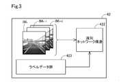
図3に示すように、操舵識別部42は、識別ネットワーク構造422と、ラベルデータ群423とを有する。識別ネットワーク構造422は、LRCN(Long Recurrent Conventional Network)を用いて構成されている。ラベルデータ群423は、過去に収集した進行方向ごとの複数の撮像画像IMと、撮像画像IMごとに操舵パターンを区分したデータである。つまりラベルデータ群423は、撮像画像IMを解析し、自動運転車1の進行方向に障害物があるか否かの状況に応じて操舵パターンを区分したデータである。例えば、自動運転車1の進行方向側に停車中の他車両が位置する撮像画像IMには、操舵パターンとして回避操舵パターンが紐付けられている。また例えば、自動運転車1の進行方向側に停車中の他車両が位置しない撮像画像IMには、操舵パターンとして通常操舵パターンが紐付けられている。 As shown in FIG. 3, the
識別ネットワーク構造422は、このラベルデータ群423のデータを教師データ(真値)として用いて、識別ネットワーク構造422に入力された3枚の撮像画像IMk,IMk+1,IMk+2のそれぞれについて、操舵パターンを識別する。The
3枚の撮像画像IMk,IMk+1,IMk+2は、同じ走行シーン(例えば、高速道路を走行するシーンや、一般道路を走行するシーン)において時系列に並んだ画像であり、時点k+2が最終決定部48によって最終操舵角を決定する対象となる時点であり、時点k+1は時点k+2よりも一つ前の時点であり、時点kは時点k+1よりも一つ前の時点である。The three captured images IMk , IMk + 1 , and IMk + 2 are images arranged in chronological order in the same driving scene (for example, a scene driving on a highway or a scene driving on a general road), and the time point k + 2 is the final. It is a time point for which the final steering angle is determined by the
以上のように、操舵識別部42は、同じ走行シーンにおいて時系列に並んだ複数の撮像画像IMk,IMk+1,IMk+2のそれぞれについて、自動運転車1の進行方向における状況と前記操舵パターンとが紐付けられた識別ネットワーク構造422を用いて操舵パターンを識別する。これにより、操舵パターンを容易に識別できる。なお、識別ネットワーク構造422は、撮像画像IMに対する実際の走行シーンを真値として与えて学習した後に、ECU40の一部として組み込まれる。As described above, the
操舵角決定部49(図2)は、撮像画像IMk,IMk+1,IMk+2と、走行シーンと、操舵パターンとを用いて操舵角を決定する。操舵角決定部49は、第1操舵角算出部44と、第2操舵角算出部46と、最終決定部48とを備える。The steering angle determining unit 49 (FIG. 2) determines the steering angle using the captured images IMk , IMk + 1 , IMk + 2 , the traveling scene, and the steering pattern. The steering
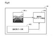
第1操舵角算出部44(図4)は、撮像画像IMk+2を用いて、時点k+2において自動運転車1が採るべき第1操舵角Zk+2を算出する。図4に示すように、第1操舵角算出部44は、操舵角ネットワーク構造442と、操舵角データ群443とを有する。操舵角ネットワーク構造442は、畳み込みニューラルネットワークであるVGG16を用いて構成されている。本実施形態において用いる操舵角ネットワーク構造442は、VGG16におけるニューロンの数やレイヤー数を適宜変更して用いてもよい。操舵角データ群443は、操舵パターンと様々な走行シーンごとに第1操舵角Zを紐付けたデータである。The first steering angle calculation unit 44 (FIG. 4) calculates the first steering angle Zk + 2 to be taken by the
第1操舵角算出部44には、撮像画像IMk+2と、シーン決定部41によって決定された時点k+2における走行シーンと、操舵識別部42によって識別された時点k+2における操舵パターンとが入力され、操舵角ネットワーク構造442は操舵角データ群443を参照することで時点k+2における第1操舵角Zk+2を算出する。The captured image IMk + 2 , the traveling scene at the time point k + 2 determined by the
第1操舵角算出部44の操舵角ネットワーク構造442は、走行シーンと操縦パターンと算出する第1操舵角Zとの関係を学習によって構築したネットワーク構造である。 The steering
第2操舵角算出部46(図2)は、第1操舵角Zk+2と、時点k+1および時点kにおいて撮像された撮像画像IMk+1,IMkにおける、最終決定部48によって決定された最終操舵角Xk+1,Xkとを用いて第2操舵角Yk+2を算出する。The second steering angle calculation unit 46 (FIG. 2) has a first steering angle Zk + 2 , and final steering angles determined by the
図5に示すように、第2操舵角算出部46は、第1ネットワーク構造310と、第2ネットワーク構造330とを備える。第2操舵角算出部46において、入力は第1操舵角Zk+2と、過去(一つ前の時点と、二つ前の時点)の最終操舵角である過去操舵角Xk+1,Xkである。入力値としての3つの値を入力値セットと呼ぶ。第1ネットワーク構造310は第1操舵角ZK+2を過去操舵角Xk+1,Xkで修正し、第2ネットワーク構造330は、第1ネットワーク構造によって修正された値を調整して第2操舵角Yk+2を算出する。As shown in FIG. 5, the second steering
入力値セットは、第1ネットワーク構造310に入力される。具体的には、入力値セットは、ゲーティングネットワーク311と、エキスパートネットワーク群320とのそれぞれに入力される。エキスパートネットワーク群320は、第1エキスパートネットワーク321と、第2エキスパートネットワーク322と、第3エキスパートネットワーク323とを備える。入力値セットは、第1~第3エキスパートネットワーク321~323のそれぞれに入力される。 The input value set is input to the
ゲーティングネットワーク311は、入力値セットが入力されると、重みgk1,重みgk2,及び重みgk3を出力する。gk1+gk2+gk3=1である。The
重みgk1は,直進するための操舵角を、第2操舵角Yk+2として出力すべき尤もらしさを意味する。重みgk2は,右に操舵するための操舵角を、第2操舵角Yk+2として出力すべき尤もらしさを意味する。重みgk3は,左に操舵するための操舵角を、第2操舵角Yk+2として出力すべき尤もらしさを意味する。The weight gk1 means the plausibility that the steering angle for going straight should be output as the second steering angle Yk + 2 . The weight gk2 means the plausibility that the steering angle for steering to the right should be output as the second steering angle Yk + 2 . The weight gk3 means the plausibility that the steering angle for steering to the left should be output as the second steering angle Yk + 2 .
本実施形態におけるゲーティングネットワーク311は、重みgk1,重みgk2,及び重みgk3の何れか1つの値を1に決定する。このため、残りの2つの値はゼロになる。つまり、本実施形態におけるゲーティングネットワーク311は、直進すべきか、右に操舵すべきか、左に操舵すべきかを、一意に決定していることになる。The
第1エキスパートネットワーク321は、入力値セットが入力されると、操舵角θk1を出力する。操舵角θk1は、直進すべきであると仮定した場合に、入力値セットから導かれる操舵角である。The
第2エキスパートネットワーク322は、入力値セットが入力されると、操舵角θk2を出力する。操舵角θk2は、右に操舵すべきであると仮定した場合に、入力値セットから導かれる操舵角である。The
第3エキスパートネットワーク323は、入力値セットが入力されると、操舵角θk3を出力する。操舵角θk3は、左に操舵すべきであると仮定した場合に、入力値セットから導かれる操舵角である。The
ゲーティングネットワーク311及びエキスパートネットワーク群320からの出力は、第2ネットワーク構造330に入力される。第2ネットワーク構造330に入力されるのは、3つの値である。具体的にはθk1×gk1、θk2×gk2、θk3×gk3が入力される。gk1、gk2、gk3のうちの2つはゼロであるので、実質的にはエキスパートネットワーク群320から出力された3つの値のうち、値が1である重みに対応する値のみが入力されることになる。The output from the
第2ネットワーク構造330は、リファインメントネットワークである。第2ネットワーク構造330は、2層の隠れ層から構成される。2層のそれぞれは、32のユニットから構成される。1層目と2層目とのユニットは、全結合されている。入力層と第1層目とのユニットも全結合されており、第2層目のユニットと出力層とも全結合されている。第2ネットワーク構造330による微調整を経て、第2操舵角Yk+2が出力される。The
第1ネットワーク構造310を構成するゲーティングネットワーク311およびエキスパートネットワーク群320は、LSTMによって構成されている。LSTMは、Long Short-Term Memoryの頭字語である。LSTMは、リカレントニューラルネットワークの一種である。LSTMは、選択的な忘却や、長期的な依存関係の学習ができるという特徴を有する。このため、入力値Xk,XK+1,ZK+2に基づき修正する処理に適している。The
以上のように、第2操舵角算出部46は、第1操舵角Zk+2と、時点K+2にける撮像画像IMK+2と走行シーンが同じであり、過去に撮像された撮像画像である過去撮像画像IMK+1,IMKを一の撮像画像として算出された最終操舵角である過去操舵角Xk+1,XKとを用いて、第2操舵角Yk+2を算出する。As described above, the second steering
最終決定部48は、第1操舵角Zk+2と第2操舵角Yk+2とを用いて、時点K+2における最終操舵角Xk+2を決定する。決定方法としては、第1操舵角Zk+2に対する尤度と、第2操舵角Yk+2から作成される提案分布(正規分布)とを用いて、粒子フィルタ処理を適用することで時点K+2における最終操舵角Xk+2を決定する方法が採用される。第1操舵角Zk+2に対する尤度は、真の操舵角(例えば、最終操舵角XK+2)との近似の程度である。The
以上のように、本実施形態の最終操舵角XK+2の決定処理は、上記のごとく粒子フィルタ処理を適用している。つまり、この決定処理は物体の検出と追跡を同時に行う逐次追跡アルゴリズムを実現している。具体的には、現状態から起こり得る多数の次状態を、多数のパーティクルに見立て、全パーティクルの尤度に基づいた重み付け平均を次状態として予測しながら追跡を実行する処理と同種の処理であるといえる。As described above, the particle filter processing is applied to the determination processing of the final steering angle XX+ 2 of the present embodiment as described above. That is, this determination process realizes a sequential tracking algorithm that simultaneously detects and tracks an object. Specifically, it is a process similar to the process of executing tracking while assuming a large number of next states that can occur from the current state as a large number of particles and predicting a weighted average based on the likelihood of all particles as the next state. It can be said that.
決定された最終操舵角Xk+2は、ステアリング装置15(図1)に出力されることで、ステアリング装置15は最終操舵角Xk+2の自動操舵を実行する。The determined final steering angle Xk + 2 is output to the steering device 15 (FIG. 1), so that the
図6を用いて、第2操舵角算出部46の教師あり学習について説明する。教師あり学習後の第2操舵角算出部46が、自動運転車1にECU40の構成要素として搭載される。自動運転車に搭載前の第2操舵角算出部46は、運転者による操舵情報を用いて教師あり学習を実施する。具体的には、撮像画像IMk+2を第1操舵角算出部44に入力することで算出された第1操舵角Zk+2と、撮像画像IMk+1,IMkが取得されたそれぞれの時点k+1,kにおける操舵角センサ34(図1)の検出操舵角Dk+1,Dkとが第2操舵角算出部46の入力要素CIとされる。検出操舵角Dk+1,Dkは真値である。入力要素である第1操舵角Zk+2には撮像画像IMk+2が紐付けられ、同様に入力要素である検出操舵角Dk+1,Dkには対応する撮像画像IMk+1,IMkが紐付けられている。また、撮像画像IMk+2が取得された時点k+2における操舵角センサ34の検出操舵角Dk+2を第2操舵角算出部46の出力要素とする。検出操舵角Dk+2は真値である。第2操舵角算出部46は、入力要素を入力したときに、出力要素である検出操舵角Dk+2の値が出力されるように教師あり学習を実施する。With reference to FIG. 6, supervised learning of the second steering
図7を用いて、自動運転車1の自動操舵による軌跡について説明する。軌跡DT1は、走行車線Ln1において自動運転車1の進行方向前方に停車している他車両などの障害物99がない場合の、自動運転車1の軌跡である。軌跡DT2は、障害物99があり、回避操舵パターンを採る場合において、最終決定部48が決定した最終操舵角Xによって自動操舵を行った軌跡である。軌跡DT3は、ECU40において操舵識別部42を省略することで、操舵パターンを最終操舵角Xの算出のための要素として用いなかった場合の軌跡である。軌跡DT4は、障害物99がある場合に、運転者が行った操舵による軌跡である。本実施形態の自動操舵による軌跡DT3は、実際に運転者が操舵による軌跡DT4に類似した軌跡である。つまり、本実施形態によれば、最終操舵角Xを決定するために、撮像画像IMに加え、走行シーンと操舵パターンとを用いることで、軌跡DT4と軌跡DT3との乖離が大きくなる可能性を低減できる。 With reference to FIG. 7, the locus of the
B.他の実施形態:
本開示は、操舵角決定装置や自動運転車の他に種々の形態で実現することも可能であり、例えば、操舵角決定装置の制御方法、制御方法を実行させるためのプログラム、等の形態で実現することができる。また本開示は、上述の実施形態や実施例、変形例に限られるものではなく、その趣旨を逸脱しない範囲において種々の構成で実現することができる。例えば、発明の概要の欄に記載した各形態中の技術的特徴に対応する実施形態、実施例、変形例中の技術的特徴は、上述の課題の一部又は全部を解決するために、あるいは、上述の効果の一部又は全部を達成するために、適宜、差し替えや、組み合わせを行うことが可能である。また、その技術的特徴が本明細書中に必須なものとして説明されていなければ、適宜、削除することが可能である。B. Other embodiments:
The present disclosure can be realized in various forms other than the steering angle determining device and the autonomous driving vehicle, for example, in the form of a control method of the steering angle determining device, a program for executing the control method, and the like. It can be realized. Further, the present disclosure is not limited to the above-described embodiments, examples, and modifications, and can be realized with various configurations within a range not deviating from the gist thereof. For example, the technical features in the embodiments, examples, and modifications corresponding to the technical features in each of the embodiments described in the column of the outline of the invention may be used to solve some or all of the above-mentioned problems. , Can be replaced or combined as appropriate to achieve some or all of the above effects. Further, if the technical feature is not described as essential in the present specification, it can be appropriately deleted.
1 車両、21 撮像部、30 位置取得部、40 操舵角決定装置、41 シーン決定部、42 操舵識別部、49 操舵角決定部1 vehicle, 21 imaging unit, 30 position acquisition unit, 40 steering angle determination device, 41 scene determination unit, 42 steering identification unit, 49 steering angle determination unit
Claims (9)
Translated fromJapanese前記位置取得部が取得した情報を用いて、進行方向における前記車両が走行する道路種別を含む走行シーンを決定するシーン決定部(41)と、
前記撮像部の撮像画像を用いて、走行車線に沿って走行する通常操舵パターンと、障害物を回避するための回避操舵パターンとを含む操舵パターン群の中から前記車両が採るべき操舵パターンを識別する操舵識別部(42)と、
前記撮像画像と、前記走行シーンと、前記操舵パターンとを用いて操舵角を決定する操舵角決定部(49)と、を備える、操舵角決定装置。A steering angle determining device (40) mounted on the vehicle, comprising an imaging unit (21) for capturing the surroundings of the vehicle (1) and a position acquisition unit (30) for acquiring the position and orientation of the vehicle. ,
Using the information acquired by the position acquisition unit, a scene determination unit (41) that determines a travel sceneincluding the road type on which the vehicle travels in the traveling direction, and a scene determination unit (41).
Using the captured image of the imaging unit, the steering pattern to be adopted by the vehicle is identifiedfrom the steering pattern group including the normal steering pattern traveling along the traveling lane and the avoidance steering pattern for avoiding obstacles. Steering identification unit (42)
A steering angle determining device including a steering angle determining unit (49) that determines a steering angle using the captured image, the traveling scene, and the steering pattern.
前記シーン決定部は、前記位置取得部が取得した情報である前記車両の緯度情報、経度情報、および、向き情報を用いて、前記走行シーンを決定する、操舵角決定装置。The steering angle determining device according to claim 1.
The scene determination unit is a steering angle determining device that determines the traveling scene by using the latitude information, the longitude information, and the orientation information of the vehicle, which are the information acquired by the position acquisition unit.
前記操舵識別部は、同じ前記走行シーンにおいて時系列に並んだ複数の前記撮像画像のそれぞれについて、前記車両の進行方向における状況と前記操舵パターンとが紐付けられたネットワーク構造(422)を用いて、前記操舵パターンを識別する、操舵角決定装置。The steering angle determining device according to claim 1 or 2.
The steering identification unit uses a network structure (422) in which the situation in the traveling direction of the vehicle and the steering pattern are associated with each of the plurality of captured images arranged in time series in the same driving scene. , A steering angle determining device that identifies the steering pattern.
前記操舵角決定部は、
一の前記撮像画像と、前記シーン決定部で決定した前記走行シーンと、前記操舵識別部が識別した前記操舵パターンとを用いて、第1操舵角を算出する第1操舵角算出部(44)と、
前記車両に実行させる前記操舵角としての最終操舵角を決定する最終決定部(48)と、
前記第1操舵角と、前記一の撮像画像と前記走行シーンが同じであり、過去に撮像された前記撮像画像である過去撮像画像を前記一の撮像画像として決定された前記最終操舵角である過去操舵角とを用いて、第2操舵角を算出する第2操舵角算出部(46)と、を備え、
前記最終決定部は、
前記第1操舵角に対する尤度と、前記第2操舵角から作成される提案分布とを用いて、前記最終操舵角を決定する、操舵角決定装置。The steering angle determining device according to any one of claims 1 to 3.
The steering angle determining unit is
A first steering angle calculation unit (44) that calculates a first steering angle using the captured image, the traveling scene determined by the scene determination unit, and the steering pattern identified by the steering identification unit. When,
A final determination unit (48) that determines the final steering angle as the steering angle to be executed by the vehicle, and
The first steering angle is the same as the one captured image and the traveling scene, and the final steering angle is determined by using the past captured image, which is the captured image captured in the past, as the one captured image. A second steering angle calculation unit (46) for calculating a second steering angle using the past steering angle is provided.
The final decision unit
A steering angle determining device that determines the final steering angle using the likelihood with respect to the first steering angle and the proposed distribution created from the second steering angle.
前記第1操舵角算出部は、前記走行シーンと前記操舵パターンと算出する前記第1操舵角との関係を学習によって構築したネットワーク構造(442)を有する、操舵角決定装置。The steering angle determining device according to claim 4.
The first steering angle calculation unit is a steering angle determining device having a network structure (442) constructed by learning the relationship between the traveling scene, the steering pattern, and the first steering angle to be calculated.
前記第2操舵角算出部は、第1ネットワーク構造(310)と、第2ネットワーク構造(330)とを備え、
前記第1ネットワーク構造は、前記過去操舵角を用いて前記第1操舵角の修正を行い、
前記第2ネットワーク構造は、前記第1ネットワーク構造によって修正された値を調整して、前記第2操舵角を算出する、操舵角決定装置。The steering angle determining device according to claim 4 or 5.
The second steering angle calculation unit includes a first network structure (310) and a second network structure (330).
The first network structure corrects the first steering angle by using the past steering angle.
The second network structure is a steering angle determining device that calculates the second steering angle by adjusting the value corrected by the first network structure.
前記第1ネットワーク構造は、ゲーティングネットワーク(311)と、エキスパートネットワーク(320)とを有し、
前記ゲーティングネットワークおよび前記エキスパートネットワークは、LSTMによって構成されることで、前記修正を実現する、操舵角決定装置。The steering angle determining device according to claim 6.
The first network structure has a gating network (311) and an expert network (320).
The gating network and the expert network are a steering angle determining device that realizes the modification by being configured by an LSTM.
前記最終決定部は、粒子フィルタ処理によって前記最終操舵角を決定する、操舵角決定装置。The steering angle determining device according to any one of claims 4 to 7.
The final determination unit is a steering angle determining device that determines the final steering angle by particle filter processing.
前記操舵角決定部によって決定された前記操舵角を用いて、操舵を実現するステアリング装置(15)と、を備える自動運転車。The steering angle determining device according to any one of claims 1 to 8.
An autonomous vehicle including a steering device (15) that realizes steering using the steering angle determined by the steering angle determining unit.
Priority Applications (1)
| Application Number | Priority Date | Filing Date | Title |
|---|---|---|---|
| JP2018103663AJP7078458B2 (en) | 2018-05-30 | 2018-05-30 | Steering angle determination device and self-driving car |
Applications Claiming Priority (1)
| Application Number | Priority Date | Filing Date | Title |
|---|---|---|---|
| JP2018103663AJP7078458B2 (en) | 2018-05-30 | 2018-05-30 | Steering angle determination device and self-driving car |
Publications (2)
| Publication Number | Publication Date |
|---|---|
| JP2019206310A JP2019206310A (en) | 2019-12-05 |
| JP7078458B2true JP7078458B2 (en) | 2022-05-31 |
Family
ID=68768277
Family Applications (1)
| Application Number | Title | Priority Date | Filing Date |
|---|---|---|---|
| JP2018103663AActiveJP7078458B2 (en) | 2018-05-30 | 2018-05-30 | Steering angle determination device and self-driving car |
Country Status (1)
| Country | Link |
|---|---|
| JP (1) | JP7078458B2 (en) |
Families Citing this family (1)
| Publication number | Priority date | Publication date | Assignee | Title |
|---|---|---|---|---|
| DE102020203836A1 (en)* | 2020-03-25 | 2021-09-30 | Robert Bosch Gesellschaft mit beschränkter Haftung | Method for determining a value of a controller variable |
Citations (7)
| Publication number | Priority date | Publication date | Assignee | Title |
|---|---|---|---|---|
| JP2005053408A (en) | 2003-08-06 | 2005-03-03 | Sumitomo Electric Ind Ltd | Steering signal output device, imaging device, and steering system |
| JP2007164636A (en) | 2005-12-15 | 2007-06-28 | Toyota Motor Corp | Road marking line detection device |
| JP2012118909A (en) | 2010-12-03 | 2012-06-21 | Nissan Motor Co Ltd | Travel support device |
| JP2017512069A (en) | 2014-02-24 | 2017-05-18 | チルドレンズ ホスピタル メディカル センター | Methods and compositions for personalized pain management |
| JP2017144759A (en) | 2016-02-15 | 2017-08-24 | 三菱電機株式会社 | Vehicle control device |
| JP2018503161A (en) | 2014-11-13 | 2018-02-01 | エヌイーシー ラボラトリーズ アメリカ インクNEC Laboratories America, Inc. | Hyperclass expansion and regularization deep learning for fine-grained image classification |
| US20180095465A1 (en) | 2017-11-22 | 2018-04-05 | GM Global Technology Operations LLC | Systems and methods for manuevering around obstacles in autonomous vehicles |
- 2018
- 2018-05-30JPJP2018103663Apatent/JP7078458B2/enactiveActive
Patent Citations (7)
| Publication number | Priority date | Publication date | Assignee | Title |
|---|---|---|---|---|
| JP2005053408A (en) | 2003-08-06 | 2005-03-03 | Sumitomo Electric Ind Ltd | Steering signal output device, imaging device, and steering system |
| JP2007164636A (en) | 2005-12-15 | 2007-06-28 | Toyota Motor Corp | Road marking line detection device |
| JP2012118909A (en) | 2010-12-03 | 2012-06-21 | Nissan Motor Co Ltd | Travel support device |
| JP2017512069A (en) | 2014-02-24 | 2017-05-18 | チルドレンズ ホスピタル メディカル センター | Methods and compositions for personalized pain management |
| JP2018503161A (en) | 2014-11-13 | 2018-02-01 | エヌイーシー ラボラトリーズ アメリカ インクNEC Laboratories America, Inc. | Hyperclass expansion and regularization deep learning for fine-grained image classification |
| JP2017144759A (en) | 2016-02-15 | 2017-08-24 | 三菱電機株式会社 | Vehicle control device |
| US20180095465A1 (en) | 2017-11-22 | 2018-04-05 | GM Global Technology Operations LLC | Systems and methods for manuevering around obstacles in autonomous vehicles |
Also Published As
| Publication number | Publication date |
|---|---|
| JP2019206310A (en) | 2019-12-05 |
Similar Documents
| Publication | Publication Date | Title |
|---|---|---|
| CN109649393B (en) | Path planning method and device for automatically driving lane change | |
| US11919512B2 (en) | Path prediction for a vehicle | |
| US11312353B2 (en) | Vehicular control system with vehicle trajectory tracking | |
| EP3495219B1 (en) | Path prediction for a vehicle | |
| EP3548845B1 (en) | Navigation based on vehicle activity | |
| CN102815299B (en) | By in fixed for track/lane sensing of lane markings identification that keeps | |
| CN110155031A (en) | Trajectory Tracking for Vehicle Lateral Control Using Neural Networks | |
| US9734719B2 (en) | Method and apparatus for guiding a vehicle in the surroundings of an object | |
| US10929995B2 (en) | Method and apparatus for predicting depth completion error-map for high-confidence dense point-cloud | |
| US20200047752A1 (en) | Vehicle lateral motion control | |
| CN111016891A (en) | Method and device for controlling vehicle driving route tracking | |
| US20160325753A1 (en) | Road profile along a predicted path | |
| CN107933560A (en) | Controller of vehicle | |
| CN112298353A (en) | System and method for calibrating the neutral position of a steering wheel | |
| CN112537294B (en) | Automatic parking control method and electronic equipment | |
| US9586593B2 (en) | Method and system of assisting a driver of a vehicle | |
| CN110446641B (en) | Vehicle control device and vehicle control method | |
| CA2987079A1 (en) | Vehicle stop position setting apparatus and method | |
| US10272946B2 (en) | Method and system of assisting a driver of a vehicle | |
| CN109017746A (en) | Controller of vehicle, control method for vehicle and storage medium | |
| CN109949364A (en) | A kind of vehicle attitude detection accuracy optimization method based on drive test monocular cam | |
| CN113302113A (en) | Method for training vehicle trajectory and electric vehicle guidance system | |
| US20210016704A1 (en) | Steerable scanning and perception system with active illumination | |
| CN110114634B (en) | External recognition system | |
| CN114206704B (en) | Override determination method for driving assistance device and driving assistance device |
Legal Events
| Date | Code | Title | Description |
|---|---|---|---|
| A621 | Written request for application examination | Free format text:JAPANESE INTERMEDIATE CODE: A621 Effective date:20210215 | |
| A977 | Report on retrieval | Free format text:JAPANESE INTERMEDIATE CODE: A971007 Effective date:20220125 | |
| A131 | Notification of reasons for refusal | Free format text:JAPANESE INTERMEDIATE CODE: A131 Effective date:20220201 | |
| A521 | Request for written amendment filed | Free format text:JAPANESE INTERMEDIATE CODE: A523 Effective date:20220331 | |
| TRDD | Decision of grant or rejection written | ||
| A01 | Written decision to grant a patent or to grant a registration (utility model) | Free format text:JAPANESE INTERMEDIATE CODE: A01 Effective date:20220426 | |
| A61 | First payment of annual fees (during grant procedure) | Free format text:JAPANESE INTERMEDIATE CODE: A61 Effective date:20220519 | |
| R150 | Certificate of patent or registration of utility model | Ref document number:7078458 Country of ref document:JP Free format text:JAPANESE INTERMEDIATE CODE: R150 | |
| R250 | Receipt of annual fees | Free format text:JAPANESE INTERMEDIATE CODE: R250 |