JP7078414B2 - Biometric electrode device - Google Patents
Biometric electrode deviceDownload PDFInfo
- Publication number
- JP7078414B2 JP7078414B2JP2018018810AJP2018018810AJP7078414B2JP 7078414 B2JP7078414 B2JP 7078414B2JP 2018018810 AJP2018018810 AJP 2018018810AJP 2018018810 AJP2018018810 AJP 2018018810AJP 7078414 B2JP7078414 B2JP 7078414B2
- Authority
- JP
- Japan
- Prior art keywords
- rubber
- conductive
- support member
- electrode portion
- cloth
- Prior art date
- Legal status (The legal status is an assumption and is not a legal conclusion. Google has not performed a legal analysis and makes no representation as to the accuracy of the status listed.)
- Active
Links
- 229920001971elastomerPolymers0.000claimsdescription187
- 239000004744fabricSubstances0.000claimsdescription132
- 238000012545processingMethods0.000claimsdescription48
- 238000010073coating (rubber)Methods0.000claimsdescription44
- 238000009958sewingMethods0.000claimsdescription30
- 239000011248coating agentSubstances0.000claimsdescription19
- 238000000576coating methodMethods0.000claimsdescription19
- 239000004020conductorSubstances0.000claimsdescription12
- 238000000034methodMethods0.000claimsdescription9
- 239000010985leatherSubstances0.000claimsdescription6
- 239000002649leather substituteSubstances0.000claimsdescription6
- 239000000853adhesiveSubstances0.000description39
- 230000001070adhesive effectEffects0.000description39
- 230000003183myoelectrical effectEffects0.000description15
- 239000000499gelSubstances0.000description14
- 239000006071creamSubstances0.000description13
- 238000004519manufacturing processMethods0.000description12
- 239000000463materialSubstances0.000description12
- 230000000149penetrating effectEffects0.000description12
- 239000002245particleSubstances0.000description11
- 238000005259measurementMethods0.000description10
- 238000009413insulationMethods0.000description5
- 229920002379silicone rubberPolymers0.000description5
- 239000004945silicone rubberSubstances0.000description5
- BQCADISMDOOEFD-UHFFFAOYSA-NSilverChemical compound[Ag]BQCADISMDOOEFD-UHFFFAOYSA-N0.000description3
- PCHJSUWPFVWCPO-UHFFFAOYSA-NgoldChemical compound[Au]PCHJSUWPFVWCPO-UHFFFAOYSA-N0.000description3
- 239000010931goldSubstances0.000description3
- 229910052737goldInorganic materials0.000description3
- WABPQHHGFIMREM-UHFFFAOYSA-Nlead(0)Chemical compound[Pb]WABPQHHGFIMREM-UHFFFAOYSA-N0.000description3
- 210000003141lower extremityAnatomy0.000description3
- 239000002923metal particleSubstances0.000description3
- 239000004745nonwoven fabricSubstances0.000description3
- 229910052709silverInorganic materials0.000description3
- 239000004332silverSubstances0.000description3
- 229910000679solderInorganic materials0.000description3
- RYGMFSIKBFXOCR-UHFFFAOYSA-NCopperChemical compound[Cu]RYGMFSIKBFXOCR-UHFFFAOYSA-N0.000description2
- 229920000742CottonPolymers0.000description2
- 230000003321amplificationEffects0.000description2
- 229910052802copperInorganic materials0.000description2
- 239000010949copperSubstances0.000description2
- 230000000694effectsEffects0.000description2
- 239000003822epoxy resinSubstances0.000description2
- 238000001746injection mouldingMethods0.000description2
- 239000002184metalSubstances0.000description2
- 229910052751metalInorganic materials0.000description2
- 239000011817metal compound particleSubstances0.000description2
- 238000012986modificationMethods0.000description2
- 230000004048modificationEffects0.000description2
- 238000000465mouldingMethods0.000description2
- 238000003199nucleic acid amplification methodMethods0.000description2
- 229920000647polyepoxidePolymers0.000description2
- 238000003825pressingMethods0.000description2
- 239000012209synthetic fiberSubstances0.000description2
- 229920002994synthetic fiberPolymers0.000description2
- OKTJSMMVPCPJKN-UHFFFAOYSA-NCarbonChemical compound[C]OKTJSMMVPCPJKN-UHFFFAOYSA-N0.000description1
- 241000282412HomoSpecies0.000description1
- 229910021607Silver chlorideInorganic materials0.000description1
- 210000001015abdomenAnatomy0.000description1
- 210000000577adipose tissueAnatomy0.000description1
- 229910052799carbonInorganic materials0.000description1
- 238000012217deletionMethods0.000description1
- 230000037430deletionEffects0.000description1
- 238000005516engineering processMethods0.000description1
- 239000000835fiberSubstances0.000description1
- 239000011810insulating materialSubstances0.000description1
- 230000007774longtermEffects0.000description1
- 230000035515penetrationEffects0.000description1
- 229920002050silicone resinPolymers0.000description1
- HKZLPVFGJNLROG-UHFFFAOYSA-Msilver monochlorideChemical compound[Cl-].[Ag+]HKZLPVFGJNLROG-UHFFFAOYSA-M0.000description1
- 229910001220stainless steelInorganic materials0.000description1
- 239000010935stainless steelSubstances0.000description1
- 239000000758substrateSubstances0.000description1
- 210000001364upper extremityAnatomy0.000description1
- 239000002759woven fabricSubstances0.000description1
Images


Landscapes
- Measurement And Recording Of Electrical Phenomena And Electrical Characteristics Of The Living Body (AREA)
Description
Translated fromJapanese本発明は、生体測定電極装置に関する。 The present invention relates to a biometric electrode device.
心電図測定では、複数の電極が生体の複数の部位に接触させられる。また、近年、筋電義手および筋電義足が開発されている。筋電義手の技術では、生体の上肢の複数の部位の表面筋電位を測定し、これらに基づいて、義手の動きを制御する。筋電義足の技術では、生体の下肢の複数の部位の表面筋電位を測定し、これらに基づいて、義足の動きを制御する。表面筋電位の測定では、複数の電極が生体の複数の部位に接触させられる。 In electrocardiographic measurement, a plurality of electrodes are brought into contact with a plurality of parts of a living body. In recent years, myoelectric prosthetic hands and myoelectric prosthetic legs have been developed. In myoelectric prosthetic hand technology, the surface myoelectric potentials of multiple parts of the upper limbs of a living body are measured, and the movement of the prosthetic hand is controlled based on these. In the myoelectric prosthetic hand technique, the surface myoelectric potentials of multiple parts of the lower limbs of the living body are measured, and the movement of the prosthetic foot is controlled based on these. In the measurement of surface myoelectric potential, a plurality of electrodes are brought into contact with a plurality of parts of a living body.
一般に、電極は金属で製造されている。また、生体への接触面積を高めるとともに、生体へ電極を固定するために、電極と生体の間に導電性ゲルまたは導電性クリームを配置することが、行われている。特許文献1~3は、このような導電性ゲルの使用を開示する。 Generally, the electrodes are made of metal. Further, in order to increase the contact area with the living body and fix the electrode to the living body, a conductive gel or a conductive cream is placed between the electrode and the living body.
しかし、金属の電極は、硬さが高く、熱伝導率が高いため、生体に不快感を与えることがある。このため、長時間、電極を生体に装着する技術には特に不適切である。また、導電性ゲルまたは導電性クリームの使用も、生体に不快感を与えることがあり、長時間、電極を生体に装着する技術には特に不適切である。また、導電性ゲルまたは導電性クリームは、経時的に性質が変化するため、長時間の使用または繰り返しの使用には不適切である。 However, metal electrodes have high hardness and high thermal conductivity, which may cause discomfort to the living body. Therefore, it is particularly unsuitable for a technique of attaching an electrode to a living body for a long time. In addition, the use of a conductive gel or a conductive cream may also cause discomfort to the living body, and is particularly unsuitable for the technique of attaching the electrode to the living body for a long time. In addition, conductive gels or conductive creams are unsuitable for long-term use or repeated use because their properties change over time.
そこで、本発明は、生体への広い接触面積を安定して確保することができ、生体に与える不快感が少なく、長時間または繰り返し使用することができる生体測定電極装置を提供する。 Therefore, the present invention provides a biometric electrode device that can stably secure a wide contact area with a living body, has less discomfort to the living body, and can be used for a long time or repeatedly.
本発明のある態様に係る生体測定電極装置は、導電体を含有するゴムで形成されたゴム電極部と、前記ゴム電極部からの電気信号を受けて当該電気信号を処理する信号処理回路と、前記ゴム電極部が一方の面側に配置され、前記信号処理回路が他方の面側に配置された支持部材と、前記ゴム電極部と前記支持部材とを貫通し、前記ゴム電極部と前記信号処理回路とを電気的に接続する導電性糸とを備える。 The biometric electrode device according to an aspect of the present invention includes a rubber electrode portion made of rubber containing a conductor, a signal processing circuit that receives an electric signal from the rubber electrode portion and processes the electric signal. The rubber electrode portion is arranged on one surface side, and the signal processing circuit penetrates the support member arranged on the other surface side, the rubber electrode portion and the support member, and the rubber electrode portion and the signal. It is provided with a conductive thread that electrically connects to the processing circuit.
本発明の態様においては、ゴム電極部を生体に向けて、生体測定電極装置を使用することができる。ゴム電極部は、ゴム弾性を有するため、生体から力を受けると生体の輪郭に順応して変形するため、ゴム電極部自体で、生体への対向面積または接触面積を安定して確保することができる。このため、導電性ゲルまたは導電性クリームを使用することが必要ではなく、生体に不快感を与えることが少ない。また、ゴム電極部は、硬さが低く、熱伝導率が低いため、生体に与える不快感が少ない。さらにゴム電極部は、導電性ゲルまたは導電性クリームに比べて、性質が安定しているため、長時間または繰り返し使用することができる。ゴム電極部と信号処理回路との電気的接続には、ゴム電極部と支持部材とを貫通する導電性糸が使用される。生体測定電極装置の製造時に、例えば縫い針を用いて、導電性糸がゴム電極部と支持部材とを貫通するように縫うことによって、容易に生体測定電極装置を製造することができる。 In the aspect of the present invention, the biometric electrode device can be used with the rubber electrode portion facing the living body. Since the rubber electrode part has rubber elasticity, it deforms according to the contour of the living body when it receives a force from the living body, so that the rubber electrode part itself can stably secure the facing area or the contact area with the living body. can. Therefore, it is not necessary to use a conductive gel or a conductive cream, and it is less likely to cause discomfort to the living body. Further, since the rubber electrode portion has low hardness and low thermal conductivity, there is little discomfort to the living body. Further, since the rubber electrode portion has more stable properties than the conductive gel or the conductive cream, it can be used for a long time or repeatedly. A conductive thread penetrating the rubber electrode portion and the support member is used for the electrical connection between the rubber electrode portion and the signal processing circuit. At the time of manufacturing the biometric electrode device, the biometric electrode device can be easily manufactured by sewing the conductive thread so as to penetrate the rubber electrode portion and the support member by using, for example, a sewing needle.
好ましくは、前記支持部材は、生体の部位に接触させられる布、皮革または合成皮革である。この場合、生体測定電極装置の製造時に、導電性糸が布、皮革または合成皮革である支持部材を容易に貫通することができる。 Preferably, the support member is a cloth, leather or synthetic leather that comes into contact with a part of the living body. In this case, the conductive thread can easily penetrate the support member which is cloth, leather or synthetic leather at the time of manufacturing the biometric electrode device.
好ましくは、前記導電性糸は、前記ゴム電極部よりも高い導電率を有する。この場合、電気信号の伝達性を向上させることができる。 Preferably, the conductive thread has a higher conductivity than the rubber electrode portion. In this case, the transmissibility of the electric signal can be improved.
好ましくは、前記ゴム電極部は、薄肉部分と厚肉部分を有しており、前記薄肉部分の前記支持部材側の面と、前記厚肉部分の前記支持部材側の面は面一であり、前記導電性糸は、前記薄肉部分と前記支持部材とを貫通する。この場合、生体測定電極装置の使用時に、厚肉部分が生体に向けられ、薄肉部分を貫通する導電性糸が生体に接触するおそれが少ない。したがって、生体とは、ゴム電極の厚肉部に相当する領域のみの接触となるので、導電性糸が生体に接触することにより生じうるノイズの発生が防止されるか、ノイズの発生の頻度が低減する。 Preferably, the rubber electrode portion has a thin-walled portion and a thick-walled portion, and the surface of the thin-walled portion on the support member side and the surface of the thick-walled portion on the support member side are flush with each other. The conductive thread penetrates the thin-walled portion and the support member. In this case, when the biometric electrode device is used, the thick portion is directed toward the living body, and the conductive thread penetrating the thin portion is less likely to come into contact with the living body. Therefore, since the living body is in contact with only the region corresponding to the thick portion of the rubber electrode, the generation of noise that may occur due to the contact of the conductive thread with the living body is prevented, or the frequency of noise generation is high. Reduce.
好ましくは、前記ゴム電極部は、互いに離間した複数の厚肉部分を有し、複数の厚肉部分の間に前記薄肉部分が配置されている。この場合、互いに離間した厚肉部分の間に、薄肉部分が配置されているので、薄肉部分を貫通する導電性糸が生体に接触するおそれが少ない。したがって、導電性糸が生体に接触することにより生じうるノイズの発生が防止されるか、ノイズの発生の頻度が低減する。さらに、薄肉部分を挟んで互いに離間した厚肉部分が生体に向けられるため、生体測定電極装置の接触圧が厚肉部分で均一化され、生体への接触状態が安定し、電気信号が安定する。 Preferably, the rubber electrode portion has a plurality of thick-walled portions separated from each other, and the thin-walled portion is arranged between the plurality of thick-walled portions. In this case, since the thin-walled portion is arranged between the thick-walled portions separated from each other, there is little possibility that the conductive thread penetrating the thin-walled portion comes into contact with the living body. Therefore, the generation of noise that may occur when the conductive thread comes into contact with the living body is prevented, or the frequency of noise generation is reduced. Furthermore, since the thick parts separated from each other across the thin part are directed toward the living body, the contact pressure of the biometric electrode device is made uniform in the thick part, the contact state with the living body is stabilized, and the electric signal is stabilized. ..
好ましくは、前記ゴム電極部の前記薄肉部分の前記支持部材とは反対側には、布が配置されており、前記導電性糸は、前記布と前記薄肉部分と前記支持部材とを貫通する。この場合、導電性糸は、ゴム電極部の薄肉部分を覆う布と薄肉部分を貫通する。ゴム電極部が低い強度の材料で形成されていたとしても、薄肉部分を覆う布で薄肉部分が補強されているので、生体測定電極装置の製造時に、例えば縫い針を用いて導電性糸を薄肉部分に貫通させても、薄肉部分の裂けを防止または低減することができる。 Preferably, a cloth is arranged on the side of the rubber electrode portion of the thin-walled portion opposite to the support member, and the conductive thread penetrates the cloth, the thin-walled portion, and the support member. In this case, the conductive thread penetrates the cloth covering the thin-walled portion of the rubber electrode portion and the thin-walled portion. Even if the rubber electrode portion is made of a low-strength material, the thin-walled portion is reinforced by the cloth covering the thin-walled portion. Therefore, when manufacturing the biometric electrode device, for example, a sewing needle is used to thin the conductive thread. Even if it penetrates the portion, it is possible to prevent or reduce the tearing of the thin-walled portion.
好ましくは、前記布は、前記ゴム電極部よりも高い導電率を有する導電性布であり、前記ゴム電極部の厚肉部分に導通している。仮に、薄肉部分を覆う布が絶縁性である場合には、生体測定電極装置の使用時に、電気信号の大部分は、ゴム電極部の厚肉部分から導電性糸を経て、信号処理回路に伝達されるが、薄肉部分を貫通する導電性糸と薄肉部分の接触状態によっては、電気信号が信号処理回路に安定的に伝達されないおそれや、電気信号にノイズが混入するおそれがある。しかし、薄肉部分を覆う布がゴム電極部よりも高い導電率を有する導電性布であり、ゴム電極部の厚肉部分に導通している場合には、生体測定電極装置の使用時に、電気信号の大部分は、ゴム電極部の厚肉部分から導電性布を経て、導電性糸を通り、信号処理回路に安定的に伝達される。 Preferably, the cloth is a conductive cloth having a higher conductivity than the rubber electrode portion, and is conductive to the thick portion of the rubber electrode portion. If the cloth covering the thin-walled portion is insulating, most of the electrical signal is transmitted from the thick-walled portion of the rubber electrode portion to the signal processing circuit via the conductive thread when the biometric electrode device is used. However, depending on the contact state between the conductive thread penetrating the thin-walled portion and the thin-walled portion, the electric signal may not be stably transmitted to the signal processing circuit, or noise may be mixed in the electric signal. However, if the cloth covering the thin-walled portion is a conductive cloth having a higher conductivity than the rubber electrode portion and is conducting to the thick-walled portion of the rubber electrode portion, an electric signal is obtained when the biometric electrode device is used. Most of the above is stably transmitted to the signal processing circuit from the thick portion of the rubber electrode portion through the conductive cloth and the conductive thread.
好ましくは、導電性布は、導電性接着剤によって、ゴム電極部の薄肉部分に接合されている。この場合、導電性接着剤によって、導電性布と薄肉部分の伝導状態が安定するので、電気信号が信号処理回路に安定的に伝達される。 Preferably, the conductive cloth is bonded to the thin portion of the rubber electrode portion by a conductive adhesive. In this case, the conductive adhesive stabilizes the conductive state of the conductive cloth and the thin-walled portion, so that the electric signal is stably transmitted to the signal processing circuit.
好ましくは、前記導電性糸の端部と前記導電性布とを覆う絶縁性コーティングが配置されている。この場合、生体測定電極装置の使用時に、絶縁性コーティングによって導電性糸と導電性布が生体に接触するおそれが排除され、導電性糸と導電性布が生体に接触することにより生じうるノイズの発生が防止される。 Preferably, an insulating coating is arranged to cover the end of the conductive yarn and the conductive cloth. In this case, when the biometric electrode device is used, the insulating coating eliminates the possibility that the conductive thread and the conductive cloth come into contact with the living body, and noise that may occur due to the contact between the conductive thread and the conductive cloth with the living body is eliminated. Occurrence is prevented.
好ましくは、前記絶縁性コーティングは、前記厚肉部分の前記支持部材とは反対側の面よりも、前記支持部材の近くに配置されている。この場合、生体測定電極装置の使用時に、絶縁性コーティングは、生体から離間することになり、厚肉部分の生体への接触を阻害しない。したがって、厚肉部分の生体への広い対向面積を安定的に確保することができる。 Preferably, the insulating coating is located closer to the support member than to the surface of the thick portion opposite to the support member. In this case, when the biometric electrode device is used, the insulating coating is separated from the living body and does not hinder the contact of the thick portion with the living body. Therefore, it is possible to stably secure a wide facing area of the thick portion with respect to the living body.
好ましくは、前記ゴム電極部と前記支持部材との間には、絶縁性布が配置されており、前記導電性糸は、前記ゴム電極部と前記絶縁性布と前記支持部材とを貫通する。この場合、導電性糸は、ゴム電極部と絶縁性布を貫通する。ゴム電極部が低い強度の材料で形成されていたとしても、絶縁性布でゴム電極部が補強されているので、生体測定電極装置の製造時に、例えば縫い針を用いて導電性糸をゴム電極部に貫通させても、ゴム電極部の裂けを防止または低減することができる。また、導電性糸がゴム電極部と絶縁性布を貫通した後、導電性糸が支持部材を貫通する前に、導電性糸に横方向の力が与えられたとしても、導電性糸が貫通する絶縁性布で導電性糸の横移動が抑制されるため、ゴム電極部の裂けを防止または低減することができる。絶縁性布は絶縁性であるから、生体測定電極装置の使用時に、絶縁性布は、導電性糸を通って伝達される電気信号にノイズを与えない。 Preferably, an insulating cloth is arranged between the rubber electrode portion and the support member, and the conductive thread penetrates the rubber electrode portion, the insulating cloth, and the support member. In this case, the conductive thread penetrates the rubber electrode portion and the insulating cloth. Even if the rubber electrode part is made of a low-strength material, the rubber electrode part is reinforced with an insulating cloth. Even if it is penetrated through the portion, tearing of the rubber electrode portion can be prevented or reduced. Further, even if a lateral force is applied to the conductive thread after the conductive thread penetrates the rubber electrode portion and the insulating cloth and before the conductive thread penetrates the support member, the conductive thread penetrates. Since the insulating cloth suppresses the lateral movement of the conductive thread, it is possible to prevent or reduce the tearing of the rubber electrode portion. Since the insulating cloth is insulating, the insulating cloth does not give noise to the electric signal transmitted through the conductive thread when the biometric electrode device is used.
好ましくは、絶縁性布は、ゴム電極部に接合されている。この場合、絶縁性布とゴム電極部を有する電極ユニットを、支持部材に取り付ける前に、1つのブロックとして、取り扱うことができ、管理および運搬が容易である。また、生体測定電極装置の製造時に、導電性糸がゴム電極部と絶縁性布を貫通した後、導電性糸が支持部材を貫通する前に、絶縁性布がゴム電極部および導電性糸から脱落することが防止される。 Preferably, the insulating cloth is joined to the rubber electrode portion. In this case, the electrode unit having the insulating cloth and the rubber electrode portion can be handled as one block before being attached to the support member, and is easy to manage and transport. Further, during the manufacture of the biometric electrode device, the insulating cloth is removed from the rubber electrode portion and the conductive thread after the conductive thread penetrates the rubber electrode portion and the insulating cloth and before the conductive thread penetrates the support member. It is prevented from falling off.
好ましくは、前記絶縁性布は、前記支持部材に縫製糸で固定されている。この場合、生体測定電極装置の製造時に、絶縁性布を支持部材に縫製糸で縫製することにより、容易に固定することができる。 Preferably, the insulating cloth is fixed to the support member with a sewing thread. In this case, when the biometric electrode device is manufactured, the insulating cloth can be easily fixed to the support member by sewing it with a sewing thread.
好ましくは、前記ゴム電極部の前記支持部材とは反対側の面には、導電性ゴムコーティングが接触しており、前記導電性ゴムコーティングは、導電体を含有するゴムで形成され、前記ゴム電極部よりも低い面抵抗率を有する。 Preferably, the conductive rubber coating is in contact with the surface of the rubber electrode portion on the side opposite to the support member, and the conductive rubber coating is formed of rubber containing a conductor, and the rubber electrode is formed. It has a lower surface resistivity than the part.
この場合には、面抵抗率が低い導電性ゴムコーティングを生体に接触させることによって、生体からゴム電極への伝導性が向上し、生体からゴム電極への伝導状態が安定するので、電気信号が信号処理回路に安定的に伝達される。導電性ゴムコーティングは、ゴム弾性を有するため、生体から力を受けると生体の輪郭に順応して変形するため、導電性ゴムコーティング自体で、生体への広い接触面積を安定して確保することができる。このため、導電性ゲルまたは導電性クリームを使用することが必要ではなく、生体に不快感を与えることが少ない。また、導電性ゴムコーティングは、硬さが低く、熱伝導率が低いため、生体に与える不快感が少ない。さらに導電性ゴムコーティングは、導電性ゲルまたは導電性クリームに比べて、性質が安定しているため、長時間または繰り返し使用することができる。 In this case, by bringing the conductive rubber coating having a low surface resistivity into contact with the living body, the conductivity from the living body to the rubber electrode is improved, and the conduction state from the living body to the rubber electrode is stabilized, so that the electric signal is generated. It is stably transmitted to the signal processing circuit. Since the conductive rubber coating has rubber elasticity, it adapts to the contour of the living body and deforms when it receives a force from the living body. Therefore, the conductive rubber coating itself can stably secure a wide contact area with the living body. can. Therefore, it is not necessary to use a conductive gel or a conductive cream, and it is less likely to cause discomfort to the living body. Further, since the conductive rubber coating has low hardness and low thermal conductivity, it causes less discomfort to the living body. Further, the conductive rubber coating has more stable properties than the conductive gel or the conductive cream, so that it can be used for a long time or repeatedly.
以下、添付の図面を参照しながら本発明に係る複数の実施形態を説明する。図面において縮尺は、必ずしも実施形態の製品を正確に表してはおらず、一部の寸法を誇張して表現している場合もある。 Hereinafter, a plurality of embodiments according to the present invention will be described with reference to the accompanying drawings. In the drawings, the scale does not necessarily accurately represent the product of the embodiment, and some dimensions may be exaggerated.
下記の実施形態に係る生体測定電極装置は、例示として、人間の被験者の腕の複数の部位の表面筋電位を測定するために使用される。測定された表面筋電位は、例えば、筋電義手の動きの制御に使用されうる。 The biometric electrode device according to the following embodiment is used, for example, to measure the surface myoelectric potential of a plurality of parts of the arm of a human subject. The measured surface myoelectric potential can be used, for example, to control the movement of a myoelectric prosthetic hand.
第1実施形態
図1に示すように、本発明の第1実施形態に係る生体測定電極装置1は、支持部材2を有する。支持部材2は、被験者の腕に巻かれて、腕に接触させられる布、皮革または合成皮革である。布は、織布でも、不織布でも、網でもよい。支持部材2は、ブレイス、サポーター、ベルトまたはバンドと呼ぶこともできる。図示の実施形態では、支持部材2には、例えば面ファスナーのようなファスナー4,6が設けられており、ファスナー4,6を用いて、支持部材2を腕の周りで固定することができる。但し、支持部材2は、伸縮性を有する布材料から形成されたエンドレスベルトまたはエンドレスバンドでもよい。本実施形態では、支持部材2は、被験者の腕に巻かれて、後述する電極ユニット8を被験者に押圧する力を電極ユニット8に与えるが、支持部材2は、被験者の腕に巻かれずに、電極ユニット8を被験者に押圧する荷重を電極ユニット8に与えてもよい。First Embodiment As shown in FIG. 1, the biometric
生体測定電極装置1は、支持部材2の一方の面側に配置された複数の電極ユニット8と、支持部材2の他方の面側に配置された複数の信号処理回路10とを有する。図1においては、2つの電極ユニット8と2つの信号処理回路10が示されているが、電極ユニット8の数と信号処理回路10の数は3以上でもよい。これらの電極ユニット8と信号処理回路10は、一対一の関係で、それぞれ対応する。各信号処理回路10からはリード線12が延びている。 The
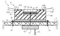
図2および図4に示すように、電極ユニット8は、ゴム電極部14、導電性ゴムコーティング20A,20B、導電性布22、および絶縁性布28を備える。 As shown in FIGS. 2 and 4, the
ゴム電極部14は、導電体を含有するゴムで形成されている。導電体としては、例えば炭素粒子であってもよいし、金属粒子であってもよいし、その他の導電体粒子であってもよい。ゴムとしては、例えばシリコーンゴムであってよい。 The
ゴム電極部14は、互いに離間した一対の厚肉部分15A,15Bと、厚肉部分15A,15Bの間に配置された薄肉部分15Cとを有する。薄肉部分15Cの支持部材2側の面と、厚肉部分15A,15Bの支持部材2側の面は面一である。図2に示すように、生体測定電極装置1の使用時において、厚肉部分15A,15Bの支持部材2とは反対側の面が、被験者(生体)の腕Hに向けられ、薄肉部分15Cは、厚肉部分15A,15Bよりも腕Hから遠くに位置することになる。 The
図1、図2および図4から理解されるように、厚肉部分15A,15Bと薄肉部分15Cの各々は、矩形の板である。厚肉部分15A,15Bの各矩形の一辺の長さは5~20mmであり、他辺の長さも5~20mmである。厚肉部分15A,15B同士の間隔(電極ユニット8の長手方向における薄肉部分15Cの長さ)は、被験者の腕Hの損傷の程度、腕Hの太さ、またはその他の要因によって変わりうる。厚肉部分15A,15Bの厚さは、約1mmであり、薄肉部分15Cの厚さは、約0.5mmである。但し、各部分の形状は、矩形には限定されず、寸法も限定されない。 As can be seen from FIGS. 1, 2 and 4, each of the
このようなゴム電極部14は、例えば、ゴム電極部14全体の形状に対応する内部空間を有する型を用いて、プレス成形または射出成形によって、形成してもよい。あるいは、1つの広い部品14Cに一対の部品14A,14Bを重ねて、ゴム電極部14を形成してもよい。図2において、符号Bで特定される仮想線は、部品14Cの一面、すなわち部品14A,14Bに対する境界面を示す。 Such a
導電性ゴムコーティング20A,20Bが、それぞれ厚肉部分15A,15Bに重ねられている。すなわち、ゴム電極部14の支持部材2とは反対側の面には、導電性ゴムコーティング20A,20Bが接触している。図2に示すように、生体測定電極装置1の使用時において、導電性ゴムコーティング20A,20Bが、腕Hに接触させられる。実施形態において、導電性ゴムコーティング20A,20Bの形状、電極ユニット8の長手方向における長さ、および電極ユニット8の幅方向における長さは、厚肉部分15A,15Bと同じである。導電性ゴムコーティング20A,20Bの厚さは、0.03~0.1mmである。但し、導電性ゴムコーティング20A,20Bの形状は、矩形には限定されず、寸法も限定されない。 The
導電性ゴムコーティング20A,20Bは、導電体を含有するゴムで形成され、ゴム電極よりも低い面抵抗率を有する。導電体としては、例えば銀粒子、塩化銀粒子、金粒子、銅粒子、またはこれらのいずれかの組合せであってよい。ゴムとしては、例えばシリコーンゴムであってよい。ゴム電極部14および導電性ゴムコーティング20A,20Bの材料の好ましい例としては、国際公開第2018/008688号に記載されている材料を使用してよい。 The
図2および図4に示すように、ゴム電極部14の薄肉部分15Cの支持部材2とは反対側には、導電性布22が配置されている。導電性布22は、導電性接着剤24によって、薄肉部分15Cの支持部材2とは反対側の面に接合されている。また、導電性布22の両端部は、それぞれゴム電極部14の厚肉部分15A,15Bに接触し、厚肉部分15A,15Bに導通している。導電性布22の厚さは、限定されないが、例えば、0.1mmである。 As shown in FIGS. 2 and 4, the
導電性布22は、ゴム電極部14よりも高い導電率を有する。例えば、導電性布22の基材は、綿または合成繊維から形成されている。基材は、織布でも、不織布でも、網でもよい。導電性布22は、例えば、銀粒子、金粒子などの金属粒子または金属化合物粒子を含有する導電性シリコーンゴムを基材に含浸させ硬化させることにより、形成することができる。導電性接着剤24は、例えば、銀粒子、金粒子などの金属粒子または金属化合物粒子を含有するエポキシ樹脂である。 The
ゴム電極部14の支持部材2側には、絶縁性布28が配置されている。したがって、図2に示すように、電極ユニット8を支持部材2に取り付けると、絶縁性布28は、ゴム電極部14と支持部材2との間に配置される。絶縁性布28は、ゴム電極部14よりも大きな面積を有しており、ゴム電極部14の支持部材2側の面全体を覆う。絶縁性布28は、絶縁性接着剤30によって、ゴム電極部14に接合されている。絶縁性布28は、綿または合成繊維から形成されている。絶縁性布28は、織布でも、不織布でも、網でもよい。絶縁性接着剤30は、例えば、エポキシ樹脂を含有する接着剤である。 An insulating
図2に示すように、上記構成の電極ユニット8は、縫製糸35,36によって、支持部材2に固定されている。具体的には、電極ユニット8の絶縁性布28が、縫製糸35,36を用いた縫製によって、支持部材2に固定されている。縫製糸35,36の各縫い目は、絶縁性布28と支持部材2を貫通する。 As shown in FIG. 2, the
電極ユニット8と、電極ユニット8に対応する信号処理回路10との電気的接続は、1本の導電性糸32によって達成されている。導電性糸32は、導電性布22、導電性接着剤24、ゴム電極部14の薄肉部分15C、絶縁性接着剤30、絶縁性布28、および支持部材2を貫通し、ゴム電極部14と信号処理回路10とを電気的に接続する。生体測定電極装置1の製造時に、例えば、縫い針(図示せず)を用いて、導電性糸32が上記の所要の要素を貫通するように縫うことによって、容易に生体測定電極装置1を製造することができる。 The electrical connection between the
導電性糸32の一端部には、結び目(糸コブ、ノット)34が形成されている。結び目34は導電性布22の表面に接触させられる。導電性糸32の他端部は、例えば、導電性接着剤または半田で信号処理回路10に固定されている。したがって、電極ユニット8と支持部材2に対する導電性糸32の相対的な移動が抑制されている。結び目34を接着剤で導電性布22に固定してもよい。 A knot (thread bump, knot) 34 is formed at one end of the
電極ユニット8の2箇所、すなわち2つの導電性ゴムコーティング20A,20Bが腕Hに接触させられるが、電極ユニット8には1本の導電性糸32だけが設けられている。したがって、生体測定電極装置1の使用時において、信号処理回路10には、2つの導電性ゴムコーティング20A,20Bに由来する電気信号が合成されて、合成された電気信号が導電性糸32を通じて供給される。 Two places of the
信号処理回路10は、合成された電気信号を受けて当該電気信号を処理する。具体的には、信号処理回路10は、例えば、電気信号のノイズキャンセル処理と増幅処理を実行する。 The
ノイズキャンセル処理と増幅処理が施された電気信号は、リード線12を通じて、図示しない測定ユニットに供給される。測定ユニットは、複数の信号処理回路10から供給された電気信号の電位、すなわち腕の複数の表面筋電位を測定する。 The electric signal subjected to the noise canceling process and the amplification process is supplied to a measurement unit (not shown) through the
導電性糸32は、ゴム電極部14よりも高い導電率を有する。導電性糸32は、例えば、銅またはステンレス鋼により形成されている。したがって、電気信号の伝達性を向上させることができる。導電性糸32は、撚糸でもよいが、好ましくは単糸であり、より好ましくは長手方向における異なる断面が一様な形状(例えば円形)と一様な断面積を有する。 The
導電性糸32だけでなく導電性布22も、ゴム電極部14よりも高い導電率を有する。したがって、図2および図3に点線で例示する電気信号の主経路Pが得られる。主経路Pは、2つの導電性ゴムコーティング20A,20Bから出発し、ゴム電極部14の2つの厚肉部分15A,15Bを経て、導電性布22で合流し、導電性糸32を経て、信号処理回路10に至る。ゴム電極部14の全体と導電性接着剤24も導電性を有するので、当然ながら、主経路P以外にも多くの電気信号の経路があるが、主経路Pは最も電流が流れやすい経路である。 Not only the
ゴム電極部14の薄肉部分15Cの上には、導電性糸32の端部の結び目34と導電性布22とを覆う絶縁性コーティング26が配置されている。絶縁性コーティング26は、ゴム電極部14の厚肉部分15A,15Bの支持部材2とは反対側の面よりも、支持部材2の近くに配置されている。絶縁性コーティング26は、接着剤で導電性布22に固定してもよい。 An insulating
絶縁性コーティング26は、例えばシリコーン樹脂から形成されている。絶縁性コーティング26の厚さは、限定されないが、例えば、0.1mmである。 The insulating
この生体測定電極装置1の製造においては、まずゴム電極部14を上記の通り作成する。そして、ゴム電極部14の厚肉部分15A,15Bに、導電性ゴムコーティング20A,20Bを積層させる。例えば、国際公開第2018/008688号に記載されているように、導電体粒子を含有するシリコーンゴムペーストを塗布し、次いで、シリコーンゴムペーストを硬化させてよい。 In the manufacture of the
さらに、ゴム電極部14の薄肉部分15Cに、導電性接着剤24によって導電性布22を接合する。そして、ゴム電極部14の他面に、絶縁性接着剤30によって絶縁性布28を接合する。このようにして、図4に示す電極ユニット8が完成する。 Further, the
次に、図2に示すように、電極ユニット8を支持部材2に載せる。そして、例えば、縫い針を用いて、導電性糸32を導電性布22、導電性接着剤24、ゴム電極部14の薄肉部分15C、絶縁性接着剤30、絶縁性布28、および支持部材2に貫通させる。さらに、導電性糸32の端部に、導電性糸32の抜け止めとして結び目34を形成する。結び目34を接着剤で導電性布22に固定してもよい。あるいは、結び目34を形成せずに、導電性糸32の端部を接着剤で導電性布22に固定してもよい。このようにして、電極ユニット8と信号処理回路10が、電気的にも機械的にも接続される。 Next, as shown in FIG. 2, the
次に、導電性糸32の他端部を、例えば、導電性接着剤または半田で信号処理回路10に固定する。さらに、縫製糸35,36を用いた縫製によって、電極ユニット8の絶縁性布28を支持部材2に固定する。このようにして、支持部材2に電極ユニット8が固定される。必要な数の電極ユニット8と信号処理回路10を支持部材2に取り付けることにより、生体測定電極装置1が完成する。 Next, the other end of the
この実施形態では、ゴム電極部14と導電性ゴムコーティング20A,20Bを生体に向けて、生体測定電極装置1を使用することができる。ゴム電極部14と導電性ゴムコーティング20A,20Bは、ゴム弾性を有するため、生体から力を受けると生体の輪郭に順応して変形するため、ゴム電極部14自体で、生体への広い対向面積を安定して確保することができ、導電性ゴムコーティング20A,20B自体で、生体への広い接触面積を安定して確保することができる。このため、導電性ゲルまたは導電性クリームを使用することが必要ではなく、生体に不快感を与えることが少ない。また、ゴム電極部14と導電性ゴムコーティング20A,20Bは、硬さが低く、熱伝導率が低いため、生体に与える不快感が少ない。さらにゴム電極部14と導電性ゴムコーティング20A,20Bは、導電性ゲルまたは導電性クリームに比べて、性質が安定しているため、長時間または繰り返し使用することができる。 In this embodiment, the
ゴム電極部14と信号処理回路10との電気的接続には、ゴム電極部14と支持部材2とを貫通する導電性糸32が使用される。生体測定電極装置1の製造時に、例えば縫い針を用いて、導電性糸32がゴム電極部14と支持部材2とを貫通するように縫うことによって、容易に生体測定電極装置1を製造することができる。 A
支持部材2は、生体の部位に接触させられる布、皮革または合成皮革である。したがって、生体測定電極装置1の製造時に、導電性糸32が布、皮革または合成皮革である支持部材2を容易に貫通することができる。 The
導電性糸32は、ゴム電極部14よりも高い導電率を有する。したがって、電気信号の伝達性を向上させることができる。 The
ゴム電極部14は、薄肉部分15Cと厚肉部分15A,15Bを有しており、薄肉部分15Cの支持部材2側の面と、厚肉部分15A,15Bの支持部材2側の面は面一である。生体測定電極装置1の使用時に、厚肉部分15A,15Bが生体に向けられ、薄肉部分15Cを貫通する導電性糸32が生体に接触するおそれが少ない。したがって、導電性糸32が生体に接触することにより生じうるノイズの発生が防止されるか、ノイズの発生の頻度が低減する。 The
また、互いに離間した厚肉部分15A,15Bの間に、薄肉部分15Cが配置されているので、薄肉部分15Cを貫通する導電性糸32が生体に接触するおそれが少ない。したがって、導電性糸32が生体に接触することにより生じうるノイズの発生が防止されるか、ノイズの発生の頻度が低減する。さらに、薄肉部分15Cを挟んで互いに離間した厚肉部分15A,15Bが生体に向けられるため、生体測定電極装置1の接触圧が厚肉部分15A,15Bでバランスよく均一化され、生体への接触状態が安定し、電気信号が安定する。 Further, since the thin-
ゴム電極部14の薄肉部分15Cの支持部材2とは反対側には、布(この実施形態では導電性布22)が配置されており、導電性糸32は、ゴム電極部14の薄肉部分15Cを覆う布と薄肉部分15Cを貫通する。ゴム電極部14が低い強度の材料で形成されていたとしても、薄肉部分15Cを覆う布で薄肉部分15Cが補強されているので、生体測定電極装置1の製造時に、例えば縫い針を用いて導電性糸32を薄肉部分15Cに貫通させても、薄肉部分15Cの裂けを防止または低減することができる。 A cloth (
この実施形態では、その布は、ゴム電極部14よりも高い導電率を有する導電性布22であり、ゴム電極部14の厚肉部分15A,15Bに導通している。したがって、主経路Pの説明として上記した通り、生体測定電極装置1の使用時に、電気信号の大部分は、ゴム電極部14の厚肉部分15A,15Bから導電性布22を経て、導電性糸32を通り、信号処理回路10に安定的に伝達される。第1実施形態のこの効果については、第2実施形態に関連して、詳しく後述する。 In this embodiment, the cloth is a
導電性布22は、導電性接着剤24によって、ゴム電極部14の薄肉部分15Cに接合されている。導電性接着剤24によって、導電性布22と薄肉部分15Cの導電状態が安定するので、電気信号が信号処理回路10に安定的に伝達される。 The
この実施形態では、導電性糸32の端部と導電性布22とを覆う絶縁性コーティング26が配置されている。したがって、生体測定電極装置1の使用時に、絶縁性コーティング26によって導電性糸32と導電性布22が生体に接触するおそれが排除され、導電性糸32と導電性布22が生体に接触することにより生じうるノイズの発生が防止される。 In this embodiment, an insulating
絶縁性コーティング26は、厚肉部分15A,15Bの支持部材2とは反対側の面よりも、支持部材2の近くに配置されている。すなわち、生体測定電極装置1の使用時に、絶縁性コーティング26は、生体から離間することになり、厚肉部分15A,15Bの生体への接触を阻害しない。したがって、厚肉部分15A,15Bの生体への広い対向面積を安定的に確保することができる。 The insulating
ゴム電極部14と支持部材2との間には、絶縁性布28が配置されており、導電性糸32は、ゴム電極部14と絶縁性布28と支持部材2とを貫通する。ゴム電極部14が低い強度の材料で形成されていたとしても、絶縁性布28でゴム電極部14が補強されているので、生体測定電極装置1の製造時に、例えば縫い針を用いて導電性糸32をゴム電極部14に貫通させても、ゴム電極部14の裂けを防止または低減することができる。また、導電性糸32がゴム電極部14と絶縁性布28を貫通した後、導電性糸32が支持部材2を貫通する前に、導電性糸32に横方向の力が与えられたとしても、導電性糸32が貫通する絶縁性布28で導電性糸32の横移動が抑制されるため、ゴム電極部14の裂けを防止または低減することができる。絶縁性布28は絶縁性であるから、生体測定電極装置1の使用時に、絶縁性布28は、導電性糸32を通って伝達される電気信号にノイズを与えない。 An insulating
絶縁性布28は、ゴム電極部14に接合されている。したがって、絶縁性布28とゴム電極部14を有する電極ユニット8を、支持部材2に取り付ける前に、1つのブロックとして、取り扱うことができ、管理および運搬が容易である。また、生体測定電極装置1の製造時に、導電性糸32がゴム電極部14と絶縁性布28を貫通した後、導電性糸32が支持部材2を貫通する前に、絶縁性布28がゴム電極部14および導電性糸32から脱落することが防止される。この実施形態では、絶縁性接着剤30によって、絶縁性布28がゴム電極部14に接合されているが、他の取付け手段、例えばネジまたはステープルで、絶縁性布28がゴム電極部14に接合されてもよい。 The insulating
絶縁性布28は、支持部材2に縫製糸35,36で固定されている。したがって、生体測定電極装置1の製造時に、絶縁性布28を支持部材2に縫製糸35,36で縫製することにより、容易に固定することができる。但し、他の取付け手段、例えばネジまたはステープルで、絶縁性布28が支持部材2に固定されてもよい。 The insulating
ゴム電極部14の支持部材2とは反対側の面には、導電性ゴムコーティング20A,20Bが接触しており、導電性ゴムコーティング20A,20Bは、導電体を含有するゴムで形成され、ゴム電極部14よりも低い面抵抗率を有する。面抵抗率が低い導電性ゴムコーティング20A,20Bを生体に接触させることによって、生体からゴム電極への導電性が向上し、生体からゴム電極への導電状態が安定するので、電気信号が信号処理回路10に安定的に伝達される。 The
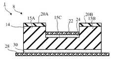
第2実施形態
図5は、本発明の第2実施形態に係る生体測定電極装置1を示す。図5は、図2と同様に、図1のII-II線矢視断面図である。図5以降の図面において、すでに説明した構成要素を示すため、同一の符号が使用され、それらの構成要素については詳細には説明しない。Second Embodiment FIG. 5 shows a
この実施形態では、電極ユニット8の代わりに電極ユニット40が設けられている。電極ユニット40においては、第1実施形態の導電性布22の代わりに絶縁性布42が設けられ、導電性接着剤24の代わりに絶縁性接着剤44が設けられている。具体的には、ゴム電極部14の薄肉部分15Cの支持部材2とは反対側には、絶縁性布42が配置されている。絶縁性布42は、絶縁性接着剤44によって、薄肉部分15Cの支持部材2とは反対側の面に接合されている。また、絶縁性布42の両端部は、それぞれゴム電極部14の厚肉部分15A,15Bに接触していてもよいし、接触していなくてもよい。絶縁性布42の厚さは、限定されないが、例えば、0.1mmである。 In this embodiment, the
第2実施形態に係る生体測定電極装置1の製造においては、第1実施形態と同じく、まずゴム電極部14を上記の通り作成し、ゴム電極部14の厚肉部分15A,15Bに、導電性ゴムコーティング20A,20Bを積層させる。 In the manufacture of the
さらに、ゴム電極部14の薄肉部分15Cに、絶縁性接着剤44によって絶縁性布42を接合する。そして、ゴム電極部14の他面に、絶縁性接着剤30によって絶縁性布28を接合する。このようにして、電極ユニット40が完成する。 Further, the insulating
次に、図電極ユニット40を支持部材2に載せる。そして、例えば、縫い針を用いて、導電性糸32を絶縁性布42、絶縁性接着剤44、ゴム電極部14の薄肉部分15C、絶縁性接着剤30、絶縁性布28、および支持部材2に貫通させる。さらに、導電性糸32の端部に、導電性糸32の抜け止めとして結び目34を形成する。結び目34を接着剤で絶縁性布42に固定してもよい。あるいは、結び目34を形成せずに、導電性糸32の端部を接着剤で絶縁性布42に固定してもよい。このようにして、電極ユニット40と信号処理回路10が、電気的にも機械的にも接続される。 Next, the
次に、導電性糸32の他端部を、例えば、導電性接着剤または半田で信号処理回路10に固定する。さらに、縫製糸35,36を用いた縫製によって、電極ユニット40の絶縁性布28を支持部材2に固定する。このようにして、支持部材2に電極ユニット40が固定される。必要な数の電極ユニット40と信号処理回路10を支持部材2に取り付けることにより、生体測定電極装置1が完成する。 Next, the other end of the
導電性糸32の端部の結び目34は、厚肉部分15A,15Bの支持部材2とは反対側の面よりも、支持部材2の近くに配置されている。すなわち、生体測定電極装置1の使用時に、導電性糸32は、生体(ここでは被験者の腕H)から離間することになり、厚肉部分15A,15Bの生体への接触を阻害しない。したがって、厚肉部分15A,15Bの生体への広い対向面積を安定的に確保することができる。また、導電性糸32は、生体から離間することになるため、導電性糸32が生体に接触することにより生じうるノイズの発生が防止されるか、ノイズの発生の頻度が低減する。 The
この実施形態では、第1実施形態の導電性布22の代わりに絶縁性布42が使用されているので、第1実施形態の絶縁性コーティング26は設けられていない。但し、導電性糸32が生体に接触するのを確実に防止するため、絶縁性コーティング26または絶縁性接着剤などの絶縁体で導電性糸32の端部を覆ってもよい。 In this embodiment, since the insulating
この実施形態によれば、上記の第1実施形態の効果と同じ様々な効果を達成することができる。但し、信号処理回路10に供給される電気信号の安定性に関しては、第1実施形態が第2実施形態より優れている。この点に関して、次に詳述する。 According to this embodiment, the same various effects as those of the above-mentioned first embodiment can be achieved. However, the first embodiment is superior to the second embodiment in terms of the stability of the electric signal supplied to the
この実施形態では、薄肉部分15Cに重ねられた布42および接着剤44が絶縁性である。したがって、図5および図6に点線で例示する電気信号の主経路Pが得られる。主経路Pは、2つの導電性ゴムコーティング20A,20Bから出発し、ゴム電極部14の2つの厚肉部分15A,15Bを経て、導電性糸32で合流し、導電性糸32を経て、信号処理回路10に至る。ゴム電極部14の全体が導電性を有するので、当然ながら、主経路P以外にも多くの電気信号の経路があるが、主経路Pは最も電流が流れやすい経路である。 In this embodiment, the
この実施形態では、薄肉部分15Cを覆う布42が絶縁性であるので、生体測定電極装置1の使用時に、電気信号の大部分は、ゴム電極部14の厚肉部分15A,15Bから導電性糸32を経て、信号処理回路10に伝達されるが、薄肉部分15Cを貫通する導電性糸32と薄肉部分15Cの接触状態によっては、電気信号が信号処理回路10に安定的に伝達されないおそれや、電気信号にノイズが混入するおそれがある。図6に拡大して示すように、薄肉部分15Cには、導電性糸32を貫通させるために形成された貫通孔46が形成され、貫通孔46の内径は、導電性糸32の外径よりもわずかに大きい。したがって、導電性糸32の長手方向において、導電性糸32と薄肉部分15Cに接触する位置が、人体の動きなどの外力に起因するゴム電極部14の動きまたは変形によって、容易に変わりうる。例えば、図6に例示する右側の信号の主経路Pは、常に一定位置にあるとは限らず、左側の信号の主経路Pも、常に一定位置にあるとは限らない。この接触状態の不安定性が電気信号の不安定性またはノイズの原因となりうる。 In this embodiment, since the
一方、第1実施形態では、図2および図3に示すように、薄肉部分15Cを覆う布がゴム電極部14よりも高い導電率を有する導電性布22であり、ゴム電極部14の厚肉部分15A,15Bに導通している。このため、生体測定電極装置1の使用時に、電気信号の大部分は、図2および図3で信号の主経路Pとして示すように、ゴム電極部14の厚肉部分15A,15Bから導電性布22を経て、導電性糸32を通り、信号処理回路10に安定的に伝達される。図3に拡大して示すように、薄肉部分15Cには、導電性糸32を貫通させるために形成された貫通孔46が形成され、貫通孔46の内径は、導電性糸32の外径よりもわずかに大きい。しかし、導電性布22は、繊維から形成されているので、導電性糸32の全周にわたって、さらには導電性糸32の長手方向において、均一に接触する。このため、ゴム電極部14の動きまたは変形があっても、図3に例示する右側の信号の主経路Pは、常にほぼ一定の位置にあり、左側の信号の主経路Pも、常にほぼ一定の位置にある。この信号の主経路の不変性のため、電気信号は安定的に伝達される。 On the other hand, in the first embodiment, as shown in FIGS. 2 and 3, the cloth covering the thin-
第3実施形態
図7は、本発明の第3実施形態に係る生体測定電極装置1を示す。図7は、図2と同様に、図1のII-II線矢視断面図である。Third Embodiment FIG. 7 shows a
この実施形態では、電極ユニット8の代わりに電極ユニット50が設けられている。電極ユニット50は、ゴム電極部14のみから構成されている。また、ゴム電極部14には、1つの厚肉部分15Aのみが形成されている。導電性糸32は、ゴム電極部14の薄肉部分15Cと支持部材2を貫通して、ゴム電極部14と信号処理回路10を電気的および機械的に接続する。 In this embodiment, the
この実施形態では、ゴム電極部14を生体に接触させて、生体測定電極装置1を使用することができる。ゴム電極部14は、ゴム弾性を有するため、生体から力を受けると生体の輪郭に順応して変形するため、ゴム電極部14自体で、生体への広い接触面積を安定して確保することができる。このため、導電性ゲルまたは導電性クリームを使用することが必要ではなく、生体に不快感を与えることが少ない。また、ゴム電極部14は、硬さが低く、熱伝導率が低いため、生体に与える不快感が少ない。さらにゴム電極部14は、導電性ゲルまたは導電性クリームに比べて、性質が安定しているため、長時間または繰り返し使用することができる。 In this embodiment, the
ゴム電極部14と信号処理回路10との電気的接続には、ゴム電極部14と支持部材2とを貫通する導電性糸32が使用される。生体測定電極装置1の製造時に、例えば縫い針を用いて、導電性糸32がゴム電極部14と支持部材2とを貫通するように縫うことによって、容易に生体測定電極装置1を製造することができる。 A
第4実施形態
図8は、本発明の第4実施形態に係る生体測定電極装置1を示す。図8は、図1と同様に、生体測定電極装置1の斜視図である。図8の点線の矩形内の図は、図8のVIII-VIII線矢視断面図である。Fourth Embodiment FIG. 8 shows a
第4実施形態においては、ゴム電極部14の代わりにゴム電極部64が設けられ、導電性ゴムコーティング20A,20Bの代わりに、導電性ゴムコーティング66が設けられている。ゴム電極部64は、円環形または楕円環形の厚肉部分65Aと、円形または楕円形の薄肉部分65Bを有する。円環形または楕円環形の導電性ゴムコーティング66が厚肉部分65Aに重ねられている。 In the fourth embodiment, the
ゴム電極部64の材料は、ゴム電極部14と同じでよい。導電性ゴムコーティング66の材料は、導電性ゴムコーティング20A,20Bと同じでよい。 The material of the
ゴム電極部64は、例えば、ゴム電極部64全体の形状に対応する内部空間を有する型を用いて、プレス成形または射出成形によって、形成してもよい。あるいは、1つの円板または楕円板に1つの円環形または楕円環形の部品を重ねて、ゴム電極部64を形成してもよい。 The
生体測定電極装置1の使用時においては、円環形または楕円環形の導電性ゴムコーティング66が、腕Hに接触させられる。薄肉部分65B、ならびにその上の導電性布22、導電性接着剤24、および絶縁性コーティング26は、腕Hに接触しない。 When using the
この実施形態では、ゴム電極部64と導電性ゴムコーティング66を生体に向けて、生体測定電極装置1を使用することができる。ゴム電極部64と導電性ゴムコーティング66は、ゴム弾性を有するため、生体から力を受けると生体の輪郭に順応して変形するため、ゴム電極部64自体で、生体への広い対向面積を安定して確保することができ、導電性ゴムコーティング66自体で、生体への広い接触面積を安定して確保することができる。このため、導電性ゲルまたは導電性クリームを使用することが必要ではなく、生体に不快感を与えることが少ない。また、ゴム電極部64と導電性ゴムコーティング66は、硬さが低く、熱伝導率が低いため、生体に与える不快感が少ない。さらにゴム電極部64と導電性ゴムコーティング66は、導電性ゲルまたは導電性クリームに比べて、性質が安定しているため、長時間または繰り返し使用することができる。 In this embodiment, the
ゴム電極部64と信号処理回路10との電気的接続には、ゴム電極部64の薄肉部分65Bと支持部材2とを貫通する導電性糸32が使用される。生体測定電極装置1の製造時に、例えば縫い針を用いて、導電性糸32がゴム電極部64と支持部材2とを貫通するように縫うことによって、容易に生体測定電極装置1を製造することができる。 For the electrical connection between the
他の変形例
以上、本発明の実施形態を説明したが、上記の説明は本発明を限定するものではなく、本発明の技術的範囲において、構成要素の削除、追加、置換を含む様々な変形例が考えられる。Other Modifications Although the embodiments of the present invention have been described above, the above description does not limit the present invention, and various modifications including deletion, addition, and replacement of components are included in the technical scope of the present invention. An example is possible.
実施形態に係る生体測定電極装置は、例示として、人間の被験者の腕の複数の部位の表面筋電位を測定するために使用される。しかし、本発明に係る生体測定電極装置は、人間以外の生体にも使用可能である。 The biometric electrode device according to the embodiment is used, for example, to measure the surface myoelectric potential of a plurality of parts of the arm of a human subject. However, the biometric electrode device according to the present invention can be used for living organisms other than humans.
また、本発明に係る生体測定電極装置は、生体の下肢の複数の部位の表面筋電位を測定するために使用してもよい。測定された下肢の表面筋電位は、例えば、筋電義足の動きの制御に使用されうる。 Further, the biometric electrode device according to the present invention may be used to measure the surface myoelectric potential of a plurality of parts of the lower limbs of the living body. The measured lower limb surface myoelectric potential can be used, for example, to control the movement of the myoelectric prosthetic hand.
また、本発明に係る生体測定電極装置は、生体の頭部または頸部の表面電位を測定するために使用してもよい。測定された頭部の表面電位は、例えば、脳波の変化の推定に使用されうる。 Further, the biometric electrode device according to the present invention may be used for measuring the surface potential of the head or neck of a living body. The measured surface potential of the head can be used, for example, to estimate changes in EEG.
また、本発明に係る生体測定電極装置は、生体の胴部または腹部の表面電位を測定するために使用してもよい。測定された各種の部位の表面電位は、例えば、心電図波形、肺活量、または体脂肪率の推定に使用されうる。 Further, the biometric electrode device according to the present invention may be used for measuring the surface potential of the body or abdomen of a living body. The measured surface potentials of the various sites can be used, for example, to estimate electrocardiographic waveforms, vital capacity, or body fat percentage.
1 生体測定電極装置
2 支持部材
4,6 ファスナー
8,40,50,60 電極ユニット
10 信号処理回路
12 リード線
14,64 ゴム電極部
15A,15B,65A 厚肉部分
15C,65B 薄肉部分
20A,20B,66 導電性ゴムコーティング
22 導電性布
24 導電性接着剤
26 絶縁性コーティング
28 絶縁性布
30 絶縁性接着剤
32 導電性糸
34 結び目
35,36 縫製糸
42 絶縁性布
44 絶縁性接着剤
46 貫通孔
H 被験者(生体)の腕
P 信号の主経路1
Claims (10)
Translated fromJapanese前記ゴム電極部からの電気信号を受けて当該電気信号を処理する信号処理回路と、
前記ゴム電極部が一方の面側に配置され、前記信号処理回路が他方の面側に配置された支持部材と、
前記ゴム電極部と前記支持部材とを貫通し、前記ゴム電極部と前記信号処理回路とを電気的に接続する導電性糸と
を備え、
前記ゴム電極部は、薄肉部分と、前記薄肉部分の両側に配置された厚肉部分を有しており、
前記薄肉部分の前記支持部材側の面と、前記厚肉部分の前記支持部材側の面は面一であり、
前記薄肉部分の生体側の面は、前記厚肉部分の生体側の面よりも凹んでおり、
前記導電性糸は、前記薄肉部分と前記支持部材とを貫通する
ることを特徴とする生体測定電極装置。A rubber electrode part made of rubber containing a conductor and
A signal processing circuit that receives an electric signal from the rubber electrode portion and processes the electric signal,
A support member in which the rubber electrode portion is arranged on one surface side and the signal processing circuit is arranged on the other surface side.
A conductive thread that penetrates the rubber electrode portion and the support member and electrically connects the rubber electrode portion and the signal processing circuit is provided.
The rubber electrode portion has a thin-walled portion and thick-walled portions arranged on both sides of the thin-walled portion.
The surface of the thin-walled portion on the support member side and the surface of the thick-walled portion on the support member side are flush with each other.
The surface of the thin-walled portion on the living body side is recessed from the surface of the thick-walled portion on the living body side.
The conductive thread penetrates the thin-walled portion and the support member.
A biometric electrode device characterized by the above.
前記ゴム電極部からの電気信号を受けて当該電気信号を処理する信号処理回路と、
前記ゴム電極部が一方の面側に配置され、前記信号処理回路が他方の面側に配置された支持部材と、
前記ゴム電極部と前記支持部材とを貫通し、前記ゴム電極部と前記信号処理回路とを電気的に接続する導電性糸と
を備え、
前記ゴム電極部は、薄肉部分と厚肉部分を有しており、
前記薄肉部分の前記支持部材側の面と、前記厚肉部分の前記支持部材側の面は面一であり、
前記ゴム電極部の前記薄肉部分の前記支持部材とは反対側には、布が配置されており、
前記導電性糸は、前記布と前記薄肉部分と前記支持部材とを貫通する
ることを特徴とする生体測定電極装置。A rubber electrode part made of rubber containing a conductor and
A signal processing circuit that receives an electric signal from the rubber electrode portion and processes the electric signal,
A support member in which the rubber electrode portion is arranged on one surface side and the signal processing circuit is arranged on the other surface side.
A conductive thread that penetrates the rubber electrode portion and the support member and electrically connects the rubber electrode portion and the signal processing circuit is provided.
The rubber electrode portion has a thin-walled portion and a thick-walled portion.
The surface of the thin-walled portion on the support member side and the surface of the thick-walled portion on the support member side are flush with each other.
A cloth is arranged on the opposite side of the thin-walled portion of the rubber electrode portion from the support member.
The conductive thread penetrates the cloth, the thin portion, and the support member.
A biometric electrode device characterized by the above.
ことを特徴とする請求項2に記載の生体測定電極装置。2. The biometric electrode device according to claim 2.
ことを特徴とする請求項3に記載の生体測定電極装置。The biometric electrode device according to claim 3.
ことを特徴とする請求項4に記載の生体測定電極装置。The biometric electrode device according to claim 4.
ことを特徴とする請求項1から5のいずれか1項に記載の生体測定電極装置。The biometric electrode device according toany one of claims 1 to 5, wherein the support member is a cloth, leather or synthetic leather that is brought into contact with a part of a living body.
ことを特徴とする請求項1から6のいずれか1項に記載の生体測定電極装置。The biometric electrode device according toany one of claims 1 to 6, wherein the conductive thread has a higher conductivity than that of the rubber electrode portion.
前記導電性糸は、前記ゴム電極部と前記絶縁性布と前記支持部材とを貫通する
ことを特徴とする請求項1から7のいずれか1項に記載の生体測定電極装置。An insulating cloth is arranged between the rubber electrode portion and the support member.
The biometric electrode device according to any one of claims 1 to7 , wherein the conductive thread penetrates the rubber electrode portion, the insulating cloth, and the support member.
ことを特徴とする請求項8に記載の生体測定電極装置。The biometric electrode device according to claim8 , wherein the insulating cloth is fixed to the support member with a sewing thread.
前記導電性ゴムコーティングは、導電体を含有するゴムで形成され、前記ゴム電極部よりも低い面抵抗率を有する
ことを特徴とする請求項1から9のいずれか1項に記載の生体測定電極装置。A conductive rubber coating is in contact with the surface of the rubber electrode portion on the side opposite to the support member.
The biometric electrode according to any one of claims 1 to9 , wherein the conductive rubber coating is formed of rubber containing a conductor and has a surface resistivity lower than that of the rubber electrode portion. Device.
Priority Applications (1)
| Application Number | Priority Date | Filing Date | Title |
|---|---|---|---|
| JP2018018810AJP7078414B2 (en) | 2018-02-06 | 2018-02-06 | Biometric electrode device |
Applications Claiming Priority (1)
| Application Number | Priority Date | Filing Date | Title |
|---|---|---|---|
| JP2018018810AJP7078414B2 (en) | 2018-02-06 | 2018-02-06 | Biometric electrode device |
Publications (2)
| Publication Number | Publication Date |
|---|---|
| JP2019136055A JP2019136055A (en) | 2019-08-22 |
| JP7078414B2true JP7078414B2 (en) | 2022-05-31 |
Family
ID=67692421
Family Applications (1)
| Application Number | Title | Priority Date | Filing Date |
|---|---|---|---|
| JP2018018810AActiveJP7078414B2 (en) | 2018-02-06 | 2018-02-06 | Biometric electrode device |
Country Status (1)
| Country | Link |
|---|---|
| JP (1) | JP7078414B2 (en) |
Families Citing this family (5)
| Publication number | Priority date | Publication date | Assignee | Title |
|---|---|---|---|---|
| EP3851034A1 (en)* | 2020-01-16 | 2021-07-21 | Pierenkemper GmbH | Device comprising at least one electrode unit for an electrostimulation or a data acquisition of diagnostic devices |
| JP7404975B2 (en)* | 2020-03-31 | 2023-12-26 | オムロンヘルスケア株式会社 | Belt and electrocardiogram measuring device |
| JP2022133931A (en) | 2021-03-02 | 2022-09-14 | ソニーグループ株式会社 | Biopotential measurement electrode and biological information measuring device |
| JP2022150229A (en)* | 2021-03-26 | 2022-10-07 | 三菱ケミカル株式会社 | Connection structure between device and skin, and connection method between device and skin |
| JP2023073775A (en)* | 2021-11-16 | 2023-05-26 | 新光電気工業株式会社 | Bioelectrodes, wearable devices and clothing |
Citations (4)
| Publication number | Priority date | Publication date | Assignee | Title |
|---|---|---|---|---|
| JP2005521458A (en) | 2002-03-29 | 2005-07-21 | コーニンクレッカ フィリップス エレクトロニクス エヌ ヴィ | Monitoring system with electrodes with protrusions |
| JP3153409U (en) | 2009-06-23 | 2009-09-03 | 財団法人大阪バイオサイエンス研究所 | Dry biosignal detection electrode |
| US20090227856A1 (en) | 2007-12-21 | 2009-09-10 | Brian Keith Russell | Electrocardiogram sensor |
| WO2018008688A1 (en) | 2016-07-06 | 2018-01-11 | Nok株式会社 | Bioelectrode and method for producing same |
- 2018
- 2018-02-06JPJP2018018810Apatent/JP7078414B2/enactiveActive
Patent Citations (4)
| Publication number | Priority date | Publication date | Assignee | Title |
|---|---|---|---|---|
| JP2005521458A (en) | 2002-03-29 | 2005-07-21 | コーニンクレッカ フィリップス エレクトロニクス エヌ ヴィ | Monitoring system with electrodes with protrusions |
| US20090227856A1 (en) | 2007-12-21 | 2009-09-10 | Brian Keith Russell | Electrocardiogram sensor |
| JP3153409U (en) | 2009-06-23 | 2009-09-03 | 財団法人大阪バイオサイエンス研究所 | Dry biosignal detection electrode |
| WO2018008688A1 (en) | 2016-07-06 | 2018-01-11 | Nok株式会社 | Bioelectrode and method for producing same |
Also Published As
| Publication number | Publication date |
|---|---|
| JP2019136055A (en) | 2019-08-22 |
Similar Documents
| Publication | Publication Date | Title |
|---|---|---|
| JP7078414B2 (en) | Biometric electrode device | |
| US11101586B2 (en) | Printed circuit board biosensing garment connector | |
| US10925540B2 (en) | Garment with conductive thread exposed on both sides | |
| US5301678A (en) | Stretchable band - type transducer particularly suited for use with respiration monitoring apparatus | |
| US20070285868A1 (en) | Sensor arrangement | |
| US4807640A (en) | Stretchable band-type transducer particularly suited for respiration monitoring apparatus | |
| US20170089782A1 (en) | Strain gauge device and equipment with such strain gauge devices | |
| CN111493817B (en) | Stretchable flexible sensing device | |
| US10595780B2 (en) | Wearable biological information sensing device | |
| US20110251470A1 (en) | Stretchable electrode and method of making physiologic measurements | |
| KR20050088480A (en) | Electrode arrangement | |
| US9986792B2 (en) | Snap button and physiological signal detecting belt thereof for improving electric conductivity | |
| JP6695321B2 (en) | Biomedical electrode tool | |
| CN105377122B (en) | The attachment structure and method of fabric sensor and digital line | |
| JP2018198920A (en) | Biosensor and biosensor manufacturing method | |
| JP2017195230A (en) | Stretchable wiring board and method for manufacturing stretchable wiring board | |
| KR102397139B1 (en) | EEG mesauring head moudle using conductive resin | |
| JP6713921B2 (en) | Wearable device | |
| JPS5830394Y2 (en) | piezoelectric microphone | |
| JP2022547944A (en) | Conductive thread and wearing article containing the thread | |
| US20230274851A1 (en) | Surface electrode | |
| EP4364663A1 (en) | Smart sensing textile | |
| JPS6025259Y2 (en) | Guide for low frequency treatment device | |
| JP2007020654A (en) | Body motion detection belt | |
| WO2025189478A1 (en) | Measurement electrode and wearable device |
Legal Events
| Date | Code | Title | Description |
|---|---|---|---|
| A621 | Written request for application examination | Free format text:JAPANESE INTERMEDIATE CODE: A621 Effective date:20210104 | |
| A977 | Report on retrieval | Free format text:JAPANESE INTERMEDIATE CODE: A971007 Effective date:20211118 | |
| A131 | Notification of reasons for refusal | Free format text:JAPANESE INTERMEDIATE CODE: A131 Effective date:20211130 | |
| A521 | Request for written amendment filed | Free format text:JAPANESE INTERMEDIATE CODE: A523 Effective date:20220107 | |
| TRDD | Decision of grant or rejection written | ||
| A01 | Written decision to grant a patent or to grant a registration (utility model) | Free format text:JAPANESE INTERMEDIATE CODE: A01 Effective date:20220426 | |
| A61 | First payment of annual fees (during grant procedure) | Free format text:JAPANESE INTERMEDIATE CODE: A61 Effective date:20220519 | |
| R150 | Certificate of patent or registration of utility model | Ref document number:7078414 Country of ref document:JP Free format text:JAPANESE INTERMEDIATE CODE: R150 |