JP7077370B2 - Physiological signal monitoring device and its sensor holder - Google Patents
Physiological signal monitoring device and its sensor holderDownload PDFInfo
- Publication number
- JP7077370B2 JP7077370B2JP2020131916AJP2020131916AJP7077370B2JP 7077370 B2JP7077370 B2JP 7077370B2JP 2020131916 AJP2020131916 AJP 2020131916AJP 2020131916 AJP2020131916 AJP 2020131916AJP 7077370 B2JP7077370 B2JP 7077370B2
- Authority
- JP
- Japan
- Prior art keywords
- sensor
- holder
- physiological signal
- embedding hole
- monitoring device
- Prior art date
- Legal status (The legal status is an assumption and is not a legal conclusion. Google has not performed a legal analysis and makes no representation as to the accuracy of the status listed.)
- Active
Links
Images


Classifications
- A—HUMAN NECESSITIES
- A61—MEDICAL OR VETERINARY SCIENCE; HYGIENE
- A61B—DIAGNOSIS; SURGERY; IDENTIFICATION
- A61B5/00—Measuring for diagnostic purposes; Identification of persons
- A61B5/145—Measuring characteristics of blood in vivo, e.g. gas concentration or pH-value ; Measuring characteristics of body fluids or tissues, e.g. interstitial fluid or cerebral tissue
- A61B5/14532—Measuring characteristics of blood in vivo, e.g. gas concentration or pH-value ; Measuring characteristics of body fluids or tissues, e.g. interstitial fluid or cerebral tissue for measuring glucose, e.g. by tissue impedance measurement
- A—HUMAN NECESSITIES
- A61—MEDICAL OR VETERINARY SCIENCE; HYGIENE
- A61B—DIAGNOSIS; SURGERY; IDENTIFICATION
- A61B5/00—Measuring for diagnostic purposes; Identification of persons
- A61B5/0002—Remote monitoring of patients using telemetry, e.g. transmission of vital signals via a communication network
- A61B5/0004—Remote monitoring of patients using telemetry, e.g. transmission of vital signals via a communication network characterised by the type of physiological signal transmitted
- A—HUMAN NECESSITIES
- A61—MEDICAL OR VETERINARY SCIENCE; HYGIENE
- A61B—DIAGNOSIS; SURGERY; IDENTIFICATION
- A61B5/00—Measuring for diagnostic purposes; Identification of persons
- A61B5/145—Measuring characteristics of blood in vivo, e.g. gas concentration or pH-value ; Measuring characteristics of body fluids or tissues, e.g. interstitial fluid or cerebral tissue
- A61B5/14503—Measuring characteristics of blood in vivo, e.g. gas concentration or pH-value ; Measuring characteristics of body fluids or tissues, e.g. interstitial fluid or cerebral tissue invasive, e.g. introduced into the body by a catheter or needle or using implanted sensors
- A—HUMAN NECESSITIES
- A61—MEDICAL OR VETERINARY SCIENCE; HYGIENE
- A61B—DIAGNOSIS; SURGERY; IDENTIFICATION
- A61B5/00—Measuring for diagnostic purposes; Identification of persons
- A61B5/145—Measuring characteristics of blood in vivo, e.g. gas concentration or pH-value ; Measuring characteristics of body fluids or tissues, e.g. interstitial fluid or cerebral tissue
- A61B5/14507—Measuring characteristics of blood in vivo, e.g. gas concentration or pH-value ; Measuring characteristics of body fluids or tissues, e.g. interstitial fluid or cerebral tissue specially adapted for measuring characteristics of body fluids other than blood
- A61B5/1451—Measuring characteristics of blood in vivo, e.g. gas concentration or pH-value ; Measuring characteristics of body fluids or tissues, e.g. interstitial fluid or cerebral tissue specially adapted for measuring characteristics of body fluids other than blood for interstitial fluid
- A—HUMAN NECESSITIES
- A61—MEDICAL OR VETERINARY SCIENCE; HYGIENE
- A61B—DIAGNOSIS; SURGERY; IDENTIFICATION
- A61B5/00—Measuring for diagnostic purposes; Identification of persons
- A61B5/145—Measuring characteristics of blood in vivo, e.g. gas concentration or pH-value ; Measuring characteristics of body fluids or tissues, e.g. interstitial fluid or cerebral tissue
- A61B5/14546—Measuring characteristics of blood in vivo, e.g. gas concentration or pH-value ; Measuring characteristics of body fluids or tissues, e.g. interstitial fluid or cerebral tissue for measuring analytes not otherwise provided for, e.g. ions, cytochromes
- A—HUMAN NECESSITIES
- A61—MEDICAL OR VETERINARY SCIENCE; HYGIENE
- A61B—DIAGNOSIS; SURGERY; IDENTIFICATION
- A61B5/00—Measuring for diagnostic purposes; Identification of persons
- A61B5/145—Measuring characteristics of blood in vivo, e.g. gas concentration or pH-value ; Measuring characteristics of body fluids or tissues, e.g. interstitial fluid or cerebral tissue
- A61B5/1468—Measuring characteristics of blood in vivo, e.g. gas concentration or pH-value ; Measuring characteristics of body fluids or tissues, e.g. interstitial fluid or cerebral tissue using chemical or electrochemical methods, e.g. by polarographic means
- A61B5/1486—Measuring characteristics of blood in vivo, e.g. gas concentration or pH-value ; Measuring characteristics of body fluids or tissues, e.g. interstitial fluid or cerebral tissue using chemical or electrochemical methods, e.g. by polarographic means using enzyme electrodes, e.g. with immobilised oxidase
- A61B5/14865—Measuring characteristics of blood in vivo, e.g. gas concentration or pH-value ; Measuring characteristics of body fluids or tissues, e.g. interstitial fluid or cerebral tissue using chemical or electrochemical methods, e.g. by polarographic means using enzyme electrodes, e.g. with immobilised oxidase invasive, e.g. introduced into the body by a catheter or needle or using implanted sensors
- A—HUMAN NECESSITIES
- A61—MEDICAL OR VETERINARY SCIENCE; HYGIENE
- A61B—DIAGNOSIS; SURGERY; IDENTIFICATION
- A61B5/00—Measuring for diagnostic purposes; Identification of persons
- A61B5/15—Devices for taking samples of blood
- A61B5/150007—Details
- A61B5/150748—Having means for aiding positioning of the piercing device at a location where the body is to be pierced
- A—HUMAN NECESSITIES
- A61—MEDICAL OR VETERINARY SCIENCE; HYGIENE
- A61B—DIAGNOSIS; SURGERY; IDENTIFICATION
- A61B5/00—Measuring for diagnostic purposes; Identification of persons
- A61B5/15—Devices for taking samples of blood
- A61B5/150007—Details
- A61B5/150847—Communication to or from blood sampling device
- A—HUMAN NECESSITIES
- A61—MEDICAL OR VETERINARY SCIENCE; HYGIENE
- A61B—DIAGNOSIS; SURGERY; IDENTIFICATION
- A61B5/00—Measuring for diagnostic purposes; Identification of persons
- A61B5/68—Arrangements of detecting, measuring or recording means, e.g. sensors, in relation to patient
- A61B5/6801—Arrangements of detecting, measuring or recording means, e.g. sensors, in relation to patient specially adapted to be attached to or worn on the body surface
- A61B5/683—Means for maintaining contact with the body
- A61B5/6832—Means for maintaining contact with the body using adhesives
- A61B5/6833—Adhesive patches
- A—HUMAN NECESSITIES
- A61—MEDICAL OR VETERINARY SCIENCE; HYGIENE
- A61B—DIAGNOSIS; SURGERY; IDENTIFICATION
- A61B5/00—Measuring for diagnostic purposes; Identification of persons
- A61B5/68—Arrangements of detecting, measuring or recording means, e.g. sensors, in relation to patient
- A61B5/6846—Arrangements of detecting, measuring or recording means, e.g. sensors, in relation to patient specially adapted to be brought in contact with an internal body part, i.e. invasive
- A61B5/6847—Arrangements of detecting, measuring or recording means, e.g. sensors, in relation to patient specially adapted to be brought in contact with an internal body part, i.e. invasive mounted on an invasive device
- A61B5/6848—Needles
- A61B5/6849—Needles in combination with a needle set
- A—HUMAN NECESSITIES
- A61—MEDICAL OR VETERINARY SCIENCE; HYGIENE
- A61B—DIAGNOSIS; SURGERY; IDENTIFICATION
- A61B5/00—Measuring for diagnostic purposes; Identification of persons
- A61B5/68—Arrangements of detecting, measuring or recording means, e.g. sensors, in relation to patient
- A61B5/6846—Arrangements of detecting, measuring or recording means, e.g. sensors, in relation to patient specially adapted to be brought in contact with an internal body part, i.e. invasive
- A61B5/6867—Arrangements of detecting, measuring or recording means, e.g. sensors, in relation to patient specially adapted to be brought in contact with an internal body part, i.e. invasive specially adapted to be attached or implanted in a specific body part
- A—HUMAN NECESSITIES
- A61—MEDICAL OR VETERINARY SCIENCE; HYGIENE
- A61B—DIAGNOSIS; SURGERY; IDENTIFICATION
- A61B5/00—Measuring for diagnostic purposes; Identification of persons
- A61B5/68—Arrangements of detecting, measuring or recording means, e.g. sensors, in relation to patient
- A61B5/6846—Arrangements of detecting, measuring or recording means, e.g. sensors, in relation to patient specially adapted to be brought in contact with an internal body part, i.e. invasive
- A61B5/6879—Means for maintaining contact with the body
- A61B5/688—Means for maintaining contact with the body using adhesives
- A—HUMAN NECESSITIES
- A61—MEDICAL OR VETERINARY SCIENCE; HYGIENE
- A61B—DIAGNOSIS; SURGERY; IDENTIFICATION
- A61B2560/00—Constructional details of operational features of apparatus; Accessories for medical measuring apparatus
- A61B2560/04—Constructional details of apparatus
- A61B2560/0443—Modular apparatus
- A61B2560/045—Modular apparatus with a separable interface unit, e.g. for communication
- A—HUMAN NECESSITIES
- A61—MEDICAL OR VETERINARY SCIENCE; HYGIENE
- A61B—DIAGNOSIS; SURGERY; IDENTIFICATION
- A61B2560/00—Constructional details of operational features of apparatus; Accessories for medical measuring apparatus
- A61B2560/06—Accessories for medical measuring apparatus
- A61B2560/063—Devices specially adapted for delivering implantable medical measuring apparatus
- A—HUMAN NECESSITIES
- A61—MEDICAL OR VETERINARY SCIENCE; HYGIENE
- A61B—DIAGNOSIS; SURGERY; IDENTIFICATION
- A61B2562/00—Details of sensors; Constructional details of sensor housings or probes; Accessories for sensors
- A61B2562/02—Details of sensors specially adapted for in-vivo measurements
- A61B2562/0295—Strip shaped analyte sensors for apparatus classified in A61B5/145 or A61B5/157
- A—HUMAN NECESSITIES
- A61—MEDICAL OR VETERINARY SCIENCE; HYGIENE
- A61B—DIAGNOSIS; SURGERY; IDENTIFICATION
- A61B2562/00—Details of sensors; Constructional details of sensor housings or probes; Accessories for sensors
- A61B2562/14—Coupling media or elements to improve sensor contact with skin or tissue
- A—HUMAN NECESSITIES
- A61—MEDICAL OR VETERINARY SCIENCE; HYGIENE
- A61B—DIAGNOSIS; SURGERY; IDENTIFICATION
- A61B2562/00—Details of sensors; Constructional details of sensor housings or probes; Accessories for sensors
- A61B2562/16—Details of sensor housings or probes; Details of structural supports for sensors
- A61B2562/166—Details of sensor housings or probes; Details of structural supports for sensors the sensor is mounted on a specially adapted printed circuit board
- A—HUMAN NECESSITIES
- A61—MEDICAL OR VETERINARY SCIENCE; HYGIENE
- A61B—DIAGNOSIS; SURGERY; IDENTIFICATION
- A61B2562/00—Details of sensors; Constructional details of sensor housings or probes; Accessories for sensors
- A61B2562/16—Details of sensor housings or probes; Details of structural supports for sensors
- A61B2562/168—Fluid filled sensor housings
- A—HUMAN NECESSITIES
- A61—MEDICAL OR VETERINARY SCIENCE; HYGIENE
- A61B—DIAGNOSIS; SURGERY; IDENTIFICATION
- A61B2562/00—Details of sensors; Constructional details of sensor housings or probes; Accessories for sensors
- A61B2562/22—Arrangements of medical sensors with cables or leads; Connectors or couplings specifically adapted for medical sensors
- A61B2562/225—Connectors or couplings
- A61B2562/226—Connectors or couplings comprising means for identifying the connector, e.g. to prevent incorrect connection to socket
- A—HUMAN NECESSITIES
- A61—MEDICAL OR VETERINARY SCIENCE; HYGIENE
- A61B—DIAGNOSIS; SURGERY; IDENTIFICATION
- A61B2562/00—Details of sensors; Constructional details of sensor housings or probes; Accessories for sensors
- A61B2562/22—Arrangements of medical sensors with cables or leads; Connectors or couplings specifically adapted for medical sensors
- A61B2562/225—Connectors or couplings
- A61B2562/227—Sensors with electrical connectors
- A—HUMAN NECESSITIES
- A61—MEDICAL OR VETERINARY SCIENCE; HYGIENE
- A61B—DIAGNOSIS; SURGERY; IDENTIFICATION
- A61B2562/00—Details of sensors; Constructional details of sensor housings or probes; Accessories for sensors
- A61B2562/24—Hygienic packaging for medical sensors; Maintaining apparatus for sensor hygiene
- A61B2562/242—Packaging, i.e. for packaging the sensor or apparatus before use
- H—ELECTRICITY
- H01—ELECTRIC ELEMENTS
- H01R—ELECTRICALLY-CONDUCTIVE CONNECTIONS; STRUCTURAL ASSOCIATIONS OF A PLURALITY OF MUTUALLY-INSULATED ELECTRICAL CONNECTING ELEMENTS; COUPLING DEVICES; CURRENT COLLECTORS
- H01R12/00—Structural associations of a plurality of mutually-insulated electrical connecting elements, specially adapted for printed circuits, e.g. printed circuit boards [PCB], flat or ribbon cables, or like generally planar structures, e.g. terminal strips, terminal blocks; Coupling devices specially adapted for printed circuits, flat or ribbon cables, or like generally planar structures; Terminals specially adapted for contact with, or insertion into, printed circuits, flat or ribbon cables, or like generally planar structures
- H01R12/70—Coupling devices
- H01R12/71—Coupling devices for rigid printing circuits or like structures
- H01R12/72—Coupling devices for rigid printing circuits or like structures coupling with the edge of the rigid printed circuits or like structures
- H01R12/73—Coupling devices for rigid printing circuits or like structures coupling with the edge of the rigid printed circuits or like structures connecting to other rigid printed circuits or like structures
- H01R12/735—Printed circuits including an angle between each other
- H01R12/737—Printed circuits being substantially perpendicular to each other
Landscapes
- Health & Medical Sciences (AREA)
- Life Sciences & Earth Sciences (AREA)
- Physics & Mathematics (AREA)
- Engineering & Computer Science (AREA)
- Animal Behavior & Ethology (AREA)
- Veterinary Medicine (AREA)
- Biomedical Technology (AREA)
- Heart & Thoracic Surgery (AREA)
- Public Health (AREA)
- General Health & Medical Sciences (AREA)
- Pathology (AREA)
- Surgery (AREA)
- Molecular Biology (AREA)
- Medical Informatics (AREA)
- Biophysics (AREA)
- Optics & Photonics (AREA)
- Emergency Medicine (AREA)
- Computer Networks & Wireless Communication (AREA)
- Chemical Kinetics & Catalysis (AREA)
- General Chemical & Material Sciences (AREA)
- Chemical & Material Sciences (AREA)
- Hematology (AREA)
- Vascular Medicine (AREA)
- Physiology (AREA)
- Measurement Of The Respiration, Hearing Ability, Form, And Blood Characteristics Of Living Organisms (AREA)
- Measuring And Recording Apparatus For Diagnosis (AREA)
- Anesthesiology (AREA)
- Measuring Pulse, Heart Rate, Blood Pressure Or Blood Flow (AREA)
- Media Introduction/Drainage Providing Device (AREA)
- Infusion, Injection, And Reservoir Apparatuses (AREA)
- Seats For Vehicles (AREA)
- Electrotherapy Devices (AREA)
- Inspection Of Paper Currency And Valuable Securities (AREA)
- Auxiliary Devices For And Details Of Packaging Control (AREA)
- Automotive Seat Belt Assembly (AREA)
Description
Translated fromJapaneseこの出願は、2019年8月2日に提出された米国仮特許出願番号62/882,140の出願日の利益を主張し、これらの開示は、それらの全体が本明細書中に参考として援用される。 This application claims the benefit of the filing date of US Provisional Patent Application No. 62 / 882,140 filed August 2, 2019, and these disclosures are incorporated herein by reference in their entirety. ..
本発明は、生理信号監視装置に関し、特に、薄型化生理信号監視装置に関する。 The present invention relates to a physiological signal monitoring device, and more particularly to a thinned physiological signal monitoring device.
糖尿病や慢性心血管疾患などの慢性疾患は、都市部に住む人々の生活様式により、世界でこれまで以上に一般的である。このため、慢性疾患のある患者の特定の生理学的パラメータを定期的に監視して、状態を効果的に制御し、悪化を回避して迅速な治療を提供する必要がある。 Chronic diseases such as diabetes and chronic cardiovascular disease are more common in the world than ever, due to the lifestyles of urban people. For this reason, it is necessary to regularly monitor specific physiological parameters of patients with chronic diseases to effectively control their condition, avoid exacerbations and provide rapid treatment.
しかし、多くの生理データは侵入方法で取得する必要がある。又、生理学パラメータの変化を効果的に監視するためには、毎日複数の測定値を取得する必要がある。血糖値の測定を例にとると、従来の血糖値の測定は、通常、試験紙と血糖値計を使用し、血糖値のレベルは、血中のブドウ糖と試験紙のブドウ糖オキシダーゼとの反応によって生成される電流の大きさを測定することによって得られる。この測定方法では、患者は毎日指先から血液を採取し、試験紙に血液を滴下して、単一の血糖値データを取得する必要がある。患者が複数の測定値を取得する必要がある場合、繰り返し採血することによる不快感を経験する必要がある。更に、血糖値が不安定な患者の場合、瞬間的な血糖値を医師の正確な投薬基準として使用するには不十分である。 However, many physiological data need to be obtained by invasion methods. Also, in order to effectively monitor changes in physiological parameters, it is necessary to acquire multiple measurements every day. Taking blood glucose measurement as an example, conventional blood glucose measurement usually uses a test strip and a glucose meter, and the blood glucose level is determined by the reaction between glucose in the blood and glucose oxidase on the test strip. It is obtained by measuring the magnitude of the generated current. With this measurement method, the patient needs to collect blood from the fingertips every day and drop the blood on a test strip to obtain a single blood glucose level data. If the patient needs to obtain multiple measurements, he or she should experience the discomfort of repeated blood draws. Moreover, in patients with unstable blood glucose levels, instantaneous blood glucose levels are not sufficient to be used as an accurate medication standard for physicians.
多回の採血又は体液抽出による患者の不快感を回避するために、当業者は、信号処理能力を有する再利用可能な信号処理部品と一致させるように、比較的長い時間皮下組織に埋め込まれた小さな感知要素を使用する傾向がある。この感知要素を毎日取り除く必要がなく、血糖、血中脂質、コレステロール濃度などのデータやその他の生理パラメータのデータをいつでも収集して分析できるため、リアルタイムの生理データの監視を提供できる。従って、皮膚の下に長期間埋め込むことができる薄型化生理信号監視装置を必要とする。 To avoid patient discomfort due to multiple blood draws or fluid extractions, those skilled in the art have been implanted in the subcutaneous tissue for a relatively long period of time to match reusable signal processing components with signal processing capabilities. Tends to use small sensing elements. Data such as blood glucose, blood lipids, cholesterol levels and other physiological parameter data can be collected and analyzed at any time without the need to remove this sensing element daily, providing real-time monitoring of physiological data. Therefore, a thin physiological signal monitoring device that can be implanted under the skin for a long period of time is required.
本発明は、患者の生理データをリアルタイムで監視することができ、皮膚の下に長期間埋め込むことに適した生理信号監視装置を提出する。 The present invention presents a physiological signal monitoring device capable of monitoring patient physiological data in real time and suitable for long-term implantation under the skin.
本発明は、生体の皮膚の下に埋め込んで前記生体からの生体液中の分析物の生理信号を測定するための生理信号監視装置を開示し、前記生理信号監視装置は、信号検出端及び信号出力端を有するセンサーと、前記信号出力端に接続され、前記生理信号を受信するポートを有する送信機と、前記センサーを搭載するホルダーと、を備え、前記信号検出端が前記生理信号を検出するために皮膚の下に埋め込まれ、前記信号出力端が前記生理信号を出力する。前記ホルダーは、前記センサーの一部を収容し、前記センサーを埋め込むためのチャネルである埋め込み孔と、前記信号出力端及び前記ポートを収容する収容凹みと、前記センサーを固定し、前記収容凹みと連通する固定凹みと、前記埋め込み孔の上に配置され、前記送信機に当接して防水シール構造を形成する防水シールと、前記埋め込み孔を隔て、前記埋め込み孔の断面領域全体を覆うように前記埋め込み孔に配置される弾性仕切りと、前記センサーを保持するように、前記埋め込み孔と前記固定凹みの間に配置されるブロック要素と、を含み、前記信号出力端が前記ポートに電気的に接続される。 The present invention discloses a physiological signal monitoring device for implanting under the skin of a living body to measure a physiological signal of an analysis product in a biological fluid from the living body, and the physiological signal monitoring device includes a signal detection end and a signal. A sensor having an output end, a transmitter connected to the signal output end and having a port for receiving the physiological signal, and a holder on which the sensor is mounted are provided, and the signal detection end detects the physiological signal. Implanted under the skin for this purpose, the signal output end outputs the physiological signal. The holder accommodates a part of the sensor, has an embedding hole which is a channel for embedding the sensor, an accommodation recess for accommodating the signal output end and the port, and the accommodation recess for fixing the sensor. The fixed recess that communicates, the waterproof seal that is placed on the embedding hole and abuts on the transmitter to form a waterproof seal structure, and the embedding hole that separates the embedding hole so as to cover the entire cross-sectional area of the embedding hole. The signal output end is electrically connected to the port, including an elastic partition placed in the embedding hole and a block element placed between the embedding hole and the fixing recess to hold the sensor. Will be done.
本発明は、生体液中の分析物の生理信号を測定するためのセンサーを搭載するホルダーを開示し、前記センサーは、信号検出端及び信号出力端を有し、前記ホルダーは、前記センサーの一部を収容し、前記センサーを埋め込むためのチャネルである埋め込み孔と、前記信号出力端を収容する収容凹みと、前記センサーを固定し、前記収容凹みと連通する固定凹みと、前記埋め込み孔の上に配置される防水シールと、前記埋め込み孔を隔て、前記埋め込み孔の断面領域全体を覆うように前記埋め込み孔に配置される弾性仕切りと、前記センサーを保持するように、前記埋め込み孔と前記固定凹みの間に配置されるブロック要素と、を含む。 The present invention discloses a holder on which a sensor for measuring a physiological signal of an analyte in a biological fluid is mounted, the sensor has a signal detection end and a signal output end, and the holder is one of the sensors. An embedding hole that is a channel for accommodating a portion and embedding the sensor, an accommodating recess accommodating the signal output end, a fixing recess for fixing the sensor and communicating with the accommodating recess, and above the embedding hole. A waterproof seal placed in the embedding hole, an elastic partition placed in the embedding hole so as to cover the entire cross-sectional area of the embedding hole, and the embedding hole and the fixing so as to hold the sensor. Includes block elements placed between the recesses.
本発明の生理信号監視装置は、送信機とホルダーとの間の相補的な構造設計によって、薄型化と脱着性の目的を達成する。弾性体の防水シール効果により、外部の液体が装置に流入するのを防ぎ、血液が埋め込み部位から漏れるのを防ぐ。同時に、本発明の生理信号監視装置は、充填体、制限器及びブロック要素の制限と固定手段を介して、センサーをホルダー上でより安定して搭載することを可能にする。 The physiological signal monitoring device of the present invention achieves the purpose of thinning and detachability by the complementary structural design between the transmitter and the holder. The waterproof sealing effect of the elastic body prevents external liquids from flowing into the device and prevents blood from leaking from the implantation site. At the same time, the physiological signal monitoring device of the present invention allows the sensor to be mounted more stably on the holder via the limiting and fixing means of the filler, the limiter and the block element.
本発明の上記の実施形態及び利点は、以下の詳細な説明及び添付の図面を検討した後に、当業者にはより容易に明らかになるであろう。
本発明を以下の実施形態を参照してより具体的に説明する。本発明の好ましい実施形態の以下の説明は、例示及び説明のみを目的として本明細書に提示されることに留意されたい。それらは網羅的であること、又は開示された正確な形式に限定されることを意図していない。 The present invention will be described more specifically with reference to the following embodiments. It should be noted that the following description of preferred embodiments of the invention are presented herein for purposes of illustration and illustration only. They are not intended to be exhaustive or limited to the exact form disclosed.
本発明の生理信号監視装置は、生体液中の分析物の生理信号を測定するために使用される。本明細書で使用される「生体液」という用語は、血液、間質液、脳脊髄液、リンパ液などの生体液を指す。 The physiological signal monitoring device of the present invention is used to measure the physiological signal of an analyte in a biological fluid. As used herein, the term "biological fluid" refers to biological fluids such as blood, interstitial fluid, cerebrospinal fluid, and lymph.
本明細書で使用される「分析物」という用語は、生体の生理状態を反映できる上記生体液からの物質を指し、糖、タンパク質、脂質、コレステロール、ビタミン、サイトカインを含むがこれらに限定されない。本明細書で使用される「生物信号」という用語は、上記の分析物の量又は濃度を指す。一つの実施形態において、生理信号は、人体のグルコース濃度、好ましくは間質液のグルコース濃度である。いくつかの実施形態において、生理信号も、生体液中に自然に発生する又は内因的な代謝産物、抗原、抗体などの含有量又は濃度によって構成され得る。或いは、生理信号も、体内に導入される物質又は外因性物質の含有量又は濃度、例えば、化学薬品、薬物、医薬組成物、又は医薬組成物の代謝産物の濃度であり得る。一つの実施形態において、外因性物質は、インスリン又はグルカゴンであり得る。 As used herein, the term "analyte" refers to, but is not limited to, substances from the biological fluids that can reflect the physiological state of the organism, including, but not limited to, sugars, proteins, lipids, cholesterol, vitamins and cytokines. As used herein, the term "biosignature" refers to the amount or concentration of the above-mentioned analyte. In one embodiment, the physiological signal is the glucose concentration of the human body, preferably the glucose concentration of the interstitial fluid. In some embodiments, the physiological signal may also be composed of the content or concentration of naturally occurring or endogenous metabolites, antigens, antibodies, etc. in the body fluid. Alternatively, the physiological signal can also be the content or concentration of a substance or exogenous substance introduced into the body, eg, the concentration of a chemical, drug, pharmaceutical composition, or metabolite of the pharmaceutical composition. In one embodiment, the extrinsic substance can be insulin or glucagon.
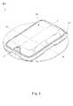
図1を参照し、図1は、本発明の生理信号監視装置1の斜視図である。本発明の生理信号監視装置1は、ベース10、ホルダー20(図示せず)、送信機30及びセンサー40(図示せず)を含む。ベース10は、生体(人体など)の皮膚表面に固定され得る。センサー40はホルダー20に固定されている。ホルダー20は、ベース10と組み合わせることができる。送信機30は、ホルダー20上に取り外し可能に配置されている。 With reference to FIG. 1, FIG. 1 is a perspective view of the physiological
図2Aを参照し、図2Aは、本発明の生理信号監視装置1の分解斜視図である。ベース10、センサー40を運ぶホルダー20、及び送信機30との間の対応位置は、図2Aから見ることができる。ユーザーが生理信号監視装置1を設置するとき、ベース10は最初に皮膚表面に固定され、ホルダー20は、追加の埋め込み装置(図示せず)によってベース10と係合して、センサー40を皮膚の下に埋め込む。埋め込み装置が取り外された後、ホルダー20は、ユーザーの皮膚表面に固定されたベース10と組み合わされる。送信機30は、ベース10上で覆われ、センサー40に電気的に接続されて、センサー40からの生理信号を受信し外部装置に送信する。送信機30がベース10と組み合わされる方向を示すために、送信機30の上面30Aが図2Aに示されている。 With reference to FIG. 2A, FIG. 2A is an exploded perspective view of the physiological
図2Bを参照し、図2Bは、本発明の生理信号監視装置1の別の分解斜視図である。ベース10、ホルダー20と送信機30との間の対応構造をより明確に理解するために、送信機30の下面30Bが図2Bに示されている。送信機30の下面30Bは、第一開放部34及び一対の第二開放部36を備え、第一開放部34は、ホルダー20及びベース10の収容部14を収容するために使用され、第二開放部36は、ベース10の一対の第一係合部材16を収容するために使用される。第二係合部材38は、第一係合部材16に対応するように、各第二開放部36の内側に設けられている。送信機30がベース10と組み合わされると、各第二開放部36の第二係合部材38は、対応する第一係合部材16と係合する。以下、各主要構造の構成要素を順番に説明する。 With reference to FIG. 2B, FIG. 2B is another exploded perspective view of the physiological
ベース10の詳細な説明について、図2Aと図2Bを参照する。ベース10は、パッチ11、貫通孔12、ベース本体13、収容部14、第一フールプルーフ部15、一対の第一係合部材16、二つの位置決めピラー17及び第一弾性体18を含む。パッチ11は、ベース10の底面に配置され、生体の皮膚表面に付着するために使用される。パッチ11には防水材が含まれており、汚れた液体がパッチ11を透過して傷口に接触するのを防ぎ、傷口感染のリスクを回避する。貫通孔12は、生体の皮膚の下にセンサー40の信号検出端44を埋め込むための収容部14を備えている。収容部14は、ホルダー20を収容するために使用される。ベース本体13は、送信機30のエッジの形状に対応する周辺部分を有する。第一フールプルーフ部15は、送信機30がベース10上に配置されたとき、送信機30の第二フールプルーフ部32に対応するように、ベース本体13の周辺部分に配置される。第一フールプルーフ部15及び第二フールプルーフ部32により、ユーザーは、後者の送信機30を前者のベース10に取り付けるときに、送信機30及びベース10の設置方向を容易に識別することができる。一対の第一係合部材16は、ベース本体13の上面に突出して設けられ、各第一係合部材16は、送信機30の底部と係合するための送信機30の第二開放部36に対応する。ホルダー20がベース10に組み合わされると、二つの位置決めピラー17がホルダー20の底部の位置決め孔26に収容され(図7Aと7Bに示されるように)、第一弾性体18は、収容部14の縁部に配置されて、ホルダー20との締まりばめを形成することによって、ホルダー20をベース10に制限及び固定する。 See FIGS. 2A and 2B for a detailed description of the
図2Bに示されるように、各第一係合部材16は、係合部16Aを含む。各係合部16Aは、送信機30の第二開放部36内の第二係合部材38に対応する。係合部16Aが外力によって押し付けられると、各係合部16Aは、それぞれの第二係合部材38から離れるように回転して、第一係合部材16を第二係合部材38から分離する。 As shown in FIG. 2B, each first engaging
第一弾性体18は、ベース10の上面の収容部14に配置され、弾性材料で作られ、二重射出成形によってベース本体13と形成されて、より硬い材料で作られたホルダー20との締まりばめを形成する。一つの実施形態において、第一弾性体18は、収容部14上に円形に配置されて、ホルダー20を収容するための凹状スロットを形成する。好ましくは、第一弾性体18は、収容部14の周壁の内面、外面及び上面に形成される。別の実施形態において、第一弾性体18は、収容部14上に分散して配置され、この固定領域にホルダー20を収容するための固定領域を限定する。好ましくは、第一弾性体18は、収容部14の周壁の内面、外面及び上面に分散して配置される。 The first
図3と図4に示すように、ポート342は、送信機30に配置されるプリント回路基板33を更に含み、センサー40の上部を収容するための凹部332を有することで、送信機30及びホルダー20の組み立て方向に沿った厚さを減少させる。 As shown in FIGS. 3 and 4, the
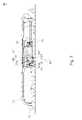
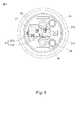
図5A、図5B及び図6を参照し、図5A、図5B及び図6は、それぞれ、本発明の生理信号監視装置1のホルダー20の斜視図、分解斜視図及び断面図である。ホルダー20は、センサー40をその中に収容するための収容凹み22を有する。センサー40は、信号出力端42、信号検出端44、及び信号出力端42と信号検出端44を接続する接続部46とを有するストリップセンサーである。信号出力端42は、収容凹み22上に配置され、送信機30のポート342に電気的に接続し、生理信号を送信機30に出力するように、収容凹み22を超えて部分的に突出している。信号検出端44は、生理信号を検出するように生体の皮下に埋め込まれている。送信機30の対応構造を収容するために、収容凹み22の周囲壁とセンサー40との間に空間S1とS2が存在する。図2Bと図4に示すように、送信機30の下面30Bは、第一開放部34を有し、第一開放部34には、接続スロット344を有するポート342が設けられている。ポート342は、ホルダー20の収容凹み22に突き出ており、収容凹み22に含まれているので、センサー40は、信号出力端42とポート342との間の電気的接続のために、ポート342の接続スロット344に挿入される。ポート342は、収容凹み22の空間S1とS2に相補的に収容される。上記のようなセンサー40の構造とホルダー20の空間構成との連携により、ホルダー20は薄い設計に適合させることができる。 5A, 5B and 6 are referred to, and FIGS. 5A, 5B and 6 are perspective views, exploded perspective views and cross-sectional views of the
ホルダー20は、埋め込み孔24を更に有し、埋め込み孔24は、ベース10上の貫通孔12に対応して、埋め込みチャネルを形成する。埋め込みチャネルは、挿入ツール(図示せず)がそれを通って延びて、信号検出端44を生体の皮膚の下に挿入することに適する。埋め込み孔24は、ホルダー20の上面と下面を貫通し、収容凹み22と連通して、センサー40の一部を収容する。 The
図3、図6、図7A、図7B及び図8を参照し、ホルダー20は、センサー40を固定するための固定凹み27を有し、固定凹み27は、収容凹み22と連通し、埋め込み孔24は、固定凹み27を通じて、収容凹み22と連通する。センサー40は回転角度を有するので、信号出力端42は、収容凹み22に含まれ、信号検出端44は、埋め込み孔24の軸方向に沿って下向きに延在し、したがって、センサー40は、ホルダー20を貫通する。埋め込み孔24及び収容凹み22は、それぞれ二つの異なる縦軸上に構成され(図6の破線の軸線で示されるように)、その結果、センサー40の信号検出端44と信号出力端42は、埋め込み孔24及び収容凹み22の縦軸上に構成されている。 With reference to FIGS. 3, 6, 7A, 7B and 8, the
ホルダー20は、埋め込み孔24を密封し、センサー40を固定するための第二弾性体25を更に有する。第二弾性体25は、防水シール25A、弾性仕切り25B及びブロック要素25Cを含む。防水シール25Aは、埋め込み孔24の上、好ましくは埋め込み孔24の外縁に配置されることにより、送信機30に当接して防水シール構造を形成する。防水シール25Aは、送信機30のポート342の結合部346に対応し(図2Bに示す)、結合部346及び防水シール25Aは、相補的な方法で締まりばめを形成する(図3に示す)。相補的な防水シール構造により、送信機30とベース10との間の空間から外部液体が流れるのを防ぎ、したがって送信機30の電気的特性及びセンサー40の検出感度に影響を与える。上記の防水設計の助けを借りて、ユーザーは、本発明の生理信号監視装置1に対する外部の液体又は汗の影響について心配する必要はない。ユーザーが本発明の生理信号監視装置1を着用した場合でも、入浴やスポーツなどの日常の活動を行うことができる。 The
弾性仕切り25Bは、埋め込み孔24内に配置され、埋め込み孔24と貫通孔12によって限定される埋め込みチャネルの上の空間に対応して、埋め込み孔24を隔て、埋め込み孔24の断面領域全体を覆う。埋め込み装置の挿入ツールが弾性仕切り25Bを通過し、信号検出端44を駆動して皮膚の下に埋め込み、抜取ると、弾性仕切り25Bの設計は、その弾力性により、挿入ツールで穿刺された孔を復元し、しっかりと閉じる。この設計は、埋め込みチャネルを介して逆流する血液が送信機30に向かって漏れて、ユーザーに視覚的な不快感を引き起こすことを回避する。 The
血液が埋め込みチャネルを通って逆流し、送信機30内の電子部品を損傷するのを防ぐために、本発明は、ベース10の貫通孔12に配置されたシール部材12A及びホルダー20の埋め込み孔24に配置された弾性仕切り25Bを提供することにより、貫通孔12及び埋め込み孔24をそれぞれシールする。シール部材12A及び弾性仕切り25Bは、生体の皮膚表面の埋め込み部位から流出する血液が、送信機30内の電子部品を損傷することを避けるために、上記の埋め込みチャネルを通って送信機30に浸透できないように配置される。シール部材12A及び弾性仕切り25Bの材料は、弾性体(ゴムなど)であり得るので、埋め込み針が抜き取れた後に、センサー40の信号検出端44に密に押し付けて装置内部のシール性を維持することができる。更に、ホルダー20の底部が接着剤又は任意形態のシールによってシールされている場合、シール部材12Aも省略できる。他の実施形態において、血液の流出を防ぐために、シール部材12A及び弾性仕切り25Bのうちの1つを選択することができる。 In order to prevent blood from flowing back through the embedding channel and damaging the electronic components in the
ブロック要素25Cは、センサー40の接続部46を保持して、センサー40を固定するように、埋め込み孔24と固定凹み27との間に配置されている。本発明では、防水シール25Aと弾性仕切り25Bの両方の材料はゴムであるが、これに限定されなく、液体の漏れを防ぐ他の弾性材料であってもよい。ブロック要素25Cは、弾性要素又は非弾性要素であり得る。一つの実施形態において、防水シール25A、弾性仕切り25B及びブロック要素25Cが一体的に形成され、埋め込み孔24に埋め込まれている。他の実施形態において、防水シール25A、弾性仕切り25B及びブロック要素25Cは、別々の要素であり得る。 The
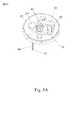
図7A、図7B及び図8を参照し、ホルダー20の底部には、センサー40を制限するために、収容凹み22と固定凹み27との間に配置される複数の制限器29が設けられている。複数の制限器29は、少なくとも一つのフック部29A及び押し部29Bを含み得る。センサー40が固定凹み27からホルダー20に挿入されると、その信号出力端42が収容凹み22を超えて突出するように配置され、信号検出端44を接続する接続部46が固定凹み27に配置され、信号検出端44は、埋め込み孔24を通って延びる。また、制限器29のフック部29Aは、接続部46を制限するために使用され、制限器29の押し部29Bは、接続部46を保持するために使用される。本発明の複数の制限器29は、フック部29A及び押し部29Bの機能に影響を与えることなく、交互にまたは対称的に構成することができる。 With reference to FIGS. 7A, 7B and 8, the bottom of the
センサー40をホルダー20に固定した後、ホルダー20の底部は更に密封される。本発明においてセンサー40を防水及び固定する目的は、ホルダー20の固定凹み27に充填体(すなわち、図7A、図7B、図8と図9に示す点線の領域)を構成することによって達成される。本発明の第一実施形態によれば、ホルダー20の底部は接着剤28で充填される。図9に示すように、収容凹み22に一致する形状の治具50を、ホルダー20の上面から収容凹み22に挿入し、センサー40の信号出力端42をクランプして、接着剤28がオーバーフローしないようにする。接着剤28は、ホルダー20の底面から固定凹み27に充填される。具体的には、接着剤28は、固定凹み27全体に充填され、埋め込み孔24にオーバーフローすることなく、ブロック要素25Cによってブロックされ得る。しかしながら、シールの程度は、必要なシール性能及び他の構成要素の構成に従って変更することができ、本発明は、記載された実施形態に限定されない。接着剤28が固化した後、治具50が取り外される。 After fixing the
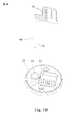
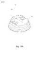
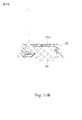
本発明の第二実施形態によれば、ホルダー20は、インサート成形によってワンピースとして作製される。例えば、ホルダー20は、インサート成形中にセンサー40を直接覆い、センサー40をホルダー20内に部分的にカプセル化する。図10Bは、図10Aの破線に沿った断面図を示している。この実施形態では、制限器29とブロック要素25Cは省略され得る。 According to the second embodiment of the present invention, the
図11Aは、第三実施形態に係るホルダーの斜視図であり、図11Bは、図11Aの破線に沿った断面図を示している。本発明の第三実施形態によれば、ホルダー20の底部をシールして、センサー40を保持する効果を達成するために、ホルダー20の底部は、固定凹み27に接着剤ではなくインサータ20Aを充填することによってシールされる。好ましくは、インサータ20Aは底部キャップである。 11A is a perspective view of the holder according to the third embodiment, and FIG. 11B shows a cross-sectional view taken along the broken line of FIG. 11A. According to the third embodiment of the present invention, in order to seal the bottom of the
上記の詳細な説明を通じて、本発明の生理信号監視装置1は、従来技術に対して以下の利点を有することが理解できる。 Through the above detailed description, it can be understood that the physiological
1、薄型化設計
図6に示すように、センサー40の回転形状を一致させるために、ホルダー20の埋め込み孔24及び収容凹み22は、それぞれ二つの異なる縦軸に沿って配置され、互いに連通し、その結果、センサー40は、ホルダー20内に保持することができる。上記のようなセンサー40の構造とホルダー20の空間構成との連携により、本発明で提供されるホルダー20は、薄型化設計に適合させることができる。1. Thin design
As shown in FIG. 6, in order to match the rotational shape of the
送信機30及びホルダー20の組み立て部品に関して、送信機30のポート342は、ホルダー20の収容凹み22の空間S1に収容されている。更に、ホルダー20の上部は、信号出力端42の上部よりも低い。これにより、信号出力端42は、ホルダー20を超えて部分的に突出し、ポート342の接続スロット344及びプリント回路基板33の凹部332に収容されている(図3と図4に示す)。薄型化と脱着性の目的は、上記の相補的な構造設計によって達成される。 Regarding the assembled parts of the
2、防水シール効果
本発明では、ホルダー20の埋め込み孔24に配置された第二弾性体25は、防水シール25Aと弾性仕切り25Bとを含む。防水シール25Aは、外部液体が送信機30とベース10との間の空間に流入し、送信機30の電気的特性及びセンサー40の検出感度に影響を与えることを防ぐように、送信機30に当接して防水シール構造を形成する。弾性仕切り25Bは、埋め込み孔24内に配置され、埋め込み孔24及び貫通孔12によって限定される埋め込みチャネルの上の空間に対応し、埋め込みチャネルを通って逆流する血液が送信機30に向かって漏れることを防ぐ。2. Waterproof seal effect
In the present invention, the second
3、センサーの固定効果
本発明のホルダー20は、固定凹み27及び収容凹み22と固定凹み27との間に配置された制限器29に充填剤を充填することによりセンサー40を搭載するために使用される。また、第二弾性体25のブロック要素25Cは、センサー40を固定するようにセンサー40の接続部46を保持している。従って、本発明は、センサー40が、充填剤、制限器29及びブロック要素25Cの制限及び固定手段を介して、ホルダー20上でより安定して搭載することを可能にする。3. Sensor fixing effect
The
以上、本発明を実施の形態を用いて説明したが、本発明の技術的範囲は上記実施の形態に記載の範囲には限定されない。上記実施の形態に、多様な変更または改良を加え得ることが当業者に明らかである。その様な変更または改良を加えた形態も本発明の技術的範囲に含まれ得ることが、特許請求の範囲の記載から明らかである。
以下に、本願出願の当初の特許請求の範囲に記載された発明を付記する。
[1]
生体の皮膚の下に埋め込んで前記生体からの生体液中の分析物の生理信号を測定するための生理信号監視装置であって、
信号検出端及び信号出力端を有するセンサーであって、前記信号検出端が前記生理信号を検出するために皮膚の下に埋め込まれ、前記信号出力端が前記生理信号を出力する前記センサーと、
前記信号出力端に接続され、前記生理信号を受信するポートを有する送信機と、
前記センサーを搭載するホルダーと、を備え、
前記ホルダーは、
前記センサーの一部を収容し、前記センサーを埋め込むためのチャネルである埋め込み孔と、
前記信号出力端及び前記ポートを収容する収容凹みであって、前記信号出力端が前記ポートに電気的に接続される前記収容凹みと、
前記センサーを固定し、前記収容凹みと連通する固定凹みと、
前記埋め込み孔の上に配置され、前記送信機に当接して防水シール構造を形成する防水シールと、
前記埋め込み孔を隔て、前記埋め込み孔の断面領域全体を覆うように前記埋め込み孔に配置される弾性仕切りと、
前記センサーを保持するように、前記埋め込み孔と前記固定凹みの間に配置されるブロック要素と、を含む、生理信号監視装置。
[2]
前記生理信号監視装置は、ベースを更に含み、
前記ホルダーは、二つの位置決め孔を含み、
前記ベースは、前記二つの位置決め孔に収容される二つの位置決めピラーを含む、[1]に記載の生理信号監視装置。
[3]
前記ホルダーは、前記固定凹みに配置される充填体を更に含む、[1]に記載の生理信号監視装置。
[4]
前記充填体は、接着剤である、[3]に記載の生理信号監視装置。
[5]
前記充填体は、インサータである、[3]に記載の生理信号監視装置。
[6]
前記ホルダーは、前記センサーを制限するための制限器を含む、[1]に記載の生理信号監視装置。
[7]
前記ホルダーは、複数の制限器を含み、
前記複数の制限器は、交互に又は対称的に配置される、[1]に記載の生理信号監視装置。
[8]
前記複数の制限器は、フック部及び押し部を含む、[7]に記載の生理信号監視装置。
[9]
前記ポートは、プリント回路基板を更に含み、
前記プリント回路基板は、凹部を含み、
前記凹部は、前記センサーの上部を収容する、[1]に記載の生理信号監視装置。
[10]
前記ポートは、接続スロットを更に含み、
前記ホルダーの上部が前記信号出力端の上部よりも低く配置されることにより、前記信号出力端が前記ホルダーを超えて突出し、前記接続スロット内に保持される、[1]に記載の生理信号監視装置。
[11]
前記収容凹みは、周囲壁を有し、
前記周囲壁は、前記ポートが前記収容凹みに突出して前記収容凹みに収容されるように、空間によってセンサーから離されている、[1]に記載の生理信号監視装置。
[12]
前記埋め込み孔及び前記収容凹みは、それぞれ、二つの異なる縦軸方向に沿って配置される、[1]に記載の生理信号監視装置。
[13]
前記弾性仕切りは、前記埋め込み孔内の前記センサーの上に配置されている、[1]に記載の生理信号監視装置。
[14]
前記ブロック要素は、弾性要素であることを特徴とする[1]に記載の生理信号監視装置。
[15]
生体液中の分析物の生理信号を測定するためのセンサーを搭載するホルダーであって、
前記センサーは、信号検出端及び信号出力端を有し、
前記ホルダーは、
前記センサーの一部を収容し、前記センサーを埋め込むためのチャネルである埋め込み孔と、
前記信号出力端を収容する収容凹みと、
前記センサーを固定し、前記収容凹みと連通する固定凹みと、
前記埋め込み孔の上に配置される防水シールと、
前記埋め込み孔を隔て、前記埋め込み孔の断面領域全体を覆うように前記埋め込み孔に配置される弾性仕切りと、
前記センサーを保持するように、前記埋め込み孔と前記固定凹みの間に配置されるブロック要素と、を含む、ホルダー。
[16]
前記ホルダーは、前記固定凹みに配置される充填体を更に含む、[15]に記載のホルダー。
[17]
前記充填体は接着剤又はインサータである、[16]に記載のホルダー。
[18]
前記ホルダーは、前記センサーを制限するための複数の制限器を含み、
前記複数の制限器は、交互に又は対称的に配置される、[15]に記載のホルダー。
[19]
前記複数の制限器は、フック部及び押し部を含む、[18]に記載のホルダー。
[20]
前記収容凹みは、周囲壁を有し、
前記周囲壁は、ポートが前記収容凹みに突出して前記収容凹みに収容されるように、空間によってセンサーから離されている、[15]に記載のホルダー。Although the present invention has been described above using the embodiments, the technical scope of the present invention is not limited to the scope described in the above embodiments. It will be apparent to those skilled in the art that various changes or improvements can be made to the above embodiments. It is clear from the description of the claims that the form with such changes or improvements may be included in the technical scope of the present invention.
The inventions described in the original claims of the present application are described below.
[1]
It is a physiological signal monitoring device for measuring a physiological signal of an analytical substance in a biological fluid from the living body by implanting it under the skin of the living body.
A sensor having a signal detection end and a signal output end, wherein the signal detection end is embedded under the skin to detect the physiological signal, and the signal output end outputs the physiological signal.
A transmitter connected to the signal output end and having a port for receiving the physiological signal.
With a holder on which the sensor is mounted,
The holder is
An embedding hole, which is a channel for accommodating a part of the sensor and embedding the sensor,
A housing recess for accommodating the signal output end and the port, wherein the signal output end is electrically connected to the port.
A fixed dent that fixes the sensor and communicates with the housing dent,
A waterproof seal that is placed on the embedded hole and abuts on the transmitter to form a waterproof seal structure.
An elastic partition arranged in the embedding hole so as to cover the entire cross-sectional area of the embedding hole across the embedding hole.
A physiological signal monitoring device comprising a block element disposed between the embedding hole and the fixing recess to hold the sensor.
[2]
The physiological signal monitoring device further includes a base, and the physiological signal monitoring device includes a base.
The holder contains two positioning holes.
The physiological signal monitoring device according to [1], wherein the base includes two positioning pillars housed in the two positioning holes.
[3]
The physiological signal monitoring device according to [1], wherein the holder further includes a filler arranged in the fixed recess.
[4]
The physiological signal monitoring device according to [3], wherein the filler is an adhesive.
[5]
The physiological signal monitoring device according to [3], wherein the filler is an inserter.
[6]
The physiological signal monitoring device according to [1], wherein the holder includes a limiter for limiting the sensor.
[7]
The holder contains a plurality of limiters.
The physiological signal monitoring device according to [1], wherein the plurality of limiters are arranged alternately or symmetrically.
[8]
The physiological signal monitoring device according to [7], wherein the plurality of limiters include a hook portion and a push portion.
[9]
The port further comprises a printed circuit board.
The printed circuit board includes recesses and contains recesses.
The physiological signal monitoring device according to [1], wherein the concave portion accommodates the upper portion of the sensor.
[10]
The port further includes a connection slot.
The physiological signal monitoring according to [1], wherein the upper part of the holder is arranged lower than the upper part of the signal output end, so that the signal output end protrudes beyond the holder and is held in the connection slot. Device.
[11]
The containment recess has a peripheral wall and
The physiological signal monitoring device according to [1], wherein the peripheral wall is separated from the sensor by a space so that the port protrudes into the accommodation recess and is accommodated in the accommodation recess.
[12]
The physiological signal monitoring device according to [1], wherein the embedded hole and the accommodating recess are arranged along two different vertical axis directions, respectively.
[13]
The physiological signal monitoring device according to [1], wherein the elastic partition is arranged on the sensor in the embedded hole.
[14]
The physiological signal monitoring device according to [1], wherein the block element is an elastic element.
[15]
A holder equipped with a sensor for measuring the physiological signal of the analyzed product in the biological fluid.
The sensor has a signal detection end and a signal output end.
The holder is
An embedding hole, which is a channel for accommodating a part of the sensor and embedding the sensor,
A housing recess for accommodating the signal output end and
A fixed dent that fixes the sensor and communicates with the housing dent,
A waterproof seal placed on the embedding hole and
An elastic partition arranged in the embedding hole so as to cover the entire cross-sectional area of the embedding hole across the embedding hole.
A holder comprising a block element disposed between the embedding hole and the fixing recess to hold the sensor.
[16]
The holder according to [15], wherein the holder further includes a filler arranged in the fixed recess.
[17]
The holder according to [16], wherein the filler is an adhesive or an inserter.
[18]
The holder comprises a plurality of limiters for limiting the sensor.
The holder according to [15], wherein the plurality of limiters are arranged alternately or symmetrically.
[19]
The holder according to [18], wherein the plurality of limiters include a hook portion and a push portion.
[20]
The containment recess has a peripheral wall and
The holder according to [15], wherein the peripheral wall is separated from the sensor by a space so that the port protrudes into the accommodation recess and is accommodated in the accommodation recess.
Claims (13)
Translated fromJapanese信号検出端及び信号出力端を有するセンサーであって、前記信号検出端が前記生理信号を検出するために皮膚の下に埋め込まれ、前記信号出力端が前記生理信号を出力する前記センサーと、
前記信号出力端に接続され、前記生理信号を受信するポートを有する送信機と、
前記センサーを搭載するホルダーと、を備え、
前記ホルダーは、
前記センサーの一部を収容し、前記センサーを埋め込むためのチャネルである埋め込み孔と、
前記信号出力端及び前記ポートを収容する収容凹みであって、前記信号出力端が前記ポートに電気的に接続される前記収容凹みと、
前記センサーを固定し、前記収容凹みと連通する固定凹みと、
前記埋め込み孔の上に配置され、前記送信機に当接して防水シール構造を形成する防水シールと、
前記埋め込み孔を隔て、前記埋め込み孔の断面領域全体を覆うように前記埋め込み孔に配置される弾性仕切りと、
前記センサーを保持するように、前記埋め込み孔と前記固定凹みの間に配置されるブロック要素と、を含み、
前記防水シール、前記弾性仕切り及び前記ブロック要素は、一体的に形成され、前記埋め込み孔に埋め込まれている、生理信号監視装置。It is a physiological signal monitoring device for measuring a physiological signal of an analytical substance in a biological fluid from the living body by implanting it under the skin of the living body.
A sensor having a signal detection end and a signal output end, wherein the signal detection end is embedded under the skin to detect the physiological signal, and the signal output end outputs the physiological signal.
A transmitter connected to the signal output end and having a port for receiving the physiological signal.
With a holder on which the sensor is mounted,
The holder is
An embedding hole, which is a channel for accommodating a part of the sensor and embedding the sensor,
A housing recess for accommodating the signal output end and the port, wherein the signal output end is electrically connected to the port.
A fixed dent that fixes the sensor and communicates with the housing dent,
A waterproof seal that is placed on the embedded hole and abuts on the transmitter to form a waterproof seal structure.
An elastic partition arranged in the embedding hole so as to cover the entire cross-sectional area of the embedding hole across the embedding hole.
Includes a block element disposed between the embedding hole and the fixation recess to hold the sensor.
A physiological signal monitoring devicein which the waterproof seal, the elastic partition, and the block element are integrally formed and embedded in the embedded hole .
前記ホルダーは、二つの位置決め孔を含み、
前記ベースは、前記二つの位置決め孔に収容される二つの位置決めピラーを含む、請求項1に記載の生理信号監視装置。The physiological signal monitoring device further includes a base, and the physiological signal monitoring device includes a base.
The holder contains two positioning holes.
The physiological signal monitoring device according to claim 1, wherein the base includes two positioning pillars housed in the two positioning holes.
前記充填体は、接着剤又はインサータである、請求項1に記載の生理信号監視装置。The holder further comprises a filler placed in the fixed recess.
The physiological signal monitoring device according to claim 1, wherein the filler is an adhesive or an inserter.
前記複数の制限器は、交互に又は対称的に配置され、
前記複数の制限器は、フック部及び押し部を含む、請求項1に記載の生理信号監視装置。The holder contains a plurality of limiters.
The plurality of limiters are arranged alternately or symmetrically.
The physiological signal monitoring device according to claim 1, wherein the plurality of limiters include a hook portion and a push portion.
前記プリント回路基板は、凹部を含み、
前記凹部は、前記センサーの上部を収容する、請求項1に記載の生理信号監視装置。The port further comprises a printed circuit board.
The printed circuit board includes recesses and contains recesses.
The physiological signal monitoring device according to claim 1, wherein the recess accommodates an upper portion of the sensor.
前記ホルダーの上部が前記信号出力端の上部よりも低く配置されることにより、前記信号出力端が前記ホルダーを超えて突出し、前記接続スロット内に保持される、請求項1に記載の生理信号監視装置。The port further includes a connection slot.
The physiological signal monitoring according to claim 1, wherein the upper portion of the holder is arranged lower than the upper portion of the signal output end, so that the signal output end protrudes beyond the holder and is held in the connection slot. Device.
前記周囲壁は、前記センサーとの間に空間が存在し、
前記ポートは、前記収容凹みに収容される、請求項1に記載の生理信号監視装置。The containment recess has a peripheral wall and
The surrounding wall has aspace between it and the sensor.
The physiological signal monitoring device according to claim 1, wherein the port is housed in the housing recess.
前記弾性仕切りは、前記埋め込み孔内の前記センサーの上に配置されており、
前記ブロック要素は、弾性要素であることを特徴とする請求項1に記載の生理信号監視装置。The embedding hole and the accommodating recess are respectively arranged along two different vertical directions.
The elastic partition is located on the sensor in the embedding hole.
The physiological signal monitoring device according to claim 1, wherein the block element is an elastic element.
前記センサーは、信号検出端及び信号出力端を有し、
前記ホルダーは、
前記センサーの一部を収容し、前記センサーを埋め込むためのチャネルである埋め込み孔と、
前記信号出力端を収容する収容凹みと、
前記センサーを固定し、前記収容凹みと連通する固定凹みと、
前記埋め込み孔の上に配置される防水シールと、
前記埋め込み孔を隔て、前記埋め込み孔の断面領域全体を覆うように前記埋め込み孔に配置される弾性仕切りと、
前記センサーを保持するように、前記埋め込み孔と前記固定凹みの間に配置されるブロック要素と、を含み、
前記防水シール、前記弾性仕切り及び前記ブロック要素は、一体的に形成され、前記埋め込み孔に埋め込まれている、ホルダー。A holder equipped with a sensor for measuring the physiological signal of the analyzed product in the biological fluid.
The sensor has a signal detection end and a signal output end.
The holder is
An embedding hole, which is a channel for accommodating a part of the sensor and embedding the sensor,
A housing recess for accommodating the signal output end and
A fixed dent that fixes the sensor and communicates with the housing dent,
A waterproof seal placed on the embedding hole and
An elastic partition arranged in the embedding hole so as to cover the entire cross-sectional area of the embedding hole across the embedding hole.
Includes a block element disposed between the embedding hole and the fixation recess to hold the sensor.
A holderin which the waterproof seal, the elastic partition and the block element are integrally formed and embedded in the embedding hole .
前記充填体は接着剤又はインサータである、請求項10に記載のホルダー。The holder further comprises a filler placed in the fixed recess.
The holder according to claim 10, wherein the filler is an adhesive or an inserter.
前記複数の制限器は、フック部及び押し部を含む、請求項10に記載のホルダー。The holder comprises a plurality of limiters for limiting the sensor, the plurality of limiters being arranged alternately or symmetrically.
The holder according to claim 10, wherein the plurality of limiters include a hook portion and a push portion.
前記周囲壁は、前記センサーとの間に空間が存在し、
ポートは、前記収容凹みに収容される、請求項10に記載のホルダー。The containment recess has a peripheral wall and
The surrounding wall has aspace between it and the sensor.
The holder according to claim 10, wherein the port is housed in the housing recess.
Applications Claiming Priority (2)
| Application Number | Priority Date | Filing Date | Title |
|---|---|---|---|
| US201962882140P | 2019-08-02 | 2019-08-02 | |
| US62/882,140 | 2019-08-02 |
Publications (2)
| Publication Number | Publication Date |
|---|---|
| JP2021041146A JP2021041146A (en) | 2021-03-18 |
| JP7077370B2true JP7077370B2 (en) | 2022-05-30 |
Family
ID=71899622
Family Applications (3)
| Application Number | Title | Priority Date | Filing Date |
|---|---|---|---|
| JP2020131738AActiveJP6986603B2 (en) | 2019-08-02 | 2020-08-03 | Insertion module and insertion device with it |
| JP2020131795AActiveJP7134201B2 (en) | 2019-08-02 | 2020-08-03 | physiological signal monitoring device |
| JP2020131916AActiveJP7077370B2 (en) | 2019-08-02 | 2020-08-03 | Physiological signal monitoring device and its sensor holder |
Family Applications Before (2)
| Application Number | Title | Priority Date | Filing Date |
|---|---|---|---|
| JP2020131738AActiveJP6986603B2 (en) | 2019-08-02 | 2020-08-03 | Insertion module and insertion device with it |
| JP2020131795AActiveJP7134201B2 (en) | 2019-08-02 | 2020-08-03 | physiological signal monitoring device |
Country Status (10)
| Country | Link |
|---|---|
| US (7) | US11504032B2 (en) |
| EP (7) | EP3771409B1 (en) |
| JP (3) | JP6986603B2 (en) |
| KR (2) | KR102449247B1 (en) |
| CN (22) | CN112294301B (en) |
| AU (2) | AU2020294300B2 (en) |
| CA (2) | CA3104329A1 (en) |
| DE (1) | DE202020104460U1 (en) |
| TW (26) | TWI723733B (en) |
| WO (2) | WO2021023148A1 (en) |
Families Citing this family (37)
| Publication number | Priority date | Publication date | Assignee | Title |
|---|---|---|---|---|
| US9788771B2 (en) | 2006-10-23 | 2017-10-17 | Abbott Diabetes Care Inc. | Variable speed sensor insertion devices and methods of use |
| US11071478B2 (en) | 2017-01-23 | 2021-07-27 | Abbott Diabetes Care Inc. | Systems, devices and methods for analyte sensor insertion |
| CN112423664B (en) | 2018-06-07 | 2025-01-21 | 雅培糖尿病护理公司 | Focused sterilization and sterilized sub-assemblies for analyte monitoring systems |
| CA3230184A1 (en)* | 2019-08-02 | 2021-02-02 | Bionime Corporation | Physiological signal monitoring device |
| CN112294301B (en)* | 2019-08-02 | 2024-12-31 | 华广生技股份有限公司 | Physiological signal sensor device |
| EP4017357A4 (en)* | 2019-08-19 | 2023-04-19 | Medtrum Technologies Inc. | MEASURING DEVICE |
| CA3188510A1 (en) | 2020-08-31 | 2022-03-03 | Vivek S. RAO | Systems, devices, and methods for analyte sensor insertion |
| AU2021344214A1 (en)* | 2020-09-15 | 2023-03-23 | Abbott Diabetes Care Inc. | Systems, devices, and methods for analyte monitoring |
| US11852643B2 (en)* | 2020-10-13 | 2023-12-26 | Bionime Corporation | Physiological signal monitoring device |
| TWI793800B (en)* | 2020-10-14 | 2023-02-21 | 華廣生技股份有限公司 | Insertion needle structure and inserter |
| TWI849296B (en)* | 2021-01-08 | 2024-07-21 | 華廣生技股份有限公司 | Patch and method for using a patch |
| EP4346587A4 (en)* | 2021-05-31 | 2024-10-30 | Medtrum Technologies Inc. | ANALYTE DETECTION DEVICE INTEGRATED INTO A BATTERY ENCLOSURE |
| CN113499127B (en)* | 2021-06-28 | 2024-03-01 | 苏州百孝医疗科技有限公司 | Fixing structure of sensor base and method for removing sensor base |
| KR102592776B1 (en)* | 2021-06-29 | 2023-10-25 | 주식회사 아이센스 | Needle for transcutaneous sensor insertion and needle assembly having the same |
| CN115704820B (en)* | 2021-08-06 | 2025-08-05 | 上海移宇科技股份有限公司 | Body fluid analyte detection devices |
| CN115868974B (en)* | 2021-09-29 | 2025-09-09 | 上海微创生命科技有限公司 | Medical equipment and medical auxiliary device |
| CN116172549B (en)* | 2021-11-26 | 2025-08-12 | 上海微创生命科技有限公司 | medical devices |
| CN116195994A (en)* | 2021-11-30 | 2023-06-02 | 上海微创生命科技有限公司 | Sterilization box assembly, implanter and implantation system |
| CN114642426A (en)* | 2022-03-02 | 2022-06-21 | 苏州百孝医疗科技有限公司 | Method for manufacturing electronic device and electronic device |
| CN114831633B (en)* | 2022-04-29 | 2025-07-25 | 天津九安医疗电子股份有限公司 | Sensor implantation device |
| CN115089274A (en)* | 2022-05-26 | 2022-09-23 | 浙江康德莱医疗器械股份有限公司 | A puncture guide needle |
| WO2024028507A1 (en)* | 2022-08-05 | 2024-02-08 | Unomedical A/S | Inserter assembly and method |
| WO2024028506A1 (en)* | 2022-08-05 | 2024-02-08 | Unomedical A/S | Anchor assembly |
| TWD226583S (en)* | 2022-08-31 | 2023-07-21 | 華廣生技股份有限公司 | Physiological signal monitoring patch |
| TWD226584S (en)* | 2022-08-31 | 2023-07-21 | 華廣生技股份有限公司 | Physiological signal monitoring patch |
| TWD226582S (en)* | 2022-08-31 | 2023-07-21 | 華廣生技股份有限公司 | Physiological signal monitoring patch |
| TWI806771B (en)* | 2022-09-16 | 2023-06-21 | 英業達股份有限公司 | Anti-static electricity type electronic device |
| CN116058937A (en)* | 2022-10-11 | 2023-05-05 | 深圳可孚生物科技有限公司 | A biosensor-assisted implantation device |
| WO2024080457A1 (en)* | 2022-10-14 | 2024-04-18 | 국민대학교산학협력단 | Scalable implantable biosensor device |
| CN115399757B (en)* | 2022-10-31 | 2023-01-24 | 深圳刷新生物传感科技有限公司 | High-reliability implantation device of implantable biosensor |
| USD1095842S1 (en)* | 2023-02-10 | 2025-09-30 | I-Sens, Inc. | Continuous blood glucose measurement sensor |
| US20240298929A1 (en)* | 2023-03-08 | 2024-09-12 | Medtronic Minimed, Inc. | Substrate sealing configurations and methods |
| TWD231831S (en)* | 2023-03-15 | 2024-06-21 | 華廣生技股份有限公司 臺中市南區大慶街2段100號 (中華民國) | Part of a splitter for a physiological monitoring device |
| CN116626132A (en)* | 2023-05-15 | 2023-08-22 | 广州达安基因股份有限公司 | Implantable biosensor and preparation method thereof |
| CN116548963B (en)* | 2023-07-07 | 2023-09-05 | 苏州百孝医疗科技有限公司 | Percutaneous analyte continuous detection system and method of installing same |
| EP4534008A1 (en)* | 2023-08-21 | 2025-04-09 | Shanghai United Imaging Microelectronics Technology Co., Ltd. | Analyte sensor |
| WO2025162779A1 (en)* | 2024-01-31 | 2025-08-07 | Roche Diabetes Care Gmbh | Continuous analyte monitoring device |
Citations (4)
| Publication number | Priority date | Publication date | Assignee | Title |
|---|---|---|---|---|
| JP2015509011A (en) | 2011-12-11 | 2015-03-26 | アボット ダイアベティス ケア インコーポレイテッドAbbott Diabetes Care Inc. | Specimen sensor device, connection unit and method |
| JP2017525516A (en) | 2014-09-03 | 2017-09-07 | ノヴァ バイオメディカル コーポレイション | Subcutaneous sensor inserter and method |
| WO2017187943A1 (en) | 2016-04-27 | 2017-11-02 | パナソニックヘルスケアホールディングス株式会社 | Sensor insertion device and biosensor |
| JP2019507613A (en) | 2015-12-30 | 2019-03-22 | デックスコム・インコーポレーテッド | Transdermal analyte sensor system and method |
Family Cites Families (252)
| Publication number | Priority date | Publication date | Assignee | Title |
|---|---|---|---|---|
| US3102539A (en)* | 1960-11-23 | 1963-09-03 | Graham Chemical Corp | Disposable cartridge type hypodermic syringe devices |
| EP0221005A3 (en)* | 1985-09-07 | 1987-12-02 | Wagner, Wolfgang, Dr.med. | Injection device with sensor |
| US5165407A (en)* | 1990-04-19 | 1992-11-24 | The University Of Kansas | Implantable glucose sensor |
| US5299571A (en)* | 1993-01-22 | 1994-04-05 | Eli Lilly And Company | Apparatus and method for implantation of sensors |
| JP2947064B2 (en)* | 1994-05-18 | 1999-09-13 | 住友電装株式会社 | connector |
| CN1174713C (en)* | 1995-08-29 | 2004-11-10 | 光谱股份有限公司 | Microporation method of human skin for drug delivery and monitoring applications |
| US6013058A (en)* | 1996-06-12 | 2000-01-11 | Biolink Corporation | Device for subcutaneous accessibility |
| US7899511B2 (en)* | 2004-07-13 | 2011-03-01 | Dexcom, Inc. | Low oxygen in vivo analyte sensor |
| US7657297B2 (en)* | 2004-05-03 | 2010-02-02 | Dexcom, Inc. | Implantable analyte sensor |
| JPH10253654A (en)* | 1997-03-11 | 1998-09-25 | Fujitsu Ten Ltd | Acceleration sensor packaging structure |
| KR20010013962A (en)* | 1997-06-20 | 2001-02-26 | 에프.지.엠. 헤르만스 ; 이.에이치. 리링크 | Preloaded implantation device |
| US6516808B2 (en)* | 1997-09-12 | 2003-02-11 | Alfred E. Mann Foundation For Scientific Research | Hermetic feedthrough for an implantable device |
| US5967986A (en)* | 1997-11-25 | 1999-10-19 | Vascusense, Inc. | Endoluminal implant with fluid flow sensing capability |
| US8465425B2 (en)* | 1998-04-30 | 2013-06-18 | Abbott Diabetes Care Inc. | Analyte monitoring device and methods of use |
| US8346337B2 (en)* | 1998-04-30 | 2013-01-01 | Abbott Diabetes Care Inc. | Analyte monitoring device and methods of use |
| GB2337118A (en)* | 1998-05-06 | 1999-11-10 | Csi Technology Inc | Interchangeable sensor monitoring device |
| AU1889001A (en)* | 1999-12-13 | 2001-06-18 | Arkray, Inc. | Body fluid measuring apparatus with lancet and lancet holder used for the measuring apparatus |
| US7393344B2 (en)* | 1999-12-23 | 2008-07-01 | Owais Mohammed | Hypodermic syringe needle assembly and method of making the same |
| DE60015721T2 (en)* | 2000-03-21 | 2005-03-31 | Radi Medical Systems Ab | Passive biotelemetry |
| JP4700209B2 (en)* | 2000-03-21 | 2011-06-15 | ラディ・メディカル・システムズ・アクチェボラーグ | Passive biotelemetry |
| US7006858B2 (en)* | 2000-05-15 | 2006-02-28 | Silver James H | Implantable, retrievable sensors and immunosensors |
| US7181261B2 (en)* | 2000-05-15 | 2007-02-20 | Silver James H | Implantable, retrievable, thrombus minimizing sensors |
| US6589229B1 (en)* | 2000-07-31 | 2003-07-08 | Becton, Dickinson And Company | Wearable, self-contained drug infusion device |
| US8454552B2 (en)* | 2000-08-24 | 2013-06-04 | Cardiac Science Corporation | Method for constructing an instrument with a covered bore for subcutaneous implantation |
| US8348882B2 (en)* | 2000-08-24 | 2013-01-08 | Cardiac Science Corporation | Instrument with a covered bore for subcutaneous implantation |
| US7736330B2 (en)* | 2000-08-24 | 2010-06-15 | Bardy Gust H | Subcutaneous implantation instrument with dissecting tool and method of construction |
| GB0025147D0 (en)* | 2000-10-13 | 2000-11-29 | Torsana Diabetes Diagnostics A | Optical sensor for in situ measurement of analytes |
| US6560471B1 (en)* | 2001-01-02 | 2003-05-06 | Therasense, Inc. | Analyte monitoring device and methods of use |
| EP1381408A4 (en) | 2001-02-22 | 2007-06-13 | Insulet Corp | Modular infusion device and method |
| WO2003088851A1 (en)* | 2001-06-12 | 2003-10-30 | Pelikan Technologies, Inc. | Tissue penetration device |
| GB0116853D0 (en)* | 2001-07-10 | 2001-09-05 | Torsana Diabetes Diagnostics A | Optical sensor containing particles for in SITU measurement of analytes |
| US7025760B2 (en)* | 2001-09-07 | 2006-04-11 | Medtronic Minimed, Inc. | Method and system for non-vascular sensor implantation |
| US8506550B2 (en)* | 2001-09-07 | 2013-08-13 | Medtronic Minimed, Inc. | Method and system for non-vascular sensor implantation |
| WO2003034902A2 (en)* | 2001-10-23 | 2003-05-01 | Medtronic Minimed Inc. | Method and system for non-vascular sensor implantation |
| US9492111B2 (en)* | 2002-04-22 | 2016-11-15 | Medtronic Minimed, Inc. | Methods and materials for stabilizing analyte sensors |
| US7020508B2 (en)* | 2002-08-22 | 2006-03-28 | Bodymedia, Inc. | Apparatus for detecting human physiological and contextual information |
| US7070591B2 (en)* | 2002-09-17 | 2006-07-04 | Transoma Medical, Inc. | Vascular access port with physiological sensor |
| US7736309B2 (en)* | 2002-09-27 | 2010-06-15 | Medtronic Minimed, Inc. | Implantable sensor method and system |
| US7381184B2 (en)* | 2002-11-05 | 2008-06-03 | Abbott Diabetes Care Inc. | Sensor inserter assembly |
| CN2585624Y (en)* | 2002-12-03 | 2003-11-12 | 名世电子企业股份有限公司 | pulse meter transmitter |
| US20070208245A1 (en)* | 2003-08-01 | 2007-09-06 | Brauker James H | Transcutaneous analyte sensor |
| US7519408B2 (en)* | 2003-11-19 | 2009-04-14 | Dexcom, Inc. | Integrated receiver for continuous analyte sensor |
| US7699807B2 (en)* | 2003-11-10 | 2010-04-20 | Smiths Medical Asd, Inc. | Device and method for insertion of a cannula of an infusion device |
| US7309326B2 (en)* | 2003-11-18 | 2007-12-18 | Icu Medical, Inc. | Infusion set |
| WO2005092177A1 (en)* | 2004-03-22 | 2005-10-06 | Bodymedia, Inc. | Non-invasive temperature monitoring device |
| US20070135697A1 (en)* | 2004-04-19 | 2007-06-14 | Therasense, Inc. | Method and apparatus for providing sensor guard for data monitoring and detection systems |
| US8792955B2 (en)* | 2004-05-03 | 2014-07-29 | Dexcom, Inc. | Transcutaneous analyte sensor |
| US8452368B2 (en)* | 2004-07-13 | 2013-05-28 | Dexcom, Inc. | Transcutaneous analyte sensor |
| JP4870075B2 (en)* | 2004-07-13 | 2012-02-08 | デックスコム・インコーポレーテッド | Transcutaneous analyte sensor |
| US8565848B2 (en)* | 2004-07-13 | 2013-10-22 | Dexcom, Inc. | Transcutaneous analyte sensor |
| US7783333B2 (en)* | 2004-07-13 | 2010-08-24 | Dexcom, Inc. | Transcutaneous medical device with variable stiffness |
| US7654956B2 (en)* | 2004-07-13 | 2010-02-02 | Dexcom, Inc. | Transcutaneous analyte sensor |
| TWM269870U (en)* | 2004-10-01 | 2005-07-11 | Taiject Medical Device Co Ltd | Easy assembling and operating blood collector |
| US9788771B2 (en)* | 2006-10-23 | 2017-10-17 | Abbott Diabetes Care Inc. | Variable speed sensor insertion devices and methods of use |
| CN101107025A (en)* | 2005-01-17 | 2008-01-16 | 诺和诺德公司 | Fluid delivery device with integrated monitoring of physiological characteristics |
| US7285846B1 (en)* | 2005-02-22 | 2007-10-23 | Littelfuse, Inc. | Integrated circuit package with ESD protection |
| JP2006334155A (en)* | 2005-06-02 | 2006-12-14 | Terumo Corp | Blood component measuring apparatus and chip for measuring blood component |
| WO2007003431A1 (en)* | 2005-07-06 | 2007-01-11 | Medizinische Universität Graz | Device for and method of delivery and removal of substances in and from a tissue or vessel |
| US9072476B2 (en)* | 2005-09-23 | 2015-07-07 | Medtronic Minimed, Inc. | Flexible sensor apparatus |
| US8123705B2 (en)* | 2005-10-06 | 2012-02-28 | Boston Scientific Scimed, Inc. | Adjustable profile probe |
| US20070173706A1 (en)* | 2005-11-11 | 2007-07-26 | Isense Corporation | Method and apparatus for insertion of a sensor |
| US9615851B2 (en)* | 2005-11-11 | 2017-04-11 | Waveform Technologies, Inc. | Method and apparatus for insertion of a sensor |
| US9757061B2 (en)* | 2006-01-17 | 2017-09-12 | Dexcom, Inc. | Low oxygen in vivo analyte sensor |
| JP4802737B2 (en)* | 2006-01-31 | 2011-10-26 | パナソニック株式会社 | Chemical solution administration device and control method thereof |
| EP3165247B1 (en)* | 2006-02-09 | 2020-10-28 | DEKA Products Limited Partnership | Pumping fluid delivery systems and methods using force application assembley |
| ES2871822T3 (en)* | 2006-02-22 | 2021-11-02 | Dexcom Inc | Analyte sensor |
| US20090131778A1 (en)* | 2006-03-28 | 2009-05-21 | Jina Arvind N | Devices, systems, methods and tools for continuous glucose monitoring |
| US20090012372A1 (en)* | 2006-06-12 | 2009-01-08 | Novalert, Inc. | External sensing for implant rupture |
| US8583224B2 (en)* | 2006-09-08 | 2013-11-12 | Cardiac Pacemakers, Inc. | Implantable medical device and methods for automated detection of infection |
| EP2079358B1 (en)* | 2006-09-27 | 2011-08-10 | University of Connecticut | Implantable biosensor and methods of use thereof |
| US20080091089A1 (en)* | 2006-10-12 | 2008-04-17 | Kenneth Shane Guillory | Single use, self-contained surface physiological monitor |
| US8214007B2 (en)* | 2006-11-01 | 2012-07-03 | Welch Allyn, Inc. | Body worn physiological sensor device having a disposable electrode module |
| TWM314590U (en)* | 2006-12-11 | 2007-07-01 | Health & Life Co Ltd | Physical detector having water-proof structure |
| WO2008105768A1 (en)* | 2007-03-01 | 2008-09-04 | Dexcom, Inc. | Analyte sensor |
| EP1972267A1 (en)* | 2007-03-20 | 2008-09-24 | Roche Diagnostics GmbH | System for in vivo measurement of an analyte concentration |
| JP5429586B2 (en)* | 2007-03-30 | 2014-02-26 | 株式会社タニタ | Blood glucose state estimation method and apparatus |
| CA2680841A1 (en)* | 2007-04-04 | 2008-10-16 | Isense Corporation | Analyte sensing device having one or more sensing electrodes |
| US20130144144A1 (en)* | 2007-04-19 | 2013-06-06 | C.G.M.3 Ltd. | Device system and method for monitoring and controlling blood analyte levels |
| JP5546243B2 (en)* | 2007-07-18 | 2014-07-09 | パナソニックヘルスケア株式会社 | Blood test equipment |
| JP2009028062A (en)* | 2007-07-24 | 2009-02-12 | Sumitomo Electric Ind Ltd | Blood collector for biosensor and sensor chip measuring device |
| US20090043183A1 (en)* | 2007-08-08 | 2009-02-12 | Lifescan, Inc. | Integrated stent and blood analyte monitoring system |
| GB0716427D0 (en)* | 2007-08-23 | 2007-10-03 | Smartsensor Telemed Ltd | Glucose tolerance test device |
| US20090105634A1 (en)* | 2007-10-17 | 2009-04-23 | Alza Corporation | Anodic Reservoir for Electrotransport of Cationic Drug |
| AU2009219678A1 (en)* | 2008-02-27 | 2009-09-03 | Mon4D Ltd. | Device, system and method for modular analyte monitoring |
| ITTO20080143A1 (en)* | 2008-02-28 | 2009-08-29 | Amc Instruments S R L | DEVICE FOR MONITORING MULTIFUNE SYSTEMS |
| US9295786B2 (en)* | 2008-05-28 | 2016-03-29 | Medtronic Minimed, Inc. | Needle protective device for subcutaneous sensors |
| TWI354548B (en)* | 2008-07-18 | 2011-12-21 | Bionime Corp | Adjustable assembly of lancet device |
| ES2530450T3 (en)* | 2008-10-02 | 2015-03-03 | Eyesense Ag | Implantable sensor element |
| TWI503101B (en)* | 2008-12-15 | 2015-10-11 | Proteus Digital Health Inc | Body-associated receiver and method |
| US9402544B2 (en)* | 2009-02-03 | 2016-08-02 | Abbott Diabetes Care Inc. | Analyte sensor and apparatus for insertion of the sensor |
| US20100256524A1 (en)* | 2009-03-02 | 2010-10-07 | Seventh Sense Biosystems, Inc. | Techniques and devices associated with blood sampling |
| TWI413770B (en)* | 2009-04-24 | 2013-11-01 | Univ Nat Taiwan | Wireless biomedical monitoring system |
| EP2266458A1 (en)* | 2009-06-23 | 2010-12-29 | Roche Diagnostics GmbH | Sensor for in-vivo measurements |
| US8996089B2 (en)* | 2009-06-30 | 2015-03-31 | Arkray, Inc. | Continuous analysis device and sample component control system |
| DK3689237T3 (en)* | 2009-07-23 | 2021-08-16 | Abbott Diabetes Care Inc | Method of preparation and system for continuous analyte measurement |
| KR20120047896A (en)* | 2009-08-07 | 2012-05-14 | 우노메디컬 에이/에스 | Delivery device with sensor and one or more cannulas |
| TWI481383B (en)* | 2009-09-25 | 2015-04-21 | Univ Nat Chiao Tung | Biosensor and electrode structure thereof |
| EP2482724A2 (en) | 2009-09-30 | 2012-08-08 | Dexcom, Inc. | Transcutaneous analyte sensor |
| WO2011053788A2 (en)* | 2009-10-30 | 2011-05-05 | Seventh Sense Biosystems, Inc. | Relatively small devices applied to the skin, modular systems, and methods of use thereof |
| US10918298B2 (en)* | 2009-12-16 | 2021-02-16 | The Board Of Trustees Of The University Of Illinois | High-speed, high-resolution electrophysiology in-vivo using conformal electronics |
| EP2335565A1 (en)* | 2009-12-18 | 2011-06-22 | Roche Diagnostics GmbH | Protective container for holding reusable diagnostic components |
| WO2011088211A2 (en)* | 2010-01-13 | 2011-07-21 | Seventh Sense Biosystems, Inc. | Sampling device interfaces |
| WO2011112931A1 (en)* | 2010-03-12 | 2011-09-15 | The Board Of Trustees Of The University Of Illinois | Waterproof stretchable optoelectronics |
| US10448872B2 (en)* | 2010-03-16 | 2019-10-22 | Medtronic Minimed, Inc. | Analyte sensor apparatuses having improved electrode configurations and methods for making and using them |
| AU2011230596A1 (en)* | 2010-03-24 | 2012-01-19 | Abbott Diabetes Care Inc. | Medical device inserters and processes of inserting and using medical devices |
| LT3622883T (en)* | 2010-03-24 | 2021-08-25 | Abbott Diabetes Care, Inc. | Medical device inserters and processes of inserting and using medical devices |
| JP2011204483A (en)* | 2010-03-25 | 2011-10-13 | Denso Corp | Electrical connector and circuit board mounted with the same |
| KR20130018783A (en)* | 2010-03-30 | 2013-02-25 | 우노메디컬 에이/에스 | Medical device |
| JP2012026910A (en)* | 2010-07-26 | 2012-02-09 | Arkray Inc | Biosensor unit and biosensor system |
| TWI439689B (en)* | 2010-09-23 | 2014-06-01 | Bionime Corp | Electrochemical test specimen |
| DK2621339T3 (en)* | 2010-09-29 | 2020-02-24 | Dexcom Inc | ADVANCED SYSTEM FOR CONTINUOUS ANALYTICAL MONITORING |
| WO2012068393A1 (en)* | 2010-11-18 | 2012-05-24 | Abbott Diabetes Care Inc. | Adaptor for on-body analyte monitoring system |
| CN107961016B (en)* | 2010-12-09 | 2021-06-15 | 雅培糖尿病护理股份有限公司 | Analyte sensor having a sensing surface comprising a small sensing spot |
| WO2012097879A1 (en)* | 2011-01-21 | 2012-07-26 | St. Jude Medical Ab | Implantable device with improved surface characteristics |
| US8424388B2 (en)* | 2011-01-28 | 2013-04-23 | Medtronic, Inc. | Implantable capacitive pressure sensor apparatus and methods regarding same |
| CN102613978B (en)* | 2011-01-31 | 2014-12-03 | 厚美德生物科技股份有限公司 | Test strip |
| US9649113B2 (en)* | 2011-04-27 | 2017-05-16 | Covidien Lp | Device for monitoring physiological parameters in vivo |
| TWI569773B (en)* | 2011-05-26 | 2017-02-11 | 華廣生技股份有限公司 | System and method of measuring a physiological parameter therein |
| EP2720610B1 (en) | 2011-06-17 | 2025-07-16 | Abbott Diabetes Care Inc. | Stacked analyte sensor having a first electrode narrower than a second electrode of the sensor |
| US10638955B2 (en)* | 2011-06-30 | 2020-05-05 | Endotronix, Inc. | Pressure sensing implant |
| KR20140082642A (en)* | 2011-07-26 | 2014-07-02 | 글리젠스 인코포레이티드 | Tissue implantable sensor with hermetically sealed housing |
| JP6090795B2 (en)* | 2011-09-09 | 2017-03-08 | テルモ株式会社 | Sensor insertion device |
| WO2013038691A1 (en)* | 2011-09-14 | 2013-03-21 | パナソニック株式会社 | Biological information detection sensor supply device |
| TWI452997B (en)* | 2011-10-05 | 2014-09-21 | Univ Kun Shan | Biosensor chip with nano-structures |
| EP2586479A1 (en)* | 2011-10-31 | 2013-05-01 | Sanofi-Aventis Deutschland GmbH | Safety needle assembly |
| WO2013105508A1 (en)* | 2012-01-13 | 2013-07-18 | パナソニック株式会社 | Biological information measurement apparatus |
| TWI477256B (en)* | 2012-01-19 | 2015-03-21 | Bionime Corp | Lancing device |
| US9931065B2 (en)* | 2012-04-04 | 2018-04-03 | Dexcom, Inc. | Transcutaneous analyte sensors, applicators therefor, and associated methods |
| US9883834B2 (en)* | 2012-04-16 | 2018-02-06 | Farid Amirouche | Medication delivery device with multi-reservoir cartridge system and related methods of use |
| US20130289522A1 (en)* | 2012-04-24 | 2013-10-31 | The Royal Institution For The Advancement Of Learning / Mcgill University | Methods and Systems for Closed Loop Neurotrophic Delivery Microsystems |
| US9493807B2 (en)* | 2012-05-25 | 2016-11-15 | Medtronic Minimed, Inc. | Foldover sensors and methods for making and using them |
| US9119449B2 (en)* | 2012-07-20 | 2015-09-01 | Panasonic Healthcare Holdings Co., Ltd. | Biological information measurement device and protective cover |
| US10660550B2 (en)* | 2015-12-29 | 2020-05-26 | Glysens Incorporated | Implantable sensor apparatus and methods |
| EP2698686B1 (en)* | 2012-07-27 | 2018-10-10 | LG Electronics Inc. | Wrist-wearable terminal and control method thereof |
| DE102012107835A1 (en)* | 2012-08-24 | 2014-02-27 | Albert-Ludwigs-Universität Freiburg | Medical implant and method for its production |
| US20140066884A1 (en)* | 2012-08-30 | 2014-03-06 | Medtronic Minimed, Inc. | Sensor model supervisor for a closed-loop insulin infusion system |
| WO2014045447A1 (en)* | 2012-09-24 | 2014-03-27 | テルモ株式会社 | Sensor insertion device and sensor insertion method |
| JP2015534495A (en)* | 2012-10-12 | 2015-12-03 | デルタ、ダンスク・エレクトリニク、リス・オ・アクスティクDelta,Dansk Elektronik,Lys Og Akustik | Monitoring device |
| TWI586318B (en)* | 2012-10-16 | 2017-06-11 | 長庚大學 | Integrated biological information sensing device |
| EP2925229A4 (en)* | 2012-12-03 | 2017-01-25 | Pepex Biomedical, Inc. | Sensor module and method of using a sensor module |
| US20150352229A1 (en)* | 2012-12-28 | 2015-12-10 | Glusense, Ltd. | Apparatus for facilitating cell growth in an implantable sensor |
| US20140324067A1 (en)* | 2013-01-09 | 2014-10-30 | Senseonics, Incorporated | Subcutaneous tunneling and implantation tools for a disk-shaped sensor |
| EP2953542A4 (en)* | 2013-02-06 | 2016-10-05 | California Inst Of Techn | IMPLANTABLE AND MINIATURIZED ELECTROCHEMICAL SENSOR DEVICES |
| JP2014173917A (en)* | 2013-03-07 | 2014-09-22 | Seiko Epson Corp | Sensor, electronic apparatus, and moving body |
| NZ712147A (en)* | 2013-03-15 | 2018-04-27 | Janssen Biotech Inc | Palm activated drug delivery device |
| TW201515637A (en)* | 2013-10-24 | 2015-05-01 | Ysp Co Ltd | Disposable blood collecting lancet structure |
| CN203644304U (en)* | 2013-10-28 | 2014-06-11 | 深圳市航天华拓科技有限公司 | Anti-dismount tag |
| CA3205443A1 (en)* | 2013-11-07 | 2015-05-14 | Dexcom, Inc. | Systems and methods for transmitting and continuous monitoring of analyte values |
| WO2015084269A1 (en)* | 2013-12-05 | 2015-06-11 | Dexing Pang | Implantable biosensor |
| CN104887242B (en)* | 2014-03-07 | 2018-08-28 | 上海移宇科技股份有限公司 | Analyte sensing system |
| US10791984B2 (en)* | 2014-03-12 | 2020-10-06 | Viaderm, Llc. | Active hermeticity monitoring |
| US20170281038A1 (en)* | 2014-03-12 | 2017-10-05 | Zansors, Llc | Wireless ecg acquisition and monitoring device and system |
| WO2015138964A1 (en)* | 2014-03-13 | 2015-09-17 | Hadar Liron | Methods and systems for blood glucose monitoring |
| US20170027608A1 (en)* | 2014-03-20 | 2017-02-02 | Optoelectronics Systems Consulting, Inc. | Automated insertion and extraction of an implanted biosensor |
| US10499822B2 (en)* | 2014-05-09 | 2019-12-10 | The Royal Institution For The Advancement Of Learning / Mcgill University | Methods and systems relating to biological systems with embedded mems sensors |
| US20170215757A1 (en)* | 2014-05-29 | 2017-08-03 | Neuroverse Inc. | Physiological signal detection and analysis systems and devices |
| CN105193421B (en)* | 2014-06-13 | 2020-05-05 | 尔湾投资控股有限公司 | A real-time dynamic glucose single soft needle sensor and its special needle aid |
| US9642556B2 (en)* | 2014-06-27 | 2017-05-09 | Intel Corporation | Subcutaneously implantable sensor devices and associated systems and methods |
| CA2956945C (en)* | 2014-08-01 | 2024-05-21 | Tricord Holdings, L.L.C. | Modular physiologic monitoring systems, kits, and methods |
| KR102305125B1 (en)* | 2014-08-08 | 2021-09-28 | 주식회사 레이언스 | Intraoral sensor apparatus |
| KR102391913B1 (en)* | 2014-08-18 | 2022-04-28 | 삼성전자주식회사 | Biometric information measurement device |
| EP3207871B1 (en)* | 2014-10-27 | 2021-07-21 | Glutalor Medical Inc | Continuous glucose collecting apparatus |
| CN204274444U (en)* | 2014-11-03 | 2015-04-22 | 黄明源 | Physiological signal sensing device |
| AU2015353585A1 (en)* | 2014-11-25 | 2017-06-01 | Abbott Diabetes Care Inc. | Analyte monitoring systems and related test and monitoring methods |
| US10722160B2 (en)* | 2014-12-03 | 2020-07-28 | The Regents Of The University Of California | Non-invasive and wearable chemical sensors and biosensors |
| US20160174840A1 (en)* | 2014-12-17 | 2016-06-23 | Emem Ufot Udoh | Physiological Monitoring Device and Related Methods |
| CN104490383B (en)* | 2014-12-19 | 2017-02-22 | 广州视源电子科技股份有限公司 | Heart rate detection device |
| CN105816184B (en)* | 2015-01-06 | 2018-11-27 | 陈建诚 | Blood sugar measuring method and device |
| JP6618486B2 (en)* | 2015-01-27 | 2019-12-11 | テルモ株式会社 | Sensor insertion device and sensor insertion device set |
| US9730625B2 (en)* | 2015-03-02 | 2017-08-15 | Verily Life Sciences Llc | Automated blood sampling device |
| US10201295B2 (en)* | 2015-03-13 | 2019-02-12 | Verily Life Sciences Llc | User interactions for a bandage type monitoring device |
| US10575767B2 (en)* | 2015-05-29 | 2020-03-03 | Medtronic Minimed, Inc. | Method for monitoring an analyte, analyte sensor and analyte monitoring apparatus |
| TWI556794B (en)* | 2015-06-12 | 2016-11-11 | 羅錦興 | Array sensor module for pulse diagnosis and pulse diagnosis apparatus using such |
| EP3313289B1 (en)* | 2015-06-23 | 2021-03-17 | Traumatek Solutions B.V. | Vessel cannulation device |
| EP3111991B1 (en)* | 2015-06-29 | 2020-01-29 | Sorin CRM SAS | Stimulation therapy system, in particular for vagus nerve stimulation, by implementing a state transition model that is self-adaptable in accordance with physical or physiological levels |
| US20180192952A1 (en)* | 2015-07-02 | 2018-07-12 | The Board Of Trustees Of The University Of Illinois | Fully implantable soft medical devices for interfacing with biological tissue |
| DK3138489T3 (en)* | 2015-09-02 | 2020-08-24 | Hoffmann La Roche | Set to determine an analyte concentration |
| TWM514323U (en)* | 2015-09-22 | 2015-12-21 | Chang Chun Teng Biotechnology Corp Ltd | Needle structure for subcutaneous embedding and aseptic embedding weight reduction |
| CA3002841C (en)* | 2015-10-21 | 2024-03-19 | NeuSpera Medical Inc. | Devices, systems, and methods for stimulation therapy |
| EP3364861B1 (en)* | 2015-10-21 | 2022-01-05 | Dexcom, Inc. | Transcutaneous analyte sensors, applicators therefor, and associated methods |
| EP3170451A1 (en)* | 2015-11-19 | 2017-05-24 | Roche Diabetes Care GmbH | Sensor and sensor assembly for detecting an analyte in a body fluid |
| TWI589278B (en)* | 2015-11-19 | 2017-07-01 | 財團法人金屬工業研究發展中心 | Implant carrier, mixing pot, and implant carrier assembly |
| EP3170453B1 (en)* | 2015-11-19 | 2021-03-17 | Roche Diabetes Care GmbH | Sensor assembly for detecting at least one analyte in a body fluid and method of assembling a sensor assembly |
| US9700397B2 (en)* | 2015-11-30 | 2017-07-11 | Metal Industries Research & Development Centre | Implant carrier, mixing pot, and implant carrier assembly |
| TW201731543A (en)* | 2015-12-10 | 2017-09-16 | 賽諾菲阿凡提斯德意志有限公司 | Removably attached to the sensing device of the drug delivery device |
| JP6681990B2 (en)* | 2015-12-23 | 2020-04-15 | ルミラディーエックス ユーケー リミテッド | Health monitor patch |
| GB201600746D0 (en)* | 2016-01-14 | 2016-03-02 | Smith & Nephew | Improvements in and relating to polymer materials |
| EP3195795B1 (en)* | 2016-01-19 | 2023-08-23 | Roche Diabetes Care GmbH | Sensor assembly and method for detecting at least one analyte in a body fluid |
| JP2017131542A (en)* | 2016-01-29 | 2017-08-03 | テルモ株式会社 | Biological information processing apparatus |
| EP3409204B1 (en)* | 2016-01-29 | 2023-08-30 | Terumo Kabushiki Kaisha | Biological information detection device |
| HRP20241610T1 (en)* | 2016-02-05 | 2025-01-31 | F. Hoffmann - La Roche Ag | MEDICAL DEVICE FOR DETECTING AT LEAST ONE ANALYTE IN A BODY FLUID |
| SMT202400362T1 (en) | 2016-02-05 | 2024-11-15 | Hoffmann La Roche | Medical device for detecting at least one analyte in a body fluid |
| WO2017156246A1 (en)* | 2016-03-09 | 2017-09-14 | Peerbridge Health, Inc. | System and method for monitoring conditions of a subject based on wireless sensor data |
| WO2017172391A1 (en)* | 2016-03-30 | 2017-10-05 | Dexcom, Inc. | Systems, devices and methods for analyte monitoring system |
| US20170290535A1 (en) | 2016-04-08 | 2017-10-12 | Medtronic Minimed, Inc. | Analyte sensor with indicators |
| US10765369B2 (en)* | 2016-04-08 | 2020-09-08 | Medtronic Minimed, Inc. | Analyte sensor |
| WO2017177094A2 (en)* | 2016-04-08 | 2017-10-12 | Amgen Inc. | Drug delivery device, method of manufacture, and method of use |
| US10765348B2 (en)* | 2016-04-08 | 2020-09-08 | Medtronic Minimed, Inc. | Sensor and transmitter product |
| US10631787B2 (en)* | 2016-04-08 | 2020-04-28 | Medtronic Minimed, Inc. | Sensor and transmitter product |
| JP2017202234A (en)* | 2016-05-13 | 2017-11-16 | パナソニックヘルスケアホールディングス株式会社 | Biosensor |
| CN107411756B (en)* | 2016-05-24 | 2021-10-26 | 杭州疆域创新医疗科技有限公司 | Finger clamping device and oximeter with same |
| KR101773583B1 (en)* | 2016-06-03 | 2017-09-01 | 주식회사 아이센스 | Applicator for Continuous Glucose Monitoring System |
| US10485443B2 (en)* | 2016-06-20 | 2019-11-26 | Halo Neuro, Inc. | Electrical interface system |
| JP2018000313A (en)* | 2016-06-28 | 2018-01-11 | パナソニックヘルスケアホールディングス株式会社 | Biosensor, and biological information measuring method |
| JP2018000310A (en) | 2016-06-28 | 2018-01-11 | パナソニックヘルスケアホールディングス株式会社 | Biosensor, blood glucose level alert notification method, and blood glucose level measuring device |
| CN106137214A (en)* | 2016-08-12 | 2016-11-23 | 上海移宇科技股份有限公司 | A kind of transcutaneous analyte sensing equipment and installation method thereof |
| TWM536039U (en)* | 2016-08-26 | 2017-02-01 | Jun-Yu Chen | Blood glucose detection device |
| CN106344032A (en)* | 2016-09-12 | 2017-01-25 | 成都理工大学 | Wearable medical monitoring equipment |
| TWI607217B (en)* | 2016-09-13 | 2017-12-01 | 華廣生技股份有限公司 | A physiological parameter measurement module |
| ES2946268T3 (en)* | 2016-09-20 | 2023-07-14 | Senseonics Inc | Remote power detection system with multiple detection devices |
| CN206092596U (en)* | 2016-10-10 | 2017-04-12 | 潍坊歌尔电子有限公司 | Connection piece |
| KR102692443B1 (en)* | 2016-10-28 | 2024-08-07 | 삼성전자주식회사 | electronic device including biometric sensor |
| AU2017347902B2 (en)* | 2016-10-31 | 2023-02-23 | Dexcom, Inc. | Transcutaneous analyte sensor systems and methods |
| EP3538184B1 (en)* | 2016-11-09 | 2025-07-23 | Sanofi-Aventis Deutschland GmbH | Injector device |
| CN108056778B (en)* | 2016-11-09 | 2024-08-16 | 南通九诺医疗科技有限公司 | Biosensor electrode elastic implant device and method of use thereof |
| US10827958B2 (en)* | 2016-11-29 | 2020-11-10 | Dexcom, Inc. | Sensor holder device for invasive biosensors |
| US10898106B2 (en)* | 2017-01-05 | 2021-01-26 | Biomet Manufacturing, Llc | Implantable knee sensor and methods of use |
| US11071478B2 (en)* | 2017-01-23 | 2021-07-27 | Abbott Diabetes Care Inc. | Systems, devices and methods for analyte sensor insertion |
| TWI642934B (en)* | 2017-01-25 | 2018-12-01 | 華廣生技股份有限公司 | Test strip reading device |
| WO2018169975A1 (en)* | 2017-03-13 | 2018-09-20 | Profusa, Inc. | Inserter and method of inserting an implant under the skin |
| CN206931187U (en)* | 2017-05-09 | 2018-01-26 | 安徽汉聚医疗管理有限公司 | A kind of electric connector and physiologic information Transmission system |
| WO2018222013A1 (en)* | 2017-06-02 | 2018-12-06 | 주식회사 아이센스 | Sensor applicator assembly for continuous glucose monitoring system |
| EP4477148A3 (en)* | 2017-06-02 | 2025-03-26 | i-Sens, Inc. | Sensor applicator assembly for continuous glucose monitoring system |
| WO2018222012A1 (en)* | 2017-06-02 | 2018-12-06 | 주식회사 아이센스 | Sensor applicator assembly for continuous glucose monitoring system |
| WO2018222014A1 (en)* | 2017-06-02 | 2018-12-06 | 주식회사 아이센스 | Sensor applicator assembly for continuous glucose monitoring system |
| DK4154802T3 (en)* | 2017-06-19 | 2024-03-25 | Dexcom Inc | APPLICATORS FOR THE PLACEMENT OF TRANSCUTANEOUS ANALYTE SENSORS |
| EP4111949B1 (en)* | 2017-06-23 | 2023-07-26 | Dexcom, Inc. | Transcutaneous analyte sensors, applicators therefor, and needle hub comprising anti-rotation feature |
| EP4252632A3 (en)* | 2017-09-05 | 2024-05-01 | Apple Inc. | Wearable electronic device with electrodes for sensing biological parameters |
| US20190120785A1 (en)* | 2017-10-24 | 2019-04-25 | Dexcom, Inc. | Pre-connected analyte sensors |
| TWI666036B (en)* | 2017-10-27 | 2019-07-21 | 研能科技股份有限公司 | Wearable liquid supplying device for human insulin injection |
| TWI656893B (en)* | 2017-10-27 | 2019-04-21 | 研能科技股份有限公司 | Wearable liquid supplying device for human insulin injection |
| CN111601540B (en)* | 2017-10-27 | 2023-08-08 | 豪夫迈·罗氏有限公司 | Apparatus and method for detecting at least one analyte in a user's bodily fluid |
| TWI667016B (en)* | 2017-11-20 | 2019-08-01 | 研能科技股份有限公司 | Blood sugar detecting and controlling system |
| CN208677403U (en)* | 2017-11-29 | 2019-04-02 | 青岛厚美德生物科技有限公司 | A kind of blood glucose sensor implanting device |
| TWI642406B (en)* | 2017-12-12 | 2018-12-01 | Sil Radar Technology Inc. | Non-contact self-injection locking sensor |
| JP2019113711A (en)* | 2017-12-25 | 2019-07-11 | マクセル株式会社 | Lens unit and camera module |
| US11026751B2 (en)* | 2017-12-28 | 2021-06-08 | Cilag Gmbh International | Display of alignment of staple cartridge to prior linear staple line |
| CA3089212A1 (en)* | 2018-01-23 | 2019-08-01 | Dexcom, Inc. | Systems, devices, and methods to compensate for temperature effects on sensors |
| CN208143260U (en)* | 2018-02-02 | 2018-11-23 | 李天昊 | A kind of mobile phone hanging ring structure and mobile terminal based on memory elastic slice |
| TW201934992A (en)* | 2018-02-02 | 2019-09-01 | 許澤恩 | A biological test strip and a biological test strip reader for the biological test strip |
| CN112074231A (en)* | 2018-03-28 | 2020-12-11 | 德克斯康公司 | Sensor cable support device comprising a mechanical connector |
| CN208926382U (en)* | 2018-03-29 | 2019-06-04 | 全康科技股份有限公司 | percutaneous microneedle array patch |
| EP4218567B1 (en)* | 2018-06-07 | 2025-03-12 | Abbott Diabetes Care, Inc. | Focused sterilization and sterilized sub-assemblies for analyte monitoring systems |
| TWM576726U (en)* | 2018-10-31 | 2019-04-11 | 研能科技股份有限公司 | Wearable health monitoring device |
| CN109846494B (en)* | 2018-11-13 | 2022-04-19 | 利多(香港)有限公司 | Anchors and sensor systems for implantable analyte sensors |
| CN109350079A (en)* | 2018-11-14 | 2019-02-19 | 贝生(广州)传感科技有限公司 | A kind of implanted device of Continuous Glucose monitoring system |
| CN109893131B (en)* | 2019-03-15 | 2024-09-06 | 深圳大学 | Electrode and system for bioelectric signal sensing |
| CN109924952B (en)* | 2019-04-30 | 2025-04-29 | 三诺生物传感股份有限公司 | An implantation tool push needle structure and an implantation tool for an implantable sensor |
| CN109938785B (en)* | 2019-04-30 | 2024-04-09 | 三诺生物传感股份有限公司 | Implantation tool of implantation sensor |
| CN109998560B (en)* | 2019-04-30 | 2023-12-22 | 苏州百孝医疗科技有限公司 | Separated power supply dynamic blood glucose monitoring transmitter, system and signal sampling method |
| CN109998555B (en)* | 2019-04-30 | 2023-12-15 | 苏州百孝医疗科技有限公司 | Receptor physiological parameter measurement system |
| CN112294301B (en)* | 2019-08-02 | 2024-12-31 | 华广生技股份有限公司 | Physiological signal sensor device |
- 2020
- 2020-01-10CNCN202010028382.4Apatent/CN112294301B/enactiveActive
- 2020-01-10TWTW109100967Apatent/TWI723733B/enactive
- 2020-01-10CNCN202010027924.6Apatent/CN112294297B/enactiveActive
- 2020-01-10TWTW109100968Apatent/TWI735138B/enactive
- 2020-01-10CNCN202010027954.7Apatent/CN112294317B/enactiveActive
- 2020-01-10TWTW109100992Apatent/TWI733304B/enactive
- 2020-01-10CNCN202010035996.5Apatent/CN112294303B/enactiveActive
- 2020-01-10CNCN202411401701.6Apatent/CN119097308A/enactivePending
- 2020-01-10CNCN202010028396.6Apatent/CN112294302B/enactiveActive
- 2020-01-10CNCN202010027989.0Apatent/CN112294257B/enactiveActive
- 2020-01-10CNCN202010028037.0Apatent/CN112294299B/enactiveActive
- 2020-01-10CNCN202010028000.8Apatent/CN112312692B/enactiveActive
- 2020-01-10CNCN202010027990.3Apatent/CN112294298B/enactiveActive
- 2020-01-10TWTW109100957Apatent/TWI737122B/enactive
- 2020-01-10CNCN202020055700.1Upatent/CN212465989U/enactiveActive
- 2020-01-10TWTW109100966Apatent/TWI729670B/enactive
- 2020-01-10TWTW109200433Upatent/TWM599631U/enunknown
- 2020-01-10CNCN202010028363.1Apatent/CN112294300B/enactiveActive
- 2020-01-10TWTW109100959Apatent/TWI735137B/enactive
- 2020-01-10TWTW109100961Apatent/TWI737123B/enactive
- 2020-01-10TWTW109100958Apatent/TWI723732B/enactive
- 2020-01-10TWTW109100852Apatent/TWI731545B/enactive
- 2020-01-10TWTW109100956Apatent/TWI723731B/enactive
- 2020-01-10CNCN202411401698.8Apatent/CN119097307A/enactivePending
- 2020-03-19TWTW109135338Apatent/TWI772920B/enactive
- 2020-03-19TWTW109109245Apatent/TWI737224B/ennot_activeIP Right Cessation
- 2020-03-19TWTW109109241Apatent/TWI737223B/enactive
- 2020-03-19TWTW109109242Apatent/TWI732494B/enactive
- 2020-03-31CNCN202010243981.8Apatent/CN112294304B/enactiveActive
- 2020-03-31CNCN202411245568.XApatent/CN119097306A/enactivePending
- 2020-03-31TWTW109110966Apatent/TWI737244B/ennot_activeIP Right Cessation
- 2020-07-21TWTW109124528Apatent/TWI754329B/enactive
- 2020-07-24TWTW109125114Apatent/TWI760796B/enactive
- 2020-07-30CNCN202010748953.1Apatent/CN112294308B/enactiveActive
- 2020-07-31USUS16/945,555patent/US11504032B2/enactiveActive
- 2020-07-31USUS16/944,693patent/US12042272B2/enactiveActive
- 2020-07-31USUS16/945,661patent/US11369291B2/enactiveActive
- 2020-07-31EPEP20188964.9Apatent/EP3771409B1/enactiveActive
- 2020-07-31USUS16/945,634patent/US11717192B2/enactiveActive
- 2020-07-31CNCN202021553940.0Upatent/CN213371986U/enactiveActive
- 2020-07-31CNCN202010755129.9Apatent/CN112294309B/enactiveActive
- 2020-07-31USUS16/945,305patent/US11737686B2/enactiveActive
- 2020-08-03CNCN202010768951.9Apatent/CN112294312B/enactiveActive
- 2020-08-03CNCN202010769344.4Apatent/CN112294316B/enactiveActive
- 2020-08-03EPEP20189233.8Apatent/EP3771401A1/enactivePending
- 2020-08-03WOPCT/CN2020/106546patent/WO2021023148A1/ennot_activeCeased
- 2020-08-03EPEP20189203.1Apatent/EP3771422B1/enactiveActive
- 2020-08-03TWTW109126225Apatent/TWI764223B/enactive
- 2020-08-03CNCN202010768729.9Apatent/CN112294311B/enactiveActive
- 2020-08-03TWTW109126221Apatent/TWI818185B/enactive
- 2020-08-03CNCN202010769082.1Apatent/CN112294315B/enactiveActive
- 2020-08-03DEDE202020104460.5Upatent/DE202020104460U1/enactiveActive
- 2020-08-03JPJP2020131738Apatent/JP6986603B2/enactiveActive
- 2020-08-03KRKR1020200097023Apatent/KR102449247B1/enactiveActive
- 2020-08-03EPEP20189181.9Apatent/EP3771398B1/enactiveActive
- 2020-08-03AUAU2020294300Apatent/AU2020294300B2/enactiveActive
- 2020-08-03EPEP20189187.6Apatent/EP3777658B1/enactiveActive
- 2020-08-03JPJP2020131795Apatent/JP7134201B2/enactiveActive
- 2020-08-03TWTW109126226Apatent/TWI756768B/enactive
- 2020-08-03CACA3104329Apatent/CA3104329A1/enactivePending
- 2020-08-03JPJP2020131916Apatent/JP7077370B2/enactiveActive
- 2020-08-03TWTW109126242Apatent/TWI770572B/enactive
- 2020-08-03TWTW110134989Apatent/TWI808493B/enactive
- 2020-08-03AUAU2020289832Apatent/AU2020289832B2/enactiveActive
- 2020-08-03EPEP20189219.7Apatent/EP3771427B1/enactiveActive
- 2020-08-03KRKR1020200097057Apatent/KR102509849B1/enactiveActive
- 2020-08-03TWTW111129933Apatent/TW202245690A/enunknown
- 2020-08-03CACA3121317Apatent/CA3121317C/enactiveActive
- 2020-08-03WOPCT/CN2020/106618patent/WO2021023160A1/ennot_activeCeased
- 2020-08-03EPEP20189158.7Apatent/EP3771418B1/enactiveActive
- 2020-08-03USUS16/983,198patent/US12016681B2/enactiveActive
- 2020-08-03TWTW109126222Apatent/TWI745010B/enactive
- 2020-08-03TWTW109126237Apatent/TWI786421B/enactive
- 2022
- 2022-10-18USUS18/047,535patent/US11925461B2/enactiveActive
Patent Citations (4)
| Publication number | Priority date | Publication date | Assignee | Title |
|---|---|---|---|---|
| JP2015509011A (en) | 2011-12-11 | 2015-03-26 | アボット ダイアベティス ケア インコーポレイテッドAbbott Diabetes Care Inc. | Specimen sensor device, connection unit and method |
| JP2017525516A (en) | 2014-09-03 | 2017-09-07 | ノヴァ バイオメディカル コーポレイション | Subcutaneous sensor inserter and method |
| JP2019507613A (en) | 2015-12-30 | 2019-03-22 | デックスコム・インコーポレーテッド | Transdermal analyte sensor system and method |
| WO2017187943A1 (en) | 2016-04-27 | 2017-11-02 | パナソニックヘルスケアホールディングス株式会社 | Sensor insertion device and biosensor |
Also Published As
Similar Documents
| Publication | Publication Date | Title |
|---|---|---|
| JP7077370B2 (en) | Physiological signal monitoring device and its sensor holder | |
| CN113164047B (en) | Body monitoring system with detachable attachment | |
| US20230270358A1 (en) | Sensor holder of physiological signal monitoring device |
Legal Events
| Date | Code | Title | Description |
|---|---|---|---|
| A521 | Request for written amendment filed | Free format text:JAPANESE INTERMEDIATE CODE: A523 Effective date:20201127 | |
| A621 | Written request for application examination | Free format text:JAPANESE INTERMEDIATE CODE: A621 Effective date:20201127 | |
| A977 | Report on retrieval | Free format text:JAPANESE INTERMEDIATE CODE: A971007 Effective date:20210818 | |
| A131 | Notification of reasons for refusal | Free format text:JAPANESE INTERMEDIATE CODE: A131 Effective date:20210831 | |
| A601 | Written request for extension of time | Free format text:JAPANESE INTERMEDIATE CODE: A601 Effective date:20211129 | |
| A521 | Request for written amendment filed | Free format text:JAPANESE INTERMEDIATE CODE: A523 Effective date:20220119 | |
| TRDD | Decision of grant or rejection written | ||
| A01 | Written decision to grant a patent or to grant a registration (utility model) | Free format text:JAPANESE INTERMEDIATE CODE: A01 Effective date:20220419 | |
| A61 | First payment of annual fees (during grant procedure) | Free format text:JAPANESE INTERMEDIATE CODE: A61 Effective date:20220518 | |
| R150 | Certificate of patent or registration of utility model | Ref document number:7077370 Country of ref document:JP Free format text:JAPANESE INTERMEDIATE CODE: R150 | |
| R250 | Receipt of annual fees | Free format text:JAPANESE INTERMEDIATE CODE: R250 |