JP7073315B2 - Vehicles, vehicle positioning systems, and vehicle positioning methods - Google Patents
Vehicles, vehicle positioning systems, and vehicle positioning methodsDownload PDFInfo
- Publication number
- JP7073315B2 JP7073315B2JP2019136998AJP2019136998AJP7073315B2JP 7073315 B2JP7073315 B2JP 7073315B2JP 2019136998 AJP2019136998 AJP 2019136998AJP 2019136998 AJP2019136998 AJP 2019136998AJP 7073315 B2JP7073315 B2JP 7073315B2
- Authority
- JP
- Japan
- Prior art keywords
- vehicle
- dimensional
- static object
- image data
- point cloud
- Prior art date
- Legal status (The legal status is an assumption and is not a legal conclusion. Google has not performed a legal analysis and makes no representation as to the accuracy of the status listed.)
- Active
Links
Images


Classifications
- G—PHYSICS
- G01—MEASURING; TESTING
- G01S—RADIO DIRECTION-FINDING; RADIO NAVIGATION; DETERMINING DISTANCE OR VELOCITY BY USE OF RADIO WAVES; LOCATING OR PRESENCE-DETECTING BY USE OF THE REFLECTION OR RERADIATION OF RADIO WAVES; ANALOGOUS ARRANGEMENTS USING OTHER WAVES
- G01S17/00—Systems using the reflection or reradiation of electromagnetic waves other than radio waves, e.g. lidar systems
- G01S17/88—Lidar systems specially adapted for specific applications
- G01S17/93—Lidar systems specially adapted for specific applications for anti-collision purposes
- G01S17/931—Lidar systems specially adapted for specific applications for anti-collision purposes of land vehicles
- G—PHYSICS
- G06—COMPUTING OR CALCULATING; COUNTING
- G06T—IMAGE DATA PROCESSING OR GENERATION, IN GENERAL
- G06T7/00—Image analysis
- G06T7/70—Determining position or orientation of objects or cameras
- G06T7/73—Determining position or orientation of objects or cameras using feature-based methods
- G06T7/75—Determining position or orientation of objects or cameras using feature-based methods involving models
- G—PHYSICS
- G01—MEASURING; TESTING
- G01C—MEASURING DISTANCES, LEVELS OR BEARINGS; SURVEYING; NAVIGATION; GYROSCOPIC INSTRUMENTS; PHOTOGRAMMETRY OR VIDEOGRAMMETRY
- G01C21/00—Navigation; Navigational instruments not provided for in groups G01C1/00 - G01C19/00
- G01C21/26—Navigation; Navigational instruments not provided for in groups G01C1/00 - G01C19/00 specially adapted for navigation in a road network
- G01C21/28—Navigation; Navigational instruments not provided for in groups G01C1/00 - G01C19/00 specially adapted for navigation in a road network with correlation of data from several navigational instruments
- G01C21/30—Map- or contour-matching
- G—PHYSICS
- G01—MEASURING; TESTING
- G01S—RADIO DIRECTION-FINDING; RADIO NAVIGATION; DETERMINING DISTANCE OR VELOCITY BY USE OF RADIO WAVES; LOCATING OR PRESENCE-DETECTING BY USE OF THE REFLECTION OR RERADIATION OF RADIO WAVES; ANALOGOUS ARRANGEMENTS USING OTHER WAVES
- G01S17/00—Systems using the reflection or reradiation of electromagnetic waves other than radio waves, e.g. lidar systems
- G01S17/02—Systems using the reflection of electromagnetic waves other than radio waves
- G01S17/06—Systems determining position data of a target
- G01S17/42—Simultaneous measurement of distance and other co-ordinates
- G—PHYSICS
- G01—MEASURING; TESTING
- G01S—RADIO DIRECTION-FINDING; RADIO NAVIGATION; DETERMINING DISTANCE OR VELOCITY BY USE OF RADIO WAVES; LOCATING OR PRESENCE-DETECTING BY USE OF THE REFLECTION OR RERADIATION OF RADIO WAVES; ANALOGOUS ARRANGEMENTS USING OTHER WAVES
- G01S17/00—Systems using the reflection or reradiation of electromagnetic waves other than radio waves, e.g. lidar systems
- G01S17/88—Lidar systems specially adapted for specific applications
- G01S17/89—Lidar systems specially adapted for specific applications for mapping or imaging
- G—PHYSICS
- G01—MEASURING; TESTING
- G01S—RADIO DIRECTION-FINDING; RADIO NAVIGATION; DETERMINING DISTANCE OR VELOCITY BY USE OF RADIO WAVES; LOCATING OR PRESENCE-DETECTING BY USE OF THE REFLECTION OR RERADIATION OF RADIO WAVES; ANALOGOUS ARRANGEMENTS USING OTHER WAVES
- G01S7/00—Details of systems according to groups G01S13/00, G01S15/00, G01S17/00
- G01S7/48—Details of systems according to groups G01S13/00, G01S15/00, G01S17/00 of systems according to group G01S17/00
- G01S7/481—Constructional features, e.g. arrangements of optical elements
- G01S7/4817—Constructional features, e.g. arrangements of optical elements relating to scanning
- G—PHYSICS
- G06—COMPUTING OR CALCULATING; COUNTING
- G06T—IMAGE DATA PROCESSING OR GENERATION, IN GENERAL
- G06T3/00—Geometric image transformations in the plane of the image
- G06T3/06—Topological mapping of higher dimensional structures onto lower dimensional surfaces
- H—ELECTRICITY
- H04—ELECTRIC COMMUNICATION TECHNIQUE
- H04N—PICTORIAL COMMUNICATION, e.g. TELEVISION
- H04N13/00—Stereoscopic video systems; Multi-view video systems; Details thereof
- H04N13/10—Processing, recording or transmission of stereoscopic or multi-view image signals
- H04N13/106—Processing image signals
- H04N13/156—Mixing image signals
- H—ELECTRICITY
- H04—ELECTRIC COMMUNICATION TECHNIQUE
- H04N—PICTORIAL COMMUNICATION, e.g. TELEVISION
- H04N13/00—Stereoscopic video systems; Multi-view video systems; Details thereof
- H04N13/20—Image signal generators
- H04N13/293—Generating mixed stereoscopic images; Generating mixed monoscopic and stereoscopic images, e.g. a stereoscopic image overlay window on a monoscopic image background
- G—PHYSICS
- G06—COMPUTING OR CALCULATING; COUNTING
- G06T—IMAGE DATA PROCESSING OR GENERATION, IN GENERAL
- G06T2207/00—Indexing scheme for image analysis or image enhancement
- G06T2207/10—Image acquisition modality
- G06T2207/10024—Color image
- G—PHYSICS
- G06—COMPUTING OR CALCULATING; COUNTING
- G06T—IMAGE DATA PROCESSING OR GENERATION, IN GENERAL
- G06T2207/00—Indexing scheme for image analysis or image enhancement
- G06T2207/10—Image acquisition modality
- G06T2207/10028—Range image; Depth image; 3D point clouds
- G—PHYSICS
- G06—COMPUTING OR CALCULATING; COUNTING
- G06T—IMAGE DATA PROCESSING OR GENERATION, IN GENERAL
- G06T2207/00—Indexing scheme for image analysis or image enhancement
- G06T2207/20—Special algorithmic details
- G06T2207/20084—Artificial neural networks [ANN]
- G—PHYSICS
- G06—COMPUTING OR CALCULATING; COUNTING
- G06T—IMAGE DATA PROCESSING OR GENERATION, IN GENERAL
- G06T2207/00—Indexing scheme for image analysis or image enhancement
- G06T2207/20—Special algorithmic details
- G06T2207/20212—Image combination
- G06T2207/20221—Image fusion; Image merging
- G—PHYSICS
- G06—COMPUTING OR CALCULATING; COUNTING
- G06T—IMAGE DATA PROCESSING OR GENERATION, IN GENERAL
- G06T2207/00—Indexing scheme for image analysis or image enhancement
- G06T2207/30—Subject of image; Context of image processing
- G06T2207/30248—Vehicle exterior or interior
- G06T2207/30252—Vehicle exterior; Vicinity of vehicle
- G06T2207/30261—Obstacle
- H—ELECTRICITY
- H04—ELECTRIC COMMUNICATION TECHNIQUE
- H04N—PICTORIAL COMMUNICATION, e.g. TELEVISION
- H04N13/00—Stereoscopic video systems; Multi-view video systems; Details thereof
- H04N13/20—Image signal generators
- H04N13/271—Image signal generators wherein the generated image signals comprise depth maps or disparity maps
- H—ELECTRICITY
- H04—ELECTRIC COMMUNICATION TECHNIQUE
- H04N—PICTORIAL COMMUNICATION, e.g. TELEVISION
- H04N2213/00—Details of stereoscopic systems
- H04N2213/003—Aspects relating to the "2D+depth" image format
Landscapes
- Engineering & Computer Science (AREA)
- Physics & Mathematics (AREA)
- General Physics & Mathematics (AREA)
- Radar, Positioning & Navigation (AREA)
- Remote Sensing (AREA)
- Electromagnetism (AREA)
- Computer Networks & Wireless Communication (AREA)
- Theoretical Computer Science (AREA)
- Signal Processing (AREA)
- Multimedia (AREA)
- Computer Vision & Pattern Recognition (AREA)
- Automation & Control Theory (AREA)
- Traffic Control Systems (AREA)
- Optical Radar Systems And Details Thereof (AREA)
- Image Analysis (AREA)
- Navigation (AREA)
- Image Processing (AREA)
- Length Measuring Devices By Optical Means (AREA)
Description
Translated fromJapanese本発明は、乗物、乗物測位システム、及び乗物測位方法に関するものである。 The present invention relates to a vehicle, a vehicle positioning system, and a vehicle positioning method.
自動運転技術は、運転の安全と利便を改善し、運転の負荷を軽減することが期待されている。自動運転としては、衝突の発生を回避するため、環境検知の機能が必要であり、また、正確な測位も重要である。特に都市環境において複雑なオブジェクトが複数存在しているため、乗物の都市道路での運転は、測位の誤差が容易に生じる。センサの種類に基づいた乗物測位方法として、一般的には、能動型センサによるものと受動型センサによるものとがある。受動型センサとしては、例えばカメラ(Camera)またはグローバル・ポジショニング・システム(Global Positioning System、GPS)等が挙げられる。能動型センサとしては、例えばライダー(LiDAR)等のセンサが挙げられる。しかしながら、カメラは画像オブジェクト検出モジュールにより画像画面における物体を識別できるが、三次元空間において正確な測位を行うことができない。よって、乗物の位置を正確に測位できず、測位の誤差が生じてしまう。通常のGPS測位方法において、乗物がトンネルまたは室内駐車場等の領域にある場合、センサは遮蔽され、信号を受信できないことがあり、乗物の位置を正確に測位できない等といった課題がある。LiDARセンサは、物体を検出するとともに三次元空間における測位ができるが、検出された物体の種類を識別することができない。 Autonomous driving technology is expected to improve driving safety and convenience and reduce the driving load. For autonomous driving, an environment detection function is required to avoid the occurrence of collisions, and accurate positioning is also important. Especially in an urban environment, since there are a plurality of complicated objects, a positioning error easily occurs when driving a vehicle on an urban road. As a vehicle positioning method based on the type of sensor, there are generally an active sensor and a passive sensor. Examples of the passive sensor include a camera (Camera) or a Global Positioning System (GPS) and the like. Examples of the active sensor include a sensor such as a lidar (LiDAR). However, although the camera can identify the object on the image screen by the image object detection module, it cannot perform accurate positioning in the three-dimensional space. Therefore, the position of the vehicle cannot be accurately positioned, and a positioning error occurs. In a normal GPS positioning method, when a vehicle is in an area such as a tunnel or an indoor parking lot, the sensor may be shielded and a signal may not be received, and there is a problem that the position of the vehicle cannot be accurately positioned. The LiDAR sensor can detect an object and perform positioning in a three-dimensional space, but cannot identify the type of the detected object.
従来、自動運転には予め確立された地図情報の使用が必要である。この地図情報には、例えば道路境界、交通信号、速度制限信号等、多種多様の道路情報が含まれる。こうすることにより、自動運転アルゴリズムは、指定路線及び交通ルールに基づいて自動運転乗物を正確に運転させるようになる。地図情報の確立方法として、基本的には乗物にライダー、GPSを搭載し、道路を巡回した後、ライダーポイントクラウド(point clouds)データ(即ちライダーポイントクラウド地図)とGPS座標データ(即ちGPS座標地図)とをオフラインでスタック・統合する方法がある。しかしながら、自動運転車の測位精度は、誤差が10cm以下であることが求められる。自動運転車の走行時に、ライダーセンサから得られたリアルタイムなポイントクラウドデータデータを内蔵のライダーポイントクラウド地図と照合することで、測位データを取得する。ただし、大量のポイントクラウドデータデータには、余分な情報、例えば走行している乗物、歩行者または道側に駐車する乗物等の情報が含まれるため、照合の誤差、演算量の増加が生じやすい。 Conventionally, it is necessary to use pre-established map information for automatic driving. This map information includes a wide variety of road information such as road boundaries, traffic signals, speed limit signals, and the like. By doing so, the autonomous driving algorithm will be able to accurately drive the autonomous driving vehicle based on the designated route and the traffic rule. As a method of establishing map information, basically, a rider and GPS are mounted on a vehicle, and after patrolling the road, rider point clouds data (that is, rider point cloud map) and GPS coordinate data (that is, GPS coordinate map) are installed. ) And there is a way to stack and integrate offline. However, the positioning accuracy of the autonomous driving vehicle is required to have an error of 10 cm or less. Positioning data is acquired by collating the real-time point cloud data data obtained from the rider sensor with the built-in rider point cloud map when the autonomous vehicle is running. However, since a large amount of point cloud data data includes extra information such as running vehicles, pedestrians or vehicles parked on the roadside, matching errors and an increase in calculation amount are likely to occur. ..
従って、現在の測位技術において、カメラの画像オブジェクト検出の測位誤差およびライダーセンサにおける大量のポイントクラウドデータの演算量の課題を解決することは極めて重要な課題となっている。 Therefore, in the current positioning technique, it is extremely important to solve the problems of the positioning error of the image object detection of the camera and the calculation amount of a large amount of point cloud data in the lidar sensor.
本発明は、上記の課題を解決するための、乗物、乗物測位システム及び乗物測位方法を提供することを目的とする。An object of the present invention is to provide a vehicle, a vehicle positioning system, and a vehicle positioning method for solving the above problems.
本発明は、乗物測位システムであって、二次元画像データを取得する二次元画像センサと、三次元ポイントクラウドデータを取得する三次元センサと、該二次元画像センサ及び該三次元センサに接続されたプロセッサーであって、該二次元画像データと該三次元ポイントクラウドデータとを融合することで、三次元画像データを生成する整列モジュールと、該二次元画像データから少なくとも1つの静的オブジェクトを識別し、該少なくとも1つの静的オブジェクトの各静的オブジェクトに基づいて、該三次元画像データから該静的オブジェクトの三次元ポイントクラウドデータを取得する静的オブジェクト識別モジュールと、該静的オブジェクトの該三次元ポイントクラウドデータに基づいて、該乗物の乗物相対座標を算出する測位モジュールと、に少なくとも適用するように構成されたプロセッサーと、を備えることを特徴とする乗物測位システムを提供する。 The present invention is a vehicle positioning system, which is connected to a two-dimensional image sensor that acquires two-dimensional image data, a three-dimensional sensor that acquires three-dimensional point cloud data, the two-dimensional image sensor, and the three-dimensional sensor. The processor identifies at least one static object from the alignment module that generates 3D image data by fusing the 2D image data and the 3D point cloud data. A static object identification module that acquires 3D point cloud data of the static object from the 3D image data based on each static object of the at least one static object, and a static object identification module of the static object. Provided is a vehicle positioning system comprising a positioning module that calculates vehicle relative coordinates of the vehicle based on three-dimensional point cloud data, and a processor configured to at least apply to.
本発明は、乗物測位システムに適用する乗物測位方法であって、二次元画像データを取得する工程と、三次元ポイントクラウドデータを取得する工程と、該二次元画像データと該三次元ポイントクラウドデータとを融合することで、三次元画像データを生成する工程と、該二次元画像データから少なくとも1つの静的オブジェクトを識別する工程と、該少なくとも1つの静的オブジェクトの各静的オブジェクトに基づいて該三次元画像データから該静的オブジェクトの三次元ポイントクラウドデータを取得する工程と、該静的オブジェクトの該三次元ポイントクラウドデータに基づいて、該乗物の乗物相対座標を算出する工程と、を備えることを特徴とする乗物測位方法をも提供する。 The present invention is a vehicle positioning method applied to a vehicle positioning system, which is a step of acquiring two-dimensional image data, a step of acquiring three-dimensional point cloud data, the two-dimensional image data, and the three-dimensional point cloud data. Based on the process of generating 3D image data, the process of identifying at least one static object from the 2D image data, and each static object of the at least one static object by fusing A step of acquiring the three-dimensional point cloud data of the static object from the three-dimensional image data and a step of calculating the vehicle relative coordinates of the vehicle based on the three-dimensional point cloud data of the static object. It also provides a vehicle positioning method characterized by being provided.
本発明は、乗物測位システムが配置された乗物であって、二次元画像センサと、三次元センサと、該二次元画像センサ及び該三次元センサに接続されたプロセッサーであって、該二次元画像データと該三次元ポイントクラウドデータとを融合することで、三次元画像データを生成する整列モジュールと、該二次元画像データから少なくとも1つの静的オブジェクトを識別し、該少なくとも1つの静的オブジェクトの各静的オブジェクトに基づいて、該三次元画像データから該静的オブジェクトの三次元ポイントクラウドデータを取得する静的オブジェクト識別モジュールと、該静的オブジェクトの該三次元ポイントクラウドデータに基づいて、該乗物の乗物相対座標を算出する測位モジュールと、に少なくとも適用するように構成されたプロセッサーと、を備えることを特徴とする乗物をも提供する。 The present invention is a vehicle in which a vehicle positioning system is arranged, a two-dimensional image sensor, a three-dimensional sensor, the two-dimensional image sensor, and a processor connected to the three-dimensional sensor, the two-dimensional image. By fusing the data with the 3D point cloud data, an alignment module that generates 3D image data and at least one static object are identified from the 2D image data, and the at least one static object is identified. Based on each static object, the static object identification module that acquires the 3D point cloud data of the static object from the 3D image data, and the 3D point cloud data of the static object. Also provided is a vehicle characterized by comprising a positioning module that calculates the vehicle relative coordinates of the vehicle, and a processor configured to at least apply to.
上記のように、本発明に係る乗物、乗物測位システム及び乗物測位方法によれば、乗物が二次元画像センサ及び三次元センサの2つの異質センサと組み合わせることで、三次元画像データを取得し、二次元画像データの静的オブジェクトを識別した後、三次元画像データから各静的オブジェクトの三次元ポイントクラウドデータを取得するとともに乗物と静的オブジェクトとの乗物相対座標を算出することができ、乗物の測位を達成することができる。 As described above, according to the vehicle, vehicle positioning system and vehicle positioning method according to the present invention, the vehicle acquires three-dimensional image data by combining it with two heterogeneous sensors, a two-dimensional image sensor and a three-dimensional sensor. After identifying the static objects in the 2D image data, the 3D point cloud data of each static object can be obtained from the 3D image data, and the relative vehicle coordinates of the vehicle and the static object can be calculated. Positioning can be achieved.
上記の特徴と利点がより明確になるように、以下、実施例について、図面を参照しながら詳細に説明する。 Hereinafter, examples will be described in detail with reference to the drawings so that the above features and advantages become clearer.
図1は、本発明の実施例に係る乗物測位システムの模式図である。図1の実施例1を参照すると、乗物測位システム100は、乗物に配置され実行されるが、本発明はこれに限定されるものではない。本発明に係る乗物測位システム100、方法等は、車の流れ、視野等におけるオブジェクトを検出するように、代替的な環境において実施されてもよい。一つの例として、明細書に記載された一つまたは複数の機能は、電子デバイス、携帯デバイス、ゲーム機、自動車システムコンソール(例えばADAS)、装着型デバイス(例えばパーソナル装着型カメラ)、ヘッドマウント型ディスプレイ等で実施することができる。さらに他の実施例として、ロボットまたはロボットデバイス、無人航空機(UAV)及びリモコン飛行機を含むが、それらに限定されるものではない。図1の実施例において、乗物測位システム100の乗物は、モーター乗物(例えば自動車、トラック、バイク、バスまたは汽車)、船舶(例えば船またはボート)、航空機(例えば飛行機またはヘリコプター)、宇宙船(例えばスペースシャトル)、自転車または他の運搬器具であってもよい。説明のための実施例として、乗物は、輪型運搬器具、キャタピラ型運搬器具、軌道型運搬器具、空中運搬器具またはソリ型搭載器具であってもよい。乗物は、一人または複数人が操作してもよい。一つの例として、乗物は、補助のとして乗物の運転者に提供されるように構成されている先進運転支援システム(ADAS)を有しても良い。また、乗物は、コンピュータにより制御されてもよい。また、図1の実施例における乗物測位システム100は、乗物において実行されるが、その他の実施例において、明細書に記載された乗物測位システム100は、「クラウド」または乗物の外部において実行されてもよい。一つの例として、乗物またはその他の電子デバイスは、位置データまたは画像データまたはその両方を乗物の測位として別のデバイスに提供して乗物の測位を実行させてもよい。 FIG. 1 is a schematic diagram of a vehicle positioning system according to an embodiment of the present invention. Referring to Example 1 of FIG. 1, the
乗物測位システム100は、一つまたは複数の二次元画像センサ102と、一つまたは複数の三次元センサ104と、プロセッサー106と、記憶回路108とを含む。以下の実施例において、図1の乗物測位システム100は、乗物に配置されるが、本発明はこれに限定されるものではない。また、記憶回路108は、必ずしも乗物測位システム100に含まれるとは限らない。 The
二次元画像センサ102は、画像を抽出可能な画像抽出装置、カメラ装置またはカメラ、例えば、CCD(Charge Coupled Device)カメラまたはCMOS(Complementary Metal-Oxide Semiconductor)カメラまたはその両方である。二次元画像センサ102は、乗物の異なる位置にそれぞれ設置可能であるため、異なる角度、異なる視野範囲の画像を抽出することができる。例えば、必要に応じてフロント撮像装置、サイド撮像装置、リア撮像装置を設置することができる。 The two-
二次元画像センサ102は、二次元画像データを取得する。二次元画像センサ102は、二次元画像データをプロセッサー106に送信することができる。二次元画像センサ102は、画像を継続的、周期的またはときどき抽出し、画像(例えば二次元画像データ)を記憶回路108にロードすることができる。 The two-
三次元センサ104は、乗物と外部物体との間の距離を検出可能なセンサ、例えばライダーセンサである。三次元センサ104は、走査範囲内において反射物体に関する光信号を取得し、三次元ポイントクラウドデータを取得することができる。三次元センサ104は、三次元ポイントクラウドデータを継続的、周期的または不定期的に抽出して記憶回路108にロードすることができる。三次元センサ104は、三次元ポイントクラウドデータをプロセッサー106に送信することができる。それぞれの三次元ポイントクラウドデータは、乗物と反射物体との距離情報を含んでもよい。それぞれの三次元ポイントクラウドデータは、空間の位置(X,Y,Z)情報を含んでもよい。三次元センサ104、例えばLiDARセンサは、光照射の影響を受けることなく、乗物と反射物体/オブジェクトとの距離情報を測定することができる。 The three-
プロセッサー106は、二次元画像センサ102及び三次元センサ104に接続され、二次元画像データ及び三次元ポイントクラウドデータを受信する。一つの実施例として、プロセッサー106は、記憶回路108から二次元画像データ及び三次元ポイントクラウドデータを抽出することができる。説明のために、記憶回路108またはその一部は、二次元画像センサ102及び三次元センサ104がデータを受信する循環式バッファーとして、二次元画像センサ102から受信した二次元画像データと三次元センサ104から受信した三次元ポイントクラウドデータとを記憶できるように構成されている。 The
一つの実施例として、プロセッサー106は、整列モジュール110と、静的オブジェクト識別モジュール112と、測位モジュール114とを含んでもよい。整列モジュール110、静的オブジェクト識別モジュール112及び測位モジュール114は、乗物に対応するハードウェアパーツ、プロセッサー106により実行されるソフトウェア(例えばコマンド)、または前記ハードウェアとソフトウェアとの組み合わせであってもよい。 As one embodiment, the
乗物測位システム100は、所定の地図情報を記憶回路108に予め記憶することができる。該所定の地図情報は、道路の始点、終点座標、車道幅、車道数、道路進路角度、道路曲がり率、道路長さ等の道路情報を含む。該所定の地図情報は、三次元センサ104、例えばLiDARセンサにより取得された三次元ポイントクラウドデータと、GPSにより取得されたGPS絶対座標(absolute coordinate)データとを含む。所定の地図情報は、さらに、国土測定センターのRTK(Real-Time Kinematic、リアルタイムキネマティック)により補正された後、座標変換さを行い絶対座標システムに投影することができる。 The
記憶回路108は、例えば、メモリ、ハードディスクまたはその他データを記憶可能な任意の素子であり、複数のモジュールを記録、記憶することができる。それぞれのモジュールは、一つまたは複数のプログラムコードセグメントからなる。プロセッサー106は、記憶回路108に接続され、記憶回路108に記憶されているモジュールにアクセスすることにより、本発明に係る乗物測位方法の各工程をそれぞれ実行することができる。異なる実施例において、プロセッサー106は、一般用途のプロセッサー、特殊用途のプロセッサー、従来のプロセッサー、デジタル信号プロセッサー、複数のマイクロプロセッサー(microprocessor)、デジタル信号プロセッサーコアに結合される1つまたは複数のマイクロプロセッサー、コントローラ、マイクロコントローラ、特定用途向け集積回路(Application Specific Integrated Circuit,ASIC)、フィールドプログラマブルゲートアレイ(FPGA)、その他任意の種類の集積回路、状態機器、上級RISCマシン(Advanced RISC Machine,ARM)ベースのプロセッサー、及びその類似品であってもよい。 The
整列モジュール110は、二次元画像センサ102で取得された二次元画像データと三次元センサ104で取得された三次元ポイントクラウドデータとを整列アルゴリズムにより融合させることで、三次元画像データを取得する。三次元画像データは、各画像画素の色情報(例えばRGBデータ)、ディープデータ(例えば位置(X、Y、Z)データ)を含む。このため、この三次元画像データは、RGBXYZの画像データを含む。一つの実施例において、二次元画像データと三次元ポイントクラウドデータとを融合させる整列アルゴリズムを説明する。三次元ポイントクラウドデータを(x、y、z)とし、二次元画像データの画素点(u、v)とすると、下記の整列アルゴリズムの式に基づいて三次元ポイントクラウドデータ(x、y、z)を二次元画像データの画素点(u、v)にマッピングする。 The

ただし、fu、fvはそれぞれ水平と垂直方向の焦点距離であり、u0、v0はそれぞれ画像平面の中心点である。三次元ポイントクラウドデータ(x、y、z)を二次元画像データの画素点(u、v)にマッピングする変換マトリックスMを求める。RとTはそれぞれ回転マトリックスと平行移動ベクトルである。However, fu and fv are the focal lengths in the horizontal and vertical directions, respectively, and u0 and v0 are the center points of the image plane, respectively. A conversion matrix M that maps three-dimensional point cloud data (x, y, z) to pixel points (u, v) of two-dimensional image data is obtained. R and T are the rotation matrix and the translation vector, respectively.
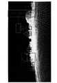
図2は、本発明の一実施例に基づいて、二次元画像データと三次元ポイントクラウドデータとの整列処理を説明する模式図である。図1、2を同時に参照すると、図2に示すように、二次元画像センサ102で取得された二次元画像データ(図2の背景画像)、および三次元センサ104で取得された三次元ポイントクラウドデータ(図2の点状画像)を、整列アルゴリズムにより融合して生成した三次元画像データ画像である。 FIG. 2 is a schematic diagram illustrating an alignment process between two-dimensional image data and three-dimensional point cloud data based on an embodiment of the present invention. Referring to FIGS. 1 and 2 at the same time, as shown in FIG. 2, the two-dimensional image data (background image in FIG. 2) acquired by the two-
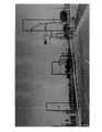
二次元画像センサ102で取得された二次元画像データについて、静的オブジェクト識別モジュール112は、二次元画像データの少なくとも1つの静的オブジェクトを判定や識別することができる。一つの例として、静的オブジェクト識別モジュール112は、静的オブジェクトの検出に特化したディープ学習モジュールを含み、静的オブジェクトの種類、例えば道路標識、建物、変圧器ボックス、道路、歩道、橋梁、樹木、電柱、ジャージーバリア等を識別することができる。静的オブジェクト識別モジュール112のディープ学習モジュールまたはディープニューラルネットワーク(Deep Neural Network)は、画像識別アルゴリズムにより画像内の静的オブジェクトを識別する。現在、従来のオブジェクト識別アルゴリズム、例えばオブジェクト輪郭追跡アルゴリズムが知られており、ここでは詳細を省略する。静的オブジェクト識別モジュール112が静的オブジェクトを検出するサーチウィンドー(search window)は、オブジェクトのモデル、フレームまたは境界ボックス(bounding box、BB)等に対応することができる。図3は、本発明の一実施例に基づいて、二次元画像センサから静的オブジェクトを識別することを説明する模式図である。図3に示すように、静的オブジェクト識別アルゴリズムに基づいて二次元画像データにおける各静的オブジェクトを識別し、二次元画像データにおける各静的オブジェクトを境界ボックスで標示する。図3の境界ボックスのように、境界ボックス毎に静的オブジェクト毎の情報が含まれている。例えば、オブジェクトの種類、オブジェクトの長さ、オブジェクトの幅、および二次元画像データにおける位置等の情報が標示されている。 With respect to the two-dimensional image data acquired by the two-
二次元画像データにおける各静的オブジェクトを得た後、上記各静的オブジェクトの情報(例えば種類、長さ、幅、位置等の情報)に基づいて、三次元画像データから各静的オブジェクトの三次元ポイントクラウドデータ(X、Y、Zデータ)を取得することができる。静的オブジェクトのそれぞれは、三次元画像データにおけるオブジェクトの大きさに対応する。このため、それぞれの静的オブジェクトは、複数の三次元ポイントクラウドデータ(ディープ情報)を含んでもよい。図4は、図3の実施例に基づいて、各静的オブジェクトを識別した後、三次元画像データから各静的オブジェクトの三次元ポイントクラウドデータを取得したことを説明する模式図である。図3、4を参照すると、図3の境界ボックスで標示された各静的オブジェクト(交通信号、街灯及び道路)の情報に基づいて、対応する三次元画像データにおける各静的オブジェクトの三次元ポイントクラウドデータを取得する。 After obtaining each static object in the two-dimensional image data, the third order of each static object is obtained from the three-dimensional image data based on the information of each static object (for example, information such as type, length, width, position, etc.). Original point cloud data (X, Y, Z data) can be acquired. Each of the static objects corresponds to the size of the object in the 3D image data. Therefore, each static object may include a plurality of 3D point cloud data (deep information). FIG. 4 is a schematic diagram illustrating that after identifying each static object, the three-dimensional point cloud data of each static object is acquired from the three-dimensional image data based on the embodiment of FIG. Referring to FIGS. 3 and 4, the 3D points of each static object in the corresponding 3D image data based on the information of each static object (traffic signal, street light and road) marked by the boundary box of FIG. Get cloud data.
次に、乗物上の乗物測位システム100が各静的オブジェクトの三次元ポイントクラウドデータを取得すると、乗物測位システム100の測位モジュール114は、静的オブジェクトの三次元ポイントクラウドデータに基づいて、測位アルゴリズム、例えば三点測位アルゴリズム、若しくは現在の三次元ポイントクラウドデータと地図ポイントクラウドデータとを反復比較し、乗物ポイントクラウドデータと少なくとも1つの静的オブジェクトの三次元ポイントクラウドデータとの最小平均二乗距離(mean squared distances;MSD)の最適化算出により、乗物と静的オブジェクトとの乗物相対座標を算出し、乗物の測位を達成する。一つの実施例において、上記の乗物相対座標を予め記憶された所定の地図情報にマッピングすることができる。該所定の地図情報は、3DポイントクラウドデータとGPS絶対座標情報とを含むため、乗物相対座標と所定の地図情報とにより座標の定義と変換を行うことで、乗物の三次元乗物絶対座標を取得することができる。 Next, when the
他の実施例において、各静的オブジェクトの三次元ポイントクラウドデータを予め記憶された地図情報にマッピングすることができる。該所定の地図情報は、3DポイントクラウドデータとGPS絶対座標とを含むため、静的オブジェクトの三次元ポイントクラウドデータと所定の地図情報の静的三次元オブジェクトとを比較することにより、静的オブジェクトの三次元オブジェクト絶対座標を取得する。このように、乗物の所定の地図情報での位置を推定することができ、乗物の三次元乗物絶対座標を取得することができる。 In another embodiment, the 3D point cloud data of each static object can be mapped to the map information stored in advance. Since the predetermined map information includes 3D point cloud data and GPS absolute coordinates, the static object is obtained by comparing the 3D point cloud data of the static object with the static 3D object of the predetermined map information. Get the absolute coordinates of the 3D object of. In this way, the position of the vehicle on the predetermined map information can be estimated, and the three-dimensional vehicle absolute coordinates of the vehicle can be obtained.
本発明に係る実施例において、二次元画像センサ102で取得された二次元画像データは、一般的に、物体表面の反射特性のみに基づいて、実際の世界が画像平面に投影されてなる情報を提供して、物体の輪郭、境界、テクスチャー等の特徴を取得する。このため、二次元情報を基にした識別アルゴリズムにより実際の三次元物体を識別した場合、オブジェクトの三次元空間での正確な位置に位置決めすることができず、乗物位置を正確に測位できない。三次元センサ104は、オブジェクトの三次元ポイントクラウドデータを取得することができるが、オブジェクトの種類を識別することができない。従って、二次元画像センサ102及び三次元センサ104という2種の異質センサの特性と利点を組み合わせて、静的オブジェクトの三次元ポイントクラウドデータを検出することにより、乗物のリアルタイム測位を行うことができる。 In the embodiment according to the present invention, the two-dimensional image data acquired by the two-
本発明において、動的オブジェクトではなく、静的オブジェクトを静的オブジェクト識別モジュール112により識別する理由は、動的オブジェクトに対して、静的オブジェクトのほうがより容易に検出や識別でき、形状と色の変化も動的オブジェクトと比べて少なくなるため、静的オブジェクト識別モジュール112では、少ないトレーニングデータと低いモデル複雑性で、良好な静的オブジェクト識別率を達成できるからである。
このように、二次元画像センサ102の二次元画像データと三次元センサ104の三次元ポイントクラウドデータとを組み合わせて、静的オブジェクト識別モジュール112により各静的オブジェクトを識別し、各静的オブジェクトの三次元ポイントクラウドデータを取得することにより、乗物と静的オブジェクトの乗物相対座標を算出でき、乗物の測位を達成できる。In the present invention, the reason why static objects are identified by the static
In this way, the 2D image data of the
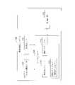
図5は、本発明の一実施例に基づいて乗物測位システムの作動フローを説明する模式図である。 FIG. 5 is a schematic diagram illustrating an operation flow of a vehicle positioning system based on an embodiment of the present invention.
図5に示すように、ステップS501において、二次元画像センサ102は、二次元画像データを取得する。この二次元画像データは、少なくとも1つの静的オブジェクトのシーンを含む。ステップS503において、三次元センサ104は、三次元ポイントクラウドデータを取得する。ステップS505において、整列モジュール110は整列アルゴリズムにより二次元画像データと三次元ポイントクラウドデータとを融合させることで三次元画像データを取得する。ステップS507において、静的オブジェクト識別モジュール112は、二次元画像データから少なくとも1つの静的オブジェクトを識別する。ステップS509において、各静的オブジェクトに基づいて三次元画像データから各静的オブジェクトの三次元ポイントクラウドデータを取得する。ステップS511において、測位モジュール114は、静的オブジェクトの三次元ポイントクラウドデータに基づいて乗物の乗物相対座標を算出する。測位アルゴリズムにより、静的オブジェクトの三次元ポイントクラウドデータに基づいて乗物の三次元画像データでの三次元乗物相対座標を算出することができる。 As shown in FIG. 5, in step S501, the two-
図6は、本発明の一実施例に基づいて、乗物600が乗物測位システムと直接(direct)または間接(indirect)に通信可能なシステム通信を説明する模式図である。図6に示すように、乗物測位システムのプロセッサー606と記憶装置608は、乗物600に搭載、または乗物600より遠隔する他の地点/場所に設置することができる。乗物測位システムのプロセッサー606と記憶装置608とを遠隔地に設置すると、乗物600は、遠隔地のプロセッサー606及び記憶装置608と通信する能力を有する。この実施例において、乗物600は自動車であるが、本発明はこれに限定されるものではない。 FIG. 6 is a schematic diagram illustrating system communication in which a
一つまたは複数の二次元画像センサ602、及び一つまたは複数の三次元センサ604は乗物600に設けられる。この実施例において、乗物測位システムは、上記図1~4の機能と演算を実行し、乗物600の二次元画像センサ602で取得された二次元画像データを三次元センサ604で取得された三次元ポイントクラウドデータと整列させることで三次元画像データを取得し、二次元画像データの各静的オブジェクトに基づいて三次元画像データから各静的オブジェクトの三次元ポイントクラウドデータを取得し、静的オブジェクトの三次元ポイントクラウドデータにより乗物の乗物相対座標を算出し、乗物の測位を達成できる。 One or more
上記のように、本発明に係る乗物、乗物測位システム及び乗物測位方法によれば、乗物に二次元画像センサ及び三次元センサという2種の異質センサと組み合わせて三次元画像データを取得するとともに、二次元画像データの静的オブジェクトを識別した後、三次元画像データから各静的オブジェクトの三次元ポイントクラウドデータを取得し、乗物と静的オブジェクトとの乗物相対座標を算出して、所定の地図情報にマッピングすることで乗物相対座標を得ることができ、乗物の測位を達成する。これにより、乗物が静的オブジェクトの検出に特化したディープ学習モジュールにより、静的オブジェクト画像識別時間を短縮し、さらに静的オブジェクトの三次元ポイントクラウドデータだけで済むため、三次元ポイントクラウドデータの演算量を低減することができ、乗物の正確な測位を達成することができる。 As described above, according to the vehicle, vehicle positioning system, and vehicle positioning method according to the present invention, the vehicle is combined with two types of heterogeneous sensors, a two-dimensional image sensor and a three-dimensional sensor, to acquire three-dimensional image data, and at the same time, obtain three-dimensional image data. After identifying the static object of the 2D image data, the 3D point cloud data of each static object is acquired from the 3D image data, the vehicle relative coordinates of the vehicle and the static object are calculated, and a predetermined map is obtained. Vehicle relative coordinates can be obtained by mapping to information, and vehicle positioning is achieved. As a result, the vehicle uses a deep learning module that specializes in detecting static objects, which shortens the static object image identification time and requires only 3D point cloud data for static objects. The amount of calculation can be reduced, and accurate positioning of the vehicle can be achieved.
上述したものは、本発明の実施例に過ぎず、本発明の実施の範囲を限定するためのものではなく、所属する技術分野において通常知識を有する者であれば、本発明の主旨を逸脱しない範囲でいくつの修正や変更することが可能であり、本発明の特許請求の範囲は添付の請求の範囲により限定されているものである。 The above-mentioned matters are merely examples of the present invention, and are not intended to limit the scope of implementation of the present invention. Any number of amendments or changes may be made within the scope, and the scope of the claims of the present invention is limited by the scope of the attached claims.
100 乗物測位システム
102 二次元画像センサ
104 三次元センサ
106 プロセッサー
108 記憶回路
110 整列モジュール
112 静的オブジェクト識別モジュール
114 測位モジュール
600 乗物
602 二次元画像センサ
604 三次元センサ
606 プロセッサー
608 記憶装置
S501、S503、S505、S507、S509、S511 乗物測位システム作動のステップ100
Claims (16)
Translated fromJapanese二次元画像データを取得する二次元画像センサと、
三次元ポイントクラウドデータを取得する三次元センサと、
該二次元画像センサ及び該三次元センサに接続されたプロセッサーであって、
該三次元ポイントクラウドデータを該二次元画像データの画素点にマッピングして、該二次元画像データと該三次元ポイントクラウドデータとを融合することで、三次元画像データを生成する整列モジュールと、
該二次元画像データから少なくとも1つの静的オブジェクトを識別し、該二次元画像データから識別された該少なくとも1つの静的オブジェクトの各静的オブジェクトに基づいて、該三次元画像データから該静的オブジェクトの三次元ポイントクラウドデータを取得する静的オブジェクト識別モジュールと、
該静的オブジェクトの該三次元ポイントクラウドデータに基づいて、乗物の乗物相対座標を算出する測位モジュールと、
に、少なくとも適用するように構成されたプロセッサーと、
を備えることを特徴とする乗物測位システム。It ’s a vehicle positioning system.
A 2D image sensor that acquires 2D image data,
3D point cloud 3D sensor that acquires cloud data and
The two-dimensional image sensor and the processor connected to the three-dimensional sensor.
An alignment module that generates 3D image data by mapping the 3D point cloud data to the pixel points of the 2D image data and fusing the 2D image data with the 3D point cloud data.
At least one static object is identified from the two-dimensional image data, and the static is derived from the three-dimensional image data based on each static object of the at least one static object identified from the two-dimensional image data. A static object identification module that acquires 3D point cloud data of an object,
A positioning module that calculates the vehicle relative coordinates of the vehicle based on the 3D point cloud data of the static object, and
At least with a processor configured to apply,
A vehicle positioning system characterized by being equipped with.
前記乗物測位システムは、二次元画像センサと、三次元センサと、プロセッサーとを備え、
前記プロセッサーは、整列モジュールと、静的オブジェクト識別モジュールと、測位モジュールとに適用するように構成され、
前記乗物測位方法は、
前記二次元画像センサにより、二次元画像データを取得する工程と、
前記三次元センサにより、三次元ポイントクラウドデータを取得する工程と、
前記整列モジュールにより、該三次元ポイントクラウドデータを該二次元画像データの画素点にマッピングして、該二次元画像データと該三次元ポイントクラウドデータとを融合し、三次元画像データを生成する工程と、
前記静的オブジェクト識別モジュールにより、該二次元画像データから少なくとも1つの静的オブジェクトを識別し、該二次元画像データから識別された該静的オブジェクトに基づいて該三次元画像データから該静的オブジェクトの三次元ポイントクラウドデータを取得する工程と、
前記測位モジュールにより、該静的オブジェクトの該三次元ポイントクラウドデータに基づいて、乗物の乗物相対座標を算出する工程と、
を備えることを特徴とする乗物測位方法。It is a vehicle positioning method applied to the vehicle positioning system.
The vehicle positioning system includes a two-dimensional image sensor, a three-dimensional sensor, and a processor.
The processor is configured to apply to an alignment module, a static object identification module, and a positioning module.
The vehicle positioning method is
The process of acquiring 2D image databy the 2D image sensor and
The process of acquiring 3D point cloud data usingthe 3D sensor ,
A step of mapping the 3D point cloud data to the pixel points of the 2D image databy the alignment module, fusing the 2D image data and the 3D point cloud data, and generating 3D image data. When,
Thestatic object identification module identifies at least one static object from the two-dimensional image data, and the static object is derived from the three-dimensional image data based on the static object identifiedfrom the two-dimensional image data. 3D point cloud data acquisition process and
The step of calculating the vehicle relative coordinates of the vehicle based on the three-dimensional point cloud dataof the static object by the positioning module, and
A vehicle positioning method characterized by comprising.
二次元画像データを取得する二次元画像センサと、
三次元ポイントクラウドデータを取得する三次元センサと、
該二次元画像センサ及び該三次元センサに接続されたプロセッサーであって、
該三次元ポイントクラウドデータを該二次元画像データの画素点にマッピングして、該二次元画像データと該三次元ポイントクラウドデータとを融合することで、三次元画像データを生成する整列モジュールと、
該二次元画像データから少なくとも1つの静的オブジェクトを識別し、該二次元画像データから識別された該少なくとも1つの静的オブジェクトの各静的オブジェクトに基づいて、該三次元画像データから該静的オブジェクトの三次元ポイントクラウドデータを取得する静的オブジェクト識別モジュールと、
該静的オブジェクトの該三次元ポイントクラウドデータに基づいて、該乗物の乗物相対座標を算出するための測位モジュールと、
に、少なくとも適用するように構成されたプロセッサーと、
を備えることを特徴とする乗物。A vehicle with a vehicle positioning system installed.
A 2D image sensor that acquires 2D image data,
3D point cloud 3D sensor that acquires cloud data and
The two-dimensional image sensor and the processor connected to the three-dimensional sensor.
An alignment module that generates 3D image data by mapping the 3D point cloud data to the pixel points of the 2D image data and fusing the 2D image data with the 3D point cloud data.
At least one static object is identified from the two-dimensional image data, and the static is derived from the three-dimensional image data based on each static object of the at least one static object identified from the two-dimensional image data. A static object identification module that acquires 3D point cloud data of an object,
A positioning module for calculating the vehicle relative coordinates of the vehicle based on the 3D point cloud data of the static object, and
At least with a processor configured to apply,
A vehicle characterized by being equipped with.
Applications Claiming Priority (4)
| Application Number | Priority Date | Filing Date | Title |
|---|---|---|---|
| US201862773124P | 2018-11-29 | 2018-11-29 | |
| US62/773,124 | 2018-11-29 | ||
| TW108112604ATWI754808B (en) | 2018-11-29 | 2019-04-11 | Vehicle, vehicle positioning system, and vehicle positioning method |
| TW108112604 | 2019-04-11 |
Publications (2)
| Publication Number | Publication Date |
|---|---|
| JP2020085886A JP2020085886A (en) | 2020-06-04 |
| JP7073315B2true JP7073315B2 (en) | 2022-05-23 |
Family
ID=70849764
Family Applications (1)
| Application Number | Title | Priority Date | Filing Date |
|---|---|---|---|
| JP2019136998AActiveJP7073315B2 (en) | 2018-11-29 | 2019-07-25 | Vehicles, vehicle positioning systems, and vehicle positioning methods |
Country Status (3)
| Country | Link |
|---|---|
| US (1) | US11024055B2 (en) |
| JP (1) | JP7073315B2 (en) |
| CN (1) | CN111238494B (en) |
Families Citing this family (27)
| Publication number | Priority date | Publication date | Assignee | Title |
|---|---|---|---|---|
| DE102018209607A1 (en)* | 2018-06-14 | 2019-12-19 | Volkswagen Aktiengesellschaft | Method and device for determining a position of a motor vehicle |
| CN110148196B (en)* | 2018-09-12 | 2022-03-25 | 腾讯大地通途(北京)科技有限公司 | Image processing method and device and related equipment |
| DE102018221625A1 (en)* | 2018-12-13 | 2020-06-18 | Robert Bosch Gmbh | Transfer of additional information between camera systems |
| JP7086111B2 (en)* | 2019-01-30 | 2022-06-17 | バイドゥドットコム タイムズ テクノロジー (ベイジン) カンパニー リミテッド | Feature extraction method based on deep learning used for LIDAR positioning of autonomous vehicles |
| WO2021014846A1 (en)* | 2019-07-22 | 2021-01-28 | 日本電気株式会社 | Information processing device, data generation method, and non-transitory computer-readable medium having program stored thereon |
| KR102826629B1 (en)* | 2019-11-20 | 2025-06-27 | 팅크웨어(주) | Method, apparatus, computer program and computer readable recording medium for producing high definition map |
| KR20210071584A (en)* | 2019-12-06 | 2021-06-16 | 팅크웨어(주) | Method and apparatus for determining location by correcting Global Navigation Satellite System based location and electronic device thereof |
| US11790555B2 (en)* | 2020-01-17 | 2023-10-17 | Electronics And Telecommunications Research Institute | System and method for fusion recognition using active stick filter |
| US20230300311A1 (en)* | 2020-06-15 | 2023-09-21 | Guangdong Launca Medical Device Tech. Co., Ltd. | Lens, three-dimensional imaging module, apparatus, method, device and storage medium |
| CN111787301A (en)* | 2020-06-15 | 2020-10-16 | 广东朗呈医疗器械科技有限公司 | Lens, three-dimensional imaging method, device, equipment and storage medium |
| US11222215B1 (en)* | 2020-07-13 | 2022-01-11 | Toyota Motor Engineering & Manufacturing North America, Inc. | Identifying a specific object in a two-dimensional image of objects |
| US11756317B2 (en)* | 2020-09-24 | 2023-09-12 | Argo AI, LLC | Methods and systems for labeling lidar point cloud data |
| CN112200868A (en)* | 2020-09-30 | 2021-01-08 | 深兰人工智能(深圳)有限公司 | Positioning method, device and vehicle |
| TWI758980B (en)* | 2020-11-30 | 2022-03-21 | 財團法人金屬工業研究發展中心 | Environment perception device and method of mobile vehicle |
| CN112666569B (en)* | 2020-12-01 | 2023-03-24 | 天津优控智行科技有限公司 | Compression method of laser radar continuous point cloud of unmanned system |
| US11995157B2 (en)* | 2020-12-04 | 2024-05-28 | Caterpillar Inc. | Intelligent LiDAR scanning |
| AU2021102368A4 (en)* | 2021-01-22 | 2021-06-24 | 4AI Systems Holdings Pty Ltd | A Sensor Device for Vehicles |
| CN112800159B (en) | 2021-01-25 | 2023-10-31 | 北京百度网讯科技有限公司 | Map data processing method and device |
| CN113064193B (en)* | 2021-03-25 | 2022-12-16 | 上海智能新能源汽车科创功能平台有限公司 | Combined positioning system based on vehicle road cloud cooperation |
| KR102656646B1 (en)* | 2021-08-26 | 2024-04-12 | (주)서울로보틱스 | Method for detecting installation abnormality of sensing device and sensing device of performing the same |
| US12190607B2 (en)* | 2021-10-21 | 2025-01-07 | Ford Global Technologies, Llc | System and method for simultaneous online LIDAR intensity calibration and road marking change detection |
| US12046049B2 (en)* | 2021-12-01 | 2024-07-23 | Motional Ad Llc | Automatically detecting traffic signals using sensor data |
| US12165340B2 (en)* | 2022-01-18 | 2024-12-10 | Pony Ai Inc. | Hardware-based point-cloud matching |
| CN114473309A (en)* | 2022-03-18 | 2022-05-13 | 南京欧睿三维科技有限公司 | Welding position identification method for automatic welding system and automatic welding system |
| CN115330923B (en)* | 2022-08-10 | 2023-11-14 | 小米汽车科技有限公司 | Point cloud data rendering method and device, vehicle, readable storage medium and chip |
| JP2025037687A (en)* | 2023-09-06 | 2025-03-18 | 京セラ株式会社 | Electronic device, system, control method, and program |
| TWI889317B (en)* | 2024-04-29 | 2025-07-01 | 國立臺北科技大學 | 3d around view monitoring system |
Citations (3)
| Publication number | Priority date | Publication date | Assignee | Title |
|---|---|---|---|---|
| WO2018038131A1 (en) | 2016-08-26 | 2018-03-01 | パナソニック インテレクチュアル プロパティ コーポレーション オブ アメリカ | Three-dimensional information processing method and three-dimensional information processing apparatus |
| WO2018159168A1 (en) | 2017-02-28 | 2018-09-07 | Mitsubishi Electric Corporation | System and method for virtually-augmented visual simultaneous localization and mapping |
| JP2018180181A (en) | 2017-04-10 | 2018-11-15 | 凸版印刷株式会社 | Laser scanning device |
Family Cites Families (42)
| Publication number | Priority date | Publication date | Assignee | Title |
|---|---|---|---|---|
| CN102138163B (en)* | 2008-08-29 | 2014-04-30 | 三菱电机株式会社 | Bird's-eye view image generation device and bird's-eye view image generation method |
| TW201110928A (en) | 2009-09-16 | 2011-04-01 | Univ Chang Gung | Optical tracking apparatus and its positioning method |
| TWI403690B (en) | 2009-10-26 | 2013-08-01 | Ind Tech Res Inst | Self-positioning device and method thereof |
| CN102072725B (en)* | 2010-12-16 | 2012-11-07 | 唐粮 | Spatial three-dimension (3D) measurement method based on laser point cloud and digital measurable images |
| TWI431250B (en) | 2011-03-01 | 2014-03-21 | Navigation device for integrated traffic image recording and navigation information | |
| JP6233706B2 (en) | 2013-04-02 | 2017-11-22 | パナソニックIpマネジメント株式会社 | Autonomous mobile device and self-position estimation method of autonomous mobile device |
| EP3456597B1 (en) | 2013-04-11 | 2023-06-07 | Waymo Llc | Methods and systems for detecting weather conditions using vehicle onboard sensors |
| TWI535589B (en) | 2013-09-24 | 2016-06-01 | Active automatic driving assistance system and method | |
| JP6381100B2 (en)* | 2013-11-07 | 2018-08-29 | 株式会社環境総合テクノス | Three-dimensional subsurface diagnosis system and three-dimensional subsurface diagnosis method |
| TWI534764B (en) | 2014-01-10 | 2016-05-21 | 財團法人工業技術研究院 | Apparatus and method for vehicle positioning |
| US10061027B2 (en) | 2014-02-25 | 2018-08-28 | Adsys Controls, Inc. | Laser navigation system and method |
| GB201409625D0 (en) | 2014-05-30 | 2014-07-16 | Isis Innovation | Vehicle localisation |
| US20160047888A1 (en) | 2014-08-15 | 2016-02-18 | Richard D. Roberts | Vehicle positioning |
| CN104268935A (en)* | 2014-09-18 | 2015-01-07 | 华南理工大学 | Feature-based airborne laser point cloud and image data fusion system and method |
| US9378554B2 (en)* | 2014-10-09 | 2016-06-28 | Caterpillar Inc. | Real-time range map generation |
| JP6284240B2 (en)* | 2015-02-03 | 2018-02-28 | 国立大学法人 東京大学 | Structure information provision system |
| US9715016B2 (en)* | 2015-03-11 | 2017-07-25 | The Boeing Company | Real time multi dimensional image fusing |
| HK1252900A1 (en)* | 2015-05-20 | 2019-06-06 | 三菱电机株式会社 | Point-cloud-image generation device and display system |
| US10121082B2 (en) | 2015-10-07 | 2018-11-06 | Honda Motor Co., Ltd. | System and method for providing laser camera fusion for identifying and tracking a traffic participant |
| JP6682833B2 (en) | 2015-12-04 | 2020-04-15 | トヨタ自動車株式会社 | Database construction system for machine learning of object recognition algorithm |
| CN105512646B (en)* | 2016-01-19 | 2019-03-01 | 腾讯科技(深圳)有限公司 | A kind of data processing method, device and terminal |
| CN105676643B (en) | 2016-03-02 | 2018-06-26 | 厦门大学 | A kind of intelligent automobile turns to and braking self-adaptive wavelet base method |
| WO2017159382A1 (en) | 2016-03-16 | 2017-09-21 | ソニー株式会社 | Signal processing device and signal processing method |
| JP6368959B2 (en) | 2016-05-19 | 2018-08-08 | 本田技研工業株式会社 | Vehicle control system, vehicle control method, and vehicle control program |
| CN106097348B (en)* | 2016-06-13 | 2019-03-05 | 大连理工大学 | A fusion method of 3D laser point cloud and 2D image |
| CN105928457B (en)* | 2016-06-21 | 2019-10-11 | 大连理工大学 | An omnidirectional three-dimensional laser color scanning system and method thereof |
| CN106407947B (en) | 2016-09-29 | 2019-10-22 | 百度在线网络技术(北京)有限公司 | Target object recognition methods and device for automatic driving vehicle |
| CN106707293B (en) | 2016-12-01 | 2019-10-29 | 百度在线网络技术(北京)有限公司 | Obstacle recognition method and device for vehicle |
| US10078334B2 (en) | 2016-12-07 | 2018-09-18 | Delphi Technologies, Inc. | Vision sensing compensation |
| US10754035B2 (en) | 2017-01-17 | 2020-08-25 | Aptiv Technologies Limited | Ground classifier system for automated vehicles |
| US20180211119A1 (en) | 2017-01-23 | 2018-07-26 | Ford Global Technologies, Llc | Sign Recognition for Autonomous Vehicles |
| CN110235026A (en)* | 2017-01-26 | 2019-09-13 | 御眼视觉技术有限公司 | Vehicle Navigation Based on Aligned Image and Lidar Information |
| CN106932780A (en)* | 2017-03-14 | 2017-07-07 | 北京京东尚科信息技术有限公司 | Object positioning method, device and system |
| CN107194983B (en)* | 2017-05-16 | 2018-03-09 | 华中科技大学 | A kind of three-dimensional visualization method and system based on a cloud and image data |
| CN108196535B (en)* | 2017-12-12 | 2021-09-07 | 清华大学苏州汽车研究院(吴江) | Automatic driving system based on reinforcement learning and multi-sensor fusion |
| CN108151750B (en)* | 2017-12-13 | 2020-04-14 | 西华大学 | Positioning method and device |
| CN108225334B (en)* | 2018-01-17 | 2020-10-16 | 泰瑞天际科技(北京)有限公司 | Positioning method and device based on three-dimensional live-action data |
| US10854011B2 (en)* | 2018-04-09 | 2020-12-01 | Direct Current Capital LLC | Method for rendering 2D and 3D data within a 3D virtual environment |
| US10726567B2 (en)* | 2018-05-03 | 2020-07-28 | Zoox, Inc. | Associating LIDAR data and image data |
| CN108622093B (en) | 2018-05-04 | 2020-08-04 | 奇瑞汽车股份有限公司 | Lane keeping control method and device for intelligent vehicle |
| CN108830159A (en) | 2018-05-17 | 2018-11-16 | 武汉理工大学 | A kind of front vehicles monocular vision range-measurement system and method |
| DE102018209607A1 (en)* | 2018-06-14 | 2019-12-19 | Volkswagen Aktiengesellschaft | Method and device for determining a position of a motor vehicle |
- 2019
- 2019-05-06CNCN201910370531.2Apatent/CN111238494B/enactiveActive
- 2019-07-11USUS16/508,471patent/US11024055B2/enactiveActive
- 2019-07-25JPJP2019136998Apatent/JP7073315B2/enactiveActive
Patent Citations (3)
| Publication number | Priority date | Publication date | Assignee | Title |
|---|---|---|---|---|
| WO2018038131A1 (en) | 2016-08-26 | 2018-03-01 | パナソニック インテレクチュアル プロパティ コーポレーション オブ アメリカ | Three-dimensional information processing method and three-dimensional information processing apparatus |
| WO2018159168A1 (en) | 2017-02-28 | 2018-09-07 | Mitsubishi Electric Corporation | System and method for virtually-augmented visual simultaneous localization and mapping |
| JP2018180181A (en) | 2017-04-10 | 2018-11-15 | 凸版印刷株式会社 | Laser scanning device |
Also Published As
| Publication number | Publication date |
|---|---|
| US20200175720A1 (en) | 2020-06-04 |
| CN111238494A (en) | 2020-06-05 |
| JP2020085886A (en) | 2020-06-04 |
| CN111238494B (en) | 2022-07-19 |
| US11024055B2 (en) | 2021-06-01 |
Similar Documents
| Publication | Publication Date | Title |
|---|---|---|
| JP7073315B2 (en) | Vehicles, vehicle positioning systems, and vehicle positioning methods | |
| US11675084B2 (en) | Determining yaw error from map data, lasers, and cameras | |
| US11474247B2 (en) | Methods and systems for color point cloud generation | |
| CN108572663B (en) | Target tracking | |
| CN113673282B (en) | Target detection method and device | |
| CN111986506B (en) | Mechanical parking space parking method based on multi-vision system | |
| EP3283843B1 (en) | Generating 3-dimensional maps of a scene using passive and active measurements | |
| CN110119698B (en) | Method, apparatus, device and storage medium for determining the state of an object | |
| JP2022166143A (en) | System and method for determining navigation parameters | |
| JP2020525809A (en) | System and method for updating high resolution maps based on binocular images | |
| JP2021508815A (en) | Systems and methods for correcting high-definition maps based on the detection of obstructing objects | |
| US20180273031A1 (en) | Travel Control Method and Travel Control Apparatus | |
| CN107246868A (en) | A kind of collaborative navigation alignment system and navigation locating method | |
| CN111856491A (en) | Method and apparatus for determining the geographic location and orientation of a vehicle | |
| TWI754808B (en) | Vehicle, vehicle positioning system, and vehicle positioning method | |
| US20210180958A1 (en) | Graphic information positioning system for recognizing roadside features and method using the same | |
| CN117677972A (en) | System and method for road segment drawing | |
| KR102857655B1 (en) | Apparatus and method for correcting bias in sensor | |
| US12135565B2 (en) | Adaptive sensor control | |
| AU2018102199A4 (en) | Methods and systems for color point cloud generation | |
| JP7337617B2 (en) | Estimation device, estimation method and program | |
| CN111833443B (en) | Landmark Position Reconstruction in Autonomous Machine Applications | |
| JP7302966B2 (en) | moving body | |
| WO2022133986A1 (en) | Accuracy estimation method and system | |
| Jarnea et al. | Advanced driver assistance system for overtaking maneuver on a highway |
Legal Events
| Date | Code | Title | Description |
|---|---|---|---|
| A621 | Written request for application examination | Free format text:JAPANESE INTERMEDIATE CODE: A621 Effective date:20190725 | |
| A131 | Notification of reasons for refusal | Free format text:JAPANESE INTERMEDIATE CODE: A131 Effective date:20201005 | |
| A131 | Notification of reasons for refusal | Free format text:JAPANESE INTERMEDIATE CODE: A131 Effective date:20210510 | |
| A521 | Request for written amendment filed | Free format text:JAPANESE INTERMEDIATE CODE: A523 Effective date:20210803 | |
| A131 | Notification of reasons for refusal | Free format text:JAPANESE INTERMEDIATE CODE: A131 Effective date:20220104 | |
| A521 | Request for written amendment filed | Free format text:JAPANESE INTERMEDIATE CODE: A523 Effective date:20220401 | |
| TRDD | Decision of grant or rejection written | ||
| A01 | Written decision to grant a patent or to grant a registration (utility model) | Free format text:JAPANESE INTERMEDIATE CODE: A01 Effective date:20220411 | |
| A61 | First payment of annual fees (during grant procedure) | Free format text:JAPANESE INTERMEDIATE CODE: A61 Effective date:20220511 | |
| R150 | Certificate of patent or registration of utility model | Ref document number:7073315 Country of ref document:JP Free format text:JAPANESE INTERMEDIATE CODE: R150 | |
| R250 | Receipt of annual fees | Free format text:JAPANESE INTERMEDIATE CODE: R250 |