JP7072380B2 - How to make a bottle can - Google Patents
How to make a bottle canDownload PDFInfo
- Publication number
- JP7072380B2 JP7072380B2JP2017245160AJP2017245160AJP7072380B2JP 7072380 B2JP7072380 B2JP 7072380B2JP 2017245160 AJP2017245160 AJP 2017245160AJP 2017245160 AJP2017245160 AJP 2017245160AJP 7072380 B2JP7072380 B2JP 7072380B2
- Authority
- JP
- Japan
- Prior art keywords
- thickness
- diameter
- bottle
- cylindrical
- flange
- Prior art date
- Legal status (The legal status is an assumption and is not a legal conclusion. Google has not performed a legal analysis and makes no representation as to the accuracy of the status listed.)
- Active
Links
Images


Landscapes
- Containers Having Bodies Formed In One Piece (AREA)
Description
Translated fromJapanese本発明は、DIプレス工程において成形された底部と円筒部とを有する有底円筒体の円筒部の底部とは反対側部分に、ボトルネック成形工程において肩部と首部およびキャップ取付部とが成形された缶本体を有するボトル缶の製造方法に関するものである。 In the present invention, a shoulder portion, a neck portion, and a cap mounting portion are molded in a bottleneck molding step on a portion opposite to the bottom portion of the cylindrical portion of a bottomed cylinder having a bottom portion and a cylindrical portion molded in the DI press process. It relates to a method of manufacturing a bottle can having a molded can body.
このようなボトル缶の製造方法として、例えば特許文献1には、金属(アルミニウム合金)製の缶本体を形成する段階であって、缶本体は底部を有し、底部は側壁の下部に続いており、側壁は絞り且つ壁しごき加工されて、壁部に続いており、壁部は開口した上端に続いており、缶本体の壁部は側壁の下部より厚さが厚く形成されている缶本体を形成する段階と、壁部に複数回のネッキング加工を施して切頭円錐形部を形成する段階であって、切頭円錐形部は、缶本体の壁部よりも厚さが大きく、上部に缶本体の直径よりも小さい直径の首部を有し、首部が、上端開口近傍の円筒部に続いている、切頭円錐形部を形成する段階と、金属缶の頂部にビードを形成する段階と、クロージャをねじに固定するために、ビードの下方にて円筒部上にねじを形成する段階と、ねじの下方に環状ビードを形成する段階とを含む製造方法が記載されている。 As a method for manufacturing such a bottle can, for example, in
ここで、この特許文献1には、その発明に使用する、典型的な絞り且つしごき加工した上記缶本体(DI缶)は、金属の厚さが底部断面で約0.34mm、薄肉部で約0.14mm、および厚肉部で約0.19mmであってもよいと記載されており、そのような缶本体は、直径が約76.2mmで、高さが591ml入れるために約187mm、または887ml入れるために約216mmであってもよいとも記載されている。 Here, in
また、特許文献1には、その発明に使用するための他の上記缶本体(DI缶)は、金属の厚さが底部断面で約0.25ないし0.38mm、薄肉部で約0.11ないし0.17mm、および厚肉部で約0.17ないし0.22mmであってもよいと記載されており、そのような缶は、直径が約63.5ないし88.9mm、高さが約127ないし254mmであってもよいとも記載されている。 Further, in
ここで、この特許文献1に記載された製造方法によって製造されるボトル缶は、上述のように比較的容量の大きいものであるが、日本国内で一般的に流通している310ml用のアルミニウム合金製ボトル缶は、その缶本体の胴部の直径が約66mm、缶高さが約132.6mmであって、このようなボトル缶製造用に使用される底部と円筒部を有する有底円筒体(DI缶)は、元板厚および底部の厚さが約0.345mm、円筒部のうち底部側の薄肉部であるウォール部の厚さが約0.135mm、円筒部の底部とは反対側の厚肉部であるフランジ部の厚さが約0.225mm、フランジ部とウォール部との段差は約0.090mmであり、質量は約17.5gである。 Here, the bottle can manufactured by the manufacturing method described in
また、同じく日本国内で流通している410ml用のボトル缶は、缶本体の胴部の直径が約66mm、缶高さが約164mmであって、この410ml用ボトル缶製造用に使用される有底円筒体は、元板厚および底部の厚さが約0.400mm、ウォール部の厚さが約0.130mm、フランジ部の厚さが約0.225mm、フランジ部とウォール部との段差は約0.095mmであり、質量は約21.0gである。なお、コーヒー等の飲料用のボトル缶では内容物の香りを引き立たせるために直径(おおよその数値である呼び径)が38mmのキャップに対応したキャップ取付部下端の膨出部(環状ビード)と首部との間の谷部の外径(直径)が約35.4mmのものが多いが、飲み易さを求めるためにこれよりも小径な外径(直径)が33mmのキャップに対応した谷部の外径が約30.7mmのボトル缶も流通している。 Also, the 410 ml bottle cans that are also distributed in Japan have a body diameter of about 66 mm and a can height of about 164 mm, and are used for manufacturing the 410 ml bottle cans. The bottom cylinder has a base plate thickness and a bottom thickness of about 0.400 mm, a wall portion thickness of about 0.130 mm, a flange portion thickness of about 0.225 mm, and a step between the flange portion and the wall portion. It is about 0.095 mm and weighs about 21.0 g. In addition, in the case of bottle cans for beverages such as coffee, in order to enhance the aroma of the contents, the bulging part (annular bead) at the lower end of the cap mounting part corresponding to the cap with a diameter (nominal diameter which is an approximate numerical value) of 38 mm Most of the valleys between the neck and the valley have an outer diameter (diameter) of about 35.4 mm, but the valleys with a smaller outer diameter (diameter) of 33 mm are compatible with caps for ease of drinking. Bottle cans with an outer diameter of about 30.7 mm are also available.
ところで、近年このようなボトル缶では、その缶本体を形成する金属材料の省資源化や材料製造の際の省エネルギー化のために缶本体の軽量化が求められており、例えば1缶当たり1g軽量化できただけでも、膨大な数が市場に流通するボトル缶では大幅な省資源化や省エネルギー化、あるいは缶本体のコスト削減を図ることができる。ここで、このような缶本体の軽量化を図るには、缶本体に成形される金属板の元板厚を薄くして底部やウォール部、フランジ部を薄肉化することが考えられる。 By the way, in recent years, in such bottle cans, weight reduction of the can body is required in order to save resources in the metal material forming the can body and energy saving in material manufacturing, for example, 1 g lighter per can. Even if it can be made, it is possible to significantly save resources, save energy, or reduce the cost of the can itself with bottle cans that are distributed in a huge number on the market. Here, in order to reduce the weight of the can body, it is conceivable to reduce the thickness of the base plate of the metal plate formed on the can body to reduce the thickness of the bottom portion, the wall portion, and the flange portion.
しかしながら、いたずらに金属板の元板厚を薄くしてウォール部やフランジ部を薄肉化しただけでは、金属板からカッピングプレス工程において絞り加工により成形されたカップ状素材にDIプレス工程において再絞りおよびしごき加工を施して有底円筒体を成形する際や、あるいはこうして成形された有底円筒体のフランジ部にボトルネック成形工程において肩部(上記切頭円錐形部)や首部、キャップ取付部(上記ビード、ねじ、環状ビード)を成形する際に、薄肉となったウォール部の特に座屈や変形を生じるおそれがある。特に、フランジ部の厚さが薄すぎると、ボトルネック成形工程においてキャップ取付部に割れを生じるおそれもある。 However, simply by unnecessarily thinning the original plate thickness of the metal plate to thin the wall and flange parts, the metal plate can be re-squeezed into a cup-shaped material formed by drawing in the cupping press process and re-squeezed in the DI press process. When forming a bottomed cylinder by ironing, or in the bottleneck forming process on the flange of the bottomed cylinder thus formed, the shoulder (the truncated conical part), the neck, and the cap mounting part ( When forming the bead, screw, annular bead), the thinned wall portion may be particularly buckled or deformed. In particular, if the thickness of the flange portion is too thin, the cap mounting portion may be cracked in the bottleneck molding process.
また、上述のようにDIプレス工程において有底円筒体の円筒部のうち底部側に薄肉部であるウォール部を成形するとともに、底部とは反対側には厚肉部であるフランジ部を成形するには、DIプレス機において複数のしごきダイスとの間で上記しごき加工を行うパンチの外表面に、有底円筒体のフランジ部と対応する位置に凹部を形成することによってフランジ部をウォール部よりも厚肉としている。 Further, as described above, in the DI press process, a wall portion, which is a thin-walled portion, is formed on the bottom side of the cylindrical portion of the bottomed cylinder, and a flange portion, which is a thick-walled portion, is formed on the side opposite to the bottom portion. By forming a recess on the outer surface of the punch that performs the above-mentioned ironing process between a plurality of ironing dies in a DI press machine at a position corresponding to the flange portion of the bottomed cylinder, the flange portion is formed from the wall portion. Is also thick.
ところが、薄肉化によってこれらフランジ部とウォール部との段差が大きくなると、有底円筒体からのパンチの抜け性が損なわれて抜け不良を生じ、DIプレス機を停止して抜け損ねた有底円筒体をパンチから取り外さなければならなくなり、ボトル缶の製造効率や歩留まりが著しく低下するおそれがある。また、この段差が大きいと、DIプレス工程やボトルネック成形工程において成形荷重による缶軸方向の応力が段差部分に集中して、やはり座屈や変形を生じるおそれがある。 However, when the step between the flange portion and the wall portion becomes large due to the thinning, the punch removal property from the bottomed cylinder is impaired and a removal failure occurs, and the DI press machine is stopped and the bottomed cylinder fails to be removed. The body must be removed from the punch, which can significantly reduce the manufacturing efficiency and yield of bottle cans. Further, if this step is large, stress in the can axis direction due to the molding load is concentrated on the step portion in the DI pressing process or the bottleneck forming process, and buckling or deformation may occur.
さらに、DIプレス工程により成形された有底円筒体の上端部や、この有底円筒体にボトルネック成形工程において肩部および首部が成形された缶本体の上端部には、有底円筒体の高さや缶本体の缶高さを揃えるために、これらの上端部を底部から一定の高さとなるように所定のトリム代で切断するトリミングが施される。 Further, the upper end of the bottomed cylinder formed by the DI press process and the upper end of the can body in which the shoulder and the neck are formed in the bottleneck forming process of the bottomed cylinder are formed on the bottomed cylinder. In order to make the height and the can height of the can body uniform, trimming is performed by cutting the upper end portion of these with a predetermined trim allowance so as to be a constant height from the bottom portion.
しかしながら、元板厚を薄くした金属板において、フランジ部の厚さやウォール部の厚さのバランスをとらずにDIプレス工程において有底円筒体を成形すると、この有底円筒体やボトルネック成形工程において成形された缶本体において、その上端部に必要なトリム代を確保することができなくなり、トリム代不足によって有底円筒体や缶本体を一定の高さとできずに不良品として処理せざるを得なくなる。また、このようなトリム代不足を解消するために、例えばDIプレス工程によって有底円筒体に成形される上記金属板の面積を大きくするにも限度がある。 However, in a metal plate with a thin original plate, if a bottomed cylinder is formed in the DI press process without balancing the thickness of the flange portion and the thickness of the wall portion, the bottomed cylinder or bottleneck forming process is performed. In the can body molded in the above, it is not possible to secure the necessary trim allowance at the upper end, and due to the lack of trim allowance, the bottomed cylinder and the can body cannot be made to a certain height and must be treated as defective products. You won't get it. Further, in order to solve such a shortage of trim allowance, there is a limit to increasing the area of the metal plate formed into a bottomed cylinder by, for example, a DI pressing process.
さらにまた、フランジ部の厚さが薄くなりすぎると、缶本体に飲料等を充填後にキャップを取り付けるキャッピング工程において、現行の元板厚0.400mmでのキャッピング条件のもとでキャッピングした場合、キャップ取付部に変形や座屈を生じて、一旦取り外したキャップを再びキャップ取付部にねじ込んでリシールする際のリシールトルクが増大するおそれがあることが分かった。 Furthermore, if the thickness of the flange is too thin, in the capping process of attaching the cap after filling the can body with beverages, etc., if capping is performed under the current capping conditions with a base plate thickness of 0.400 mm, the cap It has been found that the mounting portion may be deformed or buckled, and the resealing torque may increase when the cap once removed is screwed into the cap mounting portion again to reseal.
本発明は、このような背景の下になされたもので、缶本体の軽量化を図るために金属板の元板厚を薄くしても、DIプレス工程やボトルネック成形工程、キャッピング工程における座屈やパンチの抜け不良、有底円筒体の高さ不足や缶本体のトリム代不足、キャップ取付部の変形や座屈等を招くことなく有底円筒体や缶本体の成形が可能で、省資源化や省エネルギー化、炭酸ガスの削減、缶本体の軽量化を促すことができるボトル缶の製造方法を提供することを目的としている。 The present invention has been made under such a background, and even if the original plate thickness of the metal plate is reduced in order to reduce the weight of the can body, the seat in the DI pressing process, the bottleneck forming process, and the capping process. It is possible to mold the bottomed cylinder and the can body without causing bending or punch removal failure, insufficient height of the bottomed cylinder, insufficient trim allowance of the can body, deformation or buckling of the cap mounting part, etc. The purpose is to provide a method for manufacturing bottle cans that can promote resource saving, energy saving, reduction of carbon dioxide gas, and weight reduction of the can body.
ここで、本発明の発明者は、上述した直径33mmのキャップに対応した谷部の外径(直径)が約30.7mmの310ml用と410ml用のボトル缶について鋭意研究を重ねた結果、このように缶本体の軽量化を図るために金属板の元板厚を薄くした場合に、この金属板からカッピングプレス工程において絞り加工により成形したカップ状素材にDIプレス工程において再絞りおよびしごき加工を施す際、上記円筒部の底部側の薄肉部であるウォール部の厚さが0.100mm~0.130mm、上記円筒部の底部とは反対側の厚肉部であるフランジ部の厚さが0.140mm~0.200mm、上記フランジ部と上記ウォール部との段差が0.090mm以下の有底円筒体を成形することにより、DIプレス工程やボトルネック成形工程、キャッピング工程における座屈や変形、パンチの抜け不良、トリム代不足を生じることなく、所定の缶高さのボトル缶の缶本体を効率的に成形することができるとの知見を得るに至った。 Here, the inventor of the present invention has made extensive studies on bottle cans for 310 ml and 410 ml having an outer diameter (diameter) of about 30.7 mm in the valley portion corresponding to the cap having a diameter of 33 mm described above. When the original thickness of the metal plate is reduced in order to reduce the weight of the can body, the cup-shaped material formed by drawing in the cupping press process is re-squeezed and ironed in the DI press process. At the time of application, the thickness of the wall portion, which is the thin portion on the bottom side of the cylindrical portion, is 0.100 mm to 0.130 mm, and the thickness of the flange portion, which is the thick portion on the side opposite to the bottom portion of the cylindrical portion, is 0. By forming a bottomed cylinder with a step of 140 mm to 0.200 mm and a step between the flange portion and the wall portion of 0.090 mm or less, buckling and deformation in the DI pressing process, bottleneck forming process, and capping process can be achieved. It has been found that the can body of a bottle can of a predetermined can height can be efficiently molded without causing poor punch removal and insufficient trim allowance.
そこで、本発明は、このような知見に基づき、上記課題を解決して上述した目的を達成するために、第1には310ml用のボトル缶を製造するボトル缶の製造方法として、元板厚0.250mm~0.300mm、0.2%耐力が235N/mm2~265N/mm2の金属板からカッピングプレス工程において絞り加工によりカップ状素材を成形し、このカップ状素材にDIプレス工程において再絞りおよびしごき加工を施して、底部と円筒部とを有し、上記円筒部の底部側の薄肉部であるウォール部の厚さが0.100mm~0.130mm、上記円筒部の底部とは反対側の厚肉部であるフランジ部の厚さが0.140mm~0.200mm、上記フランジ部の厚さが一定とされた部分の缶軸方向の長さが42mm~60mm、上記フランジ部と上記ウォール部との段差が0.090mm以下の有底円筒体を成形し、この有底円筒体の上記フランジ部にボトルネック成形工程において、円筒状の胴部から上記底部とは反対側に向かうに従い縮径する肩部と、下端に外周側に膨出する膨出部を有するキャップ取付部とを成形することにより、上記膨出部と上記肩部との間の最小径部である谷部の外径(直径)が28.7mm~32.7mm、上記底部から上記キャップ取付部の上端までの缶高さが129.0mm~135.0mm、上記胴部の直径が64.24mm~68.24mm、質量が13.5g~16.0gの缶本体を有するボトル缶を製造することを特徴とする。なお、缶高さは131.6mm~133.6mmの範囲とされるのが好ましい。Therefore, in order to solve the above-mentioned problems and achieve the above-mentioned object based on such findings, the present invention first comprises a method for manufacturing a bottle can for producing a 310 ml bottle can, the original plate thickness. A cup-shaped material is formed from a metal plate having a 0.250 mm to 0.300 mmand 0.2% resistance of 235 N / mm2to 265 N / mm2 by drawing in a cupping press process, and the cup-shaped material is formed into this cup-shaped material in the DI press process. After re-drawing and ironing, it has a bottom and a cylindrical portion, and the thickness of the wall portion, which is a thin wall portion on the bottom side of the cylindrical portion, is 0.100 mm to 0.130 mm. The thickness of the flange portion, which is the thick portion on the opposite side, is 0.140 mm to 0.200mm, the length of the portion having the constant thickness of the flange portion in the can axis direction is 42 mm to 60 mm, and the flange portion. A bottomed cylinder having a step of 0.090 mm or less from the wall portion is formed, and in the bottleneck forming step on the flange portion of the bottomed cylinder, the cylindrical body portion is directed to the side opposite to the bottom portion. By forming a shoulder portion that shrinks in diameter according to the procedure and a cap mounting portion having a bulging portion that bulges toward the outer periphery at the lower end, a valley portion that is the minimum diameter portion between the bulging portion and the shoulder portion. The outer diameter (diameter) of the can is 28.7 mm to 32.7 mm, the can height from the bottom to the upper end of the cap mounting portion is 129.0 mm to 135.0 mm, and the diameter of the body is 64.24 mm to 68. It is characterized by producing a bottle can having a can body of 24 mmand a mass of 13.5 g to 16.0 g . The height of the can is preferably in the range of 131.6 mm to 133.6 mm.
また、同知見に基づき、本発明は、第2に410ml用のボトル缶を製造するボトル缶の製造方法として、元板厚0.270mm~0.320mm、0.2%耐力が235N/mm2~265N/mm2の金属板からカッピングプレス工程において絞り加工によりカップ状素材を成形し、このカップ状素材にDIプレス工程において再絞りおよびしごき加工を施して、底部と円筒部とを有し、上記円筒部の底部側の薄肉部であるウォール部の厚さが0.100mm~0.130mm、上記円筒部の底部とは反対側の厚肉部であるフランジ部の厚さが0.140mm~0.200mm、上記フランジ部の厚さが一定とされた部分の缶軸方向の長さが42mm~60mm、上記フランジ部と上記ウォール部との段差が0.090mm以下の有底円筒体を成形し、この有底円筒体の上記フランジ部にボトルネック成形工程において、円筒状の胴部から上記底部とは反対側に向かうに従い縮径する肩部と、下端に外周側に膨出する膨出部を有するキャップ取付部とを成形することにより、上記膨出部と上記肩部との間の最小径部である谷部の外径(直径)が28.7mm~32.7mm、上記底部から上記キャップ取付部の上端までの缶高さが160.0mm~166.5mm、上記胴部の直径が64.24mm~68.24mm、質量が16.5g~19.0gの缶本体を有するボトル缶を製造することを特徴とする。なお、缶高さは163.0mm~165.0mmの範囲とされるのが好ましい。Further, based on the same finding, the present invention secondly comprises a method for manufacturing a bottle can for 410 ml, which has a base plate thicknessof 0.270 mm to 0.320 mm and a 0.2% resistance of 235 N / mm2 . A cup-shaped material is formed from a metal plate of~ 265 N / mm2 by drawing in a cupping press process, and the cup-shaped material is re-drawn and ironed in a DI press process to have a bottom and a cylindrical portion. The thickness of the wall portion, which is the thin portion on the bottom side of the cylindrical portion, is 0.100 mm to 0.130 mm, and the thickness of the flange portion, which is the thick portion on the opposite side of the bottom portion of the cylindrical portion, is 0.140 mm or more. A bottomed cylinder is formed having a length of 0.200mm, a portion having a constant thickness of the flange portion in the can axis direction of 42 mm to 60 mm, and a step difference between the flange portion and the wall portion of 0.090 mm or less. However, in the bottleneck forming step on the flange portion of the bottomed cylinder, a shoulder portion whose diameter is reduced from the cylindrical body portion toward the side opposite to the bottom portion, and a bulge that bulges toward the outer periphery at the lower end. By molding the cap mounting portion having the portion, the outer diameter (diameter) of the valley portion, which is the minimum diameter portion between the bulging portion and the shoulder portion, is 28.7 mm to 32.7 mm, from the bottom portion. A bottle can having a can body having a can height of 160.0 mm to 166.5 mm to the upper end of the cap mounting portion, a body diameter of 64.24 mm to 68.24 mm, and a mass of 16.5 g to 19.0 g . It is characterized by manufacturing. The height of the can is preferably in the range of 163.0 mm to 165.0 mm.
このような構成の第1、第2のボトル缶の製造方法においては、元板厚が0.250mm~0.300mmまたは0.270mm~0.320mmと薄肉化された金属板に対して、それぞれ上記知見に基づく範囲の厚さが円筒部のウォール部およびフランジ部に与えられた有底円筒体をDIプレス工程において成形することにより、このDIプレス工程やその後のボトルネック成形工程、キャッピング工程において座屈や変形、パンチの抜け不良、トリム代不足などを生じることなく、缶高さが310ml用では129.0mm~135.0mm、410ml用では160.0mm~166.5mmの缶本体を有するボトル缶を製造することが可能となる。 In the method for manufacturing the first and second bottle cans having such a configuration, the original plate thickness is 0.250 mm to 0.300 mm or 0.270 mm to 0.320 mm, which is thinner than the thin metal plate, respectively. By molding a bottomed cylinder in which the thickness in the range based on the above findings is given to the wall portion and the flange portion of the cylindrical portion in the DI pressing step, in this DI pressing step, the subsequent bottleneck forming step, and the capping step. A bottle with a can body having a can height of 129.0 mm to 135.0 mm for 310 ml and 160.0 mm to 166.5 mm for 410 ml without causing buckling, deformation, poor punch removal, insufficient trim allowance, etc. It becomes possible to manufacture cans.
すなわち、ウォール部の厚さが0.100mmを下回ったり、フランジ部の厚さが0.140mmを下回ったりすると、DIプレス工程やボトルネック成形工程において有底円筒体や缶本体に座屈や変形、割れが生じるおそれがある。また、ウォール部の厚さが0.130mmを上回ったり、フランジ部の厚さが0.200mmを上回ったりすると、上述のような薄い元板厚の金属板から成形される有底円筒体や缶本体においては、必要な缶高さを得ることができなくなってトリム代不足を招いてしまう。 That is, if the thickness of the wall portion is less than 0.100 mm or the thickness of the flange portion is less than 0.140 mm, the bottomed cylinder or the can body is buckled or deformed in the DI pressing process or the bottleneck forming process. , There is a risk of cracking. Further, if the thickness of the wall portion exceeds 0.130 mm or the thickness of the flange portion exceeds 0.200 mm, a bottomed cylinder or a can formed from a metal plate having a thin original plate thickness as described above. In the main body, the required can height cannot be obtained, resulting in a shortage of trim allowance.
さらに、フランジ部とウォール部との段差が0.090mmを上回ると、DIプレス工程において上述のような外表面に凹部を設けたパンチを用いた場合にパンチの抜け不良が発生してしまったり、DIプレス工程やボトルネック成形工程において段差の部分に成形荷重による応力が集中して、やはり座屈や変形を生じてしまったりするおそれがある。なお、上記第1のボトル缶の製造方法においては、金属板の元板厚は0.270mm~0.290mmの範囲とされるのが望ましく、上記第2のボトル缶の製造方法においては、金属板の元板厚は0.290mm~0.310mmの範囲とされるのが望ましい。 Further, if the step between the flange portion and the wall portion exceeds 0.090 mm, poor punch removal may occur when a punch having a recess on the outer surface as described above is used in the DI pressing process. In the DI press process and the bottleneck forming process, stress due to the forming load is concentrated on the stepped portion, and there is a possibility that buckling or deformation may occur. In the method for manufacturing the first bottle can, it is desirable that the base thickness of the metal plate is in the range of 0.270 mm to 0.290 mm, and in the method for manufacturing the second bottle can, the metal is used. It is desirable that the original plate thickness of the plate is in the range of 0.290 mm to 0.310 mm.
さらにまた、直径33mmのキャップに対応したキャップ取付部の下端の膨出部と肩部との間の最小径部である谷部の外径(直径)が28.7mm~32.7mmの範囲である第1、第2のボトル缶の製造方法においては、特にキャッピング工程においてキャップ取付部の変形や座屈を一層確実に防止することができる。ここで、キャッピング工程において、キャップ下端部の裾巻き部(フレア)をキャッピング装置の裾巻きロールにより谷部に巻締める際に谷部が受ける径方向内側へ向けた押圧力Pと、これに応じた谷部の変形量(半径の変化量)△Rは、以下の式(1)で表すことができる。 Furthermore, the outer diameter (diameter) of the valley, which is the minimum diameter between the bulge at the lower end of the cap mounting portion corresponding to the cap with a diameter of 33 mm and the shoulder, is in the range of 28.7 mm to 32.7 mm. In a certain first and second method for manufacturing a bottle can, deformation and buckling of the cap mounting portion can be more reliably prevented, especially in the capping step. Here, in the capping process, the pressing force P toward the radial inward received by the valley portion when the hem winding portion (flare) at the lower end of the cap is wound around the valley portion by the hem winding roll of the capping device corresponds to this. The amount of deformation (change amount of radius) ΔR of the valley portion can be expressed by the following equation (1).
△R=R2/(t×E)×P …(1)ΔR = R2 / (t × E) × P… (1)
なお、上記式(1)のうち、Pは外圧(裾巻きロールから谷部が径方向内側へ向けて受ける圧力)、Rは谷部の外径(ただし、半径)、tは谷部の厚さ(肉厚)、Eはボトル缶の金属材料のヤング率である。上記式(1)より、外圧P、厚さtおよびヤング率Eが一定の場合、谷部の変形量△Rは、谷部の半径Rの二乗に比例することがわかる。つまり、谷部の半径Rが小さくなれば、谷部の変形量△Rも、半径Rの二乗に比例して小さくなる(なお、実際には半径Rが変化すると厚さtも僅かに変化するが、微小量であるためここでは考慮しないこととする。)。 In the above formula (1), P is the external pressure (pressure received by the valley from the hem winding roll inward in the radial direction), R is the outer diameter of the valley (however, the radius), and t is the thickness of the valley. (Thickness), E is the Young's modulus of the metal material of the bottle can. From the above equation (1), it can be seen that when the external pressure P, the thickness t, and the Young's modulus E are constant, the deformation amount ΔR of the valley portion is proportional to the square of the radius R of the valley portion. That is, if the radius R of the valley portion becomes smaller, the deformation amount ΔR of the valley portion also becomes smaller in proportion to the square of the radius R (actually, when the radius R changes, the thickness t also changes slightly. However, since it is a minute amount, it will not be considered here.)
従って、直径38mmのキャップのキャップに対応した谷部の外径が約35.4mmのボトル缶よりも、直径33mmのキャップに対応した谷部の外径が約30.7mmのボトル缶の方が、仮に裾巻きロールから受ける押圧力が従来と同じであっても、上記式(1)によれば谷部の変形量△Rは約25%低減されるので、キャップ取付部の変形が防止される。このため、本発明によれば、缶本体に成形される金属板の元板厚の薄肉化を図った場合であっても、キャッピング時の成形荷重(軸荷重や横荷重)によってキャップ取付部が変形することを確実に防止できる。 Therefore, a bottle can with a valley outer diameter of about 30.7 mm corresponding to a 33 mm diameter cap is better than a bottle can with a valley outer diameter of about 35.4 mm corresponding to a cap with a diameter of 38 mm. Even if the pressing force received from the hem winding roll is the same as before, according to the above formula (1), the deformation amount ΔR of the valley portion is reduced by about 25%, so that the deformation of the cap mounting portion is prevented. To. Therefore, according to the present invention, even when the original plate thickness of the metal plate formed on the can body is reduced, the cap mounting portion is formed by the forming load (axial load or lateral load) at the time of capping. Deformation can be reliably prevented.
以上説明したように、本発明によれば、ボトル缶の軽量化のために、その缶本体に成形される金属板の薄肉化を図っても、DIプレス工程やボトルネック成形工程、キャッピング工程における有底円筒体や缶本体の座屈や変形、トリム代不足、パンチの抜け不良を生じることなく所定の缶高さの缶本体を成形することができ、大幅な省資源化および省エネルギー化やボトル缶のコスト削減を促すことが可能となる。 As described above, according to the present invention, in order to reduce the weight of a bottle can, even if the metal plate formed on the can body is made thinner, in the DI pressing process, the bottleneck forming process, and the capping process. It is possible to mold a can body of a predetermined can height without causing buckling or deformation of a bottomed cylinder or can body, insufficient trim allowance, or poor punch removal, resulting in significant resource saving, energy saving, and bottles. It is possible to promote the cost reduction of cans.
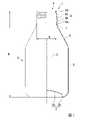
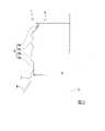
図1、図2および図4、図5は、それぞれ本発明の第1および第2の実施形態において製造されるボトル缶の缶本体1の一部破断側面図を示すものであり、図3および図6は、第1および第2の実施形態におけるボトルネック成形工程においてこれらの缶本体1に成形される有底円筒体11の概略を示す部分断面図である。図1に示すボトル缶は容量が310ml用のものであり、図4に示すボトル缶は容量が410ml用のものである。これら図1ないし図6に示す第1および第2の実施形態における缶本体1および有底円筒体11において、互いに共通する部分には同一の符号を配してある。1, FIG. 2 and FIGS. 4 and 5 show partially broken side views of the
図1および図4に示すように、本実施形態により製造されるボトル缶の缶本体1は、底部2と、この底部2と一体に形成されて底部2の外周縁から上端側(図1および図4において上側)に延びる外周部3とを備えた缶軸Cを中心とする概略多段の有底円筒状をなしている。底部2には、缶軸C方向の内側(缶本体1の上端側)に凹む断面略円弧状のドーム部2aが中央に形成されるとともに、このドーム部2aの外周には缶軸C方向の外側(缶本体1の下端側)に突出する環状凸部2bが缶軸C回りの周方向に連続して形成されている。 As shown in FIGS. 1 and 4, the
また、外周部3には底部2から缶本体1の上端側の開口部4に向けて順に、缶軸Cを中心とした円筒状の胴部5と、上端側に向かうに従い一定の傾斜で漸次縮径する円錐台面状の肩部6と、この肩部6からさらに上端側に向かって延びる筒状の首部7と、首部7の上端から缶本体1の内周側に凹む環状の谷部8a、この谷部8aに対して外周側に張り出す膨出部8b、この膨出部8bの上端側に順に配設されるネジ部8cおよびカール部8dを備えたキャップ取付部8とが形成されている。 Further, the outer
缶本体1の底部2の下端縁(環状凸部2bの下端縁)から外周部3の上端(カール部8dの上端縁)までの缶高さHは、310ml用のボトル缶である第1の実施形態の缶本体1では129.0mm~135.0mm、好ましくは131.6mm~133.6mm、410ml用のボトル缶である第2の実施形態の缶本体1では160.0mm~166.5mm、好ましくは163.0mm~165.0mmとされる。また、缶本体1の外周部3における胴部5の直径は、第1および第2の実施形態のボトル缶ともに64.24mm~68.24mmとされる。 The can height H from the lower end edge of the
このようなボトル缶を製造するには、まずカッピングプレス機によるカッピングプレス工程において、金属板を円板状に打ち抜いて絞り加工を施すことにより深さの浅いカップ状素材を製造する。このカッピングプレス工程においてカップ状素材に成形される金属板は、第1の実施形態では元板厚が0.250mm~0.300mm、第2の実施形態では元板厚が0.270mm~0.320mmのアルミニウム板またはJIS H 4000におけるA3004あるいはA3104のアルミニウム合金板であって、205℃×20分ベーキング後の0.2%耐力が235N/mm2~265N/mm2の範囲のものが用いられる。In order to manufacture such a bottle can, first, in a cupping press process using a cupping press machine, a metal plate is punched into a disk shape and drawn to produce a cup-shaped material having a shallow depth. In the first embodiment, the metal plate formed into the cup-shaped material in this cupping press step has an original plate thickness of 0.250 mm to 0.300 mm, and in the second embodiment, the original plate thickness is 0.270 mm to 0. A 320 mm aluminum plate or an A3004 or A3104 aluminum alloy plate in JIS H 4000 having a 0.2% proof stress in the range of 235 N / mm2 to 265 N / mm2 after baking at 205 ° C. for 20 minutes is used. ..
次に、このカップ状素材にDIプレス機によるDIプレス工程において再絞りおよびしごき加工を施して缶軸C方向に延伸することにより、外周部に上記缶軸Cを中心とした円筒部12が形成されるとともに、底部2には缶本体1と同様のドーム部2aと環状凸部2bが形成された、図3および図6に示すような有底円筒体11を成形する。この有底円筒体11および缶本体1の底部2の厚さは、カッピングプレス工程においてカップ状素材に成形される金属板の元板厚と略等しい。 Next, the cup-shaped material is re-squeezed and ironed in a DI pressing process using a DI press machine and stretched in the can shaft C direction to form a
また、この有底円筒体11の上記円筒部12は、その外径(直径)が缶本体1の胴部5の外径と略等しい一定外径とされる。さらに、この円筒部12の底部2側の部分は厚さ(肉厚)が薄くされた薄肉部であるウォール部13とされるとともに、底部2とは反対の上端側(図3および図6において上側)の部分は、ウォール部13よりも厚さが厚くされた厚肉部であるフランジ部14とされている。ここで、このような厚さの異なるウォール部13とフランジ部14とを円筒部12に形成するには、上述のようにDIプレス機において複数のしごきダイスとの間でしごき加工を行うパンチの外表面のフランジ部14と対応する位置に、肉厚の差を考慮した深さの凹部を形成しておけばよい。 Further, the
これらウォール部13およびフランジ部14においては、その厚さがそれぞれ略一定とされるとともに、ウォール部13とフランジ部14との間では有底円筒体11の上端側に向かうに従い厚さが漸次厚くなるようにされている。ただし、図3および図6では説明のため、これらの厚さは有底円筒体11の高さや外径に対して比率が大きく描かれている。なお、フランジ部14の厚さが一定とされた部分の缶軸C方向の長さは、42mm~60mmの範囲とされるのが望ましく、第1、第2の実施形態の有底円筒体11ではともに約52mmとされている。 The thickness of each of the
そして、これら図3および図6に示す有底円筒体11においては、円筒部12の薄肉部であるウォール部13の厚さt1が0.100mm~0.130mmの範囲とされるとともに、円筒部12のうち厚肉部であるフランジ部14の厚さt2が0.140mm~0.200mmの範囲とされている。さらに、このフランジ部14とウォール部13との間の段差t2-t1は0.090mm以下となるようにされている。なお、この段差t2-t1は0.070mm以下とされるのが望ましく、ただし0.045mm以上であることが望ましい。In the bottomed
このように成形された有底円筒体11は、トリマーによるトリミング工程において円筒部12の上端縁が所定のトリム代で切断されて高さが揃えられてから、第1の洗浄工程において洗浄、乾燥され、次に塗装工程において内外面に塗装が施されて焼き付けられる。さらに、塗装が施された有底円筒体11は、ボトルネッカーによるボトルネック成形工程において、円筒部12のうちフランジ部14の範囲が縮径されて上記肩部6と首部7、および外径(直径)Dが28.7mm~32.7mmの範囲で直径33mmのキャップの裾巻き部(フレア)が巻締め可能なキャップ取付部8の谷部8aが成形される。 The bottomed
次いで、この谷部8aの上端側が拡径されて膨出部8bが形成されるとともに、この膨出部8bよりも上端側にネジ部8cが形成された後に、ネジ部8cより上端側が外周側に折り返されてカールさせられてカール部8dが形成されることにより上記キャップ取付部8が成形され、図1および図3に示したようなボトル缶の缶本体1とされる。なお、膨出部8bの外径は31.1mm~35.1mmの範囲とされ、ネジ部8cの外径は30.4mm~34.4mmの範囲とされる。また、このボトルネック成形工程においても、必要に応じてトリミングを行ってもよい。 Next, the upper end side of the
こうして成形された缶本体1は、第2の洗浄工程によって洗浄、乾燥された後に、検査工程においてピンホールの有無や外面の異物付着、傷、汚れ、印刷不良等が検査されて飲料工場等に搬送され、飲料等の内容物が充填された後に図示されないキャップが取り付けられて封止され、出荷される。なお、缶本体1の上記各成形工程の間や成形工程中には、必要に応じて底部2の環状凸部2bの断面形状を再成形するボトムリフォームが行われてもよい。 The
このような構成のボトル缶の製造方法では、ボトルネック成形工程で缶本体1に成形される有底円筒体11において、円筒部12におけるウォール部13の厚さt1が0.100mm~0.130mmとされるとともに、フランジ部14の厚さt2が0.140mm~0.200mmとされ、さらにフランジ部14とウォール部13との段差t2-t1が0.090mm以下とされているので、上記知見に基づき、後述する実施例で実証されるように有底円筒体11や缶本体1の座屈や変形、トリム代不足、パンチの抜け不良を生じることなく、310ml用および410ml用それぞれのボトル缶において所定の缶高さHの缶本体1を成形することができる。 In the method for manufacturing a bottle can having such a configuration, in the bottomed
従って、有底円筒体11に成形される金属板の元板厚を上述のように薄くしてボトル缶の軽量化を図っても、歩留まりの低下を招くことなく確実かつ効率的なボトル缶の製造を行うことができる。このため、膨大な数のボトル缶が市場に流通している現状において、大幅な省資源化および省エネルギー化を可能とすることができるとともに、ボトル缶のコスト削減を促すこともできる。 Therefore, even if the base plate thickness of the metal plate formed into the bottomed
ここで、上記有底円筒体11において、ウォール部13の厚さt1が0.100mmを下回ると、DIプレス工程において有底円筒体11に座屈や変形を生じるおそれがある。また、有底円筒体11のフランジ部14の厚さt2が0.140mmを下回ると、ボトルネック成形工程において肩部6や首部7、キャップ取付部8を成形する際や、キャッピング工程においてキャップを巻締めして取り付ける際に、缶本体1にやはり座屈や変形、割れなどを生じるおそれがある。なお、フランジ部14の厚さが一定とされた部分の缶軸C方向の長さが42mmを下回った場合にも、ボトルネック成形工程において肩部6を成形する際やキャッピング工程において肩部6に座屈や変形を生じるおそれがある。 Here, in the bottomed
さらに、ウォール部13の厚さt1が0.130mmを上回ったり、フランジ部14の厚さt2が0.200mmを上回ったりすると、上述のような薄い元板厚の金属板から成形される有底円筒体11では、DIプレス工程において必要な高さを得ることができなくなってトリム代不足を生じ、ボトルネック成形工程に送っても所定の缶高さHの缶本体1を成形することができなくなってしまう。また、フランジ部14の厚さt2が0.200mmを上回った場合には、トリム代不足が生じなくてもボトルネック成形工程における成形荷重が増大するおそれもある。Further, when the thickness t1 of the
さらにまた、フランジ部14とウォール部13との段差t2-t1が0.090mmを上回ると、DIプレス工程において上述のような外表面に凹部を設けたパンチを用いた場合にパンチの抜け不良が発生してしまい、DIプレス機を停止して抜け損ねた有底円筒体11をパンチから取り外さなければならなくなってボトル缶の製造効率や歩留まりが低下してしまう。さらに、段差t2-t1が大きすぎると、DIプレス工程やボトルネック成形工程において段差の部分に成形荷重による応力が集中して有底円筒体11や缶本体1が座屈したり変形したりするおそれもある。 Furthermore, if the step t2-t1 between the
しかも、直径33mmのキャップに対応したキャップ取付部8の下端の膨出部8bと肩部6との間の最小径部である谷部8aの外径(直径)Dが28.7mm~32.7mmの範囲である本実施形態のボトル缶の製造方法においては、直径38mmのキャップに対応したボトル缶の製造方法に比べ、特にキャッピング工程においてキャップ取付部8の変形や座屈を一層確実に防止することができる。すなわち、キャッピング工程において、キャップ下端部の裾巻き部をキャッピング装置の裾巻きロールにより、首部7とキャップ取付部8の膨出部8bとの間の谷部8aに巻締める際に谷部8aが受ける径方向内側へ向けた押圧力Pと、これに応じた谷部8aの変形量(半径の変化量)△Rは、以下の式(1)で表すことができる。 Moreover, the outer diameter (diameter) D of the
△R=R2/(t×E)×P …(1)ΔR = R2 / (t × E) × P… (1)
なお、上記式(1)のうち、Pは外圧(裾巻きロールから谷部8aが径方向内側へ向けて受ける圧力)、Rは谷部8aの外径(ただし、半径)、tは谷部8aにおける缶本体1の厚さ(肉厚)、Eは缶本体1の金属材料のヤング率である。このため、上記式(1)より、外圧P、厚さtおよびヤング率Eが一定の場合、谷部8aの変形量△Rは、谷部8aの半径Rの二乗に比例することが分かる。従って、谷部8aの半径Rが小さくなれば、谷部8aの変形量△Rも、半径Rの二乗に比例して小さくなる(なお、実際には半径Rが変化すると厚さtも僅かに変化するが、微小量であるためここでは考慮しないこととする。)。 In the above formula (1), P is the external pressure (pressure received by the
従って、直径38mmのキャップに対応した谷部の外径が約35.4mmのボトル缶よりも、直径33mmのキャップに対応した谷部8aの外径Dが約30.7mmの本実施形態のボトル缶の方が、裾巻きロールから受ける押圧力が従来と同じ場合に、上記式(1)によれば谷部8aの変形量△Rは約25%低減され、キャップ取付部8の変形を確実に防止することができる。このため、上述のように缶本体1に成形される金属板の元板厚の薄肉化を図った場合であっても、キャッピング時の成形荷重(軸荷重や横荷重)によってキャップ取付部8が変形することを確実に防止できる。 Therefore, the bottle of the present embodiment having the outer diameter D of the
なお、本実施形態の有底円筒体11においては、ウォール部13の厚さt1が上述のように略一定とされているが、ウォール部13のフランジ部14側に厚さt1よりも厚く、フランジ部14の厚さt2よりは薄い2段目のウォール部を形成するなどして、ウォール部13を複数段に成形してもよい。このような場合のウォール部13の厚さt1は、底部2側の最も薄肉となる最薄部の厚さとすればよい。 In the bottomed
次に、本発明の実施例を挙げて、本発明の効果について実証する。本実施例では、図1ないし図3および図4ないし図6に示した第1、第2の実施形態に基づいて、金属板の元板厚、有底円筒体11の円筒部12のフランジ部14の厚さt2、ウォール部13の厚さt1および段差t2-t1を種々に変化させた23種類の有底円筒体11をDIプレス工程において1000個ずつ成形してDIプレス機による成形性(DI成形性)を確認するとともに、このうち100個ずつの有底円筒体11をボトルネック成形工程において缶本体1に成形して、その際のボトルネック成形性(BN成形性)を確認し、さらにこのうち10個の缶についてキャッピング工程において実際に直径33mmのキャップをキャッピングした後に開栓してからキャップを再びキャップ取付部にねじ込んでリシールする際のリシールトルクを測定することによりキャッピング性を確認した。これらを、第1の実施形態に基づくものについては実施例1~23として表1に、また第2の実施形態に基づくものについては実施例31~52として表3に、それぞれ成形された缶本体1の質量とともに示す。 Next, an example of the present invention will be given to demonstrate the effect of the present invention. In this embodiment, the original plate thickness of the metal plate and the flange portion of the
また、これら実施例1~23および実施例31~52に対する比較例として、元板厚やフランジ部14の厚さt2、ウォール部13の厚さt1および段差t2-t1を種々に変化させた、実施例1~23および実施例31~52に対してそれぞれ15種類の有底円筒体11を、同様にDIプレス工程において1000個ずつ成形してDI成形性を確認するとともに、これらの有底円筒体11のうちDIプレス成形によって所定の高さの有底円筒体11を成形可能であったもの100個をボトルネック成形工程において缶本体1に成形して、その際のBN成形性を確認し、さらにそのうち10個をキャッピング工程においてキャッピングした後に開栓してからキャップを再びキャップ取付部にねじ込んでリシールする際のリシールトルクを測定することによりキャッピング性を確認した。これらを、実施例1~23に対しては比較例1~15として表2に、また実施例31~52に対しては比較例31~45として表4に、DIプレス成形およびボトルネック成形可能であったものの成形された缶本体1の質量とともに示す。 Further, as comparative examples with respect to Examples 1 to 23 and Examples 31 to 52, the original plate thickness, the thickness t2 of the
なお、実施例1~23および比較例1~15において、ボトル缶に成形できたものの缶高さは第1の実施形態の範囲内で平均132.6mm、胴部5の直径は同じく第1の実施形態の範囲内で平均66.24mmであった。また、実施例31~52および比較例31~45においては、ボトル缶に成形できたものの缶高さは第2の実施形態の範囲内で平均164.0mm、胴部5の直径は同じく第2の実施形態の範囲内で平均66.24mmであった。さらに、これら実施例1~23および比較例1~15と、実施例31~52および比較例31~45においては、キャップ取付部8の谷部8aの外径(直径)Dは平均で30.7mmであり、ボトル缶の缶本体1に成形される前の有底円筒体11においてフランジ部14の厚さが一定とされた部分の缶軸C方向の長さは、いずれも約52mmであった。 In Examples 1 to 23 and Comparative Examples 1 to 15, the can height of the bottle cans was 132.6 mm on average within the range of the first embodiment, and the diameter of the
ここで、DI成形性の評価は、成形しようとした1000個の有底円筒体11のうちすべてが座屈や変形、胴切れ、パンチの抜け不良等を生じることなくDIプレス成形できていた場合を丸印とし、1000個中1個までに座屈や変形、胴切れ等が生じてDIプレス機が1回停止した場合を三角印とし、DIプレス機が2回以上停止した場合をバツ印とした。 Here, the evaluation of DI formability is performed when all of the 1000 bottomed
また、BN成形性の評価は、DIプレス工程において所定の寸法通りに成形できた有底円筒体11のうち100個に、ボトルネック成形工程において肩部6、首部7と、谷部8a、膨出部8b、ネジ部8cおよびカール部8dからなるキャップ取付部8を成形し、これらを目視で観察して、すべてが座屈等を生じることなく所定の寸法通りにボトルネック成形できた場合を丸印とし、1個までに座屈等が生じていた場合を三角印、2個以上に座屈や変形等が生じていた場合をバツ印とした。 In addition, the evaluation of BN formability was performed on 100 of the bottomed
さらに、ボトルネック成形工程において座屈等を生じることなく成形された10個の缶本体1に、キャッピング工程においてキャップ取付部8に天板部と周壁部を有する直径33mmの有底筒状のキャップ成形体を被せて、株式会社CSIジャパン製のキャッパーにより、850Nの缶軸C方向の垂直荷重(トッププレッシャー)を加えることによって天板部外周を絞り加工して段部を成形するとともに、ロールセット径39.0mm、スレッドローラートルク3.6N・mでスレッドローラーにより周壁部の天板部側に缶軸Cに対する径方向内周側に荷重を与えてネジ部8cに倣うように雌ネジ部を成形し、さらに同じくロールセット径39.0mm、スカートローラートルク2.8N・mでスカートローラーにより周壁部の天板部とは反対側の裾巻き部に缶軸Cに対する径方向内周側に荷重を与えて膨出部8b下端の谷部8aに巻き締め(裾締め)した。なお、これらのキャッピング条件は、現行の元板厚が約0.345mmのアルミニウム合金板材から製造される310ml用のアルミニウム合金製ボトル缶へのキャッピング条件や、同じく現行の元板厚が約0.400mmのアルミニウム合金板材から製造される410ml用のアルミニウム合金製ボトル缶へのキャッピング条件を見直したものである。 Further, 10 can
ここで、スレッドローラートルクおよびスカートローラートルクとは、それぞれスレッドローラーがキャップ成形体に雌ネジ部を成形する際に周壁部に与える荷重の大きさ、およびスカートローラーがキャップ成形体の裾巻き部を膨出部8b下端の谷部8aに巻き締める際に裾巻き部に与える荷重の大きさの代用値であり、すなわち各ローラーを缶軸Cに対する径方向内周側に押し付けるための駆動アームのトルク値のことを示す。また、ロールセット径とは、これらのローラーが缶軸Cから最も離れた初期の設定位置にあるときの向かい合うローラーの径方向内周側の縁部同士の距離(缶軸Cを中心として対向するローラーの内周縁に内接する円の直径)であり、このロールセット径とスレッドローラートルクおよびスカートローラートルクから雌ネジ部成形時と裾巻き時の各ローラーの先端荷重を計算することができる。 Here, the thread roller torque and the skirt roller torque are the magnitude of the load applied to the peripheral wall portion when the thread roller forms the female thread portion on the cap molded body, respectively, and the skirt roller determines the hem winding portion of the cap molded body. It is a substitute value of the magnitude of the load applied to the hem winding portion when winding around the
そして、キャッピング性については、こうしてキャッピング工程においてキャップ成形体から成形されてキャップ取付部8に取り付けられたキャップを一旦開栓してから再びキャップ取付部8にねじ込んでリシールする際のリシールトルクを測定し、このリシールトルクが20N・cm以上となるものが0缶であった場合を丸印、1缶であった場合を三角印、2缶以上であった場合をバツ印とした。キャッピング工程における成形荷重によってキャップ取付部8に座屈や変形が生じると、缶本体1のネジ部8cとキャップの雌ネジ部との摩擦抵抗が増大し、リシールトルクも増大することになる。 As for the capping property, the reseal torque when the cap molded from the cap molded body and attached to the


このうち、まず表2の比較例1および表4の比較例31においては、DI成形性、BN成形性、キャッピング性ともに良好ではあったものの、元板厚が厚いため実施例1~23および実施例31~52に比べて質量が大きく、十分な軽量化が図られてはいなかった。また、比較例2~5および比較例32~35では、段差t2-t1が大きすぎたためにパンチの抜け不良が発生し、DIプレス機が頻繁に停止して安定したDIプレス成形を行うことができなかった。さらに、このうち比較例4、5と比較例6~10、および比較例34、35と比較例36~40では、ウォール部13の厚さt1が薄すぎたため、ボトルネック成形工程においてウォール部13に座屈を生じたものが多かった。さらに、比較例11~15および比較例41~45では、フランジ部14の厚さt2が薄かったため、キャップ取付部8に座屈や変形が生じたものが多く、リシールトルクが増大してキャッピング性が損なわれる結果となった。 Of these, in Comparative Example 1 of Table 2 and Comparative Example 31 of Table 4, although the DI moldability, the BN moldability, and the capping property were all good, the original plate thickness was thick, so that Examples 1 to 23 and the examples were carried out. The mass was larger than that of Examples 31 to 52, and the weight was not sufficiently reduced. Further, in Comparative Examples 2 to 5 and Comparative Examples 32 to 35, the step t2-t1 was too large, so that a punch pull-out defect occurred, and the DI press machine was frequently stopped to perform stable DI press molding. could not. Further, in Comparative Examples 4 and 5 and Comparative Examples 6 to 10, and Comparative Examples 34 and 35 and Comparative Examples 36 to 40, the thickness t1 of the
このような比較例1~15および比較例31~45に対して、実施例1~23および実施例31~52では、DIプレス工程においては、すべてで座屈や変形、パンチの抜け不良を生じることなく、1000個すべての有底円筒体11を所定の寸法に成形することができた。また、BN成形性についても、ウォール部13の厚さt1が0.100mmであった実施例7、11、15、19および実施例36、40、44、48において100個中1個に座屈が認められたものの、これら以外には座屈を確認したものはなかった。さらに、キャッピング性についても、フランジ部14の厚さt2が0.140mmである実施例20~23および実施例49~52において、リシールトルクが20N・cm以上となった缶本体1は1缶だけであり、これら以外ではリシールトルクの増大は認められなかった。 In contrast to Comparative Examples 1 to 15 and Comparative Examples 31 to 45, in Examples 1 to 23 and Examples 31 to 52, buckling, deformation, and punch removal failure occur in all of the DI pressing steps. All 1000 bottomed
そして、310ml用のボトル缶である実施例1~23では缶本体1の質量が従来の17.5gに対して16.0g~13.5g、410ml用のボトル缶である実施例31~52でも缶本体1の質量が従来の21.0gに対して19.0g~16.5gと、いずれも1.5g以上の軽量化を可能とすることができた。これは、1つ1つのボトル缶では微々たるものであるが、膨大な数のボトル缶が市場に流通することを考慮すると、大幅な省資源化、省エネルギー化が図られることを意味する。なお、質量はボトルネック成形できた缶本体1の平均値である。 Further, in Examples 1 to 23 which are bottle cans for 310 ml, the mass of the
1 缶本体
2 底部
2a ドーム部
2b 環状凸部
3 外周部
4 開口部
5 胴部
6 肩部
7 首部
8 キャップ取付部
8a 谷部
8b 膨出部
8c ネジ部
8d カール部
11 有底円筒体
12 円筒部
13 ウォール部
14 フランジ部
C 缶軸
D 谷部8aの外径(直径)
H 缶高さ
t1 ウォール部13の厚さ
t2 フランジ部14の厚さ1 Can
H Can height t1 Thickness of
Claims (2)
Translated fromJapaneseこのカップ状素材にDIプレス工程において再絞りおよびしごき加工を施して、底部と円筒部とを有し、上記円筒部の底部側の薄肉部であるウォール部の厚さが0.100mm~0.130mm、上記円筒部の底部とは反対側の厚肉部であるフランジ部の厚さが0.140mm~0.200mm、上記フランジ部の厚さが一定とされた部分の缶軸方向の長さが42mm~60mm、上記フランジ部と上記ウォール部との段差が0.090mm以下の有底円筒体を成形し、
この有底円筒体の上記フランジ部にボトルネック成形工程において、円筒状の胴部から上記底部とは反対側に向かうに従い縮径する肩部と、下端に外周側に膨出する膨出部を有するキャップ取付部とを成形することにより、上記膨出部と上記肩部との間の最小径部である谷部の外径が28.7mm~32.7mm、上記底部から上記キャップ取付部の上端までの缶高さが129.0mm~135.0mm、上記胴部の直径が64.24mm~68.24mm、質量が13.5g~16.0gの缶本体を有するボトル缶を製造することを特徴とするボトル缶の製造方法。A cup-shaped material is formed from a metal plate having an original plate thickness of 0.250 mm to 0.300 mmand a 0.2% proof stress of 235 N / mm2to 265 N / mm2 by drawing in a cupping press process.
This cup-shaped material is re-squeezed and ironed in the DI press process to have a bottom and a cylindrical portion, and the thickness of the wall portion, which is a thin-walled portion on the bottom side of the cylindrical portion, is 0.100 mm to 0. 130 mm, the thickness of the flange portion, which is a thick portion on the opposite side of the bottom of the cylindrical portion, is 0.140 mm to 0.200 mm,and the length of the portion where the thickness of the flange portion is constant in the can axis direction. A bottomed cylinder having a diameterof 42 mm to 60 mm and a step difference between the flange portion and the wall portion of 0.090 mm or less is formed.
In the bottleneck forming step on the flange portion of the bottomed cylinder, a shoulder portion whose diameter is reduced from the cylindrical body portion toward the side opposite to the bottom portion and a bulging portion bulging toward the outer peripheral side at the lower end are provided. By molding the cap mounting portion to have, the outer diameter of the valley portion, which is the minimum diameter portion between the bulging portion and the shoulder portion, is 28.7 mm to 32.7 mm, and the cap mounting portion is formed from the bottom portion. To manufacture a bottle can having a can body having a can height of 129.0 mm to 135.0 mm to the upper end, a body diameter of 64.24 mm to 68.24 mm, and a mass of 13.5 g to 16.0 g . A characteristic method for manufacturing bottle cans.
このカップ状素材にDIプレス工程において再絞りおよびしごき加工を施して、底部と円筒部とを有し、上記円筒部の底部側の薄肉部であるウォール部の厚さが0.100mm~0.130mm、上記円筒部の底部とは反対側の厚肉部であるフランジ部の厚さが0.140mm~0.200mm、上記フランジ部の厚さが一定とされた部分の缶軸方向の長さが42mm~60mm、上記フランジ部と上記ウォール部との段差が0.090mm以下の有底円筒体を成形し、
この有底円筒体の上記フランジ部にボトルネック成形工程において、円筒状の胴部から上記底部とは反対側に向かうに従い縮径する肩部と、下端に外周側に膨出する膨出部を有するキャップ取付部とを成形することにより、上記膨出部と上記肩部との間の最小径部である谷部の外径が28.7mm~32.7mm、上記底部から上記キャップ取付部の上端までの缶高さが160.0mm~166.5mm、上記胴部の直径が64.24mm~68.24mm、質量が16.5g~19.0gの缶本体を有するボトル缶を製造することを特徴とするボトル缶の製造方法。A cup-shaped material is formed from a metal plate having an original plate thicknessof 0.270 mm to 0.320 mm and a 0.2% proof stress of 235 N / mm2to 265 N / mm2 by drawing in a cupping press process.
This cup-shaped material is re-squeezed and ironed in the DI press process to have a bottom and a cylindrical portion, and the thickness of the wall portion, which is a thin-walled portion on the bottom side of the cylindrical portion, is 0.100 mm to 0. 130 mm, the thickness of the flange portion, which is a thick portion on the opposite side of the bottom of the cylindrical portion, is 0.140 mm to 0.200 mm,and the length of the portion where the thickness of the flange portion is constant in the can axis direction. A bottomed cylinder having a diameterof 42 mm to 60 mm and a step difference between the flange portion and the wall portion of 0.090 mm or less is formed.
In the bottleneck forming step on the flange portion of the bottomed cylinder, a shoulder portion whose diameter is reduced from the cylindrical body portion toward the side opposite to the bottom portion and a bulging portion bulging toward the outer peripheral side at the lower end are provided. By molding the cap mounting portion to have, the outer diameter of the valley portion, which is the minimum diameter portion between the bulging portion and the shoulder portion, is 28.7 mm to 32.7 mm, and the cap mounting portion is formed from the bottom portion. To manufacture a bottle can having a can body having a can height of 160.0 mm to 166.5 mm to the upper end, a body diameter of 64.24 mm to 68.24 mm, and a mass of 16.5 g to 19.0 g . A characteristic method for manufacturing bottle cans.
Priority Applications (1)
| Application Number | Priority Date | Filing Date | Title |
|---|---|---|---|
| JP2017245160AJP7072380B2 (en) | 2017-12-21 | 2017-12-21 | How to make a bottle can |
Applications Claiming Priority (1)
| Application Number | Priority Date | Filing Date | Title |
|---|---|---|---|
| JP2017245160AJP7072380B2 (en) | 2017-12-21 | 2017-12-21 | How to make a bottle can |
Publications (2)
| Publication Number | Publication Date |
|---|---|
| JP2019112075A JP2019112075A (en) | 2019-07-11 |
| JP7072380B2true JP7072380B2 (en) | 2022-05-20 |
Family
ID=67222205
Family Applications (1)
| Application Number | Title | Priority Date | Filing Date |
|---|---|---|---|
| JP2017245160AActiveJP7072380B2 (en) | 2017-12-21 | 2017-12-21 | How to make a bottle can |
Country Status (1)
| Country | Link |
|---|---|
| JP (1) | JP7072380B2 (en) |
Citations (5)
| Publication number | Priority date | Publication date | Assignee | Title |
|---|---|---|---|---|
| JP2004035036A (en) | 2002-07-02 | 2004-02-05 | Mitsubishi Materials Corp | Metallic bottle can |
| JP2004083128A (en) | 2001-12-28 | 2004-03-18 | Mitsubishi Materials Corp | Bottle can body and bottle |
| JP2004359289A (en) | 2003-06-04 | 2004-12-24 | Mitsubishi Materials Corp | Cap |
| JP2006062755A (en) | 1994-11-22 | 2006-03-09 | Alcoa Inc | Threaded aluminum can and manufacturing method thereof |
| JP2007153376A (en) | 2005-12-02 | 2007-06-21 | Daiwa Can Co Ltd | Aluminum alloy can with small capacity screw |
- 2017
- 2017-12-21JPJP2017245160Apatent/JP7072380B2/enactiveActive
Patent Citations (5)
| Publication number | Priority date | Publication date | Assignee | Title |
|---|---|---|---|---|
| JP2006062755A (en) | 1994-11-22 | 2006-03-09 | Alcoa Inc | Threaded aluminum can and manufacturing method thereof |
| JP2004083128A (en) | 2001-12-28 | 2004-03-18 | Mitsubishi Materials Corp | Bottle can body and bottle |
| JP2004035036A (en) | 2002-07-02 | 2004-02-05 | Mitsubishi Materials Corp | Metallic bottle can |
| JP2004359289A (en) | 2003-06-04 | 2004-12-24 | Mitsubishi Materials Corp | Cap |
| JP2007153376A (en) | 2005-12-02 | 2007-06-21 | Daiwa Can Co Ltd | Aluminum alloy can with small capacity screw |
Also Published As
| Publication number | Publication date |
|---|---|
| JP2019112075A (en) | 2019-07-11 |
Similar Documents
| Publication | Publication Date | Title |
|---|---|---|
| US6499622B1 (en) | Can lid closure and method of joining a can lid closure to a can body | |
| EP2162364B1 (en) | Low gauge crown cap | |
| US10961009B2 (en) | Threaded metal container | |
| CN1041188C (en) | container end cap | |
| JP7206046B2 (en) | Bottle can and method for manufacturing bottle can | |
| JP2015214343A (en) | can | |
| JP6877943B2 (en) | How to make bottle cans | |
| JP7072380B2 (en) | How to make a bottle can | |
| JP2023143990A (en) | can body | |
| JP2018131261A (en) | Manufacturing method for bottle can | |
| JP2019111554A (en) | Method for manufacturing bottle can | |
| US12097991B2 (en) | Bottle can, manufacturing method of bottle can, and design method of bottle can | |
| JP6546946B2 (en) | Bottle with cap | |
| JP2018154407A (en) | Production method of bottle can | |
| JP2018104095A (en) | Bottle can | |
| JP7220983B2 (en) | bottle can, bottle can with cap | |
| JP6807702B2 (en) | How to make bottle cans | |
| JP2018103254A (en) | Bottle can, capped bottle can, and manufacturing method for the same | |
| JP7262344B2 (en) | bottle can | |
| JP7484148B2 (en) | Bottle can and its manufacturing method | |
| JP6576047B2 (en) | Can lid | |
| JP7293715B2 (en) | Bottle can manufacturing method | |
| JP2019131265A (en) | Bottle can and method of producing thereof | |
| JP7528430B2 (en) | Bottle can and its manufacturing method | |
| EP3919400A1 (en) | Bottle can, production method for bottle cans, and design method for bottle cans |
Legal Events
| Date | Code | Title | Description |
|---|---|---|---|
| A621 | Written request for application examination | Free format text:JAPANESE INTERMEDIATE CODE: A621 Effective date:20200910 | |
| A977 | Report on retrieval | Free format text:JAPANESE INTERMEDIATE CODE: A971007 Effective date:20210720 | |
| A131 | Notification of reasons for refusal | Free format text:JAPANESE INTERMEDIATE CODE: A131 Effective date:20210803 | |
| A521 | Request for written amendment filed | Free format text:JAPANESE INTERMEDIATE CODE: A523 Effective date:20211001 | |
| A02 | Decision of refusal | Free format text:JAPANESE INTERMEDIATE CODE: A02 Effective date:20211109 | |
| A521 | Request for written amendment filed | Free format text:JAPANESE INTERMEDIATE CODE: A523 Effective date:20220209 | |
| C60 | Trial request (containing other claim documents, opposition documents) | Free format text:JAPANESE INTERMEDIATE CODE: C60 Effective date:20220209 | |
| A911 | Transfer to examiner for re-examination before appeal (zenchi) | Free format text:JAPANESE INTERMEDIATE CODE: A911 Effective date:20220221 | |
| C21 | Notice of transfer of a case for reconsideration by examiners before appeal proceedings | Free format text:JAPANESE INTERMEDIATE CODE: C21 Effective date:20220222 | |
| TRDD | Decision of grant or rejection written | ||
| A01 | Written decision to grant a patent or to grant a registration (utility model) | Free format text:JAPANESE INTERMEDIATE CODE: A01 Effective date:20220412 | |
| A61 | First payment of annual fees (during grant procedure) | Free format text:JAPANESE INTERMEDIATE CODE: A61 Effective date:20220510 | |
| R150 | Certificate of patent or registration of utility model | Ref document number:7072380 Country of ref document:JP Free format text:JAPANESE INTERMEDIATE CODE: R150 | |
| S533 | Written request for registration of change of name | Free format text:JAPANESE INTERMEDIATE CODE: R313533 | |
| R350 | Written notification of registration of transfer | Free format text:JAPANESE INTERMEDIATE CODE: R350 | |
| R250 | Receipt of annual fees | Free format text:JAPANESE INTERMEDIATE CODE: R250 |