JP7070484B2 - Calibration methods and programs for wearable devices, electronic watches, and magnetic sensors - Google Patents
Calibration methods and programs for wearable devices, electronic watches, and magnetic sensorsDownload PDFInfo
- Publication number
- JP7070484B2 JP7070484B2JP2019052244AJP2019052244AJP7070484B2JP 7070484 B2JP7070484 B2JP 7070484B2JP 2019052244 AJP2019052244 AJP 2019052244AJP 2019052244 AJP2019052244 AJP 2019052244AJP 7070484 B2JP7070484 B2JP 7070484B2
- Authority
- JP
- Japan
- Prior art keywords
- mode
- calibration
- magnetic sensor
- electronic clock
- time
- Prior art date
- Legal status (The legal status is an assumption and is not a legal conclusion. Google has not performed a legal analysis and makes no representation as to the accuracy of the status listed.)
- Active
Links
Images


Classifications
- G—PHYSICS
- G01—MEASURING; TESTING
- G01R—MEASURING ELECTRIC VARIABLES; MEASURING MAGNETIC VARIABLES
- G01R33/00—Arrangements or instruments for measuring magnetic variables
- G01R33/02—Measuring direction or magnitude of magnetic fields or magnetic flux
- G—PHYSICS
- G01—MEASURING; TESTING
- G01R—MEASURING ELECTRIC VARIABLES; MEASURING MAGNETIC VARIABLES
- G01R33/00—Arrangements or instruments for measuring magnetic variables
- G01R33/0017—Means for compensating offset magnetic fields or the magnetic flux to be measured; Means for generating calibration magnetic fields
- G—PHYSICS
- G06—COMPUTING OR CALCULATING; COUNTING
- G06F—ELECTRIC DIGITAL DATA PROCESSING
- G06F1/00—Details not covered by groups G06F3/00 - G06F13/00 and G06F21/00
- G06F1/16—Constructional details or arrangements
- G06F1/1613—Constructional details or arrangements for portable computers
- G06F1/163—Wearable computers, e.g. on a belt
- G—PHYSICS
- G01—MEASURING; TESTING
- G01C—MEASURING DISTANCES, LEVELS OR BEARINGS; SURVEYING; NAVIGATION; GYROSCOPIC INSTRUMENTS; PHOTOGRAMMETRY OR VIDEOGRAMMETRY
- G01C17/00—Compasses; Devices for ascertaining true or magnetic north for navigation or surveying purposes
- G01C17/38—Testing, calibrating, or compensating of compasses
- G—PHYSICS
- G01—MEASURING; TESTING
- G01D—MEASURING NOT SPECIALLY ADAPTED FOR A SPECIFIC VARIABLE; ARRANGEMENTS FOR MEASURING TWO OR MORE VARIABLES NOT COVERED IN A SINGLE OTHER SUBCLASS; TARIFF METERING APPARATUS; MEASURING OR TESTING NOT OTHERWISE PROVIDED FOR
- G01D21/00—Measuring or testing not otherwise provided for
- G01D21/02—Measuring two or more variables by means not covered by a single other subclass
- G—PHYSICS
- G01—MEASURING; TESTING
- G01R—MEASURING ELECTRIC VARIABLES; MEASURING MAGNETIC VARIABLES
- G01R33/00—Arrangements or instruments for measuring magnetic variables
- G01R33/0023—Electronic aspects, e.g. circuits for stimulation, evaluation, control; Treating the measured signals; calibration
- G01R33/0035—Calibration of single magnetic sensors, e.g. integrated calibration
- G—PHYSICS
- G04—HOROLOGY
- G04B—MECHANICALLY-DRIVEN CLOCKS OR WATCHES; MECHANICAL PARTS OF CLOCKS OR WATCHES IN GENERAL; TIME PIECES USING THE POSITION OF THE SUN, MOON OR STARS
- G04B47/00—Time-pieces combined with other articles which do not interfere with the running or the time-keeping of the time-piece
- G04B47/06—Time-pieces combined with other articles which do not interfere with the running or the time-keeping of the time-piece with attached measuring instruments, e.g. pedometer, barometer, thermometer or compass
- G—PHYSICS
- G04—HOROLOGY
- G04G—ELECTRONIC TIME-PIECES
- G04G19/00—Electric power supply circuits specially adapted for use in electronic time-pieces
- G04G19/12—Arrangements for reducing power consumption during storage
- G—PHYSICS
- G04—HOROLOGY
- G04G—ELECTRONIC TIME-PIECES
- G04G21/00—Input or output devices integrated in time-pieces
- G04G21/02—Detectors of external physical values, e.g. temperature
- G—PHYSICS
- G04—HOROLOGY
- G04G—ELECTRONIC TIME-PIECES
- G04G5/00—Setting, i.e. correcting or changing, the time-indication
- G—PHYSICS
- G04—HOROLOGY
- G04G—ELECTRONIC TIME-PIECES
- G04G99/00—Subject matter not provided for in other groups of this subclass
- G04G99/006—Electronic time-pieces using a microcomputer, e.g. for multi-function clocks
Landscapes
- Physics & Mathematics (AREA)
- General Physics & Mathematics (AREA)
- Engineering & Computer Science (AREA)
- Computer Hardware Design (AREA)
- Theoretical Computer Science (AREA)
- Condensed Matter Physics & Semiconductors (AREA)
- General Engineering & Computer Science (AREA)
- Human Computer Interaction (AREA)
- Radar, Positioning & Navigation (AREA)
- Remote Sensing (AREA)
- Power Engineering (AREA)
- Electric Clocks (AREA)
- Testing Or Calibration Of Command Recording Devices (AREA)
- Electromechanical Clocks (AREA)
Description
Translated fromJapanese本発明は、ウェアラブル機器、電子時計、磁気センサのキャリブレーション方法及びプログラムに関する。 The present invention relates to a wearable device, an electronic watch, a calibration method and a program of a magnetic sensor.
従来から、磁気センサを備えることにより、地球の磁場を計測して電子コンパスとして利用可能な電子機器が存在している。磁気センサで地球の磁場を計測する際、近傍に磁石や帯磁した物体が存在すると、それらによる磁場と地球の磁場とが合成された磁場が計測される。つまり、本来の地球の磁場に近傍の磁場の影響によるオフセット磁場が加わったものが計測される。したがって、正確な地球の磁場を求めるには、このオフセット磁場の大きさを同定して、磁気センサの計測値から当該オフセット値に応じた補正を行うことにより、磁気センサのキャリブレーションを行う必要がある。 Conventionally, there are electronic devices that can be used as an electronic compass by measuring the magnetic field of the earth by providing a magnetic sensor. When measuring the magnetic field of the earth with a magnetic sensor, if a magnet or a magnetized object exists in the vicinity, the magnetic field obtained by combining the magnetic field of the magnet and the magnetic field of the earth is measured. That is, the original magnetic field of the earth plus an offset magnetic field due to the influence of a nearby magnetic field is measured. Therefore, in order to obtain an accurate magnetic field of the earth, it is necessary to calibrate the magnetic sensor by identifying the magnitude of this offset magnetic field and making corrections according to the offset value from the measured values of the magnetic sensor. be.
従来、磁気センサのキャリブレーションを行うには、キャリブレーションが成功するまで、ユーザが所定の動作(磁気センサを様々な方向に向けたり移動させたりする動作)をしなければならず、ユーザにかなり負担をかけることになっていた。これに対し、特許文献1には、着信時のバイブレータ動作をトリガーに磁気センサのキャリブレーションを行うことで、バイブレータ動作により携帯端末装置が回転することを利用して、自動的に磁気センサのキャリブレーションができる技術が記載されている。 Conventionally, in order to calibrate a magnetic sensor, the user has to perform a predetermined action (movement of pointing or moving the magnetic sensor in various directions) until the calibration is successful, which is quite a problem for the user. It was supposed to be a burden. On the other hand, in Patent Document 1, by calibrating the magnetic sensor triggered by the vibrator operation at the time of incoming call, the magnetic sensor is automatically calibrated by utilizing the fact that the mobile terminal device rotates due to the vibrator operation. The technology that can be used is described.
しかしながら、特許文献1に記載されている技術では、携帯端末装置の回転動作が継続して行われなかった等の場合に、必要なデータが取得できず、キャリブレーションが失敗してしまう場合があった。そういった場合に、キャリブレーションの動作が無駄になってしまうため、消費電力の観点で問題があった。 However, in the technique described in Patent Document 1, when the rotation operation of the mobile terminal device is not continuously performed, necessary data may not be acquired and calibration may fail. rice field. In such a case, the calibration operation is wasted, which causes a problem in terms of power consumption.
本発明は、上記問題を解決するためになされたものであり、自動キャリブレーションの失敗による消費電力を抑えることができるウェアラブル機器、電子時計、磁気センサのキャリブレーション方法及びプログラムを提供することを目的とする。 The present invention has been made to solve the above problems, and an object of the present invention is to provide a wearable device, an electronic watch, a magnetic sensor calibration method and a program capable of suppressing power consumption due to a failure of automatic calibration. And.
上記目的を達成するため、本発明のウェアラブル機器は、
磁気センサを備えているとともに、非デフォルトモードのときに無操作状態が一定時間続いた場合にデフォルトモードに遷移するウェアラブル機器であって、
前記磁気センサのキャリブレーションを行うキャリブレーション手段と、
現在実行中の機能モードが前記非デフォルトモードと前記デフォルトモードとのうちの何れであるのかを判別する判別手段と、
前記ウェアラブル機器を装着したユーザの運動状態として歩行状態を検知する運動状態検知手段と、
を備え、
前記キャリブレーション手段は、
前記運動状態検知手段によって所定の時間以上継続して前記歩行状態を検知した場合であって前記判別手段により現在実行中の機能モードが前記デフォルトモードと判別された場合に、前記磁気センサのキャリブレーションを行い、
前記運動状態検知手段による前記歩行状態の検知が前記所定の時間だけ継続するまでの間、又は、前記判別手段により現在実行中の機能モードが前記非デフォルトモードと判別された場合には、前記磁気センサのキャリブレーションを行わない。In order to achieve the above object, the wearable device of the present invention is used.
It is a wearable device equipped with a magnetic sensor and transitions to the default mode when no operation continues for a certain period of time in the non-default mode .
Calibration means for calibrating the magnetic sensor and
A discriminating means for determining whether thecurrently executing functional modeis the non-default mode or the default mode, and
An exercise statedetecting meansfor detecting a walking state as an exercise state of a user wearing the wearable device, and
Equipped with
The calibration means is
Calibration of the magnetic sensor when the walking state is continuously detected by the motion statedetecting meansfor a predetermined time or longer andthe function mode currently being executed is determined by the discriminating means tobe the default mode . And
Until the detection of the walking state by the motion statedetecting meanscontinues for the predetermined time , or whenthe function mode currently being executed is determined by the discriminating means to be the non-default mode,the magnetism Do not calibrate the sensor.
本発明によれば、自動キャリブレーションの失敗による消費電力を抑えることができる。 According to the present invention, power consumption due to failure of automatic calibration can be suppressed.
以下、本発明の実施形態について、図面を参照して説明する。なお、図中同一又は相当部分には同一符号を付す。 Hereinafter, embodiments of the present invention will be described with reference to the drawings. The same or corresponding parts in the figure are designated by the same reference numerals.
(実施形態1)
本発明の実施形態1に係るウェアラブル機器は、磁気センサを備える腕時計型の電子時計であり、バンドでユーザの腕に装着されるようになっている。(Embodiment 1)
The wearable device according to the first embodiment of the present invention is a wristwatch-type electronic watch provided with a magnetic sensor, and is worn on a user's arm with a band.
実施形態1に係る電子時計100は、図1に示すように、ハードウェア構成として、マイクロコントローラ110と、発振回路111と、磁気センサ131と、表示部132と、操作部133と、ROM(Read Only Memory)134と、加速度センサ135と、傾斜センサ136と、圧力センサ137と、温度センサ138と、を備える。 As shown in FIG. 1, the electronic clock 100 according to the first embodiment has a
マイクロコントローラ110は、分周回路112と、計時回路113と、RAM(Random Access Memory)114と、制御部120と、を備える。なお、分周回路112、計時回路113及びRAM114は、マイクロコントローラ110の内部に限られず、マイクロコントローラ110の外部に設けられてもよい。また、発振回路111及びROM134は、マイクロコントローラ110の外部に限られず、マイクロコントローラ110の内部に設けられてもよい。 The
発振回路111は、水晶振動子等の振動子を発振させて、所定の周波数信号(クロック信号)を生成して出力する。 The
分周回路112は、発振回路111から入力された周波数信号を計時回路113や制御部120が利用する周波数の信号に分周して出力する。分周回路112が出力する信号の周波数は、制御部120による設定に基づいて変更されてもよい。 The frequency dividing
計時回路113は、分周回路112から入力された信号の振動回数を計数することによって現在時刻を計時する。なお、計時回路113は、所定の時間(例えば1秒)毎にRAM114に記憶させる値を変化させるソフトウェアにより構成されてもよいし、或いは、専用のハードウェアにより構成されてもよい。計時回路113が計時する時刻は、所定のタイミングからの累積時間、UTC(協定世界時:Coordinated Universal Time)、JST(日本標準時:Japan Standard Time)等の各地の標準時、又は予め設定された都市の時刻(地方時)等のうち何れであってもよい。また、この計時回路113が計時する時刻は、必ずしも年月日時分秒の形式でなくてもよい。なお、本実施形態において、発振回路111、分周回路112及び計時回路113により日時を計時する計時部が構成される。 The
RAM114は、SRAM(Static Random Access Memory)やDRAM(Dynamic Random Access Memory)等の揮発性のメモリであり、ROM134とともに記憶部を構成する。RAM114は、ワークメモリとして、一時的なデータ、各種設定データ、表示部132に表示する画像データ等を記憶する。本実施形態において、画像データとは、例えば現在時刻、年月日、曜日、バッテリ残量等を表す画像データである。 The
制御部120はCPU(Central Processing Unit)等で構成され、各種演算処理を行い、電子時計100の全体動作を統括制御する。制御部120は、ROM134に記憶されている制御プログラムを読み出し、RAM114をワークメモリとして用いながら、電子時計100の各種機能に係る演算制御、表示制御等を行う。また、制御部120はタイマー機能を備え、所定の時間が経過したか否かを計測することができる。そして、制御部120は、マルチスレッド機能に対応しており、複数のスレッド(異なる処理の流れ)を並行して実行することができる。 The
磁気センサ131は、磁場(磁界)の大きさ及び向きを3軸方向について計測するセンサである。磁場を感知する素子としては、例えば、磁気抵抗素子(MR素子)が用いられる。磁気センサ131は、計測した値をマイクロコントローラ110に出力する。 The
表示部132は、時刻や各種機能に係るデータを表示する。本実施形態において、表示部132は、時刻をデジタル表示する液晶パネルを備えるが、これに限られない。例えば、表示部132は、秒針、分針、時針等を備え、時刻や各種機能に係るデータをアナログ表示するものであってもよい。また、表示部132は、秒針、分針、時針等に加えて液晶パネルも備え、時刻を各針でアナログ表示し、さらに液晶パネルに日時や各種機能に係るデータを表示するものであってもよい。 The
操作部133は、ユーザからの入力操作を受け付けて、当該入力操作に応じた電気信号を入力信号としてマイクロコントローラ110に送る。操作部133は、例えば、押しボタンスイッチ、りゅうず、ベゼル等を含む。あるいは、操作部133として、タッチセンサが、表示部132の表示画面に重ねて設けられ、表示画面とともにタッチパネルを構成してもよい。この場合、タッチセンサは、当該タッチセンサへのユーザの接触動作に係る接触位置や接触態様を検知し、検知された接触位置や接触態様に応じた操作信号をマイクロコントローラ110に送る。 The
ROM134は、マスクROM、フラッシュメモリ等の不揮発性メモリであり、RAM114とともに記憶部を構成する。ROM134は、制御プログラムや初期設定データが記憶されている。ROM134に記憶されている制御プログラムには、後述する自動キャリブレーション処理のためのプログラムが含まれている。 The
加速度センサ135は、3軸方向の加速度を計測するセンサである。加速度センサ135は、例えば圧電素子の加速度による変形を用いて、加速度を計測する。加速度センサ135は、計測した値をマイクロコントローラ110に出力する。加速度センサ135は、加速度を計測することにより、電子時計100及び電子時計100を装着したユーザの運動を感知することができるので、運動感知部として機能する。 The
傾斜センサ136は、電子時計100の傾きを測定するセンサである。傾斜センサ136は、例えば、地球の重力加速度を感知することにより、傾きを測定することができる。傾斜センサ136は、計測した値をマイクロコントローラ110に出力する。傾斜センサ136も、電子時計100を装着したユーザの運動を感知する運動感知部として機能する。また、傾斜センサ136は、電子時計100の傾きを感知する傾斜計測部としても機能する。 The
圧力センサ137は、大気の圧力を測定するセンサである。圧力センサ137は、例えば圧電素子により大気の圧力を感知することで、気圧を計測する。圧力センサ137は、計測した値をマイクロコントローラ110に出力する。 The
温度センサ138は、熱を検知するセンサである。本実施形態では、温度センサ138は電子時計100の周囲の気温を測定する。温度センサ138は、例えばサーミスタにより熱を感知することで、気温を計測する。温度センサ138は、計測した値をマイクロコントローラ110に出力する。 The
以上、実施形態1に係る電子時計100の機能構成について説明した。続いて、電子時計100の持つ機能モードについて説明する。 The functional configuration of the electronic clock 100 according to the first embodiment has been described above. Subsequently, the functional mode of the electronic clock 100 will be described.
電子時計100は、機能モードとして、通常の時計表示を行う時刻モードだけでなく、気圧を計測する気圧計測モード、気温を計測する温度計測モード、方位を計測する方位計測モード、高度を計測する高度計測モード、日の出時刻や日の入り時刻を表示する日の出日の入りモード、時間を計測するストップウォッチモード、設定した時間を計測後に音を鳴らすタイマーモード、アラームを設定するアラーム設定モード、世界の各都市の時刻やUTCを表示するワールドタイムモード、等の種々の機能モードを持つ。 As a functional mode, the electronic clock 100 has not only a time mode for displaying a normal clock, but also a pressure measurement mode for measuring pressure, a temperature measurement mode for measuring temperature, an orientation measurement mode for measuring orientation, and an altitude for measuring altitude. Measurement mode, sunrise / sunset mode to display sunrise time and sunset time, stopwatch mode to measure time, timer mode to make a sound after measuring the set time, alarm setting mode to set alarm, time of each city in the world It has various functional modes such as a world time mode for displaying UTC.
電子時計100は、ユーザが操作部133を操作することにより、各機能モードを実行する(該機能モードに遷移する)が、時刻モード、ストップウォッチモード、タイマーモード及びワールドタイムモード以外の機能モードを実行した場合は、その後ユーザが何も操作せずに規定時間(機能モードによって異なるが、例えば1分、1時間等)が経過すると、自動的に時刻モードに戻る。これらの機能モードの実行(選択)は、ユーザの操作部133への操作等に基づき、制御部120によって行われるため、制御部120は、現在実行中の機能モードを判別することができる。したがって、制御部120は、現在実行中の機能モードを判別する判別手段として機能する。 The electronic clock 100 executes each function mode (transitions to the function mode) by the user operating the
時刻モードは表示部132に現在時刻を表示する機能モードであり、電子時計100を普通の時計として用いる場合の通常の機能モードである。電子時計100は、起動されると、機能モードのデフォルト設定として、時刻モードで動作を開始する。 The time mode is a functional mode for displaying the current time on the
気圧計測モードは、圧力センサ137で気圧を計測して表示部132に表示する機能モードである。気圧計測モードでは電子時計100は、例えば1分毎に気圧を計測及び表示し、1時間経過すると時刻モードに戻る。 The atmospheric pressure measurement mode is a functional mode in which the atmospheric pressure is measured by the
温度計測モードは、温度センサ138で気温を計測して表示部132に表示する機能モードである。温度計測モードでは電子時計100は、例えば1分毎に気温を計測及び表示し、1時間経過すると時刻モードに戻る。 The temperature measurement mode is a functional mode in which the temperature is measured by the
方位計測モードは、磁気センサ131で地磁気を計測して表示部132にコンパスのように北方位を表示する機能モードである。方位計測モードでは電子時計100は、例えば1秒毎に方位計測及び北方位表示を行い、1分経過すると時刻モードに戻る。 The azimuth measurement mode is a functional mode in which the
高度計測モードは、圧力センサ137で気圧を計測して、気圧の変化量を現在値の高度に換算して、表示部132に高度を表示する機能モードである。高度計測モードでは電子時計100は、例えば1分毎に気圧を計測して高度を表示し、1時間経過すると時刻モードに戻る。 The altitude measurement mode is a functional mode in which the atmospheric pressure is measured by the
日の出日の入りモードは、特定の日付(年月日)と特定の場所(緯度及び経度)とに基づいて日の出時刻及び日の入り時刻を算出して、表示部132に表示する機能モードである。日の出日の入りモードでは電子時計100は、例えば日の出時刻と日の入り時刻を表示してから1分経過すると時刻モードに戻る。 The sunrise / sunset mode is a functional mode in which the sunrise time and the sunset time are calculated based on a specific date (year / month / day) and a specific place (latitude and longitude) and displayed on the
ストップウォッチモードは、操作部133でスタートボタンが押されてからストップボタンが押されるまで1/100秒単位で時間を計測し、表示部132に表示する機能モードである。ストップウォッチモードでは、ユーザが長時間何も操作しなくても時刻モードに戻ることはなく、ストップウォッチモードのままである。 The stopwatch mode is a functional mode in which the time from when the start button is pressed on the
タイマーモードは、操作部133で計測時間が設定され、スタートボタンが押されると、設定された時間が経過するまで時間を計測して表示部132に残り時間を表示し、設定された時間になるとタイムアップを知らせる音を鳴らす機能モードである。タイマーモードでは、ユーザが長時間何も操作しなくても時刻モードに戻ることはなく、タイマーモードのままである。 In the timer mode, the measurement time is set by the
アラーム設定モードは、アラーム時刻を設定する機能モードである。アラーム設定モードでは、ユーザが長時間(例えば5分間)何も操作しないでいると、時刻モードに戻る。 The alarm setting mode is a function mode for setting the alarm time. In the alarm setting mode, if the user does not operate anything for a long time (for example, 5 minutes), the mode returns to the time mode.
ワールドタイムモードは、世界の各都市の時刻やUTCを表示部132に表示する機能モードである。ユーザは、どの都市の時刻又はUTCを表示するかを、操作部133から入力することができる。ワールドタイムモードでは、ユーザが長時間何も操作しなくても時刻モードに戻ることはなく、ワールドタイムモードのままである。 The world time mode is a functional mode in which the time and UTC of each city in the world are displayed on the
以上説明したように、機能モードには、種々のモードがあるが、時刻モード以外はユーザが意図してその機能モードを実行(選択)しないとその機能モードに遷移しない。つまり、ユーザはその機能モードを使用したいからその機能モードを実行(選択)しているということが言える。逆に、時刻モードについては、(ユーザが意図的に時刻モードを実行(選択)することは可能だが)ユーザの意思とは無関係に(例えば、デフォルト設定、時間の経過、等により)実行される機能モードであると言える。そこで、時刻モードをデフォルトモード、時刻モード以外の機能モードをまとめて非デフォルトモードとも呼ぶことにする。 As described above, there are various modes in the function mode, but the mode does not transition to the function mode unless the user intentionally executes (selects) the function mode other than the time mode. In other words, it can be said that the user is executing (selecting) the functional mode because he / she wants to use the functional mode. On the contrary, the time mode is executed regardless of the user's intention (for example, by default setting, passage of time, etc.) (although it is possible for the user to intentionally execute (select) the time mode). It can be said that it is a functional mode. Therefore, the time mode is referred to as the default mode, and the function modes other than the time mode are collectively referred to as the non-default mode.
電子時計100は、上述の方位計測モードにおいて、磁気センサ131の計測値に基づいて北方位を表示部132に表示する。しかし、電子時計100の内部の部品が帯磁(磁化)していると、帯磁した部品の磁場と地球の磁場との和が磁気センサ131で計測されることになるため、北方位を正しく表示することができない。この場合、帯磁した部品の磁場は、磁気センサ131の3軸方向それぞれに対してかかるオフセット磁場となる。したがって、このオフセット磁場を計測して、磁気センサ131の計測値から当該オフセット磁場を差し引くことにより、地球の磁場を正しく計測できることになる。 In the above-mentioned direction measurement mode, the electronic clock 100 displays the north direction on the
オフセット磁場は、電子時計100の内部の固定された部品による磁場であるから、3軸方向それぞれに対して各々決まった大きさとなる。従って、地球の磁場の向きが電子時計100から見て3軸方向に対して異なる向きとなるように、電子時計100を様々な態勢にして磁気センサ131で地球の磁場を測定することにより、制御部120は、地球の磁場の平均的なずれの値からオフセット磁場を求めることができる。オフセット磁場を求めることを磁気センサ131のキャリブレーションと呼ぶ。磁気センサ131のキャリブレーションを行っている時、制御部120はキャリブレーション手段として機能する。 Since the offset magnetic field is a magnetic field generated by a fixed component inside the electronic clock 100, it has a fixed magnitude in each of the three axial directions. Therefore, the magnetic field of the earth is controlled by measuring the magnetic field of the earth with the
電子時計100は、ユーザが所定の操作(例えば方位計測モードにおいてりゅうずを引く操作)を行うことにより、磁気センサ131を手動でキャリブレーションするモード(手動キャリブレーションモード)になる。ユーザは、このモードで電子時計100を回転等させることにより、磁気センサ131を手動でキャリブレーションすることができる。しかし、この手動キャリブレーションは、ユーザにとって、手動キャリブレーションモードにする手間と、その後電子時計100を回転等させる手間とがあるため、ユーザによってはあまり行われない。その結果、手動キャリブレーションをあまり行わないユーザの電子時計100では、方位計測モードでの方位の計測が正しく行えないことがあった。 The electronic clock 100 becomes a mode (manual calibration mode) in which the
しかし、電子時計100を腕に装着しているユーザが歩行中であれば、ユーザの腕の振り等により、磁気センサ131は様々な方向で磁場を計測することができる。つまり、ユーザが歩行中であれば、電子時計100は、磁気センサ131のキャリブレーションを行うことができる。また、電子時計100は、加速度センサ135で運動を感知することにより、電子時計100を腕に装着しているユーザが現在歩行中であるか否かを判定することができる。したがって、ユーザの歩行を感知することにより、磁気センサ131のキャリブレーションを自動的に行うことが可能である。 However, if the user wearing the electronic clock 100 on his / her arm is walking, the
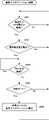
この自動キャリブレーション処理について、図2を参照して説明する。自動キャリブレーション処理は、電子時計100が、磁気センサ131のキャリブレーションを自動的に行うための処理であり、電子時計100が起動すると、他の処理(例えば日時を計時する計時処理)と並行に実行が開始される。 This automatic calibration process will be described with reference to FIG. The automatic calibration process is a process for the electronic clock 100 to automatically calibrate the
まず、電子時計100の制御部120は、磁気センサ131の前回のキャリブレーション(手動キャリブレーションの場合も自動キャリブレーションの場合も含む)から24時間以上経過しているかを判定する(ステップS101)。ここで経過時間を24時間としているのは一例であり、磁気センサ131の正確さをできるだけ保ちたければもっと短い時間(例えば3時間)にしてもよいし、電子時計100の消費電力を抑えたければもっと長い時間(例えば72時間)にしてもよい。 First, the
24時間経過していないなら(ステップS101;No)、ステップS101に戻る。24時間経過していないなら、まだキャリブレーションは行わなくてよいと考えられるからである。24時間以上経過しているなら(ステップS101;Yes)、制御部120は、加速度センサ135で加速度を計測することにより、電子時計100を腕に装着しているユーザの歩行が検知されたか否かを判定する(ステップS102)。なお、加速度センサ135により歩行を検知するアルゴリズムは公知技術である。例えば加速度センサ135が計測した値から、周期的なピークの有無を検知し、歩行を検知することができる。ステップS102は、感知ステップとも呼ばれる。歩行が検知されないなら(ステップS102;No)、ステップS101に戻る。本実施形態では、歩行中の腕の振りに基づいてキャリブレーションを行うため、歩行中でなければ、自動キャリブレーションを行わないからである。 If 24 hours have not passed (step S101; No), the process returns to step S101. This is because if 24 hours have not passed, it is considered that the calibration does not have to be performed yet. If 24 hours or more have passed (step S101; Yes), the
歩行が検知されたら(ステップS102;Yes)、制御部120は、検知した歩行の継続時間が歩行基準時間(例えば60秒)以上であるか否かを判定する(ステップS103)。歩行の継続時間が歩行基準時間未満なら(ステップS103;No)、ステップS101に戻る。継続時間が歩行基準時間未満の場合、今後も歩行が継続するかどうか不明であり、歩行が継続しなかった場合、自動キャリブレーションが途中で失敗するおそれがあるからである。ステップS103では、ステップS102で感知された運動(歩行)の状態が、磁気センサ131のキャリブレーションを行うことが可能なキャリブレーション可能状態であるか否かを判定しているので、ステップS103は判定ステップとも呼ばれる。 When walking is detected (step S102; Yes), the
歩行の継続時間が歩行基準時間以上なら(ステップS103;Yes)、制御部120は、電子時計100の現在の機能モードが時刻モードであるか否かを判定する(ステップS104)。ステップS104は、判別ステップとも呼ばれる。時刻モードでないなら(ステップS104;No)、ステップS101に戻る。機能モードが時刻モードでないなら、ユーザが意図的に現在の機能モードにしていると考えられ、その場合に勝手に磁気センサ131のキャリブレーションが行われてしまうと、ユーザの利便性を損ねるおそれがあるからである。 If the walking duration is equal to or longer than the walking reference time (step S103; Yes), the
電子時計100の現在の機能モードが時刻モードなら(ステップS104;Yes)、制御部120は、磁気センサ131をONにして、自動キャリブレーションを実行し(ステップS105)、ステップS101に戻る。ステップS105では、歩行している時のユーザの腕の振りによって、磁気センサ131の向きが様々な方向に変化することを利用してキャリブレーションを行う。ステップS105は、キャリブレーションステップとも呼ばれる。 If the current functional mode of the electronic clock 100 is the time mode (step S104; Yes), the
以上、自動キャリブレーション処理について説明した。以上説明した自動キャリブレーション処理により、ユーザが手動でキャリブレーションを行わなくても、電子時計100はユーザの運動を感知し、該運動の状態が歩行状態であるなら、自動的にキャリブレーションを行う。したがって、電子時計100は、ユーザに負担をかけずに磁気センサ131のキャリブレーションを行うことができる。なお、歩行状態は、磁気センサ131のキャリブレーションが可能な状態であると言えるので、キャリブレーション可能状態とも呼ぶ。 The automatic calibration process has been described above. By the automatic calibration process described above, the electronic clock 100 senses the user's movement even if the user does not manually calibrate, and if the movement state is the walking state, the electronic clock 100 automatically calibrates. .. Therefore, the electronic clock 100 can calibrate the
また、この自動キャリブレーション処理によるキャリブレーションは電子時計100の現在の機能モードが時刻モード(デフォルトモード)の時しか行われないので、ユーザが他の機能(例えば機能A)を使用している時に自動的にキャリブレーションが行われることによって、機能Aが勝手に終了してしまうようなことを避けることができる。 Further, since the calibration by this automatic calibration process is performed only when the current function mode of the electronic timepiece 100 is the time mode (default mode), when the user is using another function (for example, function A). By automatically performing the calibration, it is possible to prevent the function A from ending without permission.
また、電子時計100は、単に歩行を感知しただけでキャリブレーションを行うのではなく、ある程度の時間(歩行基準時間)歩行が継続していることを確認してからキャリブレーションを行うので、例えば家の中を少し歩いただけのような場合(すぐに歩行が終了してしまう場合)にキャリブレーションが行われるのを防ぐことができる。すぐに歩行が終了してしまうと、キャリブレーションが終了する前に腕の振りの動きがなくなり、キャリブレーションを完了させることができなかったり、キャリブレーションの精度が低くなってしまったりするが、電子時計100では、歩行継続時間が歩行基準時間以上であることを判定してからキャリブレーションを行うことにより、キャリブレーションが失敗したり精度が低くなったりする可能性を低くすることができる。これにより、キャリブレーションが失敗に終わることが少なくなり、消費電力を抑えることができる。 Further, the electronic clock 100 does not calibrate only by detecting walking, but calibrates after confirming that walking has continued for a certain period of time (walking reference time). Therefore, for example, at home. It is possible to prevent calibration from being performed when walking in the inside for a short time (when walking ends immediately). If walking is completed immediately, the movement of the arm swing will be lost before the calibration is completed, and the calibration may not be completed or the calibration accuracy may be low, but electronic. In the clock 100, by performing calibration after determining that the walking continuation time is equal to or longer than the walking reference time, it is possible to reduce the possibility that the calibration fails or the accuracy is lowered. As a result, calibration is less likely to fail, and power consumption can be reduced.
(変形例1)
実施形態1では、電子時計100の機能モードが時刻モード(デフォルトモード)の時にのみ自動キャリブレーション処理を実行する。これは、機能モードが非デフォルトモード(時刻モード以外の機能モード:例えば機能Aモード)であった場合は、ユーザは意図的に(機能Aモードを使いたいから)機能Aモードを実行していると考えられ、そのような場合にキャリブレーションを実行してしまうと、機能Aモードがユーザの意図に反して終了してしまうことになるからである。(Modification 1)
In the first embodiment, the automatic calibration process is executed only when the functional mode of the electronic clock 100 is the time mode (default mode). This is because when the function mode is a non-default mode (function mode other than time mode: for example, function A mode), the user intentionally executes the function A mode (because he / she wants to use the function A mode). This is because if the calibration is executed in such a case, the function A mode will be terminated against the intention of the user.
一方、キャリブレーション中にユーザが非デフォルトモード(時刻モード以外の機能モード:例えば機能Aモード)を実行した場合、ユーザは機能Aモードで行われる表示を確認するために立ち止まって(歩行を中止して)表示部132を見ることが多いと考えられる。すると、腕の振りが止まってしまうので、この時行われているキャリブレーションは失敗してしまうことが予想される。失敗が予想されるキャリブレーションを続行するのは、消費電力の面でも望ましくない。そこで、キャリブレーション中にユーザが非デフォルトモード(時刻モード以外の機能モード)を実行した場合にキャリブレーションを中止する変形例1について説明する。 On the other hand, if the user executes a non-default mode (function mode other than time mode: for example, function A mode) during calibration, the user stops (stops walking) to check the display performed in function A mode. It is considered that the
変形例1に係る電子時計100の機能構成は、実施形態1に係る電子時計100と同じであり、図1に示される。変形例1に係る電子時計100が実施形態1に係る電子時計100と異なる点は、変形例1では、自動キャリブレーション処理(図2)に加えて、キャリブレーション実行中に機能モードの変化を監視して、ユーザが非デフォルトモード(時刻モード以外の機能モード)を実行した場合にキャリブレーションを中止するための処理(キャリブレーション中止処理)を実行する点である。このキャリブレーション中止処理について、図3を参照して説明する。この処理は、変形例1に係る電子時計100が起動すると、他の処理(例えば計時処理)と並行に実行が開始される。 The functional configuration of the electronic clock 100 according to the first modification is the same as that of the electronic clock 100 according to the first embodiment, and is shown in FIG. The difference between the electronic clock 100 according to the first modification and the electronic clock 100 according to the first embodiment is that in the first modification, in addition to the automatic calibration process (FIG. 2), the change in the functional mode is monitored during the execution of the calibration. Then, when the user executes the non-default mode (functional mode other than the time mode), the process for canceling the calibration (calibration cancel process) is executed. This calibration cancellation process will be described with reference to FIG. When the electronic clock 100 according to the first modification is activated, this process is started to be executed in parallel with other processes (for example, timekeeping process).
まず、電子時計101の制御部120は、磁気センサ131のキャリブレーションが開始されているか否かを判定する(ステップS151)。例えば、手動キャリブレーション時も自動キャリブレーション時も、キャリブレーションが開始されたら、キャリブレーション中であることを示すフラグ変数に1をセットし、キャリブレーションが終了したら、そのフラグ変数を0にするようにしておくことにより、制御部120は、そのフラグ変数を確認することによってキャリブレーションが開始されているか否かを判定できる。キャリブレーションが開始されていなければ(ステップS151;No)、ステップS151に戻る。 First, the
キャリブレーションが開始されていれば(ステップS151;Yes)、制御部120は、磁気センサ131のキャリブレーションが終了しているか否かを判定する(ステップS152)。この判定もステップS151と同様の処理で行うことができる。キャリブレーションが終了しているなら(ステップS152;Yes)、ステップS151に戻る。 If the calibration has been started (step S151; Yes), the
キャリブレーションが終了していないなら(ステップS152;No)、制御部120は、非デフォルトモード(時刻モード以外の機能モード)が実行されたか否かを判定する(ステップS153)。この判定は、ユーザが操作部133を操作して、非デフォルトモード(時刻モード以外の機能モード)を実行したか否かを検知することにより行うことができる。非デフォルトモード(時刻モード以外の機能モード)が実行されていなければ(ステップS153;No)、ステップS152に戻る。 If the calibration is not completed (step S152; No), the
非デフォルトモード(時刻モード以外の機能モード)が実行されたら(ステップS153;Yes)、制御部120は、磁気センサ131をOFFにして、キャリブレーションを中止する(ステップS154)。そして、ステップS151に戻る。 When the non-default mode (functional mode other than the time mode) is executed (step S153; Yes), the
上述のキャリブレーション中止処理(図3)により、ユーザが非デフォルトモード(時刻モード以外の機能モード)を実行した場合には、電子時計100は、磁気センサ131のキャリブレーションを中止するので、失敗する可能性が高いキャリブレーションを実行し続けるのを防ぎ、消費電力を低減することができる。 When the user executes the non-default mode (function mode other than the time mode) by the calibration cancellation process (FIG. 3) described above, the electronic clock 100 cancels the calibration of the
なお、上述のキャリブレーション中止処理(図3)は、変形例1に係る電子時計100が起動すると、他の処理(例えば計時処理)と並行に実行が開始されるとして説明したが、実行開始タイミングはこれに限られない。キャリブレーション(手動も自動も含む)を実行する時にキャリブレーション中止処理が実行されるようにしてもよい。その場合は、ステップS151の処理は省略でき、また、上述の図3の説明で「ステップS151に戻る。」としていた部分は「キャリブレーション中止処理を終了する。」に置き換えればよい。 Although the above-mentioned calibration cancellation process (FIG. 3) has been described as being started in parallel with other processes (for example, timekeeping process) when the electronic clock 100 according to the first modification is activated, the execution start timing has been described. Is not limited to this. The calibration cancellation process may be executed when the calibration (both manual and automatic) is executed. In that case, the process of step S151 can be omitted, and the portion of "returning to step S151" in the above description of FIG. 3 may be replaced with "terminate the calibration stop process."
(変形例2)
実施形態1では、前回のキャリブレーションから24時間経過後は、電子時計100はユーザが歩行しているか否かの判定をし続けるが、この判定には加速度センサ135を用いるので、加速度センサ135の動作に必要な電力を消費し続けてしまうという問題があった。ユーザが歩行等、何らかの運動をしていることは、加速度センサ135だけでなく、傾斜センサ136によっても感知可能である。そして、一般に傾斜センサ136は加速度センサ135よりも消費電力が小さい。そこで、傾斜センサ136が所定の傾斜を検知した後に加速度センサ135を用いる変形例2について説明する。(Modification 2)
In the first embodiment, after 24 hours have passed from the previous calibration, the electronic clock 100 continues to determine whether or not the user is walking, but since the
変形例2に係る電子時計100の機能構成は、実施形態1に係る電子時計100と同じであり、図1に示される。変形例2に係る電子時計100が実施形態1に係る電子時計100と異なる点は、変形例2では、自動キャリブレーション処理において、加速度センサ135で歩行を検知する前に、まず、傾斜センサでユーザが動いていることを検知する点である。この変形例2に係る自動キャリブレーション処理について、図4を参照して説明する。この処理は、変形例2に係る電子時計100が起動すると、他の処理(例えば計時処理)と並行に実行が開始される。 The functional configuration of the electronic clock 100 according to the second modification is the same as that of the electronic clock 100 according to the first embodiment, and is shown in FIG. The difference between the electronic clock 100 according to the second modification and the electronic clock 100 according to the first embodiment is that in the second modification, before the
変形例2に係る自動キャリブレーション処理(図4)は、実施形態1に係る自動キャリブレーション処理(図2)のステップS101とステップS102の間にステップS111を追加した処理になっている。そこで、ステップS111について説明する。ステップS111では、制御部120は、傾斜センサ136で測定した傾きが前回測定した傾きから変化したか否かを判定する。変化していなければ(ステップS111;No)、ステップS101に戻る。変化していたら(ステップS111;Yes)、制御部120は、加速度センサ135により、電子時計100を腕に装着しているユーザの歩行が検知されたか否かを判定する(ステップS102)。 The automatic calibration process (FIG. 4) according to the second modification is a process in which step S111 is added between steps S101 and S102 of the automatic calibration process (FIG. 2) according to the first embodiment. Therefore, step S111 will be described. In step S111, the
上述の処理以外は、実施形態1に係る自動キャリブレーション処理(図2)と同じであるので、説明を省略する。変形例2に係る電子時計100では、加速度センサ135で歩行を検知する前に、傾斜センサ136でユーザが動いているか否かを確認するので、消費電力を軽減することができる。 Other than the above-mentioned processing, it is the same as the automatic calibration processing (FIG. 2) according to the first embodiment, and thus the description thereof will be omitted. In the electronic clock 100 according to the second modification, before the
(実施形態2)
実施形態1では、電子時計100は、ユーザの歩行を検知してキャリブレーションを行ったが、キャリブレーションを行うタイミングは、ユーザの歩行に限られない。電子時計を腕に装着しているユーザが腕にある電子時計を見る動作は、比較的頻繁に行われると考えられるが、この動作の後にユーザは通常、腕を振り下ろす動作をする。この、腕を振り下ろす動作は、歩行中の腕の振りと同様に、腕に装着された電子時計を、向きを変えながら移動させる動作になるので、この動作においてもキャリブレーションを行うことが可能である。そこで、電子時計の表示を見る動作をきっかけに自動的にキャリブレーションを行う実施形態2について説明する。(Embodiment 2)
In the first embodiment, the electronic clock 100 detects the walking of the user and performs calibration, but the timing of performing the calibration is not limited to the walking of the user. The movement of a user wearing an electronic watch on his arm to look at the electronic watch on his arm is considered to be relatively frequent, but after this movement, the user usually swings his arm down. This movement of swinging the arm down is a movement of moving the electronic clock attached to the arm while changing the direction, similar to the movement of the arm while walking, so it is possible to perform calibration in this movement as well. Is. Therefore, the second embodiment in which the calibration is automatically performed triggered by the operation of viewing the display of the electronic clock will be described.
実施形態2に係る電子時計101の機能構成は、実施形態1に係る電子時計100と同じであり、図1に示される。また、実施形態2に係る電子時計101の持つ機能モードも実施形態1に係る電子時計100の持つ機能モードと同じであり、手動キャリブレーション機能も実施形態2に係る電子時計101と実施形態1に係る電子時計100とで特段異なる点はない。一方、実施形態2に係る電子時計101の自動キャリブレーション処理は、実施形態1に係る電子時計100の自動キャリブレーション処理(図2)と異なるので、電子時計101の自動キャリブレーション処理について、図5を参照して説明する。この自動キャリブレーション処理は、電子時計101が起動すると、他の処理(例えば計時処理)と並行に実行が開始される。 The functional configuration of the electronic clock 101 according to the second embodiment is the same as that of the electronic clock 100 according to the first embodiment, and is shown in FIG. Further, the functional mode of the electronic clock 101 according to the second embodiment is the same as the functional mode of the electronic clock 100 according to the first embodiment, and the manual calibration function is also included in the electronic clock 101 and the first embodiment according to the second embodiment. There is no particular difference from the electronic clock 100. On the other hand, the automatic calibration process of the electronic clock 101 according to the second embodiment is different from the automatic calibration process of the electronic clock 100 according to the first embodiment (FIG. 2). Will be described with reference to. When the electronic clock 101 is activated, this automatic calibration process is started to be executed in parallel with other processes (for example, timekeeping process).
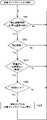
まず、電子時計101の制御部120は、磁気センサ131の前回のキャリブレーション(手動キャリブレーションの場合も自動キャリブレーションの場合も含む)から24時間以上経過しているかを判定する(ステップS201)。実施形態1と同様、ここで経過時間を24時間としているのは一例であり、磁気センサ131の正確さをできるだけ保ちたければもっと短い時間(例えば3時間)にしてもよいし、電子時計101の消費電力を抑えたければもっと長い時間(例えば72時間)にしてもよい。 First, the
24時間経過していないなら(ステップS201;No)、ステップS201に戻る。24時間経過していないなら、まだキャリブレーションは行わなくてよいと考えられるからである。24時間以上経過しているなら(ステップS201;Yes)、制御部120は、加速度センサ135による加速度の変化、又は、傾斜センサ136による電子時計101の傾き、又は、加速度センサ135による加速度の変化と傾斜センサ136による電子時計101の傾きの両方を用いて、電子時計101を腕に装着しているユーザが、電子時計101(表示部132)を見る動作を行ったか否かを判定する(ステップS202)。腕が自然に下に下がっている状態から、ユーザが電子時計101の表示部132を見る時の動作が行われる時の電子時計101装着部分の加速度変化や、ユーザが表示部132を見る時の電子時計101の傾き等から、ユーザが電子時計101(表示部132)を見る動作を行ったか否かを判定することが可能である。電子時計101(表示部132)を見る動作が行われていないなら(ステップS202;No)、ステップS201に戻る。本実施形態では、電子時計101(表示部132)を見る動作の後の腕の振りに基づいてキャリブレーションを行うため、電子時計101(表示部132)を見る動作が行われなければ、自動キャリブレーションを行わないからである。 If 24 hours have not passed (step S201; No), the process returns to step S201. This is because if 24 hours have not passed, it is considered that the calibration does not have to be performed yet. If 24 hours or more have passed (step S201; Yes), the
電子時計101(表示部132)を見る動作が行われたら(ステップS202;Yes)、制御部120は、加速度センサ135により、電子時計101が静止している状態が継続しているか否かを判定する(ステップS203)。電子時計101が静止している状態が継続しているなら(ステップS203;Yes)、ステップS203に戻る。静止状態が継続している間はユーザが電子時計101(表示部132)を見続けていると考えられ、腕の振りの動きが始まっていないからである。 When the operation of viewing the electronic clock 101 (display unit 132) is performed (step S202; Yes), the
電子時計101が静止している状態が継続していないなら(ステップS203;No)、制御部120は、電子時計101の現在の機能モードが時刻モードであるか否かを判定する(ステップS204)。時刻モードでないなら(ステップS204;No)、ステップS201に戻る。機能モードが時刻モードでないなら、ユーザが意図的に現在の機能モードにしていると考えられ、その場合に勝手に磁気センサ131のキャリブレーションが行われてしまうと、ユーザの利便性を損ねるおそれがあるからである。 If the state in which the electronic clock 101 is stationary is not continued (step S203; No), the
電子時計101の現在の機能モードが時刻モードなら(ステップS204;Yes)、制御部120は、磁気センサ131をONにして、自動キャリブレーションを実行し(ステップS205)、ステップS201に戻る。ステップS205では、ユーザが電子時計101(表示部132)を見るために上げていた腕を振り下ろす動作によって、磁気センサ131の向きが様々な方向に変化することを利用してキャリブレーションを行う。すなわち、電子時計101では、ユーザが電子時計101を見る動作を判定してからキャリブレーションを行う。これにより、その後ユーザが電子時計101を見るために上げていた腕を振り下ろして、磁気センサ131の向きが様々な方向に変化するタイミングを確実に利用できるため、キャリブレーションが失敗したり精度が低くなったりする可能性を低くすることができる。これにより、キャリブレーションが失敗に終わることが少なくなり、消費電力を抑えることができる。 If the current functional mode of the electronic clock 101 is the time mode (step S204; Yes), the
以上、実施形態2に係る自動キャリブレーション処理について説明した。以上説明した自動キャリブレーション処理により、ユーザが手動でキャリブレーションを行わなくても、電子時計101はユーザの運動を感知し、該運動の状態が電子時計101を見る動作状態であるなら、自動的にキャリブレーションを行う。したがって、電子時計101は、ユーザに負担をかけずに磁気センサ131のキャリブレーションを行うことができる。なお、電子時計101を見る動作状態も、磁気センサ131のキャリブレーションが可能な状態であると言えるので、キャリブレーション可能状態とも呼ぶ。 The automatic calibration process according to the second embodiment has been described above. By the automatic calibration process described above, the electronic clock 101 senses the user's movement without manually performing calibration, and if the state of the movement is the operating state of viewing the electronic clock 101, it is automatically performed. Calibrate to. Therefore, the electronic clock 101 can calibrate the
また、このキャリブレーションは電子時計101の現在の機能モードが時刻モードの時しか行われないので、ユーザが他の機能(例えば機能A)を使用している時に自動的にキャリブレーションが行われることによって、機能Aが勝手に終了してしまうようなことを避けることができる。 Further, since this calibration is performed only when the current function mode of the electronic clock 101 is the time mode, the calibration is automatically performed when the user is using another function (for example, function A). Therefore, it is possible to prevent the function A from ending without permission.
(実施形態3)
キャリブレーションを行うタイミングとしては、他にも考えられる。例えば、電子時計が机の上などに置かれて静止している状態から、ユーザがその電子時計を取って、腕に装着する動作をするタイミングである。このタイミングでは、ユーザが電子時計を取って腕に装着するまでに電子時計は向きを変えながら移動することになるので、キャリブレーションを行うことが可能である。そこで、腕に装着するタイミングで自動的にキャリブレーションを行う実施形態3について説明する。(Embodiment 3)
There are other possible timings for calibration. For example, it is the timing when the user picks up the electronic watch and puts it on his / her arm from a state where the electronic watch is placed on a desk or the like and is stationary. At this timing, the electronic clock moves while changing its direction by the time the user picks up the electronic clock and wears it on the wrist, so that calibration can be performed. Therefore, the third embodiment in which calibration is automatically performed at the timing of wearing the wrist will be described.
実施形態3に係る電子時計102の機能構成は、実施形態1に係る電子時計100と同じであり、図1に示される。また、実施形態3に係る電子時計102の持つ機能モードも実施形態1に係る電子時計100の持つ機能モードと同じであり、手動キャリブレーション機能も実施形態3に係る電子時計102と実施形態1に係る電子時計100とで特段異なる点はない。一方、実施形態3に係る電子時計102の自動キャリブレーション処理は、実施形態1に係る電子時計100の自動キャリブレーション処理(図2)と異なるので、電子時計102の自動キャリブレーション処理について、図6を参照して説明する。この自動キャリブレーション処理は、電子時計102が起動すると、他の処理(例えば計時処理)と並行に実行が開始される。 The functional configuration of the electronic clock 102 according to the third embodiment is the same as that of the electronic clock 100 according to the first embodiment, and is shown in FIG. Further, the functional mode of the electronic clock 102 according to the third embodiment is the same as the functional mode of the electronic clock 100 according to the first embodiment, and the manual calibration function is also included in the electronic clock 102 and the first embodiment according to the third embodiment. There is no particular difference from the electronic clock 100. On the other hand, the automatic calibration process of the electronic clock 102 according to the third embodiment is different from the automatic calibration process of the electronic clock 100 according to the first embodiment (FIG. 2). Will be described with reference to. When the electronic clock 102 is activated, this automatic calibration process is started to be executed in parallel with other processes (for example, timekeeping process).
まず、電子時計102の制御部120は、加速度センサ135による加速度の変化、若しくは、傾斜センサ136による傾きの変化、又は、加速度センサ135による加速度の変化と傾斜センサ136による傾きの変化の両方を用いて、電子時計102が静止し続けている時間(静止継続時間)が静止基準時間(例えば3時間)以上であるか否かを判定する(S301)。静止継続時間が静止基準時間未満なら(ステップS301;No)、ステップS301に戻る。 First, the
静止継続時間が静止基準時間以上なら(ステップS301;Yes)、制御部120は、加速度センサ135による加速度の変化、若しくは、傾斜センサ136による傾きの変化、又は、加速度センサ135による加速度の変化と傾斜センサ136による傾きの変化の両方を用いて、電子時計102が動いた(位置や向きが変化した)か否かを判定する(ステップS302)。電子時計102が動いて(位置や向きが変化して)いなければ(ステップS302;No)、ステップS301に戻る。 If the rest duration is equal to or longer than the rest reference time (step S301; Yes), the
電子時計102が動いた(位置や向きが変化した)なら(ステップS302;Yes)、制御部120は、磁気センサ131の前回のキャリブレーション(手動キャリブレーションの場合も自動キャリブレーションの場合も含む)から24時間以上経過しているかを判定する(ステップS303)。実施形態1と同様、ここで経過時間を24時間としているのは一例であり、磁気センサ131の正確さをできるだけ保ちたければもっと短い時間(例えば3時間)にしてもよいし、電子時計102の消費電力を抑えたければもっと長い時間(例えば72時間)にしてもよい。 If the electronic clock 102 has moved (position or orientation has changed) (step S302; Yes), the
24時間経過していないなら(ステップS303;No)、ステップS301に戻る。24時間経過していないなら、まだキャリブレーションは行わなくてよいと考えられるからである。24時間以上経過しているなら(ステップS303;Yes)、制御部120は、電子時計102の現在の機能モードが時刻モードであるか否かを判定する(ステップS304)。時刻モードでないなら(ステップS304;No)、ステップS301に戻る。機能モードが時刻モードでないなら、ユーザが意図的に現在の機能モードにしていると考えられ、その場合に勝手に磁気センサ131のキャリブレーションが行われてしまうと、ユーザの利便性を損ねるおそれがあるからである。 If 24 hours have not passed (step S303; No), the process returns to step S301. This is because if 24 hours have not passed, it is considered that the calibration does not have to be performed yet. If 24 hours or more have passed (step S303; Yes), the
電子時計102の現在の機能モードが時刻モードなら(ステップS304;Yes)、制御部120は、磁気センサ131をONにして、自動キャリブレーションを実行し(ステップS305)、ステップS301に戻る。ステップS305では、ユーザにより電子時計102が腕に装着される時の動きによって、磁気センサ131の向きが様々な方向に変化することを利用してキャリブレーションを行う。すなわち、電子時計102では、ユーザが電子時計102を腕に装着するために電子時計102を動かしたことを判定してからキャリブレーションを行う。これにより、その後ユーザが電子時計102を腕に装着するなどして、磁気センサ131の向きが様々な方向に変化するタイミングを確実に利用できるため、キャリブレーションが失敗したり精度が低くなったりする可能性を低くすることができる。これにより、キャリブレーションが失敗に終わることが少なくなり、消費電力を抑えることができる。 If the current functional mode of the electronic clock 102 is the time mode (step S304; Yes), the
以上、実施形態3に係る自動キャリブレーション処理について説明した。以上説明した自動キャリブレーション処理により、ユーザが手動でキャリブレーションを行わなくても、電子時計102はユーザの運動を感知し、該運動の状態が電子時計102を腕に装着する動作状態であるなら、自動的にキャリブレーションを行う。したがって、電子時計102は、ユーザに負担をかけずに磁気センサ131のキャリブレーションを行うことができる。なお、電子時計102を腕に装着する動作状態も、磁気センサ131のキャリブレーションが可能な状態であると言えるので、キャリブレーション可能状態とも呼ぶ。 The automatic calibration process according to the third embodiment has been described above. If the electronic watch 102 senses the user's movement by the automatic calibration process described above and the user does not manually calibrate, and the state of the movement is the operation state in which the electronic watch 102 is attached to the arm. , Automatically calibrate. Therefore, the electronic clock 102 can calibrate the
また、このキャリブレーションは電子時計102の現在の機能モードが時刻モードの時しか行われないので、ユーザが他の機能(例えば機能A)を使用している時に自動的にキャリブレーションが行われることによって、機能Aが勝手に終了してしまうようなことを避けることができる。 Further, since this calibration is performed only when the current function mode of the electronic clock 102 is the time mode, the calibration is automatically performed when the user is using another function (for example, function A). Therefore, it is possible to prevent the function A from ending without permission.
(実施形態4)
キャリブレーションを行うタイミングとしては、他にも考えられる。例えば、ユーザが電子時計のバンドを外すタイミングである。このタイミングでは、ユーザが電子時計のバンドを外し、電子時計を腕から外して机の上等に置くまでに電子時計は向きを変えながら移動することになるので、キャリブレーションを行うことが可能である。そこで、ユーザが電子時計のバンドを外す動作をきっかけに自動的にキャリブレーションを行う実施形態4について説明する。(Embodiment 4)
There are other possible timings for calibration. For example, it is the timing when the user removes the band of the electronic watch. At this timing, the user can remove the band of the electronic watch, remove the electronic watch from his arm and place it on a desk, etc., and the electronic watch will move while changing its direction, so calibration can be performed. be. Therefore, a fourth embodiment will be described in which calibration is automatically performed when the user removes the band of the electronic timepiece.
実施形態4に係る電子時計103の機能構成は、実施形態1に係る電子時計100と同じであり、図1に示される。また、実施形態4に係る電子時計103の持つ機能モードも実施形態1に係る電子時計100の持つ機能モードと同じであり、手動キャリブレーション機能も実施形態4に係る電子時計103と実施形態1に係る電子時計100とで特段異なる点はない。一方、実施形態4に係る電子時計103の自動キャリブレーション処理は、実施形態1に係る電子時計100の自動キャリブレーション処理(図2)と異なるので、電子時計103の自動キャリブレーション処理について、図7を参照して説明する。この自動キャリブレーション処理は、電子時計103が起動すると、他の処理(例えば計時処理)と並行に実行が開始される。 The functional configuration of the electronic clock 103 according to the fourth embodiment is the same as that of the electronic clock 100 according to the first embodiment, and is shown in FIG. Further, the functional mode of the electronic clock 103 according to the fourth embodiment is the same as the functional mode of the electronic clock 100 according to the first embodiment, and the manual calibration function is also included in the electronic clock 103 and the first embodiment according to the fourth embodiment. There is no particular difference from the electronic clock 100. On the other hand, the automatic calibration process of the electronic clock 103 according to the fourth embodiment is different from the automatic calibration process of the electronic clock 100 according to the first embodiment (FIG. 2). Will be described with reference to. When the electronic clock 103 is activated, this automatic calibration process is started to be executed in parallel with other processes (for example, timekeeping process).
まず、電子時計103の制御部120は、磁気センサ131の前回のキャリブレーション(手動キャリブレーションの場合も自動キャリブレーションの場合も含む)から24時間以上経過しているかを判定する(ステップS401)。実施形態1と同様、ここで経過時間を24時間としているのは一例であり、磁気センサ131の正確さをできるだけ保ちたければもっと短い時間(例えば3時間)にしてもよいし、電子時計103の消費電力を抑えたければもっと長い時間(例えば72時間)にしてもよい。 First, the
24時間経過していないなら(ステップS401;No)、ステップS401に戻る。24時間経過していないなら、まだキャリブレーションは行わなくてよいと考えられるからである。24時間以上経過しているなら(ステップS401;Yes)、制御部120は、加速度センサ135による加速度の変化、又は、傾斜センサ136による電子時計103の傾き、又は、加速度センサ135による加速度の変化と傾斜センサ136による電子時計103の傾きの両方を用いて、電子時計103を腕に装着しているユーザが、電子時計103のバンドを外す動作を行ったか否かを判定する(ステップS402)。 If 24 hours have not passed (step S401; No), the process returns to step S401. This is because if 24 hours have not passed, it is considered that the calibration does not have to be performed yet. If 24 hours or more have passed (step S401; Yes), the
ユーザが電子時計103のバンドを外す際には、バンドを外す際に特有の、手首を回転させる動作を行うので、ステップS402では、制御部120は、この手首の動き等から、ユーザがバンドを外す動作を行ったか否かを判定することが可能である。また、電子時計103は、バンド部分にバンドの装着及び取り外しを感知できるバンド装着センサを備えてもよい。バンド装着センサを備えている電子時計103であれば、制御部120は、バンド装着センサによる感知結果によって、バンドが外されたか否かを判定することができる。 When the user removes the band of the electronic watch 103, the operation of rotating the wrist, which is peculiar to the removal of the band, is performed. Therefore, in step S402, the
バンドが外されていないなら(ステップS402;No)、ステップS401に戻る。本実施形態では、電子時計103を取り外してからの電子時計103の動きに基づいてキャリブレーションを行うため、電子時計103を取り外す動作が行われなければ、自動キャリブレーションを行わないからである。 If the band has not been removed (step S402; No), the process returns to step S401. This is because in the present embodiment, the calibration is performed based on the movement of the electronic clock 103 after the electronic clock 103 is removed, so that the automatic calibration is not performed unless the operation of removing the electronic clock 103 is performed.
バンドが外されたら(ステップS402;Yes)、制御部120は、電子時計103の現在の機能モードが時刻モードであるか否かを判定する(ステップS403)。時刻モードでないなら(ステップS403;No)、ステップS401に戻る。機能モードが時刻モードでないなら、ユーザが意図的に現在の機能モードにしていると考えられ、その場合に勝手に磁気センサ131のキャリブレーションが行われてしまうと、ユーザの利便性を損ねるおそれがあるからである。もっとも、バンドを外した後は、再度装着するまでの間、ユーザは電子時計103を使わないとも考えられるので、ステップS403の処理は省略されてもよい。 When the band is removed (step S402; Yes), the
ステップS403の処理が省略されない場合には、ステップS403で電子時計103の現在の機能モードが時刻モードなら(ステップS403;Yes)、制御部120は、磁気センサ131をONにして、自動キャリブレーションを実行し(ステップS404)、ステップS401に戻る。ステップS404では、ユーザが電子時計103を腕から取り外して机の上等に置く動作によって、磁気センサ131の向きが様々な方向に変化することを利用してキャリブレーションを行う。すなわち、電子時計103では、電子時計103を腕から外したことを判定してからキャリブレーションを行う。これにより、ユーザが電子時計103を机の上等に置くなどして、磁気センサ131の向きが様々な方向に変化するタイミングを確実に利用できるため、キャリブレーションが失敗したり精度が低くなったりする可能性を低くすることができる。これにより、キャリブレーションが失敗に終わることが少なくなり、消費電力を抑えることができる。 If the process of step S403 is not omitted and the current functional mode of the electronic clock 103 is the time mode in step S403 (step S403; Yes), the
以上、実施形態4に係る自動キャリブレーション処理について説明した。以上説明した自動キャリブレーション処理により、ユーザが手動でキャリブレーションを行わなくても、電子時計103はユーザの運動を感知し、該運動の状態が電子時計103を腕から外す動作状態であるなら、自動的にキャリブレーションを行う。したがって、電子時計103は、ユーザに負担をかけずに磁気センサ131のキャリブレーションを行うことができる。なお、電子時計103を腕から外す動作状態も、磁気センサ131のキャリブレーションが可能な状態であると言えるので、キャリブレーション可能状態とも呼ぶ。 The automatic calibration process according to the fourth embodiment has been described above. By the automatic calibration process described above, if the electronic clock 103 senses the user's movement without manually performing calibration, and the state of the movement is the operation state of removing the electronic clock 103 from the arm. Calibrate automatically. Therefore, the electronic clock 103 can calibrate the
なお、本発明は、上述の実施形態に限られるものではなく、様々に組み合わせたり変更したりすることができる。例えば、上述の実施形態では、磁気センサを備えるウェアラブル機器の一例として電子時計を挙げて説明しているが、本発明は、電子時計に限られず、スマートウォッチ、活動量計等の、磁気センサを備える任意のウェアラブル機器に適用することができる。電子時計は日時を計時する計時部を備える必要があるが、本発明を、日時を計時しなくてもよいウェアラブル機器に適用する場合、該ウェアラブル機器は計時部を備えなくてもよい。 The present invention is not limited to the above-described embodiment, and can be combined or modified in various ways. For example, in the above-described embodiment, an electronic watch is described as an example of a wearable device including a magnetic sensor, but the present invention is not limited to the electronic watch, but a magnetic sensor such as a smart watch or an activity meter is used. It can be applied to any wearable device provided. The electronic clock needs to be provided with a timekeeping unit, but when the present invention is applied to a wearable device that does not require timekeeping, the wearable device may not be provided with a timekeeping unit.
また、上述の各実施形態における自動キャリブレーション処理を組み合わせることにより、自動的に磁気センサのキャリブレーションを行うタイミングを増やすことができる。例えば、実施形態1と実施形態2とを組み合わせれば、ユーザが歩行している時だけでなく、表示部132を見る動作を行った時にも自動キャリブレーションが行われるので、磁気センサ131の精度をより向上させることができる。 Further, by combining the automatic calibration processing in each of the above-described embodiments, the timing for automatically calibrating the magnetic sensor can be increased. For example, if the first embodiment and the second embodiment are combined, the accuracy of the
また、例えば、実施形態2~4と変形例1とを組み合わせることにより、実施形態2~4に係る電子時計101,102,103においても、キャリブレーションの途中でユーザが機能モードを時刻モード以外(非デフォルトモード)に変更した場合にはキャリブレーションを中止することができ、無駄な電力消費を防ぐことができる。 Further, for example, by combining the second to fourth embodiments and the first modification, even in the electronic clocks 101, 102, and 103 according to the second to fourth embodiments, the user sets the function mode to a mode other than the time mode during calibration ( When changing to the non-default mode), calibration can be stopped and wasteful power consumption can be prevented.
なお、上述の各実施形態に係る電子時計100,101,102,103は、圧力センサ137を備えるものとして説明した。しかし、電子時計100,101,102,103が、圧力センサ137を必要する機能モード(気圧計測モード、高度計測モード等)を備える必要がないなら、電子時計100,101,102,103は、圧力センサ137を備えなくてもよい。 The electronic clocks 100, 101, 102, and 103 according to each of the above-described embodiments have been described as including the
また、上述の各実施形態に係る電子時計100,101,102,103は、温度センサ138を備えるものとして説明した。しかし、電子時計100,101,102,103が、温度センサ138を要する機能モード(温度計測モード等)を備える必要がないなら、電子時計100,101,102,103は、温度センサ138を備えなくてもよい。 Further, the electronic clocks 100, 101, 102, and 103 according to each of the above-described embodiments have been described as being provided with the
また、加速度センサ135により歩行を検知すると方法として、例えば加速度センサが計測した値から、周期的なピークの有無を検知し、歩行を検知することができると説明した。しかし、この方法に限らず、加速度センサ135の出力に基づいた歩行検知方法であれば任意の方法で歩行を検知してよい。 Further, it was explained that walking can be detected by detecting the presence or absence of a periodic peak from the value measured by the acceleration sensor, for example, as a method of detecting walking by the
なお、電子時計100,101,102,103の各機能は、携帯可能なPC(Personal Computer)等のコンピュータによっても実施することができる。具体的には、上記実施形態では、電子時計100,101,102,103が行う自動キャリブレーション処理のプログラムが、ROM134に予め記憶されているものとして説明した。しかし、プログラムを、フレキシブルディスク、CD-ROM(Compact Disc Read Only Memory)、DVD(Digital Versatile Disc)、MO(Magneto-Optical Disc)、メモリカード、USB(Universal Serial Bus)メモリ等のコンピュータ読み取り可能な記録媒体に格納して配布し、そのプログラムをコンピュータに読み込んでインストールすることにより、上述の各機能を実現することができるコンピュータを構成してもよい。 The functions of the electronic clocks 100, 101, 102, and 103 can also be performed by a computer such as a portable PC (Personal Computer). Specifically, in the above embodiment, the program of the automatic calibration process performed by the electronic clocks 100, 101, 102, and 103 has been described as being stored in the
以上、本発明の好ましい実施形態について説明したが、本発明は係る特定の実施形態に限定されるものではなく、本発明には、特許請求の範囲に記載された発明とその均等の範囲が含まれる。以下に、本願出願の当初の特許請求の範囲に記載された発明を付記する。 Although the preferred embodiment of the present invention has been described above, the present invention is not limited to the specific embodiment, and the present invention includes the invention described in the claims and the equivalent range thereof. Will be. The inventions described in the original claims of the present application are described below.
(付記1)
磁気センサと、
前記磁気センサのキャリブレーションを行い、2以上の機能モードを制御する制御部と、
ユーザの運動を感知する運動感知部と、
を備え、
前記制御部は、
前記運動感知部で感知された運動の状態が前記磁気センサのキャリブレーションを行うことが可能なキャリブレーション可能状態であるか否かを判定し、前記2以上の機能モードのうち現在実行中の機能モードを判別し、
前記運動感知部で感知された運動の状態が、前記キャリブレーション可能状態であり、かつ、前記機能モードが、ユーザの操作によって実行される機能モードである非デフォルトモードでない場合、前記磁気センサのキャリブレーションを行い、
前記運動感知部で感知された運動の状態が前記キャリブレーション可能状態でない、又は、前記制御部により判別された機能モードが前記非デフォルトモードである場合、前記磁気センサのキャリブレーションを行わない、
ウェアラブル機器。(Appendix 1)
With a magnetic sensor
A control unit that calibrates the magnetic sensor and controls two or more functional modes.
A motion sensing unit that senses the user's motion,
Equipped with
The control unit
It is determined whether or not the state of motion sensed by the motion sensing unit is a calibable state in which the magnetic sensor can be calibrated, and the function currently being executed among the two or more functional modes is determined. Determine the mode and
Calibration of the magnetic sensor when the state of motion sensed by the motion sensing unit is the calibrationable state and the functional mode is not the non-default mode which is the functional mode executed by the user's operation. To perform the motion
If the state of motion sensed by the motion sensing unit is not the calibrationable state, or the functional mode determined by the control unit is the non-default mode, the magnetic sensor is not calibrated.
Wearable device.
(付記2)
前記キャリブレーション可能状態は、歩行状態である、
付記1に記載のウェアラブル機器。(Appendix 2)
The calibable state is a walking state.
The wearable device described in Appendix 1.
(付記3)
前記制御部は、
前記歩行状態の継続時間が所定の歩行基準時間以上の場合、前記磁気センサのキャリブレーションを行い、
前記歩行状態の継続時間が前記歩行基準時間未満の場合、前記磁気センサのキャリブレーションを行わない、
付記2に記載のウェアラブル機器。(Appendix 3)
The control unit
When the duration of the walking state is equal to or longer than the predetermined walking reference time, the magnetic sensor is calibrated.
If the duration of the walking state is less than the walking reference time, the magnetic sensor is not calibrated.
The wearable device described in Appendix 2.
(付記4)
前記キャリブレーション可能状態は、前記ウェアラブル機器を見るために上げていた腕を振り下ろす動作、前記ウェアラブル機器を腕に装着する動作、及び、前記ウェアラブル機器を腕から外して置く動作のうちの少なくとも1つの動作を行う状態を含む、
付記1から3のいずれか1つに記載のウェアラブル機器。(Appendix 4)
The calibrator-enabled state is at least one of an operation of swinging down the arm raised to see the wearable device, an operation of attaching the wearable device to the arm, and an operation of removing the wearable device from the arm. Including the state of performing two actions,
The wearable device according to any one of Supplementary note 1 to 3.
(付記5)
前記制御部は、キャリブレーションを行っている間に、前記制御部により判別された機能モードが前記非デフォルトモードに変化した場合、該キャリブレーションを中止する、
付記1から4のいずれか1つに記載のウェアラブル機器。(Appendix 5)
If the functional mode determined by the control unit changes to the non-default mode while the calibration is being performed, the control unit cancels the calibration.
The wearable device according to any one of Supplementary note 1 to 4.
(付記6)
さらに、前記ウェアラブル機器の傾きを計測する傾斜計測部を備え、
前記運動感知部は、
前記傾斜計測部で計測した傾きが変化していない間は前記ユーザの運動を感知せず、
前記傾斜計測部で計測した傾きが変化した場合に前記ユーザの運動を感知する、
付記1から5のいずれか1つに記載のウェアラブル機器。(Appendix 6)
Further, it is provided with an inclination measuring unit for measuring the inclination of the wearable device.
The motion sensing unit is
While the inclination measured by the inclination measuring unit has not changed, the movement of the user is not detected.
When the inclination measured by the inclination measuring unit changes, the movement of the user is detected.
The wearable device according to any one of the appendices 1 to 5.
(付記7)
付記1から6のいずれか1つに記載のウェアラブル機器を備える電子時計。(Appendix 7)
An electronic watch comprising the wearable device according to any one of Supplementary note 1 to 6.
(付記8)
2以上の機能モードを有するウェアラブル機器の磁気センサのキャリブレーション方法であって、
ユーザの運動を感知する感知ステップと、
前記感知ステップで感知された運動の状態が前記磁気センサのキャリブレーションを行うことが可能なキャリブレーション可能状態であるか否かを判定する判定ステップと、
前記2以上の機能モードのうち現在実行中の機能モードを判別する判別ステップと、
前記判定ステップで判定された運動の状態が、前記キャリブレーション可能状態であり、かつ、前記判別ステップで判別された機能モードが、前記ユーザの操作によって実行される機能モードである非デフォルトモードでない場合、前記磁気センサのキャリブレーションを行うキャリブレーションステップと、
を備える磁気センサのキャリブレーション方法。(Appendix 8)
A method for calibrating a magnetic sensor of a wearable device having two or more functional modes.
A sensing step that senses the user's movement, and
A determination step for determining whether or not the state of motion sensed in the sensing step is a calibable state in which the magnetic sensor can be calibrated.
A determination step for determining the currently executing function mode among the two or more function modes, and
When the state of motion determined in the determination step is the calibrationable state, and the functional mode determined in the determination step is not a non-default mode which is a functional mode executed by the operation of the user. , The calibration step for calibrating the magnetic sensor,
How to calibrate a magnetic sensor.
(付記9)
磁気センサと2以上の機能モードを有するウェアラブル機器のコンピュータに、
前記ウェアラブル機器の運動感知部にユーザの運動を感知する指示を出す感知ステップ、
前記感知ステップで感知された運動の状態が前記磁気センサのキャリブレーションを行うことが可能なキャリブレーション可能状態であるか否かを判定する判定ステップ、
前記2以上の機能モードのうち現在実行中の機能モードを判別する判別ステップ、及び、
前記判定ステップで判定された運動の状態が、前記キャリブレーション可能状態であり、かつ、前記判別ステップで判別された機能モードが、前記ユーザの操作によって実行される機能モードである非デフォルトモードでない場合、前記磁気センサのキャリブレーションを行うキャリブレーションステップ、
を実行させるためのプログラム。(Appendix 9)
For computers in wearable devices with magnetic sensors and two or more functional modes,
A sensing step that gives an instruction to detect the user's motion to the motion sensing unit of the wearable device.
A determination step for determining whether or not the state of motion sensed in the sensing step is a calibable state in which the magnetic sensor can be calibrated.
A determination step for determining the currently executing function mode among the two or more function modes, and
When the state of motion determined in the determination step is the calibrationable state, and the functional mode determined in the determination step is not a non-default mode which is a functional mode executed by the operation of the user. , Calibration step to calibrate the magnetic sensor,
A program to execute.
100,101,102,103…電子時計、110…マイクロコントローラ、111…発振回路、112…分周回路、113…計時回路、114…RAM、120…制御部、131…磁気センサ、132…表示部、133…操作部、134…ROM、135…加速度センサ、136…傾斜センサ、137…圧力センサ、138…温度センサ100, 101, 102, 103 ... Electronic clock, 110 ... Microcontroller, 111 ... Oscillation circuit, 112 ... Dividing circuit, 113 ... Timekeeping circuit, 114 ... RAM, 120 ... Control unit, 131 ... Magnetic sensor, 132 ...
Claims (6)
Translated fromJapanese前記磁気センサのキャリブレーションを行うキャリブレーション手段と、
現在実行中の機能モードが前記非デフォルトモードと前記デフォルトモードとのうちの何れであるのかを判別する判別手段と、
前記ウェアラブル機器を装着したユーザの運動状態として歩行状態を検知する運動状態検知手段と、
を備え、
前記キャリブレーション手段は、
前記運動状態検知手段によって所定の時間以上継続して前記歩行状態を検知した場合であって前記判別手段により現在実行中の機能モードが前記デフォルトモードと判別された場合に、前記磁気センサのキャリブレーションを行い、
前記運動状態検知手段による前記歩行状態の検知が前記所定の時間だけ継続するまでの間、又は、前記判別手段により現在実行中の機能モードが前記非デフォルトモードと判別された場合には、前記磁気センサのキャリブレーションを行わない、
ことを特徴とするウェアラブル機器。It is a wearable device equipped with a magnetic sensor and transitions to the default mode when no operation continues for a certain period of time in the non-default mode .
Calibration means for calibrating the magnetic sensor and
A discriminating means for determining whether thecurrently executing functional modeis the non-default mode or the default mode, and
An exercise statedetecting meansfor detecting a walking state as an exercise state of a user wearing the wearable device, and
Equipped with
The calibration means is
Calibration of the magnetic sensor when the walking state is continuously detected by the motion statedetecting meansfor a predetermined time or longer andthe function mode currently being executed is determined by the discriminating means tobe the default mode . And
Until the detection of the walking state by the motion statedetecting meanscontinues for the predetermined time , or whenthe function mode currently being executed is determined by the discriminating means to be the non-default mode,the magnetism Do not calibrate the sensor,
A wearable device that features that.
ことを特徴とする請求項1に記載のウェアラブル機器。While the calibration is being performed, the calibration means cancels the calibration if thecurrently executing functional mode determined by the determination means is the non-default mode.
The wearable device according to claim1 .
前記運動状態検知手段は、
前記傾斜計測手段で計測した傾きが変化していない間は前記ユーザの歩行状態を検知せず、
前記傾斜計測手段で計測した傾きが変化した場合に前記ユーザの歩行状態を検知する、
ことを特徴とする請求項1又は2に記載のウェアラブル機器。Further, it is provided with an inclination measuring means for measuring the inclination of the wearable device.
The motion statedetecting means is
While the inclination measured by the inclination measuring means has not changed, thewalking state of the user is notdetected .
When the inclination measured by the inclination measuring means changes, thewalking state of the user isdetected .
The wearable device according to claim 1or 2 , wherein the wearable device is characterized in that.
時刻を計時する計時部と、
を備えることを特徴とする電子時計。The wearable device according to any one of claims 1 to3 and the wearable device.
The timekeeping part that measures the time and
An electronic clock characterized by being equipped with.
前記磁気センサのキャリブレーションを行うキャリブレーションステップと、
現在実行中の機能モードが前記非デフォルトモードと前記デフォルトモードとのうちの何れであるのかを判別する判別ステップと、
前記ウェアラブル機器を装着したユーザの運動状態として歩行状態を検知する運動状態検知ステップと、
を有し、
前記キャリブレーションステップは、
前記運動状態検知ステップによって所定の時間以上継続して前記歩行状態を検知した場合であって前記判別ステップにより現在実行中の機能モードが前記デフォルトモードと判別された場合に、前記磁気センサのキャリブレーションを行い、
前記運動状態検知ステップによる前記歩行状態の検知が前記所定の時間だけ継続するまでの間、又は、前記判別ステップにより現在実行中の機能モードが前記非デフォルトモードと判別された場合には、前記磁気センサのキャリブレーションを行わない、
ことを特徴とする磁気センサのキャリブレーション方法。It is a method of calibrating the magnetic sensor ofa wearable device that has a magnetic sensor and transitions to the default mode when no operation continues for a certain period of time in the non-default mode .
The calibration step for calibrating the magnetic sensor and
A determination step for determining whether thecurrently executing functional modeis the non-default mode or the default mode, and
An exercise statedetection stepthat detects a walking state as an exercise state of a user wearing the wearable device, and
Have ,
The calibration step is
Calibration of the magnetic sensor whenthe walking state is continuously detected for a predetermined time or longer by the motion statedetection step andthe function mode currently being executedis determined to be the default mode by the discrimination step. And
Until the detection of the walking state by the exercise statedetection stepcontinues for the predetermined time , or whenthe function mode currently being executed is determined to be the non-default mode bythe determination step, the magnetism Do not calibrate the sensor,
A method for calibrating a magnetic sensor.
前記磁気センサのキャリブレーションを行うキャリブレーション手段、
現在実行中の機能モードが前記非デフォルトモードと前記デフォルトモードとのうちの何れであるのかを判別する判別手段、
前記ウェアラブル機器を装着したユーザの運動状態として歩行状態を検知する運動状態検知手段、
として機能させ、
前記キャリブレーション手段は、
前記運動状態検知手段によって所定の時間以上継続して前記歩行状態を検知した場合であって前記判別手段により現在実行中の機能モードが前記デフォルトモードと判別された場合に、前記磁気センサのキャリブレーションを行い、
前記運動状態検知手段による前記歩行状態の検知が前記所定の時間だけ継続するまでの間、又は、前記判別手段により現在実行中の機能モードが前記非デフォルトモードと判別された場合には、前記磁気センサのキャリブレーションを行わない、
ことを特徴とするプログラム。
A computer witha wearable device that has a magnetic sensor and transitions to the default mode when no operation continues for a certain period of time in the non-default mode .
Calibrationmeans for calibrating the magnetic sensor,
A discriminatingmeans for determining whether thecurrently executing functional modeis the non-default mode or the default mode .
An exercise statedetectingmeansfor detecting a walking state as an exercise state of a user wearing the wearable device,
To function as
The calibration means is
Calibration of the magnetic sensor when the walking state is continuously detected by the motion statedetecting meansfor a predetermined time or longer andthe function mode currently being executed is determined by the discriminating means tobe the default mode . And
Until the detection of the walking state by the motion statedetecting meanscontinues for the predetermined time , or whenthe function mode currently being executed is determined by the discriminating means to be the non-default mode,the magnetism Do not calibrate the sensor,
A program characterized by that.
Priority Applications (5)
| Application Number | Priority Date | Filing Date | Title |
|---|---|---|---|
| JP2019052244AJP7070484B2 (en) | 2019-03-20 | 2019-03-20 | Calibration methods and programs for wearable devices, electronic watches, and magnetic sensors |
| EP20162955.7AEP3712741B1 (en) | 2019-03-20 | 2020-03-13 | Wearable device, electronic watch, magnetic sensor calibration method, and program |
| US16/820,832US11959980B2 (en) | 2019-03-20 | 2020-03-17 | Wearable device, electronic watch, magnetic sensor calibration method, and recording medium |
| CN202010203079.3ACN111722158B (en) | 2019-03-20 | 2020-03-20 | Wearable device, electronic timepiece, calibration method of magnetic sensor, and storage medium |
| JP2022074043AJP7420160B2 (en) | 2019-03-20 | 2022-04-28 | Electronic equipment, electronic clocks, control methods and programs |
Applications Claiming Priority (1)
| Application Number | Priority Date | Filing Date | Title |
|---|---|---|---|
| JP2019052244AJP7070484B2 (en) | 2019-03-20 | 2019-03-20 | Calibration methods and programs for wearable devices, electronic watches, and magnetic sensors |
Related Child Applications (1)
| Application Number | Title | Priority Date | Filing Date |
|---|---|---|---|
| JP2022074043ADivisionJP7420160B2 (en) | 2019-03-20 | 2022-04-28 | Electronic equipment, electronic clocks, control methods and programs |
Publications (2)
| Publication Number | Publication Date |
|---|---|
| JP2020153805A JP2020153805A (en) | 2020-09-24 |
| JP7070484B2true JP7070484B2 (en) | 2022-05-18 |
Family
ID=69844449
Family Applications (2)
| Application Number | Title | Priority Date | Filing Date |
|---|---|---|---|
| JP2019052244AActiveJP7070484B2 (en) | 2019-03-20 | 2019-03-20 | Calibration methods and programs for wearable devices, electronic watches, and magnetic sensors |
| JP2022074043AActiveJP7420160B2 (en) | 2019-03-20 | 2022-04-28 | Electronic equipment, electronic clocks, control methods and programs |
Family Applications After (1)
| Application Number | Title | Priority Date | Filing Date |
|---|---|---|---|
| JP2022074043AActiveJP7420160B2 (en) | 2019-03-20 | 2022-04-28 | Electronic equipment, electronic clocks, control methods and programs |
Country Status (4)
| Country | Link |
|---|---|
| US (1) | US11959980B2 (en) |
| EP (1) | EP3712741B1 (en) |
| JP (2) | JP7070484B2 (en) |
| CN (1) | CN111722158B (en) |
Families Citing this family (2)
| Publication number | Priority date | Publication date | Assignee | Title |
|---|---|---|---|---|
| DE102021200763A1 (en) | 2021-01-28 | 2022-07-28 | Robert Bosch Gesellschaft mit beschränkter Haftung | Apparatus and method for adjusting calibration parameters and sensor system |
| US11935386B2 (en)* | 2022-06-06 | 2024-03-19 | Hand Held Products, Inc. | Auto-notification sensor for adjusting of a wearable device |
Citations (6)
| Publication number | Priority date | Publication date | Assignee | Title |
|---|---|---|---|---|
| JP2005249619A (en) | 2004-03-04 | 2005-09-15 | Asahi Kasei Electronics Co Ltd | Magnetism measuring device and magnetism measuring method |
| JP2005345387A (en) | 2004-06-04 | 2005-12-15 | Yamaha Corp | Portable terminal apparatus |
| JP2010175553A (en) | 2006-03-30 | 2010-08-12 | Kyocera Corp | Mobile electronic device and method of calibrating geomagnetism sensor |
| JP2010210638A (en) | 2006-03-30 | 2010-09-24 | Kyocera Corp | Mobile electronic device and geomagnetic sensor calibration method |
| JP2017166895A (en) | 2016-03-15 | 2017-09-21 | カシオ計算機株式会社 | Electronic device, sensor calibration method, and sensor calibration program |
| JP2018169167A (en) | 2017-03-29 | 2018-11-01 | カシオ計算機株式会社 | Electronic device, electronic watch, electronic device control method and program |
Family Cites Families (35)
| Publication number | Priority date | Publication date | Assignee | Title |
|---|---|---|---|---|
| JP2005345140A (en) | 2004-05-31 | 2005-12-15 | Yamaha Corp | Mobile terminal |
| JP2005345389A (en) | 2004-06-04 | 2005-12-15 | Yamaha Corp | Portable terminal apparatus |
| JP4229093B2 (en)* | 2004-06-14 | 2009-02-25 | ヤマハ株式会社 | Portable electronic device with azimuth detection function, magnetic sensor device, and calibration method thereof |
| JP2006005540A (en)* | 2004-06-16 | 2006-01-05 | Yamaha Corp | Mobile terminal |
| JP4111211B2 (en)* | 2004-08-10 | 2008-07-02 | ヤマハ株式会社 | Direction data generation method, direction sensor unit, storage medium, and portable electronic device |
| JP5073252B2 (en)* | 2006-09-08 | 2012-11-14 | 京セラ株式会社 | Calibration method for portable electronic device and geomagnetic sensor |
| JP5685582B2 (en)* | 2009-04-26 | 2015-03-18 | ナイキ イノベイト セー. フェー. | Exercise clock |
| CN102422125B (en)* | 2009-05-14 | 2015-04-15 | 联想创新有限公司(香港) | Mobile device geomagnetic sensor correction method, mobile device, and program |
| JP2013057601A (en)* | 2011-09-08 | 2013-03-28 | Sony Corp | Electronic instrument and imaging apparatus |
| JP6011142B2 (en)* | 2012-08-10 | 2016-10-19 | カシオ計算機株式会社 | Electronic compass |
| FI126012B (en)* | 2012-12-31 | 2016-05-31 | Suunto Oy | Method and device for determining direction in a magnetic field |
| US9465044B2 (en)* | 2013-01-07 | 2016-10-11 | Kionix, Inc. | Angular velocity estimation using a magnetometer and accelerometer |
| US8915116B2 (en)* | 2013-01-23 | 2014-12-23 | Freescale Semiconductor, Inc. | Systems and method for gyroscope calibration |
| US9500464B2 (en)* | 2013-03-12 | 2016-11-22 | Adidas Ag | Methods of determining performance information for individuals and sports objects |
| US10132829B2 (en)* | 2013-03-13 | 2018-11-20 | Invensense, Inc. | Heading confidence interval estimation |
| JP6279223B2 (en) | 2013-03-26 | 2018-02-14 | シチズン時計株式会社 | Electronic compass and method for adjusting electronic compass |
| US20150149104A1 (en)* | 2013-11-22 | 2015-05-28 | John Baker | Motion Tracking Solutions Using a Self Correcting Three Sensor Architecture |
| US20150227245A1 (en)* | 2014-02-10 | 2015-08-13 | Polyera Corporation | Attachable Device with Flexible Electronic Display Orientation Detection |
| KR102302437B1 (en)* | 2014-02-18 | 2021-09-15 | 삼성전자주식회사 | Method for motion sensing and an user device thereof |
| JP2016031273A (en)* | 2014-07-29 | 2016-03-07 | カシオ計算機株式会社 | Electronic clock |
| KR101570430B1 (en)* | 2014-08-11 | 2015-11-20 | 엘지전자 주식회사 | Wearble device and operation method thereof |
| JP6357992B2 (en)* | 2014-09-10 | 2018-07-18 | 富士通株式会社 | Electronic equipment and calibration program |
| JP6384662B2 (en)* | 2014-09-22 | 2018-09-05 | カシオ計算機株式会社 | Electronic device, sensor calibration method, and sensor calibration program |
| JP6372751B2 (en)* | 2014-09-22 | 2018-08-15 | カシオ計算機株式会社 | Electronic device, offset value acquisition method, and offset value acquisition program |
| KR20160035394A (en)* | 2014-09-23 | 2016-03-31 | 삼성전자주식회사 | Method and apparatus for processing sensor data |
| KR102194787B1 (en) | 2014-09-24 | 2020-12-24 | 삼성전자주식회사 | Apparatus and method for user based sensor data acquiring |
| CN107003144B (en)* | 2014-11-11 | 2020-11-03 | 英特尔公司 | Automatic magnetometer calibration based on extended Kalman filter |
| KR20160136928A (en)* | 2015-05-21 | 2016-11-30 | 삼성전자주식회사 | Method for calibrating geomagnetic sensor and Electronic device using the same |
| US10337866B2 (en)* | 2015-10-29 | 2019-07-02 | Motorola Solutions, Inc. | Systems and methods for magnetic interference compensation of an embedded magnetometer |
| US10151805B2 (en)* | 2015-12-18 | 2018-12-11 | Stmicroelectronics, Inc. | Method for calibration of magnetic sensor |
| JP6648515B2 (en)* | 2015-12-21 | 2020-02-14 | カシオ計算機株式会社 | Electronic device, its angular velocity acquisition method, and angular velocity acquisition program |
| JP6919164B2 (en)* | 2016-09-07 | 2021-08-18 | カシオ計算機株式会社 | Magnetic field measuring device, electronic clock, correction setting method of measured magnetic field, and program |
| JP6686934B2 (en)* | 2017-02-27 | 2020-04-22 | カシオ計算機株式会社 | Electronic clock, display control method and program |
| CN107329102B (en)* | 2017-07-28 | 2023-06-06 | 杭州思泰微电子有限公司 | Sensor calibration method and user-calibratable sensor structure |
| CN114399012B (en)* | 2019-04-17 | 2024-08-06 | 苹果公司 | Wireless locatable tag |
- 2019
- 2019-03-20JPJP2019052244Apatent/JP7070484B2/enactiveActive
- 2020
- 2020-03-13EPEP20162955.7Apatent/EP3712741B1/enactiveActive
- 2020-03-17USUS16/820,832patent/US11959980B2/enactiveActive
- 2020-03-20CNCN202010203079.3Apatent/CN111722158B/enactiveActive
- 2022
- 2022-04-28JPJP2022074043Apatent/JP7420160B2/enactiveActive
Patent Citations (6)
| Publication number | Priority date | Publication date | Assignee | Title |
|---|---|---|---|---|
| JP2005249619A (en) | 2004-03-04 | 2005-09-15 | Asahi Kasei Electronics Co Ltd | Magnetism measuring device and magnetism measuring method |
| JP2005345387A (en) | 2004-06-04 | 2005-12-15 | Yamaha Corp | Portable terminal apparatus |
| JP2010175553A (en) | 2006-03-30 | 2010-08-12 | Kyocera Corp | Mobile electronic device and method of calibrating geomagnetism sensor |
| JP2010210638A (en) | 2006-03-30 | 2010-09-24 | Kyocera Corp | Mobile electronic device and geomagnetic sensor calibration method |
| JP2017166895A (en) | 2016-03-15 | 2017-09-21 | カシオ計算機株式会社 | Electronic device, sensor calibration method, and sensor calibration program |
| JP2018169167A (en) | 2017-03-29 | 2018-11-01 | カシオ計算機株式会社 | Electronic device, electronic watch, electronic device control method and program |
Also Published As
| Publication number | Publication date |
|---|---|
| EP3712741B1 (en) | 2021-10-20 |
| JP7420160B2 (en) | 2024-01-23 |
| CN111722158A (en) | 2020-09-29 |
| JP2020153805A (en) | 2020-09-24 |
| CN111722158B (en) | 2023-03-24 |
| US20200300929A1 (en) | 2020-09-24 |
| EP3712741A1 (en) | 2020-09-23 |
| JP2022106871A (en) | 2022-07-20 |
| US11959980B2 (en) | 2024-04-16 |
Similar Documents
| Publication | Publication Date | Title |
|---|---|---|
| JP5008196B2 (en) | Electronic timepiece having a function of indicating the direction of a predetermined place | |
| JP7420160B2 (en) | Electronic equipment, electronic clocks, control methods and programs | |
| JP5343521B2 (en) | Electronic clock | |
| US11209777B2 (en) | Electronic timepiece and method of reporting state of electronic timepiece | |
| JP2009534662A (en) | Multifunction watch system and method | |
| JP6919164B2 (en) | Magnetic field measuring device, electronic clock, correction setting method of measured magnetic field, and program | |
| JP6555283B2 (en) | Time display device, electronic timepiece, time display control method, and program | |
| JP7040081B2 (en) | Timer measuring device, electronic clock, timer measuring method and program | |
| JP6686601B2 (en) | Azimuth display device, azimuth display method and program | |
| JP7259819B2 (en) | Display control device, electronic clock, display control method, and program | |
| CN114253119B (en) | Display control device, electronic timepiece, display control method, and storage medium | |
| JP2011127982A (en) | Electronic timepiece | |
| JP7259820B2 (en) | Display control device, electronic clock, display control method, and program | |
| JP6802398B2 (en) | Portable electronic device | |
| JP7167452B2 (en) | Electronic device and reception control method | |
| JP2013061258A (en) | Analog electronic clock | |
| JP6759900B2 (en) | Local time setting acquisition device, electronic clock, local time setting acquisition method, and program | |
| JP4661312B2 (en) | Radio correction clock, control method thereof, control program thereof, recording medium | |
| JP2871624B2 (en) | Compass | |
| JP2024041102A (en) | Electronic devices, control methods and programs for electronic devices | |
| JPH0342533A (en) | electronic temperature measuring device | |
| JP2005300473A (en) | Radio correction clock |
Legal Events
| Date | Code | Title | Description |
|---|---|---|---|
| A621 | Written request for application examination | Free format text:JAPANESE INTERMEDIATE CODE: A621 Effective date:20200701 | |
| A977 | Report on retrieval | Free format text:JAPANESE INTERMEDIATE CODE: A971007 Effective date:20210527 | |
| A131 | Notification of reasons for refusal | Free format text:JAPANESE INTERMEDIATE CODE: A131 Effective date:20210608 | |
| A521 | Request for written amendment filed | Free format text:JAPANESE INTERMEDIATE CODE: A523 Effective date:20210729 | |
| A131 | Notification of reasons for refusal | Free format text:JAPANESE INTERMEDIATE CODE: A131 Effective date:20211102 | |
| A521 | Request for written amendment filed | Free format text:JAPANESE INTERMEDIATE CODE: A523 Effective date:20211221 | |
| TRDD | Decision of grant or rejection written | ||
| A01 | Written decision to grant a patent or to grant a registration (utility model) | Free format text:JAPANESE INTERMEDIATE CODE: A01 Effective date:20220405 | |
| A61 | First payment of annual fees (during grant procedure) | Free format text:JAPANESE INTERMEDIATE CODE: A61 Effective date:20220418 | |
| R150 | Certificate of patent or registration of utility model | Ref document number:7070484 Country of ref document:JP Free format text:JAPANESE INTERMEDIATE CODE: R150 |