JP7068131B2 - Fiber optic cable - Google Patents
Fiber optic cableDownload PDFInfo
- Publication number
- JP7068131B2 JP7068131B2JP2018194103AJP2018194103AJP7068131B2JP 7068131 B2JP7068131 B2JP 7068131B2JP 2018194103 AJP2018194103 AJP 2018194103AJP 2018194103 AJP2018194103 AJP 2018194103AJP 7068131 B2JP7068131 B2JP 7068131B2
- Authority
- JP
- Japan
- Prior art keywords
- optical fiber
- inclusions
- unit
- cable
- outer unit
- Prior art date
- Legal status (The legal status is an assumption and is not a legal conclusion. Google has not performed a legal analysis and makes no representation as to the accuracy of the status listed.)
- Active
Links
Images

Description
Translated fromJapanese本発明は、光ファイバケーブルに関する。 The present invention relates to an optical fiber cable.
従来から、光ファイバユニットの周囲に介在物を配置した光ファイバケーブルが用いられている。
例えば特許文献1の光ファイバケーブルでは、複数のテープ心線を積層し、その周囲にユニット被覆層を設けることで光ファイバユニットを形成している。当該光ファイバユニットの周囲に介在物を設けることで、光ファイバケーブルの形状を円形にしやすくしている。
また、特許文献2の光ファイバケーブルでは、光ファイバユニット同士の間に挟まれるように介在物を配置することで、光ファイバケーブル内における光ファイバユニットの移動を抑制している。Conventionally, an optical fiber cable in which inclusions are arranged around the optical fiber unit has been used.
For example, in the optical fiber cable of
Further, in the optical fiber cable of
この種の光ファイバケーブルでは、光ファイバユニットをSZ状に撚り合わせる場合がある。ここで、光ファイバユニットをSZ状に撚り合わせると、撚りが解消される方向に光ファイバユニットが移動する「撚り戻り」が生じる。従来の光ファイバケーブルでは、撚り戻りの抑制が不十分な場合があった。 In this type of optical fiber cable, the optical fiber unit may be twisted in an SZ shape. Here, when the optical fiber units are twisted in an SZ shape, "untwisting" occurs in which the optical fiber unit moves in the direction in which the twist is canceled. In the conventional optical fiber cable, the suppression of untwisting may be insufficient.
本発明はこのような事情を考慮してなされ、撚り戻りを抑制した光ファイバケーブルを提供することを目的とする。 The present invention has been made in consideration of such circumstances, and an object of the present invention is to provide an optical fiber cable in which untwisting is suppressed.
上記課題を解決するために、本発明の第1の態様に係る光ファイバケーブルは、複数の光ファイバをそれぞれ有する複数の光ファイバユニットと、前記複数の光ファイバユニットを包む押さえ巻きと、前記押さえ巻きの内側に配置された少なくとも1つの介在物と、前記押さえ巻きを被覆するシースと、を備え、前記複数の光ファイバユニットのうち最外層に位置する複数の外側ユニットは、ケーブル中心軸を中心としてSZ状に撚り合わされ、横断面視において、1つの前記外側ユニットと前記押さえ巻きとの間に前記介在物が挟まれている。 In order to solve the above problems, the optical fiber cable according to the first aspect of the present invention includes a plurality of optical fiber units each having a plurality of optical fibers, a presser winding for wrapping the plurality of optical fiber units, and the presser. A plurality of outer units located in the outermost layer of the plurality of optical fiber units comprising at least one inclusions arranged inside the winding and a sheath covering the presser winding are centered on the cable center axis. The inclusions are sandwiched between the outer unit and the presser winding in a cross-sectional view.
また、本発明の第2の態様に係る光ファイバケーブルは、複数の光ファイバをそれぞれ有する複数の光ファイバユニットと、前記複数の光ファイバユニットを包む押さえ巻きと、前記押さえ巻きの内側に配置された少なくとも1つの介在物と、前記押さえ巻きを被覆するシースと、を備え、前記複数の光ファイバユニットのうち最外層に位置する複数の外側ユニットは、ケーブル中心軸を中心としてSZ状に撚り合わされ、横断面視において、少なくとも1つの前記外側ユニットと前記押さえ巻きとの間に前記介在物が挟まれ、かつ前記ケーブル中心軸と前記1つの外側ユニットの中心点とを通る直線上に前記介在物が位置している。 Further, the optical fiber cable according to the second aspect of the present invention is arranged inside the plurality of optical fiber units having each of the plurality of optical fibers, the presser winding for wrapping the plurality of optical fiber units, and the presser winding. A plurality of outer units located in the outermost layer of the plurality of optical fiber units, comprising at least one inclusion and a sheath covering the presser foot, are twisted in an SZ shape around a cable center axis. In cross-sectional view, the inclusions are sandwiched between at least one outer unit and the presser winding, and the inclusions are on a straight line passing through the cable center axis and the center point of the one outer unit. Is located.
本発明の上記第1態様または第2態様によれば、外側ユニットが径方向外側に膨らもうとする力を用いて、外側ユニットと介在物との間、および介在物と押さえ巻きとの間に摩擦力を生じさせることができる。これにより、撚り戻りを抑制した光ファイバケーブルを提供することができる。 According to the first or second aspect of the present invention, the force of the outer unit to bulge outward in the radial direction is used between the outer unit and the inclusions, and between the inclusions and the presser roll. Can generate frictional force. This makes it possible to provide an optical fiber cable in which untwisting is suppressed.
以下、本実施形態の光ファイバケーブルについて図面に基づいて説明する。
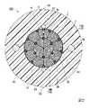
図1に示すように、光ファイバケーブル100は、複数の光ファイバユニット10を有するコア20と、コア20を内部に収容するシース55と、シース55に埋設された一対の抗張力体56(テンションメンバ)および一対の線条体57と、を備えている。コア20は、複数の光ファイバユニット10を包む押さえ巻き54を有している。Hereinafter, the optical fiber cable of this embodiment will be described with reference to the drawings.
As shown in FIG. 1, the
(方向定義)
本実施形態では、光ファイバケーブル100の中心軸線をケーブル中心軸Oという。また、ケーブル中心軸Oに沿う方向を長手方向という。ケーブル中心軸Oに直交する断面を横断面という。横断面視(図1)において、ケーブル中心軸Oに交差する方向を径方向といい、ケーブル中心軸O周りに周回する方向を周方向という。
なお、横断面視において、光ファイバケーブル100が非円形である場合には、光ファイバケーブル100の図心にケーブル中心軸Oが位置する。(Direction definition)
In the present embodiment, the central axis of the
When the
シース55は、ケーブル中心軸Oを中心とした円筒状に形成されている。シース55の材質としては、ポリエチレン(PE)、ポリプロピレン(PP)、エチレンエチルアクリレート共重合体(EEA)、エチレン酢酸ビニル共重合体(EVA)、エチレンプロピレン共重合体(EP)などのポリオレフィン(PO)樹脂、ポリ塩化ビニル(PVC)などを用いることができる。 The
線条体57の材質としては、PPやナイロン製の円柱状ロッドなどを用いることができる。また、PPやポリエステルなどの繊維を撚り合わせた糸(ヤーン)により線条体57を形成し、線条体57に吸水性を持たせてもよい。
一対の線条体57は、コア20を径方向で挟むように配置されている。各線条体57は、コア20の外周面(押さえ巻き54の外周面)に接している。なお、シース55に埋設される線条体57の数は、1または3以上であってもよい。As the material of the
The pair of striatum 57s are arranged so as to sandwich the
抗張力体56の材質としては、例えば金属線(鋼線など)、抗張力繊維(アラミド繊維など)、およびFRPなどを用いることができる。
一対の抗張力体56は、コア20を径方向で挟んで配置されている。また、一対の抗張力体56は、コア20から径方向に間隔をあけて配置されている。なお、シース55に埋設される抗張力体56の数は、1または3以上であってもよい。また、抗張力体56をシース55に埋設しなくてもよい。As the material of the
The pair of
シース55の外周面には、長手方向に沿って延びる一対の突起58が形成されている。突起58と線条体57とは、周方向において同等の位置に配置されている。なお、突起58は、線条体57を取り出すためにシース55を切開する際の目印となる。突起58に代えて、例えばシース55の一部の色を他の部位と異ならせることで、線条体57の位置を示す目印を設けてもよい。 A pair of
コア20は、複数の光ファイバユニット10と、複数の介在物3a~3cと、光ファイバユニット10および介在物3a~3cを包む押さえ巻き54と、を備えている。光ファイバユニット10はそれぞれ、複数の光ファイバ心線若しくは光ファイバ素線(以下、単に光ファイバ1という)と、光ファイバ1を束ねる結束材2と、を有している。光ファイバユニット10および介在物3a~3cは、長手方向に沿って延びている。 The
本実施形態の光ファイバユニット10は、いわゆる間欠接着型テープ心線であり、複数の光ファイバ1を長手方向に直交する方向に引っ張ると、網目状(蜘蛛の巣状)に広がるように互いに接着されている。詳しくは、ある一つの光ファイバ1が、その両隣の光ファイバ1に対して長手方向で異なる位置においてそれぞれ接着されており、かつ、隣接する光ファイバ1同士は、長手方向で一定の間隔をあけて互いに接着されている。
なお、光ファイバユニット10の態様は間欠接着型テープ心線に限られず、適宜変更してもよい。例えば、光ファイバユニット10は、複数の光ファイバ1を単に結束材2で束ねたものであってもよい。The
The mode of the
図1に示すように、光ファイバユニット10は、径方向内側の層および径方向外側の層の二層に分けられて配置されている。以下、最外層に位置する光ファイバユニット10を外側ユニット10Aという。また、外側ユニット10A以外の光ファイバユニット10を、内側ユニット10Bという。つまり、外側ユニット10Aおよび内側ユニット10Bは、複数の光ファイバユニット10に含まれている。 As shown in FIG. 1, the
図1の例では、3つの内側ユニット10Bが、ケーブル中心軸Oを中心として互いにSZ状または螺旋状に撚り合わされている。また、9つの外側ユニット10Aが、3つの内側ユニット10Bを囲むように、ケーブル中心軸Oを中心としてSZ状に撚り合わされている。なお、光ファイバユニット10の数は適宜変更可能である。 In the example of FIG. 1, the three
横断面視において、内層に位置する内側ユニット10Bは扇形に形成され、最外層に位置する外側ユニット10Aは四角形に形成されている。図示の例に限られず、断面が円形、楕円形、若しくは多角形の光ファイバユニット10を用いても良い。また、光ファイバユニット10の断面形状が崩れていてもよい。また、内側ユニット10Bが無く、1つの層(外側ユニット10Aの層)でコア20が構成されていてもよい。 In the cross-sectional view, the
結束材2は、細長い紐状であり、複数の光ファイバ1の周囲に巻き付けられている。光ファイバ1は、部分的に結束材2の隙間から露出している。このため、シース55を切開して押さえ巻き54を除去すると、結束材2の隙間から、光ファイバ1を視認可能となっている。結束材2は、薄く可撓性に富む樹脂などの材質により形成されている。このため、光ファイバ1は、結束材2で束ねられた状態であっても、この結束材2を変形させながらシース55内の空いている空間に適宜移動する。従って、実際の製品における光ファイバユニット10の断面形状は、図1のように整っていない場合がある。 The
押さえ巻き54は、ケーブル中心軸Oを中心とした円筒状に形成されている。押さえ巻き54の内周面は、外側ユニット10Aの径方向外側の端部に接している。また、押さえ巻き54の内周面は、介在物3b、3cに接している。押さえ巻き54としては、不織布やプラスチック製のテープ部材などを用いることができる。押さえ巻き54は、例えば吸水テープなどの吸水性を有する材質により形成されていてもよい。 The presser winding 54 is formed in a cylindrical shape centered on the cable center axis O. The inner peripheral surface of the
介在物3a~3cは、ポリエステル繊維、アラミド繊維、ガラス繊維などからなる繊維状の材質により形成されている。なお、介在物3a~3cは、吸水性を有するヤーンなどであってもよい。この場合、光ファイバケーブル100の内部の防水性能を高めることができる。 The
横断面視において、介在物3aは、外側ユニット10Aと内側ユニット10Bとの間に挟まれている。介在物3bは、周方向で隣り合う外側ユニット10A同士の間に挟まれるとともに、押さえ巻き54に接している。介在物3cは、1つの外側ユニット10Aと押さえ巻き54との間に挟まれている。介在物3aは、内側ユニット10Bとともに撚り合わされている。介在物3b、3cは、外側ユニット10Aとともに撚り合わされている。 In cross-sectional view, the
介在物3b、3cは、外側ユニット10Aに接している。介在物3aは、外側ユニット10Aおよび内側ユニット10Bに接している。ここで、結束材2は細長い紐状であり、例えば螺旋状に光ファイバ1の束に巻かれている。このため、光ファイバ1のうち、紐状の結束材2に覆われていない部分は、部分的に介在物3a~3cに接触する。 The
光ファイバ1は通常、ガラスにより形成された光ファイバ裸線の周囲に、樹脂などの被覆材がコーティングされた構造となっている。このため、光ファイバ1の表面は平滑であり、光ファイバ1同士が接触した際の摩擦係数は比較的小さい。これに対して、介在物3a~3cは繊維状の材質により形成されている。このため、介在物3a~3cと光ファイバ1とが接触した際の摩擦係数は、光ファイバ1同士が接触した際の摩擦係数よりも大きい。 The
以上のことから、複数の光ファイバユニット10に挟まれるように介在物3a~3cを配置することで、これら光ファイバユニット10同士が相対移動する際の摩擦抵抗を大きくすることができる。これにより、光ファイバケーブル100内における光ファイバユニット10の移動を抑制することが可能となる。 From the above, by arranging the
ところで、複数の光ファイバユニット10は、ケーブル中心軸Oを中心として互いに撚り合わされている。光ファイバユニット10が撚り戻ろうとした場合、光ファイバユニット10の束は径方向外側に膨らもうとする。つまり、撚り戻ろうとする力によって、外側ユニット10Aが押さえ巻き54に押し付けられる。ここで本実施形態では、横断面視において、外側ユニット10Aと押さえ巻き54との間に介在物3cが挟まれている。 By the way, the plurality of
この構成によれば、光ファイバユニット10の束が径方向外側に膨らもうとしたとき、外側ユニット10Aと押さえ巻き54との間で介在物3cが径方向に圧縮される。そして、介在物3cは繊維状の材質により形成されているため、光ファイバ1と押さえ巻き54との間の摩擦係数よりも、光ファイバ1と介在物3cとの間、および介在物3cと押さえ巻き54との間の摩擦係数の方が大きい。したがって、外側ユニット10Aが押さえ巻き54に直接的に押し付けられたときに生じる摩擦力よりも、外側ユニット10Aが介在物3cを挟んで押さえ巻き54に押し付けられたときに生じる摩擦力のほうが大きくなる。つまり本実施形態では、外側ユニット10Aが径方向外側に膨らもうとしたとき、介在物3cが大きな摩擦力を生じさせる。この摩擦力により、外側ユニット10Aが押さえ巻き54に対して移動しにくくなり、外側ユニット10Aの撚り戻りを抑制することが可能となっている。 According to this configuration, when the bundle of the
また、本実施形態では、横断面視において、外側ユニット10Aの中心点Aと、ケーブル中心軸Oとを通る直線L上に、介在物3cが位置している。この構成により、外側ユニット10Aが径方向外側に向けて膨らもうとする力を、より効率よく摩擦力に変換することができる。したがって、より確実に外側ユニット10Aの撚り戻りを抑制することができる。 Further, in the present embodiment, the
また本実施形態では、横断面視において、介在物3cが1つの外側ユニット10Aおよび押さえ巻き54によって囲まれている。このため、光ファイバユニット10の束が径方向外側に膨らもうとしたときに、介在物3cがより確実に外側ユニット10Aと押さえ巻き54との間で挟まれる。したがって、介在物3cによる摩擦力をより確実に生じさせて、撚り戻りを抑制することができる。 Further, in the present embodiment, in the cross-sectional view, the
なお、本明細書における中心点Aとは、横断面視における外側ユニット10Aの図心である。外側ユニット10Aは、ケーブル中心軸Oを中心として撚り合わされているため、撚り戻りによって外側ユニット10Aは径方向外側に向けて膨らもうとする。そして、外側ユニット10Aが膨らむ方向は、ケーブル中心軸Oを起点として、中心点A(外側ユニット10Aの図心)を通る方向となる。したがって、ケーブル中心軸Oおよび中心点Aを通る直線L上に介在物3cを位置させることで、外側ユニット10Aが膨らもうとする力を起因として介在物3cが生じさせる摩擦力が大きくなり、有効に撚り戻りを抑制することができる。 The center point A in the present specification is the center of gravity of the
以下、具体的な実施例を用いて、上記実施形態を説明する。なお、本発明は以下の実施例に限定されない。 Hereinafter, the above embodiment will be described with reference to specific examples. The present invention is not limited to the following examples.
(実施例1)
実施例1として、図1に示すような断面構造を有する光ファイバケーブルを作成した。光ファイバユニット10に含まれる光ファイバ1の数は、144本とした。3本の内側ユニット10BをSZ状に撚り合わせ、その外周に9本の外側ユニット10AをSZ状に撚り合わせた。すなわち、光ファイバユニット10の数は合計で12であり、光ファイバ1の数は合計で1728である。介在物3a、3b、3cとして、吸水性のヤーンを用いた。介在物3aを3本、介在物3bを8本、介在物3cを1本配置した。(Example 1)
As Example 1, an optical fiber cable having a cross-sectional structure as shown in FIG. 1 was produced. The number of
光ファイバユニット10を撚り合わせる際の撚り合わせ装置(オシレータ)の設定角度は、実際に導入される撚りの角度(導入角度)が±150°となるように調整した。なお、「設定角度」とは、オシレータを揺動させる角度の範囲である。例えば設定角度が±500°の場合、オシレータはCW方向に500°揺動した後、CCW方向に500°揺動する動作を繰り返す。 The setting angle of the twisting device (oscillator) when twisting the
導入角度は、ケーブル化後に、光ファイバケーブルを長手方向に所定の間隔を空けて切断し、特定の外側ユニット10Aまたは当該外側ユニット10Aに含まれる光ファイバ1の各切断面における位置を確認することで測定する。設定角度と導入角度との差が大きいほど、外側ユニット10Aが大きく撚り戻りしていることを意味する。
撚り合わされた光ファイバユニット10を押さえ巻き54で包み、さらにシース55で被覆することで光ファイバケーブルを作成する。As for the introduction angle, after the cable is formed, the optical fiber cable is cut at a predetermined interval in the longitudinal direction, and the position on each cut surface of the specific
An optical fiber cable is made by wrapping the twisted
(実施例2)
実施例2として、介在物3b、3cの数を実施例1から変更した光ファイバケーブルを作成した。介在物3aを3本、介在物3bを6本、介在物3cを3本配置した。その他の条件は実施例1と同様である。(Example 2)
As the second embodiment, an optical fiber cable in which the number of
(実施例3)
実施例3として、介在物3a、3b、3cの数を実施例1から変更した光ファイバケーブルを作成した。介在物3a、3bを配置せず、介在物3cのみを6本配置した。その他の条件は実施例1と同様である。(Example 3)
As the third embodiment, an optical fiber cable in which the number of
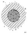
(実施例4)
実施例4として、介在物3a、3b、3cの数を実施例1から変更した光ファイバケーブルを作成した。介在物3aを配置せず、介在物3bを6本、介在物3cを3本配置した。さらに、図2に示すような介在物3dを3本配置した。介在物3dは、径方向で内側ユニット10Bと外側ユニットAとの間に挟まれている。その他の条件は実施例1と同様である。(Example 4)
As Example 4, an optical fiber cable in which the number of
(実施例5)
実施例5として、介在物3a、3b、3cの数を実施例1から変更した光ファイバケーブルを作成した。介在物3bを配置せず、介在物3aを3本、介在物3cを9本配置した。その他の条件は実施例1と同様である。(Example 5)
As Example 5, an optical fiber cable in which the number of
(比較例1)
比較例1として、介在物3cを設けず、介在物3a、3bを設けた光ファイバケーブル100を作成した。介在物3aを3本、介在物3bを9本配置した。その他の条件は実施例1と同様とした。(Comparative Example 1)
As Comparative Example 1, an
実施例1~5および比較例1の光ファイバケーブルについて、導入角度およびシースねじれを確認した結果を表1に示す。 Table 1 shows the results of confirming the introduction angle and sheath twist of the optical fiber cables of Examples 1 to 5 and Comparative Example 1.

表1の「シースねじれ」とは、作成された光ファイバケーブルにおけるシースのねじれの程度を表している。より詳しくは、突起58の周方向における位置が、長手方向に沿ってどの程度変化しているかを示している。例えばシースねじれが±10°の場合、突起58の周方向の位置が、ケーブル中心軸Oを中心として±10°の範囲で変化している。シースねじれの程度が大きいと、光ファイバケーブルが蛇行してしまい、敷設の作業性低下やドラムへの巻き付け可能な長さの減少につながる。 The “sheath twist” in Table 1 indicates the degree of sheath twist in the produced optical fiber cable. More specifically, it shows how much the position of the
「判定」欄は、シースねじれが±10°以下の場合に結果が良好(OK)とし、シースねじれが±10°を超えた場合に結果が不十分(NG)とした。なお、シースねじれは、設定角度が大きいほど大きくなる。これは、設定角度が大きいほど、撚り合わされた光ファイバユニット10が強く撚り戻ろうとして、シース55をケーブル中心軸O回りに捻回させてしまうためである。 In the "judgment" column, the result was good (OK) when the sheath twist was ± 10 ° or less, and the result was insufficient (NG) when the sheath twist exceeded ± 10 °. The sheath twist increases as the set angle increases. This is because the larger the set angle, the stronger the twisted
表1に示す通り、実施例1~5ではシースねじれが±10°以下となり、良好な結果が得られた。一方、介在物3cを配置しなかった比較例1では、シースねじれが±45°となり、結果が不十分となった。 As shown in Table 1, in Examples 1 to 5, the sheath twist was ± 10 ° or less, and good results were obtained. On the other hand, in Comparative Example 1 in which the
実施例1~5で良好な結果が得られた理由として、導入角度を±150°とするための設定角度が±500°以下であり、比較的小さいことが考えられる。そして、このように設定角度を小さくすることができた原因は、介在物3cによって、外側ユニット10Aの撚り戻りを低減できたためである。つまり、外側ユニット10Aを含む光ファイバユニット10が撚り戻ろうとして径方向外側に膨らもうとしたときに、外側ユニット10Aと押さえ巻き54との間に介在物3cが挟まれて摩擦力を生じさせたことによる。 The reason why good results were obtained in Examples 1 to 5 is that the set angle for setting the introduction angle to ± 150 ° is ± 500 ° or less, which is considered to be relatively small. The reason why the set angle could be reduced in this way is that the
一方、比較例1では介在物3cが設けられていないため、光ファイバユニット10が撚り戻ろうとしたときに、外側ユニット10Aと押さえ巻き54との間に生じる摩擦力が比較的小さくなる。このため、撚り戻りが生じやすくなり、導入角度を±150°とするための設定角度が±700°となり、比較的大きくなった。そして、設定角度が大きいほど、外側ユニット10Aがシース55を捻回させる力も強くなるため、シースねじれの数値が大きくなってしまったと考えられる。 On the other hand, in Comparative Example 1, since the
以上の結果から、ケーブル中心軸Oと外側ユニット10Aとを通る直線L上に少なくとも1つの介在物3cを設けることで、外側ユニット10Aの撚り戻りを低減できることが確認された。また、外側ユニット10Aの撚り戻りが低減される結果、設定角度を小さくすることが可能となり、シース55に生じるねじれも抑制できることが判った。 From the above results, it was confirmed that the untwisting of the
また、実施例2と実施例5とを比較すると、押さえ巻き54に接する介在物3b、3cの合計本数は同じであるが、導入角度を±150°とするための設定角度については、実施例5の方が小さくなっている。つまり、実施例5の方が実施例2よりも効果的に撚り戻りを抑制している。これは、介在物3cが、ケーブル中心軸Oおよび外側ユニット10Aの中心点を通る直線上に位置していることで、外側ユニット10Aが径方向外側に膨らもうとする力を有効に摩擦力に変換できたためであると考えられる。 Further, when the second embodiment and the fifth embodiment are compared, the total number of
また、実施例3では、他の実施例1、2、4、5と比較して、介在物の合計本数が少なくても良好な結果が得られた。そして、実施例3は、介在物3cのみを配置している。この結果から、介在物3cによる撚り戻りの抑止効果が、他の介在物よりも大きいことが確認できた。 Further, in Example 3, good results were obtained even if the total number of inclusions was small as compared with the other Examples 1, 2, 4, and 5. And in Example 3, only inclusions 3c are arranged. From this result, it was confirmed that the effect of suppressing untwisting by the
なお、本発明の技術的範囲は前記実施の形態に限定されず、本発明の趣旨を逸脱しない範囲において種々の変更を加えることが可能である。 The technical scope of the present invention is not limited to the above-described embodiment, and various modifications can be made without departing from the spirit of the present invention.
例えば図1の例では、コア20に2層の光ファイバユニット10が含まれていた。しかしながら、コア20に含まれる光ファイバユニットの層の数は、1でもよいし、3以上であってもよい。
また、コア20に光ファイバユニットの層が複数含まれる場合、最外層以外の層に含まれる光ファイバユニット(図1の例では内側ユニット10B)同士の間には介在物が配置されていなくてもよい。For example, in the example of FIG. 1, the
Further, when the
また、前記実施形態では、介在物3cが1つの外側ユニット10Aと押さえ巻き54との間に挟まれていた。しかしながら、図3に示すように、介在物3cが複数の外側ユニット10Aと押さえ巻き54との間に挟まれていてもよい。この場合であっても、外側ユニット10Aが径方向外側に向けて膨らもうとする力を用いて、外側ユニット10Aと介在物3cとの間、および介在物3cと押さえ巻き54との間に摩擦力を生じさせることができる。また、介在物3cが、ケーブル中心軸Oと外側ユニット10Aの中心点Aとを通る直線L上に位置していることで、外側ユニット10Aが径方向外側に向けて膨らもうとする力を、より効率よく摩擦力へと変換することができる。したがって、より確実に外側ユニット10Aの撚り戻りを抑制することができる。 Further, in the above embodiment, the
その他、本発明の趣旨を逸脱しない範囲で、上記した実施の形態における構成要素を周知の構成要素に置き換えることは適宜可能であり、また、上記した実施形態や変形例を適宜組み合わせてもよい。 In addition, it is possible to appropriately replace the components in the above-described embodiment with well-known components without departing from the spirit of the present invention, and the above-described embodiments and modifications may be appropriately combined.
1…光ファイバ 2…結束材 3a~3c…介在物 10…光ファイバユニット 10A…外側ユニット 20…コア 54…押さえ巻き 55…シース A…外側ユニットの中心点 L…直線 O…ケーブル中心軸 1 ...
Claims (3)
Translated fromJapanese前記複数の光ファイバユニットを包む押さえ巻きと、
前記押さえ巻きの内側に配置された少なくとも1つの介在物と、
前記押さえ巻きを被覆するシースと、を備え、
前記複数の光ファイバユニットのうち最外層に位置する複数の外側ユニットは、ケーブル中心軸を中心としてSZ状に撚り合わされ、
横断面視において、1つの前記外側ユニットの径方向外側の端部に形成された凹部の内側に前記介在物が位置し、前記凹部が形成された前記外側ユニットと前記押さえ巻きとの間に前記介在物が挟まれ、
横断面視において、前記凹部が形成された前記外側ユニットの中心点と、ケーブル中心軸とを通る直線上に、前記介在物が位置している、光ファイバケーブル。Multiple optical fiber units each having multiple optical fibers,
The presser winding that wraps the plurality of optical fiber units and
With at least one inclusions placed inside the presser roll,
With a sheath covering the presser foot,
The plurality of outer units located in the outermost layer of the plurality of optical fiber units are twisted in an SZ shape around the cable center axis.
In a cross-sectional view, the inclusions are located inside a recess formed at the radially outer end of one outer unit, and the recess is formed between the outer unit and the presser winding. The inclusions are pinched,
An optical fiber cablein which the inclusions are located on a straight line passing through the center point of the outer unit in which the recess is formed and the cable center axis in a cross-sectional view .
Priority Applications (14)
| Application Number | Priority Date | Filing Date | Title |
|---|---|---|---|
| JP2018194103AJP7068131B2 (en) | 2018-10-15 | 2018-10-15 | Fiber optic cable |
| EP23151116.3AEP4184229A1 (en) | 2018-09-11 | 2019-09-03 | Optical fiber cable |
| CN202310297660.XACN116299922A (en) | 2018-09-11 | 2019-09-03 | optic fibre cable |
| CA3106482ACA3106482C (en) | 2018-09-11 | 2019-09-03 | Optical fiber cable |
| EP19859562.1AEP3800492B1 (en) | 2018-09-11 | 2019-09-03 | Optical fiber cable |
| CN201980043925.5ACN112400130B (en) | 2018-09-11 | 2019-09-03 | Optical fiber cable |
| CN202310297870.9ACN116299923A (en) | 2018-09-11 | 2019-09-03 | optic fibre cable |
| ES19859562TES2942891T3 (en) | 2018-09-11 | 2019-09-03 | fiber optic cable |
| CA3205489ACA3205489A1 (en) | 2018-09-11 | 2019-09-03 | Optical fiber cable |
| AU2019338756AAU2019338756B2 (en) | 2018-09-11 | 2019-09-03 | Optical fiber cable |
| PCT/JP2019/034515WO2020054493A1 (en) | 2018-09-11 | 2019-09-03 | Optical fiber cable |
| US17/260,792US11592634B2 (en) | 2018-09-11 | 2019-09-03 | Optical fiber cable |
| AU2022202391AAU2022202391B2 (en) | 2018-09-11 | 2022-04-11 | Optical fiber cable |
| US18/156,658US20230161125A1 (en) | 2018-09-11 | 2023-01-19 | Optical fiber cable |
Applications Claiming Priority (1)
| Application Number | Priority Date | Filing Date | Title |
|---|---|---|---|
| JP2018194103AJP7068131B2 (en) | 2018-10-15 | 2018-10-15 | Fiber optic cable |
Publications (2)
| Publication Number | Publication Date |
|---|---|
| JP2020064098A JP2020064098A (en) | 2020-04-23 |
| JP7068131B2true JP7068131B2 (en) | 2022-05-16 |
Family
ID=70387154
Family Applications (1)
| Application Number | Title | Priority Date | Filing Date |
|---|---|---|---|
| JP2018194103AActiveJP7068131B2 (en) | 2018-09-11 | 2018-10-15 | Fiber optic cable |
Country Status (1)
| Country | Link |
|---|---|
| JP (1) | JP7068131B2 (en) |
Families Citing this family (1)
| Publication number | Priority date | Publication date | Assignee | Title |
|---|---|---|---|---|
| CA3187777A1 (en) | 2020-09-02 | 2022-03-10 | Masatoshi Ohno | Optical cable and optical cable manufacturing method |
Citations (9)
| Publication number | Priority date | Publication date | Assignee | Title |
|---|---|---|---|---|
| JP2001051169A (en) | 1999-08-09 | 2001-02-23 | Sumitomo Electric Ind Ltd | Optical cable |
| JP2002107589A (en) | 2000-09-21 | 2002-04-10 | Alcatel | Improved fiber optic cable containing thermally coupled fiber optic buffer tube and method of making same |
| US20060072886A1 (en) | 2003-02-25 | 2006-04-06 | Tae-Gyoung Kim | Loose tube optical cable |
| JP2012083418A (en) | 2010-10-07 | 2012-04-26 | Sumitomo Electric Ind Ltd | Optical fiber cord |
| JP2014139609A (en) | 2013-01-21 | 2014-07-31 | Fujikura Ltd | Optical fiber cable |
| JP2015129837A (en) | 2014-01-07 | 2015-07-16 | 住友電気工業株式会社 | Optical cable and manufacturing method thereof |
| US20150370026A1 (en) | 2014-06-23 | 2015-12-24 | Corning Optical Communications LLC | Optical fiber cable |
| JP2018136376A (en) | 2017-02-20 | 2018-08-30 | 株式会社フジクラ | Optical fiber cable |
| WO2018174004A1 (en) | 2017-03-21 | 2018-09-27 | 住友電気工業株式会社 | Optical fiber cable |
Family Cites Families (4)
| Publication number | Priority date | Publication date | Assignee | Title |
|---|---|---|---|---|
| JPH09166733A (en)* | 1995-12-15 | 1997-06-24 | Fujikura Ltd | Fiber optic cable |
| JPH10170779A (en)* | 1996-12-11 | 1998-06-26 | Fujikura Ltd | Fiber optic cable |
| JPH1138284A (en)* | 1997-07-23 | 1999-02-12 | Ube Nitto Kasei Co Ltd | Fiber optic cable |
| US7382955B1 (en)* | 2007-01-09 | 2008-06-03 | Nexans | Optical fiber cable with system and method for mid-span access |
- 2018
- 2018-10-15JPJP2018194103Apatent/JP7068131B2/enactiveActive
Patent Citations (9)
| Publication number | Priority date | Publication date | Assignee | Title |
|---|---|---|---|---|
| JP2001051169A (en) | 1999-08-09 | 2001-02-23 | Sumitomo Electric Ind Ltd | Optical cable |
| JP2002107589A (en) | 2000-09-21 | 2002-04-10 | Alcatel | Improved fiber optic cable containing thermally coupled fiber optic buffer tube and method of making same |
| US20060072886A1 (en) | 2003-02-25 | 2006-04-06 | Tae-Gyoung Kim | Loose tube optical cable |
| JP2012083418A (en) | 2010-10-07 | 2012-04-26 | Sumitomo Electric Ind Ltd | Optical fiber cord |
| JP2014139609A (en) | 2013-01-21 | 2014-07-31 | Fujikura Ltd | Optical fiber cable |
| JP2015129837A (en) | 2014-01-07 | 2015-07-16 | 住友電気工業株式会社 | Optical cable and manufacturing method thereof |
| US20150370026A1 (en) | 2014-06-23 | 2015-12-24 | Corning Optical Communications LLC | Optical fiber cable |
| JP2018136376A (en) | 2017-02-20 | 2018-08-30 | 株式会社フジクラ | Optical fiber cable |
| WO2018174004A1 (en) | 2017-03-21 | 2018-09-27 | 住友電気工業株式会社 | Optical fiber cable |
Also Published As
| Publication number | Publication date |
|---|---|
| JP2020064098A (en) | 2020-04-23 |
Similar Documents
| Publication | Publication Date | Title |
|---|---|---|
| JP7307859B2 (en) | fiber optic cable | |
| JP2022100376A (en) | Fiber optic cable | |
| CA3051607C (en) | Optical fiber cable | |
| JP7479533B2 (en) | Slotless optical fiber cable and method for manufacturing slotless optical cable core | |
| US20230161125A1 (en) | Optical fiber cable | |
| JP7184526B2 (en) | fiber optic cable | |
| JP7068114B2 (en) | Fiber optic cable | |
| JP7068131B2 (en) | Fiber optic cable | |
| JP7126935B2 (en) | fiber optic cable | |
| JP6382387B1 (en) | Optical fiber cable manufacturing method and optical fiber cable manufacturing apparatus | |
| JP2020204685A (en) | Optical fiber cable | |
| JP7704583B2 (en) | Fiber optic cable | |
| JP7609982B2 (en) | Fiber optic cable | |
| JP2021196567A (en) | Optical fiber cable | |
| TW202334680A (en) | Optical fiber assembly, optical fiber cable, and method for manufacturing optical fiber assembly | |
| WO2025033318A1 (en) | Optical fiber cable | |
| JP2009080346A (en) | Optical cable |
Legal Events
| Date | Code | Title | Description |
|---|---|---|---|
| A521 | Request for written amendment filed | Free format text:JAPANESE INTERMEDIATE CODE: A523 Effective date:20200109 | |
| A621 | Written request for application examination | Free format text:JAPANESE INTERMEDIATE CODE: A621 Effective date:20200109 | |
| A131 | Notification of reasons for refusal | Free format text:JAPANESE INTERMEDIATE CODE: A131 Effective date:20210302 | |
| A521 | Request for written amendment filed | Free format text:JAPANESE INTERMEDIATE CODE: A523 Effective date:20210427 | |
| A131 | Notification of reasons for refusal | Free format text:JAPANESE INTERMEDIATE CODE: A131 Effective date:20211005 | |
| A521 | Request for written amendment filed | Free format text:JAPANESE INTERMEDIATE CODE: A523 Effective date:20211130 | |
| TRDD | Decision of grant or rejection written | ||
| A01 | Written decision to grant a patent or to grant a registration (utility model) | Free format text:JAPANESE INTERMEDIATE CODE: A01 Effective date:20220405 | |
| A61 | First payment of annual fees (during grant procedure) | Free format text:JAPANESE INTERMEDIATE CODE: A61 Effective date:20220428 | |
| R151 | Written notification of patent or utility model registration | Ref document number:7068131 Country of ref document:JP Free format text:JAPANESE INTERMEDIATE CODE: R151 | |
| R250 | Receipt of annual fees | Free format text:JAPANESE INTERMEDIATE CODE: R250 |