JP7067195B2 - Electronic devices, illuminance detection methods, and illuminance detection programs - Google Patents
Electronic devices, illuminance detection methods, and illuminance detection programsDownload PDFInfo
- Publication number
- JP7067195B2 JP7067195B2JP2018064733AJP2018064733AJP7067195B2JP 7067195 B2JP7067195 B2JP 7067195B2JP 2018064733 AJP2018064733 AJP 2018064733AJP 2018064733 AJP2018064733 AJP 2018064733AJP 7067195 B2JP7067195 B2JP 7067195B2
- Authority
- JP
- Japan
- Prior art keywords
- illuminance
- display means
- display
- cpu
- display unit
- Prior art date
- Legal status (The legal status is an assumption and is not a legal conclusion. Google has not performed a legal analysis and makes no representation as to the accuracy of the status listed.)
- Active
Links
Images


Classifications
- G—PHYSICS
- G04—HOROLOGY
- G04G—ELECTRONIC TIME-PIECES
- G04G21/00—Input or output devices integrated in time-pieces
- G04G21/02—Detectors of external physical values, e.g. temperature
- G—PHYSICS
- G06—COMPUTING OR CALCULATING; COUNTING
- G06F—ELECTRIC DIGITAL DATA PROCESSING
- G06F3/00—Input arrangements for transferring data to be processed into a form capable of being handled by the computer; Output arrangements for transferring data from processing unit to output unit, e.g. interface arrangements
- G06F3/14—Digital output to display device ; Cooperation and interconnection of the display device with other functional units
- G06F3/1423—Digital output to display device ; Cooperation and interconnection of the display device with other functional units controlling a plurality of local displays, e.g. CRT and flat panel display
- G—PHYSICS
- G09—EDUCATION; CRYPTOGRAPHY; DISPLAY; ADVERTISING; SEALS
- G09G—ARRANGEMENTS OR CIRCUITS FOR CONTROL OF INDICATING DEVICES USING STATIC MEANS TO PRESENT VARIABLE INFORMATION
- G09G3/00—Control arrangements or circuits, of interest only in connection with visual indicators other than cathode-ray tubes
- G09G3/20—Control arrangements or circuits, of interest only in connection with visual indicators other than cathode-ray tubes for presentation of an assembly of a number of characters, e.g. a page, by composing the assembly by combination of individual elements arranged in a matrix no fixed position being assigned to or needed to be assigned to the individual characters or partial characters
- G—PHYSICS
- G09—EDUCATION; CRYPTOGRAPHY; DISPLAY; ADVERTISING; SEALS
- G09G—ARRANGEMENTS OR CIRCUITS FOR CONTROL OF INDICATING DEVICES USING STATIC MEANS TO PRESENT VARIABLE INFORMATION
- G09G5/00—Control arrangements or circuits for visual indicators common to cathode-ray tube indicators and other visual indicators
- G09G5/10—Intensity circuits
- G—PHYSICS
- G04—HOROLOGY
- G04G—ELECTRONIC TIME-PIECES
- G04G21/00—Input or output devices integrated in time-pieces
- G04G21/08—Touch switches specially adapted for time-pieces
- G—PHYSICS
- G04—HOROLOGY
- G04G—ELECTRONIC TIME-PIECES
- G04G9/00—Visual time or date indication means
- G04G9/0017—Visual time or date indication means in which the light emitting display elements may be activated at will or are controlled in accordance with the ambient light
- G—PHYSICS
- G09—EDUCATION; CRYPTOGRAPHY; DISPLAY; ADVERTISING; SEALS
- G09G—ARRANGEMENTS OR CIRCUITS FOR CONTROL OF INDICATING DEVICES USING STATIC MEANS TO PRESENT VARIABLE INFORMATION
- G09G2300/00—Aspects of the constitution of display devices
- G09G2300/02—Composition of display devices
- G09G2300/023—Display panel composed of stacked panels
- G—PHYSICS
- G09—EDUCATION; CRYPTOGRAPHY; DISPLAY; ADVERTISING; SEALS
- G09G—ARRANGEMENTS OR CIRCUITS FOR CONTROL OF INDICATING DEVICES USING STATIC MEANS TO PRESENT VARIABLE INFORMATION
- G09G2320/00—Control of display operating conditions
- G09G2320/06—Adjustment of display parameters
- G09G2320/0626—Adjustment of display parameters for control of overall brightness
- G—PHYSICS
- G09—EDUCATION; CRYPTOGRAPHY; DISPLAY; ADVERTISING; SEALS
- G09G—ARRANGEMENTS OR CIRCUITS FOR CONTROL OF INDICATING DEVICES USING STATIC MEANS TO PRESENT VARIABLE INFORMATION
- G09G2354/00—Aspects of interface with display user
- G—PHYSICS
- G09—EDUCATION; CRYPTOGRAPHY; DISPLAY; ADVERTISING; SEALS
- G09G—ARRANGEMENTS OR CIRCUITS FOR CONTROL OF INDICATING DEVICES USING STATIC MEANS TO PRESENT VARIABLE INFORMATION
- G09G2360/00—Aspects of the architecture of display systems
- G09G2360/14—Detecting light within display terminals, e.g. using a single or a plurality of photosensors
- G09G2360/144—Detecting light within display terminals, e.g. using a single or a plurality of photosensors the light being ambient light
- G—PHYSICS
- G09—EDUCATION; CRYPTOGRAPHY; DISPLAY; ADVERTISING; SEALS
- G09G—ARRANGEMENTS OR CIRCUITS FOR CONTROL OF INDICATING DEVICES USING STATIC MEANS TO PRESENT VARIABLE INFORMATION
- G09G3/00—Control arrangements or circuits, of interest only in connection with visual indicators other than cathode-ray tubes
- G09G3/20—Control arrangements or circuits, of interest only in connection with visual indicators other than cathode-ray tubes for presentation of an assembly of a number of characters, e.g. a page, by composing the assembly by combination of individual elements arranged in a matrix no fixed position being assigned to or needed to be assigned to the individual characters or partial characters
- G09G3/22—Control arrangements or circuits, of interest only in connection with visual indicators other than cathode-ray tubes for presentation of an assembly of a number of characters, e.g. a page, by composing the assembly by combination of individual elements arranged in a matrix no fixed position being assigned to or needed to be assigned to the individual characters or partial characters using controlled light sources
- G09G3/30—Control arrangements or circuits, of interest only in connection with visual indicators other than cathode-ray tubes for presentation of an assembly of a number of characters, e.g. a page, by composing the assembly by combination of individual elements arranged in a matrix no fixed position being assigned to or needed to be assigned to the individual characters or partial characters using controlled light sources using electroluminescent panels
- G09G3/32—Control arrangements or circuits, of interest only in connection with visual indicators other than cathode-ray tubes for presentation of an assembly of a number of characters, e.g. a page, by composing the assembly by combination of individual elements arranged in a matrix no fixed position being assigned to or needed to be assigned to the individual characters or partial characters using controlled light sources using electroluminescent panels semiconductive, e.g. using light-emitting diodes [LED]
- G09G3/3208—Control arrangements or circuits, of interest only in connection with visual indicators other than cathode-ray tubes for presentation of an assembly of a number of characters, e.g. a page, by composing the assembly by combination of individual elements arranged in a matrix no fixed position being assigned to or needed to be assigned to the individual characters or partial characters using controlled light sources using electroluminescent panels semiconductive, e.g. using light-emitting diodes [LED] organic, e.g. using organic light-emitting diodes [OLED]
- G—PHYSICS
- G09—EDUCATION; CRYPTOGRAPHY; DISPLAY; ADVERTISING; SEALS
- G09G—ARRANGEMENTS OR CIRCUITS FOR CONTROL OF INDICATING DEVICES USING STATIC MEANS TO PRESENT VARIABLE INFORMATION
- G09G3/00—Control arrangements or circuits, of interest only in connection with visual indicators other than cathode-ray tubes
- G09G3/20—Control arrangements or circuits, of interest only in connection with visual indicators other than cathode-ray tubes for presentation of an assembly of a number of characters, e.g. a page, by composing the assembly by combination of individual elements arranged in a matrix no fixed position being assigned to or needed to be assigned to the individual characters or partial characters
- G09G3/34—Control arrangements or circuits, of interest only in connection with visual indicators other than cathode-ray tubes for presentation of an assembly of a number of characters, e.g. a page, by composing the assembly by combination of individual elements arranged in a matrix no fixed position being assigned to or needed to be assigned to the individual characters or partial characters by control of light from an independent source
- G09G3/36—Control arrangements or circuits, of interest only in connection with visual indicators other than cathode-ray tubes for presentation of an assembly of a number of characters, e.g. a page, by composing the assembly by combination of individual elements arranged in a matrix no fixed position being assigned to or needed to be assigned to the individual characters or partial characters by control of light from an independent source using liquid crystals
Landscapes
- Engineering & Computer Science (AREA)
- Physics & Mathematics (AREA)
- General Physics & Mathematics (AREA)
- Theoretical Computer Science (AREA)
- Computer Hardware Design (AREA)
- Microelectronics & Electronic Packaging (AREA)
- Human Computer Interaction (AREA)
- General Engineering & Computer Science (AREA)
- Controls And Circuits For Display Device (AREA)
- Control Of Indicators Other Than Cathode Ray Tubes (AREA)
- Indication In Cameras, And Counting Of Exposures (AREA)
- Circuit Arrangement For Electric Light Sources In General (AREA)
- Photometry And Measurement Of Optical Pulse Characteristics (AREA)
- Control Of El Displays (AREA)
- Liquid Crystal Display Device Control (AREA)
- Electric Clocks (AREA)
Description
Translated fromJapanese本発明は、電子機器、照度検出方法、及び照度検出プログラムに関する。 The present invention relates to electronic devices, illuminance detection methods, and illuminance detection programs.
表示部であるOLED(Organic Light Emitting Diode)の視認側とは背面側に照度センサを配置し、その照度センサによる外光の検出値に応じて、光量の調整を行う技術が知られている。 There is known a technique of arranging an illuminance sensor on the back side of an OLED (Organic Light Emitting Diode) which is a display unit and adjusting the amount of light according to the detection value of external light by the illuminance sensor.
しかしながら、上記のような従来技術では、表示部の発光レベル(例えば輝度)が比較的高くかつ外光の照度が比較的低くなるにつれて、照度センサの検出値に対する表示部からの光の寄与が大きくなり、外光の照度に応じて行う制御の信頼性を高めることが難しくなる。 However, in the above-mentioned conventional technique, as the emission level (for example, brightness) of the display unit is relatively high and the illuminance of the external light is relatively low, the contribution of the light from the display unit to the detection value of the illuminance sensor becomes large. Therefore, it becomes difficult to improve the reliability of the control performed according to the illuminance of the external light.
そこで、1つの側面では、本発明は、外光の照度に応じて行う制御の信頼性を高めることを目的とする。 Therefore, in one aspect, it is an object of the present invention to improve the reliability of the control performed according to the illuminance of the external light.
上記目的を達成するために、本発明の1つの側面では、
表示手段と、
前記表示手段の表示面の背面側に配置され、表示手段からの光と表示手段を透過した外光とを検出する照度検出手段と、
前記表示手段の発光レベルが第1閾値以上である第1状態で前記照度検出手段により検出された照度が所定照度未満の場合、前記表示手段の発光レベルを、前記第1閾値よりも小さい所定レベル以下に低減した第2状態で前記照度検出手段により照度を検出させる制御手段と、
を備え、
前記所定照度は、前記表示手段の発光レベルが大きいほど低くなる態様で、前記表示手段の発光レベルに応じて変化する
ことを特徴とする電子機器が提供される。
In order to achieve the above object, in one aspect of the invention,
Display means and
An illuminance detecting means, which is arranged on the back side of the display surface ofthe display means and detects the light from the display means and the external light transmitted through the display means .
When the illuminance detected by the illuminance detecting means is less than the predetermined illuminance in the first state where the light emitting level of the display means is equal to or higher than the first threshold value, the light emitting level of the display means is set to a predetermined level smaller than the first threshold value. The control means for detecting the illuminance by the illuminance detecting means in the second state reduced below,
Equippedwith
The predetermined illuminance changes according to the light emission level of the display means in such a manner that the higher the light emission level of the display means is, the lower the illuminance is.
Electronic devices characterized by this are provided.
1つの側面では、本発明によれば、表示部の発光レベルが比較的高くかつ外光の照度が比較的低い場合に、外光の照度に応じて行う制御の信頼性を高めることが可能となる。 On one aspect, according to the present invention, it is possible to increase the reliability of the control performed according to the illuminance of the external light when the emission level of the display unit is relatively high and the illuminance of the external light is relatively low. Become.
以下、添付図面を参照しながら各実施例について詳細に説明する。 Hereinafter, each embodiment will be described in detail with reference to the accompanying drawings.
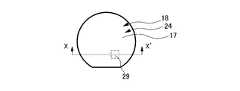
図1は、本発明の一実施例である電子機器1の概略図である。図1に示すように、本実施例の電子機器1は、腕時計型の装置(スマートウォッチ等)として構成されている。また、電子機器1は、第1表示部18及び第2表示部24(後述)を備えており、第1表示部18の上に第2表示部24が積層されている。さらに、第2表示部24の上には、後述するタッチパネル17が設けられている。このため、電子機器1においては、第1表示部18の表示に第2表示部24の表示を重ね合わせて表示することが可能であるとともに、表示内容にタッチ操作することが可能となっている。 FIG. 1 is a schematic view of an
図2は、電子機器1のハードウェア構成を示すブロック図である。図2に示すように、電子機器1は、CPU(Central Processing Unit)11と、ROM(Read Only Memory)12と、RAM(Random Access Memory)13と、記憶部14と、RTC(Real Time Clock)部15と、ドライブ16と、タッチパネル17と、第1表示部18(表示手段の一例)と、第1入力部19と、ブルートゥース(登録商標)用アンテナ20と、ブルートゥースモジュール21と、無線LAN(Local Area Network)アンテナ22と、無線LANモジュール23と、第2表示部24と、脈拍センサ25と、地磁気センサ26と、加速度センサ27と、ジャイロセンサ28と、照度センサ29(照度検出手段の一例)と、第2入力部30と、GPS(Global Positioning System)アンテナ31と、GPSモジュール32と、を備えている。 FIG. 2 is a block diagram showing a hardware configuration of the
CPU11は、第1CPU11Aと、第2CPU11Bとによって構成される。第1CPU11Aは、各種演算処理を行い、OS(Operating System)の処理を実行することにより、電子機器1におけるスマートフォンに類する機能を制御する。本実施例において、第1CPU11Aは、ブルートゥースモジュール21あるいは無線LANモジュール23を介して受信した電子メールの着信や気象情報に関するメッセージ等を第1表示部18に表示させたり、タッチパネル17を介して入力される操作を受け付けたりする。また、第1CPU11Aは、第1入力部19を介して入力される音声を認識したり、その他、スマートフォンに類する機能として実装された各種機能に係る処理を行ったりする。 The
また、本実施例において、第1CPU11Aは、RTC部15から所定タイミングで時刻信号を取得する。 Further, in this embodiment, the
第2CPU11Bは、特定のプログラムの処理を実行することにより、第2表示部24に対する表示の指示を行ったり、各種センサの検出結果を取得したり、その他、腕時計の機能として実装された各種機能に係る処理を行ったりする。本実施例において、第2CPU11Bは、第1CPU11Aから入力された時刻信号を基準として、時刻を計算したり、時刻、曜日あるいは日付等を第2表示部24に表示させたりする。第2CPU11Bが実行する特定のプログラムの処理(時刻の計算等)は、第1CPU11Aが実行するOSの処理に比べて単純な動作であることから処理負荷が小さく、低消費電力で実行可能である。また、そのため、第2CPU11Bに要求されるハードウェアのスペックは、第1CPU11Aに比べて低いもので足りる。 By executing the processing of a specific program, the
ROM12は、第1CPU11A及び第2CPU11Bそれぞれからデータの読み出しが可能であり、第1CPU11A及び第2CPU11Bが実行する種々のプログラムや初期設定データを格納する。例えば、ROM12は、第1CPU11Aが実行するOSのプログラムやOSの管理下で実行される各種プログラム、あるいは、第2CPU11Bが実行する特定のプログラム(ここでは、腕時計の機能を実現する組み込み用プログラム)のプログラムを格納する。 The
RAM13は、第1CPU11A及び第2CPU11Bそれぞれからデータの読み出し及び書き込みが可能であり、第1CPU11A及び第2CPU11Bに作業用のメモリ空間を提供し、作業用の一時データを記憶する。例えば、RAM13は、第1CPU11AがOSを実行する際のシステム領域やワークエリアを提供したり、第2CPU11Bが特定のプログラムを実行する際の記憶領域を提供したりする。 The
記憶部14は、第1CPU11A及び第2CPU11Bそれぞれからデータの読み出し及び書き込みが可能な不揮発性のメモリであり、例えば、フラッシュメモリやEEPROM(Electrically Erasable and Programmable Read Only Memory)である。記憶部14には、スマートフォンに類する各種機能や腕時計の機能等において生成された各種データ(各種設定内容のデータ等)が記憶される。 The
ドライブ16には、磁気ディスク、光ディスク、光磁気ディスク、あるいは半導体メモリ等よりなる、リムーバブルメディア41が適宜装着される。リムーバブルメディア41は、各種センサによって検出されたデータ等の各種データを記憶することができる。 A
タッチパネル17は、第2表示部24の表示画面上に設けられた静電容量方式または抵抗膜式等のタッチパネルである。タッチパネル17は、操作面に対するユーザのタッチ操作位置と操作内容とを検出して当該操作に応じた信号を発生させて、入力信号として第1CPU11Aに出力する。 The
第1表示部18は、有機ELディスプレイ(OLED)によって構成され、第1CPU11Aの制御に従って、各種情報を表示画面に表示する。 The
第1入力部19は、音声を電気信号に変換するマイクを備え、入力された音声(操作のための音声コマンド等)を示す信号を第1CPU11Aに出力する。 The
ブルートゥース用アンテナ20は、ブルートゥースの規格に基づく電磁波を送受信するアンテナであり、例えばモノポールアンテナ等によって構成される。ブルートゥース用アンテナ20は、ブルートゥースモジュール21から入力された無線通信の電気信号を電磁波として送信したり、受信した電磁波を電気信号に変換してブルートゥースモジュール21に出力したりする。 The Bluetooth
ブルートゥースモジュール21は、第1CPU11Aの指示に従って、ブルートゥース用アンテナ20を介して他の装置に信号を送信する。また、ブルートゥースモジュール21は、他の装置から送信された信号を受信し、受信した信号が示す情報を第1CPU11Aに出力する。 無線LANアンテナ22は、無線LANモジュール23によって利用される無線通信に対応した周波数の電波を受信可能なアンテナであり、例えばループアンテナやロッドアンテナによって構成される。無線LANアンテナ22は、無線LANモジュール23から入力された無線通信の電気信号を電磁波として送信したり、受信した電磁波を電気信号に変換して無線LANモジュール23に出力したりする。 The Bluetooth
無線LANモジュール23は、第1CPU11Aの指示に従って、無線LANアンテナ22を介して他の装置に信号を送信する。また、無線LANモジュール23は、他の装置から送信された信号を受信し、受信した信号が示す情報を第1CPU11Aに出力する。 The
第2表示部24は、部分的にまたは全体的に光を透過可能なPN(Polymer Network)液晶ディスプレイから構成され、第2CPU11Bの制御に従って、各種情報を表示画面に表示(ここではセグメント表示)する。 The
本実施例において、第2表示部24であるPN液晶ディスプレイは、例えば、上述した第1表示部18である有機ELディスプレイの表示画面上に積層されている。このPN液晶ディスプレイは、電位が掛けられていない部位では液晶分子が不規則に並び、光を反射するようになっている。つまり、この電位が掛けられていない部位において、PN液晶ディスプレイによる表示がなされることとなる。一方、電位が掛けられた部位では、液晶分子が表示画面に対して垂直に整列するので、光を透過可能となっている。つまり、この電位が掛けられた部位では、上述の有機ELディスプレイからの光を透過可能となるので、当該PN液晶ディスプレイを介して当該有機ELディスプレイによる表示を視認することができる。すなわち、電子機器1の表示領域では、第1表示部18による表示に第2表示部24による表示を重ね合わせた状態で表示することができるようになっている。 In this embodiment, the PN liquid crystal display, which is the
脈拍センサ25は、電子機器1の裏面側(ユーザの腕に面する側)に設置され、電子機器1が装着されたユーザの脈拍を検出する。 The
地磁気センサ26は、地磁気の方向を検出し、検出した地磁気の方向を示す情報を第2CPU11Bに出力する。 The
加速度センサ27は、電子機器1における3軸方向の加速度を検出し、検出した加速度を示す情報を第2CPU11Bに出力する。 The
ジャイロセンサ28は、電子機器1における3軸方向の角速度を検出し、検出した角速度を示す情報を第2CPU11Bに出力する。 The
照度センサ29は、第1表示部18の裏面側の所定箇所に設置され、電子機器1の表示領域における明るさ(照度)を検出し、検出した明るさを示す情報を第2CPU11Bに出力する。 The
図3Aは、電子機器1の表示領域における照度センサ29の設置形態を示す模式図である。また、図3Bは、図3AにおけるX-X’断面を示す模式図である。 FIG. 3A is a schematic diagram showing an installation form of the
図3Aに示すように、照度センサ29は、第1表示部18及び第2表示部24の表示領域における所定箇所(図3Bにおいては、破線で示す中央右下の位置)に設置される。
また、図3Bに示すように、電子機器1の表示領域は、表面側からカバーガラスCG、タッチパネル17、第2表示部24、第1表示部18、黒色シートBS、メイン基板MBの順に積層された断面構造を有している。As shown in FIG. 3A, the
Further, as shown in FIG. 3B, the display area of the
これらのうち、黒色シートBSは、第2表示部24及び第1表示部18を透過して視認した場合の発色を調整する部材であり、本実施例では、黒色が視認される構成となっている。また、黒色シートBSの一部には、貫通穴Hが形成されており、この貫通穴Hの中に照度センサ29が設置されている。そのため、照度センサ29には、電子機器1の表示領域における表面側から光が入射する構造となっており、電子機器1が明るい外光下に置かれ、表示領域の照度が高くなっていること等を検出することができる。その反面、照度センサ29には第1表示部18からの光が入射するので、照度センサ29の検出値は、第1表示部18からの光の影響を受ける。 Of these, the black sheet BS is a member that adjusts color development when visually recognized through the
図2に戻り、第2入力部30は、各種ボタンで構成され、ユーザの指示操作に応じて各種情報を入力する。 Returning to FIG. 2, the
GPSアンテナ31は、GPSにおける衛星から発信される電波を受信して電気信号に変換し、変換した電気信号(以下、「GPS信号」と称する。)をGPSモジュール32に出力する。 The
GPSモジュール32は、GPSアンテナ31から入力されたGPS信号に基づいて、電子機器1の位置(緯度、経度、高度)及びGPSによって示される現在時刻を検出する。また、GPSモジュール32は、検出した位置及び現在時刻を示す情報を第2CPU11Bに出力する。 The
次に、電子機器1の機能的構成について説明する。図4は、図2の電子機器1の機能的構成のうち、輝度制御処理を実行するための機能的構成を示す機能ブロック図である。 Next, the functional configuration of the
輝度制御処理とは、外光の明るさ(照度)に応じて第1表示部18の表示画面の輝度を制御する処理である。 The brightness control process is a process of controlling the brightness of the display screen of the
輝度制御処理が実行される場合、図4に示すように、第1CPU11Aにおいて、照度情報取得部51と、輝度低減処理部52(制御手段の一例)と、輝度制御部53(調整手段の一例)と、が機能し、第2CPU11Bにおいて、センサ情報取得部61が機能する。 When the luminance control process is executed, as shown in FIG. 4, in the
照度情報取得部51は、第2CPU11Bのセンサ情報取得部61によって検出された照度を取得する。 The illuminance
輝度低減処理部52は、第1表示部18の輝度(発光レベルの一例)が第1閾値以上である第1状態でセンサ情報取得部61によって検出された照度が所定照度未満の場合、第1表示部18の輝度を、第1閾値よりも小さい所定レベル以下に低減する輝度低減処理を行う。以下、輝度低減処理により第1表示部18の輝度が所定レベル以下に低減した状態を、「第2状態」とも称する。 The brightness
第2状態が形成されると、照度センサ29の検出値に対する第1表示部18からの光の寄与が有意に小さくなる。これにより、第1状態における照度センサ29の検出値よりも、第2状態における照度センサ29の検出値のほうが、信頼性が高くなる。なお、ここでは、外光のみの照度を表しているほど照度センサ29の検出値の信頼性が高いものとする。 When the second state is formed, the contribution of the light from the
このように輝度低減処理部52は、輝度低減処理を行うことで、照度センサ29の検出値の信頼性を高める機能を有する。照度センサ29の検出値の信頼性が高まると、輝度制御処理の信頼性が向上する。 As described above, the luminance
第1閾値は、0よりも大きい値であり、固定値であってもよいし、可変値であってもよい。第1閾値が0よりも大きい値であるので、第1状態は、第1表示部18が発光している状態である。所定レベルは、第1閾値よりも小さい値であり、例えば0であってよい。0の場合、第2状態は、第1表示部18が発光していない状態である。 The first threshold value is a value larger than 0, and may be a fixed value or a variable value. Since the first threshold value is a value larger than 0, the first state is a state in which the
所定照度は、外光の照度が比較的低い状態を検出できるように適合されてよい。所定照度は、固定値であってもよいし、可変値であってもよい。可変値である場合、所定照度は、第1表示部18の輝度が大きいほど低くなる態様で、第1表示部18の輝度に応じて変化する(後出の図7参照)。これは、第1表示部18の輝度が大きいほど、照度センサ29の検出値に対する第1表示部18からの光の寄与が大きくなるためである。 The predetermined illuminance may be adapted so that a state in which the illuminance of the external light is relatively low can be detected. The predetermined illuminance may be a fixed value or a variable value. When it is a variable value, the predetermined illuminance changes according to the brightness of the
輝度低減処理部52は、輝度低減処理として、第1表示部18の全体の輝度を所定レベル以下に低減することとしてもよい。あるいは、輝度低減処理部52は、輝度低減処理として、第1表示部18の一部の輝度、具体的には第1表示部18における照度センサ29に重なる部分(以下、「照度センサ29の真上部分」と称する)の輝度だけを、所定レベル以下に低減することとしてもよい。この場合、例えば第1表示部18に出力される画像に係る画像信号における所定画素領域の信号が、“黒色”を表すように変更されてもよい。この場合、所定画素領域は、第1表示部18における照度センサ29の真上部分の画素領域である。 The brightness
輝度制御部53は、照度情報取得部51によって取得された照度に基づいて、第1表示部18の輝度を制御する。すなわち、輝度制御部53は、電子機器1が明るい(照度が高い)環境に置かれている場合、表示画面が相対的に暗くなり、視認し難くなること防ぐため、検出された照度に応じた高い輝度に第1表示部18の輝度を制御する。一方、輝度制御部53は、電子機器1が暗い(照度が低い)環境に置かれている場合、表示画面が過度に明るくなり、視認し難くなること防ぐため、検出された照度に応じた低い輝度に第1表示部18の輝度を制御する。なお、照度に対応する輝度の値は、例えば、テーブル形式のデータあるいは所定の関数として電子機器1に保持されており、輝度制御部53は、これらテーブル形式のデータまたは所定の関数を適宜参照して輝度を制御する。 The
センサ情報取得部61は、照度センサ29によって検出された照度等、各種センサによって検出された検出値を取得する。 The sensor
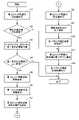
図5は、図4の機能的構成を有する図1の電子機器1が実行する輝度低減処理及び輝度制御処理の流れを説明するフローチャートである。 FIG. 5 is a flowchart illustrating a flow of a luminance reduction process and a luminance control process executed by the
輝度制御処理は、電子機器1の電源投入とともに開始され、電子機器1の電源をオフする操作が行われた場合に終了する。 The luminance control process starts when the power of the
ステップS1において、第2CPU11Bのセンサ情報取得部61は、照度センサ29から照度の検出値を取得する。 In step S1, the sensor
ステップS2において、第2CPU11Bのセンサ情報取得部61は、ステップS1で取得した照度の検出値が所定照度未満であるか否かを判定する。照度の検出値が所定照度未満であると判定された場合は、ステップS3に進む。他方、照度の検出値が所定照度未満でないと判定された場合は、ステップS11に進む。 In step S2, the sensor
ステップS3において、第2CPU11Bは、第1CPU11Aから、第1表示部18の現在の状態を表す情報(以下、「第1表示部情報」という)を取得する。第1表示部情報は、第1表示部18が点灯しているか否かを表す2値の情報であってもよいし、第1表示部18の点灯の際の輝度を表す情報であってもよい。 In step S3, the
ステップS4において、第2CPU11Bは、ステップS3で得た第1表示部情報に基づいて、第1表示部18が点灯しているか否かを判定する。すなわち、第2CPU11Bは、ステップS3で得た第1表示部情報に基づいて、第1表示部18の輝度が第1閾値以上か否かを判定する。この場合、第1閾値は、第1表示部18が点灯している場合の輝度の最小値に対応してよい。第1表示部18が点灯していると判定された場合は、ステップS5に進み、それ以外の場合は、終了する。 In step S4, the
ステップS5において、第2CPU11Bは、第1CPU11Aに対して輝度低減処理を要求する。 In step S5, the
ステップS6において、第1CPU11Aの輝度低減処理部52は、輝度低減処理を行う。輝度低減処理は、上述のとおりである。輝度低減処理が実行されると、上述のように、第2状態が形成される。 In step S6, the luminance
ステップS7において、第1CPU11Aは、輝度低減処理を行ったことを第2CPU11Bに通知する。 In step S7, the
ステップS8において、第2CPU11Bのセンサ情報取得部61は、照度センサ29から照度の検出値を取得する。このとき得られる照度の検出値は、第2状態において得られた検出値である。 In step S8, the sensor
ステップS9において、第2CPU11Bは、第1CPU11Aに対して輝度低減処理を終了するように要求する。 In step S9, the
ステップS10において、第1CPU11Aは、ステップS9の要求を受けて、第1表示部18を点灯させる(すなわち輝度低減処理を行う前の状態に戻す)。 In step S10, the
ステップS11において、第2CPU11Bのセンサ情報取得部61は、ステップS1で得た照度の検出値又はステップS8で得た照度の検出値を第1CPU11Aに通知する。具体的には、センサ情報取得部61は、ステップS2で判定結果が“NO”である場合は、ステップS1で得た照度の検出値を、第1CPU11Aに通知する。他方、センサ情報取得部61は、ステップS2で判定結果が“YES”である場合は、ステップS8で得た照度の検出値を、第1CPU11Aに通知する。この場合、第1CPU11Aの照度情報取得部51は、第2状態において得られた照度の検出値を取得する。 In step S11, the sensor
ステップS12において、第1CPU11Aの輝度制御部53は、ステップS11で得た照度の検出値(第2状態において得られた検出値)に基づいて、輝度制御処理を実行する。輝度制御処理は、上述のとおりである。電子機器1の電源をオフする操作が行われた場合、輝度制御処理は終了し、表示が継続する場合、処理はステップS1に戻り繰り返される。 In step S12, the
このような処理により、電子機器1においては、照度センサ29により検出された照度に応じて、第1表示部18の表示画面の輝度が調整される。そして、照度センサ29により検出された照度が予め設定された所定照度未満となった場合には、第1表示部18が点灯しているか否かの判定が行われる。そして、第1表示部18が点灯している場合には、照度センサ29の検出値に対する第1表示部18からの光の寄与が大きいと推定されることから、輝度低減処理によって第1表示部18の輝度が一時的に低下される。これにより、照度センサ29の検出値に対する第1表示部18からの光の寄与が低減され、信頼性の高い照度の検出値が得られる。この結果、信頼性の高い照度の検出値に基づいて輝度制御処理を実行でき、外光の照度に応じて行う制御(輝度制御処理)の信頼性を高めることができる。 By such processing, in the
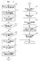
図6は、図5の変形例を示すフローチャートである。 FIG. 6 is a flowchart showing a modified example of FIG.
図6に示す処理は、図5に示した処理に対して、ステップS4がステップS4-1及びステップS4-2で置換された点が異なる。 The process shown in FIG. 6 is different from the process shown in FIG. 5 in that step S4 is replaced by step S4-1 and step S4-2.
ステップS4-1において、第2CPU11Bは、ステップS1で取得した照度の検出値に基づいて、第1閾値を設定する。このとき、第1閾値は、照度の検出値の所定割合(例えば90%)に設定されてよい。 In step S4-1, the
ステップS4-2において、第2CPU11Bは、ステップS3で得た第1表示部情報に基づいて、第1表示部18の輝度が、ステップS4-1で設定した第1閾値以上であるか否かを判定する。第1表示部18の輝度が第1閾値以上である場合は、ステップS5に進み、それ以外の場合は、終了する。 In step S4-2, the
このような処理により、電子機器1においては、照度センサ29により検出された照度に応じて、第1表示部18の表示画面の輝度が調整される。そして、照度センサ29により検出された照度が予め設定された所定照度未満となった場合には、第1表示部18の輝度が、検出された照度に応じた第1閾値以上であるか否かの判定が行われる。そして、第1表示部18の輝度が第1閾値以上である場合には、照度センサ29の検出値に対する第1表示部18からの光の寄与が大きいと推定されることから、輝度低減処理によって第1表示部18の輝度が一時的に低下される。これにより、照度センサ29の検出値に対する第1表示部18からの光の寄与が低減され、信頼性の高い照度の検出値が得られる。この結果、信頼性の高い照度の検出値に基づいて輝度制御処理を実行でき、外光の照度に応じて行う制御(輝度制御処理)の信頼性を高めることができる。 By such processing, in the
図7は、図5の他の変形例を示すフローチャートである。 FIG. 7 is a flowchart showing another modification of FIG.
図7に示す処理は、図5に示した処理に対して、ステップS3が無くされ、ステップS0-1及びステップS0-2が追加され、かつ、ステップS2及びステップS4がステップS2-1及びステップS4Aで置換された点が異なる。 In the process shown in FIG. 7, step S3 is eliminated, step S0-1 and step S0-2 are added to the process shown in FIG. 5, and steps S2 and S4 are steps S2-1 and step S2-1. The difference is that it is replaced by S4A.
ステップS0-1において、第2CPU11Bは、第1CPU11Aから、第1表示部18の現在の状態を表す情報(第1表示部情報)を取得する。図7では、第1表示部情報は、第1表示部18の点灯の際の輝度を表す情報である。 In step S0-1, the
ステップS0-2において、第2CPU11Bは、ステップS0-1で得た第1表示部情報に基づいて、第1表示部18の輝度に応じた所定照度を設定する。この際、第2CPU11Bは、第1表示部18の輝度が大きいほど所定照度が低くなる態様で、所定照度を設定する。すなわち、第2CPU11Bは、第1表示部18の輝度に基づいて、所定照度を可変する。 In step S0-2, the
ステップS2-1において、第2CPU11Bのセンサ情報取得部61は、ステップS1で取得した照度の検出値が、ステップS0-2で設定した所定照度よりも小さいか否かを判定する。照度の検出値が所定照度未満であると判定された場合は、ステップS4Aに進み、それ以外の場合は、ステップS11に進む。 In step S2-1, the sensor
ステップS4Aにおいて、第2CPU11Bは、ステップS0-1で得た第1表示部情報に基づいて、第1表示部18が点灯しているか否かを判定する。すなわち、第2CPU11Bは、ステップS0-1で得た第1表示部情報に基づいて、第1表示部18の輝度が第1閾値以上か否かを判定する。この場合、第1閾値は、第1表示部18が点灯している場合の輝度の最小値に対応してよい。第1表示部18が点灯していると判定された場合は、ステップS5に進み、それ以外の場合は、終了する。 In step S4A, the
なお、図7では、ステップS11において、第2CPU11Bのセンサ情報取得部61は、ステップS1で得た照度の検出値又はステップS8で得た照度の検出値を第1CPU11Aに通知する。具体的には、センサ情報取得部61は、ステップS2-1で判定結果が“NO”である場合は、ステップS1で得た照度の検出値を、第1CPU11Aに通知する。他方、センサ情報取得部61は、ステップS2-1で判定結果が“YES”である場合は、ステップS8で得た照度の検出値を、第1CPU11Aに通知する。この場合、第1CPU11Aの照度情報取得部51は、第2状態において得られた照度の検出値を取得する。 In FIG. 7, in step S11, the sensor
このような処理により、電子機器1においては、照度センサ29により検出された照度に応じて、第1表示部18の表示画面の輝度が調整される。そして、照度センサ29により検出された照度が、第1表示部18の輝度に応じた所定照度未満となった場合には、第1表示部18の輝度が、検出された照度に応じた第1閾値以上であるか否かの判定が行われる。そして、第1表示部18の輝度が第1閾値以上である場合には、照度センサ29の検出値に対する第1表示部18からの光の寄与が大きいと推定されることから、輝度低減処理によって第1表示部18の輝度が一時的に低下される。これにより、照度センサ29の検出値に対する第1表示部18からの光の寄与が低減され、信頼性の高い照度の検出値が得られる。この結果、信頼性の高い照度の検出値に基づいて輝度制御処理を実行でき、外光の照度に応じて行う制御(輝度制御処理)の信頼性を高めることができる。 By such processing, in the
なお、上述した一連の処理は、ハードウェアにより実行させることもできるし、ソフトウェアにより実行させることもできる。 The series of processes described above can be executed by hardware or software.
換言すると、上記のような機能的構成は例示に過ぎず、特に限定されない。すなわち、上述した一連の処理を全体として実行できる機能が電子機器1に備えられていれば足り、この機能を実現するためにどのような機能ブロックを用いるのかは、特に上記のような機能的構成に限定されない。また、1つの機能ブロックは、ハードウェア単体で構成してもよいし、ソフトウェア単体で構成してもよいし、それらの組み合わせで構成してもよい。 In other words, the above functional configuration is merely an example and is not particularly limited. That is, it suffices if the
本実施例における機能的構成は、演算処理を実行するプロセッサによって実現され、本実施例に用いることが可能なプロセッサには、シングルプロセッサ、マルチプロセッサ及びマルチコアプロセッサ等の各種処理装置単体によって構成されるものの他、これら各種処理装置と、ASIC(Application Specific Integrated Circuit)やFPGA(Field‐Programmable Gate Array)等の処理回路とが組み合わせられたものを含む。 The functional configuration in this embodiment is realized by a processor that executes arithmetic processing, and the processor that can be used in this embodiment is composed of various processing devices such as a single processor, a multiprocessor, and a multicore processor. In addition to the above, the present invention includes a combination of these various processing devices and a processing circuit such as an ASIC (Application Specific Integrated Circuit) or an FPGA (Field-Programmable Gate Array).
一連の処理をソフトウェアにより実行させる場合には、そのソフトウェアを構成するプログラムが、コンピュータ等にネットワークや記録媒体からインストールされる。
コンピュータは、専用のハードウェアに組み込まれているコンピュータであってもよい。また、コンピュータは、各種のプログラムをインストールすることで、各種の機能を実行することが可能なコンピュータ、例えば汎用のパーソナルコンピュータであってもよい。When a series of processes are executed by software, a program constituting the software is installed in a computer or the like from a network or a recording medium.
The computer may be a computer embedded in dedicated hardware. Further, the computer may be a computer capable of executing various functions by installing various programs, for example, a general-purpose personal computer.
このようなプログラムを含む記録媒体は、ユーザにプログラムを提供するために装置本体とは別に配布される図2のリムーバブルメディア41により構成されるだけでなく、装置本体に予め組み込まれた状態でユーザに提供される記録媒体等で構成される。リムーバブルメディア41は、例えば、磁気ディスク(フロッピディスクを含む)、光ディスク、または光磁気ディスク等により構成される。光ディスクは、例えば、CD-ROM(Compact Disk-Read Only Memory)、DVD(Digital Versatile Disk)、Blu-ray(登録商標) Disc(ブルーレイディスク)等により構成される。光磁気ディスクは、MD(Mini-Disk)等により構成される。また、装置本体に予め組み込まれた状態でユーザに提供される記録媒体は、例えば、プログラムが記録されている図2のROM12や、図2の記憶部14に含まれる半導体メモリ等で構成される。 The recording medium including such a program is not only composed of the
なお、本明細書において、記録媒体に記録されるプログラムを記述するステップは、その順序に沿って時系列的に行われる処理はもちろん、必ずしも時系列的に処理されなくても、並列的あるいは個別に実行される処理をも含むものである。 In the present specification, the steps for describing a program to be recorded on a recording medium are not only processed in chronological order but also in parallel or individually even if they are not necessarily processed in chronological order. It also includes the processing to be executed in.
以上、各実施例について詳述したが、特定の実施例に限定されるものではなく、特許請求の範囲に記載された範囲内において、種々の変形及び変更が可能である。また、前述した実施例の構成要素を全部又は複数を組み合わせることも可能である。 Although each embodiment has been described in detail above, the present invention is not limited to a specific embodiment, and various modifications and changes can be made within the scope of the claims. It is also possible to combine all or a plurality of the components of the above-described embodiment.
例えば、上述の実施例では、電子機器1は第1表示部18と第2表示部24とを備えるものとしたが、それに限らず、電子機器1は第1表示部18のみを備えるものであってもよい。 For example, in the above-described embodiment, the
また、上述の実施形態では、表示内容が表示される第1表示部18がOLEDで構成されるが、液晶ディスプレイ等の他の表示装置で構成されてもよい。 Further, in the above-described embodiment, the
また、上述の実施例では、電子機器1のCPU11は第1CPU11Aと第2CPU11Bとからなるものとしたが、それに限らず、CPU11は第1CPU11Aの機能と第2CPU11Bの機能の両方を備える1つのCPUであってもよい。 Further, in the above-described embodiment, the
また、上述の実施例では、本発明が適用される電子機器1は、デジタルカメラ腕時計型の装置(スマートウォッチ等)を例として説明したが、特にこれに限定されない。例えば、本発明は、輝度調整機能を有する電子機器一般に適用することができる。具体的には、例えば、本発明は、ノート型のパーソナルコンピュータ、プリンタ、テレビジョン受像機、ビデオカメラ、携帯型ナビゲーション装置、携帯電話機、スマートフォン、ポータブルゲーム機等に適用可能である。 Further, in the above-described embodiment, the
以下に、この出願の願書に最初に添付した特許請求の範囲に記載した発明を付記する。付記に記載した請求項の項番は、この出願の願書に最初に添付した特許請求の範囲の通りである。
<請求項1>
表示手段と、
前記表示手段の表示面の背面側に配置された照度検出手段と、
前記表示手段の発光レベルが第1閾値以上である第1状態で前記照度検出手段により検出された照度が所定照度未満の場合、前記表示手段の発光レベルを、前記第1閾値よりも小さい所定レベル以下に低減した第2状態で前記照度検出手段により照度を検出させる制御手段と、
を備えることを特徴とする電子機器。
<請求項2>
前記照度検出手段により検出された照度に基づいて、前記表示手段の輝度を調節する調節手段を備え、
前記調節手段は、前記第1状態で前記照度検出手段により検出された照度が前記所定照度未満の場合、前記第2状態で前記照度検出手段により検出された照度に基づいて、前記表示手段の輝度を調節することを特徴とする請求項1に記載の電子機器。
<請求項3>
前記制御手段は、前記第1状態で前記照度検出手段により検出された照度が前記所定照度以上の場合、前記表示手段の発光レベルを維持した状態で、照度を検出させることを特徴とする請求項1又は2に記載の電子機器。
<請求項4>
前記所定照度は、前記表示手段の発光レベルが大きいほど低くなる態様で、前記表示手段の発光レベルに応じて変化することを特徴とする請求項1から3のいずれか1項に記載の電子機器。
<請求項5>
前記表示手段の発光レベルは、前記表示手段の輝度、又は、前記表示手段が点灯しているか否かを示す情報であることを特徴とする請求項1から4のいずれか1項に記載の電子機器。
<請求項6>
表示手段の表示面の背面側に配置された照度検出手段により検出された照度が所定照度未満であり、かつ、前記表示手段の発光レベルが第1閾値以上である場合に、前記表示手段の発光レベルを、前記第1閾値よりも小さい所定レベル以下に低減し、
前記表示手段の発光レベルが前記所定レベル以下に低減した後、前記照度検出手段により照度を検出させることを含む、コンピュータにより実行される照度検出方法。
<請求項7>
表示手段の表示面の背面側に配置された照度検出手段により検出された照度が所定照度未満であり、かつ、前記表示手段の発光レベルが第1閾値以上である場合に、前記表示手段の発光レベルを、前記第1閾値よりも小さい所定レベル以下に低減し、
前記表示手段の発光レベルが前記所定レベル以下に低減した後、前記照度検出手段により照度を検出させる処理を、コンピュータに実行させる照度検出プログラム。The inventions described in the claims originally attached to the application of this application are described below. The claims described in the appendix are the scope of the claims originally attached to the application for this application.
<Claim 1>
Display means and
An illuminance detecting means arranged on the back side of the display surface of the display means,
When the illuminance detected by the illuminance detecting means is less than the predetermined illuminance in the first state where the light emitting level of the display means is equal to or higher than the first threshold value, the light emitting level of the display means is set to a predetermined level smaller than the first threshold value. The control means for detecting the illuminance by the illuminance detecting means in the second state reduced below,
An electronic device characterized by being equipped with.
<Claim 2>
An adjusting means for adjusting the brightness of the display means based on the illuminance detected by the illuminance detecting means is provided.
When the illuminance detected by the illuminance detecting means in the first state is less than the predetermined illuminance, the adjusting means has the brightness of the display means based on the illuminance detected by the illuminance detecting means in the second state. The electronic device according to
<Claim 3>
The control means is characterized in that when the illuminance detected by the illuminance detecting means in the first state is equal to or higher than the predetermined illuminance, the illuminance is detected while maintaining the light emission level of the display means. The electronic device according to 1 or 2.
<Claim 4>
The electronic device according to any one of
<Claim 5>
The electronic device according to any one of
<Claim 6>
When the illuminance detected by the illuminance detecting means arranged on the back side of the display surface of the display means is less than the predetermined illuminance and the light emission level of the display means is equal to or higher than the first threshold value, the light emission of the display means is emitted. The level is reduced to a predetermined level smaller than the first threshold value, and the level is reduced to a predetermined level or less.
An illuminance detection method performed by a computer, comprising detecting the illuminance by the illuminance detecting means after the light emitting level of the display means is reduced to the predetermined level or less.
<Claim 7>
When the illuminance detected by the illuminance detecting means arranged on the back side of the display surface of the display means is less than the predetermined illuminance and the light emission level of the display means is equal to or higher than the first threshold value, the light emission of the display means is emitted. The level is reduced to a predetermined level smaller than the first threshold value, and the level is reduced to a predetermined level or less.
An illuminance detection program that causes a computer to execute a process of detecting illuminance by the illuminance detecting means after the light emission level of the display means is reduced to the predetermined level or less.
1 電子機器
11A 第1CPU
11B 第2CPU
14 記憶部
15 RTC部
16 ドライブ
17 タッチパネル
18 第1表示部
19 第1入力部
20 ブルートゥース用アンテナ
21 ブルートゥースモジュール
22 無線LANアンテナ
23 無線LANモジュール
24 第2表示部
25 脈拍センサ
26 地磁気センサ
27 加速度センサ
28 ジャイロセンサ
29 照度センサ
30 第2入力部
31 GPSアンテナ
32 GPSモジュール
41 リムーバブルメディア
51 照度情報取得部
52 輝度低減処理部
53 輝度制御部
61 センサ情報取得部1
11B 2nd CPU
14
Claims (6)
Translated fromJapanese前記表示手段の表示面の背面側に配置され、表示手段からの光と表示手段を透過した外光とを検出する照度検出手段と、
前記表示手段の発光レベルが第1閾値以上である第1状態で前記照度検出手段により検出された照度が所定照度未満の場合、前記表示手段の発光レベルを、前記第1閾値よりも小さい所定レベル以下に低減した第2状態で前記照度検出手段により照度を検出させる制御手段と、
を備え、
前記所定照度は、前記表示手段の発光レベルが大きいほど低くなる態様で、前記表示手段の発光レベルに応じて変化する
ことを特徴とする電子機器。Display means and
An illuminance detecting means, which is arranged on the back side of the display surface ofthe display means and detects the light from the display means and the external light transmitted through the display means .
When the illuminance detected by the illuminance detecting means is less than the predetermined illuminance in the first state where the light emitting level of the display means is equal to or higher than the first threshold value, the light emitting level of the display means is set to a predetermined level smaller than the first threshold value. The control means for detecting the illuminance by the illuminance detecting means in the second state reduced below,
Equippedwith
The predetermined illuminance changes according to the light emission level of the display means in such a manner that the higher the light emission level of the display means is, the lower the illuminance is.
An electronic device characterized by that.
前記調節手段は、前記第1状態で前記照度検出手段により検出された照度が前記所定照度未満の場合、前記第2状態で前記照度検出手段により検出された照度に基づいて、前記表示手段の輝度を調節することを特徴とする請求項1に記載の電子機器。An adjusting means for adjusting the brightness of the display means based on the illuminance detected by the illuminance detecting means is provided.
When the illuminance detected by the illuminance detecting means in the first state is less than the predetermined illuminance, the adjusting means has the brightness of the display means based on the illuminance detected by the illuminance detecting means in the second state. The electronic device according to claim 1, wherein the device is adjusted.
前記表示手段の表示面の背面側に配置され、表示手段からの光と表示手段を透過した外光とを検出する照度検出手段と、
を備える電子機器が実行する照度検出方法であって、
前記表示手段の発光レベルが第1閾値以上である第1状態で前記照度検出手段により検出された照度が所定照度未満の場合、前記表示手段の発光レベルを、前記第1閾値よりも小さい所定レベル以下に低減した第2状態で前記照度検出手段により照度を検出させる制御処理、
を有し、
前記所定照度は、前記表示手段の発光レベルが大きいほど低くなる態様で、前記表示手段の発光レベルに応じて変化する
ことを特徴とする照度検出方法。Display meansand
An illuminance detecting means, which is arranged on the back side of the display surface of the display means and detects the light from the display means and the external light transmitted through the display means.
Is an illuminance detection method performed by an electronic device equipped with
When the illuminance detected by the illuminance detecting means is less than the predetermined illuminance in the first state where the light emitting level of the display means is equal to or higher than the first threshold value, the light emitting level of the display means is set to a predetermined level smaller than the first threshold value. A control process for detecting the illuminance by the illuminance detecting means in the second state reduced below.
Have,
The predetermined illuminance changes according to the light emission level of the display means in such a manner that the higher the light emission level of the display means is, the lower the illuminance is.
An illuminance detection method characterized by that .
前記表示手段の表示面の背面側に配置され、表示手段からの光と表示手段を透過した外光とを検出する照度検出手段と、
を備える電子機器のコンピュータを、
前記表示手段の発光レベルが第1閾値以上である第1状態で前記照度検出手段により検出された照度が所定照度未満の場合、前記表示手段の発光レベルを、前記第1閾値よりも小さい所定レベル以下に低減した第2状態で前記照度検出手段により照度を検出させる制御手段、
として機能させ、
前記所定照度は、前記表示手段の発光レベルが大きいほど低くなる態様で、前記表示手段の発光レベルに応じて変化する
ことを特徴とする照度検出プログラム。Display meansand
An illuminance detecting means, which is arranged on the back side of the display surface of the display means and detects the light from the display means and the external light transmitted through the display means.
Electronic device computer equipped with
When the illuminance detected by the illuminance detecting means is less than the predetermined illuminance in the first state where the light emitting level of the display means is equal to or higher than the first threshold value, the light emitting level of the display means is set to a predetermined level smaller than the first threshold value. A control means for detecting the illuminance by the illuminance detecting means in the second state reduced below.
To function as
The predetermined illuminance changes according to the light emission level of the display means in such a manner that the higher the light emission level of the display means is, the lower the illuminance is.
An illuminance detection program characterized by that .
Priority Applications (3)
| Application Number | Priority Date | Filing Date | Title |
|---|---|---|---|
| JP2018064733AJP7067195B2 (en) | 2018-03-29 | 2018-03-29 | Electronic devices, illuminance detection methods, and illuminance detection programs |
| US16/290,384US10891918B2 (en) | 2018-03-29 | 2019-03-01 | Electronic apparatus having function to reduce luminous intensity of display and detect intensity of ambient light in state in which luminous intensity of display is reduced, and light intensity detection method and storage medium storing light intensity detection program having same |
| CN201910245072.5ACN110322859B (en) | 2018-03-29 | 2019-03-28 | Electronic device, illumination detection method, and storage medium for storing illumination detection program |
Applications Claiming Priority (1)
| Application Number | Priority Date | Filing Date | Title |
|---|---|---|---|
| JP2018064733AJP7067195B2 (en) | 2018-03-29 | 2018-03-29 | Electronic devices, illuminance detection methods, and illuminance detection programs |
Publications (2)
| Publication Number | Publication Date |
|---|---|
| JP2019174718A JP2019174718A (en) | 2019-10-10 |
| JP7067195B2true JP7067195B2 (en) | 2022-05-16 |
Family
ID=68055457
Family Applications (1)
| Application Number | Title | Priority Date | Filing Date |
|---|---|---|---|
| JP2018064733AActiveJP7067195B2 (en) | 2018-03-29 | 2018-03-29 | Electronic devices, illuminance detection methods, and illuminance detection programs |
Country Status (3)
| Country | Link |
|---|---|
| US (1) | US10891918B2 (en) |
| JP (1) | JP7067195B2 (en) |
| CN (1) | CN110322859B (en) |
Citations (8)
| Publication number | Priority date | Publication date | Assignee | Title |
|---|---|---|---|---|
| JP2003337319A (en) | 2002-05-20 | 2003-11-28 | Fujitsu Ltd | Illumination light control device for display unit using optical sensor |
| JP2007121988A (en) | 2005-09-30 | 2007-05-17 | Seiko Epson Corp | Display method, display device, and electronic apparatus |
| JP2007232882A (en) | 2006-02-28 | 2007-09-13 | Casio Comput Co Ltd | Display device and electronic device |
| JP2008158497A (en) | 2006-11-27 | 2008-07-10 | Denso Corp | Vehicle display device |
| JP2009139784A (en) | 2007-12-10 | 2009-06-25 | Epson Imaging Devices Corp | Display device |
| US20170045918A1 (en) | 2015-08-13 | 2017-02-16 | Samsung Electronics Co., Ltd. | Electronic device including display and sensor |
| CN106462339A (en) | 2015-09-28 | 2017-02-22 | 华为技术有限公司 | Terminal and method for detecting ambient brightness |
| JP2017203948A (en) | 2016-05-13 | 2017-11-16 | キヤノン株式会社 | Display device and control method thereof |
Family Cites Families (16)
| Publication number | Priority date | Publication date | Assignee | Title |
|---|---|---|---|---|
| JP2005181562A (en)* | 2003-12-18 | 2005-07-07 | Pioneer Electronic Corp | Dimmer controller, its method, its program, recording medium recording the program, and display controller |
| US20070132749A1 (en) | 2005-12-12 | 2007-06-14 | Toppoly Optoelectronics Corp. | Systems for controlling brightness of displayed images |
| JP2007279093A (en)* | 2006-04-03 | 2007-10-25 | Epson Imaging Devices Corp | Liquid crystal display |
| US20130027371A1 (en)* | 2010-01-08 | 2013-01-31 | Sharp Kabushiki Kaisha | Electronic device, method for adjusting color saturation, program therefor, and recording medium |
| TWI497247B (en)* | 2010-01-28 | 2015-08-21 | Chi Mei Comm Systems Inc | Data processing device and method for realizing brightness adjustment |
| JP5270641B2 (en)* | 2010-11-10 | 2013-08-21 | シャープ株式会社 | Illuminance sensor and display device including the illuminance sensor |
| KR101824513B1 (en)* | 2010-12-29 | 2018-02-01 | 삼성전자 주식회사 | Terminal and brightness control method thereof |
| US9217867B2 (en)* | 2011-03-24 | 2015-12-22 | Seiko Epson Corporation | Head-mounted display device and control method for the head-mounted display device |
| US8749538B2 (en)* | 2011-10-21 | 2014-06-10 | Qualcomm Mems Technologies, Inc. | Device and method of controlling brightness of a display based on ambient lighting conditions |
| JP5592862B2 (en) | 2011-10-26 | 2014-09-17 | シャープ株式会社 | Liquid crystal display |
| JP2013125196A (en)* | 2011-12-15 | 2013-06-24 | Canon Inc | Display control apparatus and control method of display control apparatus |
| US8937632B2 (en)* | 2012-02-03 | 2015-01-20 | Ignis Innovation Inc. | Driving system for active-matrix displays |
| KR101526351B1 (en)* | 2012-07-20 | 2015-06-05 | 엘지전자 주식회사 | Mobile terminal and control method for mobile terminal |
| US8933866B2 (en)* | 2012-08-23 | 2015-01-13 | Blackberry Limited | Active matrix pixel brightness control |
| US9024530B2 (en)* | 2012-11-13 | 2015-05-05 | Apple Inc. | Synchronized ambient light sensor and display |
| CN108320721B (en)* | 2017-01-17 | 2022-05-24 | 华硕电脑股份有限公司 | Brightness adjusting device and brightness adjusting method thereof |
- 2018
- 2018-03-29JPJP2018064733Apatent/JP7067195B2/enactiveActive
- 2019
- 2019-03-01USUS16/290,384patent/US10891918B2/enactiveActive
- 2019-03-28CNCN201910245072.5Apatent/CN110322859B/enactiveActive
Patent Citations (8)
| Publication number | Priority date | Publication date | Assignee | Title |
|---|---|---|---|---|
| JP2003337319A (en) | 2002-05-20 | 2003-11-28 | Fujitsu Ltd | Illumination light control device for display unit using optical sensor |
| JP2007121988A (en) | 2005-09-30 | 2007-05-17 | Seiko Epson Corp | Display method, display device, and electronic apparatus |
| JP2007232882A (en) | 2006-02-28 | 2007-09-13 | Casio Comput Co Ltd | Display device and electronic device |
| JP2008158497A (en) | 2006-11-27 | 2008-07-10 | Denso Corp | Vehicle display device |
| JP2009139784A (en) | 2007-12-10 | 2009-06-25 | Epson Imaging Devices Corp | Display device |
| US20170045918A1 (en) | 2015-08-13 | 2017-02-16 | Samsung Electronics Co., Ltd. | Electronic device including display and sensor |
| CN106462339A (en) | 2015-09-28 | 2017-02-22 | 华为技术有限公司 | Terminal and method for detecting ambient brightness |
| JP2017203948A (en) | 2016-05-13 | 2017-11-16 | キヤノン株式会社 | Display device and control method thereof |
Also Published As
| Publication number | Publication date |
|---|---|
| CN110322859A (en) | 2019-10-11 |
| CN110322859B (en) | 2022-05-03 |
| US10891918B2 (en) | 2021-01-12 |
| US20190304399A1 (en) | 2019-10-03 |
| JP2019174718A (en) | 2019-10-10 |
Similar Documents
| Publication | Publication Date | Title |
|---|---|---|
| JP7468737B2 (en) | Electronic device, audio input sensitivity control method, and audio input sensitivity control program | |
| JP7613530B2 (en) | Display device, display method, and program | |
| JP7652316B2 (en) | Electronic device, control method, and program | |
| JP6733694B2 (en) | Electronic device, brightness control method and program | |
| US12181843B2 (en) | Electronic apparatus, information processing method, and storage medium storing information processing program | |
| JP2023024596A (en) | Display device, screen burn-in suppression method, and screen burn-in suppression program | |
| JP2020030392A (en) | Information processing apparatus, information processing method, and information processing program | |
| JP7067195B2 (en) | Electronic devices, illuminance detection methods, and illuminance detection programs | |
| JP7035692B2 (en) | Electronic devices, brightness control methods and programs | |
| JP7052460B2 (en) | Electronic devices, brightness control methods and programs | |
| JP2020003467A (en) | Electronic apparatus, information processing method, and information processing program | |
| US20200110371A1 (en) | Electronic device, information processing method, and non-transitory computer-readable recording medium | |
| JP7087531B2 (en) | Information processing equipment, information processing methods and information processing programs | |
| US20200302880A1 (en) | Electronic device | |
| WO2019124272A1 (en) | Electronic device, brightness control method, and recording medium |
Legal Events
| Date | Code | Title | Description |
|---|---|---|---|
| A621 | Written request for application examination | Free format text:JAPANESE INTERMEDIATE CODE: A621 Effective date:20210322 | |
| A977 | Report on retrieval | Free format text:JAPANESE INTERMEDIATE CODE: A971007 Effective date:20211222 | |
| A131 | Notification of reasons for refusal | Free format text:JAPANESE INTERMEDIATE CODE: A131 Effective date:20220106 | |
| A521 | Request for written amendment filed | Free format text:JAPANESE INTERMEDIATE CODE: A523 Effective date:20220302 | |
| TRDD | Decision of grant or rejection written | ||
| A01 | Written decision to grant a patent or to grant a registration (utility model) | Free format text:JAPANESE INTERMEDIATE CODE: A01 Effective date:20220329 | |
| A61 | First payment of annual fees (during grant procedure) | Free format text:JAPANESE INTERMEDIATE CODE: A61 Effective date:20220411 | |
| R150 | Certificate of patent or registration of utility model | Ref document number:7067195 Country of ref document:JP Free format text:JAPANESE INTERMEDIATE CODE: R150 |