JP7066529B2 - DC / DC conversion unit - Google Patents
DC / DC conversion unitDownload PDFInfo
- Publication number
- JP7066529B2 JP7066529B2JP2018104791AJP2018104791AJP7066529B2JP 7066529 B2JP7066529 B2JP 7066529B2JP 2018104791 AJP2018104791 AJP 2018104791AJP 2018104791 AJP2018104791 AJP 2018104791AJP 7066529 B2JP7066529 B2JP 7066529B2
- Authority
- JP
- Japan
- Prior art keywords
- converters
- battery
- control
- converter
- sub
- Prior art date
- Legal status (The legal status is an assumption and is not a legal conclusion. Google has not performed a legal analysis and makes no representation as to the accuracy of the status listed.)
- Active
Links
- 238000006243chemical reactionMethods0.000titleclaimsdescription35
- 230000005856abnormalityEffects0.000description9
- 238000001816coolingMethods0.000description8
- 230000004308accommodationEffects0.000description3
- 230000002159abnormal effectEffects0.000description2
- 238000010586diagramMethods0.000description2
- 238000000034methodMethods0.000description2
- 239000002826coolantSubstances0.000description1
- 230000007423decreaseEffects0.000description1
- 230000000694effectsEffects0.000description1
- 230000020169heat generationEffects0.000description1
- 239000007788liquidSubstances0.000description1
- 238000004088simulationMethods0.000description1
Images


Classifications
- B—PERFORMING OPERATIONS; TRANSPORTING
- B60—VEHICLES IN GENERAL
- B60L—PROPULSION OF ELECTRICALLY-PROPELLED VEHICLES; SUPPLYING ELECTRIC POWER FOR AUXILIARY EQUIPMENT OF ELECTRICALLY-PROPELLED VEHICLES; ELECTRODYNAMIC BRAKE SYSTEMS FOR VEHICLES IN GENERAL; MAGNETIC SUSPENSION OR LEVITATION FOR VEHICLES; MONITORING OPERATING VARIABLES OF ELECTRICALLY-PROPELLED VEHICLES; ELECTRIC SAFETY DEVICES FOR ELECTRICALLY-PROPELLED VEHICLES
- B60L50/00—Electric propulsion with power supplied within the vehicle
- B60L50/50—Electric propulsion with power supplied within the vehicle using propulsion power supplied by batteries or fuel cells
- B60L50/60—Electric propulsion with power supplied within the vehicle using propulsion power supplied by batteries or fuel cells using power supplied by batteries
- H—ELECTRICITY
- H02—GENERATION; CONVERSION OR DISTRIBUTION OF ELECTRIC POWER
- H02M—APPARATUS FOR CONVERSION BETWEEN AC AND AC, BETWEEN AC AND DC, OR BETWEEN DC AND DC, AND FOR USE WITH MAINS OR SIMILAR POWER SUPPLY SYSTEMS; CONVERSION OF DC OR AC INPUT POWER INTO SURGE OUTPUT POWER; CONTROL OR REGULATION THEREOF
- H02M3/00—Conversion of DC power input into DC power output
- H02M3/02—Conversion of DC power input into DC power output without intermediate conversion into AC
- H02M3/04—Conversion of DC power input into DC power output without intermediate conversion into AC by static converters
- H02M3/10—Conversion of DC power input into DC power output without intermediate conversion into AC by static converters using discharge tubes with control electrode or semiconductor devices with control electrode
- H02M3/145—Conversion of DC power input into DC power output without intermediate conversion into AC by static converters using discharge tubes with control electrode or semiconductor devices with control electrode using devices of a triode or transistor type requiring continuous application of a control signal
- H02M3/155—Conversion of DC power input into DC power output without intermediate conversion into AC by static converters using discharge tubes with control electrode or semiconductor devices with control electrode using devices of a triode or transistor type requiring continuous application of a control signal using semiconductor devices only
- B—PERFORMING OPERATIONS; TRANSPORTING
- B60—VEHICLES IN GENERAL
- B60L—PROPULSION OF ELECTRICALLY-PROPELLED VEHICLES; SUPPLYING ELECTRIC POWER FOR AUXILIARY EQUIPMENT OF ELECTRICALLY-PROPELLED VEHICLES; ELECTRODYNAMIC BRAKE SYSTEMS FOR VEHICLES IN GENERAL; MAGNETIC SUSPENSION OR LEVITATION FOR VEHICLES; MONITORING OPERATING VARIABLES OF ELECTRICALLY-PROPELLED VEHICLES; ELECTRIC SAFETY DEVICES FOR ELECTRICALLY-PROPELLED VEHICLES
- B60L1/00—Supplying electric power to auxiliary equipment of vehicles
- B—PERFORMING OPERATIONS; TRANSPORTING
- B60—VEHICLES IN GENERAL
- B60L—PROPULSION OF ELECTRICALLY-PROPELLED VEHICLES; SUPPLYING ELECTRIC POWER FOR AUXILIARY EQUIPMENT OF ELECTRICALLY-PROPELLED VEHICLES; ELECTRODYNAMIC BRAKE SYSTEMS FOR VEHICLES IN GENERAL; MAGNETIC SUSPENSION OR LEVITATION FOR VEHICLES; MONITORING OPERATING VARIABLES OF ELECTRICALLY-PROPELLED VEHICLES; ELECTRIC SAFETY DEVICES FOR ELECTRICALLY-PROPELLED VEHICLES
- B60L3/00—Electric devices on electrically-propelled vehicles for safety purposes; Monitoring operating variables, e.g. speed, deceleration or energy consumption
- B60L3/0092—Electric devices on electrically-propelled vehicles for safety purposes; Monitoring operating variables, e.g. speed, deceleration or energy consumption with use of redundant elements for safety purposes
- B—PERFORMING OPERATIONS; TRANSPORTING
- B60—VEHICLES IN GENERAL
- B60L—PROPULSION OF ELECTRICALLY-PROPELLED VEHICLES; SUPPLYING ELECTRIC POWER FOR AUXILIARY EQUIPMENT OF ELECTRICALLY-PROPELLED VEHICLES; ELECTRODYNAMIC BRAKE SYSTEMS FOR VEHICLES IN GENERAL; MAGNETIC SUSPENSION OR LEVITATION FOR VEHICLES; MONITORING OPERATING VARIABLES OF ELECTRICALLY-PROPELLED VEHICLES; ELECTRIC SAFETY DEVICES FOR ELECTRICALLY-PROPELLED VEHICLES
- B60L50/00—Electric propulsion with power supplied within the vehicle
- B60L50/50—Electric propulsion with power supplied within the vehicle using propulsion power supplied by batteries or fuel cells
- B60L50/51—Electric propulsion with power supplied within the vehicle using propulsion power supplied by batteries or fuel cells characterised by AC-motors
- B—PERFORMING OPERATIONS; TRANSPORTING
- B60—VEHICLES IN GENERAL
- B60L—PROPULSION OF ELECTRICALLY-PROPELLED VEHICLES; SUPPLYING ELECTRIC POWER FOR AUXILIARY EQUIPMENT OF ELECTRICALLY-PROPELLED VEHICLES; ELECTRODYNAMIC BRAKE SYSTEMS FOR VEHICLES IN GENERAL; MAGNETIC SUSPENSION OR LEVITATION FOR VEHICLES; MONITORING OPERATING VARIABLES OF ELECTRICALLY-PROPELLED VEHICLES; ELECTRIC SAFETY DEVICES FOR ELECTRICALLY-PROPELLED VEHICLES
- B60L53/00—Methods of charging batteries, specially adapted for electric vehicles; Charging stations or on-board charging equipment therefor; Exchange of energy storage elements in electric vehicles
- B60L53/20—Methods of charging batteries, specially adapted for electric vehicles; Charging stations or on-board charging equipment therefor; Exchange of energy storage elements in electric vehicles characterised by converters located in the vehicle
- H—ELECTRICITY
- H02—GENERATION; CONVERSION OR DISTRIBUTION OF ELECTRIC POWER
- H02J—CIRCUIT ARRANGEMENTS OR SYSTEMS FOR SUPPLYING OR DISTRIBUTING ELECTRIC POWER; SYSTEMS FOR STORING ELECTRIC ENERGY
- H02J1/00—Circuit arrangements for DC mains or DC distribution networks
- H02J1/10—Parallel operation of DC sources
- H02J1/102—Parallel operation of DC sources being switching converters
- H—ELECTRICITY
- H02—GENERATION; CONVERSION OR DISTRIBUTION OF ELECTRIC POWER
- H02M—APPARATUS FOR CONVERSION BETWEEN AC AND AC, BETWEEN AC AND DC, OR BETWEEN DC AND DC, AND FOR USE WITH MAINS OR SIMILAR POWER SUPPLY SYSTEMS; CONVERSION OF DC OR AC INPUT POWER INTO SURGE OUTPUT POWER; CONTROL OR REGULATION THEREOF
- H02M1/00—Details of apparatus for conversion
- H02M1/32—Means for protecting converters other than automatic disconnection
- B—PERFORMING OPERATIONS; TRANSPORTING
- B60—VEHICLES IN GENERAL
- B60L—PROPULSION OF ELECTRICALLY-PROPELLED VEHICLES; SUPPLYING ELECTRIC POWER FOR AUXILIARY EQUIPMENT OF ELECTRICALLY-PROPELLED VEHICLES; ELECTRODYNAMIC BRAKE SYSTEMS FOR VEHICLES IN GENERAL; MAGNETIC SUSPENSION OR LEVITATION FOR VEHICLES; MONITORING OPERATING VARIABLES OF ELECTRICALLY-PROPELLED VEHICLES; ELECTRIC SAFETY DEVICES FOR ELECTRICALLY-PROPELLED VEHICLES
- B60L2210/00—Converter types
- B60L2210/10—DC to DC converters
- H—ELECTRICITY
- H02—GENERATION; CONVERSION OR DISTRIBUTION OF ELECTRIC POWER
- H02M—APPARATUS FOR CONVERSION BETWEEN AC AND AC, BETWEEN AC AND DC, OR BETWEEN DC AND DC, AND FOR USE WITH MAINS OR SIMILAR POWER SUPPLY SYSTEMS; CONVERSION OF DC OR AC INPUT POWER INTO SURGE OUTPUT POWER; CONTROL OR REGULATION THEREOF
- H02M1/00—Details of apparatus for conversion
- H02M1/0067—Converter structures employing plural converter units, other than for parallel operation of the units on a single load
- H—ELECTRICITY
- H02—GENERATION; CONVERSION OR DISTRIBUTION OF ELECTRIC POWER
- H02M—APPARATUS FOR CONVERSION BETWEEN AC AND AC, BETWEEN AC AND DC, OR BETWEEN DC AND DC, AND FOR USE WITH MAINS OR SIMILAR POWER SUPPLY SYSTEMS; CONVERSION OF DC OR AC INPUT POWER INTO SURGE OUTPUT POWER; CONTROL OR REGULATION THEREOF
- H02M3/00—Conversion of DC power input into DC power output
- H02M3/02—Conversion of DC power input into DC power output without intermediate conversion into AC
- H02M3/04—Conversion of DC power input into DC power output without intermediate conversion into AC by static converters
- H02M3/10—Conversion of DC power input into DC power output without intermediate conversion into AC by static converters using discharge tubes with control electrode or semiconductor devices with control electrode
- H02M3/145—Conversion of DC power input into DC power output without intermediate conversion into AC by static converters using discharge tubes with control electrode or semiconductor devices with control electrode using devices of a triode or transistor type requiring continuous application of a control signal
- H02M3/155—Conversion of DC power input into DC power output without intermediate conversion into AC by static converters using discharge tubes with control electrode or semiconductor devices with control electrode using devices of a triode or transistor type requiring continuous application of a control signal using semiconductor devices only
- H02M3/156—Conversion of DC power input into DC power output without intermediate conversion into AC by static converters using discharge tubes with control electrode or semiconductor devices with control electrode using devices of a triode or transistor type requiring continuous application of a control signal using semiconductor devices only with automatic control of output voltage or current, e.g. switching regulators
- H02M3/158—Conversion of DC power input into DC power output without intermediate conversion into AC by static converters using discharge tubes with control electrode or semiconductor devices with control electrode using devices of a triode or transistor type requiring continuous application of a control signal using semiconductor devices only with automatic control of output voltage or current, e.g. switching regulators including plural semiconductor devices as final control devices for a single load
- H02M3/1584—Conversion of DC power input into DC power output without intermediate conversion into AC by static converters using discharge tubes with control electrode or semiconductor devices with control electrode using devices of a triode or transistor type requiring continuous application of a control signal using semiconductor devices only with automatic control of output voltage or current, e.g. switching regulators including plural semiconductor devices as final control devices for a single load with a plurality of power processing stages connected in parallel
- Y—GENERAL TAGGING OF NEW TECHNOLOGICAL DEVELOPMENTS; GENERAL TAGGING OF CROSS-SECTIONAL TECHNOLOGIES SPANNING OVER SEVERAL SECTIONS OF THE IPC; TECHNICAL SUBJECTS COVERED BY FORMER USPC CROSS-REFERENCE ART COLLECTIONS [XRACs] AND DIGESTS
- Y02—TECHNOLOGIES OR APPLICATIONS FOR MITIGATION OR ADAPTATION AGAINST CLIMATE CHANGE
- Y02T—CLIMATE CHANGE MITIGATION TECHNOLOGIES RELATED TO TRANSPORTATION
- Y02T10/00—Road transport of goods or passengers
- Y02T10/60—Other road transportation technologies with climate change mitigation effect
- Y02T10/70—Energy storage systems for electromobility, e.g. batteries
- Y—GENERAL TAGGING OF NEW TECHNOLOGICAL DEVELOPMENTS; GENERAL TAGGING OF CROSS-SECTIONAL TECHNOLOGIES SPANNING OVER SEVERAL SECTIONS OF THE IPC; TECHNICAL SUBJECTS COVERED BY FORMER USPC CROSS-REFERENCE ART COLLECTIONS [XRACs] AND DIGESTS
- Y02—TECHNOLOGIES OR APPLICATIONS FOR MITIGATION OR ADAPTATION AGAINST CLIMATE CHANGE
- Y02T—CLIMATE CHANGE MITIGATION TECHNOLOGIES RELATED TO TRANSPORTATION
- Y02T10/00—Road transport of goods or passengers
- Y02T10/60—Other road transportation technologies with climate change mitigation effect
- Y02T10/7072—Electromobility specific charging systems or methods for batteries, ultracapacitors, supercapacitors or double-layer capacitors
- Y—GENERAL TAGGING OF NEW TECHNOLOGICAL DEVELOPMENTS; GENERAL TAGGING OF CROSS-SECTIONAL TECHNOLOGIES SPANNING OVER SEVERAL SECTIONS OF THE IPC; TECHNICAL SUBJECTS COVERED BY FORMER USPC CROSS-REFERENCE ART COLLECTIONS [XRACs] AND DIGESTS
- Y02—TECHNOLOGIES OR APPLICATIONS FOR MITIGATION OR ADAPTATION AGAINST CLIMATE CHANGE
- Y02T—CLIMATE CHANGE MITIGATION TECHNOLOGIES RELATED TO TRANSPORTATION
- Y02T10/00—Road transport of goods or passengers
- Y02T10/60—Other road transportation technologies with climate change mitigation effect
- Y02T10/72—Electric energy management in electromobility
- Y—GENERAL TAGGING OF NEW TECHNOLOGICAL DEVELOPMENTS; GENERAL TAGGING OF CROSS-SECTIONAL TECHNOLOGIES SPANNING OVER SEVERAL SECTIONS OF THE IPC; TECHNICAL SUBJECTS COVERED BY FORMER USPC CROSS-REFERENCE ART COLLECTIONS [XRACs] AND DIGESTS
- Y02—TECHNOLOGIES OR APPLICATIONS FOR MITIGATION OR ADAPTATION AGAINST CLIMATE CHANGE
- Y02T—CLIMATE CHANGE MITIGATION TECHNOLOGIES RELATED TO TRANSPORTATION
- Y02T90/00—Enabling technologies or technologies with a potential or indirect contribution to GHG emissions mitigation
- Y02T90/10—Technologies relating to charging of electric vehicles
- Y02T90/14—Plug-in electric vehicles
Landscapes
- Engineering & Computer Science (AREA)
- Power Engineering (AREA)
- Transportation (AREA)
- Mechanical Engineering (AREA)
- Life Sciences & Earth Sciences (AREA)
- Sustainable Development (AREA)
- Sustainable Energy (AREA)
- Charge And Discharge Circuits For Batteries Or The Like (AREA)
- Electric Propulsion And Braking For Vehicles (AREA)
- Dc-Dc Converters (AREA)
- Direct Current Feeding And Distribution (AREA)
Description
Translated fromJapanese本発明は、DC/DC変換ユニットに関する。 The present invention relates to a DC / DC conversion unit.
近年、ハイブリッド車や電気自動車においては、駆動モータ用の高圧バッテリ(駆動電源)と、該高圧バッテリからの出力を駆動モータ以外の各種電装品に対応する電圧に変換するDC/D変換器と、を備えるものが提案されている。 In recent years, in hybrid vehicles and electric vehicles, high-pressure batteries (drive power supplies) for drive motors and DC / D converters that convert the output from the high-pressure batteries into voltages corresponding to various electrical components other than drive motors. Those equipped with are proposed.
また、車両の運転中に、DC/DC変換器の故障などにより上記電装品に対する電源供給が失われないようにするため、DC/DC変換器を2つ設ける技術が提案されている(特許文献1)。特に、電装品が自動運転に関係するものである場合に有効な技術である。 Further, in order to prevent the power supply to the electrical components from being lost due to a failure of the DC / DC converter while the vehicle is in operation, a technique of providing two DC / DC converters has been proposed (Patent Document). 1). In particular, it is an effective technique when electrical components are related to automatic operation.
しかしながら、DC/DC変換器は発熱量が多いため、DC/DC変換器を2つ設けると冷却系も2つ必要となり、コスト的に問題があった。 However, since the DC / DC converter has a large amount of heat generation, if two DC / DC converters are provided, two cooling systems are required, which is costly.
本発明は、以上の背景に鑑みてなされたものであり、コストダウンを図ったDC/DC変換ユニットを提供することを目的としている。 The present invention has been made in view of the above background, and an object of the present invention is to provide a DC / DC conversion unit with reduced cost.
本発明の態様であるDC/DC変換ユニットは、車両のモータに電源供給する駆動電源の電源電圧をDC/DC変換して、車両に搭載された電装品に供給する2つのDC/DC変換器と、前記2つのDC/DC変換器を収容する収容ケースと、を備えたことを特徴とする。 The DC / DC conversion unit according to the embodiment of the present invention is two DC / DC converters that DC / DC convert the power supply voltage of the drive power supply that supplies power to the motor of the vehicle and supply it to the electrical components mounted on the vehicle. And a storage case for accommodating the two DC / DC converters.
また、前記2つのDC/DC変換器をそれぞれ独立して制御する2つの制御部をさらに備えてもよい。 Further, two control units that independently control the two DC / DC converters may be further provided.
また、前記2つのDC/DC変換器の出力間に接続されたスイッチをさらに備え、前記2つの制御部は、互いを監視し、前記2つの制御部のうち何れか一方の故障を検出すると前記スイッチをオフ制御してもよい。 Further, a switch connected between the outputs of the two DC / DC converters is further provided, and the two control units monitor each other and detect a failure of either one of the two control units. The switch may be controlled off.
また、前記スイッチは、前記収容ケースに収容されていてもよい。 Further, the switch may be housed in the housing case.
また、前記電装品と2つのDC/DC変換器の出力との間にそれぞれ2つの電装品電源が設けられていてもよい。 Further, two electrical component power supplies may be provided between the electrical component and the outputs of the two DC / DC converters.
以上説明したように上記態様によれば、1つの収容ケースに、2つのDC/DC変換器を収容することにより、2つのDC/DC変換器に対して共通の冷却系を用いることができ、コストダウンを図ることができる。 As described above, according to the above aspect, by accommodating two DC / DC converters in one accommodating case, a common cooling system for the two DC / DC converters can be used. It is possible to reduce costs.
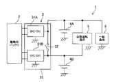
以下、本発明の一実施形態を、図1及び図2に基づいて説明する。図1に示す電源装置1は、モータ(図示せず)により駆動するハイブリッド車、電気自動車などに搭載され、電装品である自動運転負荷5や一般負荷6に電源を供給する。 Hereinafter, an embodiment of the present invention will be described with reference to FIGS. 1 and 2. The
同図に示すように、電源装置1は、駆動電源としての駆動用バッテリ2と、DC/DC変換ユニット3と、電装品電源としての2つの第1サブバッテリ4A、第2サブバッテリ4Bと、自動運転負荷5と、一般負荷6と、を備えている。 As shown in the figure, the
駆動用バッテリ2は、ハイブリッド車や電気自動車の駆動用の動力源であるモータを駆動させることを主目的とするメインバッテリである。駆動用バッテリ2は、直流を交流に変換するインバータ回路(図示せず)を介してモータに接続されている。このため、駆動用バッテリ2としては、高電圧、大容量のバッテリを用いている。 The
DC/DC変換ユニット3は、高圧の駆動用バッテリ2の電源電圧をDC/DC変換して、低圧の第1サブバッテリ4A、第2サブバッテリ4Bや自動運転負荷5、一般負荷6に供給する。DC/DC変換ユニット3の詳細については後述する。 The DC / DC conversion unit 3 converts the power supply voltage of the high-
第1、第2サブバッテリ4A、4Bは、モータ以外の低圧で駆動する電装品(自動運転負荷5、一般負荷)を駆動させることを主目的とするサブバッテリである。このため、第1、第2サブバッテリ4A、4Bとしては、駆動用バッテリ2に比べて低電圧、小容量のバッテリを用いている。 The first and
また、第1、第2サブバッテリ4A、4Bは各々別体に設けられている。第1サブバッテリ4Aは、DC/DC変換ユニット3から出力される電力により充電されると共に、自動運転負荷5及び一般負荷6の双方に電力を供給する。第2サブバッテリ4Bは、DC/DC変換ユニット3から出力される電力により充電されると共に、自動運転負荷5のみに電力を供給する。第2サブバッテリ4Bから一般負荷6へは電力が供給されない。 Further, the first and
第1、第2サブバッテリ4A、4Bは、出力電圧が同じバッテリである。第2サブバッテリ4Bは、DC/DC変換ユニット3から第1バッテリ4Aへの充電が途絶える電源異常が生じたときに、少なくとも自動運転負荷5に電力供給を継続させるための補助的なバッテリである。これにより、車両は、上述した電源異常が生じても、自動運転を継続させることができ、最寄のサービス拠点に戻ることができる。 The first and
本実施形態では、第2サブバッテリ4Bは自動運転負荷5のみに電力を供給し、第1サブバッテリ4Aよりも容量を少ないものを採用している。勿論これに限ったものではなく、第2サブバッテリ4Bは自動運転負荷5及び一般負荷6の双方に電力を供給できるようにしてもよいし、第1サブバッテリ4Aと第2サブバッテリ4Bとの容量を同じにしてもよい。 In the present embodiment, the
自動運転負荷5は、アクセル、ハンドル、ブレーキの少なくとも一つの駆動、制御などを行う、自動運転に必要な電装品から構成されている。一般負荷6は、エアコンやオーディオなど自動運転に必要ではない電装品から構成されている。 The
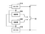
次に、DC/DC変換ユニット3の詳細について説明する。DC/DC変換ユニット3は、2つのDC/DC変換器31A、31Bと、スイッチ32と、これら2つのDC/DC変換器31A、31B及びスイッチ32を収容する収容ケース33と、2つの制御部34A、34B(図2)と、を備えている。 Next, the details of the DC / DC conversion unit 3 will be described. The DC / DC conversion unit 3 includes two DC /
2つのDC/DC変換器31A、31Bは各々、スイッチング素子、コイルなどから構成された周知のDC/DC変換器である。2つのDC/DC変換器31A、31Bは各々、駆動用バッテリ2の電源電圧を降圧して第1、第2サブバッテリ4A、4B、自動運転負荷5、一般負荷6に適した電圧に変換する。 The two DC /
DC/DC変換器31Aの出力には、第1サブバッテリ4Aが接続される。DC/DC変換器31Bの出力には、第2サブバッテリ4Bが接続される。 A
スイッチ32は、2つのDC/DC変換器31A、31Bの出力間に設けられている。このスイッチ32をオンすると、2つのDC/DC変換器31A、31Bの出力間が接続され、DC/DC変換器31Aの出力に第2サブバッテリ4Bが接続されると共に、DC/DC変換器31Bの出力に第1サブバッテリ4Aが接続される。上記スイッチ32をオフすると、2つのDC/DC変換器31A、31Bの出力間が切断され、DC/DC変換器31Aの出力と第2サブバッテリ4Bとの接続が切り離されると共に、DC/DC変換器31Bの出力と第1サブバッテリ4Aとの接続が切り離される。 The
上記スイッチ32は、後述する2つの制御部34A、34B(図2)の双方によりオンオフ制御される。制御部34A、34Bは、通常時はスイッチ32をオンする。これにより、通常時において、第1サブバッテリ4Aは、2つのDC/DC変換器31A、31Bの双方の出力電力により充電され、第2サブバッテリ4Bも、2つのDC/DC変換器31A、31Bの双方の出力電力により充電される。 The
一方、制御部34A、34Bは、2つのDC/DC変換器31A、31Bの何れか一方に異常が発生した時はスイッチ32をオフする。例えば、DC/DC変換器31Aの異常発生時にスイッチ32がオフすると、異常が発生したDC/DC変換器31Aと第2サブバッテリ4Bとの接続が切り離される。これにより、異常なDC/DC変換器31Aの出力電圧が、第2サブバッテリ4Bや自動運転負荷5に供給されることがなく、正常なDC/DC変換器31Bの出力電圧のみが第2サブバッテリ4Bや自動運転負荷5に供給されるため、自動運転負荷5への電源供給を継続できる。 On the other hand, the
同様に、DC/DC変換器31Bの異常発生時にスイッチ32がオフすると、異常が発生したDC/DC変換器31Bと第1サブバッテリ4Aとの接続が切り離される。これにより、異常なDC/DC変換器31Bの出力電圧が、第1サブバッテリ4Aや自動運転負荷5、一般負荷6に供給されることがなく、正常なDC/DC変換器31Aの出力電圧のみが第1サブバッテリ4Aや自動運転負荷5、一般負荷6に供給されるため、自動運転負荷5、一般負荷6への電源供給を継続できる。 Similarly, when the
上記2つのDC/DC変換器31A、31Bは、1つの収容ケース33内に収容されている。即ち、1つの収容ケース33によって外部空間とは仕切られた1つの空間に、2つのDC/DC変換器31A、31Bが収容される。このように1つの収容ケース33に、2つのDC/DC変換器31A、31Bが収容されているので、2つのDC/DC変換器31A、31Bに対して共通の冷却系を用いることができ、コストダウンを図ることができる。 The two DC /
冷却系としては、収容ケース33内の温度を冷却できる周知の冷却系を用いればよい。冷却系としては、例えば、外部の空気を収容ケース33内に取り込む冷却ファンを設ける構成や、収容ケース33内に熱交換器などを設ける構成することが考えられる。また、冷却媒体としては、液体であってもよいし、気体であってもよい。 As the cooling system, a well-known cooling system capable of cooling the temperature inside the
また、スイッチ32も、1つの収容ケース33内に収容されている。このため、スイッチ32をDC/DC変換器31A、31Bの近くに配置することにより、DC/DC変換器31A、31Bを制御する後述する制御部34A、34Bによりスイッチ32のオンオフを制御できる。即ち、制御部34A、34Bとは別にスイッチ32のオンオフ制御用の制御部を設ける必要がなく、コストダウンを図ることができる。 The
2つの制御部34A、34Bは、例えば、CPU、ROM、RAMなどから構成されたマイクロコンピュータから構成され、2つのDC/DC変換器31A、31Bをそれぞれ独立して制御する。「独立して制御する」とは、2つの制御部34A、34Bは各々別々の部品から構成されていることを意味し、制御部34Aを構成するマイコンと、制御部34Bを構成するマイコンと、は別部品であることを意味する。 The two
このように制御部34A、34Bを2つ設け、それぞれにDC/DC変換器31A、31Bの制御を独立して行わせることにより、制御部34A、34Bの一方が故障しても他方が対応するDC/DC変換器31A、31Bの動作を継続させることができる。このため、自動運転負荷5への電源供給遮断を抑制することができる。 By providing two
そして、制御部34Aが、DC/DC変換器31Aの変換制御を行い、制御部34Bが、DC/DC変換器31Bの変換制御を行い、DC/DC変換器31A、31Bから所望の出力電圧が出力されるように制御する。2つの制御部34A、34Bは、収容ケース33内に収容されていてもよいし、収容ケース33の外部に設けてもよい。 Then, the
次に、上記2つの制御部34A、34Bが行う変換制御について説明する。2つの制御部34A、34Bは各々、2つのDC/DC変換器31A、31Bに内蔵されたスイッチング素子のオンオフ制御を行うことによって、DC/DC変換器31A、31Bの動作を制御している。 Next, the conversion control performed by the above two
本実施形態では、2つの制御部34A、34Bは、例えばイグニッションスイッチのオンに応じてDC/DC変換器31A、31Bの制御を開始するが、同時に変換制御を開始せず、以下に示す協調制御を実行する。協調制御において、まず、先に制御部34Bが、DC/DC変換器31Bの変換制御を開始する。このとき、DC/DC変換器31Aの動作は停止されている。その後、DC/DC変換器31Bの出力電力がある程度高くなると、もう一方の制御部34AがDC/DC変換器31Aの変換制御を開始する。 In the present embodiment, the two
これにより、変換開始時の出力電力が低いときに2つのDC/DC変換器31A、31Bの動作が実行されることがなく、効率向上を図ることができる。なお、DC/DC変換器31Aの変換制御開始のタイミングは、DC/DC変換器31Bの出力電圧が閾値を上回ったタイミングでもよいし、DC/DC変換器31Bの制御開始から予め定めた時間経過したタイミングとしてもよい。 As a result, when the output power at the start of conversion is low, the operations of the two DC /
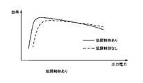
上記効果をシミュレーションにより確認する。図3は、DC/DC変換器31A、31B各々の出力電力に対する効率の関係を示すグラフである。2つのDC/DC変換器31A、31Bは、同じ出力電力対効率特性のものを用いている。同図に示すように、DC/DC変換器31A、31Bは、出力電力が低い間、効率が悪く、出力電力が高くなるに従って急激に効率がよくなる。そして、出力電力がある程度高くなると、出力電力が高くなるに従って緩やかに効率が低下する。 Confirm the above effect by simulation. FIG. 3 is a graph showing the relationship of efficiency with respect to the output power of each of the DC /
そして、制御部34A、34Bが上記特性のDC/DC変換器31A、31Bの協調制御を実行した時と、制御部34A、34Bが協調制御を実行しなかった時(即ち2つのDC/DC変換器31A、31Bの変換制御を同時に開始する制御を実行した時)の出力電力に対する効率の関係をシミュレーションした。結果を図4に示す。同図からも明らかなように、協調制御を行うことにより、出力電力が低いときの効率を改善することができることが分かった。 Then, when the
なお、上記実施形態によれば、2つのDC/DC変換器31A、31Bの出力電力対効率特性は同じであったが、これに限ったものではない。例えば、図5及び図7に示すように2つのDC/DC変換器31A、31Bの出力電力対効率特性が異なっていてもよい。なお、図6は、図5に示す特性を有するDC/DC変換器31A、31Bを協調制御したとき、協調制御しなかったとき、それぞれの出力電力に対する効率の関係を示すグラフである。また、図8は、図7に示す特性を有するDC/DC変換器31A、31Bを協調制御したとき、協調制御しなかったとき、それぞれの出力電力に対する効率の関係を示すグラフである。図5及び図7に示すように、DC/DC変換器31Bは、DC/DC変換器31Aに比べて出力電力が低いときの効率がよいが、出力電力が高いときの効率は悪い。 According to the above embodiment, the output power vs. efficiency characteristics of the two DC /
この場合、制御部34A、34Bが、出力電力が低いときの効率がよいDC/DC変換器31Bの変換制御を先に開始して、後から出力電力が高いときの効率がよいDC/DC変換器31Aの変換制御を開始すれば、図6及び図8に示すように、出力電力が低いときの効率をより一層、改善することができる。 In this case, the
また、2つの制御部34A、34Bは、互いに監視して、2つの制御部34A、34Bのうち何れか一方の故障を検出すると、DC/DC変換器31A、31Bの何れか一方に異常が生じていると判断してスイッチ32をオフ制御する。制御部34Aは、自身からDC/DC変換器31Aに対して出力される制御信号、制御部34BからDC/DC変換器31Bに対して出力される制御信号を監視して、何れか一方でも制御信号が出力されなくなると、スイッチ32をオフする。 Further, when the two
同様に、制御部34Bも、自身からDC/DC変換器31Bに対して出力される制御信号、制御部34AからDC/DC変換器31Aに対して出力される制御信号を監視して、何れか一方でも制御信号が出力されなくなると、スイッチ32をオフする。 Similarly, the
制御部34Aが故障するとDC/DC変換器31Aからの所望の出力電圧が出力されなくなる。本実施形態では、制御部34Aが故障すると、制御部34A、34Bがスイッチ32をオフして異常が発生しているDC/DC変換器31Aを切り離すことができる。そして、正常なDC/DC変換器31Bからの出力電圧により第2サブバッテリ4B、自動運転負荷5への電源供給を継続させることができる。 If the
また、制御部34Bが故障した場合は、制御部34A、34Bがスイッチ32をオフして異常が発生しているDC/DC変換器31Bを切り離すことができる。そして、正常なDC/DC変換器31Aからの出力に基づいて第1サブバッテリ4A、自動運転負荷5及び一般負荷6への電源供給を継続させることができる。 Further, when the
なお、上述した実施形態によれば、DC/DC変換器31A、31Bは2つの制御部34A、34Bによってそれぞれ独立して制御されていたが、これに限ったものではない。1つの制御部によって2つのDC/DC変換器31A、31Bを制御するようにしてもよい。 According to the above-described embodiment, the DC /
また、上述した実施形態によれば、スイッチ32は、収容ケース33に収容されていたが、これに限ったものではない。スイッチ32を収容ケース33外に設けてもよい。 Further, according to the above-described embodiment, the
また、上述した実施形態によれば、電源装置1には2つの第1サブバッテリ4A、第2サブバッテリ4Bが設けられていたが、これに限ったものではない。第1サブバッテリ4Aのみ設けるようにしてもよい。 Further, according to the above-described embodiment, the
また、上述した実施形態によれば、制御部34A、34Bは、DC/DC変換器31Bの変換制御を先に開始し、その後、DC/DC変換器31Aの変換制御を開始していたが、これに限ったものではない。DC/DC変換器31Aの変換制御を先に開始し、その後、DC/DC変換器31Bの変換制御を開始するようにしてもよい。 Further, according to the above-described embodiment, the
なお、本発明は上記実施形態に限定されるものではない。即ち、本発明の骨子を逸脱しない範囲で種々変形して実施することができる。 The present invention is not limited to the above embodiment. That is, it can be variously modified and carried out within a range that does not deviate from the gist of the present invention.
2 駆動用バッテリ(駆動電源)
3 DC/DC変換ユニット
4A 第1サブバッテリ(電装品電源)
4B 第2サブバッテリ(電装品電源)
5 自動運転負荷(電装品)
6 一般負荷(電装品)
31A、31B DC/DC変換器
32 スイッチ
33 収容ケース
34A、34B 制御部2 Drive battery (drive power supply)
3 DC /
4B 2nd sub-battery (electrical power supply)
5 Automatic operating load (electrical components)
6 General load (electrical components)
31A, 31B DC /
Claims (3)
Translated fromJapanese前記2つのDC/DC変換器を収容する収容ケースと、
前記2つのDC/DC変換器をそれぞれ独立して制御する2つの制御部と、
前記2つのDC/DC変換器の出力間に接続されたスイッチと、を備え、
前記2つの制御部は、互いを監視し、前記2つの制御部のうち何れか一方の故障を検出すると前記スイッチをオフ制御することを特徴とするDC/DC変換ユニット。Two DC / DC converters that DC / DC convert the power supply voltage of the drive power supply that supplies power to the vehicle motor and supply it to the electrical components mounted on the vehicle.
A storage case for accommodating the two DC / DC converters,
Two control units that independently control the two DC / DC converters,
A switch connected between the outputs of the two DC / DC convertersis provided.
TheDC / DC conversion unit is characterized in that the two control units monitor each other and turn off the switch when a failure of any one of the two control units is detected.
Priority Applications (4)
| Application Number | Priority Date | Filing Date | Title |
|---|---|---|---|
| JP2018104791AJP7066529B2 (en) | 2018-05-31 | 2018-05-31 | DC / DC conversion unit |
| EP19169372.0AEP3576273B1 (en) | 2018-05-31 | 2019-04-16 | Dc/dc conversion unit |
| US16/389,325US10960775B2 (en) | 2018-05-31 | 2019-04-19 | DC/DC conversion unit |
| CN201910469826.5ACN110549890B (en) | 2018-05-31 | 2019-05-31 | DC/DC conversion unit |
Applications Claiming Priority (1)
| Application Number | Priority Date | Filing Date | Title |
|---|---|---|---|
| JP2018104791AJP7066529B2 (en) | 2018-05-31 | 2018-05-31 | DC / DC conversion unit |
Publications (2)
| Publication Number | Publication Date |
|---|---|
| JP2019213269A JP2019213269A (en) | 2019-12-12 |
| JP7066529B2true JP7066529B2 (en) | 2022-05-13 |
Family
ID=66286091
Family Applications (1)
| Application Number | Title | Priority Date | Filing Date |
|---|---|---|---|
| JP2018104791AActiveJP7066529B2 (en) | 2018-05-31 | 2018-05-31 | DC / DC conversion unit |
Country Status (4)
| Country | Link |
|---|---|
| US (1) | US10960775B2 (en) |
| EP (1) | EP3576273B1 (en) |
| JP (1) | JP7066529B2 (en) |
| CN (1) | CN110549890B (en) |
Families Citing this family (10)
| Publication number | Priority date | Publication date | Assignee | Title |
|---|---|---|---|---|
| JP7066529B2 (en)* | 2018-05-31 | 2022-05-13 | 矢崎総業株式会社 | DC / DC conversion unit |
| JP7094780B2 (en)* | 2018-05-31 | 2022-07-04 | 矢崎総業株式会社 | DC / DC conversion unit |
| EP3627646A1 (en)* | 2018-09-18 | 2020-03-25 | KNORR-BREMSE Systeme für Nutzfahrzeuge GmbH | A power supply and a method for supplying power |
| DE102020112244A1 (en) | 2020-05-06 | 2021-11-11 | HELLA GmbH & Co. KGaA | Circuit arrangement for linking networks with different nominal voltages via DC voltage converters |
| DE102020112278A1 (en) | 2020-05-06 | 2021-11-11 | HELLA GmbH & Co. KGaA | Circuit arrangement for linking networks with different nominal voltages via DC voltage converters |
| CN111806255B (en)* | 2020-07-11 | 2021-12-28 | 的卢技术有限公司 | New energy automobile power supply system and power supply control method |
| JP7659177B2 (en)* | 2021-04-19 | 2025-04-09 | 株式会社今仙電機製作所 | Vehicle power supply device |
| CN113978256B (en)* | 2021-11-10 | 2023-10-20 | 华人运通(江苏)技术有限公司 | Control method, device and equipment for double DCDC of electric automobile and storage medium |
| CN114454732A (en)* | 2022-01-14 | 2022-05-10 | 华为数字能源技术有限公司 | A power conversion system and vehicle |
| CN114919410A (en)* | 2022-05-19 | 2022-08-19 | 东风悦享科技有限公司 | A dual power supply system for unmanned electric vehicle, fault removal method and vehicle |
Citations (3)
| Publication number | Priority date | Publication date | Assignee | Title |
|---|---|---|---|---|
| JP2003111384A (en) | 2001-10-02 | 2003-04-11 | Nissan Motor Co Ltd | Replenishment power system |
| JP2006238675A (en) | 2005-02-28 | 2006-09-07 | Tdk Corp | Power conversion apparatus and method of setting overheat protection temperature therefor |
| JP2015080372A (en) | 2013-10-18 | 2015-04-23 | スズキ株式会社 | Vehicular power supply device and vehicle control system |
Family Cites Families (40)
| Publication number | Priority date | Publication date | Assignee | Title |
|---|---|---|---|---|
| US7105949B2 (en)* | 2004-01-22 | 2006-09-12 | Delta Electronics, Inc. | Emergent power supply system and method of achieving input current balance in such system |
| CN102160271B (en)* | 2008-09-22 | 2013-11-20 | 富士通株式会社 | Control method for power control circuit, power supply unit, power supply system, and power controller control method |
| JP4797092B2 (en)* | 2009-07-02 | 2011-10-19 | 本田技研工業株式会社 | Fuel cell vehicle and control method of fuel cell system |
| WO2011016135A1 (en)* | 2009-08-07 | 2011-02-10 | トヨタ自動車株式会社 | Power supply system of electrically driven vehicle |
| JP4957873B2 (en)* | 2009-08-07 | 2012-06-20 | トヨタ自動車株式会社 | Electric vehicle power supply system and control method thereof |
| US8698451B2 (en)* | 2009-12-18 | 2014-04-15 | General Electric Company | Apparatus and method for rapid charging using shared power electronics |
| JP5484192B2 (en)* | 2010-05-20 | 2014-05-07 | 本田技研工業株式会社 | Electric vehicle start control device |
| US8654550B2 (en)* | 2010-06-17 | 2014-02-18 | Hewlett-Packard Development Company, L.P. | Circulating current detection for redundant power supply |
| DE102010025198A1 (en)* | 2010-06-26 | 2011-12-29 | Volkswagen Ag | Motor vehicle electrical system and method for operating a motor vehicle electrical system |
| KR20120008353A (en)* | 2010-07-16 | 2012-01-30 | 삼성에스디아이 주식회사 | Fuel cell system and power management method thereof |
| KR101210077B1 (en)* | 2010-12-01 | 2012-12-07 | 기아자동차주식회사 | Controller driving device of electric vehicle |
| US20130241466A1 (en)* | 2011-02-14 | 2013-09-19 | Mitsubishi Electric Corporation | Regenerative power supply system |
| CN202309201U (en)* | 2011-09-28 | 2012-07-04 | 商洛供电局 | Communication power system |
| JP5483221B2 (en)* | 2011-12-05 | 2014-05-07 | トヨタ自動車株式会社 | Fuel cell vehicle |
| KR20140076353A (en)* | 2012-12-12 | 2014-06-20 | 삼성전자주식회사 | Power converting apparatus including multi DC-DC converters and method for controlling multi DC-DC converters |
| CN103199586B (en)* | 2013-04-03 | 2015-04-15 | 华信咨询设计研究院有限公司 | -48V direct current single system double-power-source storage battery contact device and switching method thereof |
| KR102573541B1 (en)* | 2014-08-27 | 2023-09-01 | 가부시키가이샤 한도오따이 에네루기 켄큐쇼 | Storage battery electrode, manufacturing method thereof, storage battery, electronic device, and graphene |
| US10464428B2 (en)* | 2014-09-14 | 2019-11-05 | Enel X North America, Inc. | Battery-backed DC fast charging system |
| US10581251B2 (en)* | 2014-12-18 | 2020-03-03 | Fca Us Llc | Battery pack active thermal management system |
| JP6458756B2 (en)* | 2016-03-22 | 2019-01-30 | トヨタ自動車株式会社 | Automobile |
| JP6288134B2 (en)* | 2016-03-22 | 2018-03-07 | トヨタ自動車株式会社 | Automobile |
| JP6288133B2 (en)* | 2016-03-22 | 2018-03-07 | トヨタ自動車株式会社 | Automobile |
| WO2017173420A1 (en)* | 2016-04-01 | 2017-10-05 | Faraday & Future Inc. | Electric vehicle battery management |
| CN107696863B (en)* | 2016-08-08 | 2020-03-31 | 比亚迪股份有限公司 | Energy management system of electric automobile, control method of energy management system and electric automobile |
| ES2905762T3 (en)* | 2016-12-09 | 2022-04-12 | Sew Eurodrive Gmbh & Co | Vehicle and procedure for operating a vehicle |
| US11284529B2 (en)* | 2016-12-14 | 2022-03-22 | Lg Innotek Co., Ltd. | Electronic component housing and DC-DC converter comprising same |
| JP2018103972A (en)* | 2016-12-22 | 2018-07-05 | パナソニックIpマネジメント株式会社 | In-vehicle control device |
| JP6579124B2 (en)* | 2017-02-14 | 2019-09-25 | トヨタ自動車株式会社 | Fuel cell vehicle |
| JP6876992B2 (en)* | 2017-03-09 | 2021-05-26 | パナソニックIpマネジメント株式会社 | Vehicle power supply |
| JP6491703B2 (en)* | 2017-07-13 | 2019-03-27 | 本田技研工業株式会社 | Vehicle and drive circuit unit |
| EP3670241B1 (en)* | 2017-08-14 | 2021-08-11 | Nissan Motor Co., Ltd. | Power source system for vehicle |
| US11097607B2 (en)* | 2017-08-31 | 2021-08-24 | Honda Motor Co., Ltd. | Electric vehicle |
| JP7094780B2 (en)* | 2018-05-31 | 2022-07-04 | 矢崎総業株式会社 | DC / DC conversion unit |
| JP7066529B2 (en)* | 2018-05-31 | 2022-05-13 | 矢崎総業株式会社 | DC / DC conversion unit |
| JP2020061893A (en)* | 2018-10-12 | 2020-04-16 | パナソニックIpマネジメント株式会社 | Power conversion device |
| US20200143609A1 (en)* | 2018-11-07 | 2020-05-07 | GM Global Technology Operations LLC | Systems and methods for diagnosing faults associated with the use of a primary power supply and a backup power supply |
| JP6907175B2 (en)* | 2018-11-20 | 2021-07-21 | 矢崎総業株式会社 | Power system |
| JP7095587B2 (en)* | 2018-12-17 | 2022-07-05 | トヨタ自動車株式会社 | Battery system, electric vehicle and its control method |
| JP7131372B2 (en)* | 2018-12-25 | 2022-09-06 | 住友電装株式会社 | In-vehicle communication device |
| US11376977B2 (en)* | 2018-12-30 | 2022-07-05 | Texas Instruments Incorporated | Powertrain architecture for a vehicle utilizing an on-board charger |
- 2018
- 2018-05-31JPJP2018104791Apatent/JP7066529B2/enactiveActive
- 2019
- 2019-04-16EPEP19169372.0Apatent/EP3576273B1/enactiveActive
- 2019-04-19USUS16/389,325patent/US10960775B2/enactiveActive
- 2019-05-31CNCN201910469826.5Apatent/CN110549890B/enactiveActive
Patent Citations (3)
| Publication number | Priority date | Publication date | Assignee | Title |
|---|---|---|---|---|
| JP2003111384A (en) | 2001-10-02 | 2003-04-11 | Nissan Motor Co Ltd | Replenishment power system |
| JP2006238675A (en) | 2005-02-28 | 2006-09-07 | Tdk Corp | Power conversion apparatus and method of setting overheat protection temperature therefor |
| JP2015080372A (en) | 2013-10-18 | 2015-04-23 | スズキ株式会社 | Vehicular power supply device and vehicle control system |
Also Published As
| Publication number | Publication date |
|---|---|
| CN110549890B (en) | 2023-02-03 |
| CN110549890A (en) | 2019-12-10 |
| JP2019213269A (en) | 2019-12-12 |
| EP3576273A1 (en) | 2019-12-04 |
| US20190366856A1 (en) | 2019-12-05 |
| EP3576273B1 (en) | 2024-06-05 |
| US10960775B2 (en) | 2021-03-30 |
Similar Documents
| Publication | Publication Date | Title |
|---|---|---|
| JP7066529B2 (en) | DC / DC conversion unit | |
| JP7094780B2 (en) | DC / DC conversion unit | |
| KR102478086B1 (en) | Fuel cell vehicle system and control method of the same | |
| JP6593363B2 (en) | Power system | |
| JP5359878B2 (en) | Power supply | |
| JP6187341B2 (en) | In-vehicle charging system | |
| EP2851229B1 (en) | Control device for hybrid vehicle and control method for hybrid vehicle | |
| JP2010259274A (en) | Power storage device charging pack | |
| JP5963826B2 (en) | Engine starter | |
| JP2021019464A (en) | Rechargeable battery and electrical power system | |
| JP2017099234A (en) | Vehicle power supply | |
| JP2005304122A (en) | Battery management device for hybrid vehicle | |
| JP2010206864A (en) | Power supply device | |
| KR102690098B1 (en) | vehicle electrical system | |
| CN114080332B (en) | Power supply device, fuel cell vehicle, and method for voltage limitation at power supply device | |
| JP7059723B2 (en) | Vehicle power system | |
| KR20150008378A (en) | Isolation contactor transition polarity control | |
| US20190232793A1 (en) | Electric power system for an autonomous vehicle | |
| KR100872647B1 (en) | Power down control method of fuel cell hybrid electric vehicle | |
| JP2021052575A (en) | Electric power system | |
| JP4139290B2 (en) | Electric vehicle power supply | |
| KR101154297B1 (en) | Method for controlling 12v battery charging voltage of hybrid vehicle | |
| JP6375977B2 (en) | Power supply | |
| WO2022091309A1 (en) | Electricity storage machine | |
| JP6790551B2 (en) | Power system for electric vehicles |
Legal Events
| Date | Code | Title | Description |
|---|---|---|---|
| A621 | Written request for application examination | Free format text:JAPANESE INTERMEDIATE CODE: A621 Effective date:20210416 | |
| A977 | Report on retrieval | Free format text:JAPANESE INTERMEDIATE CODE: A971007 Effective date:20220224 | |
| A131 | Notification of reasons for refusal | Free format text:JAPANESE INTERMEDIATE CODE: A131 Effective date:20220308 | |
| A521 | Request for written amendment filed | Free format text:JAPANESE INTERMEDIATE CODE: A523 Effective date:20220408 | |
| TRDD | Decision of grant or rejection written | ||
| A01 | Written decision to grant a patent or to grant a registration (utility model) | Free format text:JAPANESE INTERMEDIATE CODE: A01 Effective date:20220426 | |
| A61 | First payment of annual fees (during grant procedure) | Free format text:JAPANESE INTERMEDIATE CODE: A61 Effective date:20220427 | |
| R150 | Certificate of patent or registration of utility model | Ref document number:7066529 Country of ref document:JP Free format text:JAPANESE INTERMEDIATE CODE: R150 | |
| S531 | Written request for registration of change of domicile | Free format text:JAPANESE INTERMEDIATE CODE: R313531 | |
| R350 | Written notification of registration of transfer | Free format text:JAPANESE INTERMEDIATE CODE: R350 | |
| R250 | Receipt of annual fees | Free format text:JAPANESE INTERMEDIATE CODE: R250 |