JP7065891B2 - Septum fixed - Google Patents
Septum fixedDownload PDFInfo
- Publication number
- JP7065891B2 JP7065891B2JP2019568086AJP2019568086AJP7065891B2JP 7065891 B2JP7065891 B2JP 7065891B2JP 2019568086 AJP2019568086 AJP 2019568086AJP 2019568086 AJP2019568086 AJP 2019568086AJP 7065891 B2JP7065891 B2JP 7065891B2
- Authority
- JP
- Japan
- Prior art keywords
- septum
- catheter
- washer
- catheter adapter
- catheter assembly
- Prior art date
- Legal status (The legal status is an assumption and is not a legal conclusion. Google has not performed a legal analysis and makes no representation as to the accuracy of the status listed.)
- Active
Links
Images


Classifications
- A—HUMAN NECESSITIES
- A61—MEDICAL OR VETERINARY SCIENCE; HYGIENE
- A61M—DEVICES FOR INTRODUCING MEDIA INTO, OR ONTO, THE BODY; DEVICES FOR TRANSDUCING BODY MEDIA OR FOR TAKING MEDIA FROM THE BODY; DEVICES FOR PRODUCING OR ENDING SLEEP OR STUPOR
- A61M25/00—Catheters; Hollow probes
- A61M25/0067—Catheters; Hollow probes characterised by the distal end, e.g. tips
- A61M25/0074—Dynamic characteristics of the catheter tip, e.g. openable, closable, expandable or deformable
- A61M25/0075—Valve means
- A—HUMAN NECESSITIES
- A61—MEDICAL OR VETERINARY SCIENCE; HYGIENE
- A61M—DEVICES FOR INTRODUCING MEDIA INTO, OR ONTO, THE BODY; DEVICES FOR TRANSDUCING BODY MEDIA OR FOR TAKING MEDIA FROM THE BODY; DEVICES FOR PRODUCING OR ENDING SLEEP OR STUPOR
- A61M5/00—Devices for bringing media into the body in a subcutaneous, intra-vascular or intramuscular way; Accessories therefor, e.g. filling or cleaning devices, arm-rests
- A61M5/14—Infusion devices, e.g. infusing by gravity; Blood infusion; Accessories therefor
- A61M5/158—Needles for infusions; Accessories therefor, e.g. for inserting infusion needles, or for holding them on the body
- A—HUMAN NECESSITIES
- A61—MEDICAL OR VETERINARY SCIENCE; HYGIENE
- A61M—DEVICES FOR INTRODUCING MEDIA INTO, OR ONTO, THE BODY; DEVICES FOR TRANSDUCING BODY MEDIA OR FOR TAKING MEDIA FROM THE BODY; DEVICES FOR PRODUCING OR ENDING SLEEP OR STUPOR
- A61M25/00—Catheters; Hollow probes
- A61M25/0097—Catheters; Hollow probes characterised by the hub
- A—HUMAN NECESSITIES
- A61—MEDICAL OR VETERINARY SCIENCE; HYGIENE
- A61B—DIAGNOSIS; SURGERY; IDENTIFICATION
- A61B5/00—Measuring for diagnostic purposes; Identification of persons
- A61B5/15—Devices for taking samples of blood
- A61B5/150007—Details
- A61B5/150374—Details of piercing elements or protective means for preventing accidental injuries by such piercing elements
- A61B5/150381—Design of piercing elements
- A—HUMAN NECESSITIES
- A61—MEDICAL OR VETERINARY SCIENCE; HYGIENE
- A61B—DIAGNOSIS; SURGERY; IDENTIFICATION
- A61B5/00—Measuring for diagnostic purposes; Identification of persons
- A61B5/15—Devices for taking samples of blood
- A61B5/150007—Details
- A61B5/15074—Needle sets comprising wings, e.g. butterfly type, for ease of handling
- A—HUMAN NECESSITIES
- A61—MEDICAL OR VETERINARY SCIENCE; HYGIENE
- A61M—DEVICES FOR INTRODUCING MEDIA INTO, OR ONTO, THE BODY; DEVICES FOR TRANSDUCING BODY MEDIA OR FOR TAKING MEDIA FROM THE BODY; DEVICES FOR PRODUCING OR ENDING SLEEP OR STUPOR
- A61M25/00—Catheters; Hollow probes
- A61M25/01—Introducing, guiding, advancing, emplacing or holding catheters
- A61M25/06—Body-piercing guide needles or the like
- A61M25/0606—"Over-the-needle" catheter assemblies, e.g. I.V. catheters
- A—HUMAN NECESSITIES
- A61—MEDICAL OR VETERINARY SCIENCE; HYGIENE
- A61M—DEVICES FOR INTRODUCING MEDIA INTO, OR ONTO, THE BODY; DEVICES FOR TRANSDUCING BODY MEDIA OR FOR TAKING MEDIA FROM THE BODY; DEVICES FOR PRODUCING OR ENDING SLEEP OR STUPOR
- A61M25/00—Catheters; Hollow probes
- A61M25/01—Introducing, guiding, advancing, emplacing or holding catheters
- A61M25/06—Body-piercing guide needles or the like
- A61M25/065—Guide needles
- A—HUMAN NECESSITIES
- A61—MEDICAL OR VETERINARY SCIENCE; HYGIENE
- A61M—DEVICES FOR INTRODUCING MEDIA INTO, OR ONTO, THE BODY; DEVICES FOR TRANSDUCING BODY MEDIA OR FOR TAKING MEDIA FROM THE BODY; DEVICES FOR PRODUCING OR ENDING SLEEP OR STUPOR
- A61M39/00—Tubes, tube connectors, tube couplings, valves, access sites or the like, specially adapted for medical use
- A61M39/02—Access sites
- A61M39/06—Haemostasis valves, i.e. gaskets sealing around a needle, catheter or the like, closing on removal thereof
- A—HUMAN NECESSITIES
- A61—MEDICAL OR VETERINARY SCIENCE; HYGIENE
- A61M—DEVICES FOR INTRODUCING MEDIA INTO, OR ONTO, THE BODY; DEVICES FOR TRANSDUCING BODY MEDIA OR FOR TAKING MEDIA FROM THE BODY; DEVICES FOR PRODUCING OR ENDING SLEEP OR STUPOR
- A61M5/00—Devices for bringing media into the body in a subcutaneous, intra-vascular or intramuscular way; Accessories therefor, e.g. filling or cleaning devices, arm-rests
- A61M5/14—Infusion devices, e.g. infusing by gravity; Blood infusion; Accessories therefor
- A61M5/158—Needles for infusions; Accessories therefor, e.g. for inserting infusion needles, or for holding them on the body
- A61M2005/1587—Needles for infusions; Accessories therefor, e.g. for inserting infusion needles, or for holding them on the body suitable for being connected to an infusion line after insertion into a patient
- A—HUMAN NECESSITIES
- A61—MEDICAL OR VETERINARY SCIENCE; HYGIENE
- A61M—DEVICES FOR INTRODUCING MEDIA INTO, OR ONTO, THE BODY; DEVICES FOR TRANSDUCING BODY MEDIA OR FOR TAKING MEDIA FROM THE BODY; DEVICES FOR PRODUCING OR ENDING SLEEP OR STUPOR
- A61M25/00—Catheters; Hollow probes
- A61M25/0067—Catheters; Hollow probes characterised by the distal end, e.g. tips
- A61M25/0074—Dynamic characteristics of the catheter tip, e.g. openable, closable, expandable or deformable
- A61M25/0075—Valve means
- A61M2025/0076—Unidirectional valves
- A—HUMAN NECESSITIES
- A61—MEDICAL OR VETERINARY SCIENCE; HYGIENE
- A61M—DEVICES FOR INTRODUCING MEDIA INTO, OR ONTO, THE BODY; DEVICES FOR TRANSDUCING BODY MEDIA OR FOR TAKING MEDIA FROM THE BODY; DEVICES FOR PRODUCING OR ENDING SLEEP OR STUPOR
- A61M39/00—Tubes, tube connectors, tube couplings, valves, access sites or the like, specially adapted for medical use
- A61M2039/0036—Tubes, tube connectors, tube couplings, valves, access sites or the like, specially adapted for medical use characterised by a septum having particular features, e.g. having venting channels or being made from antimicrobial or self-lubricating elastomer
- A61M2039/0072—Means for increasing tightness of the septum, e.g. compression rings, special materials, special constructions
- A—HUMAN NECESSITIES
- A61—MEDICAL OR VETERINARY SCIENCE; HYGIENE
- A61M—DEVICES FOR INTRODUCING MEDIA INTO, OR ONTO, THE BODY; DEVICES FOR TRANSDUCING BODY MEDIA OR FOR TAKING MEDIA FROM THE BODY; DEVICES FOR PRODUCING OR ENDING SLEEP OR STUPOR
- A61M39/00—Tubes, tube connectors, tube couplings, valves, access sites or the like, specially adapted for medical use
- A61M39/02—Access sites
- A61M39/06—Haemostasis valves, i.e. gaskets sealing around a needle, catheter or the like, closing on removal thereof
- A61M2039/0633—Haemostasis valves, i.e. gaskets sealing around a needle, catheter or the like, closing on removal thereof the seal being a passive seal made of a resilient material with or without an opening
- A61M2039/066—Septum-like element
Landscapes
- Health & Medical Sciences (AREA)
- Life Sciences & Earth Sciences (AREA)
- Heart & Thoracic Surgery (AREA)
- General Health & Medical Sciences (AREA)
- Veterinary Medicine (AREA)
- Public Health (AREA)
- Engineering & Computer Science (AREA)
- Biomedical Technology (AREA)
- Hematology (AREA)
- Animal Behavior & Ethology (AREA)
- Anesthesiology (AREA)
- Pulmonology (AREA)
- Biophysics (AREA)
- Physics & Mathematics (AREA)
- Pathology (AREA)
- Medical Informatics (AREA)
- Molecular Biology (AREA)
- Surgery (AREA)
- Vascular Medicine (AREA)
- Infusion, Injection, And Reservoir Apparatuses (AREA)
- Media Introduction/Drainage Providing Device (AREA)
Description
Translated fromJapanese患者の血管内に導入針が置かれたことが確認されると、臨床医は、血管内の流れを一時的に閉塞し、カテーテルを血管内の所定場所に残して導入針を取り除くことができる。臨床医はまた、流体の注入および/または血液の引き出しのためのデバイスをカテーテルに取り付けることもできる。カテーテルを置く多くの部位は、血管の容易な閉塞を単純には可能にしないので、このプロセスは実際には幾分難しいものである。追加的に、そのような閉塞が達成されたときでも、これは完全ではない場合があり、その結果カテーテルを収容するカテーテル組立体から血液が漏出し、医療関係者を危険にさらす。 Once the introduction needle is confirmed to be placed in the patient's blood vessel, the clinician can temporarily block the flow in the blood vessel, leaving the catheter in place in the blood vessel and removing the introduction needle. .. The clinician can also attach a device for fluid infusion and / or blood withdrawal to the catheter. This process is actually somewhat difficult, as many sites where catheters are placed do not simply allow easy occlusion of blood vessels. In addition, even when such an occlusion is achieved, this may not be complete, resulting in blood leakage from the catheter assembly containing the catheter, endangering medical personnel.
したがって、血管からの導入針の取り除き中および取り除き後の流体の流出を防止するためのさまざまなシールまたは「セプタム」を提供するカテーテル組立体が、当技術分野に提供されている。セプタムは、セプタムとカテーテル組立体の壁との間の摩擦および/または接着剤によってカテーテル組立体内に固定され得る。しかし、いくつかの場合、血管圧力、高圧または低圧下の流体注射、カテーテル組立体のフラッシング、採血などの結果から生じ得る、カテーテル組立体の加圧に応答して、セプタムのずれが発生することがある。セプタムのずれは、医療関係者が血液または他の流体にさらされるリスクを呈する。したがって、セプタムの固定を提供するデバイス、システム、および方法に対する必要性が当技術分野に存在する。 Accordingly, catheter assemblies are provided in the art that provide various seals or "septums" to prevent fluid outflow during and after removal of the introduction needle from the blood vessel. The septum can be secured within the catheter assembly by friction and / or adhesive between the septum and the wall of the catheter assembly. However, in some cases, septum shift occurs in response to pressurization of the catheter assembly, which can result from vascular pressure, fluid injection under high or low pressure, flushing of the catheter assembly, blood sampling, etc. There is. Septum misalignment presents a risk for medical personnel to be exposed to blood or other fluids. Therefore, there is a need in the art for devices, systems, and methods that provide septum fixation.
本開示は、一般に、セプタムを安定化するか、または固定するためのデバイス、システム、および関連する方法に関することができる。いくつかの実施形態では、カテーテル組立体は、近位端部と、遠位端部と、それらの間を延びる管腔とを含むことができるカテーテルアダプタを含むことができる。いくつかの実施形態では、遠位端部は、患者の血管系に挿入されるように構成されたカテーテルを含むことができる。 The present disclosure may generally relate to devices, systems, and related methods for stabilizing or immobilizing septum. In some embodiments, the catheter assembly can include a catheter adapter that can include a proximal end, a distal end, and a lumen extending between them. In some embodiments, the distal end can include a catheter configured to be inserted into the patient's vasculature.
いくつかの実施形態では、カテーテル組立体は、管腔内に配設され得るセプタムを含むことができる。いくつかの実施形態では、カテーテル組立体は、セプタムの近位および/またはセプタムの遠位端部の近位に配設され得るセプタム固定要素を含むことができる。いくつかの実施形態では、セプタム固定要素は、セプタムへの近位力に応答してセプタムを固定するように構成され得る。いくつかの実施形態では、セプタム固定要素は、次の1つまたは複数を含むことができる:1つまたは複数のセプタムストッパ、針組立体の保持ディスク、鋭利な要素、U字形状ワッシャ、および円錐状ワッシャ。 In some embodiments, the catheter assembly can include a septum that can be placed in the lumen. In some embodiments, the catheter assembly can include a septum fixation element that can be disposed proximal to the septum and / or proximal to the distal end of the septum. In some embodiments, the septum fixation element may be configured to anchor the septum in response to a proximal force to the septum. In some embodiments, the septum fixing element can include one or more of the following: one or more septum stoppers, a holding disc of a needle assembly, a sharp element, a U-shaped washer, and a cone. Shape washer.
いくつかの実施形態では、セプタムは、1つまたは複数の溝を含むことができる。いくつかの実施形態では、カテーテル組立体は、1つまたは複数のセプタムストッパを含むことができる。いくつかの実施形態では、セプタムストッパのそれぞれは、カテーテルアダプタの壁を通ってセプタムの溝内に延びることができる。いくつかの実施形態では、溝は、接着剤を含むことができる。 In some embodiments, the septum can include one or more grooves. In some embodiments, the catheter assembly can include one or more septum stoppers. In some embodiments, each of the septum stoppers can extend through the wall of the catheter adapter into the groove of the septum. In some embodiments, the groove can include an adhesive.
いくつかの実施形態では、セプタムストッパのそれぞれは、シリンダ状底部分とヘッドとを含むことができる。いくつかの実施形態では、ヘッドは、シリンダ状底部分より大きい直径を有することができる。いくつかの実施形態では、ヘッドの上部表面は、曲線状にされ得る。いくつかの実施形態では、セプタムストッパのそれぞれは、カテーテルアダプタの壁内のストッパ穴を通って延びることができる。いくつかの実施形態では、ストッパ穴は、ヘッドに対応する形状を有する外側部分と、シリンダ状底部分に対応する形状を有する内側部分とを含むことができる。 In some embodiments, each of the septum stoppers can include a cylindrical bottom portion and a head. In some embodiments, the head can have a diameter larger than the cylindrical bottom portion. In some embodiments, the top surface of the head can be curved. In some embodiments, each of the septum stoppers can extend through a stopper hole in the wall of the catheter adapter. In some embodiments, the stopper hole can include an outer portion having a shape corresponding to the head and an inner portion having a shape corresponding to the cylindrical bottom portion.
いくつかの実施形態では、セプタムストッパは、第1のセプタムストッパと、第2のセプタムストッパとを含むことができる。いくつかの実施形態では、第1のセプタムストッパおよび第2のセプタムストッパは、互いに位置合わせされるか、または互いに対向することができる。これらおよび他の実施形態では、第1のセプタムストッパおよび第2のセプタムストッパをセプタムの両側に配設することができ、これによってセプタムの保持を容易にすることができる。いくつかの実施形態では、セプタムは、単一の環状溝を含むことができる。 In some embodiments, the septum stopper can include a first septum stopper and a second septum stopper. In some embodiments, the first septum stopper and the second septum stopper can be aligned with each other or face each other. In these and other embodiments, a first septum stopper and a second septum stopper can be disposed on both sides of the septum, thereby facilitating the holding of the septum. In some embodiments, the septum can include a single annular groove.
いくつかの実施形態では、カテーテル組立体は、カテーテルアダプタを通って延びることができる導入針を含むことができる。いくつかの実施形態では、カテーテル組立体は、管腔内かつセプタムの近位に配設されたワッシャを含むことができる。いくつかの実施形態では、ワッシャは、離間して置かれ、U字形状を形成する2つのアームを含むことができる。いくつかの実施形態では、アームのそれぞれの端部は、カテーテルアダプタ内の溝または穴内に配設され得る。いくつかの実施形態では、導入針は、2つのアーム間を延びることができる。 In some embodiments, the catheter assembly can include an introduction needle that can extend through the catheter adapter. In some embodiments, the catheter assembly can include a washer disposed in the lumen and proximal to the septum. In some embodiments, the washer can include two arms that are placed apart and form a U-shape. In some embodiments, each end of the arm may be disposed within a groove or hole within the catheter adapter. In some embodiments, the introduction needle can extend between the two arms.
いくつかの実施形態では、別のワッシャが、管腔内かつセプタムの近位に配設され得る。いくつかの実施形態では、この他のワッシャは、円錐形状を有することができる。いくつかの実施形態では、セプタムへの近位方向の力に応答して、円錐形状は、圧縮することができ、ワッシャは、カテーテルアダプタの壁上により大きい力を及ぼすことができる。いくつかの実施形態では、他のワッシャは、セプタムへの近位方向の力の取り除きに応答して、この他のワッシャが円錐形状に戻ることができるように弾力性のものであることができる。 In some embodiments, another washer may be placed in the lumen and proximal to the septum. In some embodiments, the other washers can have a conical shape. In some embodiments, in response to a proximal force on the septum, the conical shape can be compressed and the washer can exert a greater force on the wall of the catheter adapter. In some embodiments, the other washer can be elastic so that the other washer can return to a conical shape in response to the removal of the proximal force to the septum. ..
いくつかの実施形態では、ワッシャは、内側縁および/または外側縁を含むことができる。いくつかの実施形態では、外側縁は、カテーテルアダプタの壁に接触することができる。いくつかの実施形態では、外側縁の全体は、カテーテルアダプタの壁に接触することができる。いくつかの実施形態では、内側縁は、1つまたは複数の外方向に延びるスロットを含むことができる。いくつかの実施形態では、外側縁は、1つまたは複数の内方向に延びるスロットを含むことができる。いくつかの実施形態では、内側縁は、内周になり得る。いくつかの実施形態では、外側縁は、外周になり得る。いくつかの実施形態では、内側縁は、導入針がそこを通って延びることができる開口部を形成することができる。 In some embodiments, the washer can include an inner edge and / or an outer edge. In some embodiments, the outer edge can contact the wall of the catheter adapter. In some embodiments, the entire outer edge can contact the wall of the catheter adapter. In some embodiments, the inner edge can include one or more outwardly extending slots. In some embodiments, the outer edge can include one or more inwardly extending slots. In some embodiments, the medial edge can be the inner circumference. In some embodiments, the outer edge can be the outer circumference. In some embodiments, the medial edge can form an opening through which the introduction needle can extend.
いくつかの実施形態では、カテーテル組立体は、カテーテルアダプタに結合され得る針組立体を含むことができる。いくつかの実施形態では、針組立体の遠位端部は、1つまたは複数のアームと、1つまたは複数のアームに結合された保持ディスクとを含むことができる。いくつかの実施形態では、保持ディスクは、管腔内の、セプタムの近位に固定され得る。いくつかの実施形態では、アームのそれぞれは、脆弱線を含むことができる。いくつかの実施形態では、カテーテルアダプタに対して針組立体の近位端部をねじることに応答して、アームのそれぞれを脆弱線において破損するように構成することができ、保持ディスクをカテーテルアダプタ内に固定することができ、針組立体の近位端部をカテーテルアダプタから結合解除することができる。いくつかの実施形態では、脆弱線は、窪められた部分を含む。 In some embodiments, the catheter assembly can include a needle assembly that can be attached to the catheter adapter. In some embodiments, the distal end of the needle assembly can include one or more arms and a holding disc coupled to the one or more arms. In some embodiments, the retaining disc may be anchored in the lumen, proximal to the septum. In some embodiments, each of the arms can include a fragile line. In some embodiments, each of the arms can be configured to break at the fragile line in response to twisting the proximal end of the needle assembly against the catheter adapter, and the holding disc can be configured to break the catheter adapter. It can be secured in and the proximal end of the needle assembly can be discoupled from the catheter adapter. In some embodiments, the fragile line comprises a recessed portion.
いくつかの実施形態では、保持ディスクは、1つまたは複数の翼部を含むことができる。いくつかの実施形態では、カテーテルアダプタの壁は、翼部をスナップ嵌合して係合するように構成され得る1つまたは複数の溝またはスロットを含むことができる。いくつかの実施形態では、保持ディスクおよび壁は、対応するねじ山を含むことができる。いくつかの実施形態では、保持ディスクは、リング形状であり、および/または導入針がそこを通って延びることができる開口部を含む。 In some embodiments, the holding disc can include one or more wings. In some embodiments, the wall of the catheter adapter may include one or more grooves or slots that may be configured to snap fit and engage the wings. In some embodiments, the retaining disc and wall can include a corresponding thread. In some embodiments, the retaining disc is ring-shaped and / or includes an opening through which the introduction needle can extend.
本発明の上記で引用した、他の特徴および利点が容易に理解されるように、上記で簡潔に説明したセプタムを固定するためのデバイス、システム、および関連する方法のより具体的な説明が、図1~4に示すその特有の実施形態を参照して行われる。これらの図は代表的な実施形態を表すに過ぎず、したがってその範囲を限定するように考えられるものではないことを理解して、本発明は、添付の図を使用することによって追加の特異性および詳細を用いて記載され説明される。 To facilitate understanding of the other features and advantages cited above of the present invention, a more specific description of the device, system, and related method for immobilizing the septum, briefly described above, is provided. It is carried out with reference to the specific embodiment shown in FIGS. 1 to 4. Understanding that these figures represent only representative embodiments and are therefore not intended to limit their scope, the invention provides additional specificity by using the accompanying figures. And described and described in detail.
本開示の図において全体的に説明し、示す本発明の構成要素を多様な異なる構成で配置し、設計できることが容易に理解されよう。したがって、図1~4に表す実施形態の以下のより詳細な説明は、特許請求する本発明の範囲を限定することを意図するのではなく、本発明のいくつかの実施形態を表すにすぎない。 It will be readily appreciated that the components of the invention described and shown in the figures of the present disclosure can be arranged and designed in a variety of different configurations. Therefore, the following more detailed description of the embodiments shown in FIGS. 1 to 4 is not intended to limit the scope of the claimed invention, but merely represents some embodiments of the present invention. ..
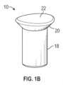
次に図1A~1Fを参照すれば、いくつかの実施形態では、1つまたは複数のセプタムストッパ10は、セプタム12をカテーテル組立体16のカテーテルアダプタ14内に固定するのを助けることができる。いくつかの実施形態では、セプタム12は、血液制御セプタムを含むことができる。セプタムストッパ10は、さまざまな形状およびサイズを含むことができる。いくつかの実施形態では、セプタムストッパ10のそれぞれは、シリンダ状底部分18および/または底部分18から外方向に突起するヘッド20を含むことができる。 Next, with reference to FIGS. 1A-1F, in some embodiments, one or
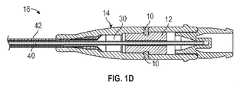
いくつかの実施形態では、セプタムストッパ10のそれぞれは、曲線状の上部表面22を含むことができる。たとえば、セプタムストッパ10のそれぞれは、凸状または凹状の上部表面22を含むことができる。いくつかの実施形態では、曲線状の上部表面22は、カテーテルアダプタ14の外側表面の湾曲に合致することができ、それにより、カテーテルアダプタ15の外側表面とセプタムストッパ10のそれぞれとの間に円滑な移行が存在する。図1D~1Eは、挿入構成にあるカテーテル組立体16を示し、ここでは導入針40が、カテーテルアダプタ14を通り、カテーテル42の遠位端部を超えて延びている。 In some embodiments, each of the
いくつかの実施形態では、セプタム12は、1つまたは複数の溝24を含むことができる。いくつかの実施形態では、溝24は、環状になり得る。いくつかの実施形態では、溝24は、カテーテルアダプタ14の壁28を通って延びる1つまたは複数のスロットまたはストッパ穴26と位置合わせされ得る。いくつかの実施形態では、ストッパ穴26のそれぞれは、特定のセプタムストッパ10を固定するようにサイズ設定され、構成され得る。たとえば、ストッパ穴26のそれぞれは、底部分18のサイズおよび形状に対応する内側部分、および/またはヘッド20のサイズおよび形状に対応する外側部分を含むことができる。 In some embodiments, the
いくつかの実施形態では、セプタムストッパ10は、溝24内にセプタムストッパ10のそれぞれの端部が配設されるようにストッパ穴26を通って延びることができ、セプタム12をカテーテルアダプタ14内に固定する。いくつかの実施形態では、セプタムストッパ10をストッパ穴26および/または溝24内にさらに固定するために、接着剤29を次の1つまたは複数に塗布することができる:ストッパ穴26、セプタムストッパ10,および溝24。 In some embodiments, the
いくつかの実施形態では、カテーテルアダプタ14は、たとえば図1Cに示すような、第1のストッパ穴26および第2のストッパ穴26を含むことができる。いくつかの実施形態では、第1のストッパ穴26および第2のストッパ穴26は、対向しており、カテーテルアダプタ14の両側に配設され得る。しかし、カテーテル組立体16は、任意の数のセプタムストッパ10および対応するストッパ穴26を含むことができる。たとえば、カテーテルアダプタ14は、3つまたは4つのストッパ穴26およびセプタムストッパ10を含むことができる。いくつかの実施形態では、ストッパ穴26をカテーテルアダプタ14の周囲に離間して置くことができ、および/または単一の環状溝24と位置合わせすることもできる。いくつかの実施形態では、ストッパ穴26は、セプタム12の周りの任意の場所に配設され得る。 In some embodiments, the
いくつかの実施形態では、セプタム12は、一体的に形成され得る。いくつかの実施形態では、セプタム12は、複数の部片または構成要素を含むことができる。いくつかの実施形態では、特定の溝24が、構成要素の交差部に形成され得る。セプタムストッパ10および/またはカテーテルアダプタ14に適した材料は、それだけに限定されないが、ポリカーボネート、ポリスチレン、ポリプロピレン、ポリカーボネート、ポリエチレンテレフタラートグリコール(PETG)、コポリエステルなどの熱可塑性ポリマー樹脂を含むことができる。セプタムストッパ10および/またはカテーテルアダプタ14に適した材料は、それだけに限定されないが、鋼、亜鉛、ニッケル、銀などを含むことができる。 In some embodiments, the
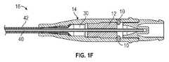
いくつかの実施形態では、カテーテル組立体16の組み立て中、セプタム12は、カテーテルアダプタ14の壁28を通って延びるストッパ穴26とセプタム12の溝24が位置合わせされるように、カテーテルアダプタ14の管腔30内に置かれ得る。いくつかの実施形態では、次いで、セプタムストッパ10をストッパ穴26内に置き、セプタムストッパ10の端部が溝24内にしっかりと嵌合してセプタム12をカテーテルアダプタ14に固定する。追加的または代替的に、いくつかの実施形態では、1つまたは複数のストッパ穴26をセプタム12の近位に配設することができ、ストッパ穴26内に配設されたセプタムストッパ10は、図1Fに示すように、セプタム12の近位端部の近位の管腔30内に延びることができる。いくつかの実施形態では、セプタムストッパ10は、セプタム12の近位端部に接触することができ、またはこれからわずかに離間して置かれてもよい。 In some embodiments, during assembly of the
いくつかの実施形態では、カテーテル組立体16が加圧されたとき、または流体がたとえば、ポート32を通って自動注射器によって高圧でカテーテルアダプタ14に注入されたとき、セプタムストッパ10は、セプタム12がカテーテルアダプタ14からずれることを防止することができる。いくつかの実施形態では、高圧は、300psi(2068kPa)以上になり得る。 In some embodiments, the
いくつかの実施形態では、カテーテル組立体は、静脈内(IV)カテーテルを含むことができる。いくつかの実施形態では、カテーテル組立体16は、一体的であっても非一体的であってもよい。セプタムストッパ10は、さまざまなタイプのカテーテル組立体、血管アクセスデバイス内で、さまざまなタイプのセプタムと共に使用され得ることが、理解される。いくつかの実施形態では、カテーテル組立体16は、BD INTIMA II(商標)IVカテーテル、BD NEXIVA(商標)DIFFUSICS(商標)クローズドIVカテーテルシステム、または別のカテーテル組立体に対応することができる。 In some embodiments, the catheter assembly can include an intravenous (IV) catheter. In some embodiments, the
次に図2Aを参照すれば、セプタムストッパ10に追加的または代替的に、いくつかの実施形態では、カテーテル組立体33は、セプタム12を固定するためにクリップまたはワッシャ34を含むことができる。いくつかの実施形態では、カテーテル組立体33は、図1のカテーテル組立体16を含むか、またはこれに対応することができる。いくつかの実施形態では、ワッシャ34は、U字形状になり得る。いくつかの実施形態では、ワッシャ34のアーム36は、互いに略平行になり得る。ワッシャ34および/またはカテーテルアダプタ14に適した材料は、それだけに限定されないが、ポリカーボネート、ポリスチレン、ポリプロピレン、ポリカーボネート、ポリエチレンテレフタラートグリコール(PETG)、コポリエステルなどの熱可塑性ポリマー樹脂を含むことができる。ワッシャ34および/またはカテーテルアダプタ14に適した材料は、それだけに限定されないが、鋼、亜鉛、ニッケル、銀などの金属を含むことができる。 Next, with reference to FIG. 2A, in addition or alternative to the
次に図2Bを参照すれば、いくつかの実施形態では、カテーテルアダプタ14は、カテーテルアダプタ14の壁28を通って延びることができる2つの穴38を含むことができる。いくつかの実施形態では、穴38のそれぞれは、ワッシャ34の特定のアーム36の端部を受け入れるようにサイズ設定され、構成され得る。2つの穴38の代替策として、いくつかの実施形態では、カテーテルアダプタの管腔30を形成する内壁は、ワッシャ34の特定のアーム36の端部を受け入れるようにそれぞれがサイズ設定され、構成され得る2つの溝を含むことができる。いくつかの実施形態では、アーム36の端部を穴38または溝内にさらに固定するために、接着剤29をアーム36の端部および/または穴38または溝の1つまたは複数に塗布することができる。 Next, referring to FIG. 2B, in some embodiments, the
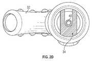
次に図2C~2Dを参照すれば、いくつかの実施形態では、ワッシャ34は、カテーテルアダプタ14の管腔30内の、セプタム12の近位端部の近位に配設され得る。いくつかの実施形態では、ワッシャ34は、カテーテルアダプタ14の管腔30内に、セプタム12の近位端部と接触して、またはセプタム12の近位端部から離間して配設され得る。いくつかの実施形態では、ワッシャ34は、たとえば高圧の流体の注入などの加圧に応答して発生し得る、近位方向へのセプタム12の強制に応答して、セプタム12の近位端部と接触し、および/またはこれに圧力をかけることができる。 Next, referring to FIGS. 2C-2D, in some embodiments, the
いくつかの実施形態では、カテーテル組立体33が、図2Cに示すような患者の血管系内に挿入する準備ができた挿入構成にあるとき、導入針40は、ワッシャ34の中央部分を通って、2つのアーム36間を延びることができる。図2Dに示すように、いくつかの実施形態では、針40は、ワッシャ34の中央部分を通って針40が延びるとき、ワッシャ34から離間して置かれ得る。いくつかの実施形態では、カテーテル組立体33が挿入構成にあるとき、針40は、セプタム12を通って延び、カテーテルアダプタ14に結合されたカテーテル42の遠位端部から延びることもできる。 In some embodiments, when the
いくつかの実施形態では、カテーテル42が血管系内に置かれたとき、カテーテル組立体33を、針40が後退される流体送達構成に移動させることができ、流体は、カテーテル42を通して患者の血管系に送達され得る。いくつかの実施形態では、自動注射器をポート32に結合させることができ、流体は、ポート32を介してカテーテルアダプタ14に流れ込むことができる。いくつかの実施形態では、ワッシャ34のアーム36を穴38内に配設することができ、ワッシャ34を流体送達構成および挿入構成の両方において管腔30内に固定することができる。 In some embodiments, when the
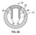
次に図2E~2Gを参照すれば、いくつかの実施形態では、ワッシャ34のアーム36の1つまたは複数は、セプタム12を貫通してセプタム12の固定を容易にすることができる先が尖った、または鋭利な要素39内で終端することができる。いくつかの実施形態では、鋭利な要素39は、図2Aに示すようなピン形状になり得る。いくつかの実施形態では、鋭利な要素39は、セプタム12を貫通してワッシャ34をセプタム12に固定するように構成され得る。いくつかの実施形態では、鋭利な要素39は、セプタム12の長さに沿ってさまざまな地点に配設され、高圧時に依然としてセプタム12を固定することができるため、鋭利な要素39は、セプタム12をそれほど正確に置かなくてもよい。いくつかの実施形態では、セプタム12は、弾性の可撓性材料から構築することができ、それによって鋭利な要素39によるセプタム12の貫通を容易にすることができる。たとえば、セプタム12は、シリコン、ポリイソプレン、ゴム、エラストマーポリマー、または別の材料から構築され得る。いくつかの実施形態では、カテーテルアダプタ14の壁28は、ワッシャ34のセプタム12内への挿入を可能にする1つまたは複数の開口41を含むことができる。いくつかの実施形態では、ワッシャ34の外側部分の湾曲は、壁34の外側表面の湾曲に合致することができ、それにより、カテーテルアダプタ14の外側表面にわたって円滑な移行が提供され得る。 Next, with reference to FIGS. 2E-2G, in some embodiments, one or more of the
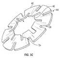
次に図3A~3Dを参照すれば、セプタムストッパ10に追加的または代替的に、いくつかの実施形態では、カテーテル組立体43は、セプタム12を固定するために別のタイプのワッシャ44を含むことができる。いくつかの実施形態では、カテーテル組立体43は、図1のカテーテル組立体16および/または図2のカテーテル組立体33を含むか、またはこれらに対応することができる。いくつかの実施形態では、ワッシャ44は、カテーテルアダプタ14の管腔30内の、セプタム12の近位に位置決めされ得る。いくつかの実施形態では、ワッシャ44は、弛緩状態において円錐状またはドーム形状になり得る。これらおよび他の実施形態では、ワッシャの内周または内側縁46は、ワッシャ44の外周または外側縁48の遠位にあることができる。 Then, with reference to FIGS. 3A-3D, in addition or alternative to the
いくつかの実施形態では、ワッシャ44は、たとえばカテーテルアダプタ14内への流体50の注入などを通して圧力をセプタム12にかける前に、弛緩状態で配設され得る。いくつかの実施形態では、圧力は、高圧または300psi(2068kPa)以上に対応することができる。いくつかの実施形態では、圧力をセプタム12にかける前、ワッシャ44の外側縁48はカテーテルアダプタ14の壁28に接触することができるが、カテーテルアダプタ14の壁28上にワッシャ44によって及ぼされる力は、公称または低いものになり得る。いくつかの実施形態では、公称圧力または低圧は、カテーテル組立体43の有効保存期間を増大させることができる。 In some embodiments, the
いくつかの実施形態では、圧力をセプタム12にかける前、ワッシャ44は、セプタム12に接触することができ、またはセプタム12とワッシャ34との間に空間を配設することができる。いくつかの実施形態では、圧力をセプタム12にかけたことに応答して、セプタム12は、近位方向にワッシャ44に接触し、および/または圧力をかけることができ、それによってワッシャ44を圧縮させるか、または応力状態で平坦にすることができる。ワッシャ44が圧縮したとき、ワッシャ44はその円錐またはドーム形状のいくらかまたはすべてを失い得る。いくつかの実施形態では、圧縮は、裸眼で見えても見えなくてもよい。いくつかの実施形態では、ワッシャ44を圧縮することにより、ワッシャ44の直径を増大させ、ワッシャ44がより大きな力をカテーテルアダプタ14の壁28上に及すようにすることができ、その結果、ワッシャ44は、圧力がセプタム12にかけられたとき、カテーテルアダプタ14内によりしっかりと保持され得る。 In some embodiments, the
いくつかの実施形態では、ワッシャ34は、ばね様または弾力性であり得る。いくつかの実施形態では、圧力がセプタム12にかけられなくなったとき、ワッシャ34は、自動的に元の円錐またはドーム形状に戻ることができ、カテーテルアダプタ14の壁28にかける力はより小さくなり得る。ワッシャ44に適した材料は、それだけに限定されないが、ポリカーボネート、ポリスチレン、ポリプロピレン、ポリカーボネート、ポリエチレンテレフタラートグリコール(PETG)、コポリエステルなどの熱可塑性ポリマー樹脂を含むことができる。ワッシャ44に適した材料は、それだけに限定されないが、鋼、亜鉛、ニッケル、銀などを含むことができる。 In some embodiments, the
いくつかの実施形態では、ワッシャ44の外側縁48は、1つまたは複数の内方向に延びるスロット54を含むことができる。追加的または代替的に、いくつかの実施形態では、ワッシャ44の内側縁46は、1つまたは複数の外方向に延びるスロット56を含むことができる。いくつかの実施形態では、スロット54および/またはスロット56は、セプタム12がワッシャ44のドーム形状に力をかけたことに応答して、ワッシャ44の圧縮または平坦化を容易にすることができる。ワッシャ44が圧縮されたとき、内側縁46は、外側縁48近くに移動し得る。いくつかの実施形態では、ワッシャ44は、接着剤、溶接または他の固定機構を使用せずに、たとえば注入による増大した圧力に応答してカテーテルアダプタ14の管腔30内にセプタム12を固定することができる。 In some embodiments, the
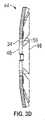
いくつかの実施形態では、内側縁46は、中央に配置することができ、カテーテル組立体43が挿入構成にあるときに導入針40がそこを通って延びることができる、ワッシャ44の開口59を画定することができる。いくつかの実施形態では、針40の外径は、内側縁46の直径より小さくなり得る。 In some embodiments, the
ワッシャ44の例示的な弛緩状態が、図3Aおよび図3C~3Dに示される。ワッシャ44の例示的な応力状態は、図3Bに示される。いくつかの実施形態では、ワッシャ44は、カテーテル組立体43が挿入構成にあるとき、弛緩状態で配設され得る。いくつかの実施形態では、針組立体60が取り除かれ、カテーテル組立体43が流体送達構成にあり、流体がカテーテルアダプタ14に流れ込んで近位力をセプタム12上に及ぼしたとき、ワッシャ44は応力状態で配設され得る。いくつかの実施形態では、流体50は、セプタム12をワッシャ44に対して近位に強制することができる。いくつかの実施形態では、内側縁46は、セプタムがワッシャ44に対して近位に強制されたことに応答して、外側縁48に向かって移動することができ、外側縁48は、静止し、壁28と接触したままになり得る。 Exemplary relaxed states of the
カテーテル組立体43は、任意の適切なタイプのセプタム12を含むことができる。次に図3E~3Fを参照すれば、いくつかの実施形態では、セプタム12は、図3A~3Dに関して論じたようなセプタム12と同様にワッシャ44に接触し、近位力をかけてワッシャ44を圧縮させることができる、ホルダまたはキャニスタ58内に配設され得る。いくつかの実施形態では、キャニスタ58は、図2A~2Dに関して論じたようなセプタム12と同様に、ワッシャ34に接触し、近位力をかけることができる。いくつかの実施形態では、セプタム12は、低効力セプタム12を含むことができる。いくつかの実施形態では、セプタムストッパ10は、図1A~1Dに関して開示したのと同様に、壁28を通ってキャニスタ58内に、またはキャニスタ58を通って延びることができる。 The
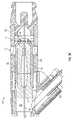
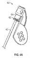
次に図4A~4Bを参照すれば、いくつかの実施形態では、カテーテル組立体61の針組立体60の近位端部は、カテーテルアダプタ14内に配設されたセプタム12を固定するように構成され得る保持ディスク62を含むことができる。いくつかの実施形態では、カテーテル組立体61は、次の1つまたは複数を含むか、またはこれに対応することができる:図1のカテーテル組立体16、図2のカテーテル組立体33、または図3のカテーテル組立体43。いくつかの実施形態では、保持ディスク62は、1つまたは複数の破損可能なアーム64によって針組立体60の一部分に連結され得る。いくつかの実施形態では、針組立体60のその部分は、針組立体60の針ハブ66を含むことができる。換言すれば、アーム64は、保持ディスク62と針ハブ66との間を延びることができる。いくつかの実施形態では、針40の近位端部は、針ハブ66内に固定され得る。 Next, referring to FIGS. 4A-4B, in some embodiments, the proximal end of the
いくつかの実施形態では、任意の数のアーム64が、保持ディスク62と針組立体60のその部分との間を延びることができる。いくつかの実施形態では、第1のアーム64aおよび第2のアーム64b(本開示では、「アーム」と称され得る)は、針組立体60の両側に配設され得る。いくつかの実施形態では、針組立体60は、アーム64を通って延びる脆弱線68を備えて成形され得る。いくつかの実施形態では、脆弱線68は、アーム64の窪められたまたはより薄い部分を含むことができる。 In some embodiments, any number of
いくつかの実施形態では、保持ディスク62は、保持ディスク62をカテーテルアダプタ14の壁28に結合するための結合機構を含むことができる。結合機構は、任意の適切な結合機構を含むことができる。たとえば、保持ディスク62は、1つまたは複数の翼部70を含むことができ、この翼部は、壁28内の対応する溝または開口部72内にスナップ嵌合するか、またはこれを干渉するようにサイズ設定され構成され得る。いくつかの実施形態では、保持ディスク62は、第1の翼部70aと、第2の翼部70bとを含むことができる。別の例として、保持ディスク62は、カテーテルアダプタ14の壁28の1つまたは複数のねじ山に対応することができる1つまたは複数のねじ山を含むことができる。 In some embodiments, the
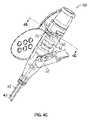
次に図4Cを参照すれば、いくつかの実施形態では、針組立体60および保持ディスク62は、カテーテルアダプタ14の近位端部内に挿入され、結合機構を介してカテーテルアダプタ14に結合され得る。たとえば、針組立体60は、保持ディスク62の翼部70が壁28内の開口部72または溝に位置合わせされるようにカテーテルアダプタ14の近位端部に挿入され得る。したがって、保持ディスク62および針組立体60は、カテーテルアダプタ14内に固定され得る。 Next, referring to FIG. 4C, in some embodiments, the
いくつかの実施形態では、保持ディスク62がカテーテルアダプタ14内に固定された後、針組立体60の近位部分をカテーテルアダプタ14に対してねじるか、または回転させることができ、それによってアーム64が脆弱線68に沿って破損するようにすることができる。いくつかの実施形態では、アーム64の破損に応答して、針組立体60の近位部分を、カテーテルアダプタ14およびカテーテルアダプタ14に固定されたままであり得る保持ディスク62から分離させることができる。 In some embodiments, after the
いくつかの実施形態では、保持ディスク62は、たとえば注入による増大した圧力に応答して、セプタム12をカテーテルアダプタ14内に保持するか、または固定することができる。いくつかの実施形態では、増大した圧力は、300psi(2068kPa)以上になり得る。いくつかの実施形態では、保持ディスク62は、増大した圧力に応答して、セプタム12の近位端部またはセプタム12のキャニスタ58に接触し、および/または圧力をかけることができる。したがって、保持ディスク62は、セプタム12がずれること、または流体構成においてカテーテルアダプタ14の近位端部から出ることを防止することができる。 In some embodiments, the
図4Dは、例示の目的のための、いくつかの実施形態による、針組立体60の近位部分から分離された保持ディスク62の拡大された下側斜視図である。図4Eは、いくつかの実施形態による、図4Cの線4E-4Eを横断するカテーテル組立体61の断面図である。図4Eは、針40がセプタム12を通って近位に引き出された後の、流体送達構成にあるカテーテル組立体61を示す。図4D~4Eに示すように、保持ディスク62は、リング形状であってもよく、および/または針40がそこを通って延びることができる中央開口を含むことができる。 FIG. 4D is an enlarged lower perspective view of the holding
本発明は、その構造、方法、または本明細書において広範に説明し、特許請求する他の本質的な特性から逸脱することなく、他の特有の形態で具現化され得る。図1~4に関して論じるカテーテル組立体は、追加の要素および/または構成要素を含むことができる。図1~4に関して論じるカテーテル組立体は、さまざまなタイプの針安全機構を含むことができる。セプタムストッパ10、ワッシャ34、ワッシャ44、および保持ディスク62は、さまざまなタイプのカテーテル組立体、血管アクセス装置内で、さまざまなタイプのセプタムと共に使用され得ることが、理解される。説明する実施形態および例は、あらゆる点において単に例示的であり、制限的ではないと考えられるものとする。したがって、本発明の範囲は、前述の説明ではなく、付属の特許請求の範囲によって示される。特許請求の範囲の等価性の意味および範囲内に入るすべての変更は、その範囲に包含されるものとする。 The present invention may be embodied in other specific forms without departing from its structure, method, or other essential properties that are broadly described and claimed herein. The catheter assembly discussed with respect to FIGS. 1-4 can include additional and / or components. The catheter assembly discussed with respect to FIGS. 1-4 can include various types of needle safety mechanisms. It is understood that the
Claims (13)
Translated fromJapanese近位端部と、遠位端部と、それらの間に延びる管腔とを備えるカテーテルアダプタであって、前記遠位端部が、患者の血管系に挿入されるように構成されたカテーテルを備える、カテーテルアダプタと、
前記管腔内に配設されたセプタムと、
セプタム固定要素と、を備え、前記セプタム固定要素が前記セプタムの遠位端部の近位に配設され、前記セプタム固定要素が前記セプタムへの近位力に応答して前記セプタムを固定するように構成されており、
前記セプタム固定要素がセプタムストッパを備え、前記セプタムストッパは前記カテーテルアダプタの壁を通って延び、前記セプタムストッパがシリンダ状底部分とヘッドとを備え、前記ヘッドが前記シリンダ状底部分より大きい直径を有する、カテーテル組立体。It ’s a catheter assembly,
A catheter adapter comprising a proximal end, a distal end, and a lumen extending between them, wherein the distal end is configured to be inserted into the patient's vasculature. Equipped with a catheter adapter and
With the septum disposed in the lumen,
With a septum fixing element, the septum fixing element is disposed proximal to the distal end of the septum so that the septum fixing element secures the septum in response to a proximal force to the septum. Is configured in
The septum fixing element comprises a septum stopper, the septum stopper extends through the wall of the catheter adapter, the septum stopper comprises a cylindrical bottom portion and a head, and the head has a larger diameter than the cylindrical bottom portion. Havea catheter assembly.
近位端部と、遠位端部と、それらの間に延びる管腔とを備えるカテーテルアダプタであって、前記遠位端部が、患者の血管系に挿入されるように構成されたカテーテルを備える、カテーテルアダプタと、
前記管腔内に配設されたセプタムと、
セプタム固定要素と、を備え、前記セプタム固定要素が前記セプタムの遠位端部の近位に配設され、前記セプタム固定要素が前記セプタムへの近位力に応答して前記セプタムを固定するように構成されており、
前記カテーテルアダプタを通って延びる導入針と、
前記管腔内かつ前記セプタムの近位に配設されたワッシャとをさらに備え、前記ワッシャが、離間して置かれていてU字形状を形成する2つのアームを含み、前記アームのそれぞれの端部が前記カテーテルアダプタ内の溝または穴内に配設され、前記導入針が前記2つのアーム間を延びている、カテーテル組立体。It ’s a catheter assembly,
A catheter adapter comprising a proximal end, a distal end, and a lumen extending between them, wherein the distal end is configured to be inserted into the patient's vasculature. Equipped with a catheter adapter and
With the septum disposed in the lumen,
With a septum fixing element, the septum fixing element is disposed proximal to the distal end of the septum so that the septum fixing element secures the septum in response to a proximal force to the septum. Is configured in
An introduction needle extending through the catheter adapter and
Further comprising a washer disposed in the lumen and proximal to the septum, the washer comprises two arms that are spaced apart to form a U-shape, each end of the arm. Acatheter assembly in which a portion is disposed in a groove or hole in the catheter adapter and the introduction needle extends between the two arms.
近位端部と、遠位端部と、それらの間に延びる管腔とを備えるカテーテルアダプタであって、前記遠位端部は、患者の血管系に挿入されるように構成されたカテーテルを備える、カテーテルアダプタと、
前記管腔内に配設されたセプタムと、
前記管腔内かつ前記セプタムの近位に配設されたワッシャと、を備え、前記ワッシャが円錐形状を有し、
前記セプタムへの近位方向の力に応答して、前記円錐形状が圧縮し前記ワッシャが前記カテーテルアダプタの内壁上により大きい力を及ぼす、カテーテル組立体。It ’s a catheter assembly,
A catheter adapter comprising a proximal end, a distal end, and a lumen extending between them, wherein the distal end is a catheter configured to be inserted into the patient's vasculature. Equipped with a catheter adapter and
With the septum disposed in the lumen,
With a washer disposed in the lumen and proximal to the septum, the washer has a conical shape.
Acatheter assembly in which the conical shape compresses and the washer exerts a greater force on the inner wall of the catheter adapter in response to a proximal force on the septum.
近位端部と、遠位端部と、それらの間に延びる管腔とを備えるカテーテルアダプタであって、前記遠位端部は、患者の血管系に挿入されるように構成されたカテーテルを備える、カテーテルアダプタと、
前記管腔内に配設されたセプタムと、
前記管腔内かつ前記セプタムの近位に配設されたワッシャと、を備え、前記ワッシャが円錐形状を有し、
前記ワッシャは、内側縁と、外側縁とを備え、前記外側縁の全体は、前記カテーテルアダプタの内壁に接触し、
前記内側縁は、複数の外方向に延びるスロットを備える、カテーテル組立体。It ’s a catheter assembly,
A catheter adapter comprising a proximal end, a distal end, and a lumen extending between them, wherein the distal end is a catheter configured to be inserted into the patient's vasculature. Equipped with a catheter adapter and
With the septum disposed in the lumen,
With a washer disposed in the lumen and proximal to the septum, the washer has a conical shape.
The washer comprises an inner edge and an outer edge, the entire outer edge of which contacts the inner wall of the catheter adapter.
The medial edge isa catheter assembly comprising a plurality of outwardly extending slots.
近位端部と、遠位端部と、それらの間に延びる管腔とを備えるカテーテルアダプタであって、前記遠位端部は、患者の血管系に挿入されるように構成されたカテーテルを備える、カテーテルアダプタと、
前記管腔内に配設されたセプタムと、
前記管腔内かつ前記セプタムの近位に配設されたワッシャと、を備え、前記ワッシャが円錐形状を有し、
前記ワッシャは、内側縁と、外側縁とを備え、前記外側縁の全体は、前記カテーテルアダプタの内壁に接触し、
前記外側縁は、複数の内方向に延びるスロットを備える、カテーテル組立体。It ’s a catheter assembly,
A catheter adapter comprising a proximal end, a distal end, and a lumen extending between them, wherein the distal end is a catheter configured to be inserted into the patient's vasculature. Equipped with a catheter adapter and
With the septum disposed in the lumen,
With a washer disposed in the lumen and proximal to the septum, the washer has a conical shape.
The washer comprises an inner edge and an outer edge, the entire outer edge of which contacts the inner wall of the catheter adapter.
The outer edge isa catheter assembly comprising a plurality of inwardly extending slots.
Priority Applications (1)
| Application Number | Priority Date | Filing Date | Title |
|---|---|---|---|
| JP2022017969AJP7325559B2 (en) | 2017-06-08 | 2022-02-08 | septum fixation |
Applications Claiming Priority (3)
| Application Number | Priority Date | Filing Date | Title |
|---|---|---|---|
| US15/617,646US10512755B2 (en) | 2017-06-08 | 2017-06-08 | Septum securement |
| US15/617,646 | 2017-06-08 | ||
| PCT/US2018/034899WO2018226453A2 (en) | 2017-06-08 | 2018-05-29 | Septum securement |
Related Child Applications (1)
| Application Number | Title | Priority Date | Filing Date |
|---|---|---|---|
| JP2022017969ADivisionJP7325559B2 (en) | 2017-06-08 | 2022-02-08 | septum fixation |
Publications (2)
| Publication Number | Publication Date |
|---|---|
| JP2020523108A JP2020523108A (en) | 2020-08-06 |
| JP7065891B2true JP7065891B2 (en) | 2022-05-12 |
Family
ID=62683448
Family Applications (2)
| Application Number | Title | Priority Date | Filing Date |
|---|---|---|---|
| JP2019568086AActiveJP7065891B2 (en) | 2017-06-08 | 2018-05-29 | Septum fixed |
| JP2022017969AActiveJP7325559B2 (en) | 2017-06-08 | 2022-02-08 | septum fixation |
Family Applications After (1)
| Application Number | Title | Priority Date | Filing Date |
|---|---|---|---|
| JP2022017969AActiveJP7325559B2 (en) | 2017-06-08 | 2022-02-08 | septum fixation |
Country Status (9)
| Country | Link |
|---|---|
| US (2) | US10512755B2 (en) |
| EP (2) | EP4344725A3 (en) |
| JP (2) | JP7065891B2 (en) |
| CN (2) | CN114377248B (en) |
| AU (1) | AU2018282000B2 (en) |
| CA (1) | CA3065192A1 (en) |
| MX (1) | MX2019014358A (en) |
| SG (1) | SG10202105340VA (en) |
| WO (1) | WO2018226453A2 (en) |
Cited By (1)
| Publication number | Priority date | Publication date | Assignee | Title |
|---|---|---|---|---|
| JP2022051879A (en)* | 2017-06-08 | 2022-04-01 | ベクトン・ディキンソン・アンド・カンパニー | Septum fixed |
Families Citing this family (6)
| Publication number | Priority date | Publication date | Assignee | Title |
|---|---|---|---|---|
| US10773056B2 (en) | 2017-03-21 | 2020-09-15 | Velano Vascular, Inc. | Systems and methods for controlling catheter device size |
| KR102573751B1 (en) | 2017-03-21 | 2023-09-04 | 벨라노 바스큘라, 인크. | Devices and methods for fluid delivery through a deployed peripheral intravenous catheter |
| JP7264819B2 (en) | 2017-09-29 | 2023-04-25 | テルモ株式会社 | catheter assembly |
| CN119185741A (en) | 2019-08-20 | 2024-12-27 | 威蓝诺血管股份有限公司 | Fluid delivery device with elongate conduit and method of use thereof |
| US20210299429A1 (en)* | 2020-03-31 | 2021-09-30 | Becton, Dickinson And Company | Catheter assembly with a slidable septum and related systems and methods |
| JP2024504631A (en)* | 2021-01-15 | 2024-02-01 | ベクトン・ディキンソン・アンド・カンパニー | Blood collection assembly and related devices and methods |
Citations (5)
| Publication number | Priority date | Publication date | Assignee | Title |
|---|---|---|---|---|
| JP2004528127A (en) | 2001-05-25 | 2004-09-16 | ベクトン・ディキンソン・アンド・カンパニー | Catheter with low resistance septum |
| JP2009513267A (en) | 2005-10-25 | 2009-04-02 | ベクトン・ディキンソン・アンド・カンパニー | Integrated low resistance bulkhead |
| CN202620440U (en) | 2012-03-02 | 2012-12-26 | 碧迪控股有限公司 | Catheter and intubator needle assembly |
| JP2013535249A (en) | 2010-07-15 | 2013-09-12 | ベクトン・ディキンソン・アンド・カンパニー | Detachable flash chamber |
| US20150151088A1 (en) | 2013-12-04 | 2015-06-04 | B. Braun Melsungen Ag | Catheter assembly with reusable valve |
Family Cites Families (23)
| Publication number | Priority date | Publication date | Assignee | Title |
|---|---|---|---|---|
| US4929235A (en) | 1985-07-31 | 1990-05-29 | Universal Medical Instrument Corp. | Self-sealing percutaneous tube introducer |
| US5000745A (en)* | 1988-11-18 | 1991-03-19 | Edward Weck Incorporated | Hemostatis valve |
| US6632200B2 (en) | 2000-01-25 | 2003-10-14 | St. Jude Medical, Daig Division | Hemostasis valve |
| US7347853B2 (en)* | 2004-05-12 | 2008-03-25 | C. R. Bard, Inc. | Catheter with removable extension |
| WO2006127123A2 (en)* | 2005-05-20 | 2006-11-30 | Medtronic, Inc. | Locking catheter connector and method |
| US7691090B2 (en)* | 2005-10-11 | 2010-04-06 | Tyco Healthcare Group Lp | IV catheter with in-line valve and methods related thereto |
| US20080249475A1 (en)* | 2006-02-22 | 2008-10-09 | Applied Medical Resources Corporation | Trocar seal |
| US8257313B2 (en)* | 2006-08-11 | 2012-09-04 | Becton, Dickinson And Company | Integrated septum and needle tip shield for a catheter assembly |
| WO2009041523A1 (en)* | 2007-09-27 | 2009-04-02 | Terumo Kabushiki Kaisha | Valve element and medical instrument |
| US9101748B2 (en)* | 2008-05-08 | 2015-08-11 | Becton, Dickinson And Company | Push-button blood control |
| US8679063B2 (en)* | 2009-02-11 | 2014-03-25 | Becton, Dickinson And Company | Systems and methods for providing a catheter assembly |
| US8932259B2 (en)* | 2010-09-13 | 2015-01-13 | Becton, Dickinson And Company | Catheter assembly |
| AU2013206101A1 (en)* | 2011-03-08 | 2013-06-20 | Covidien Lp | Catheter with valve |
| US9358364B2 (en) | 2011-10-06 | 2016-06-07 | Becton, Dickinson And Company | Activator attachment for blood control catheters |
| EP2827935B1 (en)* | 2012-03-18 | 2018-01-10 | Traumatek Solutions B.V. | Devices for endovascular access and therapy |
| JP6083850B2 (en)* | 2012-08-24 | 2017-02-22 | 株式会社グッドマン | Medical valve device |
| US10500376B2 (en) | 2013-06-07 | 2019-12-10 | Becton, Dickinson And Company | IV catheter having external needle shield and internal blood control septum |
| JP2015019546A (en)* | 2013-07-12 | 2015-01-29 | 株式会社東芝 | Axial gap type permanent magnet rotating electric machine and manufacturing method thereof |
| CN103736195B (en)* | 2014-01-13 | 2018-07-03 | 厦门鑫康顺医疗科技有限公司 | A kind of sterile catheter sheath |
| US9895525B2 (en)* | 2014-01-21 | 2018-02-20 | Becton, Dickinson And Company | Ported catheter adapter with integrated septum actuator retention |
| US9987477B2 (en)* | 2014-02-10 | 2018-06-05 | Nexus Medical, Llc | Split septum assembly for an intravenous injection site |
| US9931489B2 (en) | 2015-05-12 | 2018-04-03 | Medtronic Vascular, Inc. | Cross slit gasket for introducer sheath |
| US10512755B2 (en)* | 2017-06-08 | 2019-12-24 | Becton, Dickinson And Company | Septum securement |
- 2017
- 2017-06-08USUS15/617,646patent/US10512755B2/enactiveActive
- 2018
- 2018-05-29CNCN202210052100.3Apatent/CN114377248B/enactiveActive
- 2018-05-29AUAU2018282000Apatent/AU2018282000B2/enactiveActive
- 2018-05-29CACA3065192Apatent/CA3065192A1/enactivePending
- 2018-05-29SGSG10202105340VApatent/SG10202105340VA/enunknown
- 2018-05-29EPEP24157878.0Apatent/EP4344725A3/enactivePending
- 2018-05-29CNCN201880047740.7Apatent/CN110913939B/enactiveActive
- 2018-05-29JPJP2019568086Apatent/JP7065891B2/enactiveActive
- 2018-05-29MXMX2019014358Apatent/MX2019014358A/enunknown
- 2018-05-29WOPCT/US2018/034899patent/WO2018226453A2/ennot_activeCeased
- 2018-05-29EPEP18732555.0Apatent/EP3634560B1/enactiveActive
- 2019
- 2019-11-18USUS16/687,341patent/US11628273B2/enactiveActive
- 2022
- 2022-02-08JPJP2022017969Apatent/JP7325559B2/enactiveActive
Patent Citations (5)
| Publication number | Priority date | Publication date | Assignee | Title |
|---|---|---|---|---|
| JP2004528127A (en) | 2001-05-25 | 2004-09-16 | ベクトン・ディキンソン・アンド・カンパニー | Catheter with low resistance septum |
| JP2009513267A (en) | 2005-10-25 | 2009-04-02 | ベクトン・ディキンソン・アンド・カンパニー | Integrated low resistance bulkhead |
| JP2013535249A (en) | 2010-07-15 | 2013-09-12 | ベクトン・ディキンソン・アンド・カンパニー | Detachable flash chamber |
| CN202620440U (en) | 2012-03-02 | 2012-12-26 | 碧迪控股有限公司 | Catheter and intubator needle assembly |
| US20150151088A1 (en) | 2013-12-04 | 2015-06-04 | B. Braun Melsungen Ag | Catheter assembly with reusable valve |
Cited By (2)
| Publication number | Priority date | Publication date | Assignee | Title |
|---|---|---|---|---|
| JP2022051879A (en)* | 2017-06-08 | 2022-04-01 | ベクトン・ディキンソン・アンド・カンパニー | Septum fixed |
| JP7325559B2 (en) | 2017-06-08 | 2023-08-14 | ベクトン・ディキンソン・アンド・カンパニー | septum fixation |
Also Published As
| Publication number | Publication date |
|---|---|
| WO2018226453A3 (en) | 2019-01-17 |
| JP2022051879A (en) | 2022-04-01 |
| US20180353729A1 (en) | 2018-12-13 |
| AU2018282000B2 (en) | 2023-10-05 |
| CN114377248A (en) | 2022-04-22 |
| EP4344725A2 (en) | 2024-04-03 |
| EP3634560C0 (en) | 2024-04-03 |
| US11628273B2 (en) | 2023-04-18 |
| SG10202105340VA (en) | 2021-07-29 |
| JP7325559B2 (en) | 2023-08-14 |
| US10512755B2 (en) | 2019-12-24 |
| MX2019014358A (en) | 2020-01-23 |
| CN110913939B (en) | 2022-02-11 |
| US20200078556A1 (en) | 2020-03-12 |
| NZ759821A (en) | 2025-05-02 |
| EP4344725A3 (en) | 2024-07-10 |
| EP3634560A2 (en) | 2020-04-15 |
| CN114377248B (en) | 2024-09-03 |
| WO2018226453A2 (en) | 2018-12-13 |
| EP3634560B1 (en) | 2024-04-03 |
| CA3065192A1 (en) | 2018-12-13 |
| BR112019025936A2 (en) | 2020-06-30 |
| JP2020523108A (en) | 2020-08-06 |
| CN110913939A (en) | 2020-03-24 |
| AU2018282000A1 (en) | 2020-01-02 |
Similar Documents
| Publication | Publication Date | Title |
|---|---|---|
| JP7065891B2 (en) | Septum fixed | |
| CN107913444B (en) | Conduit assembly | |
| RU2763749C2 (en) | Devices and methods for moving fluid through installed peripheral intravenous catheter | |
| JP6297610B2 (en) | Catheter assembly with valve | |
| KR920000464B1 (en) | Single-use syringe | |
| US20040049163A1 (en) | Protector and storage needle assembly | |
| NO314246B1 (en) | Ring valve medical valve and the method of transferring a fluid through a medical valve | |
| NO314245B1 (en) | Medical valve with fluid escape room | |
| US11779744B2 (en) | Hemostasis valve assembly and Method for assembling a hemostasis valve | |
| CN104043180A (en) | Valved catheter assemblies and related methods | |
| JP2016013359A (en) | Hub assembly with bulkhead member | |
| BR112019025936B1 (en) | CATHETER MOUNTS |
Legal Events
| Date | Code | Title | Description |
|---|---|---|---|
| A621 | Written request for application examination | Free format text:JAPANESE INTERMEDIATE CODE: A621 Effective date:20210219 | |
| A977 | Report on retrieval | Free format text:JAPANESE INTERMEDIATE CODE: A971007 Effective date:20211029 | |
| A131 | Notification of reasons for refusal | Free format text:JAPANESE INTERMEDIATE CODE: A131 Effective date:20211109 | |
| A521 | Request for written amendment filed | Free format text:JAPANESE INTERMEDIATE CODE: A523 Effective date:20220208 | |
| TRDD | Decision of grant or rejection written | ||
| A01 | Written decision to grant a patent or to grant a registration (utility model) | Free format text:JAPANESE INTERMEDIATE CODE: A01 Effective date:20220405 | |
| A61 | First payment of annual fees (during grant procedure) | Free format text:JAPANESE INTERMEDIATE CODE: A61 Effective date:20220426 | |
| R150 | Certificate of patent or registration of utility model | Ref document number:7065891 Country of ref document:JP Free format text:JAPANESE INTERMEDIATE CODE: R150 | |
| R250 | Receipt of annual fees | Free format text:JAPANESE INTERMEDIATE CODE: R250 |