JP7064711B2 - Photo image printing system - Google Patents
Photo image printing systemDownload PDFInfo
- Publication number
- JP7064711B2 JP7064711B2JP2018042313AJP2018042313AJP7064711B2JP 7064711 B2JP7064711 B2JP 7064711B2JP 2018042313 AJP2018042313 AJP 2018042313AJP 2018042313 AJP2018042313 AJP 2018042313AJP 7064711 B2JP7064711 B2JP 7064711B2
- Authority
- JP
- Japan
- Prior art keywords
- display panel
- power
- power supply
- control unit
- line
- Prior art date
- Legal status (The legal status is an assumption and is not a legal conclusion. Google has not performed a legal analysis and makes no representation as to the accuracy of the status listed.)
- Active
Links
Images


Landscapes
- Accessory Devices And Overall Control Thereof (AREA)
- Control Or Security For Electrophotography (AREA)
- Facsimiles In General (AREA)
Description
Translated fromJapanese本発明は写真画像プリントシステムに係り、とりわけ効果的に省電力を図ることができる写真画像プリントシステムに関する。 The present invention relates to a photographic image printing system, and particularly relates to a photographic image printing system capable of effectively saving power.
従来より写真画像プリントシステムとして、筐体と、筐体に設けられた表示パネルと、筐体内に収納されたプリンタおよび課金システムとを備えたものが知られている。 Conventionally, as a photographic image printing system, a system including a housing, a display panel provided in the housing, a printer housed in the housing, and a billing system is known.
使用にあたって操作者は、写真画像プリントシステムの媒体挿入口に必要な画像情報を格納したデジタルメディア、例えばSD(secure digital)カード、CD-ROM等を挿入し、表示パネル上で必要な情報を入力する。 In use, the operator inserts a digital medium containing necessary image information, such as an SD (secure digital) card or CD-ROM, into the medium insertion slot of the photographic image printing system, and inputs the necessary information on the display panel. do.
その後、操作者は課金システムに接続された筐体の前面扉に設けられたコイン投入口へ必要な額のコインを投入する。操作者がコインを投入した後、プリンタが写真画像をプリントして写真画像印刷物を作成し、この写真画像印刷物は前面扉から排出される。 After that, the operator inserts the required amount of coins into the coin slot provided on the front door of the housing connected to the billing system. After the operator inserts the coin, the printer prints a photographic image to create a photographic image printed matter, and the photographic image printed matter is ejected from the front door.
このような写真画像プリントシステムにおいて、操作者が操作するか否かにかかわらず、筐体に設けられた表示パネルおよびプリンタ等の構成部分には常時電力が供給され、電力料金が嵩んでしまう。 In such a photographic image printing system, electric power is constantly supplied to the components such as the display panel and the printer provided in the housing regardless of whether or not the operator operates the system, and the electric power charge increases.
一方、写真画像プリントシステムに人感センサを設け、人が接近した場合に省電力モードから通常運転モードに切り換えて、省電力を図る技術が開発されているが、この場合、写真画像プリントシステムに通行人が接近しただけで写真画像プリントシステムが通常運転モードをとってしまうため、十分な省電力効果を実施することはむずかしい。 On the other hand, a technique has been developed in which a human sensor is provided in a photographic image printing system to switch from a power saving mode to a normal operation mode when a person approaches to save power. In this case, the photographic image printing system has been developed. It is difficult to achieve a sufficient power saving effect because the photographic image printing system takes the normal operation mode just by approaching a passerby.
本発明はこのような点を考慮してなされたものであり、省電力運転を確実に実行することができる写真画像プリントシステムを提供することを目的とする。 The present invention has been made in consideration of such a point, and an object of the present invention is to provide a photographic image printing system capable of reliably performing power-saving operation.
本発明は、筐体と、前記筐体に設けられた操作可能な表示パネルと、前記筐体に設けられたプリンタと、前記筐体に設けられ、視線を検知する視線センサと、前記筐体に配置され、前記表示パネルによって入力された操作信号に基づいて前記プリンタにより写真画像印刷物を作成する操作制御部と、前記表示パネルおよび前記プリンタへの電力供給を制御する電力供給制御部とを備え、前記電力供給制御部は、前記視線センサからの信号に基づいて、視線を検知した場合に通常運転モードをとって、前記表示パネルおよび前記プリンタへの電力を供給し、視線を検知しない場合に省電力モードをとって少なくとも前記表示パネルへの電力供給を制限する、写真画像プリントシステムである。 The present invention includes a housing, an operable display panel provided in the housing, a printer provided in the housing, a line-of-sight sensor provided in the housing to detect a line of sight, and the housing. It is provided with an operation control unit for creating a photographic image print by the printer based on an operation signal input by the display panel, and a power supply control unit for controlling the power supply to the display panel and the printer. When the power supply control unit takes a normal operation mode when it detects a line of sight based on a signal from the line-of-sight sensor, it supplies power to the display panel and the printer, and does not detect the line of sight. It is a photographic image printing system that takes a power saving mode and limits the power supply to at least the display panel.
本発明は、前記電力供給制御部は、前記視線センサからの信号を所定時間以上連続して受信した後で、前記通常運転モードまたは前記省電力モードのいずれかをとる、写真画像プリントシステムである。 The present invention is a photographic image printing system in which the power supply control unit takes either the normal operation mode or the power saving mode after continuously receiving a signal from the line-of-sight sensor for a predetermined time or longer. ..
本発明は、前記筐体に人を検知する人感センサが設けられ、前記電力供給制御部は、前記人感センサおよび前記視線センサからの信号に基づいて、人を検知しかつ視線を検知した場合に前記通常運転モードをとり、人を検知せずかつ視線を検知しない場合に前記省電力モードをとる、写真画像プリントシステムである。 In the present invention, a motion sensor for detecting a person is provided in the housing, and the power supply control unit detects a person and detects a line of sight based on signals from the motion sensor and the line-of-sight sensor. This is a photographic image printing system that takes the normal operation mode in some cases and takes the power saving mode when it does not detect a person and does not detect a line of sight.
本発明は、前記電力供給制御部は、前記人感センサおよび前記視線センサからの信号に基づいて、人を検知し、その後に視線を検知した場合に前記通常運転モードをとり、視線を検知せず、その後に人を検知しない場合に前記省電力モードをとる、写真画像プリントシステムである。 In the present invention, the power supply control unit detects a person based on the signals from the motion sensor and the line-of-sight sensor, and when the line of sight is subsequently detected, takes the normal operation mode and detects the line of sight. It is a photographic image printing system that takes the power saving mode when no person is detected after that.
本発明は、前記電力供給制御部の前記省電力モードは、省電力モードAと省電力モードBとからなり、前記電力供給制御部は、前記人感センサおよび前記視線センサからの信号に基づいて、前記表示パネルへの電力供給を停止する前記省電力モードAの状態で人を検知した場合に前記表示パネルへ一部電力供給を行う前記省電力モードBをとり、その後に視線を検知した場合に前記通常運転モードをとり、前記通常運転モードの状態で視線を検知しない場合に前記省電力モードBをとり、その後に人を検知しない場合に前記省電力モードAをとる、写真画像プリントシステムである。 In the present invention, the power saving mode of the power supply control unit includes a power saving mode A and a power saving mode B, and the power supply control unit is based on signals from the human sensor and the line-of-sight sensor. When a person is detected in the power saving mode A in which the power supply to the display panel is stopped, the power saving mode B in which a part of the power is supplied to the display panel is taken, and then the line of sight is detected. In a photographic image printing system, the normal operation mode is taken, the power saving mode B is taken when the line of sight is not detected in the normal operation mode, and then the power saving mode A is taken when no person is detected. be.
本発明は、前記表示パネルは第1表示パネルと第2表示パネルを有し、前記電力供給制御部は通常運転モードをとった際、前記第1表示パネルおよび前記第2表示パネルへの電力供給をONとし、前記省電力モードをとった際、前記第1表示パネルへの電力供給をONとし、前記第2表示パネルへの電力供給をOFFとする、写真画像プリントシステムである。 In the present invention, the display panel has a first display panel and a second display panel, and when the power supply control unit takes a normal operation mode, power is supplied to the first display panel and the second display panel. This is a photographic image printing system that turns on the power supply to the first display panel and turns off the power supply to the second display panel when the power saving mode is taken.
以上のように本発明によれば、省電力運転を確実に実行することができる。 As described above, according to the present invention, the power saving operation can be reliably executed.
<第1の実施の形態>
以下、図面を参照して本発明による写真画像プリントシステムについて図1乃至図4により説明する。<First Embodiment>
Hereinafter, the photographic image printing system according to the present invention will be described with reference to FIGS. 1 to 4.
図1乃至図4は写真画像プリントシステムの第1の実施の形態を示す図である。 1 to 4 are diagrams showing a first embodiment of a photographic image printing system.
ここで図1は写真画像プリントシステムを前方側からみた概略斜視図であり、図2は写真画像プリントシステムの制御機構を示すブロック図である。 Here, FIG. 1 is a schematic perspective view of the photographic image printing system as viewed from the front side, and FIG. 2 is a block diagram showing a control mechanism of the photographic image printing system.
図1乃至図4に示すように、本発明による写真画像プリントシステム10は、天板11aと、一対の側方側板11b,11bと、背面側板と、底板とを有する筐体11と、筐体11の天板11a上の後方に配置され、後述する操作制御部31と電力供給制御部32とが内蔵されたパーソナルコンピューター(PC)20と、筐体11内に収納された2台のプリンタ15,15と、課金システム8とを備えている。 As shown in FIGS. 1 to 4, the photographic
このうち筐体11は上述のように天板11aと、一対の側方側板11b,11bと、背面側板と底板とを有し、筐体11内は、筐体11内をプリンタ15を収納するプリンタ収納領域6aと、課金システム8を収納する課金システム収納領域6bとに区画されている。また筐体11の前面左側には前面扉12が設けられ、筐体11の前面右側には、上方から下方に向かって順にコイン投入口18a、お札投入口18bおよびつり銭返却口18cが設けられている。このうち前面扉12はプリンタ収納領域6cに対応して設けられ、コイン投入口18a、お札投入口18bおよびつり銭返却口18cは課金システム収納領域6bに対応して設けられている。 Of these, the housing 11 has a
またPC20は、後述する画像情報が格納されたSDカード、CD-ROM等のデジタルメディアが挿入されるデジタルメディア挿入口21aを有するPC本体21を有している。 Further, the PC 20 has a PC
またPC本体21の前面には、第1表示パネル22aが設けられ、筐体11の天板11aには操作可能な第2表示パネル22bが設けられ、これら第1表示パネル22aと第2表示パネル22bとにより表示パネル22が構成されている。 Further, a
このうち第1表示パネル22aは、主として広告宣伝用の広告内容を表示する機能を有する。また第2表示パネル22bは操作者が操作入力する入力機能と、操作者により挿入されるデジタルメディア内の画像情報等、あるいはガイダンス等を表示する機能をもつ。 Of these, the
またPC本体21前面には、デジタルメディア挿入口21aの右方に視線を検知する視線センサ27と、人を検知する人感センサ28が各々設けられている。このうちデジタルメディア挿入口21aと人感センサ28は、PC本体21の前面の左右方向に配置され、視線センサ27はPC本体21の前面のいうち、デジタルメディア挿入口21aと人感センサ28との間に配置されている。 Further, on the front surface of the PC
図2に示すように写真画像プリントシステム10のPC内には画像データ読込書込手段31Aと画像編集合成手段31Bとを有する操作制御部31と、電力供給制御部32とが内蔵されている。 As shown in FIG. 2, the PC of the photographic
このうち操作制御部31は、デジタルメディア挿入口21aから挿入されるデジタルメディアからの情報と、第2表示パネル22bから入力される操作信号に基づいて、プリンタ15および課金システム8を制御する。 Of these, the
また電力供給制御部32は、視線センサ27と人感センサ28からの信号に基づいて、通常運転モードをとって、第1表示パネル22a、第2表示パネル22b、プリンタ15、課金システム8および操作制御部31に対して電力供給を実行する。あるいは電力供給制御部32は、視線センサ27と人感センサ28からの信号に基づいて、省電力モードをとって少なくとも第2表示パネル22bに対する電力供給を制限する。省電力モードをとった場合、電力供給制御部32は、引き続いて、第1表示パネル22a、プリンタ15、課金システム8および操作制御部31に対して、通常運転モードと同様に電力供給を実行する。 Further, the power
次に写真画像プリントシステム10の制御機構の構成について、図2により説明する。図2は写真画像プリントシステム10の制御機構を示すブロック図である。 Next, the configuration of the control mechanism of the photographic
図2において、操作制御部31の画像データ読込書込手段31Aは、予め画像データが記録されデジタルメディア挿入口21aから挿入されたデジタルメディアを読み取って、画像データを取得する。また、画像データ読込書込手段31Aは操作制御部31が作成した画像データをデジタルメディアに記録することもできる。 In FIG. 2, the image data reading / writing means 31A of the
デジタルメディアは、例えば、SD(secure digital)カード、スマートメディア、コンパクトフラッシュ(登録商標)カード、フレキシブルディスク、PC(Personal Computer)カード、CD-ROM(Compact Disc-Read Only Memory)等を含む。 Digital media includes, for example, SD (secure digital) cards, smart media, compact flash (registered trademark) cards, flexible disks, PC (Personal Computer) cards, CD-ROMs (Compact Disc-Read Only Memory), and the like.
画像編集合成手段31Bは、一つ以上の画像データに対して、落書き、スタンプのような加工、画像データの切抜き、変倍、切り抜いた画像の他の画像への貼り付け等、合成編集等を対話的に行う対話型インタフェース手段と画像処理プログラムで構成される。加工や合成編集に扱う画像データとしては、素材データベースに存在する素材画像データ、フレーム画像データ等を用いることもできる。 Image editing and compositing means 31B performs compositing and editing of one or more image data, such as graffiti, stamp-like processing, cropping of image data, scaling, pasting of the cropped image on another image, and the like. It consists of interactive interface means and an image processing program that are performed interactively. As the image data handled for processing and composite editing, material image data, frame image data, and the like existing in the material database can also be used.
ところで操作制御部31に接続されたプリンタ15,15は、高解像度カラープリンタである。昇華型あるいはインクジェット型などの方式は問わない。 By the way, the
また操作者は表示パネル22のうち、第2表示パネル22bを通して操作制御部31に出力すべき注文内容を必要に応じて選択する。選択項目としては、実画像データの通常の出力を行うのか、シールプリントを行うのか、CD-R等の記録メディアへの書き込みを行うのか、等の指定、さらに、実画像データの通常の出力等の場合には、複数コマ分の画像データを入力した場合、どの画像をプリントするのかの指定、プリント枚数やプリントサイズの指定等がある。なお、利用者は画像を出力する前に、一つ以上の画像データを指定して加工および合成編集することができる。 Further, the operator selects, as necessary, the order contents to be output to the
次にこのような構成からなる本実施の形態の作用について説明する。 Next, the operation of the present embodiment having such a configuration will be described.
まず操作者は図1に示す写真画像プリントシステム10の前方に立って写真画像プリントシステム10の操作を行う。 First, the operator stands in front of the photographic
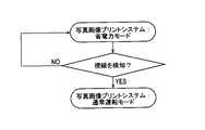
この場合、図3に示すように、電力供給制御部32は予め省電力モードをとっていて、第1表示パネル22a、プリンタ15、課金システム8および操作制御部31に対して電力を供給するが、第2表示パネル22bに対する電力供給を停止し、第2表示パネル22bが完全に暗くなっている(図9参照)。 In this case, as shown in FIG. 3, the power
そして操作者が写真画像プリントシステム10の前方に立つことにより、視線センサ27により操作者の視線が検知され、視線センサ27からの信号に基づいて、電力供給制御部32は通常運転モードをとる。このとき、第1表示パネル22a、プリンタ15、課金システム8および操作制御部31に対して引き続いて電力を供給するとともに、第2表示パネル22bに対しても電力が供給されて、第2表示パネルは明るくなる。 Then, when the operator stands in front of the photographic
次に操作者は、第2表示パネル22bの画面に対して必要な操作を行う。この間、画像情報が格納されたSDカード、CD-ROM等のデジタルメディアを、PC本体21に設けられたデジタルメディア挿入口21a内に挿入するとともに、コイン投入口18aまたはお札投入口18bから必要な料金を支払う。 Next, the operator performs necessary operations on the screen of the
このように操作者が第2表示パネル22bに対して必要な操作を行い、デジタルメディアをデジタルメディア挿入口21a内に挿入し、かつ必要な料金を支払うことにより、PC20の操作制御部31が作動してプリンタ15,15を駆動制御する。このことによりプリンタ15,15によりプリントされた写真画像印刷物が得られ、この写真画像印刷物は前面扉12に設けられた排出部の下端部にある集積部内に集積される。 In this way, the operator performs the necessary operations on the
操作者は次に前面扉12に設けられた透明な開閉扉12aを開くことにより、集積部内に集積された写真画像印刷物を取り出すことができる。その後、PC本体21からレシート口を介してレシートが排出される。 The operator can then take out the photographic image printed matter accumulated in the accumulating portion by opening the transparent opening /
その後に操作者が写真画像プリントシステム10から離れる。この場合、まず操作者が筐体11から視線を外すと、視線センサ27が視線を検知しなくなる。電力供給制御部32は、視線センサ27からの信号に基づいて、視線を検知しないと判断して省電力モードをとって第2表示パネル22bに対する電力の供給を停止して、第2表示パネル22bを完全に暗くする。この間、第1表示パネル22a、プリンタ15、課金システム8および操作制御部31に対しては引き続いて電力を供給する。 After that, the operator leaves the photographic
このように本実施の形態によれば、視線センサ27からの信号に基づいて、電力供給制御部32は通常運転モードをとって第2表示パネル22bに対する電力を供給し、あるいは省電力モードをとって第2表示パネル22bに対する電力供給を停止する。 As described above, according to the present embodiment, the power
このため通行人が写真画像プリントシステムに接近しただけで通常運転モードをとって各構成部材に電力を供給する場合に比べて、確実に省電力を図ることができる。 Therefore, it is possible to surely save power as compared with the case where the passerby takes the normal operation mode and supplies power to each component only by approaching the photographic image printing system.
<変形例>
次に図5および図6により、本発明の変形例について説明する。<Modification example>
Next, a modification of the present invention will be described with reference to FIGS. 5 and 6.
図5および図6に示す本発明の変形例は、電力供給制御部32の作用が異なるのみであり、他の構成は図1乃至図4に示す第1の実施の形態と略同一である。 The modified examples of the present invention shown in FIGS. 5 and 6 differ only in the operation of the power
まず操作者は、図5および図6に示すように、写真画像プリントシステム10の前方に立って写真画像プリントシステム10の操作を行う。 First, as shown in FIGS. 5 and 6, the operator stands in front of the photographic
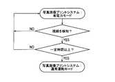
この場合、図5に示すように、電力供給制御部32は予め省電力モードをとっていて、第1表示パネル22a、プリンタ15、課金システム8および操作制御部31に対して電力を供給するが、第2表示パネル22bに対する電力供給を停止し、第2表示パネル22bが完全に暗くなっている(図9参照)。 In this case, as shown in FIG. 5, the power
そして操作者が写真画像プリントシステム10の前方に立つことにより、視線センサ27により操作者の視線が検知され、視線センサ27からの信号に基づいて、電力供給制御部32は視線検知の信号を所定時間(2~3秒間)以上連続して受信した後、通常運転モードをとる。このとき、第1表示パネル22a、プリンタ15、課金システム8および操作制御部31に対して引き続いて電力を供給するとともに、第2表示パネル22bに対しても電力が供給されて、第2表示パネルは明るくなる。 Then, when the operator stands in front of the photographic
その後に操作者が写真画像プリントシステム10に対して必要な操作を実行する。その後に操作者が写真画像プリントシステム10から離れる。この場合、図6に示すように、まず操作者が筐体11から視線を外すと、視線センサ27が視線を検知しなくなる。電力供給制御部32は、視線センサ27からの信号に基づいて、視線を検知しない信号が所定時間(2~3秒間)以上連続して続いた後、視線を検知しないと判断して省電力モードをとって第2表示パネル22bに対する電力の供給を停止して、第2表示パネル22bを完全に暗くする。この間、第1表示パネル22a、プリンタ15、課金システム8および操作制御部31に対しては引き続いて電力を供給する。 After that, the operator performs necessary operations on the photographic
このように本実施の形態によれば、視線センサ27からの信号に基づいて、電力供給制御部32は通常運転モードをとって第2表示パネル22bに対する電力を供給し、あるいは省電力モードをとって第2表示パネル22bに対する電力供給を停止する。 As described above, according to the present embodiment, the power
このため通行人が写真画像プリントシステムに接近しただけで通常運転モードをとって各構成部材に電力を供給する場合に比べて、確実に省電力を図ることができる。 Therefore, it is possible to surely save power as compared with the case where the passerby takes the normal operation mode and supplies power to each component only by approaching the photographic image printing system.
また電力供給制御部32は、視線センサ27からの信号が所定時間(2~3秒間)以上連続して続いた後に、通常運転モードまたは省電力モードをとるため、安定してかつ確実に通常運転モードおよび省電力モード間での切り換えを行うことができる。 Further, the power
<第2の実施の形態>
次に図7および図8により、本発明の第2の実施の形態について説明する。<Second embodiment>
Next, a second embodiment of the present invention will be described with reference to FIGS. 7 and 8.
図7および図8に示す本発明の第2の実施の形態は、電力供給制御部32の作用が異なるのみであり、他の構成は図1乃至図4に示す第1の実施の形態と略同一である。 The second embodiment of the present invention shown in FIGS. 7 and 8 differs only in the operation of the power
まず操作者は、写真画像プリントシステム10の前方に立って写真画像プリントシステム10の操作を行う。 First, the operator stands in front of the photographic
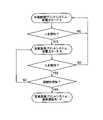
この場合、図7に示すように、電力供給制御部32は予め省電力モードAをとっていて、第1表示パネル22a、プリンタ15、課金システム8および操作制御部31に対して電力を供給するが、第2表示パネル22bに対する電力供給を停止し、第2表示パネル22bが完全に暗くなっている(図10参照)。 In this case, as shown in FIG. 7, the power
そして操作者が写真画像プリントシステム10の前方に立つことにより、視線センサ27により視線が検知され、かつ人感センサ28により人が検知され、視線センサ27と人感センサ28からの信号が電力供給制御部32へ送られる。この場合、電力供給制御部32はまず人感センサ28からの信号に基づいて、人を検知した場合に省電力モードBをとる。電力供給制御部32は、この省電力モードBをとることにより、第1表示パネル22a、プリンタ15、課金システム8および操作制御部31に対して電力を供給するとともに、第2表示パネル22bに対して部分的に電力供給を行って、第2表示パネル22bを若干明るくする(完全に明るくなっていない)。 Then, when the operator stands in front of the photographic
次に電力供給制御部32は視線センサ27からの信号に基づいて、視線を検知した後、通常運転モードをとる。 Next, the power
このとき電力供給制御部32は、第1表示パネル22a、プリンタ15、課金システム8および操作制御部31に対して引き続いて電力を供給するとともに、第2表示パネル22bに対しても完全に電力供給を行って、第2表示パネル22bを明るくする。 At this time, the power
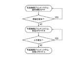
その後に操作者が写真画像プリントシステム10に対して必要な操作を実行する。その後、操作者が写真画像プリントシステム10から離れる。この場合、図8に示すように、まず操作者が筐体11から視線を外すと、視線センサ27が視線を検知しなくなる。電力供給制御部32は、視線センサ27からの信号に基づいて、視線を検知しないと判断して省電力モードBをとり、第2表示パネル22bに対して一部電力供給を行って、第2表示パネル22bを部分的に暗くする。次に電力供給制御部32は人感センサ28からの信号に基づいて、人を検知しないと判断して、省電力モードAをとり、第2表示パネル22bに対する電力供給を停止して、第2表示パネル22bを完全に暗くする。この間、第1表示パネル22a、プリンタ15、課金システム8および操作制御部31に対しては引き続いて電力を供給する。 After that, the operator performs necessary operations on the photographic
このように本実施の形態によれば、視線センサ27からの信号に基づいて、電力供給制御部32は通常運転モードをとって第2表示パネル22bに対する電力を供給し、あるいは省電力モードA,Bをとって第2表示パネル22bに対する電力供給を部分的に行ったり完全に停止する。 As described above, according to the present embodiment, the power
このため通行人が写真画像プリントシステムに接近しただけで通常運転モードをとって各構成部材に電力を供給する場合に比べて、確実に省電力を図ることができる。 Therefore, it is possible to surely save power as compared with the case where the passerby takes the normal operation mode and supplies power to each component only by approaching the photographic image printing system.
また電力供給制御部32は、視線センサ27と人感センサ28からの信号に基づいて、通常運転モード、省電力モードAあるいは省電力モードBをとって、第2表示パネル22bに対する電力供給を調整するので、実情に沿ってきめ細かく省電力制御を実行することができる。 Further, the power
6a プリンタ収納領域
6b 課金システム収納領域
8 課金システム
10 写真画像プリントシステム
11 筐体
11a 天板
11b 側方側板
12 前面扉
12a 開閉扉
15 プリンタ
20 PC
21 PC本体
21a デジタルメディア挿入口
22 表示パネル
22a 第1表示パネル
22b 第2表示パネル
27 視線センサ
28 人感センサ
31 操作制御部
31A 画像データ読込書込手段
31B 画像編集合成手段
32 電力供給制御部6a
21 PC
Claims (3)
Translated fromJapanese前記筐体に設けられた表示パネルと、
前記筐体に設けられたプリンタと、
前記筐体に設けられ、視線を検知する視線センサと、
前記筐体に配置され、前記表示パネルによって入力された操作信号に基づいて前記プリンタにより写真画像印刷物を作成する操作制御部と、
前記表示パネルおよび前記プリンタへの電力供給を制御する電力供給制御部とを備え、 前記電力供給制御部は、通常運転モードをとって、前記表示パネルおよび前記プリンタへの電力を供給し、省電力モードをとって少なくとも前記表示パネルへの電力供給を制限し、
前記筐体に人を検知する人感センサが設けられ、
前記電力供給制御部は、前記人感センサおよび前記視線センサからの信号に基づいて、人を検知しかつ視線を検知した場合に前記通常運転モードをとり、
前記電力供給制御部の前記省電力モードは、前記表示パネルへの電力供給を停止する省電力モードAと前記表示パネルへ一部電力供給を行う省電力モードBとからなり、
前記電力供給制御部は、前記人感センサおよび前記視線センサからの信号に基づいて、前記省電力モードAの状態で人を検知した場合に、前記省電力モードBをとり、その後に視線を検知した場合に前記通常運転モードをとり、前記通常運転モードの状態で視線を検知しない場合に前記省電力モードBをとり、その後に人を検知しない場合に前記省電力モードAをとる、写真画像プリントシステム。With the housing
Thedisplay panel provided in the housing and
The printer provided in the housing and
A line-of-sight sensor provided in the housing to detect the line of sight,
An operation control unit arranged in the housing and creating a photographic image printed matter by the printer based on an operation signal input by the display panel.
The display panel and the power supply control unit for controlling the power supply to the printer are provided, and the power supply control unit takes anormal operation mode to supply power to the display panel and the printer tosave power. Take power mode to at least limit the power supply to the display panel,
A motion sensor for detecting a person is provided in the housing, and a motion sensor is provided.
The power supply control unit takes the normal operation mode when it detects a person and detects the line of sight based on the signals from the motion sensor and the line-of-sight sensor.
The power saving mode of the power supply control unit includes a power saving mode A for stopping the power supply to the display panel and a power saving mode B for partially supplying power to the display panel.
When the power supply control unit detects a person in the state of the power saving mode A based on the signals from the human sensor and the line of sight sensor, the power supply control unit takes the power saving mode B and then detects the line of sight. If this is the case, the normal operation mode is taken, the power saving mode B is taken when the line of sight is not detected in the normal operation mode, and then the power saving mode A is taken when no person is detected. Photo image printing system.
Priority Applications (1)
| Application Number | Priority Date | Filing Date | Title |
|---|---|---|---|
| JP2018042313AJP7064711B2 (en) | 2018-03-08 | 2018-03-08 | Photo image printing system |
Applications Claiming Priority (1)
| Application Number | Priority Date | Filing Date | Title |
|---|---|---|---|
| JP2018042313AJP7064711B2 (en) | 2018-03-08 | 2018-03-08 | Photo image printing system |
Publications (2)
| Publication Number | Publication Date |
|---|---|
| JP2019155643A JP2019155643A (en) | 2019-09-19 |
| JP7064711B2true JP7064711B2 (en) | 2022-05-11 |
Family
ID=67994408
Family Applications (1)
| Application Number | Title | Priority Date | Filing Date |
|---|---|---|---|
| JP2018042313AActiveJP7064711B2 (en) | 2018-03-08 | 2018-03-08 | Photo image printing system |
Country Status (1)
| Country | Link |
|---|---|
| JP (1) | JP7064711B2 (en) |
Families Citing this family (1)
| Publication number | Priority date | Publication date | Assignee | Title |
|---|---|---|---|---|
| JP2023124290A (en)* | 2022-02-25 | 2023-09-06 | 沖電気工業株式会社 | Information processing apparatus, information processing method, and program |
Citations (6)
| Publication number | Priority date | Publication date | Assignee | Title |
|---|---|---|---|---|
| JP2004280461A (en) | 2003-03-14 | 2004-10-07 | Kyocera Mita Corp | Print managing device and wide area printing device |
| JP2011123763A (en) | 2009-12-11 | 2011-06-23 | Lenovo Singapore Pte Ltd | Power control device, power control method, and computer-executable program |
| JP2013168764A (en) | 2012-02-15 | 2013-08-29 | Sharp Corp | Image formation system |
| US20140208145A1 (en) | 2012-03-25 | 2014-07-24 | Jose Piccolotto | Methods and apparatus for saving power |
| JP2016178348A (en) | 2015-03-18 | 2016-10-06 | キヤノン株式会社 | Information processing device, control method therefor and program |
| JP2017175525A (en) | 2016-03-25 | 2017-09-28 | 富士ゼロックス株式会社 | Information processing device and image processing device |
Family Cites Families (1)
| Publication number | Priority date | Publication date | Assignee | Title |
|---|---|---|---|---|
| JPH11288259A (en)* | 1998-02-06 | 1999-10-19 | Sanyo Electric Co Ltd | Method and device for power saving control |
- 2018
- 2018-03-08JPJP2018042313Apatent/JP7064711B2/enactiveActive
Patent Citations (6)
| Publication number | Priority date | Publication date | Assignee | Title |
|---|---|---|---|---|
| JP2004280461A (en) | 2003-03-14 | 2004-10-07 | Kyocera Mita Corp | Print managing device and wide area printing device |
| JP2011123763A (en) | 2009-12-11 | 2011-06-23 | Lenovo Singapore Pte Ltd | Power control device, power control method, and computer-executable program |
| JP2013168764A (en) | 2012-02-15 | 2013-08-29 | Sharp Corp | Image formation system |
| US20140208145A1 (en) | 2012-03-25 | 2014-07-24 | Jose Piccolotto | Methods and apparatus for saving power |
| JP2016178348A (en) | 2015-03-18 | 2016-10-06 | キヤノン株式会社 | Information processing device, control method therefor and program |
| JP2017175525A (en) | 2016-03-25 | 2017-09-28 | 富士ゼロックス株式会社 | Information processing device and image processing device |
Also Published As
| Publication number | Publication date |
|---|---|
| JP2019155643A (en) | 2019-09-19 |
Similar Documents
| Publication | Publication Date | Title |
|---|---|---|
| JP7064711B2 (en) | Photo image printing system | |
| US20020003963A1 (en) | Image printing apparatus | |
| JP2008040746A (en) | Self-photo printing device | |
| CN103223790B (en) | The control method of tape deck, control device, tape deck and recording medium | |
| US8928925B2 (en) | Multifunction device and method for printing and reading data on a medium | |
| JP2005119083A (en) | Image output apparatus, image display method, program, and recording medium | |
| CN201796430U (en) | Self-service digital photo, lottery ticket printing and lottery sales all-in-one machine | |
| JP4647198B2 (en) | Image output device | |
| JP2006060662A (en) | Image output apparatus, program, and recording medium | |
| JP2000195226A (en) | Data printing/cd-r writing machine for digital camera | |
| JP2006163675A (en) | Image output apparatus, program, and recording medium | |
| JP4459796B2 (en) | Image output apparatus, program, and recording medium | |
| JP7010026B2 (en) | Printer and printer control method | |
| JP4556462B2 (en) | PHOTOGRAPHIC PRINTING DEVICE, PHOTOGRAPHIC PRINTING DEVICE CONTROL PROGRAM, COMPUTER-READABLE RECORDING MEDIUM, AND PHOTOGRAPHIC PRINTING DEVICE CONTROL METHOD | |
| RU38236U1 (en) | PHOTO AUTOMATIC | |
| JP2006272617A (en) | Image output device | |
| JP2004188772A (en) | Printing system | |
| JP2006101098A (en) | Image forming apparatus | |
| JP2002292961A (en) | Printing system and printing device | |
| JP2005186314A (en) | Image output device | |
| JP6183690B2 (en) | Photographic image printing system | |
| JPH08156364A (en) | Bankbook printer and bankbook printing method | |
| JP2014222417A (en) | Photographic image print system | |
| JP2005149251A (en) | Image output device | |
| JP2011035653A (en) | Photograph processing system, and photograph processing method |
Legal Events
| Date | Code | Title | Description |
|---|---|---|---|
| A621 | Written request for application examination | Free format text:JAPANESE INTERMEDIATE CODE: A621 Effective date:20210126 | |
| A977 | Report on retrieval | Free format text:JAPANESE INTERMEDIATE CODE: A971007 Effective date:20211227 | |
| A131 | Notification of reasons for refusal | Free format text:JAPANESE INTERMEDIATE CODE: A131 Effective date:20220107 | |
| A521 | Request for written amendment filed | Free format text:JAPANESE INTERMEDIATE CODE: A523 Effective date:20220301 | |
| TRDD | Decision of grant or rejection written | ||
| A01 | Written decision to grant a patent or to grant a registration (utility model) | Free format text:JAPANESE INTERMEDIATE CODE: A01 Effective date:20220325 | |
| A61 | First payment of annual fees (during grant procedure) | Free format text:JAPANESE INTERMEDIATE CODE: A61 Effective date:20220407 | |
| R150 | Certificate of patent or registration of utility model | Ref document number:7064711 Country of ref document:JP Free format text:JAPANESE INTERMEDIATE CODE: R150 |