JP7064603B2 - Clinical analyzer and cuvette transfer method - Google Patents
Clinical analyzer and cuvette transfer methodDownload PDFInfo
- Publication number
- JP7064603B2 JP7064603B2JP2020544442AJP2020544442AJP7064603B2JP 7064603 B2JP7064603 B2JP 7064603B2JP 2020544442 AJP2020544442 AJP 2020544442AJP 2020544442 AJP2020544442 AJP 2020544442AJP 7064603 B2JP7064603 B2JP 7064603B2
- Authority
- JP
- Japan
- Prior art keywords
- cuvette
- gate
- cam
- chute
- plunger
- Prior art date
- Legal status (The legal status is an assumption and is not a legal conclusion. Google has not performed a legal analysis and makes no representation as to the accuracy of the status listed.)
- Active
Links
- 238000000034methodMethods0.000titleclaimsdescription24
- 238000011534incubationMethods0.000claimsdescription31
- 230000004044responseEffects0.000claimsdescription12
- 230000008569processEffects0.000claimsdescription7
- 230000000903blocking effectEffects0.000claimsdescription3
- 230000007246mechanismEffects0.000description10
- 230000003287optical effectEffects0.000description6
- 239000007788liquidSubstances0.000description4
- 230000008859changeEffects0.000description2
- 238000000429assemblyMethods0.000description1
- 230000000712assemblyEffects0.000description1
- 230000000739chaotic effectEffects0.000description1
- 239000003153chemical reaction reagentSubstances0.000description1
- 230000005484gravityEffects0.000description1
- 238000003780insertionMethods0.000description1
- 230000037431insertionEffects0.000description1
- 239000000463materialSubstances0.000description1
- 238000012986modificationMethods0.000description1
- 230000004048modificationEffects0.000description1
- 239000011541reaction mixtureSubstances0.000description1
- 230000003068static effectEffects0.000description1
Images


Classifications
- B—PERFORMING OPERATIONS; TRANSPORTING
- B65—CONVEYING; PACKING; STORING; HANDLING THIN OR FILAMENTARY MATERIAL
- B65G—TRANSPORT OR STORAGE DEVICES, e.g. CONVEYORS FOR LOADING OR TIPPING, SHOP CONVEYOR SYSTEMS OR PNEUMATIC TUBE CONVEYORS
- B65G47/00—Article or material-handling devices associated with conveyors; Methods employing such devices
- B65G47/74—Feeding, transfer, or discharging devices of particular kinds or types
- B65G47/88—Separating or stopping elements, e.g. fingers
- B65G47/8876—Separating or stopping elements, e.g. fingers with at least two stops acting as gates
- B65G47/8884—Stops acting asynchronously, e.g. one stop open, next one closed or the opposite
- G—PHYSICS
- G01—MEASURING; TESTING
- G01N—INVESTIGATING OR ANALYSING MATERIALS BY DETERMINING THEIR CHEMICAL OR PHYSICAL PROPERTIES
- G01N35/00—Automatic analysis not limited to methods or materials provided for in any single one of groups G01N1/00 - G01N33/00; Handling materials therefor
- G01N35/02—Automatic analysis not limited to methods or materials provided for in any single one of groups G01N1/00 - G01N33/00; Handling materials therefor using a plurality of sample containers moved by a conveyor system past one or more treatment or analysis stations
- G01N35/04—Details of the conveyor system
- B—PERFORMING OPERATIONS; TRANSPORTING
- B65—CONVEYING; PACKING; STORING; HANDLING THIN OR FILAMENTARY MATERIAL
- B65G—TRANSPORT OR STORAGE DEVICES, e.g. CONVEYORS FOR LOADING OR TIPPING, SHOP CONVEYOR SYSTEMS OR PNEUMATIC TUBE CONVEYORS
- B65G2201/00—Indexing codes relating to handling devices, e.g. conveyors, characterised by the type of product or load being conveyed or handled
- B65G2201/02—Articles
- B65G2201/0235—Containers
- B65G2201/0244—Bottles
- G—PHYSICS
- G01—MEASURING; TESTING
- G01N—INVESTIGATING OR ANALYSING MATERIALS BY DETERMINING THEIR CHEMICAL OR PHYSICAL PROPERTIES
- G01N35/00—Automatic analysis not limited to methods or materials provided for in any single one of groups G01N1/00 - G01N33/00; Handling materials therefor
- G01N35/02—Automatic analysis not limited to methods or materials provided for in any single one of groups G01N1/00 - G01N33/00; Handling materials therefor using a plurality of sample containers moved by a conveyor system past one or more treatment or analysis stations
- G01N35/04—Details of the conveyor system
- G01N2035/0401—Sample carriers, cuvettes or reaction vessels
- G01N2035/0412—Block or rack elements with a single row of samples
- G—PHYSICS
- G01—MEASURING; TESTING
- G01N—INVESTIGATING OR ANALYSING MATERIALS BY DETERMINING THEIR CHEMICAL OR PHYSICAL PROPERTIES
- G01N35/00—Automatic analysis not limited to methods or materials provided for in any single one of groups G01N1/00 - G01N33/00; Handling materials therefor
- G01N35/02—Automatic analysis not limited to methods or materials provided for in any single one of groups G01N1/00 - G01N33/00; Handling materials therefor using a plurality of sample containers moved by a conveyor system past one or more treatment or analysis stations
- G01N35/04—Details of the conveyor system
- G01N2035/0439—Rotary sample carriers, i.e. carousels
- G01N2035/0444—Rotary sample carriers, i.e. carousels for cuvettes or reaction vessels
- G—PHYSICS
- G01—MEASURING; TESTING
- G01N—INVESTIGATING OR ANALYSING MATERIALS BY DETERMINING THEIR CHEMICAL OR PHYSICAL PROPERTIES
- G01N35/00—Automatic analysis not limited to methods or materials provided for in any single one of groups G01N1/00 - G01N33/00; Handling materials therefor
- G01N35/02—Automatic analysis not limited to methods or materials provided for in any single one of groups G01N1/00 - G01N33/00; Handling materials therefor using a plurality of sample containers moved by a conveyor system past one or more treatment or analysis stations
- G01N35/04—Details of the conveyor system
- G01N2035/046—General conveyor features
- G01N2035/0465—Loading or unloading the conveyor
- G—PHYSICS
- G01—MEASURING; TESTING
- G01N—INVESTIGATING OR ANALYSING MATERIALS BY DETERMINING THEIR CHEMICAL OR PHYSICAL PROPERTIES
- G01N35/00—Automatic analysis not limited to methods or materials provided for in any single one of groups G01N1/00 - G01N33/00; Handling materials therefor
- G01N35/02—Automatic analysis not limited to methods or materials provided for in any single one of groups G01N1/00 - G01N33/00; Handling materials therefor using a plurality of sample containers moved by a conveyor system past one or more treatment or analysis stations
- G01N35/04—Details of the conveyor system
- G01N2035/0496—Other details
Landscapes
- General Health & Medical Sciences (AREA)
- Physics & Mathematics (AREA)
- Life Sciences & Earth Sciences (AREA)
- Chemical & Material Sciences (AREA)
- Analytical Chemistry (AREA)
- Biochemistry (AREA)
- Immunology (AREA)
- General Physics & Mathematics (AREA)
- Health & Medical Sciences (AREA)
- Pathology (AREA)
- Engineering & Computer Science (AREA)
- Mechanical Engineering (AREA)
- Automatic Analysis And Handling Materials Therefor (AREA)
- Apparatus Associated With Microorganisms And Enzymes (AREA)
Description
Translated fromJapanese関連出願の相互参照
本出願は、参照によってその内容全体を本明細書に組み入れる2018年2月23日出願の米国仮特許出願第62/634,334号の優先権を主張する。Cross-reference to related applications This application claims the priority of US Provisional Patent Application No. 62 / 634,334 filed February 23, 2018, which is incorporated herein by reference in its entirety.
本開示は、キュベットを使用する臨床分析装置に関し、より詳細には、キュベットを臨床分析装置内で移送するデバイスおよび方法に関する。 The present disclosure relates to clinical analyzers using cuvettes, and more particularly to devices and methods of transporting cuvettes within clinical analyzers.
臨床分析装置は、反応の実施および/または液体の移送に個別のキュベットを使用することができる。キュベットは、キュベットホッパに装填され、次いで、キュベットホッパから取り出されて臨床分析装置内の他の場所に移送される。キュベットを移送前に単体化しないと、キュベットが一団になり、移送システムを詰まらせることがある。 The clinical analyzer can use a separate cuvette to carry out the reaction and / or transfer the liquid. The cuvette is loaded into the cuvette hopper and then removed from the cuvette hopper and transferred elsewhere in the clinical analyzer. If the cuvettes are not united before transfer, the cuvettes may come together and clog the transfer system.
一態様では、臨床分析装置が提供される。臨床分析装置は、第1の場所と;第2の場所と;第1の場所と第2の場所との間に延び、キュベットが第1の場所から第2の場所まで摺動することを可能にするように構成された、シュートと;キュベットがシュートに沿って摺動することが可能にされる第1の位置と、キュベットがシュートに沿って摺動することが阻止される第2の位置との間で可動である1つまたはそれ以上のゲートを含む、装填アセンブリとを含む。 In one aspect, a clinical analyzer is provided. The clinical analyzer extends between the first location and; the second location; the first location and the second location, allowing the cuvette to slide from the first location to the second location. With a chute configured to; a first position where the cuvette is allowed to slide along the chute and a second position where the cuvette is prevented from sliding along the chute. Includes a loading assembly, including one or more gates that are movable to and from.
別の態様では、臨床分析装置が提供される。臨床分析装置は、複数のキュベットを受けるように構成されたキュベットホッパと;キュベットを受けるように構成された1つまたはそれ以上のレセプタクルを有するインキュベーションリングと、キュベットホッパに近接する第1の場所とインキュベーションリングに近接する第2の場所との間に延び、キュベットが第1の場所から第2の場所へ摺動することを可能にするように構成された、シュートと;キュベットがシュートに沿って摺動することが可能にされる第1の位置とキュベットがシュートに沿って摺動することが阻止される第2の位置との間で可動である第1のゲートと、キュベットがシュートに沿って摺動することが可能にされる第1の位置とキュベットがシュートに沿って摺動することが阻止される第2の位置との間で可動である第2のゲートと、第1のゲートと第2のゲートとの間にあり1つのキュベットを受容可能な空間とを含む、装填アセンブリとを含む。 In another aspect, a clinical analyzer is provided. The clinical analyzer is a cuvette hopper configured to receive multiple cuvettes; an incubation ring with one or more receptacles configured to receive cuvettes, and a first location close to the cuvette hopper. With a chute that extends between a second location close to the incubation ring and is configured to allow the cuvette to slide from the first location to the second location; the cuvette is along the chute. A first gate that is movable between a first position that allows sliding and a second position that prevents the cuvette from sliding along the chute, and a cuvette along the chute. A second gate that is movable between a first position that allows the cuvette to slide and a second position that prevents the cuvette from sliding along the chute, and a first gate. Includes a loading assembly, including a space between and a second gate that can accommodate one cuvette.
別の態様では、キュベットを臨床分析装置内で移送する方法が提供され、方法は、1つまたはそれ以上のキュベットをシュートに装填する工程であって、1つまたはそれ以上のキュベットはシュートに沿って第1のゲートへ摺動する、工程と;第1のゲートを用いて、シュートに沿った1つまたはそれ以上のキュベットの摺動の動きを阻止する工程と;第1のゲートから、1つのキュベットを受容可能な距離を置いて配置された第2のゲートを用いて、キュベットの動きを阻止する工程と;第1のキュベットが第2のゲートへ摺動することを可能にするように第1のゲートを後退させる工程と;第1のゲートを通過してキュベットが動くことを防止するために、第1のゲートを延ばす工程と;第1のキュベットがシュートに沿って摺動することを可能にするように第2のゲートを後退させる工程とを含む。 In another aspect, a method of transferring a cuvette within a clinical analyzer is provided, the method of loading one or more cuvettes into a chute, one or more cuvettes along the chute. And sliding to the first gate; using the first gate to prevent the sliding movement of one or more cuvettes along the chute; from the first gate to 1 A step of blocking the movement of the cuvette using a second gate located at an acceptable distance between the two cuvettes; allowing the first cuvette to slide to the second gate. The step of retracting the first gate; the step of extending the first gate to prevent the cuvette from moving through the first gate; the first cuvette sliding along the chute. Includes a step of retracting the second gate to enable.
数多くの他の態様は、この開示の上記その他の実施形態に従って提供される。この開示の実施形態の他の構成および態様は、以下にある詳細な説明、添付の特許請求の範囲および添付の図面からより十分に明らかになろう。 Numerous other aspects are provided in accordance with the other embodiments described above in this disclosure. Other configurations and embodiments of this disclosure embodiment will be more fully apparent from the detailed description below, the appended claims and the accompanying drawings.
以下に述べる図面は、例示を目的としており、必ずしも縮尺通りに描かれていない。図面は、いかなる形においても、本開示の範囲の限定を意図するものではない。 The drawings described below are for illustration purposes only and are not necessarily drawn to scale. The drawings are not intended to limit the scope of this disclosure in any way.
次に、添付の図面に示される本開示の例示的な実施形態を詳細に参照する。図面全体を通じて、可能な限り、いくつかの図面を通して同じまたは同等の要素を示すのに同じ参照符号を使用する。本明細書に記載される様々な実施形態の構成は、特段の記載がない限り、互いに組み合わせることができる。 The exemplary embodiments of the present disclosure set forth in the accompanying drawings will then be referred to in detail. Use the same reference code to indicate the same or equivalent elements throughout the drawing, wherever possible, throughout the drawing. The configurations of the various embodiments described herein can be combined with each other unless otherwise stated.
臨床分析装置は、液体の混合および/または移送に個別のキュベットを使用することができる。これらの臨床分析装置は、無秩序の向きのキュベットが充填されたキュベットホッパを含む。臨床分析装置内の機構は、キュベットをキュベットホッパから取り出し、それらを臨床分析装置内の他の場所に送達する。いくつかの実施形態では、機構は、キュベットをキュベットホッパからインキュベーションリングに移送し、そこでキュベットは、一度に1つ特定の向きでレセプタクルに装填される。キュベットの装填が一度に1つでないと、キュベットが臨床分析装置内の移送機構でつかえてそれを詰まらせることがある。 The clinical analyzer can use individual cuvettes for liquid mixing and / or transfer. These clinical analyzers include a cuvette hopper filled with cuvettes in a chaotic orientation. The mechanism within the clinical analyzer removes the cuvettes from the cuvette hopper and delivers them elsewhere within the clinical analyzer. In some embodiments, the mechanism transfers the cuvette from the cuvette hopper to the incubation ring, where the cuvette is loaded into the receptacle one at a time in a particular orientation. If the cuvette is not loaded one at a time, the cuvette may get stuck in the transfer mechanism within the clinical analyzer and clog it.
本明細書に開示される臨床分析装置は、キュベットホッパとインキュベーションリングとの間のような、第1の場所と第2の場所との間に延びる少なくとも1つのシュートを含む。シュートに対して可動なゲートは、一度に1つのキュベットがゲートを通過できるようにする、キュベットのためのステージング(staging)域を作成することができる。概ねキュベットのサイズの空間は、第1のゲートと第2のゲートを分離することができる。動作中、両方のゲートは、キュベットがシュート上を動かないように延ばされる。第1のゲートは、第1のキュベットが第1のゲートと第2のゲートとの間の空間に入ることを可能にするように、開くまたは後退することができる。次いで、第1のゲートは、第1のキュベットを単体化または単離するように閉じることができる。次いで、第2のゲートが、第1のキュベットがシュートに沿って動くことを可能にするように、後退することができる。いくつかの実施形態では、第1のキュベットは、摺動してシュートから出てインキュベーションリングのレセプタクルに入ることができる。したがって、一度に1つのキュベットがシュート上をインキュベーションリングへ動くことができ、したがって上述した詰まりが防止される。 The clinical analyzer disclosed herein includes at least one shoot extending between a first location and a second location, such as between a cuvette hopper and an incubation ring. A gate movable against the chute can create a staging area for the cuvette that allows one cuvette to pass through the gate at a time. A space approximately the size of a cuvette can separate the first and second gates. During operation, both gates are extended to prevent the cuvette from moving over the chute. The first gate can be opened or retracted to allow the first cuvette to enter the space between the first gate and the second gate. The first gate can then be closed to unify or isolate the first cuvette. The second gate can then be retracted to allow the first cuvette to move along the chute. In some embodiments, the first cuvette can slide out of the chute and into the receptacle of the incubation ring. Thus, one cuvette can move over the chute to the incubation ring at a time, thus preventing the above-mentioned clogging.
臨床分析装置のいくつかの実施形態は、第1のゲートと第2のゲートに対して可動なカムを含む。カムの動きによって、第1のゲートと第2のゲートは、シュートへと延ばされ、それから後退させられる。臨床分析装置のいくつかの実施形態は、上述のカムを動作させる単一の駆動機構を含み、それによって臨床分析装置は費用が削減され、簡素化される。 Some embodiments of the clinical analyzer include a first gate and a cam that is movable relative to the second gate. The movement of the cam causes the first and second gates to extend to the chute and then retract. Some embodiments of the clinical analyzer include a single drive mechanism for operating the cams described above, whereby the clinical analyzer is cost-reduced and simplified.
臨床分析装置のいくつかの実施形態は、インキュベーションリングのレセプタクルのような場所にキュベットを着座させるプランジャを含む。プランジャは、プランジャがキュベットに接触したか、および/またはそれを着座させたかを決定するために、圧力を感知するセンサを含むことができる。プランジャは、キュベットの頂部部分に接触する、またはキュベット内へと延びることができる。プランジャは、カムと一緒に動いてもよく、またはカムと一緒には動かなくてもよい。 Some embodiments of the clinical analyzer include a plunger that seats the cuvette in a place such as a receptacle in an incubation ring. The plunger may include a pressure sensing sensor to determine if the plunger has touched and / or seated the cuvette. The plunger can touch the top of the cuvette or extend into the cuvette. The plunger may or may not move with the cam.
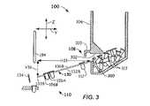
図1~図10を参照して、本明細書においてキュベット装填アセンブリを含む臨床分析装置およびキュベットを移送する方法の例示的な実施形態のさらなる詳細を説明する。 With reference to FIGS. 1-10, further details of exemplary embodiments of clinical analyzers including cuvette loading assemblies and methods of transporting cuvettes are described herein.
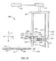
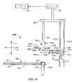
次に図1Aおよび図1Bを参照する。図1Aは、第1の状態にある臨床分析装置100の一部分の上面図であり、図1Bは、臨床分析装置100の部分的な側面断面図である。図1Aの臨床分析装置100の図は、インキュベーションリング102、キュベットホッパ106、フィーダ108、およびキュベット装填アセンブリ110を含む。図面には、いくつかのキュベット112が臨床分析装置100の異なる場所に示されている。 Next, reference is made to FIGS. 1A and 1B. FIG. 1A is a top view of a part of the
インキュベーションリング102は、軸または中心点116周りに回転可能な円形デバイスとすることができる。インキュベーションリング102は、上面118と、下面120(図1B)と、上面118と下面120との間に延びる複数のレセプタクル122とを有することができる。各レセプタクル122は、キュベット112を受けるように構成される。たとえば、キュベット装填アセンブリ110は、インキュベーションリング102が中心点116周りに回転するときにキュベット112をインキュベーションリング102の個々のレセプタクル122に一度に1つ装填することができる。図1Aおよび図1Bに示される臨床分析装置100は、キュベット112Aがステージング場所にありインキュベーションリング102のレセプタクル122Aに受け入れられるように設定される、第1の状態にある。 The
さらに、キュベット112の等角図、側面図、正面図および上面図をそれぞれ示す図2A~図2Dを参照する。キュベット112は、図2A~図2Dに示されるものとは異なる構成を有することもできる。キュベット112は、容器部分200と、リップ202とを含むことができる。容器部分200は、液体(たとえば、試薬または反応混合物)を保持するように構成される。容器部分200の断面形状は、広幅側面204Aと狭幅側面204Bを有する略矩形とすることができ、広幅側面204Aは、狭幅側面204Bより幅が広い。容器部分200は、互いに距離D21離れた上端206と下端208を含むことができる。距離D21は、約1.49インチ(3.77cm)とすることができる。容器部分200およびリップ202を含めたキュベット112の全長は、約1.5インチ(3.8cm)とすることができる。 Further, FIGS. 2A to 2D showing an isometric view, a side view, a front view and a top view of the
リップ202は、キュベット112の位置合わせおよび移送を可能にすることができる。たとえば、キュベット112は、その移送の間、リップ202で支持される。リップ202は、上面210と下面212を有することができる。リップ202は、上面210と下面212との間に約0.042インチ(1.02mm)の厚さD22(図2C)を有することができる。リップ202は、上面210と下面212との間、および容器部分200内へと延びる開口部216を含むことができる。開口部216は、液体の容器部分200への分配およびそこからの抜き取り(たとえば、吸引)を可能にする。 The
キュベット112は、リップ202の下面212と容器部分200の広幅側面204Aとの間に連結される1つまたはそれ以上の支持部材220を含むことができる。支持部材220の1つまたはそれ以上は、傾斜側部222を含むことができる。移送機構(図2A~図2Dには示されず)は、以下に記載するように、キュベット112の移送の間、傾斜側部222に接触することができる。傾斜側部は、シュート130に沿ったキュベット112の摺動性を促進することができ、キュベット112のための位置合わせ機構を提供することができる。 The
さらに、図1Aおよび図1Bを参照する。キュベットホッパ106は、複数のキュベット112を収納することができる。たとえば、使用者は、複数のキュベット112をキュベットホッパ106に装填することで、キュベットホッパ106を装填することができる。キュベット112は、キュベットホッパ106内にランダムに積み重ねられる、または配置される。フィーダ108は、キュベット112をキュベットホッパ106から取り出し、本明細書に記載されるようなキュベット装填アセンブリ110によって受けられるようにそれらを所定の向きに位置合わせすることができる。 Further refer to FIGS. 1A and 1B. The
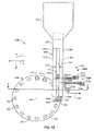
さらに、キュベットホッパ106、およびキュベット装填アセンブリ110に連結されたフィーダ108の断面図である図3を参照する。フィーダ108は、キュベット112を配向および/または分離(たとえば、単体化)するタンブラ、ホイール300または他のデバイスを含むことができる。ルーフ302または他のデバイスは、ホイール300の近くまたは上にあるキュベット112の数を減少させることによってホイール300に掛かる負荷を制限するように、ホイール300の上に配置することができる。したがって、ルーフ302は、ホイール300の近くでキュベット112がつかえることになる可能性を減少させる。ルーフ302は、さらに、キュベット112をフィーダ108へ誘導することができる。キュベットホッパ106内のキュベット112を単体化し配向することに他の機構を使用することもできる。 Further, reference is made to FIG. 3, which is a cross-sectional view of the
フィーダ108は、キュベット112をシュート130へと供給および/または配向することができ、キュベット112をシュート130へと供給および/または配向することに使用される案内部310または他のデバイスを含むことができる。さらに図1Aおよび図1Bを参照すると、シュート130は、第1のレール132Aと第2のレール132Bとを含むことができ、それらの間には空間132Cがある。空間132Cは、第1のレール132Aと第2のレール132Bとの間の距離D11とすることができ、キュベット112の容器部分200(図2)を受けるのに十分な幅とすることができる。たとえば、距離D11は、キュベット112の容器部分200の上端206近くの狭幅側面204Bの幅よりわずかに大きくてよい。空間132Cは、キュベット112のリップ202または傾斜側部222が第1のレール132Aと第2のレール132Bに接触することを可能にする。そのような接触によって、キュベット112は、本明細書に記載されるようにシュート130に沿って摺動することが可能になる。他の実施形態は、複数のシュートを含むことができる。たとえば、第1のシュートは、第1の方向に延び、第2の方向に延びる第2のシュートへキュベットを落下させることができる。 The
シュート130は、キュベット112がフィーダ108からシュート130に沿ってキュベット装填アセンブリ110へと摺動することを可能にするように、キュベット装填アセンブリ110に向かって傾斜していてよい。シュート130は、垂直距離V31下がり、水平距離H31に延び、スロープV31/H31を有することができる(図3)。スロープは、キュベット112がフィーダ108からキュベット装填アセンブリ110へと摺動することができるようにキュベット112とシュート130との間の摩擦力に打ち勝つのに十分な重力を提供することができる。 The
図1Bに示されるように、第1のレール132Aおよび第2のレール132Bは、空間132Cに向かって傾斜していてよい。傾斜面により、キュベット112は空間132Cの中心に向かって案内され、したがって位置合わせが改善される。傾斜面は、さらに、リップ202の下面212(図2C)の面積、または、支持部材220の、第1のレール132Aと第2のレール132Bに接触する表面(たとえば、側面222)の面積を減少させ、それによって、シュート130に沿ったキュベット112の摺動性が向上する。 As shown in FIG. 1B, the
第1のレール132Aは、上面136Aを有することができ、第2のレール132Bは、上面136Bを有することができる。上面136Aおよび上面136Bは、リップ202の下面212(図2B)に対して低い摩擦係数を有する材料とすることができる。低い摩擦係数によって、キュベット112は、シュート130に沿って摺動することが可能になる。リップ202の下面212ならびに上面136Aおよび上面136Bは、キュベット112がシュート130にあるゲートによって止められ、ゲートが除かれるとまた摺動に戻ることができるように、低静摩擦を有することができる。 The
第1のレール132Aは、端部133Aを有することができ、第2のレール132Bは、端部133Bを有することができる。ディフレクタ134は、端部133Aおよび端部133Bから距離D12のところに配置することができる。距離D12は、キュベット112の最大幅の長さより大きくてよい。たとえば、距離D12は、キュベット112のリップ202の最大幅部分より大きくてよい。キュベット112は、シュート130から出たときにディフレクタ134に接触することができ、ディフレクタ134との接触によってインキュベーションリング102のレセプタクル122内へと偏向またはその他の方法で案内される。 The
キュベット装填アセンブリ110は、キュベット112がインキュベーションリング102のレセプタクル122に挿入される前の、キュベット112のためのステージング域を提供することができる。図1Aの実施形態では、キュベット112Aは、ステージング域にある。キュベット装填アセンブリ110は、第1のゲートアセンブリ150Aと、第2のゲートアセンブリ150Bとを含むことができる。第1のゲートアセンブリ150Aは、第2のゲートアセンブリ150Bの鏡像であってよく、両方とも同じように動作することができる。第1のゲートアセンブリ150Aは、第1のゲート152Aを含むことができ、第2ゲートアセンブリ150Bは、第2のゲート152Bを含むことができる。第1のゲート152Aは、第1のナイフ部分156Aを含むことができ、第2のゲート152Bは、第2のナイフ部分156Bを含むことができる。第1のナイフ部分156Aは、傾斜部分157を含むことができる。傾斜部分157は、第1のゲート152Aが、隣り合うキュベット112間で動くことを可能にする。たとえば、傾斜部分157は、互いに接触していることがある隣り合うキュベット112間に第1のゲート152Aが入ることを可能にする先端または同様のものを有することができる。 The
図1Bおよび図3に示されるキュベット装填アセンブリ110の実施形態は、シュート130の下に配置された第1のゲート152Aおよび第2のゲート152Bを示している。他の実施形態では、第1のゲート152Aおよび第2のゲート152Bは、シュート130の上に配置することができる。図1Aに示される実施形態では、第1のゲート152Aは、第1のまたは後退位置にあり、第2のゲート152Bは、第2のまたは伸長位置にあり、これは臨床分析装置100の第1の状態と称することができる。本明細書に記載されるように、第1のゲート152Aおよび第2のゲート152Bの位置は、臨床分析装置100の動作とともに変わる。 The embodiment of the
支持体158(図1A)は、第1のゲート152Aおよび第2のゲート152Bに対して固定された場所にあってよい。第1のゲート152Aおよび第2のゲート152Bは、支持体158に対して可動であってよく、支持体158内のレセプタクル(図示せず)を通過することができる。第1のばね160Aは、支持体158と、第1のゲート152Aに固定された第1の部材162Aとの間に延びることができる。第2のばね160Bは、支持体158と、第2のゲート152Bに固定された第2の部材162Bとの間に延びることができる。第1のばね160Aおよび第2のばね160Bはそれぞれ、方向166に、第1のゲート152Aおよび第2のゲート152Bを付勢することができる。たとえば、第1のばね160Aおよび第2のばね160Bは、第1のゲート152Aおよび第2のゲート152Bを第1のまたは後退位置に付勢することができる。第1のゲート152Aおよび第2のゲート152Bを方向166に付勢することに他のデバイスを使用することもできる。 The support 158 (FIG. 1A) may be in a fixed location with respect to the
第1のカムフォロア170Aは、第1のゲート152Aに連結することができ、第2のカムフォロア170Bは、第2のゲート152Bに連結することができる。第1のカムフォロア170Aおよび第2のカムフォロア170Bはともに、第1のゲート152Aおよび第2のゲート152Bに対して回転するホイールをそれぞれ含むことができる。第1のカムフォロア170Aは、第1のカム172Aに接触することができ、第2のカムフォロア170Bは、第2のカム172Bに接触することができる。たとえば、第1のばね160Aは、第1のカム172Aに対して第1のカムフォロア170Aを付勢することができ、第2のばね160Bは、第2のカム172Bに対して第2のカムフォロア170Bを付勢することができる。いくつかの実施形態では、カムフォロアは、第1のカム172Aおよび第2のカム172Bに対して摺動する剛性部材とすることができる。 The
第1のカム172Aおよび第2のカム172Bは、Z方向に可動である可動カム支持体180(図1B)に連結することができる。たとえば、アクチュエータ181は、プロセッサ182から受けた命令に応じてZ方向にカム支持体180を動かすことができる。第1のカム172Aおよび第2のカム172Bはともに、カム支持体180の垂直(たとえば、Z方向)位置が第1のゲート152Aおよび第2のゲート152BのX方向の位置を決定するようなX方向の輪郭にすることができる。たとえば、カム支持体180がZ方向に動くと、第1のカムフォロア170Aおよび第2のカムフォロア170BはそれぞれX方向に第1のカム172Aおよび第2のカム172Bの輪郭に追従し、それによって第1のゲート152Aおよび第2のゲート152Bは、X方向に動かされる(たとえば、第1の位置と第2の位置との間で延び、および後退する)。本明細書に記載されるように、第1のゲート152Aおよび第2のゲート152BのX方向の動きによって、インキュベーションリング102へのキュベット112の装填が可能にされ、または防止される。 The
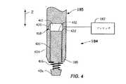
プランジャ184は、カム支持体180に連結することができる。プランジャ184は、レセプタクル122Aの上に位置する。プランジャ184は、インキュベーションリング102のレセプタクル122にキュベット112(たとえば、キュベット112A)を着座させ、またはその他の方法で配置してもよい。動作中、カム支持体180は、インキュベーションリング102に向かってZ方向に下方に可動である。この動きの間、プランジャ184は、キュベット112のリップ202の開口部216(図2A)に入り、キュベット112をレセプタクル122に押し込むことができる。したがって、そうではなく、プランジャ184は、不適当に着座されたキュベット112をインキュベーションリング102のレセプタクル122に着座させることもある。いくつかの実施形態では、プランジャ184の端部185は、テーパまたは斜面186(図1F)を有することができ、それによって位置合わせ不良のキュベット112の開口部216へのプランジャ184の挿入が改善される。 The
図4は、プランジャ184の端部185の一実施形態の断面図である。図4に示される端部185は、キュベット112(図1B)がインキュベーションリング102のレセプタクル122内に適切に着座されたかどうかを示すセンサ418を含む。端部185は、本体404と、本体404に対して可動である先端部406を含むことができる。先端部406は、本体404のキャビティ411内でZ方向に可動であるピストン410に連結する、またはそれと一体形成することができる。ピストン410は、本体404内に位置する上面412を含むことができる。ばね機構416は、ピストン410を本体404の外へZ方向に付勢することができる。機構(図示せず)は、ピストン410が本体404から延びることができる距離を制限することができる。 FIG. 4 is a cross-sectional view of an embodiment of the
本体404は、ピストン410の場所を示すセンサ418を含むことができる。たとえば、センサ418は、ピストン410が本体404内の所定の場所に達したことに応答して信号を生成することができる。図4に示されるセンサ418は、発光体420と、光検出器422を含み、それらの間の光路を含む。ピストン410が図4に示されるように延ばされると、光路は、発光体420と光検出器422との間に延びる。光検出器422への光の入射によって、光検出器422は、ピストン410がセンサ418より下にあることを示す信号を生成する。ピストン410が光路を遮断するように動くと、光検出器422によって生成される信号は、ピストン410がセンサ418のところまたはその上に位置することを示すように変わる。プロセッサ182は、光検出器422に電気接続していてよく、光検出器422によって生成される信号の変化を検出することができる。 The
上述したように、プランジャ184は、キュベット112(図2B)をインキュベーションリング102のレセプタクル122(たとえば、キュベット112Aをレセプタクル122A)内に着座させることができる。プランジャ184がキュベット112をレセプタクル122に押し込むとき、端部185は、キュベット112の下端208(図2B)に接触することができる。プランジャ184によって加えられる力は、ばね機構416によって加えられるばね力に打ち勝つことができ、それによってピストン410がキャビティ411内へと動かされ、発光体420と光検出器422との間の光路が遮断される。プロセッサ182は、光検出器422によって生成される信号の変化を、キュベット112がレセプタクル122内に適切に着座されたことの標示として解釈することができる。光路が遮断されたとき、プランジャ184によってZ方向に加えられる力が大きい場合、プロセッサ182は、キュベットが適切に着座されていないと決定することができる。光路が遮断されない、またはプランジャ184が力を及ぼすことができない場合、プロセッサ182は、キュベットがインキュベーションリング102のレセプタクル内に装填されていないと決定することができる。他のセンサを端部185に使用することもできる。たとえば、圧力センサは、キャビティ411内のピストン410の位置を示すことができる。 As mentioned above, the
再び図1Aおよび図1Bを参照すると、第1のカム172Aおよび第2のカム172Bは、第1のカムフォロア170Aおよび第2のカムフォロア170Bに対してZ方向のいくつかの位置を有することができる。臨床分析装置100は、第1のカム172Aおよび第2のカム172Bがそれぞれ第1のカムフォロア170Aおよび第2のカムフォロア170Bに接触する位置に応じて異なる状態にあると称される。図1Bに示される実施形態は、カム172A、172Bにおける3つの異なる位置である、第1の位置Z11、第2の位置Z12および第3の位置Z13を示している。第1の位置Z11がカムフォロア170A、170Bに接触するようにカム172A、172Bが配置されるとき、臨床分析装置100は、第1の状態にある。第2の位置Z12がカムフォロア170A、170Bに接触するようにカム172A、172Bが配置されるとき、臨床分析装置100は、第2の状態にある。第3の位置Z13がカムフォロア170A、170Bに接触するようにカム172A、172Bが配置されるとき、臨床分析装置100は、第3の状態にある。第1の状態では、図1Aおよび図1Bに示されるように、第1のゲート152Aは後退位置にあり、第2のゲート152Bは伸長位置にある。したがって、キュベット112Aは、第2のゲート152Bへ摺動することができ、そこで第2のゲート152Bによって止められる。具体的には、第1のゲート152Aは後退し、それによってキュベット112Aはシュート130に沿って第2のゲート152Bへ自由に摺動する。 With reference to FIGS. 1A and 1B again, the
カム支持体180がZ方向に下方に動くと、図1Cおよび図1Dに示されるように位置Z12に達し、臨床分析装置100は第2の状態になる。第2の状態では、第1のゲート152Aと第2のゲート152Bの両方が、図1Cおよび図1Dに示されるように延ばされ、それによってシュート130に沿ったキュベット112の摺動が阻止される。第2の状態では、キュベット112は、単一のキュベット112Aが第1のゲート152Aと第2のゲート152Bとの間に位置するように単体化される。他の実施形態では、1つまたはそれ以上のキュベット112が第1のゲート152Aと第2のゲート152Bとの間で受容可能であってもよい。 As the
カム支持体180がZ方向に下方に動き続けると、図1Eおよび図1Fに示されるように位置Z13に達し、臨床分析装置100は第3の状態になる。第3の状態では、第1のゲート152は延ばされ、第2のゲート152Bは後退される。この構成では、キュベット112Aは、第2のゲート152Bから解放されて下方に摺動し、シュート130を出てレセプタクル122A内へと落下する。キュベット112Aは、シュート130を離れた後、ディフレクタ134に接触する、または他の方法でディフレクタ134により案内され、レセプタクル122A内へと案内される。 As the
カム支持体180は、プランジャ184の端部185が図1Gに示されるようにキュベット112Aの底部に接触するポイントまで、Z方向に下方に移動し続けることができる。この構成は、臨床分析装置100の第4の状態と称することができる。プランジャ184がキュベット112Aの底部に接触したことをセンサ418(図4)が検出したときにプランジャ184がZ方向の特定の位置にあるかどうかを決定するように、プロセッサ182によってカム支持体180の位置が監視される。接触がZ方向の特定の位置の上でなされた場合、キュベット112Aがレセプタクル122A内に適切に着座されていないことを示す標示(たとえば、アラーム)が提供される。センサ418がキュベット112の底部を感知しなかった場合、レセプタクル122A内にキュベット112が配置されていないことを示す標示が提供される。 The
他の実施形態では、プランジャ184は、キュベット112A内に完全には延びない。そうではなく、先端部406(図4)は、キュベット112Aの開口部216(図2A)内へと部分的に延びることができるようにテーパ化してもよい。たとえば、先端部406の下側部分が開口部216より小さく、先端部406の上側部分が開口部216より大きくてもよい。この実施形態では、プランジャ184は、キュベット112Aが適切に着座されているかどうかを決定するのにキュベット112Aの全長D21(図2B)を動かなくてすむ。たとえば、先端部406がキュベット112Aの上面210に接触するはずの位置までプランジャ184が動き、センサ418がキュベット112Aを感知した場合、プロセッサ182は、キュベット112Aが適切に着座されていると決定することができる。センサ418が、Z方向の高すぎる位置でキュベット112Aを検出した場合、プロセッサ182は、キュベット112Aが適切に着座されていないと決定することができる。プランジャ184がキュベットに接触せずにZ方向に低すぎる位置まで動いた場合、プロセッサ182は、キュベット112Aがレセプタクル122A(図1D)にないことを示すことができる。いくつかの実施形態では、プランジャ184の少なくとも一部分は、レセプタクル122A内に進むまたは通ることができる。 In other embodiments, the
キュベット112Aがレセプタクル122A内に着座された後、カム支持体180は、Z方向に上昇することができる。プランジャ184がインキュベーションリング102から去った後、インキュベーションリング102は、別のキュベット112を受けるためにシュート130の端部の下に空のレセプタクル122を配置するように中心点116周りに回転することができる。 After the
位置Z12に達すると、第1のゲート152Aと第2のゲート152Bの両方が図1Cに示されるような伸長位置になるが、それらの間にキュベットは配置されない。カム支持体180がZ方向に上昇し続けると、位置Z11に達し、それによって第1のゲート152Aが後退し、図1Aに示されるように別のキュベット112が第2のゲート152B近くに配置される。次いで上述したプロセスが繰り返されて、キュベット112が単体化され、別のキュベットがインキュベーションリング102のレセプタクル122内に装填される。 Upon reaching position Z12, both the
上述したプロセスは、第1のゲート152Aおよび第2のゲート152Bを動かすために、第1のカムフォロア170Aおよび第2のカムフォロア170Bに接触する第1のカム172Aおよび第2のカム172Bを含む。アクチュエータのような他のデバイスを実装し、第1のゲート152Aおよび第2のゲート152Bを動かすこともできる。 The process described above includes a
臨床分析装置100および装填アセンブリ110は、キュベットをインキュベーションリング102に装填するとして述べてきた。他の実施形態では、装填装置は、キュベットを臨床分析装置100内またはそれに連結された他の場所に装填することもできる。それに応じて、プランジャ184は、これらの他の場所にキュベットを着座させ、キュベットの適切な配置を決定することができる。 The
別の態様では、図5の流れ図500によって、キュベットを臨床分析装置内で移送する方法が提供され説明される。方法は、502で、1つまたはそれ以上のキュベット(たとえば、キュベット112)をシュート(たとえば、シュート130)に装填することを含み、1つまたはそれ以上のキュベットは、シュートに沿って第1のゲート(たとえば、第1のゲート152A)へ摺動する。方法は、504で、第1のゲートを用いて、シュートに沿った1つまたはそれ以上のキュベットの摺動の動きを阻止することを含む。方法は、506で、第1のゲートから、1つのキュベットを受容可能な距離を置いて配置された第2のゲート(たとえば、第2のゲート152B)を用いて、キュベットの動きを阻止することを含む。方法は、508で、第1のキュベット(たとえば、キュベット112A)がシュートに沿って第2のゲートへ摺動することを可能にするように、第1のゲートを後退させることを含む。方法は、510で、第1のゲートを通過してキュベットが動くことを防止するように、第1のゲートを延ばすことを含む。方法は、512で、第1のキュベットがシュートに沿って摺動することを可能にするように第2のゲートを後退させることを含む。 In another aspect,
上述の説明は、本開示の例示的な実施形態を開示している。本開示の範囲内に入る上記で開示した装置、システムおよび方法の修正形態は、当業者には容易に明らかであろう。したがって、本開示は、例示的な実施形態に関連して開示されているが、他の実施形態も特許請求の範囲によって定められる本開示の範囲内に入り得ると理解されたい。 The above description discloses exemplary embodiments of the present disclosure. Modifications of the devices, systems and methods disclosed above that fall within the scope of this disclosure will be readily apparent to those of skill in the art. Accordingly, although this disclosure is disclosed in connection with an exemplary embodiment, it should be understood that other embodiments may fall within the scope of the present disclosure as defined by the claims.
Claims (14)
Translated fromJapanese第1の場所と;
第2の場所と;
第1の場所と第2の場所との間に延び、キュベットが第1の場所から第2の場所まで摺動することを可能にするように構成された、シュートと;
2つのゲートを含む装填アセンブリであって、各ゲートは、キュベットがシュートに沿って摺動することが可能にされる第1の位置と、キュベットがシュートに沿って摺動することが阻止される第2の位置との間で可動である、装填アセンブリと
を含み、
装填アセンブリは:
第1のゲートがシュートに沿った1つまたはそれ以上のキュベットの摺動を可能にする第1の位置と、第1のゲートがシュートに沿った1つまたはそれ以上のキュベットの摺動を阻止する第2の位置との間で可動である、第1のゲートと;
該第1のゲートから距離を置いて配置された第2のゲートであって、該第2のゲートがシュートに沿った1つまたはそれ以上のキュベットの摺動を可能にする第1の位置と、第2のゲートがシュートに沿った1つまたはそれ以上のキュベットの摺動を阻止する第2の位置との間で可動である、第2のゲートと
を含み、ここで、1つまたはそれ以上のキュベットは、第1のゲートと第2のゲートとの間の距離内で受容可能であり、
臨床分析装置は、
第1のゲートに連結された第1のカムフォロアと;
第2のゲートに連結された第2のカムフォロアと;
第1のカムフォロアに接触している第1のカムと;
第2のカムフォロアに接触している第2のカムと
をさらに含み、
ここで、第1のゲートは、第1のカムの動きに応答して可動であり、第2のゲートは、第2のカムの動きに応答して可動であり、
第1のカムと第2のカムに取り付けられ、該第1のカムと該第2のカムを同時に動かす
ように構成されたカム支持体と、
カム支持体に連結され、第2の場所に配置されたレセプタクルに受け入れられているキュベットに接触するように構成されたプランジャと
をさらに含む、前記臨床分析装置。A clinical analyzer:
With the first place;
With a second place;
With a chute that extends between the first and second locations and is configured to allow the cuvette to slide from the first location to the second location;
A loading assembly containing two gates, each gate having a first position where the cuvette is allowed to slide along the chute and the cuvette is prevented from sliding along the chute.Includes a loading assembly that is movable to and from the second position,
The loading assembly is:
A first position where the first gate allows one or more cuvettes to slide along the chute, and a first gate prevents one or more cuvettes from sliding along the chute. With the first gate, which is movable between the second position and the cuvette;
A second gate located at a distance from the first gate, wherein the second gate allows one or more cuvettes to slide along the chute. With the second gate, the second gate is movable to and from a second position that prevents one or more cuvettes from sliding along the chute.
Containing, where one or more cuvettes are acceptable within the distance between the first gate and the second gate.
The clinical analyzer is
With the first cam follower connected to the first gate;
With a second cam follower connected to the second gate;
With the first cam in contact with the first cam follower;
With the second cam in contact with the second cam follower
Including
Here, the first gate is movable in response to the movement of the first cam, and the second gate is movable in response to the movement of the second cam.
Attached to the first cam and the second cam, the first cam and the second cam are moved at the same time.
With a cam support configured as
With a plunger coupled to the cam support and configured to contact the cuvette received by the receptacle located in the second location.
The clinical analyzerfurther comprising .
複数のキュベットを受けるように構成されたキュベットホッパと;
該キュベットホッパに近接する第1の場所と第2の場所との間に延び、キュベットが第1の場所から第2の場所へ摺動することを可能にするように構成された、シュートと;
キュベットがシュートに沿って摺動することが可能にされる第1の位置とキュベットがシュートに沿って摺動することが阻止される第2の位置との間で可動である第1のゲートと、キュベットがシュートに沿って摺動することが可能にされる第1の位置とキュベットがシュートに沿って摺動することが阻止される第2の位置との間で可動である第2のゲートと、第1のゲートと第2のゲートとの間にあり1つのキュベットを受容可能な空間とを含む、装填アセンブリと
を含み、
第1のゲートに可動に接触している第1のカムであって、第1のゲートは、第1のカムの動きに応答して第1の位置と第2の位置との間で動く、第1のカムと;
第2のゲートに可動に接触している第2のカムであって、第2のゲートは、第2のカムの動きに応答して第1の位置と第2の位置との間で動く、第2のカムと;
可動カム支持体であって、第1のカムおよび第2のカムは、カム支持体に取り付けられカム支持体とともに可動である、カム支持体と;
該カム支持体に取り付けられ、キュベットに接触できない第1の位置と第2の場所に配置されたレセプタクルに受け入れられているキュベットに接触できる第2の位置との間でカム支持体とともに可動である、プランジャと
をさらに含む、前記臨床分析装置。A clinical analyzer:
With a cuvette hopper configured to receive multiple cuvettes;
With a chute that extends between a first location and a second location in close proximity to the cuvette hopper and is configured to allow the cuvette to slide from the first location to the second location;
With a first gate that is movable between a first position where the cuvette is allowed to slide along the chute and a second position where the cuvette is prevented from sliding along the chute. A second gate that is movable between a first position where the cuvette is allowed to slide along the chute and a second position where the cuvette is prevented from sliding along the chute. And a loading assembly,including a space between the first gate and the second gate that can accept one cuvette.
A first cam that is in movable contact with the first gate, the first gate moving between the first and second positions in response to the movement of the first cam. With the first cam;
A second cam that is in movable contact with the second gate, the second gate moving between the first and second positions in response to the movement of the second cam. With the second cam;
With a movable cam support, the first cam and the second cam are attached to the cam support and are movable with the cam support;
It is movable with the cam support between a first position that is attached to the cam support and cannot contact the cuvette and a second position that can contact the cuvette received by the receptacle placed in the second location. , Plunger and
The clinical analyzerfurther comprising .
1つまたはそれ以上のキュベットをシュートに装填する工程であって、1つまたはそれ以上のキュベットはシュートに沿って第1のゲートへ摺動する、工程と;
第1のゲートを用いて、シュートに沿った1つまたはそれ以上のキュベットの摺動の動きを阻止する工程と;
第1のゲートから、1つのキュベットを受容可能な距離を置いて配置された第2のゲートを用いて、キュベットの動きを阻止する工程と;
第1のキュベットがシュートに沿って第2のゲートへ摺動することを可能にするように第1のゲートを後退させる工程と;
第1のゲートを通過してキュベットが動くことを防止するために、第1のゲートを延ばす工程と;
第1のキュベットがシュートに沿って摺動することを可能にするように第2のゲートを後退させる工程と
を含む、前記方法。A method of transferring a cuvette withinthe clinical analyzer according to any one of claims 1-12:
The process of loading one or more cuvettes into the chute, wherein the one or more cuvettes slide along the chute to the first gate;
With the step of using the first gate to prevent the sliding movement of one or more cuvettes along the chute;
A process of blocking the movement of a cuvette using a second gate located at an acceptable distance from the first gate;
With the step of retracting the first gate to allow the first cuvette to slide along the chute to the second gate;
With the process of extending the first gate to prevent the cuvette from moving through the first gate;
The method comprising retracting the second gate to allow the first cuvette to slide along the chute.
プランジャを第1のキュベットの開口部に向かって延ばす工程と;
プランジャが第1のキュベットに接触していないことに応答して第1の信号を生成する工程と;
プランジャが第1のキュベットに接触したことに応答して第2の信号を生成する工程とをさらに含む、請求項13に記載の方法。The process of sliding the first cuvette from the chute into the receptacle;
With the process of extending the plunger towards the opening of the first cuvette;
With the step of generating a first signal in response to the plunger not touching the first cuvette;
13. The method of claim13 , further comprising generating a second signal in response to the plunger contacting the first cuvette.
Applications Claiming Priority (3)
| Application Number | Priority Date | Filing Date | Title |
|---|---|---|---|
| US201862634334P | 2018-02-23 | 2018-02-23 | |
| US62/634,334 | 2018-02-23 | ||
| PCT/US2019/018718WO2019164904A1 (en) | 2018-02-23 | 2019-02-20 | Clinical analyzers and methods for transporting cuvettes |
Publications (2)
| Publication Number | Publication Date |
|---|---|
| JP2021515198A JP2021515198A (en) | 2021-06-17 |
| JP7064603B2true JP7064603B2 (en) | 2022-05-10 |
Family
ID=67687381
Family Applications (1)
| Application Number | Title | Priority Date | Filing Date |
|---|---|---|---|
| JP2020544442AActiveJP7064603B2 (en) | 2018-02-23 | 2019-02-20 | Clinical analyzer and cuvette transfer method |
Country Status (5)
| Country | Link |
|---|---|
| US (1) | US20200393479A1 (en) |
| EP (1) | EP3755649B1 (en) |
| JP (1) | JP7064603B2 (en) |
| CN (1) | CN111712452B (en) |
| WO (1) | WO2019164904A1 (en) |
Families Citing this family (2)
| Publication number | Priority date | Publication date | Assignee | Title |
|---|---|---|---|---|
| JP7379692B2 (en)* | 2020-05-11 | 2023-11-14 | 株式会社日立ハイテク | How to insert automatic analyzer and reaction vessel |
| CN113820506A (en)* | 2021-08-10 | 2021-12-21 | 西安金域医学检验所有限公司 | an automatic numbering device |
Citations (4)
| Publication number | Priority date | Publication date | Assignee | Title |
|---|---|---|---|---|
| JP2001027643A (en) | 1999-05-11 | 2001-01-30 | Sysmex Corp | Automatic analyzer |
| JP2002098705A (en) | 2001-09-25 | 2002-04-05 | Sysmex Corp | Cuvette transfer device |
| JP2011209045A (en) | 2010-03-29 | 2011-10-20 | Sysmex Corp | Container supply device and sample analysis aparratus |
| WO2014002955A1 (en) | 2012-06-25 | 2014-01-03 | 協和メデックス株式会社 | Container supply device |
Family Cites Families (22)
| Publication number | Priority date | Publication date | Assignee | Title |
|---|---|---|---|---|
| US5159960A (en)* | 1990-10-11 | 1992-11-03 | R&D Innovators, Inc. | Handling system for lightweight containers including ballast dispenser |
| CA2093509C (en)* | 1992-04-30 | 1997-04-29 | Burkard Rosenberg | Apparatus for separating cuvettes in an automatic analyzer |
| US5270007A (en)* | 1992-12-14 | 1993-12-14 | Eastman Kodak Company | Door-mounted wash station |
| JP3229498B2 (en)* | 1994-09-21 | 2001-11-19 | シスメックス株式会社 | Automatic sample analysis method and apparatus |
| US6450322B1 (en)* | 2000-08-11 | 2002-09-17 | Smc Corporation Of America | Escapement device |
| US6937955B2 (en)* | 2002-03-29 | 2005-08-30 | Ortho-Clinical Diagnostics, Inc. | Method for automatic alignment of metering system for a clinical analyzer |
| US20040136870A1 (en)* | 2002-10-25 | 2004-07-15 | Kochy Thomas E. | Automatic analysis apparatus |
| JP4270491B2 (en)* | 2003-01-14 | 2009-06-03 | 株式会社山武 | Limit switch |
| US20050249634A1 (en)* | 2004-05-10 | 2005-11-10 | Devlin William J Sr | Calibration solution system for use in an automatic clinical analyzer |
| CN101095268A (en)* | 2004-12-02 | 2007-12-26 | 拉恩·科亨 | Quick Install Components |
| US9783839B2 (en)* | 2009-05-15 | 2017-10-10 | BIOMéRIEUX, INC. | Automated container management device for microbial detection apparatus |
| CA2769501C (en)* | 2009-07-29 | 2015-07-07 | F. Hoffmann-La Roche Ag | Automatic analyzer |
| US8715571B2 (en)* | 2012-06-29 | 2014-05-06 | Roche Diagnostics Operations, Inc. | Test strip ejector for medical device |
| JP6152311B2 (en)* | 2013-07-08 | 2017-06-21 | 日本電子株式会社 | Measuring container supply device |
| EP2860137B1 (en)* | 2013-10-10 | 2018-11-21 | F.Hoffmann-La Roche Ag | Apparatus for separating cuvettes |
| JP6549960B2 (en)* | 2015-10-07 | 2019-07-24 | 日本電子株式会社 | Container supply unit and automatic analyzer |
| CN205418997U (en)* | 2016-03-17 | 2016-08-03 | 国药集团三益药业(芜湖)有限公司 | Automatic reason bottle machine with clutching mechanism |
| KR101749455B1 (en)* | 2016-04-12 | 2017-06-22 | 홍민지 | Blood collection tube automatic suppling device for labeling machine |
| KR101815829B1 (en)* | 2016-06-14 | 2018-01-08 | 홍민지 | Blood collection tube automatic supplying device for labeling machine |
| KR101796898B1 (en)* | 2017-06-21 | 2017-11-13 | 주식회사 크레도웨이 | Blood collection tube automatic supplying device for labeling machine |
| CN107284978A (en)* | 2017-06-29 | 2017-10-24 | 桐乡市凤鸣制罐厂 | A kind of round can automatic feed mechanism |
| CN107521946B (en)* | 2017-09-08 | 2023-11-14 | 衢州市凡工电气科技有限公司 | Full-automatic electroplating hanging machine |
- 2019
- 2019-02-20JPJP2020544442Apatent/JP7064603B2/enactiveActive
- 2019-02-20USUS16/975,085patent/US20200393479A1/enactivePending
- 2019-02-20CNCN201980014831.5Apatent/CN111712452B/enactiveActive
- 2019-02-20WOPCT/US2019/018718patent/WO2019164904A1/ennot_activeCeased
- 2019-02-20EPEP19756764.7Apatent/EP3755649B1/enactiveActive
Patent Citations (4)
| Publication number | Priority date | Publication date | Assignee | Title |
|---|---|---|---|---|
| JP2001027643A (en) | 1999-05-11 | 2001-01-30 | Sysmex Corp | Automatic analyzer |
| JP2002098705A (en) | 2001-09-25 | 2002-04-05 | Sysmex Corp | Cuvette transfer device |
| JP2011209045A (en) | 2010-03-29 | 2011-10-20 | Sysmex Corp | Container supply device and sample analysis aparratus |
| WO2014002955A1 (en) | 2012-06-25 | 2014-01-03 | 協和メデックス株式会社 | Container supply device |
Also Published As
| Publication number | Publication date |
|---|---|
| EP3755649A4 (en) | 2021-04-21 |
| EP3755649A1 (en) | 2020-12-30 |
| CN111712452A (en) | 2020-09-25 |
| EP3755649B1 (en) | 2023-09-20 |
| WO2019164904A1 (en) | 2019-08-29 |
| CN111712452B (en) | 2022-06-14 |
| JP2021515198A (en) | 2021-06-17 |
| US20200393479A1 (en) | 2020-12-17 |
Similar Documents
| Publication | Publication Date | Title |
|---|---|---|
| US4199183A (en) | Internal gripper apparatus having positive container alignment | |
| JP7064603B2 (en) | Clinical analyzer and cuvette transfer method | |
| JP5716199B2 (en) | Coin separator / conveyor | |
| US6857353B2 (en) | Cartridge ejection device | |
| US8727098B2 (en) | Diverter arm and method | |
| US20070228067A1 (en) | Article Separating and Dispensing Device | |
| ES2955080T3 (en) | Order picking device for storing a plurality of identical loose goods | |
| US7694618B1 (en) | Ammunition primer installation device | |
| EP1142807B1 (en) | Device for container rearranging machines, provided with automatic means for directing and dropping the container received | |
| EP1948511B1 (en) | Method and device for fillling containers | |
| EP1148861B1 (en) | Device for feeding hard-gelatin capsules to a capping machine | |
| JP7646699B2 (en) | Docking station and method for loading drug delivery plates - Patents.com | |
| US11385247B2 (en) | Solid waste removal | |
| HK40030284A (en) | Clinical analyzers and methods for transporting cuvettes | |
| HK40030284B (en) | Clinical analyzers and methods for transporting cuvettes | |
| JP7693936B2 (en) | Hopper for collecting and dispensing a dispersible drug, outlet valve, dispensing device including said hopper and method - Patents.com | |
| US9862534B2 (en) | Dispenser and method for dispensing prismatic tablets | |
| CN220773084U (en) | Cup feeding mechanism and sample analyzer | |
| WO2000023352A1 (en) | Tablet dispenser | |
| US20210147159A1 (en) | Transport device | |
| JP2007055787A (en) | Thin plate workpiece separating and unloading device | |
| CN119585185A (en) | Transport device for containers, in particular for pharmaceutical containers | |
| CN111003450A (en) | Moving mechanism, moving device and object moving method | |
| JPH01294110A (en) | Container discharging device |
Legal Events
| Date | Code | Title | Description |
|---|---|---|---|
| A621 | Written request for application examination | Free format text:JAPANESE INTERMEDIATE CODE: A621 Effective date:20200918 | |
| A131 | Notification of reasons for refusal | Free format text:JAPANESE INTERMEDIATE CODE: A131 Effective date:20210810 | |
| A521 | Request for written amendment filed | Free format text:JAPANESE INTERMEDIATE CODE: A523 Effective date:20211109 | |
| TRDD | Decision of grant or rejection written | ||
| A01 | Written decision to grant a patent or to grant a registration (utility model) | Free format text:JAPANESE INTERMEDIATE CODE: A01 Effective date:20220412 | |
| A61 | First payment of annual fees (during grant procedure) | Free format text:JAPANESE INTERMEDIATE CODE: A61 Effective date:20220422 | |
| R150 | Certificate of patent or registration of utility model | Ref document number:7064603 Country of ref document:JP Free format text:JAPANESE INTERMEDIATE CODE: R150 | |
| R250 | Receipt of annual fees | Free format text:JAPANESE INTERMEDIATE CODE: R250 |