JP7063983B2 - Milling tool holder and milling tool - Google Patents
Milling tool holder and milling toolDownload PDFInfo
- Publication number
- JP7063983B2 JP7063983B2JP2020515703AJP2020515703AJP7063983B2JP 7063983 B2JP7063983 B2JP 7063983B2JP 2020515703 AJP2020515703 AJP 2020515703AJP 2020515703 AJP2020515703 AJP 2020515703AJP 7063983 B2JP7063983 B2JP 7063983B2
- Authority
- JP
- Japan
- Prior art keywords
- holder
- cutting insert
- milling tool
- holder portion
- spacer element
- Prior art date
- Legal status (The legal status is an assumption and is not a legal conclusion. Google has not performed a legal analysis and makes no representation as to the accuracy of the status listed.)
- Active
Links
- 238000003801millingMethods0.000titleclaimsdescription121
- 238000005520cutting processMethods0.000claimsdescription116
- 125000006850spacer groupChemical group0.000claimsdescription63
- 230000007246mechanismEffects0.000claimsdescription19
- 230000003993interactionEffects0.000claimsdescription2
- 230000006872improvementEffects0.000description5
- 238000000034methodMethods0.000description5
- 239000000758substrateSubstances0.000description5
- 230000008901benefitEffects0.000description4
- 230000004048modificationEffects0.000description4
- 238000012986modificationMethods0.000description4
- 238000005476solderingMethods0.000description3
- 238000003466weldingMethods0.000description3
- 229910000831SteelInorganic materials0.000description2
- 239000010959steelSubstances0.000description2
- 229910001315Tool steelInorganic materials0.000description1
- 230000005540biological transmissionEffects0.000description1
- 230000008859changeEffects0.000description1
- 238000010586diagramMethods0.000description1
- 238000003754machiningMethods0.000description1
- 239000000463materialSubstances0.000description1
- 238000011017operating methodMethods0.000description1
- 230000008569processEffects0.000description1
- 238000003860storageMethods0.000description1
Images


Classifications
- B—PERFORMING OPERATIONS; TRANSPORTING
- B23—MACHINE TOOLS; METAL-WORKING NOT OTHERWISE PROVIDED FOR
- B23C—MILLING
- B23C5/00—Milling-cutters
- B23C5/02—Milling-cutters characterised by the shape of the cutter
- B23C5/08—Disc-type cutters
- B—PERFORMING OPERATIONS; TRANSPORTING
- B23—MACHINE TOOLS; METAL-WORKING NOT OTHERWISE PROVIDED FOR
- B23C—MILLING
- B23C5/00—Milling-cutters
- B23C5/02—Milling-cutters characterised by the shape of the cutter
- B23C5/10—Shank-type cutters, i.e. with an integral shaft
- B—PERFORMING OPERATIONS; TRANSPORTING
- B23—MACHINE TOOLS; METAL-WORKING NOT OTHERWISE PROVIDED FOR
- B23C—MILLING
- B23C5/00—Milling-cutters
- B23C5/16—Milling-cutters characterised by physical features other than shape
- B23C5/20—Milling-cutters characterised by physical features other than shape with removable cutter bits or teeth or cutting inserts
- B23C5/22—Securing arrangements for bits or teeth or cutting inserts
- B23C5/24—Securing arrangements for bits or teeth or cutting inserts adjustable
- B23C5/2472—Securing arrangements for bits or teeth or cutting inserts adjustable the adjusting means being screws
- B—PERFORMING OPERATIONS; TRANSPORTING
- B27—WORKING OR PRESERVING WOOD OR SIMILAR MATERIAL; NAILING OR STAPLING MACHINES IN GENERAL
- B27G—ACCESSORY MACHINES OR APPARATUS FOR WORKING WOOD OR SIMILAR MATERIALS; TOOLS FOR WORKING WOOD OR SIMILAR MATERIALS; SAFETY DEVICES FOR WOOD WORKING MACHINES OR TOOLS
- B27G13/00—Cutter blocks; Other rotary cutting tools
- B27G13/005—Tools composed of two or more rotating discs
- B27G13/007—Tools composed of two or more rotating discs which are adjustable relatively to each other
- B—PERFORMING OPERATIONS; TRANSPORTING
- B27—WORKING OR PRESERVING WOOD OR SIMILAR MATERIAL; NAILING OR STAPLING MACHINES IN GENERAL
- B27G—ACCESSORY MACHINES OR APPARATUS FOR WORKING WOOD OR SIMILAR MATERIALS; TOOLS FOR WORKING WOOD OR SIMILAR MATERIALS; SAFETY DEVICES FOR WOOD WORKING MACHINES OR TOOLS
- B27G13/00—Cutter blocks; Other rotary cutting tools
- B27G13/02—Cutter blocks; Other rotary cutting tools in the shape of long arbors, i.e. cylinder cutting blocks
- B27G13/04—Securing the cutters by mechanical clamping means
- B—PERFORMING OPERATIONS; TRANSPORTING
- B23—MACHINE TOOLS; METAL-WORKING NOT OTHERWISE PROVIDED FOR
- B23C—MILLING
- B23C2210/00—Details of milling cutters
- B23C2210/02—Connections between the shanks and detachable cutting heads
- B—PERFORMING OPERATIONS; TRANSPORTING
- B23—MACHINE TOOLS; METAL-WORKING NOT OTHERWISE PROVIDED FOR
- B23C—MILLING
- B23C2210/00—Details of milling cutters
- B23C2210/24—Overall form of the milling cutter
- B23C2210/244—Milling cutters comprised of disc-shaped modules or multiple disc-like cutters
- B—PERFORMING OPERATIONS; TRANSPORTING
- B23—MACHINE TOOLS; METAL-WORKING NOT OTHERWISE PROVIDED FOR
- B23C—MILLING
- B23C2260/00—Details of constructional elements
- B23C2260/04—Adjustable elements
Landscapes
- Engineering & Computer Science (AREA)
- Mechanical Engineering (AREA)
- Life Sciences & Earth Sciences (AREA)
- Wood Science & Technology (AREA)
- Forests & Forestry (AREA)
- Milling Processes (AREA)
Description
Translated fromJapanese本発明は、フライス工具ホルダと、フライス工具ホルダとその上に配置された複数の切削インサートとを有するフライス工具に関する。本フライス工具は、特に、溝切り及び切削フライスカッタとして適している。しかし、本発明はこのタイプ及び用途に限定されない。原則として、他のフライス加工用途も本発明によるフライス工具に適格である。 The present invention relates to a milling tool having a milling tool holder, a milling tool holder and a plurality of cutting inserts arranged on the milling tool holder. This milling tool is particularly suitable for grooving and cutting milling cutters. However, the invention is not limited to this type and application. In principle, other milling applications are also eligible for the milling tool according to the invention.
溝切り及び切削フライスは、ワークピースを切断し、ワークピースに溝を形成するために使用される。国際公開公報2015/017874号は例として、溝切り及び切削フライスカッタを示している。 Grooving and cutting milling cutters are used to cut workpieces and form grooves in the workpieces. International Publication No. 2015/017874 shows, for example, grooving and cutting milling cutters.
主に実質的にディスク形状の構成により、溝切り及び切削フライスカッタは、ディスクカッターのサブグループを形成する。実質的にディスク形状の基体は、長手軸に対して殆ど回転対称である。被加工物を機械加工するための複数の切削インサートが、基体の外周に配置されている。この場合、切削インサートは、ディスク形状の基体の両側で軸方向に突出している。基体自体はしばしば工具鋼から製造されるが、切削インサートは殆どが超硬合金から製造される。フライスのタイプに応じて、切削インサートは、はんだ付け、溶接、クランプ、またはねじ接続によって、永久的または取り外し可能に基体に固定される。クランプまたはねじ接続による取り外し可能な固定により、摩耗した場合は切削インサートを簡単に交換できるが、はんだ付けまたは溶接した切削インサートは摩耗した場合は再研磨する必要がある。 Grooving and cutting milling cutters form a subgroup of disc cutters, primarily due to the substantially disc-shaped configuration. The substantially disc-shaped substrate is largely rotationally symmetric with respect to the longitudinal axis. A plurality of cutting inserts for machining the workpiece are arranged on the outer periphery of the substrate. In this case, the cutting inserts project axially on both sides of the disc-shaped substrate. The substrate itself is often made from tool steel, but the cutting inserts are mostly made from cemented carbide. Depending on the type of milling cutter, the cutting insert is permanently or removablely secured to the substrate by soldering, welding, clamping, or screw connections. Detachable fixation with clamps or screw connections makes it easy to replace cutting inserts if worn, but soldered or welded cutting inserts need to be re-polished if worn.
最も多様なサイズの溝切り及び切削フライスカッタが、用途のタイプ及び処理されるワークピースに応じて使用される。複数の異なるサイズの溝を生成するには、複数の最も多様なサイズの溝切り及び切削フライスカッタを提供する必要がある。これは、フライス盤のユーザにとってコストがかかるだけでなく、保管コストの増加も伴う。 The most diverse sizes of grooving and cutting milling cutters are used, depending on the type of application and the workpiece to be processed. To generate multiple different sized grooves, it is necessary to provide multiple most diverse sized grooving and cutting milling cutters. This is not only costly for milling machine users, but also increases storage costs.
背景技術に対して、本発明の目的はこの場合、強度、安定性、精度に対する非常に高い要件を満たすにも拘わらず、様々なフライス幅に可変に調整できるフライスを提供することにある。 With respect to the background art, an object of the present invention is, in this case, to provide a milling cutter that can be variably adjusted to various milling widths while satisfying very high requirements for strength, stability and accuracy.
本発明の第1の態様に従って、前記の目的は以下の特徴を有するフライス工具ホルダによって達成される。
第1の切削インサートを受け入れるための第1の切削インサート受け部と、第2の切削インサートを受け入れるための第2の切削インサート受け部とを有する第1のホルダ部と、
フライス加工幅を調整するために、長手軸に沿って第1のホルダ部に対して可変に配置され、第3の切削インサートを受け入れるための第3の切削インサート受け部と、第4の切削インサートを受け入れるための第4の切削インサート受け部とを有する第2のホルダ部と、
調整されたフライス加工幅に第1及び第2のホルダ部を固定するためのロック機構とを備え、
第1のホルダ部と第2のホルダ部は、第3の切削インサート受け部が第1の切削インサート受け部と第2の切削インサート受け部との間に円周方向に配置され、第2の切削インサート受け部が第3の切削インサート受け部と第4の切削インサート受け部との間に円周方向に配置されるように、取付け状態で互いに位置決めされる。According to the first aspect of the present invention, the above object is achieved by a milling tool holder having the following characteristics.
A first holder portion having a first cutting insert receiving portion for receiving a first cutting insert and a second cutting insert receiving portion for receiving a second cutting insert.
A third cutting insert receiving part and a fourth cutting insert, which are variably arranged with respect to the first holder part along the longitudinal axis to receive the third cutting insert in order to adjust the milling width. A second holder portion having a fourth cutting insert receiving portion for receiving the
Equipped with a locking mechanism for fixing the first and second holders to the adjusted milling width.
In the first holder portion and the second holder portion, the third cutting insert receiving portion is arranged in the circumferential direction between the first cutting insert receiving portion and the second cutting insert receiving portion, and the second is The cutting insert receiving portions are positioned with each other in the mounted state so as to be arranged in the circumferential direction between the third cutting insert receiving portion and the fourth cutting insert receiving portion.
本発明の第2の態様に従って、前記の目的は、本発明に従ったフライス工具ホルダと、フライス工具ホルダの対応する切削インサート受け部に配置された第1、第2、第3及び第4の切削インサートとを備えたフライス工具によって達成される。 According to a second aspect of the present invention, the object described above is a milling tool holder according to the present invention and a first, second, third and fourth milling tool holder located in a corresponding cutting insert receiving portion of the milling tool holder. Achieved by a milling tool with a cutting insert.
従って、本発明に従ったフライス工具ホルダは、特にフライス加工幅を所望のサイズに調整できるように、長手軸に沿って互いに可変に配置可能な2つのホルダ部によって特徴付けられる。ユーザが2つのホルダ部を相対的に配置し、所望のフライス加工幅が設定されるとすぐに、2つのホルダ部はロック機構によって互いに固定される。 Therefore, a milling tool holder according to the present invention is characterized by two holder portions that can be variably arranged with each other along the longitudinal axis, particularly so that the milling width can be adjusted to the desired size. As soon as the user arranges the two holders relative to each other and the desired milling width is set, the two holders are secured to each other by a locking mechanism.
ロック機構は、この場合、互いに対して可動である2つ以上の部品を固定することができるタイプの機械的デバイスとして理解されるべきである。そのようなロック機構は、あらゆるタイプのラッチ要素、ねじ要素、クランプ要素、ボルト要素又は引っ張り要素を含む。この場合、ロック機構は、フライス工具の使用中に設定されたフライス加工幅の意図しない変化を防ぐ目的で機能する。 The locking mechanism should be understood in this case as a type of mechanical device capable of fixing two or more parts that are movable with respect to each other. Such locking mechanisms include all types of latching elements, threading elements, clamping elements, bolting elements or pulling elements. In this case, the locking mechanism functions to prevent unintentional changes in the milling width set during the use of the milling tool.
本発明に従ったフライス工具の更なる利点は、取り付けられた状態で、即ち、例えば、ロック機構が固定された状態で、2つのホルダ部が互いに対して位置決めされるタイプ及び方法にある。2つのホルダ部は即ち、歯車システムのタイプと同様に連結する。別の言い方をすれば、2つのホルダ部が互いに入れ子になっている。フライス工具ホルダの円周方向、即ちフライス工具ホルダの長手軸の周りに円周方向で見た場合、2つのホルダ部の切削インサート受け部は、夫々交互に配置されている。第2のホルダ部に配置された1つの切削インサート受け部は、第1のホルダ部に配置された2つの切削インサート受け部の間に夫々配置されている。逆に、第1のホルダ部に配置された1つの切削インサート受け部も、第2のホルダ部に配置された2つの切削インサート受け部の間に夫々配置されている。その結果、第1のホルダ部と第2のホルダ部は、円周方向に互いに間隔を置いた複数のトルク駆動点で円周方向に沿って互いに接触する。これにより、2つのホルダ部間で最適なトルクが伝達される。 A further advantage of the milling tool according to the present invention lies in the type and method in which the two holders are positioned relative to each other in the attached state, i.e., for example, with the locking mechanism fixed. The two holders are connected in the same manner as the type of gear system. In other words, the two holders are nested together. When viewed in the circumferential direction of the milling tool holder, that is, in the circumferential direction around the longitudinal axis of the milling tool holder, the cutting insert receiving portions of the two holder portions are arranged alternately. One cutting insert receiving portion arranged in the second holder portion is arranged between the two cutting insert receiving portions arranged in the first holder portion, respectively. On the contrary, one cutting insert receiving portion arranged in the first holder portion is also arranged between the two cutting insert receiving portions arranged in the second holder portion. As a result, the first holder portion and the second holder portion come into contact with each other along the circumferential direction at a plurality of torque drive points spaced apart from each other in the circumferential direction. As a result, the optimum torque is transmitted between the two holders.
調整可能なフライス加工幅にも拘わらず、フライス工具ホルダの非常に高い機械的安定性がこのようにして確保される。結果として、本発明によるフライス工具は、精度、安定性及び強度の点で、フライス加工幅が固定されている同じタイプのフライス工具、即ち可変に調節可能でないフライス工具と異ならない。 Despite the adjustable milling width, the very high mechanical stability of the milling tool holder is thus ensured. As a result, the milling tool according to the invention is no different from the same type of milling tool with a fixed milling width, i.e., a non-variably adjustable milling tool, in terms of accuracy, stability and strength.
従って、上記の目的は完全に達成される。 Therefore, the above objectives are completely achieved.
本発明によるフライス工具ホルダ及び本発明によるフライス工具を参照すると、4つの切削インサート受け部又は4つの切削インサートが各事案にて説明されている。一方で、この点で、これは切削インサート受け部と切削インサートの最小数にすぎないことに注意する必要がある。明らかに、フライス工具ホルダは、用途と要望に応じて、より多くの切削インサート受け部を含むこともできる。一方で、この点で、切削インサートはフライス工具ホルダに強制的に解放可能に固定するのが好ましいが、その必要はなく、永久に固定することもでき(例えば、はんだ付けまたは溶接によって)、又はフライス工具ホルダ一体的に接続することもできる。切削インサートはまた、フライス工具ホルダと同じ材料から製造され得る。しかし、原則として、切削インサートは超硬合金から製造され、フライス工具ホルダは鋼から製造されることが好ましい。 With reference to the milling tool holder according to the present invention and the milling tool according to the present invention, four cutting insert receiving portions or four cutting inserts are described in each case. On the other hand, in this regard, it should be noted that this is only the minimum number of cutting insert receivers and cutting inserts. Obviously, the milling tool holder can also include more cutting insert receivers, depending on the application and desire. On the other hand, in this regard, the cutting insert is preferably forcibly releasably fixed to the milling tool holder, but is not necessary and can be permanently fixed (eg, by soldering or welding), or The milling tool holder can also be connected integrally. The cutting insert can also be manufactured from the same material as the milling tool holder. However, as a general rule, it is preferred that the cutting insert be made of cemented carbide and the milling tool holder be made of steel.
本発明の改良に従って、第1のホルダ部は、フライス工具を動力工具の工具受け部にクランプするための接続フランジを備え、一方、第2のホルダ部は、実質的にディスク形状に構成されている。 According to the improvements of the present invention, the first holder portion is provided with a connecting flange for clamping the milling tool to the tool receiving portion of the power tool, while the second holder portion is configured in a substantially disk shape. There is.
前記の改良に従って、第2のホルダ部は従って、第1のホルダ部上のディスクのタイプとして載置される。既に述べたように、好ましくはクランプねじを含むロック機構を介して、2つのホルダ部間の接続又は2つのホルダ部の互いに対する固定が行われる。 According to the above improvements, the second holder is therefore mounted as a type of disc on the first holder. As already mentioned, the connection between the two holders or the fixation of the two holders to each other is preferably made via a locking mechanism including a clamp screw.
更なる改良例に従って、本発明によるフライス工具ホルダはスペーサ要素を備え、該スペーサ要素はフライス加工幅を調整する働きをし、第1のホルダ部と第2のホルダ部との間に配置される。 According to a further improved example, the milling tool holder according to the present invention is provided with a spacer element, which serves to adjust the milling width and is arranged between the first holder portion and the second holder portion. ..
前記スペーサ要素は2つのホルダ部の間の距離を調整するだけでなく、第1のホルダ部と第2のホルダ部との間で(長手軸に沿って)軸方向の力を伝達する機能も果たすと考えられる。 The spacer element not only adjusts the distance between the two holders, but also has the function of transmitting axial force (along the longitudinal axis) between the first holder and the second holder. It is thought that it will be fulfilled.
好ましい改良例に従って、スペーサはスリーブとして構成される。前記スリーブは、好ましくは、第1のホルダ部に配置され、ロック機構により第2のホルダ部に挟持される。フライス加工幅を調整するために、スペーサ要素は、第1のホルダ部に対して長手軸に沿って分布する異なる位置に配置され得る。 According to a preferred modification, the spacer is configured as a sleeve. The sleeve is preferably arranged in the first holder portion and is sandwiched by the lock mechanism in the second holder portion. To adjust the milling width, the spacer elements may be placed at different positions distributed along the longitudinal axis with respect to the first holder portion.
好ましい改良例に従って、第1のホルダ部に対するスペーサ要素の位置決めは、両方の構成要素間のねじ接続を介して行われるのが好ましい。前記の改良例において、スペーサ要素は、第1のホルダ部に配置された第2のねじに対応する第1のねじを備え、第1のねじと第2のねじとの間の相互作用は、フライス加工幅を調整する機能を果たす。 According to a preferred improvement example, the positioning of the spacer element with respect to the first holder portion is preferably performed via a screw connection between both components. In the above-mentioned improved example, the spacer element comprises a first screw corresponding to the second screw arranged in the first holder portion, and the interaction between the first screw and the second screw is. It functions to adjust the milling width.
従って、前記改良例において、スペーサ要素が第1のホルダ部に多かれ少なかれ螺合される結果として、フライス加工幅の調整が前記改良において行われる。スペーサ要素が第1のホルダ部に螺合されるほど、第1のホルダ部と第2のホルダ部との間の距離が小さくなり、従って設定されるフライス加工幅が小さくなる。スペーサ要素が第1のホルダ部との螺合から外れるほど、2つのホルダ部間の距離が大きくなり、それに応じてフライス加工幅が大きくなる。これにより、フライス加工幅を無段階に調整することができる。 Therefore, in the improved example, the milling width is adjusted in the improved example as a result of the spacer element being more or less screwed into the first holder portion. As the spacer element is screwed into the first holder portion, the distance between the first holder portion and the second holder portion becomes smaller, and therefore the set milling width becomes smaller. As the spacer element is disengaged from the first holder portion, the distance between the two holder portions increases, and the milling width increases accordingly. This makes it possible to adjust the milling width steplessly.
更なる改良例に従って、スペーサ要素は環状の接触面に沿って第2のホルダ部に接触する。 According to a further improved example, the spacer element contacts the second holder along the annular contact surface.
前記環状の接触面は、フライス工具ホルダの長手軸に対して垂直に配置されるのが好ましい。環状の接触面は、スペーサ要素上の第2のホルダ部を軸方向に支持するための平面的な支持として機能する。特に環状の接触面の利点は、そのようなフライス工具が複数の部品から構成される場合に、軸方向の力が不均一に導入された際に発生する可能性のある結果である、ぐらつき誤差が最小限に抑えられるということである。 The annular contact surface is preferably arranged perpendicular to the longitudinal axis of the milling tool holder. The annular contact surface functions as a planar support for axially supporting the second holder portion on the spacer element. The advantage of the annular contact surface in particular is the wobbling error, which is a result that can occur when axial forces are applied non-uniformly when such a milling tool is composed of multiple parts. Is to be minimized.
更なる改良例に従って、第1のホルダ部は、スペーサ要素を中心に置くための第1の円筒面を備え、第1の円筒面は、フライス工具ホルダの長手軸に対して対称に延びる。同様に、第2のホルダ部も、スペーサ要素を中心に置くための第2の円筒面を含むのが好ましく、ここで、第2の円筒面は、フライス工具ホルダの長手軸に対して対称に延びている。2つの円筒面は互いに同軸に延びるが、長手軸に沿って互いに離れているのが好ましい。 According to a further improved example, the first holder portion comprises a first cylindrical surface for centering the spacer element, the first cylindrical surface extending symmetrically with respect to the longitudinal axis of the milling tool holder. Similarly, the second holder portion preferably also includes a second cylindrical surface for centering the spacer element, where the second cylindrical surface is symmetrical with respect to the longitudinal axis of the milling tool holder. It is extending. The two cylindrical surfaces extend coaxially with each other, but are preferably separated from each other along the longitudinal axis.
2つのホルダ部上に配置された円筒面(第1及び第2の円筒面)に対応する2つの円筒面も、スペーサ要素に配置されている。スペーサ要素の円筒面と2つのホルダ部の対応する円筒面との間に隙間嵌めが設けられることが好ましい。該隙間嵌めは軸方向の振れ公差と同心度公差が可能な限り小さく保たれるような寸法にする必要がある。円筒面間の遊びが大きすぎると、両方のホルダ部が互いに向かって傾く可能性がある。 Two cylindrical surfaces corresponding to the cylindrical surfaces (first and second cylindrical surfaces) arranged on the two holder portions are also arranged in the spacer element. It is preferred that a clearance fit be provided between the cylindrical surface of the spacer element and the corresponding cylindrical surfaces of the two holders. The clearance fit should be sized so that the axial runout tolerance and the concentricity tolerance are kept as small as possible. If the play between the cylindrical surfaces is too large, both holders may tilt towards each other.
更なる改良例に従って、ロック機構は、スペーサ要素を通って第1のホルダ部に配置された第3のねじに螺合することができるクランプねじを含む。従って、好ましい方法において、ロック機構として機能するスペーサ要素とクランプねじの両方が、第1のホルダ部に螺合している。特に好ましい方法にて、両方のねじ接続は、ファインピッチのねじによって実現される。第1及び第2のねじをファインピッチねじとして実現することは、特に、フライス加工幅の微調整ができることに役立つ。対照的に、第3のねじをファインピッチねじとして実現する利点は、第3のねじの高さが全体的に制限されることである。 According to a further modification, the locking mechanism includes a clamp screw that can be screwed into a third screw located in the first holder portion through the spacer element. Therefore, in a preferred method, both the spacer element and the clamp screw, which function as a locking mechanism, are screwed into the first holder portion. In a particularly preferred method, both screw connections are achieved with fine pitch screws. Realizing the first and second threads as fine pitch threads is particularly useful for fine-tuning the milling width. In contrast, the advantage of implementing the third thread as a fine pitch thread is that the height of the third thread is generally limited.
ロック機構はクランプねじを含む上記の改良において、好ましい方法にて、螺合状態では、クランプねじは第1のホルダ部と第2のホルダ部に接触するが、スペーサ要素には接触しないことが提供される。 The locking mechanism is provided in the above modifications, including the clamp screw, in a preferred manner that, in the threaded state, the clamp screw contacts the first holder and the second holder, but not the spacer element. Will be done.
好ましい改良例では、クランプねじは従って2つのホルダ部だけに接触し、スペーサ要素には接触しない。更に、軸方向及び半径方向の力を伝達するためではなく、単に円周方向にトルクを伝達するために、2つのホルダ部が互いに接触することが好ましい。2つのホルダ部間の軸方向及び半径方向の力の伝達は、スペーサ要素とクランプねじのみを介して行われることが好ましい。 In a preferred modification, the clamp screw therefore contacts only the two holders and not the spacer element. Further, it is preferable that the two holders come into contact with each other not to transmit axial and radial forces but simply to transmit torque in the circumferential direction. Axial and radial forces are preferably transmitted between the two holders only through the spacer element and the clamp screw.
更なる改良例に従って、クランプねじは、円錐面に沿って第2のホルダ部に接触する。前記円錐面は、フライス工具ホルダの長手軸に対して対称であるのが好ましい。 According to a further improved example, the clamp screw contacts the second holder along the conical surface. The conical surface is preferably symmetrical with respect to the longitudinal axis of the milling tool holder.
特に円錐面の利点は、円錐面を使用して、クランプねじと第2のホルダ部との間にて、軸方向及び半径方向の両方で、力を同時に伝達できることである。 In particular, the advantage of the conical surface is that the conical surface can be used to simultaneously transmit forces both axially and radially between the clamp screw and the second holder portion.
更なる改良例に従って、フライス工具ホルダは、スペーサ要素の位置を調整するための調整アダプタを更に含み、スペーサ要素は、調整アダプタに適合する第1の工具係合部を備え、調整アダプタは、第2の工具係合部をさらに備える。 According to a further improvement example, the milling tool holder further includes an adjustment adapter for adjusting the position of the spacer element, the spacer element is provided with a first tool engagement portion that fits the adjustment adapter, and the adjustment adapter is a second. The tool engaging portion of 2 is further provided.
原則として、フライス加工幅を調整するためにスペーサ要素を手動で調整することも考えられる。しかし、調整アダプタを使用すると、フライス加工幅の調整がより簡単になる。 In principle, it is also conceivable to manually adjust the spacer element to adjust the milling width. However, using an adjustment adapter makes it easier to adjust the milling width.
フライス加工幅を調整するために、ロック機構が解放される。上記の場合において、この目的からクランプねじが解放される。次に、ねじ接続によって、スペーサ要素を第1のねじと第2のねじのとの間に新たに配置する。この目的のために、調整アダプタをスペーサー要素に設けられた第1の工具係合部に外側から導入することができる。次に、調整アダプタをスペーサ要素と一緒に第1及び第2のホルダ部に対して回転させるために、調整アダプタの第2の工具係合部に係合する工具が使用される。2つの工具係合部は、内部の多面的なカラーであるのが好ましい。 The locking mechanism is released to adjust the milling width. In the above case, the clamp screw is released for this purpose. Next, the spacer element is newly placed between the first screw and the second screw by the screw connection. For this purpose, the adjustment adapter can be introduced from the outside into the first tool engagement portion provided on the spacer element. Next, a tool that engages the second tool engagement portion of the adjustment adapter is used to rotate the adjustment adapter together with the spacer element with respect to the first and second holder portions. The two tool engagements are preferably internal multifaceted collars.
既に記載したように、第1のホルダ部と第2のホルダ部との間のトルク駆動は、フライス工具ホルダの円周に沿って分散配置された複数のトルク駆動面を介して行われるのが好ましい。好ましい改良例に従って、これに関して、第1のホルダ部と第2のホルダ部が、互いに対応する複数のトルク駆動面に沿って互いに接触することが提供され、ここで、トルク駆動面は、長手軸及び円周方向に対して垂直に延びる半径方向と5°未満の角度を囲む。その結果、非常に効率的なトルク伝達が保証される。 As described above, the torque drive between the first holder portion and the second holder portion is performed through a plurality of torque drive surfaces distributed along the circumference of the milling tool holder. preferable. According to a preferred improvement example, in this regard, the first holder portion and the second holder portion are provided to come into contact with each other along a plurality of torque drive surfaces corresponding to each other, where the torque drive surface is a longitudinal axis. And surrounds a radial direction extending perpendicular to the circumferential direction and an angle of less than 5 °. As a result, very efficient torque transmission is guaranteed.
上記の特徴及び以下に説明する特徴は、夫々の場合に指定された組み合わせだけでなく、本発明の範囲から逸脱することなく他の組み合わせ又は単独で使用できることは明らかである。 It is clear that the above features and the features described below can be used not only in the combinations specified in each case, but also in other combinations or alone without departing from the scope of the invention.
本発明の例示的な実施形態が図面に示され、以下の記載にてより詳細に説明される。
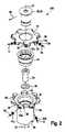
図1乃至図10は、本発明に従ったフライス工具の例示的な実施形態の様々な図と異なる状態を示す。様々な状態の図は、フライス工具の機能を説明するのに役立つ。フライス工具は、図1乃至図10の夫々に全体を符号100で示す。 1 to 10 show different states from the various diagrams of the exemplary embodiment of the milling tool according to the present invention. Figures of various states help explain the function of the milling tool. The milling tool is indicated by
フライス工具100は、フライス工具ホルダ10と、フライス工具ホルダ10に配置された複数の切削インサート12とを含む。前記切削インサートの4つは、図1の例として符号12a-12dを付している。純粋に説明の目的で、前記切削インサートには次のように連続符号が付されている。切削インサート12aは第1の切削インサートとして指定され、切削インサート12bは第2の切削インサートとして指定され、切削インサート12cは第3の切削インサートとして指定され、切削インサート12dは第4の切削インサートとして指定される。 The
本願に示す例示的な実施形態にて、全てで14個の切削インサート12がフライス工具ホルダに配置されている。しかしながら、本発明の動作方法に必要な切削インサート12の最小数は4つだけである。しかしながら、原則として、フライス工具100は、4つよりも多い任意の数の切削インサート12を含むことができる。本発明によるフライス工具100は、偶数個の切削インサート12を含むことが好ましい。 In the exemplary embodiment shown in the present application, a total of 14 cutting inserts 12 are arranged in the milling tool holder. However, the minimum number of cutting inserts 12 required for the operating method of the present invention is only four. However, in principle, the
本件の例示的な実施形態に従って、切削インサート12は締結ねじ14(図2を参照)によってフライス工具ホルダ10に取り外し可能に締結されている。切削インサート12は、この目的のために設けられた切削インサート受け部13に解放可能に配置され、図2の符号の例として、前記切削インサート受け部13a-13dのうちの4つだけが再び設けられている。切削インサート12a-12dの命名と同等の方法で、この場合の切削インサート受け部13a-13dは、次のようにも指定される。第1の切削インサート受け部13a、第2の切削インサート受け部13b、第3の切削インサート受け部13c及び第4の切削インサート受け部13d。 According to an exemplary embodiment of the present case, the cutting insert 12 is detachably fastened to the
しかし、切削インサート12を、例えばクランプ、はんだ付けまたは溶接などの別の方法でフライス工具ホルダ10に解放可能又は永久に固定することも同様に考えられる。締結の種類に関係なく、切削インサート12は超硬合金から製造されるのが好ましく、反対にフライス工具ホルダ10は鋼から製造されるのが好ましい。 However, it is also conceivable to releasably or permanently secure the cutting insert 12 to the
フライス工具ホルダ10は、複数の部品で構成されている。フライス工具ホルダは、第1のホルダ部16と第2のホルダ部18とを備える。2つのホルダ部16、18は、互いに対して移動可能である。取り付けられた状態では、これは当然ではない。しかし、2つのホルダ部16、18は、フライス加工幅を調整するためにユーザが選択可能な異なる位置に互いに位置決めすることができる。この場合、クランプねじ22を含むロック機構20により、2つのホルダ部16、18は、所望の位置(フライス加工幅の設定に対応する)で互いに対して固定又は固着することができる。2つのホルダ部16、18間の距離は、無段階に調整することができるのが好ましい。 The
今般の例示的な実施形態にて、フライス加工幅を調整するために、即ち、2つのホルダ部16、18の間の相対位置を変えるためにスペーサ要素24が役立つ。本場合に示された例示的な実施形態にて、スペーサ要素24は第1のホルダ部16内に螺合され得るスリーブとして構成される。見られるように、特に図3乃至図10にて及び以下に詳細に説明されるように、第1のホルダ部16と第2のホルダ部18との間の距離は、スペーサ要素24が第1のホルダ部16にねじ込まれれば進むほど小さくなる。これにより、フライス工具100の使用中に対応してより小さいフライス加工幅が得られる。逆に、スペーサ要素24が第1のホルダ部16との螺合から外れると、逆に、第1のホルダ部16と第2のホルダ部18との間の距離が大きくなり、それに応じて設定されるフライス加工幅が大きくなる。 In this exemplary embodiment, the
フライス工具100は、通常この目的のために設けられた工具受け部に固定される。この目的のために、第1のホルダ部16は、その下端に接続フランジ26を備えている。前記接続フランジ26は、フライス工具100を工具受け部に締結又は固定するための締結ねじ28及び関連するワッシャ30とともに機能する。 The
特に接続フランジ26の結果として、第1のホルダ部16は、断面がT字形にほぼ一致する実質的に細長い形をしている。反対に第2のホルダ部18は、実質的にディスク形状に構成されている。第2のホルダ部は、第1のホルダ部16の上側に配置される。以下により詳細に説明されるように、しかしながら、第2のホルダ部18は、軸方向において第1のホルダ部16上に直接載っているのではなく、スペーサ要素24上に載っている。 In particular, as a result of the connecting
両ホルダ部16、18は、フライス工具100全体としても、長手軸32に対して対称であるのが好ましい。2つのホルダ部16、18は取付け状態で、互いに入れ子になっている。また、歯車と同様に互いに噛み合っているとも言える。円周方向34、即ち長手軸32の周りで見たとき、第2のホルダ部18に関連付けられた切削インサート受け部13は、夫々第1のホルダ部16に配置された2つの切削インサート受け部13の間に配置される。逆に、第1のホルダ部16に関連付けられた切削インサート受け部13も、夫々第2のホルダ部18の2つの切削インサート受け部13の間に配置される。従って、例えば第3の切削インサート受け部13cは、円周方向に第1の切削インサート受け部13aと第2の切削インサート受け部13bとの間に配置され、第3の切削インサート受け部13cは、第2のホルダ部18に関連付けられ、第1及び第2の切削インサート受け部13a、13bは、第1のホルダ部16に関連付けられる。同様の方法で、第1のホルダ部16に関連付けられる第2の切削インサート受け部13bは、第2のホルダ部18に関連付けられる第3の切削インサート受け部13cと第4の切削インサート受け部13dとの間に配置される。第1のホルダ部16に配置され、第2のホルダ部18に配置されたトルク駆動面38に対応するトルク駆動面36は、第1のホルダ部16から第2のホルダ部18へのトルク伝達を処理する。互いに対応する前記トルク駆動面36、38は、長手軸32に垂直に配置され且つ円周方向34に垂直に配置された工具100の半径方向40に沿って延びるのが好ましい。トルク駆動面36、38は、半径方向40で少なくとも5°未満の角度で囲まれる。長手軸32に関して、トルク駆動面36、38は、長手軸に平行に延びるか、または僅かに傾斜している。 Both the
第1のホルダ部16に配置された切削インサート12は、第2のホルダ部18に配置された切削インサート12に対して異なる方向にフライス工具ホルダ10のヘッド部から突出する。第1のホルダ部16に配置された第1及び第2の切削インサート12a、12bは、例えば、フライス工具ホルダ10のヘッド部から下方に突出し、然るに第2のホルダ部18に配置された第3及び第4の切削インサート12c、12dは、フライス工具ホルダ10のヘッド部から上方に突出する。本件の場合において、「下方」及び「上方」という用語は、互いに反対方向に整列し、長手軸32に平行な2つの方向を意味する。第1のホルダ部16に配置された切削インサート12には、第2のホルダ部18に配置された切削インサートよりも若干異なる切削インサートが使用される。2つのホルダ部16、18に配置された切削インサートは、タイプに関して確かに基本的に同じであるが、それらは互いに鏡面反転した方法で構成されている。この点で技術用語では、これらは主に左右の切削インサートと呼ばれ、本事例では第1及び第2のホルダ部16、18の交互の列に配置される。この時点で、この場合の切削インサート12は、2つのホルダ部16、18に対して接線方向に配置されていることにも留意されたい。しかしながら、これは、本発明の実現のために絶対に必要というわけではない。切削インサート12は、本発明の範囲から逸脱することなく、同様に軸方向に、又はフライス工具ホルダ10上に別の位置合わせで配置することもできる。 The cutting insert 12 arranged in the
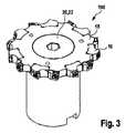
図3及び図4は、本発明に従ったフライス工具100の第1の状態を示し、フライス加工幅は最小値に設定されており、つまり、第1のホルダ部16と第2のホルダ部18の間の距離は可能な限り小さく、2つのホルダ部16、18はロック機構20又はクランプねじ22によって固定される。この場合、クランプねじ22は円錐形に形成された頭部で、対応するように形成された第2のホルダ部18の円錐形表面42を押圧する。その結果、クランプねじ22は、軸方向及び半径方向の両方で第2のホルダ部18に力を加える。しかしながら、スペーサ要素24は、クランプねじ22と接触していない。クランプねじ22は、スペーサ要素24に触れることなく、スペーサ要素24を通って第1のホルダ部16に螺合する。この目的のために、第1のホルダ部16の内部に設けられた雌ねじ46に対応する雄ねじ44が、クランプねじ22の下側に設けられている。両ねじ44、46は、ファインピッチねじとして構成されるのが好ましい。 3 and 4 show a first state of the
本事例にて示される例示的な実施形態にて、スペーサ要素24はまた第1のホルダ部16に螺合される。この目的のために、第1のホルダ部16の内側に配置された雌ねじ50に対応する雄ねじ48がスペーサ要素24の下端部に配備される。区別を簡単にするために、ねじ44-50は次のように指定される。スペーサ要素24に設けられた雄ねじ48は、第1のねじとして示されている。第1のホルダ部16に設けられた雌ねじ50は、第2のねじとして示されている。第1のホルダ部16にも設けられた雌ねじ46は、第3のねじとして示されている。クランプねじ22に配置された雄ねじ44は、第4のねじとして示されている。全てのねじ44-50はファインピッチねじであるのが好ましい。第1のホルダ部16に設けられたねじ46、50(第2及び第3のねじ)は、同軸に延びているが、長手軸32に沿って互いにずれているのが好ましい。 In the exemplary embodiment shown in this example, the
取付け状態にて、クランプねじ22は、とりわけ軸方向に第2のホルダ部18を押圧する。第2のホルダ18は、軸方向にスペーサ要素24上に載っている。この目的のために、スペーサ要素24及び第2のホルダ部18は夫々、環状の接触面52、54を備え、それに沿って前記2つの構成要素が互いに接触する。環状の接触面52、54は、軸方向の平面支持として機能する。これは、ぐらつきエラーを最小限に抑える目的で実質的に機能する。 In the mounted state, the
既に述べたように、スペーサ要素24は第1のホルダ部16内に螺合される。図4に示す状態にて、スペーサ要素24は、この目的のために第1のホルダ部16の内部に設けられた下部ストッパ56まで完全に螺合される。フライス工具100の軸方向の振れ公差と同心度公差をできるだけ小さく保つことができるように、スペーサ要素24と第1のホルダ部16との間及びスペーサ要素24と第2のホルダ部18との間には、半径方向にセンタリング手段として機能する隙間嵌めが夫々設けられている。長手軸32に対して対称に延び、本事例では第1の円筒面として示される円筒面58は、この目的のために第1のホルダ部16に設けられる。前記の第1の円筒面58は、スペーサ要素24の外周に設けられた円筒面60に対応する。長手軸32に対して対称に延びる円筒面62が、図4のさらに上部の第2のホルダ部18に同様の方法で設けられている。前記の円筒面62は、この場合、第2の円筒面として示されている。これは、スペーサ要素24の上端部の外周に設けられた円筒面64に対応する。円筒面58、60間及び円筒面62、64間にも隙間嵌めが提供されることが好ましい。第1の円筒面58は、第2の円筒面62と同軸に延びるのが好ましく、2つの円筒面58、62は、工具が取り付けられた状態で互いに軸方向にずれて配置される。 As already mentioned, the
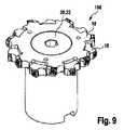
2つのホルダ部16、18間の距離、従ってフライス加工幅を変更するために、スペーサ要素24は、ねじ接続によって第1のホルダ部16に対して別の位置に移動しなければならない。この動作は例として図5乃至図8に示される。ここでは、調整アダプタ66を使用して、スペーサ要素24を螺合するか、螺合を解除する。図5及び図6は、スペーサ要素24が第1のホルダ部16に完全に(まだ)螺合している状態を示している。対照的に、図7及び図8は、スペーサ要素24が第1のホルダ部16からすでに部分的に螺合を外れており、2つのホルダ部16、18間のフライス加工幅又は距離が拡大している状態を示す。 In order to change the distance between the two
調整アダプタ66は、スペーサ要素24の内側の上端部の領域に配置された工具係合部68に係合する。本事例において、これは多面的な工具係合部である。前記の工具係合部68は、この場合、第1の工具係合部として指定される。調整アダプタ66の内部には、第2の工具係合部70がさらに設けられており、これにより調整アダプタ66を移動させることができる。本事例において、これはアレン工具係合部として構成されている。アレンキーを第2の工具係合部70内に挿入することにより、調整アダプタ66、従ってスペーサ要素24も非常に簡単に移動する。しかしながら、この時点で、本発明の範囲から逸脱することなく、工具係合部68、70について、他のタイプの工具係合部も明らかに使用できることに留意されたい。原則として、スペーサ要素24を手でホルダ部16に螺合させること、またはスペーサ要素を前記ホルダ部から手で螺合を解除することも可能である。 The
所定のフライス加工幅又は2つのホルダ部16、18間の所望の距離が設定されるとすぐに、2つのホルダ部16、18はロック機構20によって再び固定される。これは図9及び図10に示される。従って、図9及び図10に示す状態は、図3及び図4にも示されている取付け状態に再び対応し、2つのホルダ部16、18間の距離は、取付け状態と比較して拡大されている。 As soon as a predetermined milling width or a desired distance between the two
最後に、原則として、この場合の例として示される例示的な実施形態で使用されるクランプねじ22の代わりに、別のタイプのロック機構を使用できることに留意されたい。例えば、この目的からクランプ機構がまた使用され得る。 Finally, it should be noted that, in principle, another type of locking mechanism can be used in place of the
Claims (13)
Translated fromJapanese第1の切削インサート(12a)を受け入れるための第1の切削インサート受け部(13a)と、第2の切削インサート(12b)を受け入れるための第2の切削インサート受け部(13b)とを有する第1のホルダ部(16)と、
フライス加工幅を調整するために、長手軸(32)に沿って第1のホルダ部(16)に対して可変に配置され、第3の切削インサート(12c)を受け入れるための第3の切削インサート受け部(13c)と、第4の切削インサート(12d)を受け入れるための第4の切削インサート受け部(13d)とを有する第2のホルダ部(18)と、
第1のホルダ部(16)と第2のホルダ部(18)との間に配置されて、フライス加工幅を調整するように構成されたスペーサ要素(24)と、
調整されたフライス加工幅に第1及び第2のホルダ部(16、18)を固定するためのロック機構(20)とを備え、
第1のホルダ部(16)と第2のホルダ部(18)は、第3の切削インサート受け部(13c)が第1の切削インサート受け部(13a)と第2の切削インサート受け部(13b)との間に円周方向(34)に配置され、第2の切削インサート受け部(13b)が第3の切削インサート受け部(13c)と第4の切削インサート受け部(13d)との間に円周方向に配置されるように、取付け状態で互いに位置決めされ、
第1のホルダ部(16)は、スペーサ要素(24)を中心に置くように構成された第1の円筒面(58)を備え、第1の円筒面(58)は長手軸(32)に対して対称に延び、
第2のホルダ部(18)は、スペーサ要素(24)を中心に置くように構成された第2の円筒面(62)を含み、第2の円筒面(62)は長手軸(32)に対して対称に延び、
前記ロック機構(20)は、スペーサ要素(24)を通って第1のホルダ部(16)に配置された第3のねじ(46)に挿入されるクランプねじ(22)を含む、フライス工具ホルダ。Milling tool holder (10)
A second having a first cutting insert receiving portion (13a) for receiving a first cutting insert (12a) and a second cutting insert receiving portion (13b) for receiving a second cutting insert (12b). 1 holder part (16) and
A third cutting insert that is variably arranged with respect to the first holder portion (16) along the longitudinal axis (32) to accommodate the third cutting insert (12c) in order to adjust the milling width. A second holder portion (18) having a receiving portion (13c) and a fourth cutting insert receiving portion (13d) for receiving the fourth cutting insert (12d).
A spacer element (24) arranged between the first holder portion (16) and the second holder portion (18) and configured to adjust the milling width,
A locking mechanism (20) for fixing the first and second holder portions (16, 18) to the adjusted milling width is provided.
In the first holder portion (16) and the second holder portion (18), the third cutting insert receiving portion (13c) has the first cutting insert receiving portion (13a) and the second cutting insert receiving portion (13b). ) In the circumferential direction (34), and a second cutting insert receiving portion (13b) is located between the third cutting insert receiving portion (13c) and the fourth cutting insert receiving portion (13d). Positioned from each other in the mounted state so that they are arranged in the circumferential direction.
The first holder portion (16) comprises a first cylindrical surface (58) configured to center the spacer element (24), with the first cylindrical surface (58) on the longitudinal axis (32). On the other hand, it extends symmetrically
The second holder portion (18) includes a second cylindrical surface (62) configured to center the spacer element (24), the second cylindrical surface (62) on the longitudinal axis (32). On the other hand, it extends symmetrically
The locking mechanism (20) includes a milling tool holder that includes a clamp screw (22) that is inserted through a spacer element (24) into a third screw (46) located in the first holder portion (16). ..
請求項1乃至11の何れかに記載のフライス工具ホルダ(10)と、
第1の切削インサート受け部(13a)内に配置された第1の切削インサート(12a)と、
第2の切削インサート受け部(13b)内に配置された第2の切削インサート(12b)と、
第3の切削インサート受け部(13c)内に配置された第3の切削インサート(12c)と、
第4の切削インサート受け部(13d)内に配置された第4の切削インサート(12d)と、
を備えた、フライス工具。A milling tool (100)
The milling tool holder (10) according to any one of claims 1 to11 .
The first cutting insert (12a) arranged in the first cutting insert receiving portion (13a),
With the second cutting insert (12b) arranged in the second cutting insert receiving portion (13b),
With the third cutting insert (12c) arranged in the third cutting insert receiving portion (13c),
With the fourth cutting insert (12d) arranged in the fourth cutting insert receiving portion (13d),
With a milling tool.
Applications Claiming Priority (3)
| Application Number | Priority Date | Filing Date | Title |
|---|---|---|---|
| DE102017131001.0 | 2017-12-21 | ||
| DE102017131001.0ADE102017131001A1 (en) | 2017-12-21 | 2017-12-21 | Milling tool holder and milling tool |
| PCT/EP2018/085966WO2019121998A1 (en) | 2017-12-21 | 2018-12-19 | Milling tool holder and milling tool |
Publications (3)
| Publication Number | Publication Date |
|---|---|
| JP2020534169A JP2020534169A (en) | 2020-11-26 |
| JP2020534169A5 JP2020534169A5 (en) | 2021-01-14 |
| JP7063983B2true JP7063983B2 (en) | 2022-05-09 |
Family
ID=64870495
Family Applications (1)
| Application Number | Title | Priority Date | Filing Date |
|---|---|---|---|
| JP2020515703AActiveJP7063983B2 (en) | 2017-12-21 | 2018-12-19 | Milling tool holder and milling tool |
Country Status (9)
| Country | Link |
|---|---|
| US (1) | US11484954B2 (en) |
| EP (1) | EP3703893B1 (en) |
| JP (1) | JP7063983B2 (en) |
| CN (1) | CN111212700B (en) |
| CA (1) | CA3074661A1 (en) |
| DE (1) | DE102017131001A1 (en) |
| MX (1) | MX2020002602A (en) |
| RU (1) | RU2735701C1 (en) |
| WO (1) | WO2019121998A1 (en) |
Families Citing this family (5)
| Publication number | Priority date | Publication date | Assignee | Title |
|---|---|---|---|---|
| EP3782751B1 (en)* | 2019-08-21 | 2024-05-29 | Seco Tools Ab | A milling cutter |
| CN111215679A (en)* | 2019-11-05 | 2020-06-02 | 合肥百恒设备模具有限公司 | Reverse milling cutter structure |
| CN113145912B (en)* | 2021-01-19 | 2024-09-17 | 西安海纳精密机械有限公司 | Adjustable three-edge milling cutter disc and adjusting method |
| CN119426684B (en)* | 2024-12-04 | 2025-08-01 | 宜昌永鑫精工科技股份有限公司 | Milling cutter dish convenient to adjust station |
| CN119589003A (en)* | 2024-12-23 | 2025-03-11 | 乐客精密工具(太仓)有限公司 | Indexable face milling cutter |
Citations (6)
| Publication number | Priority date | Publication date | Assignee | Title |
|---|---|---|---|---|
| US20060086424A1 (en) | 2002-05-29 | 2006-04-27 | Gavriel Spector | Slotter having cutters with adjustable width |
| JP2010000569A (en) | 2008-06-20 | 2010-01-07 | Toyota Motor Corp | Grinder and cutting device |
| CN203526662U (en) | 2013-09-17 | 2014-04-09 | 郧西县神风实业有限公司 | Milling inner barrier surface turnable cutter disc |
| WO2015104730A1 (en) | 2014-01-10 | 2015-07-16 | SCHIAVON S.r.l. | Mechanical device for a dynamic adjustment of rotary tools |
| CN106312160A (en) | 2016-09-22 | 2017-01-11 | 成都飞机工业(集团)有限责任公司 | Gang cutter with changeable edge width |
| DE102017110754A1 (en) | 2017-05-17 | 2018-11-22 | Leitz Gmbh & Co. Kg | Tool device, in particular milling tool |
Family Cites Families (19)
| Publication number | Priority date | Publication date | Assignee | Title |
|---|---|---|---|---|
| DE192233C (en)* | ||||
| DE536135C (en)* | 1929-03-23 | 1931-10-19 | Henning Larsson | Multi-part slot and shape milling cutter |
| US2592382A (en)* | 1947-03-06 | 1952-04-08 | Phillipe J Blais | Adjustable milling cutter |
| AT189883B (en)* | 1955-07-11 | 1957-05-10 | Josef Weisz | Claw-coupled adjustable slot milling cutter |
| DE1179080B (en)* | 1959-11-05 | 1964-10-01 | Friedrich Link | Two-part disc milling cutter |
| CH588337A5 (en)* | 1975-01-06 | 1977-05-31 | Oertli Werkzeuge Ag | |
| SU848188A1 (en)* | 1975-10-20 | 1981-07-23 | Предприятие П/Я Р-6760 | Side built-up milling cutter |
| DE2754499A1 (en)* | 1977-12-07 | 1979-06-13 | Hans Heinlein | Micrometer adjustment for tool indexable cutter - has cylindrical body for displacing and clamping indexable plate about parallel rotating cylinder |
| JPS5921722B2 (en)* | 1978-10-26 | 1984-05-22 | 三菱マテリアル株式会社 | Staggered blade turning tool |
| SU908553A1 (en)* | 1980-06-05 | 1982-02-28 | Краматорский Научно-Исследовательский И Проектно-Технологический Институт Машиностроения | Mechanism for adjusting milling cutters at working grooves |
| SU1296318A1 (en)* | 1984-02-08 | 1987-03-15 | Предприятие П/Я Р-6491 | End-milling cutter |
| CN88211122U (en)* | 1988-03-04 | 1988-11-09 | 李旭淮 | Adjustable vertical milling tool without refucing |
| US4936717A (en)* | 1988-12-19 | 1990-06-26 | Gte Valenite Corporation | Adjustable narrow width slotting cutter |
| DE8910441U1 (en)* | 1989-09-01 | 1989-11-02 | Wilhelm Fette Gmbh, 2053 Schwarzenbek | Disc milling cutter with indexable inserts and adjustable cutting width |
| KR101160725B1 (en)* | 2006-04-28 | 2012-06-28 | 유니온쓰루 가부시키가이샤 | Rotary cutting tool |
| DE102007001864A1 (en)* | 2007-01-12 | 2008-07-17 | Kennametal Inc. | milling |
| DE102009022051B3 (en)* | 2009-05-18 | 2010-09-30 | Leitz Gmbh & Co. Kg | Cutting tool is clamped on drive shaft by clamping device and has tool part that is connected with clamping device, where another tool part is adjustable in axial direction |
| SE535541C2 (en) | 2011-02-11 | 2012-09-18 | Sandvik Intellectual Property | Cutting insert for a milling tool designed for tooth milling |
| AT13700U1 (en) | 2013-08-06 | 2014-06-15 | Ceratizit Austria Gmbh | Burr-cutting insert |
- 2017
- 2017-12-21DEDE102017131001.0Apatent/DE102017131001A1/ennot_activeCeased
- 2018
- 2018-12-19MXMX2020002602Apatent/MX2020002602A/enunknown
- 2018-12-19CACA3074661Apatent/CA3074661A1/ennot_activeAbandoned
- 2018-12-19JPJP2020515703Apatent/JP7063983B2/enactiveActive
- 2018-12-19CNCN201880067125.2Apatent/CN111212700B/enactiveActive
- 2018-12-19WOPCT/EP2018/085966patent/WO2019121998A1/ennot_activeCeased
- 2018-12-19EPEP18826016.0Apatent/EP3703893B1/enactiveActive
- 2018-12-19RURU2020109573Apatent/RU2735701C1/enactive
- 2020
- 2020-03-03USUS16/807,363patent/US11484954B2/enactiveActive
Patent Citations (6)
| Publication number | Priority date | Publication date | Assignee | Title |
|---|---|---|---|---|
| US20060086424A1 (en) | 2002-05-29 | 2006-04-27 | Gavriel Spector | Slotter having cutters with adjustable width |
| JP2010000569A (en) | 2008-06-20 | 2010-01-07 | Toyota Motor Corp | Grinder and cutting device |
| CN203526662U (en) | 2013-09-17 | 2014-04-09 | 郧西县神风实业有限公司 | Milling inner barrier surface turnable cutter disc |
| WO2015104730A1 (en) | 2014-01-10 | 2015-07-16 | SCHIAVON S.r.l. | Mechanical device for a dynamic adjustment of rotary tools |
| CN106312160A (en) | 2016-09-22 | 2017-01-11 | 成都飞机工业(集团)有限责任公司 | Gang cutter with changeable edge width |
| DE102017110754A1 (en) | 2017-05-17 | 2018-11-22 | Leitz Gmbh & Co. Kg | Tool device, in particular milling tool |
Also Published As
| Publication number | Publication date |
|---|---|
| EP3703893B1 (en) | 2022-09-28 |
| JP2020534169A (en) | 2020-11-26 |
| CN111212700A (en) | 2020-05-29 |
| US11484954B2 (en) | 2022-11-01 |
| US20200198028A1 (en) | 2020-06-25 |
| EP3703893A1 (en) | 2020-09-09 |
| MX2020002602A (en) | 2020-10-01 |
| WO2019121998A1 (en) | 2019-06-27 |
| CA3074661A1 (en) | 2019-06-27 |
| DE102017131001A1 (en) | 2019-06-27 |
| CN111212700B (en) | 2021-07-13 |
| RU2735701C1 (en) | 2020-11-06 |
Similar Documents
| Publication | Publication Date | Title |
|---|---|---|
| JP7063983B2 (en) | Milling tool holder and milling tool | |
| JPH0435297B2 (en) | ||
| JP5474051B2 (en) | Tool for workpiece turning, turn broaching or outside milling | |
| RU2549815C2 (en) | Instrumental joint | |
| RU2521541C2 (en) | Tool holder and tool arbour | |
| US4615688A (en) | Coupling device | |
| KR101690361B1 (en) | Milling tool | |
| RU2111093C1 (en) | Milling head | |
| US20020015623A1 (en) | Rotatable tool having a replaceable tip at the chip removing free end of the tool | |
| EP0997216B1 (en) | Milling tool | |
| KR970006236B1 (en) | Fine adjustment mechanism for a toolholder | |
| US8511942B2 (en) | Machine tool with adjustable cutting insert | |
| US7114890B2 (en) | Cutting tool adjustment device | |
| JP2020534169A5 (en) | ||
| KR20040058320A (en) | Tool for chip removing machining with adjustable insert | |
| JP4227955B2 (en) | Cutting tools | |
| RU2572945C2 (en) | Cutting tool with regulating ring installed of shank | |
| US4547997A (en) | Adjustable tool mount | |
| JP5955959B2 (en) | Adjustable cutting tools | |
| SE460958B (en) | TOOLS FOR CUTTING OUT THREADS | |
| JP7156139B2 (en) | Cutting inserts and milling tools | |
| CN109311108A (en) | Hobbing tools with replaceable cutting inserts | |
| EP0659511B1 (en) | Tool system | |
| US3764224A (en) | Adjustable chucking reamer | |
| RU2768927C1 (en) | Threading milling tool |
Legal Events
| Date | Code | Title | Description |
|---|---|---|---|
| A521 | Request for written amendment filed | Free format text:JAPANESE INTERMEDIATE CODE: A523 Effective date:20200318 | |
| A621 | Written request for application examination | Free format text:JAPANESE INTERMEDIATE CODE: A621 Effective date:20200318 | |
| A131 | Notification of reasons for refusal | Free format text:JAPANESE INTERMEDIATE CODE: A131 Effective date:20210525 | |
| A521 | Request for written amendment filed | Free format text:JAPANESE INTERMEDIATE CODE: A523 Effective date:20210813 | |
| A131 | Notification of reasons for refusal | Free format text:JAPANESE INTERMEDIATE CODE: A131 Effective date:20220111 | |
| A521 | Request for written amendment filed | Free format text:JAPANESE INTERMEDIATE CODE: A523 Effective date:20220224 | |
| TRDD | Decision of grant or rejection written | ||
| A01 | Written decision to grant a patent or to grant a registration (utility model) | Free format text:JAPANESE INTERMEDIATE CODE: A01 Effective date:20220405 | |
| A61 | First payment of annual fees (during grant procedure) | Free format text:JAPANESE INTERMEDIATE CODE: A61 Effective date:20220421 | |
| R150 | Certificate of patent or registration of utility model | Ref document number:7063983 Country of ref document:JP Free format text:JAPANESE INTERMEDIATE CODE: R150 | |
| R250 | Receipt of annual fees | Free format text:JAPANESE INTERMEDIATE CODE: R250 |