JP7063629B2 - Non-slip surgical instrument to prepare holes in bone tissue - Google Patents
Non-slip surgical instrument to prepare holes in bone tissueDownload PDFInfo
- Publication number
- JP7063629B2 JP7063629B2JP2018003161AJP2018003161AJP7063629B2JP 7063629 B2JP7063629 B2JP 7063629B2JP 2018003161 AJP2018003161 AJP 2018003161AJP 2018003161 AJP2018003161 AJP 2018003161AJP 7063629 B2JP7063629 B2JP 7063629B2
- Authority
- JP
- Japan
- Prior art keywords
- surgical instrument
- slip
- flutes
- certain embodiments
- drill
- Prior art date
- Legal status (The legal status is an assumption and is not a legal conclusion. Google has not performed a legal analysis and makes no representation as to the accuracy of the status listed.)
- Active
Links
- 210000000988bone and boneAnatomy0.000titleclaimsdescription133
- 238000001356surgical procedureMethods0.000claimsdescription48
- 238000002627tracheal intubationMethods0.000claimsdescription25
- 230000035515penetrationEffects0.000claimsdescription13
- 239000003086colorantSubstances0.000claimsdescription12
- 238000002316cosmetic surgeryMethods0.000claimsdescription12
- 238000000034methodMethods0.000description76
- 238000002474experimental methodMethods0.000description40
- 230000033001locomotionEffects0.000description21
- 238000005553drillingMethods0.000description16
- 239000013013elastic materialSubstances0.000description12
- 238000003780insertionMethods0.000description10
- 230000037431insertionEffects0.000description10
- 230000002265preventionEffects0.000description10
- 238000003801millingMethods0.000description9
- 239000012636effectorSubstances0.000description8
- 210000001519tissueAnatomy0.000description8
- 239000000463materialSubstances0.000description7
- 238000010586diagramMethods0.000description4
- 206010003246arthritisDiseases0.000description3
- 238000005516engineering processMethods0.000description3
- 230000004927fusionEffects0.000description3
- 210000004283incisorAnatomy0.000description2
- 230000001965increasing effectEffects0.000description2
- 208000014674injuryDiseases0.000description2
- 239000002184metalSubstances0.000description2
- 230000008569processEffects0.000description2
- 230000002792vascularEffects0.000description2
- 206010033799ParalysisDiseases0.000description1
- 208000027418Wounds and injuryDiseases0.000description1
- 230000002159abnormal effectEffects0.000description1
- 230000005856abnormalityEffects0.000description1
- 210000001367arteryAnatomy0.000description1
- 230000002917arthritic effectEffects0.000description1
- 230000008859changeEffects0.000description1
- 238000004040coloringMethods0.000description1
- 230000006378damageEffects0.000description1
- 230000001419dependent effectEffects0.000description1
- 210000002745epiphysisAnatomy0.000description1
- 230000005484gravityEffects0.000description1
- 238000000227grindingMethods0.000description1
- 239000007943implantSubstances0.000description1
- 230000001939inductive effectEffects0.000description1
- 230000009545invasionEffects0.000description1
- 238000002324minimally invasive surgeryMethods0.000description1
- 210000000653nervous systemAnatomy0.000description1
- 238000002360preparation methodMethods0.000description1
- 210000003625skullAnatomy0.000description1
- 210000004872soft tissueAnatomy0.000description1
- 210000000278spinal cordAnatomy0.000description1
- 230000000087stabilizing effectEffects0.000description1
- 238000012360testing methodMethods0.000description1
- 230000008733traumaEffects0.000description1
- 238000012795verificationMethods0.000description1
Images


Classifications
- A—HUMAN NECESSITIES
- A61—MEDICAL OR VETERINARY SCIENCE; HYGIENE
- A61B—DIAGNOSIS; SURGERY; IDENTIFICATION
- A61B17/00—Surgical instruments, devices or methods
- A61B17/16—Instruments for performing osteoclasis; Drills or chisels for bones; Trepans
- A61B17/1662—Instruments for performing osteoclasis; Drills or chisels for bones; Trepans for particular parts of the body
- A61B17/1671—Instruments for performing osteoclasis; Drills or chisels for bones; Trepans for particular parts of the body for the spine
- A—HUMAN NECESSITIES
- A61—MEDICAL OR VETERINARY SCIENCE; HYGIENE
- A61B—DIAGNOSIS; SURGERY; IDENTIFICATION
- A61B17/00—Surgical instruments, devices or methods
- A61B17/16—Instruments for performing osteoclasis; Drills or chisels for bones; Trepans
- A61B17/1613—Component parts
- A61B17/1615—Drill bits, i.e. rotating tools extending from a handpiece to contact the worked material
- A—HUMAN NECESSITIES
- A61—MEDICAL OR VETERINARY SCIENCE; HYGIENE
- A61B—DIAGNOSIS; SURGERY; IDENTIFICATION
- A61B34/00—Computer-aided surgery; Manipulators or robots specially adapted for use in surgery
- A61B34/30—Surgical robots
- A—HUMAN NECESSITIES
- A61—MEDICAL OR VETERINARY SCIENCE; HYGIENE
- A61B—DIAGNOSIS; SURGERY; IDENTIFICATION
- A61B90/00—Instruments, implements or accessories specially adapted for surgery or diagnosis and not covered by any of the groups A61B1/00 - A61B50/00, e.g. for luxation treatment or for protecting wound edges
- A61B90/90—Identification means for patients or instruments, e.g. tags
- A61B90/92—Identification means for patients or instruments, e.g. tags coded with colour
- A—HUMAN NECESSITIES
- A61—MEDICAL OR VETERINARY SCIENCE; HYGIENE
- A61B—DIAGNOSIS; SURGERY; IDENTIFICATION
- A61B17/00—Surgical instruments, devices or methods
- A61B17/16—Instruments for performing osteoclasis; Drills or chisels for bones; Trepans
- A61B2017/1602—Mills
- A—HUMAN NECESSITIES
- A61—MEDICAL OR VETERINARY SCIENCE; HYGIENE
- A61B—DIAGNOSIS; SURGERY; IDENTIFICATION
- A61B90/00—Instruments, implements or accessories specially adapted for surgery or diagnosis and not covered by any of the groups A61B1/00 - A61B50/00, e.g. for luxation treatment or for protecting wound edges
- A61B90/03—Automatic limiting or abutting means, e.g. for safety
- A61B2090/033—Abutting means, stops, e.g. abutting on tissue or skin
- A61B2090/034—Abutting means, stops, e.g. abutting on tissue or skin abutting on parts of the device itself
- A61B2090/035—Abutting means, stops, e.g. abutting on tissue or skin abutting on parts of the device itself preventing further rotation
- A—HUMAN NECESSITIES
- A61—MEDICAL OR VETERINARY SCIENCE; HYGIENE
- A61B—DIAGNOSIS; SURGERY; IDENTIFICATION
- A61B90/00—Instruments, implements or accessories specially adapted for surgery or diagnosis and not covered by any of the groups A61B1/00 - A61B50/00, e.g. for luxation treatment or for protecting wound edges
- A61B90/06—Measuring instruments not otherwise provided for
- A61B2090/062—Measuring instruments not otherwise provided for penetration depth
Landscapes
- Health & Medical Sciences (AREA)
- Surgery (AREA)
- Life Sciences & Earth Sciences (AREA)
- Engineering & Computer Science (AREA)
- Heart & Thoracic Surgery (AREA)
- Animal Behavior & Ethology (AREA)
- Veterinary Medicine (AREA)
- Biomedical Technology (AREA)
- Nuclear Medicine, Radiotherapy & Molecular Imaging (AREA)
- Medical Informatics (AREA)
- Molecular Biology (AREA)
- Public Health (AREA)
- General Health & Medical Sciences (AREA)
- Oral & Maxillofacial Surgery (AREA)
- Dentistry (AREA)
- Orthopedic Medicine & Surgery (AREA)
- Pathology (AREA)
- Robotics (AREA)
- Surgical Instruments (AREA)
Description
Translated fromJapanese関連出願の相互参照
本出願は、「骨組織に穴を準備する滑り止め付き手術用器具(Anti-Skid Surgical Instrument for use in Preparing Holes in Bone Tissue)」と題する、2016年1月13日出願の米国仮特許出願第62/278,313号と、「骨組織に穴を準備する滑り止め付き手術用器具(Anti-Skid Surgical Instrument for use in Preparing Holes in Bone Tissue)」と題する、2016年9月16日に出願の米国仮特許出願第62/395,795号の優先権を主張し、「骨組織に穴を準備する滑り止め付き手術用器具(Anti-Skid Surgical Instrument for use in Preparing Holes in Bone Tissue)」と題する、2014年7月14日出願の米国特許出願第62/024,402号の優先権を主張する、「骨組織に穴を準備する滑り止め付き手術用器具(Anti-Skid Surgical Instrument for use in Preparing Holes in Bone Tissue)」と題する、2015年7月14日出願の米国特許出願第14/799,170号の一部継続出願であり、それぞれの内容全体が本明細書に参考として組み込まれる。Mutual reference to related applications This application is filed on January 13, 2016, entitled "Anti-Skid Surgical Instrument for Use in Preparing Holes in Bone Tissue". US Provisional Patent Application No. 62 / 278,313 and September 2016, entitled "Anti-Skid Surgical Instrument for us in Preparing Holes in Bone Tissue" Claiming the priority of US provisional patent application No. 62 / 395,795 filed on the 16th, "Anti-Skid Structural Instrument for use Holes in Bone""Anti-SkidSurgical", which claims the priority of US Patent Application No. 62 / 024,402 filed on July 14, 2014, entitled "Tissue". This is a partial continuation of US Patent Application No. 14 / 799,170 filed on July 14, 2015, entitled "Instrument for us in Preparing Holes in Bone Tissue", the entire contents of which are referred to herein. Is incorporated as.
本発明は、手術中に骨組織に穴を準備する際に使用する、滑り止め付き手術用器具に関する。 The present invention relates to non-slip surgical instruments used to prepare holes in bone tissue during surgery.
脊椎手術では、正確に穴をあけ、骨組織へスクリュー又はその他の器具を正確に配置することがよく求められる。脊椎手術中の穴あけ又は本体の操作が不適切であると、脊髄や動脈に近接しているため、致命的な損傷や死を招き得る。さらに、成功させるためには通常、正確な配置が必要である。例えば、脊椎固定は通常、骨を癒着しやすくするための、金属スクリュー、ロッド、プレートのような固定装置で椎体を安定させることによって補強される。脊椎固定では、他の手術と同様に、スクリューを骨の中に配置する正確性が、処置の結果に直接影響を及ぼす。治療しようとしている2つの骨の間の動きが少なければ少ないほど、骨が上手く癒着する変化も大きくなる。固定装置を使用することにより、脊椎固定処置の成功率が大幅に上がってきている。Spine surgery often requires accurate drilling and accurate placement of screws or other instruments in bone tissue. Improper drilling or manipulation of the body during spinal surgery can result in fatal injury or death due to its proximity to the spinal cord and arteries. In addition, accurate placement is usually required for success. For example, spinal fusion is usually reinforced by stabilizing the vertebral body with fixation devices such as metal screws, rods, and plates to facilitate bone adhesion. In spinal fusion, as in any surgery, the accuracy of placing the screw in the bone directly affects the outcome of the procedure. The less movement between the two bones being treated, the greater the change in how well the bones adhere. The use of fixation devices has significantly increased the success rate of spinal fusion procedures.
そのような処置は、外科医の技能に大きく左右され、その成功率は、様々な外科医の間で大きなばらつきがある。多くのナビゲーショナルな方法や検証方法が開発されてきた。しかしながら、そのような手術処置では、スクリューの誤配置の問題が未だによく起こっている。スクリューを挿入する前に開けられた穴が不正確なため、スクリューがずれる可能性がある。ドリルのチップが骨組織に接触するとき、ドリルのチップの角度によってドリルビットが滑る原因となり得、それによって不正確な軌道に沿って穴が開けられてしまう。通常、骨ドリルが骨の表面に対して90度で駆動されなければ、ドリルビットが骨の表面を滑る傾向があり、それによって不適切に穴を配置してしまう。よって、手術用器具が骨に接触したときに器具が滑るリスクを最小限にしつつ、患者の骨に穴を準備する滑り止め付き手術用器具が必要とされている。 Such procedures are highly dependent on the skill of the surgeon and their success rates vary widely among the various surgeons. Many navigational and verification methods have been developed. However, the problem of screw misplacement is still common in such surgical procedures. The holes made before inserting the screw are inaccurate and may cause the screw to shift. When the tip of the drill comes into contact with the bone tissue, the angle of the tip of the drill can cause the drill bit to slip, which causes a hole to be drilled along an inaccurate trajectory. Normally, if the bone drill is not driven at 90 degrees to the surface of the bone, the drill bit tends to slide on the surface of the bone, thereby improperly placing the hole. Therefore, there is a need for non-slip surgical instruments that prepare holes in the patient's bone while minimizing the risk of the instrument slipping when it comes into contact with the bone.
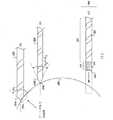
骨組織に穴を準備するのに使用する、滑り止め付き手術用器具が本明細書で説明されている。開示された手術用器具は、手術(例、脊椎手術、椎弓根スクリュー配置、髄内スクリュー配置)中に、骨組織に正確な穴を準備する能力を提供する。開示された手術用器具は、ドリル軸と骨組織の表面との間の角度が垂直であるかどうかに関わらず、正確に穴を配置することができる。開示された技術は、手術用器具の本体表面に対して垂直な、平らな穴あけ面を具備する。これによって、手術用器具が骨組織の表面で滑る可能性を低減させ、それによって穴の精度を上げる。 Non-slip surgical instruments used to prepare holes in bone tissue are described herein. The disclosed surgical instruments provide the ability to prepare accurate holes in bone tissue during surgery (eg, spinal surgery, pedicle screw placement, intramedullary screw placement). The disclosed surgical instruments can accurately place holes regardless of whether the angle between the drill axis and the surface of the bone tissue is vertical. The disclosed technique comprises a flat drilling surface perpendicular to the body surface of the surgical instrument. This reduces the likelihood that the surgical instrument will slip on the surface of the bone tissue, thereby increasing the accuracy of the hole.
一態様では、開示された技術は、手術中に患者の骨組織に穴を準備するための手術用ロボットシステムを具備し、手術用ロボットシステムは、
手術用器具ガイドが取付けられたエンドエフェクタを有するロボットアームであって、手術用器具ガイドが、滑り止め付き手術用器具を通る移動を保持及び/又は制限するよう配置され、
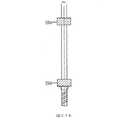
細長構造を有する滑り止め付き手術用器具が、
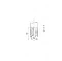
滑り止め付き手術用器具が骨組織と接触するとき手術用器具の滑り(例、手術用器具の意図しない横移動)が低減された状態で骨組織を取り除くための、細長構造の端部にあるミルヘッドであって、
細長構造の長手方向軸に実質的に垂直である平端部と、細長構造の長手方向軸を中心に骨組織内に切り込むための1つ又は複数の側面切削フルートを有するミルヘッドと、
ミルヘッドから延在するスパイクと、
ドリルに接続するためのシャンクと、
ミルヘッドとシャンクとの間のシャフトであって、取り除いた骨組織を逃がすための1つ又は複数のドリルフルート(例、非切削フルート)を有するシャフトと、を備える滑り止め付き手術用器具と、を備えるロボットアームを具備する、手術用ロボットシステム。In one aspect, the disclosed technique comprises a surgical robotic system for preparing a hole in a patient's bone tissue during surgery, the surgical robotic system.
A robotic arm with an end effector fitted with a surgical instrument guide, the surgical instrument guide is arranged to hold and / or limit movement through the non-slip surgical instrument.
Non-slip surgical instruments with an elongated structure,
Non-slip at the end of the elongated structure to remove the bone tissue with reduced slip (eg, unintended lateral movement of the surgical instrument) when the surgical instrument comes into contact with the bone tissue. It ’s a mill head,
A mill head with a flat end that is substantially perpendicular to the longitudinal axis of the elongated structure and one or more side cutting flutes for cutting into the bone tissue centered on the longitudinal axis of the elongated structure.
With spikes extending from the mill head,
With a shank to connect to the drill,
A non-slip surgical instrument comprising a shaft between the mill head and the shank, the shaft having one or more drill flutes (eg, non-cut flutes) to allow the removed bone tissue to escape. A surgical robot system equipped with a robot arm.
ある実施形態では、ミルヘッドは、凹状面を備え、その凹状面からスパイクが延在する。 In certain embodiments, the mill head comprises a concave surface in which spikes extend from the concave surface.
ある実施形態では、器具は、ミルヘッドからのエネルギーを吸収するコンプライアント部を具備する。 In certain embodiments, the instrument comprises a compliant portion that absorbs energy from the mill head.
ある実施形態では、器具は、手術用器具内に挿管を具備する。 In certain embodiments, the instrument comprises an intubation within the surgical instrument.
ある実施形態では、挿管は、細長構造の端部(例、手術用器具のチップ)に穴を備える。 In one embodiment, the intubation comprises a hole in the end of the elongated structure (eg, the tip of a surgical instrument).
ある実施形態では、コンプライアント部は、弾性材料、ゴム、ベロー、自在継手のうち少なくとも1つを備える。 In certain embodiments, the compliant portion comprises at least one of an elastic material, rubber, bellows, and universal joint.
ある実施形態では、コンプライアント部は、滑り止め付き手術用器具の第1部分を滑り止め付き手術用器具の第2部分に接続する。 In one embodiment, the compliant portion connects the first portion of the non-slip surgical instrument to the second portion of the non-slip surgical instrument.
ある実施形態では、第1部分がミルヘッドとシャフトの一部を備え、第2部分がシャンクとシャフトの一部を備える。 In one embodiment, the first portion comprises a mill head and a portion of the shaft, and the second portion comprises a shank and a portion of the shaft.
ある実施形態では、コンプライアント部は、シャンクの少なくとも一部を覆う。ある実施形態では、コンプライアント部は、シャフトの少なくとも一部を覆う。 In certain embodiments, the compliant portion covers at least a portion of the shank. In certain embodiments, the compliant portion covers at least a portion of the shaft.
ある実施形態では、コンプライアント部は、シャフトとシャンクの少なくとも一部を覆う。 In one embodiment, the compliant portion covers at least a portion of the shaft and shank.
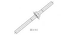
ある実施形態では、器具は、深度制御を具備する。 In certain embodiments, the instrument comprises depth control.
ある実施形態では、深度制御は、挿入深度を示す1つ又は複数のマーキング及び1つ又は複数の色のうち少なくとも一方を備える。 In certain embodiments, the depth control comprises at least one of one or more markings indicating the insertion depth and one or more colors.
ある実施形態では、深度制御は、滑り止め付き手術用器具の回転開始時を表示する第1部分と、滑り止め付き手術用器具の回転停止時及び深さ方向への侵入(depth penetration)の停止時のうち少なくともえ一方を表示する第2部分とを備える。 In one embodiment, the depth control has a first portion that indicates when the non-slip surgical instrument starts to rotate, and when the non-slip surgical instrument stops rotating and stops the depth penetration. It has a second part that displays at least one of the times.
ある実施形態では、深度制御は、深さ止めの位置が変更されたら、滑り止め付き手術用器具の侵入深度が変更するよう、滑り止め付き手術用器具に調節可能に取り付けられた深さ止めを備える。
In one embodiment, the depth control provides an adjustable depth stop on the non-slip surgical instrument so that the penetration depth of the non-slip surgical instrument changes when the position of the depth stop is changed. Be prepared.
ある実施形態では、シャフトは1つ又は複数のノッチを備え、深度制御は、滑り止め付き手術用器具に取り付けられると、1つ又は複数のノッチのうち少なくとも1つに係合する。 In certain embodiments, the shaft comprises one or more notches and the depth control engages at least one of the one or more notches when attached to a non-slip surgical instrument.
ある実施形態では、システムはシャフトとシャンクとの間に位置する工具サポートを備え、工具サポートは、ガイドによって画定された軸に沿って、手術用器具ガイドをスライドして通るような形状及びサイズとされ、工具サポートの径は、シャンクの径よりも大きい。 In one embodiment, the system comprises a tool support located between the shaft and the shank, which is shaped and sized to slide the surgical instrument guide along an axis defined by the guide. The diameter of the tool support is larger than the diameter of the shank.
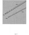
ある実施形態では、ミルヘッドの端部が、骨組織内に軸方向に切り込む1つ又は複数の端部切削フルートを有する。 In one embodiment, the end of the mill head has one or more end cutting flutes that cut axially into the bone tissue.
ある実施形態では、1つ又は複数のドリルフルートは、少なくとも2、3、4、6、8、10、又は20のフルートを備える。 In certain embodiments, the one or more drill flutes comprises at least 2, 3, 4, 6, 8, 10, or 20 flutes.
ある実施形態では、1つ又は複数の側面切削フルートは、少なくとも2、3、4、6、8、10、又は20のフルートを備える。 In certain embodiments, the one or more side cutting flutes comprises at least 2, 3, 4, 6, 8, 10, or 20 flutes.
ある実施形態では、シャフトの長手方向長は、ミルヘッドの長手方向長より大きい。
ある実施形態では、シャフトの長手方向長は、シャンクの長手方向長より大きい。In certain embodiments, the longitudinal length of the shaft is greater than the longitudinal length of the mill head.
In certain embodiments, the longitudinal length of the shaft is greater than the longitudinal length of the shank.
ある実施形態では、1つ又は複数のドリルフルートは、1つ又は複数の側面切削フルートよりも高いねじれ率(すなわち、より大きいフルート角度)を有するか、又は、1つ又は複数のドリルフルートは、1つ又は複数の側面切削フルートよりも低いねじれ率(すなわち、より小さいフルート角度)を有する。 In certain embodiments, the one or more drill flutes have a higher twist rate (ie, a larger flute angle) than the one or more side cutting flutes, or the one or more drill flutes. It has a lower twist rate (ie, a smaller flute angle) than one or more side cutting flutes.
ある実施形態では、1つ又は複数のドリルフルートが、1つ又は複数の側面切削フルートとは異なるねじれ率(すなわち、異なるフルート角度)を有する。 In certain embodiments, the one or more drill flutes have a different twist ratio (ie, different flute angles) than the one or more side cutting flutes.
ある実施形態では、手術とは脊椎、整形、歯科、耳、鼻、又は咽喉手術である。 In certain embodiments, the surgery is spine, plastic surgery, dentistry, ear, nose, or throat surgery.
ある実施形態では、操作器がロボットアームに取り付けられているか、又は、ロボットアームに成形されている。 In certain embodiments, the actuator is attached to or molded into the robot arm.
別態様では、開示された技術は手術中に患者の骨組織に穴を準備するための手術用ロボットシステムを具備し、手術用ロボットシステムは、
手術用器具ガイドが取付けられたエンドエフェクタを有するロボットアームであって、
手術用器具ガイドが、滑り止め付き手術用器具を通る移動を保持及び/又は制限するよう配置され、
細長構造を有する滑り止め付き手術用器具が、
滑り止め付き手術用器具が骨組織と接触するとき手術用器具の滑り(例、手術用器具の意図しない横移動)が低減された状態で骨組織を取り除くための、細長構造の端部のミルヘッドであって、
細長構造の長手方向軸に実質的に垂直である平端部と、細長構造の長手方向軸を中心に骨組織内に切り込むための1つ又は複数の側面切削フルートを有するミルヘッドと、
ドリルに接続するためのシャンクと、
ミルヘッドとシャンクとの間のシャフトであって、取り除いた骨組織を逃がすための1つ又は複数のドリルフルート(例、非切削フルート)を有するシャフトと、を備える滑り止め付き手術用器具と、を備えるロボットアームを具備する、手術用ロボットシステム。In another aspect, the disclosed technique comprises a surgical robotic system for preparing a hole in a patient's bone tissue during surgery, the surgical robotic system.
A robot arm with an end effector to which a surgical instrument guide is attached.
Surgical instrument guides are arranged to hold and / or limit movement through non-slip surgical instruments.
Non-slip surgical instruments with an elongated structure,
Sliding end mill head to remove bone tissue with reduced slip (eg, unintended lateral movement of the surgical instrument) when the non-slip surgical instrument comes into contact with the bone tissue And
A mill head with a flat end that is substantially perpendicular to the longitudinal axis of the elongated structure and one or more side cutting flutes for cutting into the bone tissue centered on the longitudinal axis of the elongated structure.
With a shank to connect to the drill,
A non-slip surgical instrument comprising a shaft between the mill head and the shank, the shaft having one or more drill flutes (eg, non-cut flutes) to allow the removed bone tissue to escape. A surgical robot system equipped with a robot arm.
ある実施形態では、器具は、ミルヘッドの凹状端部から延在するスパイクを具備する。 In one embodiment, the instrument comprises a spike extending from the concave end of the mill head.
ある実施形態では、器具は、ミルヘッドからのエネルギーを吸収するコンプライアント部を具備する。 In certain embodiments, the instrument comprises a compliant portion that absorbs energy from the mill head.
ある実施形態では、器具は、手術用器具内に挿管を具備する。 In certain embodiments, the instrument comprises an intubation within the surgical instrument.
ある実施形態では、挿管は、細長構造の端部(例、手術用器具のチップ)に穴を備える。 In one embodiment, the intubation comprises a hole in the end of the elongated structure (eg, the tip of a surgical instrument).
ある実施形態では、コンプライアント部は、弾性材料、ゴム、ベロー、自在継手のうち少なくとも1つを備える。 In certain embodiments, the compliant portion comprises at least one of an elastic material, rubber, bellows, and universal joint.
ある実施形態では、コンプライアント部は、滑り止め付き手術用器具の第1部分を滑り止め付き手術用器具の第2部分に接続する。 In one embodiment, the compliant portion connects the first portion of the non-slip surgical instrument to the second portion of the non-slip surgical instrument.
ある実施形態では、第1部分がミルヘッドとシャフトの一部を備え、第2部分がシャンクとシャフトの一部を備える。 In one embodiment, the first portion comprises a mill head and a portion of the shaft, and the second portion comprises a shank and a portion of the shaft.
ある実施形態では、コンプライアント部は、シャンクの少なくとも一部を覆う。 In certain embodiments, the compliant portion covers at least a portion of the shank.
ある実施形態では、コンプライアント部は、シャフトの少なくとも一部を覆う。 In certain embodiments, the compliant portion covers at least a portion of the shaft.
ある実施形態では、コンプライアント部は、シャフトとシャンクの少なくとも一部を覆う。 In one embodiment, the compliant portion covers at least a portion of the shaft and shank.
ある実施形態では、器具は、深度制御を具備する。 In certain embodiments, the instrument comprises depth control.
ある実施形態では、深度制御は、挿入深度を示す1つ又は複数のマーキング及び1つ又は複数の色のうち少なくとも一方を備える。 In certain embodiments, the depth control comprises at least one of one or more markings indicating the insertion depth and one or more colors.
ある実施形態では、深度制御は、滑り止め付き手術用器具の回転開始時を表示する第1部分と、滑り止め付き手術用器具の回転停止時及び深さ方向への侵入の停止時のうち少なくとも一方を表示する第2部分とを備える。 In one embodiment, the depth control is at least one of a first portion indicating the start of rotation of the non-slip surgical instrument, and at least when the non-slip surgical instrument stops rotating and stops entering in the depth direction. It includes a second portion that displays one.
ある実施形態では、深度制御は、深さ止めの位置が変更されたら、滑り止め付き手術用器具の侵入深度が変更するよう、滑り止め付き手術用器具に調節可能に取り付けられた深さ止めを備える。 In one embodiment, the depth control provides an adjustable depth stop on the non-slip surgical instrument so that the penetration depth of the non-slip surgical instrument changes when the position of the depth stop is changed. Be prepared.
ある実施形態では、シャフトは1つ又は複数のノッチを備え、深度制御は滑り止め付き手術用器具に取り付けられると1つ又は複数のノッチのうち少なくとも1つに係合する。 In certain embodiments, the shaft comprises one or more notches and the depth control engages at least one of the one or more notches when attached to a non-slip surgical instrument.
ある実施形態では、システムはシャフトとシャンクの間に位置する工具サポートを備え、工具サポートは、ガイドによって画定された軸に沿って、手術用器具ガイドをスライドして通るような形状及びサイズとされ、工具サポートの径は、シャンクの径よりも大きい。 In one embodiment, the system comprises a tool support located between the shaft and shank, the tool support being shaped and sized to slide through the surgical instrument guide along an axis defined by the guide. , The diameter of the tool support is larger than the diameter of the shank.
ある実施形態では、ミルヘッドの端部が、骨組織内に軸方向に切り込む1つ又は複数の端部切削フルートを有する。 In one embodiment, the end of the mill head has one or more end cutting flutes that cut axially into the bone tissue.
ある実施形態では、1つ又は複数のドリルフルートは、少なくとも2、3、4、6、8、10、又は20のフルートを備える。 In certain embodiments, the one or more drill flutes comprises at least 2, 3, 4, 6, 8, 10, or 20 flutes.
ある実施形態では、1つ又は複数の側面切削フルートは、少なくとも2、3、4、6、8、10、又は20のフルートを備える。 In certain embodiments, the one or more side cutting flutes comprises at least 2, 3, 4, 6, 8, 10, or 20 flutes.
ある実施形態では、シャフトの長手方向長は、ミルヘッドの長手方向長より大きい。 In certain embodiments, the longitudinal length of the shaft is greater than the longitudinal length of the mill head.
ある実施形態では、シャフトの長手方向長は、シャンクの長手方向長より大きい。 In certain embodiments, the longitudinal length of the shaft is greater than the longitudinal length of the shank.
ある実施形態では、1つ又は複数のドリルフルートは、1つ又は複数の側面切削フルートよりも高いねじれ率(すなわち、より大きいフルート角度)を有するか、又は、1つ又は複数のドリルフルートは、1つ又は複数の側面切削フルートよりも低いねじれ率(すなわち、より小さいフルート角度)を有する。 In certain embodiments, the one or more drill flutes have a higher twist rate (ie, a larger flute angle) than the one or more side cutting flutes, or the one or more drill flutes. It has a lower twist rate (ie, a smaller flute angle) than one or more side cutting flutes.
ある実施形態では、1つ又は複数のドリルフルートが、1つ又は複数の側面切削フルートとは異なるねじれ率(すなわち、異なるフルート角度)を有する。 In certain embodiments, the one or more drill flutes have a different twist ratio (ie, different flute angles) than the one or more side cutting flutes.
ある実施形態では、手術とは脊椎、整形、歯科、耳、鼻、又は咽喉手術である。 In certain embodiments, the surgery is spine, plastic surgery, dentistry, ear, nose, or throat surgery.
ある実施形態では、操作器がロボットアームに取り付けられているか、又は、ロボットアームに成形されている。 In certain embodiments, the actuator is attached to or molded into the robot arm.
別態様では、開示された技術は手術中に患者の骨組織に穴を準備するための手術用ロボットシステムを具備し、前記手術用ロボットシステムは、
手術用器具ガイドが取付けられたエンドエフェクタを有するロボットアームであって、
手術用器具ガイドが、滑り止め付き手術用器具を通る移動を保持及び/又は制限するよう配置され、
細長構造を有する滑り止め付き手術用器具が、
滑り止め付き手術用器具が骨組織と接触するとき手術用器具の滑り(例、手術用器具の意図しない横移動)が低減された状態で骨組織を取り除くための、細長構造の端部のミルヘッドであって、
細長構造の長手方向軸に実質的に垂直である平端部と、細長構造の長手方向軸を中心に骨組織内に切り込むための1つ又は複数の側面切削フルートを有するミルヘッドと、
ドリルに接続するためのシャンクと、
ミルヘッドとシャンクとの間のシャフトであって、取り除いた骨組織を逃がすための1つ又は複数のドリルフルート(例、非切削フルート)を有するシャフトと、手術用器具内に挿管と、を備える滑り止め付き手術用器具と、を備えるロボットアームを具備する、手術用ロボットシステム。In another aspect, the disclosed technique comprises a surgical robotic system for preparing a hole in a patient's bone tissue during surgery, said surgical robotic system.
A robot arm with an end effector to which a surgical instrument guide is attached.
Surgical instrument guides are arranged to hold and / or limit movement through non-slip surgical instruments.
Non-slip surgical instruments with an elongated structure,
Sliding end mill head to remove bone tissue with reduced slip (eg, unintended lateral movement of the surgical instrument) when the non-slip surgical instrument comes into contact with the bone tissue And
A mill head with a flat end that is substantially perpendicular to the longitudinal axis of the elongated structure and one or more side cutting flutes for cutting into the bone tissue centered on the longitudinal axis of the elongated structure.
With a shank to connect to the drill,
A slide between the mill head and the shank, comprising a shaft with one or more drill flutes (eg, uncut flutes) to allow the removed bone tissue to escape, and an intubation within the surgical instrument. A surgical robot system equipped with a surgical instrument with a stop and a robot arm with.
ある実施形態では、挿管は、細長構造の端部(例、手術用器具のチップ)に穴を備える。 In one embodiment, the intubation comprises a hole in the end of the elongated structure (eg, the tip of a surgical instrument).
ある実施形態では、器具は、ミルヘッドからのエネルギーを吸収するコンプライアント部を具備する。 In certain embodiments, the instrument comprises a compliant portion that absorbs energy from the mill head.
ある実施形態では、器具はミルヘッドから延在するスパイクを具備する。ある実施形態では、ミルヘッドが凹状面を具備する(例、スパイクがその凹状面から延在する)。 In certain embodiments, the instrument comprises spikes extending from the mill head. In certain embodiments, the mill head comprises a concave surface (eg, spikes extend from the concave surface).
ある実施形態では、コンプライアント部は、弾性材料、ゴム、ベロー、自在継手のうち少なくとも1つを備える。 In certain embodiments, the compliant portion comprises at least one of an elastic material, rubber, bellows, and universal joint.
ある実施形態では、コンプライアント部は、滑り止め付き手術用器具の第1部分を滑り止め付き手術用器具の第2部分に接続する。 In one embodiment, the compliant portion connects the first portion of the non-slip surgical instrument to the second portion of the non-slip surgical instrument.
ある実施形態では、第1部分がミルヘッドとシャフトの一部を備え、第2部分がシャンクとシャフトの一部を備える。 In one embodiment, the first portion comprises a mill head and a portion of the shaft, and the second portion comprises a shank and a portion of the shaft.
ある実施形態では、コンプライアント部は、シャンクの少なくとも一部を覆う。ある実施形態では、コンプライアント部は、シャフトの少なくとも一部を覆う。 In certain embodiments, the compliant portion covers at least a portion of the shank. In certain embodiments, the compliant portion covers at least a portion of the shaft.
ある実施形態では、コンプライアント部は、シャフトとシャンクの少なくとも一部を覆う。 In one embodiment, the compliant portion covers at least a portion of the shaft and shank.
ある実施形態では、器具は、深度制御を具備する。 In certain embodiments, the instrument comprises depth control.
ある実施形態では、深度制御は、挿入深度を示す1つ又は複数のマーキング及び1つ又は複数の色のうち少なくとも一方を備える。 In certain embodiments, the depth control comprises at least one of one or more markings indicating the insertion depth and one or more colors.
ある実施形態では、深度制御は、滑り止め付き手術用器具の回転開始時を表示する第1部分と、滑り止め付き手術用器具の回転停止時及び深さ方向への侵入の停止時のうち少なくとも一方を表示する第2部分とを備える。 In one embodiment, the depth control is at least one of a first portion indicating the start of rotation of the non-slip surgical instrument, and at least when the non-slip surgical instrument stops rotating and stops entering in the depth direction. It includes a second portion that displays one.
ある実施形態では、深度制御は、深さ止めの位置が変更されたら、滑り止め付き手術用器具の侵入深度が変更するよう、滑り止め付き手術用器具に調節可能に取り付けられた深さ止めを備える。 In one embodiment, the depth control provides an adjustable depth stop on the non-slip surgical instrument so that the penetration depth of the non-slip surgical instrument changes when the position of the depth stop is changed. Be prepared.
ある実施形態では、シャフトは1つ又は複数のノッチを備え、深度制御は滑り止め付き手術用器具に取り付けられると1つ又は複数のノッチのうち少なくとも1つに係合する。 In certain embodiments, the shaft comprises one or more notches and the depth control engages at least one of the one or more notches when attached to a non-slip surgical instrument.
ある実施形態では、システムはシャフトとシャンクの間に位置する工具サポートを備え、工具サポートは、ガイドによって画定された軸に沿って、手術用器具ガイドをスライドして通るような形状及びサイズとされ、工具サポートの径は、シャンクの径よりも大きい。 In one embodiment, the system comprises a tool support located between the shaft and shank, the tool support being shaped and sized to slide through the surgical instrument guide along an axis defined by the guide. , The diameter of the tool support is larger than the diameter of the shank.
ある実施形態では、ミルヘッドの端部が、骨組織内に軸方向に切り込む1つ又は複数の端部切削フルートを有する。 In one embodiment, the end of the mill head has one or more end cutting flutes that cut axially into the bone tissue.
ある実施形態では、1つ又は複数のドリルフルートは、少なくとも2、3、4、6、8、10、又は20のフルートを備える。 In certain embodiments, the one or more drill flutes comprises at least 2, 3, 4, 6, 8, 10, or 20 flutes.
ある実施形態では、1つ又は複数の側面切削フルートは、少なくとも2、3、4、6、8、10、又は20のフルートを備える。 In certain embodiments, the one or more side cutting flutes comprises at least 2, 3, 4, 6, 8, 10, or 20 flutes.
ある実施形態では、シャフトの長手方向長は、ミルヘッドの長手方向長より大きい。 In certain embodiments, the longitudinal length of the shaft is greater than the longitudinal length of the mill head.
ある実施形態では、シャフトの長手方向長は、シャンクの長手方向長より大きい。 In certain embodiments, the longitudinal length of the shaft is greater than the longitudinal length of the shank.
ある実施形態では、1つ又は複数のドリルフルートは、1つ又は複数の側面切削フルートよりも高いねじれ率(すなわち、より大きいフルート角度)を有するか、又は、1つ又は複数のドリルフルートは、1つ又は複数の側面切削フルートよりも低いねじれ率(すなわち、より小さいフルート角度)を有する。 In certain embodiments, the one or more drill flutes have a higher twist rate (ie, a larger flute angle) than the one or more side cutting flutes, or the one or more drill flutes. It has a lower twist rate (ie, a smaller flute angle) than one or more side cutting flutes.
ある実施形態では、1つ又は複数のドリルフルートが、1つ又は複数の側面切削フルートとは異なるねじれ率(すなわち、異なるフルート角度)を有する。 In certain embodiments, the one or more drill flutes have a different twist ratio (ie, different flute angles) than the one or more side cutting flutes.
ある実施形態では、手術とは脊椎、整形、歯科、耳、鼻、又は咽喉手術である。 In certain embodiments, the surgery is spine, plastic surgery, dentistry, ear, nose, or throat surgery.
ある実施形態では、操作器がロボットアームに取り付けられているか、又は、ロボットアームに成形されている。 In certain embodiments, the actuator is attached to or molded into the robot arm.
別態様では、開示された技術は、手術中に患者の骨組織に穴を準備するための手術用ロボットシステムを具備し、手術用ロボットシステムは、
手術用器具ガイドが取付けられたエンドエフェクタを有するロボットアームであって、
手術用器具ガイドが、滑り止め付き手術用器具を通る移動を保持及び/又は制限するよう配置され、
細長構造を有する滑り止め付き手術用器具が、
滑り止め付き手術用器具が骨組織と接触するとき手術用器具の滑り(例、手術用器具の意図しない横移動)が低減された状態で骨組織を取り除くための、細長構造の端部のミルヘッドであって、
細長構造の長手方向軸に実質的に垂直である平端部と、細長構造の長手方向軸を中心に骨組織内に切り込むための1つ又は複数の側面切削フルートを有するミルヘッドと、
ドリルに接続するためのシャンクと、
ミルヘッドとシャンクとの間のシャフトであって、取り除いた骨組織を逃がすための1つ又は複数のドリルフルート(例、非切削フルート)を有するシャフトと、ミルヘッドからのエネルギーを吸収するコンプライアント部と、を備える滑り止め付き手術用器具と、を備えるロボットアームを具備する、手術用ロボットシステム。In another aspect, the disclosed technique comprises a surgical robotic system for preparing a hole in a patient's bone tissue during surgery, the surgical robotic system.
A robot arm with an end effector to which a surgical instrument guide is attached.
Surgical instrument guides are arranged to hold and / or limit movement through non-slip surgical instruments.
Non-slip surgical instruments with an elongated structure,
Sliding end mill head to remove bone tissue with reduced slip (eg, unintended lateral movement of the surgical instrument) when the non-slip surgical instrument comes into contact with the bone tissue And
A mill head with a flat end that is substantially perpendicular to the longitudinal axis of the elongated structure and one or more side cutting flutes for cutting into the bone tissue centered on the longitudinal axis of the elongated structure.
With a shank to connect to the drill,
A shaft between the mill head and the shank that has one or more drill flutes (eg, non-cut flutes) to allow the removed bone tissue to escape, and a compliant section that absorbs energy from the mill head. A surgical robot system comprising a non-slip surgical instrument comprising, and a robot arm comprising.
ある実施形態では、コンプライアント部は、弾性材料、ゴム、ベロー、自在継手のうち少なくとも1つを備える。 In certain embodiments, the compliant portion comprises at least one of an elastic material, rubber, bellows, and universal joint.
ある実施形態では、コンプライアント部は、滑り止め付き手術用器具の第1部分を滑り止め付き手術用器具の第2部分に接続する。 In one embodiment, the compliant portion connects the first portion of the non-slip surgical instrument to the second portion of the non-slip surgical instrument.
ある実施形態では、第1部分がミルヘッドとシャフトの一部を備え、第2部分がシャンクとシャフトの一部を備える。 In one embodiment, the first portion comprises a mill head and a portion of the shaft, and the second portion comprises a shank and a portion of the shaft.
ある実施形態では、コンプライアント部は、シャンクの少なくとも一部を覆う。ある実施形態では、コンプライアント部は、シャフトの少なくとも一部を覆う。ある実施形態では、コンプライアント部は、シャフトとシャンクの少なくとも一部を覆う。 In certain embodiments, the compliant portion covers at least a portion of the shank. In certain embodiments, the compliant portion covers at least a portion of the shaft. In one embodiment, the compliant portion covers at least a portion of the shaft and shank.
ある実施形態では、器具は、手術用器具内に挿管を具備する。 In certain embodiments, the instrument comprises an intubation within the surgical instrument.
ある実施形態では、挿管は、細長構造の端部(例、手術用器具のチップ)に穴を備える。 In one embodiment, the intubation comprises a hole in the end of the elongated structure (eg, the tip of a surgical instrument).
ある実施形態では、器具はミルヘッドから延在するスパイクを具備する。 In certain embodiments, the instrument comprises spikes extending from the mill head.
ある実施形態では、ミルヘッドが凹状面を備える(例、スパイクがその凹状面から延在する)。 In certain embodiments, the mill head comprises a concave surface (eg, spikes extend from the concave surface).
ある実施形態では、コンプライアント部は、弾性材料、ゴム、ベロー、自在継手の うち少なくとも1つを備える。 In certain embodiments, the compliant portion comprises at least one of an elastic material, rubber, bellows, and universal joint.
ある実施形態では、コンプライアント部は、滑り止め付き手術用器具の第1部分を滑り止め付き手術用器具の第2部分に接続する。 In one embodiment, the compliant portion connects the first portion of the non-slip surgical instrument to the second portion of the non-slip surgical instrument.
ある実施形態では、第1部分がミルヘッドとシャフトの一部を備え、第2部分がシャンクとシャフトの一部を備える。 In one embodiment, the first portion comprises a mill head and a portion of the shaft, and the second portion comprises a shank and a portion of the shaft.
ある実施形態では、コンプライアント部は、シャンクの少なくとも一部を覆う。ある実施形態では、コンプライアント部は、シャフトの少なくとも一部を覆う。 In certain embodiments, the compliant portion covers at least a portion of the shank. In certain embodiments, the compliant portion covers at least a portion of the shaft.
ある実施形態では、コンプライアント部は、シャフトとシャンクの少なくとも一部を覆う。 In one embodiment, the compliant portion covers at least a portion of the shaft and shank.
ある実施形態では、器具は、深度制御を具備する。 In certain embodiments, the instrument comprises depth control.
ある実施形態では、深度制御は、挿入深度を示す1つ又は複数のマーキング及び1つ又は複数の色のうち少なくとも一方を備える。 In certain embodiments, the depth control comprises at least one of one or more markings indicating the insertion depth and one or more colors.
ある実施形態では、深度制御は、滑り止め付き手術用器具の回転開始時を表示する第1部分と、滑り止め付き手術用器具の回転停止時及び深さ方向への侵入の停止時のうち少なくとも1つを表示する第2部分とを備える。 In one embodiment, the depth control is at least one of a first portion indicating the start of rotation of the non-slip surgical instrument, and at least when the non-slip surgical instrument stops rotating and stops entering in the depth direction. It has a second part to display one.
ある実施形態では、深度制御は、深さ止めの位置が変更されたら、滑り止め付き手術用器具の侵入深度が変更するよう、滑り止め付き手術用器具に調節可能に取り付けられた深さ止めを備える。 In one embodiment, the depth control provides an adjustable depth stop on the non-slip surgical instrument so that the penetration depth of the non-slip surgical instrument changes when the position of the depth stop is changed. Be prepared.
ある実施形態では、シャフトは1つ又は複数のノッチを備え、深度制御は滑り止め付き手術用器具に取り付けられると1つ又は複数のノッチのうち少なくとも1つに係合する。 In certain embodiments, the shaft comprises one or more notches and the depth control engages at least one of the one or more notches when attached to a non-slip surgical instrument.
ある実施形態では、システムはシャフトとシャンクの間に位置する工具サポートを備え、工具サポートは、ガイドによって画定された軸に沿って、手術用器具ガイドをスライドして通るような形状及びサイズとされ、工具サポートの径は、シャンクの径よりも大きい。 In one embodiment, the system comprises a tool support located between the shaft and shank, the tool support being shaped and sized to slide through the surgical instrument guide along an axis defined by the guide. , The diameter of the tool support is larger than the diameter of the shank.
ある実施形態では、ミルヘッドの端部が、骨組織内に軸方向に切り込む1つ又は複数の端部切削フルートを有する。 In one embodiment, the end of the mill head has one or more end cutting flutes that cut axially into the bone tissue.
ある実施形態では、1つ又は複数のドリルフルートは、少なくとも2、3、4、6、8、10、又は20のフルートを備える。 In certain embodiments, the one or more drill flutes comprises at least 2, 3, 4, 6, 8, 10, or 20 flutes.
ある実施形態では、1つ又は複数の側面切削フルートは、少なくとも2、3、4、6、8、10、又は20のフルートを備える。 In certain embodiments, the one or more side cutting flutes comprises at least 2, 3, 4, 6, 8, 10, or 20 flutes.
ある実施形態では、シャフトの長手方向長は、ミルヘッドの長手方向長より大きい。 In certain embodiments, the longitudinal length of the shaft is greater than the longitudinal length of the mill head.
ある実施形態では、シャフトの長手方向長は、シャンクの長手方向長より大きい。 In certain embodiments, the longitudinal length of the shaft is greater than the longitudinal length of the shank.
ある実施形態では、1つ又は複数のドリルフルートは、1つ又は複数の側面切削フルートよりも高いねじれ率(すなわち、より大きいフルート角度)を有するか、又は、1つ又は複数のドリルフルートは、1つ又は複数の側面切削フルートよりも低いねじれ率(すなわち、より小さいフルート角度)を有する。 In certain embodiments, the one or more drill flutes have a higher twist rate (ie, a larger flute angle) than the one or more side cutting flutes, or the one or more drill flutes. It has a lower twist rate (ie, a smaller flute angle) than one or more side cutting flutes.
ある実施形態では、1つ又は複数のドリルフルートが、1つ又は複数の側面切削フルートとは異なるねじれ率(すなわち、異なるフルート角度)を有する。 In certain embodiments, the one or more drill flutes have a different twist ratio (ie, different flute angles) than the one or more side cutting flutes.
ある実施形態では、手術とは脊椎、整形、歯科、耳、鼻、又は咽喉手術である。 In certain embodiments, the surgery is spine, plastic surgery, dentistry, ear, nose, or throat surgery.
ある実施形態では、操作器がロボットアームに取り付けられているか、又は、ロボットアームに成形されている。 In certain embodiments, the actuator is attached to or molded into the robot arm.
一態様では、開示された技術は、手術中に患者の骨組織に穴を準備するための手術用ロボットシステムを具備し、手術用ロボットシステムは、
手術用器具ガイドが取付けられたエンドエフェクタを有するロボットアームであって、
手術用器具ガイドが、滑り止め付き手術用器具を通る移動を保持及び/又は制限するよう配置され、
細長構造を有する滑り止め付き手術用器具が、
滑り止め付き手術用器具が骨組織と接触するとき手術用器具の滑り(例、手術用器具の意図しない横移動)が低減された状態で骨組織を取り除くための、細長構造の端部のミルヘッドであって、
細長構造の長手方向軸に実質的に垂直である平端部と、細長構造の長手方向軸を中心に骨組織内に切り込むための1つ又は複数の側面切削フルートを有するミルヘッドと、
ドリルに接続するためのシャンクと、
ミルヘッドとシャンクとの間のシャフトであって、取り除いた骨組織を逃がすための1つ又は複数のドリルフルート(例、非切削フルート)を有するシャフトと、深度制御と、を備える滑り止め付き手術用器具と、を備えるロボットアームを具備する、手術用ロボットシステム。In one aspect, the disclosed technique comprises a surgical robotic system for preparing a hole in a patient's bone tissue during surgery, the surgical robotic system.
A robot arm with an end effector to which a surgical instrument guide is attached.
Surgical instrument guides are arranged to hold and / or limit movement through non-slip surgical instruments.
Non-slip surgical instruments with an elongated structure,
Sliding end mill head to remove bone tissue with reduced slip (eg, unintended lateral movement of the surgical instrument) when the non-slip surgical instrument comes into contact with the bone tissue And
A mill head with a flat end that is substantially perpendicular to the longitudinal axis of the elongated structure and one or more side cutting flutes for cutting into the bone tissue centered on the longitudinal axis of the elongated structure.
With a shank to connect to the drill,
Non-slip surgical shaft with a shaft between the mill head and shank, with one or more drill flutes (eg, non-cut flutes) to allow the removed bone tissue to escape, and depth control. A surgical robot system equipped with an instrument and a robot arm equipped with.
ある実施形態では、深度制御は1つ又は複数のマーキングを備える。 In certain embodiments, the depth control comprises one or more markings.
ある実施形態では、深度制御は、挿入の深度を表わす1つ又は複数の色を備える。 In certain embodiments, the depth control comprises one or more colors representing the depth of insertion.
ある実施形態では、深度制御は、滑り止め付き手術用器具の回転開始時を表示する第1部分と、滑り止め付き手術用器具の回転停止時及び深さ方向への侵入の停止時のうち少なくとも一方を表示する第2部分とを備える。 In one embodiment, the depth control is at least one of a first portion indicating the start of rotation of the non-slip surgical instrument, and at least when the non-slip surgical instrument stops rotating and stops entering in the depth direction. It includes a second portion that displays one.
ある実施形態では、深度制御は、深さ止めの位置が変更されたら、滑り止め付き手術用器具の侵入深度が変更するよう、滑り止め付き手術用器具に調節可能に取り付けられた深さ止めを備える。 In one embodiment, the depth control provides an adjustable depth stop on the non-slip surgical instrument so that the penetration depth of the non-slip surgical instrument changes when the position of the depth stop is changed. Be prepared.
ある実施形態では、シャフトは1つ又は複数のノッチを備え、深度制御は滑り止め付き手術用器具に取り付けられると1つ又は複数のノッチのうち少なくとも1つに係合する。 In certain embodiments, the shaft comprises one or more notches and the depth control engages at least one of the one or more notches when attached to a non-slip surgical instrument.
ある実施形態では、器具は、ミルヘッドからのエネルギーを吸収するコンプライアント部を具備する。 In certain embodiments, the instrument comprises a compliant portion that absorbs energy from the mill head.
ある実施形態では、器具は、手術用器具内に挿管を具備する。 In certain embodiments, the instrument comprises an intubation within the surgical instrument.
ある実施形態では、挿管は、細長構造の端部(例、手術用器具のチップ)に穴を備える。 In one embodiment, the intubation comprises a hole in the end of the elongated structure (eg, the tip of a surgical instrument).
ある実施形態では、器具はミルヘッドから延在するスパイクを具備する。 In certain embodiments, the instrument comprises spikes extending from the mill head.
ある実施形態では、ミルヘッドが凹状面を備える(例、スパイクがその凹状面から延在する)。 In certain embodiments, the mill head comprises a concave surface (eg, spikes extend from the concave surface).
ある実施形態では、コンプライアント部は、弾性材料、ゴム、ベロー、自在継手の うち少なくとも1つを備える。 In certain embodiments, the compliant portion comprises at least one of an elastic material, rubber, bellows, and universal joint.
ある実施形態では、コンプライアント部は、滑り止め付き手術用器具の第1部分を滑り止め付き手術用器具の第2部分に接続する。 In one embodiment, the compliant portion connects the first portion of the non-slip surgical instrument to the second portion of the non-slip surgical instrument.
ある実施形態では、第1部分がミルヘッドとシャフトの一部を備え、第2部分がシャンクとシャフトの一部を備える。 In one embodiment, the first portion comprises a mill head and a portion of the shaft, and the second portion comprises a shank and a portion of the shaft.
ある実施形態では、コンプライアント部は、シャンクの少なくとも一部を覆う。ある実施形態では、コンプライアント部は、シャフトの少なくとも一部を覆う。 In certain embodiments, the compliant portion covers at least a portion of the shank. In certain embodiments, the compliant portion covers at least a portion of the shaft.
ある実施形態では、コンプライアント部は、シャフトとシャンクの少なくとも一部を覆う。 In one embodiment, the compliant portion covers at least a portion of the shaft and shank.
ある実施形態では、器具は、深度制御を具備する。 In certain embodiments, the instrument comprises depth control.
ある実施形態では、深度制御は、挿入深度を示す1つ又は複数のマーキング及び1つ又は複数の色のうち少なくとも一方を備える。 In certain embodiments, the depth control comprises at least one of one or more markings indicating the insertion depth and one or more colors.
ある実施形態では、深度制御は、滑り止め付き手術用器具の回転開始時を表示する第1部分と、滑り止め付き手術用器具の回転停止時及び深さ方向への侵入の停止時のうち少なくとも1つを表示する第2部分とを備える。 In one embodiment, the depth control is at least one of a first portion indicating the start of rotation of the non-slip surgical instrument, and at least when the non-slip surgical instrument stops rotating and stops entering in the depth direction. It has a second part to display one.
ある実施形態では、深度制御は、深さ止めの位置が変更されたら、滑り止め付き手術用器具の侵入深度が変更するよう、滑り止め付き手術用器具に調節可能に取り付けられた深さ止めを備える。 In one embodiment, the depth control provides an adjustable depth stop on the non-slip surgical instrument so that the penetration depth of the non-slip surgical instrument changes when the position of the depth stop is changed. Be prepared.
ある実施形態では、シャフトは1つ又は複数のノッチを備え、深度制御は滑り止め付き手術用器具に取り付けられると1つ又は複数のノッチのうち少なくとも1つに係合する。 In certain embodiments, the shaft comprises one or more notches and the depth control engages at least one of the one or more notches when attached to a non-slip surgical instrument.
ある実施形態では、システムはシャフトとシャンクの間に位置する工具サポートを備え、工具サポートは、ガイドによって画定された軸に沿って、手術用器具ガイドをスライドして通るような形状及びサイズとされ、工具サポートの径は、シャンクの径よりも大きい。 In one embodiment, the system comprises a tool support located between the shaft and shank, the tool support being shaped and sized to slide through the surgical instrument guide along an axis defined by the guide. , The diameter of the tool support is larger than the diameter of the shank.
ある実施形態では、ミルヘッドの端部が、骨組織内に軸方向に切り込む1つ又は複数の端部切削フルートを有する。 In one embodiment, the end of the mill head has one or more end cutting flutes that cut axially into the bone tissue.
ある実施形態では、1つ又は複数のドリルフルートは、少なくとも2、3、4、6、8、10、又は20のフルートを備える。 In certain embodiments, the one or more drill flutes comprises at least 2, 3, 4, 6, 8, 10, or 20 flutes.
ある実施形態では、 1つ又は複数の側面切削フルートは、少なくとも2、3、4、6、8、10、又は20のフルートを備える。 In certain embodiments, the one or more side cutting flutes comprises at least 2, 3, 4, 6, 8, 10, or 20 flutes.
ある実施形態では、シャフトの長手方向長は、ミルヘッドの長手方向長より大きい。 In certain embodiments, the longitudinal length of the shaft is greater than the longitudinal length of the mill head.
ある実施形態では、シャフトの長手方向長は、シャンクの長手方向長より大きい。 In certain embodiments, the longitudinal length of the shaft is greater than the longitudinal length of the shank.
ある実施形態では、1つ又は複数のドリルフルートは、1つ又は複数の側面切削フルートよりも高いねじれ率(すなわち、より大きいフルート角度)を有するか、又は、1つ又は複数のドリルフルートは、1つ又は複数の側面切削フルートよりも低いねじれ率(すなわち、より小さいフルート角度)を有する。 In certain embodiments, the one or more drill flutes have a higher twist rate (ie, a larger flute angle) than the one or more side cutting flutes, or the one or more drill flutes. It has a lower twist rate (ie, a smaller flute angle) than one or more side cutting flutes.
ある実施形態では、1つ又は複数のドリルフルートが、1つ又は複数の側面切削フルートとは異なるねじれ率(すなわち、異なるフルート角度)を有する。 In certain embodiments, the one or more drill flutes have a different twist ratio (ie, different flute angles) than the one or more side cutting flutes.
ある実施形態では、手術とは脊椎、整形、歯科、耳、鼻、又は咽喉手術である。 In certain embodiments, the surgery is spine, plastic surgery, dentistry, ear, nose, or throat surgery.
ある実施形態では、操作器がロボットアームに取り付けられているか、又は、ロボットアームに成形されている。 In certain embodiments, the actuator is attached to or molded into the robot arm.
別態様では、開示された技術は、手術中に患者の骨組織に穴を準備するための滑り止め付き手術用器具を具備し、
細長構造を有する滑り止め付き手術用器具が、
滑り止め付き手術用器具が骨組織と接触するとき手術用器具の滑り(例、手術用器具の意図しない横移動)が低減された状態で骨組織を取り除くための、細長構造の端部のミルヘッドであって、
細長構造の長手方向軸に実質的に垂直である平端部と、細長構造の長手方向軸を中心に骨組織内に切り込むための1つ又は複数の側面切削フルートを有するミルヘッドと、
ミルヘッドから延在するスパイクと、
ドリルに接続するためのシャンクと、
ミルヘッドとシャンクとの間のシャフトであって、取り除いた骨組織を逃がすための1つ又は複数のドリルフルート(例、非切削フルート)を有するシャフトと、を備える滑り止め付き手術用器具。In another aspect, the disclosed technique comprises a non-slip surgical instrument for preparing a hole in the patient's bone tissue during surgery.
Non-slip surgical instruments with an elongated structure,
Sliding end mill head to remove bone tissue with reduced slip (eg, unintended lateral movement of the surgical instrument) when the non-slip surgical instrument comes into contact with the bone tissue And
A mill head with a flat end that is substantially perpendicular to the longitudinal axis of the elongated structure and one or more side cutting flutes for cutting into the bone tissue centered on the longitudinal axis of the elongated structure.
With spikes extending from the mill head,
With a shank to connect to the drill,
A non-slip surgical instrument comprising a shaft between a mill head and a shank with one or more drill flutes (eg, non-cutting flutes) to allow the removed bone tissue to escape.
ある実施形態では、ミルヘッドは凹状面を備え、その凹状面からスパイクが延在する。 In one embodiment, the mill head comprises a concave surface in which spikes extend from the concave surface.
ある実施形態では、器具は、手術用器具内に挿管を具備する。 In certain embodiments, the instrument comprises an intubation within the surgical instrument.
ある実施形態では、挿管は、細長構造の端部(例、手術用器具のチップ)に穴を備える。 In one embodiment, the intubation comprises a hole in the end of the elongated structure (eg, the tip of a surgical instrument).
ある実施形態では、器具は、ミルヘッドからのエネルギーを吸収するコンプライアント部を具備する。 In certain embodiments, the instrument comprises a compliant portion that absorbs energy from the mill head.
ある実施形態では、コンプライアント部は、弾性材料、ゴム、ベロー、自在継手のうち少なくとも1つを備える。 In certain embodiments, the compliant portion comprises at least one of an elastic material, rubber, bellows, and universal joint.
ある実施形態では、コンプライアント部は、滑り止め付き手術用器具の第1部分を滑り止め付き手術用器具の第2部分に接続する。 In one embodiment, the compliant portion connects the first portion of the non-slip surgical instrument to the second portion of the non-slip surgical instrument.
ある実施形態では、第1部分がミルヘッドとシャフトの一部を備え、 第2部分がシャンクとシャフトの一部を備える。 In one embodiment, the first portion comprises a mill head and a portion of the shaft, and the second portion comprises a shank and a portion of the shaft.
ある実施形態では、コンプライアント部は、シャンクの少なくとも一部を覆う。ある実施形態では、コンプライアント部は、シャフトの少なくとも一部を覆う。 In certain embodiments, the compliant portion covers at least a portion of the shank. In certain embodiments, the compliant portion covers at least a portion of the shaft.
ある実施形態では、コンプライアント部は、シャフトとシャンクの少なくとも一部を覆う。 In one embodiment, the compliant portion covers at least a portion of the shaft and shank.
ある実施形態では、器具は、深度制御を具備する。 In certain embodiments, the instrument comprises depth control.
ある実施形態では、深度制御は、挿入深度を示す1つ又は複数のマーキング及び1つ又は複数の色のうち少なくとも一方を備える。 In certain embodiments, the depth control comprises at least one of one or more markings indicating the insertion depth and one or more colors.
ある実施形態では、深度制御は、滑り止め付き手術用器具の回転開始時を表示する第1部分と、滑り止め付き手術用器具の回転停止時及び深さ方向への侵入の停止時のうち少なくとも1つを表示する第2部分とを備える。 In one embodiment, the depth control is at least one of a first portion indicating the start of rotation of the non-slip surgical instrument, and at least when the non-slip surgical instrument stops rotating and stops entering in the depth direction. It has a second part to display one.
ある実施形態では、深度制御は、深さ止めの位置が変更されたら、滑り止め付き手術用器具の侵入深度が変更するよう、滑り止め付き手術用器具に調節可能に取り付けられた深さ止めを備える。 In one embodiment, the depth control provides an adjustable depth stop on the non-slip surgical instrument so that the penetration depth of the non-slip surgical instrument changes when the position of the depth stop is changed. Be prepared.
ある実施形態では、シャフトは1つ又は複数のノッチを備え、深度制御は滑り止め付き手術用器具に取り付けられると1つ又は複数のノッチのうち少なくとも1つに係合する。 In certain embodiments, the shaft comprises one or more notches and the depth control engages at least one of the one or more notches when attached to a non-slip surgical instrument.
ある実施形態では、器具は、シャフトとシャンクの間に位置する工具サポートを具備し、工具サポートは、ガイドによって画定された軸に沿って、手術用器具ガイドをスライドして通るような形状及びサイズとされ、工具サポートの径は、シャンクの径よりも大きい。 In certain embodiments, the instrument comprises a tool support located between the shaft and shank, the tool support being shaped and sized to slide through the surgical instrument guide along an axis defined by the guide. The diameter of the tool support is larger than the diameter of the shank.
ある実施形態では、ミルヘッドの端部が、骨組織内に軸方向に切り込む1つ又は複数の端部切削フルートを有する。 In one embodiment, the end of the mill head has one or more end cutting flutes that cut axially into the bone tissue.
ある実施形態では、1つ又は複数のドリルフルートは、少なくとも2、3、4、6、8、10、又は20のフルートを備える。 In certain embodiments, the one or more drill flutes comprises at least 2, 3, 4, 6, 8, 10, or 20 flutes.
ある実施形態では、1つ又は複数の側面切削フルートは、少なくとも2、3、4、6、8、10、又は20のフルートを備える。 In certain embodiments, the one or more side cutting flutes comprises at least 2, 3, 4, 6, 8, 10, or 20 flutes.
ある実施形態では、シャフトの長手方向長は、ミルヘッドの長手方向長より大きい。 In certain embodiments, the longitudinal length of the shaft is greater than the longitudinal length of the mill head.
ある実施形態では、シャフトの長手方向長は、シャンクの長手方向長より大きい。 In certain embodiments, the longitudinal length of the shaft is greater than the longitudinal length of the shank.
ある実施形態では、1つ又は複数のドリルフルートは、1つ又は複数の側面切削フルートよりも高いねじれ率(すなわち、より大きいフルート角度)を有するか、又は、1つ又は複数のドリルフルートは、1つ又は複数の側面切削フルートよりも低いねじれ率(すなわち、より小さいフルート角度)を有する。 In certain embodiments, the one or more drill flutes have a higher twist rate (ie, a larger flute angle) than the one or more side cutting flutes, or the one or more drill flutes. It has a lower twist rate (ie, a smaller flute angle) than one or more side cutting flutes.
ある実施形態では、1つ又は複数のドリルフルートが、1つ又は複数の側面切削フルートとは異なるねじれ率(すなわち、異なるフルート角度)を有する。 In certain embodiments, the one or more drill flutes have a different twist ratio (ie, different flute angles) than the one or more side cutting flutes.
ある実施形態では、手術とは脊椎、整形、歯科、耳、鼻、又は咽喉手術である。 In certain embodiments, the surgery is spine, plastic surgery, dentistry, ear, nose, or throat surgery.
ある実施形態では、操作器がロボットアームに取り付けられているか、又は、ロボットアームに成形されている。 In certain embodiments, the actuator is attached to or molded into the robot arm.
ある実施形態では、開示された技術は、手術中に患者の骨組織に穴を準備するための滑り止め付き手術用器具を具備し、
細長構造を有する滑り止め付き手術用器具が、
滑り止め付き手術用器具が骨組織と接触するとき手術用器具の滑り(例、手術用器具の意図しない横移動)が低減された状態で骨組織を取り除くための、細長構造の端部のミルヘッドであって、
細長構造の長手方向軸に実質的に垂直である平端部と、細長構造の長手方向軸を中心に骨組織内に切り込むための1つ又は複数の側面切削フルートを有するミルヘッドと、
ドリルに接続するためのシャンクと、
ミルヘッドとシャンクとの間のシャフトであって、取り除いた骨組織を逃がすための1つ又は複数のドリルフルート(例、非切削フルート)を有するシャフトと、を備える滑り止め付き手術用器具。In one embodiment, the disclosed technique comprises a non-slip surgical instrument for preparing a hole in a patient's bone tissue during surgery.
Non-slip surgical instruments with an elongated structure,
Sliding end mill head to remove bone tissue with reduced slip (eg, unintended lateral movement of the surgical instrument) when the non-slip surgical instrument comes into contact with the bone tissue And
A mill head with a flat end that is substantially perpendicular to the longitudinal axis of the elongated structure and one or more side cutting flutes for cutting into the bone tissue centered on the longitudinal axis of the elongated structure.
With a shank to connect to the drill,
A non-slip surgical instrument comprising a shaft between a mill head and a shank with one or more drill flutes (eg, non-cutting flutes) to allow the removed bone tissue to escape.
ある実施形態では、器具は、ミルヘッドの凹状端部から延在するスパイクを具備する。 In one embodiment, the instrument comprises a spike extending from the concave end of the mill head.
ある実施形態では、器具は、手術用器具内に挿管を具備する。 In certain embodiments, the instrument comprises an intubation within the surgical instrument.
ある実施形態では、挿管は、細長構造の端部(例、手術用器具のチップ)に穴を備える。 In one embodiment, the intubation comprises a hole in the end of the elongated structure (eg, the tip of a surgical instrument).
ある実施形態では、器具は、ミルヘッドからのエネルギーを吸収するコンプライアント部を具備する。 In certain embodiments, the instrument comprises a compliant portion that absorbs energy from the mill head.
ある実施形態では、コンプライアント部は、弾性材料、ゴム、ベロー、自在継手のうち少なくとも1つを備える。 In certain embodiments, the compliant portion comprises at least one of an elastic material, rubber, bellows, and universal joint.
ある実施形態では、コンプライアント部は、滑り止め付き手術用器具の第1部分を滑り止め付き手術用器具の第2部分に接続する。 In one embodiment, the compliant portion connects the first portion of the non-slip surgical instrument to the second portion of the non-slip surgical instrument.
ある実施形態では、第1部分がミルヘッドとシャフトの一部を備え、第2部分がシャンクとシャフトの一部を備える。 In one embodiment, the first portion comprises a mill head and a portion of the shaft, and the second portion comprises a shank and a portion of the shaft.
ある実施形態では、コンプライアント部は、シャンクの少なくとも一部を覆う。ある実施形態では、コンプライアント部は、シャフトの少なくとも一部を覆う。 In certain embodiments, the compliant portion covers at least a portion of the shank. In certain embodiments, the compliant portion covers at least a portion of the shaft.
ある実施形態では、コンプライアント部は、シャフトとシャンクの少なくとも一部を覆う。 In one embodiment, the compliant portion covers at least a portion of the shaft and shank.
ある実施形態では、器具は、深度制御を具備する。 In certain embodiments, the instrument comprises depth control.
ある実施形態では、深度制御は、挿入深度を示す1つ又は複数のマーキング及び1つ又は複数の色のうち少なくとも一方を備える。 In certain embodiments, the depth control comprises at least one of one or more markings indicating the insertion depth and one or more colors.
ある実施形態では、深度制御は、滑り止め付き手術用器具の回転開始時を表示する第1部分と、滑り止め付き手術用器具の回転停止時及び深さ方向への侵入の停止時のうち少なくとも1つを表示する第2部分とを備える。 In one embodiment, the depth control is at least one of a first portion indicating the start of rotation of the non-slip surgical instrument, and at least when the non-slip surgical instrument stops rotating and stops entering in the depth direction. It has a second part to display one.
ある実施形態では、深度制御は、深さ止めの位置が変更されたら、滑り止め付き手術用器具の侵入深度が変更するよう、滑り止め付き手術用器具に調節可能に取り付けられた深さ止めを備える。 In one embodiment, the depth control provides an adjustable depth stop on the non-slip surgical instrument so that the penetration depth of the non-slip surgical instrument changes when the position of the depth stop is changed. Be prepared.
ある実施形態では、シャフトは1つ又は複数のノッチを備え、深度制御は滑り止め付き手術用器具に取り付けられると1つ又は複数のノッチのうち少なくとも1つに係合する。 In certain embodiments, the shaft comprises one or more notches and the depth control engages at least one of the one or more notches when attached to a non-slip surgical instrument.
ある実施形態では、器具は、シャフトとシャンクの間に位置する工具サポートを具備し、工具サポートは、ガイドによって画定された軸に沿って、手術用器具ガイドをスライドして通るような形状及びサイズとされ、工具サポートの径は、シャンクの径よりも大きい。 In certain embodiments, the instrument comprises a tool support located between the shaft and shank, the tool support being shaped and sized to slide through the surgical instrument guide along an axis defined by the guide. The diameter of the tool support is larger than the diameter of the shank.
ある実施形態では、ミルヘッドの端部は、骨組織内に軸方向に切り込む1つ又は複数の端部切削フルートを有する。 In certain embodiments, the ends of the mill head have one or more end cutting flutes that cut axially into the bone tissue.
ある実施形態では、1つ又は複数のドリルフルートは、少なくとも2、3、4、6、8、10、又は20のフルートを備える。 In certain embodiments, the one or more drill flutes comprises at least 2, 3, 4, 6, 8, 10, or 20 flutes.
ある実施形態では、1つ又は複数の側面切削フルートは、少なくとも2、3、4、6、8、10、又は20のフルートを備える。 In certain embodiments, the one or more side cutting flutes comprises at least 2, 3, 4, 6, 8, 10, or 20 flutes.
ある実施形態では、シャフトの長手方向長は、ミルヘッドの長手方向長より大きい。 In certain embodiments, the longitudinal length of the shaft is greater than the longitudinal length of the mill head.
ある実施形態では、シャフトの長手方向長は、シャンクの長手方向長より大きい。 In certain embodiments, the longitudinal length of the shaft is greater than the longitudinal length of the shank.
ある実施形態では、1つ又は複数のドリルフルートは、1つ又は複数の側面切削フルートよりも高いねじれ率(すなわち、より大きいフルート角度)を有するか、又は、1つ又は複数のドリルフルートは、1つ又は複数の側面切削フルートよりも低いねじれ率(すなわち、より小さいフルート角度)を有する。 In certain embodiments, the one or more drill flutes have a higher twist rate (ie, a larger flute angle) than the one or more side cutting flutes, or the one or more drill flutes. It has a lower twist rate (ie, a smaller flute angle) than one or more side cutting flutes.
ある実施形態では、1つ又は複数のドリルフルートが、1つ又は複数の側面切削フルートとは異なるねじれ率(すなわち、異なるフルート角度)を有する。 In certain embodiments, the one or more drill flutes have a different twist ratio (ie, different flute angles) than the one or more side cutting flutes.
ある実施形態では、手術とは脊椎、整形、歯科、耳、鼻、又は咽喉手術である。 In certain embodiments, the surgery is spine, plastic surgery, dentistry, ear, nose, or throat surgery.
ある実施形態では、操作器がロボットアームに取り付けられているか、又は、ロボットアームに成形されている。 In certain embodiments, the actuator is attached to or molded into the robot arm.
別態様では、開示された技術は、手術中に患者の骨組織に穴を準備するための滑り止め付き手術用器具を具備し、
細長構造を有する滑り止め付き手術用器具が、
滑り止め付き手術用器具が骨組織と接触するとき手術用器具の滑り(例、手術用器具の意図しない横移動)が低減された状態で骨組織を取り除くための、細長構造の端部のミルヘッドであって、
細長構造の長手方向軸に実質的に垂直である平端部と、細長構造の長手方向軸を中心に骨組織内に切り込むための1つ又は複数の側面切削フルートを有するミルヘッドと、
ドリルに接続するためのシャンクと、
ミルヘッドとシャンクとの間のシャフトであって、取り除いた骨組織を逃がすための1つ又は複数のドリルフルート(例、非切削フルート)を有するシャフトと、手術用器具内の挿管と、を備える滑り止め付き手術用器具。In another aspect, the disclosed technique comprises a non-slip surgical instrument for preparing a hole in the patient's bone tissue during surgery.
Non-slip surgical instruments with an elongated structure,
Sliding end mill head to remove bone tissue with reduced slip (eg, unintended lateral movement of the surgical instrument) when the non-slip surgical instrument comes into contact with the bone tissue And
A mill head with a flat end that is substantially perpendicular to the longitudinal axis of the elongated structure and one or more side cutting flutes for cutting into the bone tissue centered on the longitudinal axis of the elongated structure.
With a shank to connect to the drill,
A slide between the mill head and the shank, comprising a shaft with one or more drill flutes (eg, uncut flutes) to allow the removed bone tissue to escape, and intubation within the surgical instrument. Surgical instrument with a stop.
ある実施形態では、挿管は、細長構造の端部(例、手術用器具のチップ)に穴を備える。 In one embodiment, the intubation comprises a hole in the end of the elongated structure (eg, the tip of a surgical instrument).
ある実施形態では、器具はミルヘッドから延在するスパイクを具備する。 In certain embodiments, the instrument comprises spikes extending from the mill head.
ある実施形態では、ミルヘッドが凹状面を備える(例、スパイクがその凹状面から延在する)。 In certain embodiments, the mill head comprises a concave surface (eg, spikes extend from the concave surface).
ある実施形態では、器具は、ミルヘッドからのエネルギーを吸収するコンプライアント部を具備する。 In certain embodiments, the instrument comprises a compliant portion that absorbs energy from the mill head.
ある実施形態では、コンプライアント部は、弾性材料、ゴム、ベロー、自在継手のうち少なくとも1つを備える。 In certain embodiments, the compliant portion comprises at least one of an elastic material, rubber, bellows, and universal joint.
ある実施形態では、コンプライアント部は、滑り止め付き手術用器具の第1部分を滑り止め付き手術用器具の第2部分に接続する。 In one embodiment, the compliant portion connects the first portion of the non-slip surgical instrument to the second portion of the non-slip surgical instrument.
ある実施形態では、第1部分がミルヘッドとシャフトの一部を備え、第2部分がシャンクとシャフトの一部を備える。 In one embodiment, the first portion comprises a mill head and a portion of the shaft, and the second portion comprises a shank and a portion of the shaft.
ある実施形態では、コンプライアント部は、シャンクの少なくとも一部を覆う。ある実施形態では、コンプライアント部は、シャフトの少なくとも一部を覆う。 In certain embodiments, the compliant portion covers at least a portion of the shank. In certain embodiments, the compliant portion covers at least a portion of the shaft.
ある実施形態では、コンプライアント部は、シャフトとシャンクの少なくとも一部を覆う。 In one embodiment, the compliant portion covers at least a portion of the shaft and shank.
ある実施形態では、器具は、深度制御を具備する。 In certain embodiments, the instrument comprises depth control.
ある実施形態では、深度制御は、挿入深度を示す1つ又は複数のマーキング及び1つ又は複数の色のうち少なくとも一方を備える。 In certain embodiments, the depth control comprises at least one of one or more markings indicating the insertion depth and one or more colors.
ある実施形態では、深度制御は、滑り止め付き手術用器具の回転開始時を表示する第1部分と、滑り止め付き手術用器具の回転停止時及び深さ方向への侵入の停止時のうち少なくとも1つを表示する第2部分とを備える。 In one embodiment, the depth control is at least one of a first portion indicating the start of rotation of the non-slip surgical instrument, and at least when the non-slip surgical instrument stops rotating and stops entering in the depth direction. It has a second part to display one.
ある実施形態では、深度制御は、深さ止めの位置が変更されたら、滑り止め付き手術用器具の侵入深度が変更するよう、滑り止め付き手術用器具に調節可能に取り付けられた深さ止めを備える。 In one embodiment, the depth control provides an adjustable depth stop on the non-slip surgical instrument so that the penetration depth of the non-slip surgical instrument changes when the position of the depth stop is changed. Be prepared.
ある実施形態では、シャフトは1つ又は複数のノッチを備え、深度制御は滑り止め付き手術用器具に取り付けられると1つ又は複数のノッチのうち少なくとも1つに係合する。 In certain embodiments, the shaft comprises one or more notches and the depth control engages at least one of the one or more notches when attached to a non-slip surgical instrument.
ある実施形態では、器具は、シャフトとシャンクの間に位置する工具サポートを具備し、工具サポートは、ガイドによって画定された軸に沿って、手術用器具ガイドをスライドして通るような形状及びサイズとされ、工具サポートの径は、シャンクの径よりも大きい。 In certain embodiments, the instrument comprises a tool support located between the shaft and shank, the tool support being shaped and sized to slide through the surgical instrument guide along an axis defined by the guide. The diameter of the tool support is larger than the diameter of the shank.
ある実施形態では、ミルヘッドの端部が、骨組織内に軸方向に切り込む1つ又は複数の端部切削フルートを有する。 In one embodiment, the end of the mill head has one or more end cutting flutes that cut axially into the bone tissue.
ある実施形態では、1つ又は複数のドリルフルートは、少なくとも2、3、4、6、8、10、又は20のフルートを備える。 In certain embodiments, the one or more drill flutes comprises at least 2, 3, 4, 6, 8, 10, or 20 flutes.
ある実施形態では、1つ又は複数の側面切削フルートは、少なくとも2、3、4、6、8、10、又は20のフルートを備える。 In certain embodiments, the one or more side cutting flutes comprises at least 2, 3, 4, 6, 8, 10, or 20 flutes.
ある実施形態では、シャフトの長手方向長は、ミルヘッドの長手方向長より大きい。 In certain embodiments, the longitudinal length of the shaft is greater than the longitudinal length of the mill head.
ある実施形態では、シャフトの長手方向長は、シャンクの長手方向長より大きい。 In certain embodiments, the longitudinal length of the shaft is greater than the longitudinal length of the shank.
ある実施形態では、1つ又は複数のドリルフルートは、1つ又は複数の側面切削フルートよりも高いねじれ率(すなわち、より大きいフルート角度)を有するか、又は、1つ又は複数のドリルフルートは、1つ又は複数の側面切削フルートよりも低いねじれ率(すなわち、より小さいフルート角度)を有する。 In certain embodiments, the one or more drill flutes have a higher twist rate (ie, a larger flute angle) than the one or more side cutting flutes, or the one or more drill flutes. It has a lower twist rate (ie, a smaller flute angle) than one or more side cutting flutes.
ある実施形態では、1つ又は複数のドリルフルートが、1つ又は複数の側面切削フルートとは異なるねじれ率(すなわち、異なるフルート角度)を有する。 In certain embodiments, the one or more drill flutes have a different twist ratio (ie, different flute angles) than the one or more side cutting flutes.
ある実施形態では、手術とは脊椎、整形、歯科、耳、鼻、又は咽喉手術である。 In certain embodiments, the surgery is spine, plastic surgery, dentistry, ear, nose, or throat surgery.
ある実施形態では、操作器がロボットアームに取り付けられているか、又は、ロボットアームに成形されている。 In certain embodiments, the actuator is attached to or molded into the robot arm.
別態様では、開示された技術は手術中に患者の骨組織に穴を準備するための滑り止め付き手術用器具を具備し、
細長構造を有する滑り止め付き手術用器具が、
滑り止め付き手術用器具が骨組織と接触するとき手術用器具の滑り(例、手術用器具の意図しない横移動)が低減された状態で骨組織を取り除くための、細長構造の端部のミルヘッドであって、
細長構造の長手方向軸に実質的に垂直である平端部と、細長構造の長手方向軸を中心に骨組織内に切り込むための1つ又は複数の側面切削フルートを有するミルヘッドと、
ドリルに接続するためのシャンクと、
ミルヘッドとシャンクとの間のシャフトであって、取り除いた骨組織を逃がすための1つ又は複数のドリルフルート(例、非切削フルート)を有するシャフトと、ミルヘッドからのエネルギーを吸収するコンプライアント部と、を備える滑り止め付き手術用器具。In another aspect, the disclosed technique comprises a non-slip surgical instrument for preparing a hole in the patient's bone tissue during surgery.
Non-slip surgical instruments with an elongated structure,
Sliding end mill head to remove bone tissue with reduced slip (eg, unintended lateral movement of the surgical instrument) when the non-slip surgical instrument comes into contact with the bone tissue And
A mill head with a flat end that is substantially perpendicular to the longitudinal axis of the elongated structure and one or more side cutting flutes for cutting into the bone tissue centered on the longitudinal axis of the elongated structure.
With a shank to connect to the drill,
A shaft between the mill head and the shank that has one or more drill flutes (eg, uncut flutes) to allow the removed bone tissue to escape, and a compliant section that absorbs energy from the mill head. Non-slip surgical instrument with,.
ある実施形態では、コンプライアント部は、弾性材料、ゴム、ベロー、自在継手のうち少なくとも1つを備える。 In certain embodiments, the compliant portion comprises at least one of an elastic material, rubber, bellows, and universal joint.
ある実施形態では、コンプライアント部は、滑り止め付き手術用器具の第1部分を滑り止め付き手術用器具の第2部分に接続する。 In one embodiment, the compliant portion connects the first portion of the non-slip surgical instrument to the second portion of the non-slip surgical instrument.
ある実施形態では、第1部分がミルヘッドとシャフトの一部を備え、第2部分がシャンクとシャフトの一部を備える。 In one embodiment, the first portion comprises a mill head and a portion of the shaft, and the second portion comprises a shank and a portion of the shaft.
ある実施形態では、コンプライアント部は、シャンクの少なくとも一部を覆う。ある実施形態では、コンプライアント部は、シャフトの少なくとも一部を覆う。 In certain embodiments, the compliant portion covers at least a portion of the shank. In certain embodiments, the compliant portion covers at least a portion of the shaft.
ある実施形態では、コンプライアント部は、シャフトとシャンクの少なくとも一部を覆う。 In one embodiment, the compliant portion covers at least a portion of the shaft and shank.
ある実施形態では、器具はミルヘッドから延在するスパイクを具備する。 In certain embodiments, the instrument comprises spikes extending from the mill head.
ある実施形態では、ミルヘッドが凹状面を備える(例、スパイクがその凹状面から延在する)。 In certain embodiments, the mill head comprises a concave surface (eg, spikes extend from the concave surface).
ある実施形態では、器具は、手術用器具内に挿管を具備する。 In certain embodiments, the instrument comprises an intubation within the surgical instrument.
ある実施形態では、挿管は、細長構造の端部(例、手術用器具のチップ)に穴を備える。 In one embodiment, the intubation comprises a hole in the end of the elongated structure (eg, the tip of a surgical instrument).
ある実施形態では、器具は、深度制御を具備する。 In certain embodiments, the instrument comprises depth control.
ある実施形態では、深度制御は、挿入深度を示す1つ又は複数のマーキング及び1つ又は複数の色のうち少なくとも一方を備える。 In certain embodiments, the depth control comprises at least one of one or more markings indicating the insertion depth and one or more colors.
ある実施形態では、深度制御は、滑り止め付き手術用器具の回転開始時を表示する第1部分と、滑り止め付き手術用器具の回転停止時及び深さ方向への侵入の停止時のうち少なくとも1つを表示する第2部分とを備える。 In one embodiment, the depth control is at least one of a first portion indicating the start of rotation of the non-slip surgical instrument, and at least when the non-slip surgical instrument stops rotating and stops entering in the depth direction. It has a second part to display one.
ある実施形態では、深度制御は、深さ止めの位置が変更されたら、滑り止め付き手術用器具の侵入深度が変更するよう、滑り止め付き手術用器具に調節可能に取り付けられた深さ止めを備える。 In one embodiment, the depth control provides an adjustable depth stop on the non-slip surgical instrument so that the penetration depth of the non-slip surgical instrument changes when the position of the depth stop is changed. Be prepared.
ある実施形態では、シャフトは1つ又は複数のノッチを備え、深度制御は滑り止め付き手術用器具に取り付けられると1つ又は複数のノッチのうち少なくとも1つに係合する。 In certain embodiments, the shaft comprises one or more notches and the depth control engages at least one of the one or more notches when attached to a non-slip surgical instrument.
ある実施形態では、器具は、シャフトとシャンクの間に位置する工具サポートを具備し、工具サポートは、ガイドによって画定された軸に沿って、手術用器具ガイドをスライドして通るような形状及びサイズとされ、工具サポートの径は、シャンクの径よりも大きい。 In certain embodiments, the instrument comprises a tool support located between the shaft and shank, the tool support being shaped and sized to slide through the surgical instrument guide along an axis defined by the guide. The diameter of the tool support is larger than the diameter of the shank.
ある実施形態では、ミルヘッドの端部が、骨組織内に軸方向に切り込む1つ又は複数の端部切削フルートを有する。 In one embodiment, the end of the mill head has one or more end cutting flutes that cut axially into the bone tissue.
ある実施形態では、1つ又は複数のドリルフルートは、少なくとも2、3、4、6、8、10、又は20のフルートを含む。 In certain embodiments, the one or more drill flutes comprises at least 2, 3, 4, 6, 8, 10, or 20 flutes.
ある実施形態では、1つ又は複数の側面切削フルートは、少なくとも2、3、4、6、8、10、又は20のフルートを含む。 In certain embodiments, the one or more side cutting flutes comprises at least 2, 3, 4, 6, 8, 10, or 20 flutes.
ある実施形態では、シャフトの長手方向長は、ミルヘッドの長手方向長より大きい。 In certain embodiments, the longitudinal length of the shaft is greater than the longitudinal length of the mill head.
ある実施形態では、シャフトの長手方向長は、シャンクの長手方向長より大きい。 In certain embodiments, the longitudinal length of the shaft is greater than the longitudinal length of the shank.
ある実施形態では、1つ又は複数のドリルフルートは、1つ又は複数の側面切削フルートよりも高いねじれ率(すなわち、より大きいフルート角度)を有するか、又は、1つ又は複数のドリルフルートは、1つ又は複数の側面切削フルートおりも低いねじれ率(すなわち、より小さなフルート角度)を有する。 In certain embodiments, the one or more drill flutes have a higher twist rate (ie, a larger flute angle) than the one or more side cutting flutes, or the one or more drill flutes. One or more side cutting flute cages also have a low twist rate (ie, smaller flute angles).
ある実施形態では、1つ又は複数のドリルフルートが、1つ又は複数の側面切削フルートとは異なるねじれ率(すなわち、異なるフルート角度)を有する。 In certain embodiments, the one or more drill flutes have a different twist ratio (ie, different flute angles) than the one or more side cutting flutes.
ある実施形態では、手術とは脊椎、整形、歯科、耳、鼻、又は咽喉手術である。 In certain embodiments, the surgery is spine, plastic surgery, dentistry, ear, nose, or throat surgery.
ある実施形態では、操作器がロボットアームに取り付けられているか、又は、ロボットアームに成形されている。 In certain embodiments, the actuator is attached to or molded into the robot arm.
別態様では、開示された技術は、手術中に患者の骨組織に穴を準備するための滑り止め付き手術用器具を具備し、
細長構造を有する滑り止め付き手術用器具が、
滑り止め付き手術用器具が骨組織と接触するとき手術用器具の滑り(例、手術用器具の意図しない横移動)が低減された状態で骨組織を取り除くための、細長構造の端部のミルヘッドであって、
細長構造の長手方向軸に実質的に垂直である平端部と、細長構造の長手方向軸を中心に骨組織内に切り込むための1つ又は複数の側面切削フルートを有するミルヘッドと、
ドリルに接続するためのシャンクと、
ミルヘッドとシャンクとの間のシャフトであって、取り除いた骨組織を逃がすための1つ又は複数のドリルフルート(例、非切削フルート)を有するシャフトと、深度制御と、を備える滑り止め付き手術用器具。In another aspect, the disclosed technique comprises a non-slip surgical instrument for preparing a hole in the patient's bone tissue during surgery.
Non-slip surgical instruments with an elongated structure,
Sliding end mill head to remove bone tissue with reduced slip (eg, unintended lateral movement of the surgical instrument) when the non-slip surgical instrument comes into contact with the bone tissue And
A mill head with a flat end that is substantially perpendicular to the longitudinal axis of the elongated structure and one or more side cutting flutes for cutting into the bone tissue centered on the longitudinal axis of the elongated structure.
With a shank to connect to the drill,
Non-slip surgical shaft with a shaft between the mill head and shank, with one or more drill flutes (eg, non-cutting flutes) to allow the removed bone tissue to escape, and depth control. Instrument.
ある実施形態では、深度制御は1つ又は複数のマーキングを備える。 In certain embodiments, the depth control comprises one or more markings.
ある実施形態では、深度制御は、1つ又は複数の色を備える。 In certain embodiments, the depth control comprises one or more colors.
ある実施形態では、深度制御は、滑り止め付き手術用器具の回転開始時を表示する第1部分と、滑り止め付き手術用器具の回転停止時及び深さ方向への侵入の停止時のうち少なくとも1つを表示する第2部分とを備える。 In one embodiment, the depth control is at least one of a first portion indicating the start of rotation of the non-slip surgical instrument, and at least when the non-slip surgical instrument stops rotating and stops entering in the depth direction. It has a second part to display one.
ある実施形態では、深度制御は、深さ止めの位置が変更されたら、滑り止め付き手術用器具の侵入深度が変更するよう、滑り止め付き手術用器具に調節可能に取り付けられた深さ止めを備える。 In one embodiment, the depth control provides an adjustable depth stop on the non-slip surgical instrument so that the penetration depth of the non-slip surgical instrument changes when the position of the depth stop is changed. Be prepared.
ある実施形態では、シャフトは1つ又は複数のノッチを備え、深度制御は滑り止め付き手術用器具に取り付けられると1つ又は複数のノッチのうち少なくとも1つに係合する。 In certain embodiments, the shaft comprises one or more notches and the depth control engages at least one of the one or more notches when attached to a non-slip surgical instrument.
ある実施形態では、器具はミルヘッドから延在するスパイクを具備する。 In certain embodiments, the instrument comprises spikes extending from the mill head.
ある実施形態では、ミルヘッドが凹状面を備える(例、スパイクがその凹状面から延在する)。 In certain embodiments, the mill head comprises a concave surface (eg, spikes extend from the concave surface).
ある実施形態では、器具は、手術用器具内に挿管を具備する。 In certain embodiments, the instrument comprises an intubation within the surgical instrument.
ある実施形態では、挿管は、細長構造の端部(例、手術用器具のチップ)に穴を備える。 In one embodiment, the intubation comprises a hole in the end of the elongated structure (eg, the tip of a surgical instrument).
ある実施形態では、器具は、ミルヘッドからのエネルギーを吸収するコンプライアント部を具備する。 In certain embodiments, the instrument comprises a compliant portion that absorbs energy from the mill head.
ある実施形態では、コンプライアント部は、弾性材料、ゴム、ベロー、自在継手のうち少なくとも1つを備える。 In certain embodiments, the compliant portion comprises at least one of an elastic material, rubber, bellows, and universal joint.
ある実施形態では、コンプライアント部は、滑り止め付き手術用器具の第1部分を滑り止め付き手術用器具の第2部分に接続する。 In one embodiment, the compliant portion connects the first portion of the non-slip surgical instrument to the second portion of the non-slip surgical instrument.
ある実施形態では、第1部分がミルヘッドとシャフトの一部を備え、第2部分がシャンクとシャフトの一部を備える。 In one embodiment, the first portion comprises a mill head and a portion of the shaft, and the second portion comprises a shank and a portion of the shaft.
ある実施形態では、コンプライアント部は、シャンクの少なくとも一部を覆う。 In certain embodiments, the compliant portion covers at least a portion of the shank.
ある実施形態では、コンプライアント部は、シャフトの少なくとも一部を覆う。 In certain embodiments, the compliant portion covers at least a portion of the shaft.
ある実施形態では、コンプライアント部は、シャフトとシャンクの少なくとも一部を覆う。ある実施形態では、器具はシャフトとシャンクの間に位置する工具サポートを具備し、工具サポートは、ガイドによって画定された軸に沿って、手術用器具ガイドをスライドして通るような形状及びサイズとされ、工具サポートの径は、シャンクの径よりも大きい。 In one embodiment, the compliant portion covers at least a portion of the shaft and shank. In one embodiment, the instrument comprises a tool support located between the shaft and shank, which is shaped and sized to slide through the surgical instrument guide along an axis defined by the guide. The diameter of the tool support is larger than the diameter of the shank.
ある実施形態では、ミルヘッドの端部が、骨組織内に軸方向に切り込む1つ又は複数の端部切削フルートを有する。 In one embodiment, the end of the mill head has one or more end cutting flutes that cut axially into the bone tissue.
ある実施形態では、1つ又は複数のドリルフルートは、少なくとも2、3、4、6、8、10、又は20のフルートを備える。 In certain embodiments, the one or more drill flutes comprises at least 2, 3, 4, 6, 8, 10, or 20 flutes.
ある実施形態では、1つ又は複数の側面切削フルートは、少なくとも2、3、4、6、8、10、又は20のフルートを備える。 In certain embodiments, the one or more side cutting flutes comprises at least 2, 3, 4, 6, 8, 10, or 20 flutes.
ある実施形態では、シャフトの長手方向長は、ミルヘッドの長手方向長より大きい。 In certain embodiments, the longitudinal length of the shaft is greater than the longitudinal length of the mill head.
ある実施形態では、シャフトの長手方向長は、シャンクの長手方向長より大きい。 In certain embodiments, the longitudinal length of the shaft is greater than the longitudinal length of the shank.
ある実施形態では、1つ又は複数のドリルフルートは、1つ又は複数の側面切削フルートよりも高いねじれ率(すなわち、より大きいフルート角度)を有するか、又は、1つ又は複数のドリルフルートは、1つ又は複数の側面切削フルートよりも低いねじれ率(すなわち、より小さいフルート角度)を有する。 In certain embodiments, the one or more drill flutes have a higher twist rate (ie, a larger flute angle) than the one or more side cutting flutes, or the one or more drill flutes. It has a lower twist rate (ie, a smaller flute angle) than one or more side cutting flutes.
ある実施形態では、1つ又は複数のドリルフルートが、1つ又は複数の側面切削フルートとは異なるねじれ率(すなわち、異なるフルート角度)を有する。 In certain embodiments, the one or more drill flutes have a different twist ratio (ie, different flute angles) than the one or more side cutting flutes.
ある実施形態では、手術とは脊椎、整形、歯科、耳、鼻、又は咽喉手術である。 In certain embodiments, the surgery is spine, plastic surgery, dentistry, ear, nose, or throat surgery.
ある実施形態では、操作器がロボットアームに取り付けられているか、又は、ロボットアームに成形されている。 In certain embodiments, the actuator is attached to or molded into the robot arm.
本開示の、先述の及び他の目的、態様、特徴、及び利点は、添付の図面と関連させて以下の説明を参照することによってより明らかになり、より理解されるだろう。
本開示の特徴及び利点は、図面と関連づけられる次の詳細な説明から明らかになり、類似の参照文字は、全体を通して対応する要素を識別する。図面では、類似の参照番号は、一般に、同一の、機能的に類似の、及び/又は構造的に類似の要素を示す。 The features and advantages of the present disclosure become apparent from the following detailed description associated with the drawings, where similar reference characters identify the corresponding element throughout. In the drawings, similar reference numbers generally indicate the same, functionally similar, and / or structurally similar elements.
骨組織に穴を準備する際に使用する、滑り止め付き手術用器具が本明細書に記載されている。ある特定の手術(脊椎手術、椎弓根スクリュー配置、髄内スクリュー配置)では、骨組織に正確な穴を準備する必要がある。しかしながら多くの例では、ドリル軸と骨の表面との間の角度が垂直ではないため、人間の生体組織はこれらの領域で穴あけをすることに上手く適合していない。開示された技術は、手術用器具が骨組織に接触すると滑る可能性を最小限にすることによって、骨組織に正確な穴を準備する能力を提供する。 Non-slip surgical instruments used in preparing holes in bone tissue are described herein. Certain surgeries (spine surgery, pedicle screw placement, intramedullary screw placement) require the preparation of accurate holes in the bone tissue. However, in many cases, the angle between the drill axis and the surface of the bone is not vertical, so human tissue is not well suited for drilling in these areas. The disclosed technique provides the ability to prepare accurate holes in bone tissue by minimizing the possibility of the surgical instrument slipping when in contact with the bone tissue.
本明細書で使用されている通り、「骨組織に穴を準備する(prepare a hole in bone tissue)」とは、骨組織及び/又は骨のような組織を、ミーリング、穴あけ、研削、及び/又は切断することを網羅する。穴(hole)とは、いかなる空洞、曲がり、又はくぼみも網羅する。 As used herein, "prepare a hole in bone tissue" refers to the milling, drilling, grinding, and / of bone tissue and / or tissue such as bone. Or it covers cutting. A hole covers any cavity, bend, or depression.
図1は、例示的な従来技術のドリルビット102及び104と、例示的な手術用器具ガイド106の図である。通常、手術用器具は、先端116に向かって狭くなるテーパ状端部114を具備する。先端116は、ドリルビットを誘導するのに使用される。標準的な手術用器具、特にドリルビットは、骨組織の表面を滑り得、穴の精度が著しく低下する。滑りは、骨組織の表面に対して斜めに(直角とは異なる角度で)穴あけすることに上手く適合されていないドリル角度αに関係する。大部分の骨の表面が完全に平らでないため、標準的なドリルビットで骨内に開けられる穴が不正確となることが多くなる。例えば、ドリルビットのチップ116が組織に入る前に、ドリルの側面(例、ドリルのテーパ状チップ114の側面)が骨組織に接触し、誘導されると、ドリルは滑りやすい。 FIG. 1 is a diagram of an exemplary prior art drill bit 102 and 104 and an exemplary surgical instrument guide 106. Surgical instruments typically include a tapered end 114 that narrows towards the
図2は、骨組織208の表面に接触する3つのドリルビットの比較である。図2の通り、ドリルビット202のチップ216aが骨組織208の表面に最初に接触しないため、ドリルビット202は滑りやすい。その代わり、テーパ状チップの側面214aが、チップ216aより前に、骨組織208に接触することになる。ドリルビット202と比べ、ドリルビット204のチップ216bは、ドリルビット204のチップ216bが最初に骨組織208に接触するため、滑りにくい。しかしながら、手術中にドリルビットが滑るかどうか、及び、ドリルビットがいつ滑るか、を予測するのが難しい理由のひとつは、ドリルビットのチップが最初に骨組織208に接触するかどうかを判断するのが難しいためである。図2に図示の滑り止め付き手術用器具206は、「チップ(tip)」が、平らなミーリング面218であり、その平らなミーリング面218が手術用器具の本体面に垂直であるため、ドリルビットが滑るリスクを低減する。滑り止め付き手術用器具206のミルヘッド210は、骨組織208に入るとき、ミーリング(例、穴あけではなく)に適合されている。いくつかの実施形態では、ヘッド210の後方の、器具本体212の一部が穴あけに適合されている(例、抜け穴、スパイラル、ねじれ、等を含む)。 FIG. 2 is a comparison of three drill bits in contact with the surface of
いくつかの実施形態では、滑り止め付き手術用器具206は、滑り止め付き手術用器具が骨組織208に接触するとき、手術用器具の滑り(例、手術用器具の意図しない横移動)が低減された状態で骨組織を取り除くミルヘッド210を、細長構造の端部に有する。ミルヘッド210は、平端部218を有し、その平端部218は細長構造の長手方向軸に実質的に垂直である。いくつかの実施形態では、ミルヘッド210は、細長構造の長手方向軸を中心に、骨組織に切り込むための、1つ又は複数の側面切削フルート220(例、尖らせたもの)を有する。 In some embodiments, the non-slip
1つ又は複数の側面切削フルート220は、2、3、4、6、8、10、又は20のフルートを具備し得る。 One or more
いくつかの実施形態では、滑り止め付き手術用器具206は、ドリルに接続させるためのシャンク(図示なし)を有する。いくつかの実施形態では、滑り止め付き手術用器具206は、ミルヘッド210とシャンクとの間にシャフト212を有し、シャフト212は、取り除いた骨組織を逃がすための、1つ又は複数のドリルフルート224(例、切削用ではないフルート、例、尖っていないもの)を有する。いくつかの実施形態では、1つ又は複数のドリルフルート224は、2、3、4、6、8、10、又は20のフルートを具備する。1つ又は複数のドリルフルート224は、1つ又は複数の側面切削フルート220とは異なる。例えば、ドリルフルート224は、側面切削フルート220とは異なる(例、より大きい、又は、より小さい)ねじれ率(例、フルート角度)を有し得る。 In some embodiments, the non-slip
いくつかの実施形態では、ミルヘッド210の平端部218は、骨組織内に軸方向に切り込むための、1つ又は複数の端部切削フルート(図示なし)を有する。いくつかの実施形態では、1つ又は複数の端部切削フルートは切歯である。さらに、いくつかの実施形態では、シャフトの長手方向長は、ミルヘッドの長手方向長より大きい。いくつかの実施形態では、シャフトの長手方向長は、ミルヘッドの長手方向長より小さい。 In some embodiments, the
図2の通り、滑り止め付き手術用器具206は、ミーリング面218を有するミルヘッド210と、穴あけ面を有するシャフト212とを有する細長構造を有する。いくつかの実施形態では、器具206は、第1端部210に対向し、ドリルによって握持されるよう構成されたシャンクを有する、第2端部を具備する。滑り止め付き手術用器具206のミルヘッド210は平らであり、細長構造の表面に実質的に垂直である。これによって、ミーリング面218が骨組織208に接触するとき、手術用器具206の滑り(例、手術用器具206の意図しない横移動)が低減される。 As shown in FIG. 2, the non-slip
いくつかの実施形態では、ミル端部210は、回転カッターを利用して材料を取り除く。ミル端部210は、様々な形状及びサイズの形態をとり得る。例えば、ミル端部210は、エンドミル、スラブミル、又はその他の型式のミーリング装置となり得る。 In some embodiments, the
いくつかの実施形態では、ミルヘッド210のフルート220は、カッターに沿った深い螺旋状の溝であり、フルート220の縁部に沿った鋭利なブレードが歯として既知である。歯が材料を切削し、この材料の切粉がカッターの回転によってフルート220に引き込まれる。いくつかの実施形態では、1フルートあたり歯は1つである。いくつかの実施形態では、1フルートあたり歯は2つ以上である。例えば、各フルート220のカッターは、2、3、4、5、又はそれ以上の歯(例、1から4、5から10、又は10から20の歯)を有してもよい。通常、カッターの歯が多くなればなるほど、材料をより速く取り除くことができる。よって、通常は4つの歯を有するカッターは、2つの歯を有するカッターの2倍の速さで材料を取り除くことができる。ミルヘッド210は、ミル端部210の一端部(すなわち、平端部218)と側面220において、切歯を有するエンドミルであってもよい。例えば、平端部218は、底面が平らなカッターであってもよい。 In some embodiments, the
いくつかの実施形態では、手術用器具206は、(例、手術用ロボットシステムによって)強固に誘導される。手術用器具206は、骨組織208に入るとき、より大きな力が径方向にかかるため、強固に誘導されることによって確実に穴が正確に配置される。いくつかの実施形態では、手術用器具206と共に使用されるドリルは、ドリル自体の振れを回避するのに十分強固である。回転速度がより速いドリル(例、パワードリル)は、径方向にかかる力を低減するのに使用され得る。 In some embodiments, the
ある実施形態では、滑り止め付きドリルビットと手術用ロボットシステムを組み合わせることによって、穴配置の正確性が達成される。滑り止め付きドリルビットを有する手術用ロボットシステムが提供する剛性により、穴を正確にあけることができ、それによって、骨と滑り止め付きドリルビットが接触するときに骨に沿ってスカイブするのを最小限にする(もしくはなくす)。手術用ロボットシステムは、手術室の床(及び/又は手術台)から、手術用器具自体まで剛性を提供する。これは、剛性を提供する「チェーン(chain)」内の各構成部品によって達成される。例示的手術システムは、「手術用器具の正確なガイダンス装置、システム、及び方法(Apparatus,Systems,and Methods for Precise Guidance of Surgical Tools)」と題する、2014年4月30日に出願の米国特許第9,283,048号に記載され、その内容全体が参考として本明細書に組み込まれる。この例では、ロボットが所定位置で固定されるよう、手術中は脚部上に置けるようモバイルカートが設計されている。さらに、ロボットアームは、基礎部にしっかりと取り付けられており、アクティブアームである。同様に、切り欠きガイドと手術用器具ホルダが、剛性を提供するよう設計されている。 切り欠きガイドの例は、「脊椎手術中軸に沿って挿入可能な器具のガイダンスを行うノッチ装置(Notched Apparatus for Guidance of an Insertable Instrument along an Axis during Spinal Surgery)」と題する、2015年1月15日出願の米国特許第9,241,771号で提供され、その内容全体が参考として本明細書に組み込まれる。手術用器具ホルダの例は、「手術用ロボットシステムと共に使用する手術用器具ホルダ(Surgical Instrument Holder for use with a Robotic Surgical System)」と題する、2015年4月24日出願の米国特許出願第2015/0305817号に提供され、その内容全体が参考として本明細書に組み込まれる。切り欠きガイド又は手術用器具ホルダ、アクティブロボットアーム、及びロボット(例、ロボットの基礎部)を滑り止め付きドリルビットに組み合わせることにより、ドリルビットが骨に接触するときの滑り(例、スカイビング)を低減させ、それによって手術用スクリューの穴を正確に配置することができる。 In one embodiment, the combination of a non-slip drill bit and a surgical robot system achieves hole placement accuracy. The rigidity provided by the surgical robot system with the non-slip drill bit allows the hole to be drilled accurately, thereby minimizing skiing along the bone when the bone and the non-slip drill bit come into contact. Limit (or eliminate). The surgical robot system provides rigidity from the operating room floor (and / or the operating table) to the surgical instrument itself. This is achieved by each component in a "chain" that provides rigidity. The exemplary surgical system is the US Patent No. 30 filed April 30, 2014, entitled "Precise Guidance Devices, Systems, and Methods for Surgical Instruments (Apparatus, Systems, and Methods for Precision Guidance of Surgical Tools)". No. 9,283,048, the entire contents of which are incorporated herein by reference. In this example, the mobile cart is designed so that the robot can be placed on the legs during surgery so that it can be fixed in place. In addition, the robot arm is firmly attached to the foundation and is an active arm. Similarly, the notch guide and surgical instrument holder are designed to provide rigidity. An example of a notch guide is entitled "Notched Apratatus for GUIDANCE of an Insertable Instrument along an Axis daring Spinal Surgry, January 15th, 2015" It is provided in US Pat. No. 9,241,771 of the application, the entire contents of which are incorporated herein by reference. An example of a surgical instrument holder is US Patent Application No. 2015 / filed April 24, 2015, entitled "Surgical Instrument Holder with a Robotic Surgical System". It is provided in 0305817, the entire contents of which are incorporated herein by reference. Slip when the drill bit touches the bone (eg skiving) by combining a notch guide or surgical instrument holder, active robot arm, and robot (eg, the base of the robot) with a non-slip drill bit. Can be reduced, thereby accurately locating the holes in the surgical screw.
いくつかの実施形態では、手術用器具206は「手術用器具の正確なガイダンス装置、システム、及び方法(Apparatus,Systems,and Methods for Precise Guidance of Surgical Tools)」と題する、2014年4月30日出願の米国特許第9,283,048号に記載され、その内容全体が参考として本明細書に組み込まれる手術用ロボットシステムのような、手術用ロボットシステムと組み合わせて使用される。 In some embodiments, the
いくつかの実施形態では、手術用器具206は、手術用器具206を強固に固定する受動アーム又は任意の装置と共に使用される。手術用器具206は、手術用器具206が手術用器具ガイドによって拘束されるよう、手術用器具ガイドに挿入可能であってもよい。手術用器具ガイドは、第1開口端部と第2開口端部とを有する剛性中空円筒状構造を具備し得る。ガイドの構造によって軸が画定され、その軸に沿って構造をスライドして通る手術用器具の移動が制限される。円筒状構造は、手術用器具206の移動(例、工具サポートに嵌合される)が、ガイドによって画定される軸に沿った方向を除くすべての方向において制約されるよう、ガイドをスライドして通る滑り止め付き手術用器具206を収容できる形状及びサイズとされた内側面を有し得る。手術用器具206は、工具サポートがガイドに係合し、手術用器具206を正確に誘導できるよう、工具サポートに嵌合され得るか、又は、一体化された工具サポートを有し得る。例えば、滑り止め付き手術用器具206は、ガイドによって画定される軸に沿って手術用器具ガイドをスライドして通るような形状及びサイズとされた工具サポートに嵌合され得る。 In some embodiments, the
手術用器具206が手術用ロボットシステムによって誘導される例では、手術用ロボットシステムはロボットアームを具備し得る。いくつかの実施形態では、ロボットアームはエンドエフェクタを有し、そのエンドエフェクタはエンドエフェクタに取り付けられた手術用器具ガイドを具備し、手術用器具ガイドは、手術用器具が通る移動を保持及び/又は制限するよう構成されている。ナビゲーションマーカーは、手術用器具206を追跡するのに使用され得る。手術用器具ガイドの軸は、操作器を介して患者の状況に関連させて所望の軌道に整列し得る。 In an example in which the
図3は、ドリルビットが椎体表面でスカイビングすることが、異常な椎体(例、関節炎)には特に問題となり得る理由を示す。画像の左側には、「正常な」椎体が椎弓根を貫通する標準的な軌道Aと共に示されている。この場合、入力点EAは、骨の表面が穴あけ軸に対して垂直に近いところに配置される。これによってスカイブする可能性が低くなる。 FIG. 3 shows why skiving on the surface of a vertebral body by a drill bit can be particularly problematic for abnormal vertebral bodies (eg, arthritis). On the left side of the image, a "normal" vertebral body is shown with a standard trajectory A through the pedicle. In this case, the input point EA is arranged so that the surface of the bone is close to perpendicular to the drilling axis. This reduces the chance of skiving.
反対に、画像の右側の状態は、関節炎の椎体(例、高齢者の椎体)を示す。さらに別の骨組織があるため、椎間間接の量が増加し、軌道に干渉する。理想的な入力点EBを斜面に置くと、スカイビングの可能性が高くなる。スカイビングが起こった場合、入力点がEB1へずれやすくなる。軌道が軌道Bではなく、軌道B1となりやすく、スクリューインプラントが椎弓根から外側へ飛び出る可能性がある。これによって、患者にとって深刻な臨床結果(神経系、血管系、等)を招き得る。手術を受ける患者の多くの関節炎は様々な進行レベルで起こっている(例、健康な患者は外傷が主な原因で手術を受けるだろう)ことに留意されたい。 Conversely, the condition on the right side of the image shows an arthritic vertebral body (eg, an elderly vertebral body). Due to yet another bone tissue, the amount of intervertebral joint increases and interferes with the orbit. Placing the ideal input point EB on a slope increases the likelihood of skiving. When skiving occurs, the input point tends to shift to EB1. The orbit is likely to be orbit B1 instead of orbit B, and the screw implant may pop out from the pedicle. This can lead to serious clinical consequences for the patient (nervous system, vascular system, etc.). It should be noted that many arthritis in patients undergoing surgery occurs at various levels of progression (eg, healthy patients will undergo surgery primarily due to trauma).
図4から図30は、開示された技術と標準的なドリルビットを使用し、様々なドリルビットから得たスカイビング量を計測する実験中に取られた静止画像である。上記の通り、従来のドリルビットで骨を穴あけすることについての問題は、骨(例、椎体)の表面でドリルがスカイビングすることである。テストの設定が図4(図A~図4B)に示されている。患者の模擬生体組織に穴をあけるのにロボットとドリルガイドを使用した。開示された技術と共に使用され得る例示的ロボットは、「手術用器具の正確なガイダンス装置、システム、及び方法(Apparatus,Systems,and Methods for Precise Guidance of Surgical Tools)」と題する、2014年4月30日出願の米国特許第9,283,048号に記載され、その内容全体が参考として本明細書に組み込まれる。患者の生体組織は、十分な椎体の力学的挙動(抵抗、弾性、骨質、等)を十分に有するモデルを提供できるよう、骨組織を統合し、代表的な柔部分組織を形成する、特注の脊椎シミュレータによって模擬実験された。 4 to 30 are still images taken during an experiment to measure skiving quantities obtained from various drill bits using the disclosed technique and standard drill bits. As mentioned above, the problem with drilling a bone with a conventional drill bit is that the drill skives on the surface of the bone (eg, the vertebral body). The test settings are shown in FIGS. 4A-4B. Robots and drill guides were used to drill holes in the patient's simulated living tissue. An exemplary robot that can be used with the disclosed techniques is April 30, 2014, entitled "Precise Guidance Devices, Systems, and Methods for Surgical Instruments (Apparatus, Systems, and Methods for Patents of Surgical Tools)". It is described in US Pat. No. 9,283,048 filed in Japan, the entire contents of which are incorporated herein by reference. The patient's living tissue is custom-made to integrate the bone tissue to form a representative soft tissue so that a model with sufficient vertebral body mechanical behavior (resistance, elasticity, bone quality, etc.) can be provided. It was simulated by a spine simulator.
図5は、本実験中にテストされた様々なタイプのドリルビットの写真である。開示された技術における滑り止め付きドリルビットは、ドリルビット502として示されている。これは、本発明の実施形態において、標準的なドリルビットに類似する本体と(尖った端部ではなく)平端部を備える。ドリルビット504(例、Medtronic of Minneapolis(MN)のユニバーサルドリルビットガイド(Universal Drill Bit Guide)用のドリルビット)、及び、ドリルビット506(例、Medtronic of Minneapolis(MN)のヴァーテックスマックス(Vertex(登録商標)Max)ドリルビット)は、商業上利用可能なドリルビットである。 FIG. 5 is a photograph of various types of drill bits tested during this experiment. The non-slip drill bit in the disclosed technique is designated as the
図6から図30は、実験中に撮られた一連の穴あけ動画からの画像である。録画は、解像度がより高い、高速カメラ(high-frequency camera)(128fps)を使用して行った。背景に見えるルーラーにより、様々な要素の配置を予測することが可能である。穴あけはすべて、外科医が行った。軌道は、臨床的に関連しつつも、起こり得るスカイビングの状況を強調した方法で計画された。斜面(すなわち、ドリルビット軸に垂直ではない斜面)、骨端部上、別の既存の穴に近接する、というような状況である。 6 to 30 are images from a series of drilling videos taken during the experiment. Recording was performed using a high-frequency camera (128 fps) with a higher resolution. The ruler visible in the background makes it possible to predict the placement of various elements. All drilling was done by the surgeon. The trajectory was planned in a way that was clinically relevant but emphasized possible skiving situations. Slopes (ie, slopes that are not perpendicular to the drill bit axis), on the epiphysis, and in close proximity to another existing hole.
図6から図15は、ドリルビット504を使用して実施した実験中に撮影された画像である。ドリルビット504(径が小さく、鋭利なドリルビットに代表される標準的なドリルビット)を使用した実験は、ドリルビットが穴あけされる表面に垂直であれば、スカイビングがないことを示した。 6 to 15 are images taken during an experiment carried out using the
しかしながら、斜面には相当なスカイビング(+5mm)があったため、開けられた穴が不正確となり得、さらなる椎弓根の穴(すなわち、椎弓根から中央に向かって外側(脊椎管であれば麻痺を引き起こし得る)又は椎弓根から側面に向かって外側(血管系であれば死を招き得る)を開けることになり得る。 However, due to the considerable skiving (+5 mm) on the slope, the drilled holes can be inaccurate, and additional vertebral root holes (ie, lateral from the vertebral root toward the center (if the spinal canal)). It can cause paralysis) or open laterally from the vertebral root (which can be fatal if it is a vascular system).
図16から図25は、本発明の実施形態において構成されたドリルビット502(ヘッドが平らで、径が大きい)を使用して実施した実験中に撮られた画像である。スカイビング防止ドリルビット502を使用した実験では、穴あけの際に全表面(垂直及び傾斜面)に対して許容可能なスカイビング(1mm以下)を示す。実験では、スカイブ防止ドリルビット502は、前回の穴の近くで、それらに落ちることなく穴あけすることができ、ビット502は骨に侵入する前に平らな表面上でジッタすることができる(すなわち、骨に侵入する前にスカイブする)ことが示された。最適化されたドリルビットの形状(例、図32A又は図32Bに示すドリルビット)で、この機能の性能が向上するだろう。 16 to 25 are images taken during an experiment carried out using a drill bit 502 (flat head, large diameter) configured in an embodiment of the present invention. Experiments with the
図26から図30は、(実験ではヴァーテックスマックス(Vertex Max)ドリルビットに代表される)ドリルビット506を使用して実施した実験中に撮られた画像である。スカイビング防止のドリルビット502を使用した実験では、標準的なドリルビット504よりもスカイビングは少なかったが、スカイビング防止のドリルビット502よりはスカイビングが大きかった。さらに、ドリルビットはより大きな力を椎体に伝送した。よって、実験で示される通り、開示された技術は、不要なスカイビングを従来のドリルビットよりも低減させるか、又は、なくすドリルビットを提供する。 26 to 30 are images taken during an experiment performed using a drill bit 506 (represented by the Vertex Max drill bit in the experiment). In experiments with the
図31から図35(図35C)は、開示された技術の実施形態における、スカイブ防止ドリルビットを示す。ある実施形態では、図31の通り、開示された技術の実施形態におけるドリルビット3100は、穴を作成し、穴が作成されるときに材料を逃がす穴あけ部3102と、ガイド(例、ロボットによって保持される)と相互作用するガイディング部3104と、ドリルに挿入されるか、及び/又は、ドリルによってしっかりと保持され得るアタッチメント部3106(例、シャンク)とを具備する。上記の通り、ドリルビット3100は、ミーリングヘッド3108を有する。 31-35 (35C) show skib prevention drill bits in embodiments of the disclosed technique. In one embodiment, as shown in FIG. 31, the
ある実施形態では、図32A及び図32Bの通り、穴あけ部3102は、本体の側面に沿ってフルート3202を有する。これらのフルート3202は、穴が開けられるにつれ、材料を逃がす。前面3210は平らであってもよいし、及び/又は、前面切削面3210を有してもよい。さらに、前面とフルートとの間の、本体3108の一部は、側面切削面(例、ミーリング面)を有することができる。別の前面装置は、スパイク3214を有する凹状形状3212を具備し、骨の平面上でより良いガイドを行う。この実施形態では、スパイク3214は前面上の中心にある。 In one embodiment, as shown in FIGS. 32A and 32B, the
ある実施形態では、図33A及び図33Bの通り、ドリルビットが、ガイド(例、ロボットによって保持される)と相互作用するガイディング部3104を具備する。ガイディング部3104は、アダプタのないガイドに嵌合するサイズにされている。ガイディング部3104は、図33Aの通り、ガイドに嵌合する径を有するドリルビット長に沿って、単一円筒状本体3302から成り得る。別の実施形態では、ガイディング部は、図33Bの通り、ガイドに嵌合する径をそれぞれ有する2つの円筒状部3304を具備する。2つのガイディング部はドリルビット本体の一部によって分けられており、そのドリルビット本体の一部は、ガイディング部より小さい径を有し、その2つのガイディング部の間に延在する。 In one embodiment, as shown in FIGS. 33A and 33B, the drill bit comprises a
ある実施形態では、図34の通り、ドリルビットの本体が、骨に穴を準備する際にユーザを支援するマーキング3402a及び3402bを、ドリルビットのドリルアタッチメント部3106とドリルビットのガイド部3104との間に有する。マーキング3402a及び3402bは、ノッチ、カラーリング、バンド、又はその他のインジケータでもよい。マーキング3402aは、ドリルの回転開始時(例、骨に接触する前)を表示する。さらに別のマーキング3402bは、ドリルの回転停止時及び/又は骨の深さ方向への侵入停止時を表示する。マーキング3402aの上側は、ドリルビットがガイドを延出させ始める時を表示し得る。ある実施形態では、図35(図35A、図35B、図35C)の通り、深度制御が別の深度制御3506を具備し、その深度制御3506はドリルビット3502に取り付けられ得る。深度制御器3506は、ドリルビット3502上の1つ又は複数のノッチ3508に着座し、ドリルビット3502がドリルビットガイドを超えて延在する深度を制御するよう締め付けられ得、それによって患者への侵入深度を制御する。 In one embodiment, as shown in FIG. 34, the body of the drill bit provides
図36は、図37(図37A)から図39(図39C)に関して記載されるような、コンプライアント部が解決する問題を説明する設定を示す。ドリルガイドは、ロボットアタッチメントに代表されるロボットによって保持される。ドリルビットは、ドリルビットに回転を与える手術用ドリルに固定される。 FIG. 36 shows a setting that describes a problem solved by the compliant unit, as described with respect to FIGS. 37 (37A) to 39 (39C). The drill guide is held by a robot represented by a robot attachment. The drill bit is fixed to a surgical drill that gives the drill bit rotation.
通常、手術用ドリルは外科医が手で保持する。外科医はドリルビットをガイドに挿入し、患者の生体組織/骨に穴を穴あけする。患者の生体組織/骨は、椎体、頭蓋骨、及び/又は標準的な整形手術を含む、いかなる骨にもなり得る。 Surgical drills are usually held by the surgeon by hand. The surgeon inserts a drill bit into the guide to drill a hole in the patient's tissue / bone. The patient's tissue / bone can be any bone, including vertebral bodies, skulls, and / or standard plastic surgery.
手術用ドリルは、重量が相当(例、数キロも)あり得るため、図36の上方に示す、重力Gが発生する。さらに、外科医が付加する力と共に、ドリルの回転が、力FLを与える。これらの力は、ロボットアタッチメントにおいて、反力R及びトルクTRに代表される、高反力を発生させる。これらの高反力は、ロボット部及び誘導された器具上に高負荷をかける。さらに、それらによって、誘導するときに不正確となり得る。これらの問題を解決するため、ある実施形態では、コンプライアント部(例、ドリルビット上、又は、ドリルビットの一部)が使用され、それによって、ドリル及びドリルビットシステムからロボット及びガイドへ伝送される反力を抑えつつ、挿入移動が可能となる。 Surgical drills can be quite heavy (eg, several kilograms), so the gravity G shown above in FIG. 36 is generated. In addition, the rotation of the drill gives the force FL, along with the force applied by the surgeon. These forces generate a high reaction force represented by the reaction force R and the torque TR in the robot attachment. These high reaction forces put a high load on the robot part and the guided instrument. Moreover, they can be inaccurate when inducing. To solve these problems, in one embodiment, a compliant unit (eg, on a drill bit or part of a drill bit) is used, which is transmitted from the drill and drill bit system to the robot and guide. It is possible to insert and move while suppressing the reaction force.
図37A及び図37Bは、本発明の実施形態におけるドリルビットの一部の図である。この例では、ドリルビットは、1つ又は複数のコンプライアント部(例、ゴムから成る)を具備する。いくつかの事例では、ガイドの直線上にドリルを保持するのが難しい。1つ又は複数のコンプライアント部は、これらのエラーに対する耐性を増加させる。図37Aの通り、コンプライアント部3706は、ドリルビットの第1部分3104をドリルビットの第2部分3106に接続するのに使用される。別の実施形態では、図37Bの通り、コンプライアント部3708は、ドリルビットのドリルアタッチメント部の少なくとも一部の周囲に延在するか、及び/又は、ドリルビットのドリルアタッチメント部の少なくとも一部の周囲を覆う。ある実施形態では、コンプライアント部3706とコンプライアント部3708の両方が使用される。図38は、コンプライアント部がドリルビットのシャフトに沿って配置され得るゾーン3802を示す。ある実施形態では、コンプライアント部は、ドリルビットシャフト上、及び/又は、ドリルビットと手術用ドリルとの間のインターフェース上に位置することができる。 37A and 37B are some views of the drill bit in the embodiment of the present invention. In this example, the drill bit comprises one or more compliant portions (eg, made of rubber). In some cases it is difficult to hold the drill on the straight line of the guide. One or more compliant sections increase resistance to these errors. As shown in FIG. 37A, the
図39A、図39B、図39Cは、コンプライアント部を具備するドリルビットの様々な実施形態を示す。 図39Aに示す実施形態は、ゴムのような弾性材料から成るコンプライアント部を使用する。図39Bに示す実施形態は、コンプライアンスを提供するのに使用される、金属ベローといった、コンプライアント部としてベローを使用する。図39Cに示す実施形態は、コンプライアンスを可能にするために使用される標準的な自在継手を使用する。 39A, 39B, 39C show various embodiments of a drill bit comprising a compliant portion. The embodiment shown in FIG. 39A uses a compliant portion made of an elastic material such as rubber. The embodiment shown in FIG. 39B uses a bellows as a compliant portion, such as a metal bellows, which is used to provide compliance. The embodiment shown in FIG. 39C uses a standard universal joint used to enable compliance.
図40は、挿管状ドリルビット4002a及び4002bの図である。ある実施形態では、本明細書で開示されるドリルビットは挿管状である。ある事例では、外科医は、手術の様々な段階間でガイダンスを提供するKワイヤの使用を好む。例示的なワークフローが、例えば、「経皮技術を使用した手術用ロボットシステムで最小侵襲脊椎手術を実施するシステム及び方法(Systems and Methods for Performing Minimally Invasive Spinal Surgery with a Robotic Surgical System using a Percutaneous Technique)」と題する、2016年2月18日出願の米国特許出願第2016/0235492号の、図2A、図2B、図9Aに関して記載され、その内容全体が参考として本明細書に組み込まれる。このようなワークフローを実施するため、挿管4004a及び4004b(すなわち、ガイドワイヤとも称されるKワイヤのサイズに適合されたスループット穴)が、ドリルビット4002a及び4002b内に作成され得る。 FIG. 40 is a diagram of the
本明細書に記載されたシステム及び方法の構造、機能及び装置を考慮して、いくつかの実施形態では、手術用ロボットシステムを使用して手術を実施するシステム及び方法が提供されている。手術用ロボットシステムを支援するための方法及び装置の特定の実施形態を説明してきたが、本開示の概念を取り入れた別の実施も使用可能であることが、当業者には明らかとなるだろう。そのため、本開示は特定の実施形態に限られるものではなく、以下の請求項の趣旨及び範囲によってのみ制限されるべきである。 In view of the structures, functions and devices of the systems and methods described herein, some embodiments provide systems and methods of performing surgery using a surgical robot system. Although specific embodiments of methods and devices for assisting surgical robot systems have been described, it will be apparent to those skilled in the art that other embodiments incorporating the concepts of the present disclosure may be used. .. Therefore, the present disclosure is not limited to a particular embodiment and should be limited only by the gist and scope of the following claims.
本説明の全体にわたって、装置及びシステムが特定の構成要素を有する、含む、もしくは備えるものとして記載される場合、又は、工程及び方法が特定のステップを有する、含む、もしくは備えるものとして記載される場合、開示された技術の装置及びシステムはまた、列挙される構成要素から本質的になるか、もしくはそれらからなること、及び、開示された技術における工程及び方法は、列挙される工程ステップから本質的になるか、もしくはそれらからなることが考えられる。 Throughout this description, equipment and systems are described as having, including, or comprising specific components, or processes and methods are described as having, including, or comprising specific steps. The equipment and systems of the disclosed technology also consist essentially of, or consist of, the listed components, and the processes and methods in the disclosed technology are essential from the listed process steps. Or may consist of them.
開示された本技術が実施可能なままである限り、ステップの順序、又は、ある動作を行う順序は重要ではないことを理解されたい。さらに、2つ以上のステップ又は動作は、同時に実施できる。 It should be understood that the order of the steps, or the order in which certain actions are performed, is not important as long as the disclosed technique remains practicable. Further, two or more steps or actions can be performed simultaneously.
Claims (18)
Translated fromJapanese細長構造を有する前記滑り止め付き手術用器具が、
前記細長構造の端部に、前記滑り止め付き手術用器具が前記骨組織と接触するとき前記手術用器具の滑りが低減された状態で骨組織を取り除くためのミルヘッドであって、前記細長構造の長手方向軸に実質的に垂直な平端部と、前記細長構造の前記長手方向軸を中心とした、前記骨組織内に切り込むための1つ又は複数の側面切削フルートを有するミルヘッドと、
ドリルに接続するためのシャンクと、
前記ミルヘッドと前記シャンクとの間のシャフトであって、取り除いた骨組織を逃がすための1つ又は複数のドリルフルートを有するシャフトと、
深度制御と、を備え、
前記深度制御が、前記滑り止め付き手術用器具の回転開始時を表示する第1部分と、前記滑り止め付き手術用器具の回転停止時及び深さ方向への侵入の停止時のうち少なくとも1つを表示する第2部分と、を備える、滑り止め付き手術用器具。A non-slip surgical instrument that prepares a hole in the patient's bone tissue during surgery.
The non-slip surgical instrument having an elongated structure
A mill head for removing bone tissue at the end of the elongated structure in a state where the slip of the surgical instrument is reduced when the non-slip surgical instrument comes into contact with the bone tissue. A mill head with a flat end substantially perpendicular to the longitudinal axis and one or more side cutting flutes for cutting into the bone tissue centered on the longitudinal axis of the elongated structure.
With a shank to connect to the drill,
A shaft between the mill head and the shank with one or more drill flutes to allow the removed bone tissue to escape.
With depth control,
The depth control is at least one of a first portion of displaying the start of rotation of the non-slip surgical instrument and a stop of rotation and depth of entry of the non-slip surgical instrument. A non-slip surgical instrument, including a second part that displays .
前記深さ止めは、前記深さ止めの位置が変更されるにつれ、前記滑り止め付き手術用器具の侵入の深さが変化するよう、前記滑り止め付き手術用器具に調整可能に取り付けられる、請求項1に記載の滑り止め付き手術用器具。The depth control isequipped with a depth stop.
Thedepth stop is adjustablely attachedto the non-slip surgical instrument so that the depth of penetration of the non-slip surgical instrument changes as the position of the depth stop is changed. The non-slip surgical instrument according to claim 1.
The non-slip surgical instrument according to claim 1, wherein the operation is a spine, plastic surgery, dentistry, ear, nose, or throat operation.
Applications Claiming Priority (2)
| Application Number | Priority Date | Filing Date | Title |
|---|---|---|---|
| US15/405,743US10765438B2 (en) | 2014-07-14 | 2017-01-13 | Anti-skid surgical instrument for use in preparing holes in bone tissue |
| US15/405,743 | 2017-01-13 |
Publications (2)
| Publication Number | Publication Date |
|---|---|
| JP2018114273A JP2018114273A (en) | 2018-07-26 |
| JP7063629B2true JP7063629B2 (en) | 2022-05-09 |
Family
ID=60957195
Family Applications (1)
| Application Number | Title | Priority Date | Filing Date |
|---|---|---|---|
| JP2018003161AActiveJP7063629B2 (en) | 2017-01-13 | 2018-01-12 | Non-slip surgical instrument to prepare holes in bone tissue |
Country Status (2)
| Country | Link |
|---|---|
| EP (1) | EP3354223A1 (en) |
| JP (1) | JP7063629B2 (en) |
Families Citing this family (3)
| Publication number | Priority date | Publication date | Assignee | Title |
|---|---|---|---|---|
| US11559315B2 (en)* | 2019-10-04 | 2023-01-24 | K2M, Inc. | Tools for insertion of a spinal implant and methods of using same |
| US11925426B2 (en)* | 2021-07-16 | 2024-03-12 | DePuy Synthes Products, Inc. | Surgical robot with anti-skive feature |
| US12186914B2 (en)* | 2022-02-02 | 2025-01-07 | Mazor Robotics, Ltd. | Robotic arm guide as a depth stop |
Citations (6)
| Publication number | Priority date | Publication date | Assignee | Title |
|---|---|---|---|---|
| JP2001212151A (en) | 2000-02-03 | 2001-08-07 | Homuzu Giken:Kk | Punch stopper for bone operation and punch for bone operation |
| JP2003245283A (en) | 2002-02-22 | 2003-09-02 | Hisaya Okazaki | Perforating direction variable drill |
| US20110098710A1 (en) | 2009-10-27 | 2011-04-28 | Frank Spratt | Preparatory Reamers For Orthopedic Implants |
| JP2015508313A (en) | 2012-01-23 | 2015-03-19 | ウニヴェルズィテート チューリッヒ | Surgical instruments |
| US20160008011A1 (en) | 2014-07-14 | 2016-01-14 | KB Medical SA | Anti-skid surgical instrument for use in preparing holes in bone tissue |
| JP2016209744A (en) | 2011-04-06 | 2016-12-15 | デピュイ・シンセス・プロダクツ・インコーポレイテッド | Surgical instrument assembly |
Family Cites Families (12)
| Publication number | Priority date | Publication date | Assignee | Title |
|---|---|---|---|---|
| US4710075A (en)* | 1986-10-01 | 1987-12-01 | Boehringer Mannheim Corporation | Adjustable drill gauge |
| US5941706A (en)* | 1997-10-20 | 1999-08-24 | Ura; Robert S. | Variable depth medical drill and method of making the same |
| US7048477B2 (en)* | 2003-06-30 | 2006-05-23 | I.D.M.S., L.L.C. | Drill measurement stops |
| US20070293867A1 (en)* | 2004-02-05 | 2007-12-20 | Bti,I+D, S.L. | Method and Tools for Low-Speed Milling Without Irrigation and with Extraction and Recovery of Tissue Particles |
| US8945164B2 (en)* | 2005-10-27 | 2015-02-03 | Medtronic Xomed, Inc. | Guard device for surgical cutting and evoked potential monitoring system |
| US20090024129A1 (en)* | 2007-07-19 | 2009-01-22 | Jeremy Gordon | Perforator with inner and outer drills and a drive head, the inner drill configured to move against the outer drill in order to disengage from the drive head |
| US8226654B2 (en)* | 2008-12-04 | 2012-07-24 | Aeton Medical Llc | Trocar-tipped drill bit |
| US9283048B2 (en) | 2013-10-04 | 2016-03-15 | KB Medical SA | Apparatus and systems for precise guidance of surgical tools |
| US9241771B2 (en) | 2014-01-15 | 2016-01-26 | KB Medical SA | Notched apparatus for guidance of an insertable instrument along an axis during spinal surgery |
| EP3134022B1 (en) | 2014-04-24 | 2018-01-10 | KB Medical SA | Surgical instrument holder for use with a robotic surgical system |
| EP3226781B1 (en)* | 2014-12-02 | 2018-08-01 | KB Medical SA | Robot assisted volume removal during surgery |
| WO2016131903A1 (en) | 2015-02-18 | 2016-08-25 | KB Medical SA | Systems and methods for performing minimally invasive spinal surgery with a robotic surgical system using a percutaneous technique |
- 2018
- 2018-01-12JPJP2018003161Apatent/JP7063629B2/enactiveActive
- 2018-01-12EPEP18151372.2Apatent/EP3354223A1/ennot_activeWithdrawn
Patent Citations (6)
| Publication number | Priority date | Publication date | Assignee | Title |
|---|---|---|---|---|
| JP2001212151A (en) | 2000-02-03 | 2001-08-07 | Homuzu Giken:Kk | Punch stopper for bone operation and punch for bone operation |
| JP2003245283A (en) | 2002-02-22 | 2003-09-02 | Hisaya Okazaki | Perforating direction variable drill |
| US20110098710A1 (en) | 2009-10-27 | 2011-04-28 | Frank Spratt | Preparatory Reamers For Orthopedic Implants |
| JP2016209744A (en) | 2011-04-06 | 2016-12-15 | デピュイ・シンセス・プロダクツ・インコーポレイテッド | Surgical instrument assembly |
| JP2015508313A (en) | 2012-01-23 | 2015-03-19 | ウニヴェルズィテート チューリッヒ | Surgical instruments |
| US20160008011A1 (en) | 2014-07-14 | 2016-01-14 | KB Medical SA | Anti-skid surgical instrument for use in preparing holes in bone tissue |
Also Published As
| Publication number | Publication date |
|---|---|
| EP3354223A1 (en) | 2018-08-01 |
| JP2018114273A (en) | 2018-07-26 |
Similar Documents
| Publication | Publication Date | Title |
|---|---|---|
| US11534179B2 (en) | Anti-skid surgical instrument for use in preparing holes in bone tissue | |
| US12082886B2 (en) | Robotic surgical systems for preparing holes in bone tissue and methods of their use | |
| US10945742B2 (en) | Anti-skid surgical instrument for use in preparing holes in bone tissue | |
| JP7487222B2 (en) | Patient-adapted device for use in augmented reality assisted surgery and method for using same - Patents.com | |
| US11376073B2 (en) | Patient-matched apparatus and methods for performing surgical procedures | |
| US9999444B2 (en) | Depth controlled Jamshidi needle | |
| US20100145340A1 (en) | Introducer Tool for Bone Measurement | |
| US11045210B2 (en) | Flexible spinal driver or drill with a malleable core, and/or fixed core radius | |
| JP2003199757A (en) | Surgical guide system for stabilization of spine | |
| US12089857B2 (en) | System for surgical treatment of the spine | |
| JP7063629B2 (en) | Non-slip surgical instrument to prepare holes in bone tissue | |
| US12290288B2 (en) | Surgical device for insertion of guide wire and pedicle screw | |
| TW201811273A (en) | Spinal surgical tool and method of guiding thereof | |
| EP3442459B1 (en) | Anti-skid surgical instrument for use in preparing holes in bone tissue | |
| AU2013296509B2 (en) | Depth controlled Jamshidi needle | |
| HK1257574A1 (en) | Anti-skid surgical instrument for use in preparing holes in bone tissue | |
| HK40004597B (en) | Anti-skid surgical instrument for use in preparing holes in bone tissue | |
| US11666367B2 (en) | Guidance apparatus for implantation into bone and related methods of use | |
| TW201836557A (en) | Method of guiding spinal surgical tool | |
| WO2008020833A1 (en) | Improved pedicle punch |
Legal Events
| Date | Code | Title | Description |
|---|---|---|---|
| A621 | Written request for application examination | Free format text:JAPANESE INTERMEDIATE CODE: A621 Effective date:20201127 | |
| A977 | Report on retrieval | Free format text:JAPANESE INTERMEDIATE CODE: A971007 Effective date:20210924 | |
| A131 | Notification of reasons for refusal | Free format text:JAPANESE INTERMEDIATE CODE: A131 Effective date:20210928 | |
| A601 | Written request for extension of time | Free format text:JAPANESE INTERMEDIATE CODE: A601 Effective date:20211224 | |
| A521 | Request for written amendment filed | Free format text:JAPANESE INTERMEDIATE CODE: A523 Effective date:20220323 | |
| TRDD | Decision of grant or rejection written | ||
| A01 | Written decision to grant a patent or to grant a registration (utility model) | Free format text:JAPANESE INTERMEDIATE CODE: A01 Effective date:20220412 | |
| A61 | First payment of annual fees (during grant procedure) | Free format text:JAPANESE INTERMEDIATE CODE: A61 Effective date:20220421 | |
| R150 | Certificate of patent or registration of utility model | Ref document number:7063629 Country of ref document:JP Free format text:JAPANESE INTERMEDIATE CODE: R150 | |
| R250 | Receipt of annual fees | Free format text:JAPANESE INTERMEDIATE CODE: R250 |