JP7061464B2 - Button safety cap for catheter inserter - Google Patents
Button safety cap for catheter inserterDownload PDFInfo
- Publication number
- JP7061464B2 JP7061464B2JP2017555560AJP2017555560AJP7061464B2JP 7061464 B2JP7061464 B2JP 7061464B2JP 2017555560 AJP2017555560 AJP 2017555560AJP 2017555560 AJP2017555560 AJP 2017555560AJP 7061464 B2JP7061464 B2JP 7061464B2
- Authority
- JP
- Japan
- Prior art keywords
- button
- safety cap
- activation button
- insertion mechanism
- fluid injection
- Prior art date
- Legal status (The legal status is an assumption and is not a legal conclusion. Google has not performed a legal analysis and makes no representation as to the accuracy of the status listed.)
- Active
Links
Images


Classifications
- A—HUMAN NECESSITIES
- A61—MEDICAL OR VETERINARY SCIENCE; HYGIENE
- A61M—DEVICES FOR INTRODUCING MEDIA INTO, OR ONTO, THE BODY; DEVICES FOR TRANSDUCING BODY MEDIA OR FOR TAKING MEDIA FROM THE BODY; DEVICES FOR PRODUCING OR ENDING SLEEP OR STUPOR
- A61M5/00—Devices for bringing media into the body in a subcutaneous, intra-vascular or intramuscular way; Accessories therefor, e.g. filling or cleaning devices, arm-rests
- A61M5/14—Infusion devices, e.g. infusing by gravity; Blood infusion; Accessories therefor
- A61M5/142—Pressure infusion, e.g. using pumps
- A61M5/14244—Pressure infusion, e.g. using pumps adapted to be carried by the patient, e.g. portable on the body
- A61M5/14248—Pressure infusion, e.g. using pumps adapted to be carried by the patient, e.g. portable on the body of the skin patch type
- A—HUMAN NECESSITIES
- A61—MEDICAL OR VETERINARY SCIENCE; HYGIENE
- A61M—DEVICES FOR INTRODUCING MEDIA INTO, OR ONTO, THE BODY; DEVICES FOR TRANSDUCING BODY MEDIA OR FOR TAKING MEDIA FROM THE BODY; DEVICES FOR PRODUCING OR ENDING SLEEP OR STUPOR
- A61M5/00—Devices for bringing media into the body in a subcutaneous, intra-vascular or intramuscular way; Accessories therefor, e.g. filling or cleaning devices, arm-rests
- A61M5/14—Infusion devices, e.g. infusing by gravity; Blood infusion; Accessories therefor
- A61M5/158—Needles for infusions; Accessories therefor, e.g. for inserting infusion needles, or for holding them on the body
- A—HUMAN NECESSITIES
- A61—MEDICAL OR VETERINARY SCIENCE; HYGIENE
- A61M—DEVICES FOR INTRODUCING MEDIA INTO, OR ONTO, THE BODY; DEVICES FOR TRANSDUCING BODY MEDIA OR FOR TAKING MEDIA FROM THE BODY; DEVICES FOR PRODUCING OR ENDING SLEEP OR STUPOR
- A61M5/00—Devices for bringing media into the body in a subcutaneous, intra-vascular or intramuscular way; Accessories therefor, e.g. filling or cleaning devices, arm-rests
- A61M5/178—Syringes
- A61M5/31—Details
- A61M5/32—Needles; Details of needles pertaining to their connection with syringe or hub; Accessories for bringing the needle into, or holding the needle on, the body; Devices for protection of needles
- A61M5/3202—Devices for protection of the needle before use, e.g. caps
- A—HUMAN NECESSITIES
- A61—MEDICAL OR VETERINARY SCIENCE; HYGIENE
- A61M—DEVICES FOR INTRODUCING MEDIA INTO, OR ONTO, THE BODY; DEVICES FOR TRANSDUCING BODY MEDIA OR FOR TAKING MEDIA FROM THE BODY; DEVICES FOR PRODUCING OR ENDING SLEEP OR STUPOR
- A61M5/00—Devices for bringing media into the body in a subcutaneous, intra-vascular or intramuscular way; Accessories therefor, e.g. filling or cleaning devices, arm-rests
- A61M5/14—Infusion devices, e.g. infusing by gravity; Blood infusion; Accessories therefor
- A61M5/142—Pressure infusion, e.g. using pumps
- A61M5/14244—Pressure infusion, e.g. using pumps adapted to be carried by the patient, e.g. portable on the body
- A61M5/14248—Pressure infusion, e.g. using pumps adapted to be carried by the patient, e.g. portable on the body of the skin patch type
- A61M2005/14252—Pressure infusion, e.g. using pumps adapted to be carried by the patient, e.g. portable on the body of the skin patch type with needle insertion means
- A—HUMAN NECESSITIES
- A61—MEDICAL OR VETERINARY SCIENCE; HYGIENE
- A61M—DEVICES FOR INTRODUCING MEDIA INTO, OR ONTO, THE BODY; DEVICES FOR TRANSDUCING BODY MEDIA OR FOR TAKING MEDIA FROM THE BODY; DEVICES FOR PRODUCING OR ENDING SLEEP OR STUPOR
- A61M2205/00—General characteristics of the apparatus
- A61M2205/27—General characteristics of the apparatus preventing use
- A61M2205/276—General characteristics of the apparatus preventing use preventing unwanted use
Landscapes
- Health & Medical Sciences (AREA)
- Vascular Medicine (AREA)
- Engineering & Computer Science (AREA)
- Anesthesiology (AREA)
- Biomedical Technology (AREA)
- Heart & Thoracic Surgery (AREA)
- Hematology (AREA)
- Life Sciences & Earth Sciences (AREA)
- Animal Behavior & Ethology (AREA)
- General Health & Medical Sciences (AREA)
- Public Health (AREA)
- Veterinary Medicine (AREA)
- Dermatology (AREA)
- Infusion, Injection, And Reservoir Apparatuses (AREA)
Description
Translated fromJapanese本発明は、カテーテル挿入装置及びカテーテル挿入装置を含む流体注入装置に関する。より詳細には、本発明は、カテーテルの誤った展開を防止し、流体注入装置のリザーバに充填するための安定した構成を提供するためのボタン安全キャップに関する。 The present invention relates to a fluid injection device including a catheter insertion device and a catheter insertion device. More specifically, the present invention relates to a button safety cap to prevent erroneous deployment of the catheter and to provide a stable configuration for filling the reservoir of a fluid infusion device.
糖尿病は、糖尿病患者が必要に応じて適切なレベルのインスリン産生を維持できないことから生じる、高レベルの血糖によって特徴付けられる疾患群である。糖尿病の人は、グルコースレベルの調整状態を維持するために、何らかの形態の日々のインスリン療法を必要とすることがある。糖尿病は、治療を受けていなければ、罹患した患者にとって危険であり、重篤な健康合併症及び早期死亡につながる可能性がある。しかしながら、そのような合併症は、糖尿病の管理を助け、合併症のリスクを軽減するために、1つ以上の治療の選択肢を利用することによって最小化することができる。 Diabetes is a group of diseases characterized by high levels of blood glucose resulting from the inability of diabetics to maintain adequate levels of insulin production as needed. People with diabetes may need some form of daily insulin therapy to maintain a regulated glucose level. Diabetes, if untreated, is dangerous to affected patients and can lead to serious health complications and premature death. However, such complications can be minimized by utilizing one or more treatment options to help manage diabetes and reduce the risk of complications.
糖尿病患者の治療の選択肢には、特殊な食事療法、経口薬剤及び/又はインスリン療法が含まれる。糖尿病治療の主な目標は、糖尿病患者の血糖すなわち糖レベルを管理することである。しかしながら、適切な糖尿病管理の維持は、糖尿病患者の活動と釣り合わなければならないため、複雑になることがある。 Treatment options for diabetics include specialized diets, oral medications and / or insulin therapy. The main goal of diabetes treatment is to control blood glucose or sugar levels in diabetics. However, maintaining proper diabetes management can be complicated because it must be balanced with the activity of diabetics.
1型糖尿病の治療には、毎日のインスリン療法の2つの主要な方法がある。第1の方法では、糖尿病患者が必要に応じて、注射器又はインスリンペンを使用してインスリンを自己注射することである。この方法は、注射ごとに針刺しが必要であり、糖尿病患者は毎日3~4回の注射が必要となることがある。インスリンを注射するために使用される注射器及びインスリンペンは、使用が比較的簡単で費用効果が高い。 There are two main methods of daily insulin therapy for the treatment of type 1 diabetes. The first method is for a diabetic patient to self-inject insulin using a syringe or insulin pen as needed. This method requires a needlestick for each injection, and diabetics may need 3-4 injections daily. Syringes and insulin pens used to inject insulin are relatively easy to use and cost effective.
インスリン療法及び糖尿病の管理のための別の有効な方法は、インスリンポンプを使用する注入療法すなわち注入ポンプ療法である。インスリンポンプは、必要なインスリンを産生する非糖尿病者の正常に機能する膵臓の機能及び行動に、より緊密に一致させるために、様々な速度でインスリンを糖尿病患者に連続的に注入することができ、且つインスリンポンプは、糖尿病患者が、糖尿病患者の個々のニーズに基づいて目標範囲内に血糖値を維持するのを助けることができる。 Another effective method for insulin therapy and diabetes management is infusion therapy or infusion pump therapy using an insulin pump. Insulin pumps can continuously inject insulin into diabetics at various rates to more closely align the function and behavior of the normally functioning pancreas of non-diabetics who produce the required insulin. And the insulin pump can help diabetics maintain blood levels within the target range based on the individual needs of the diabetics.
注入ポンプ療法は、典型的には、注入針又は柔軟なカテーテルの形態の注入カニューレを必要とし、この注入カニューレが糖尿病患者の皮膚を突き刺し、それを通してインスリン注入が行われる。注入ポンプ療法は、インスリンの連続注入、精密投与、及びプログラム可能な送達計画の利点を提供する。 Infusion pump therapy typically requires an infusion cannula in the form of an infusion needle or flexible catheter, through which the infusion cannula pierces the skin of a diabetic patient and injects insulin through it. Infusion pump therapy offers the benefits of continuous infusion, precision dosing, and programmable delivery of insulin.
注入療法では、インスリンの用量が、典型的には、基準速度及び急速静注(ボーラス)用量で投与される。インスリンが基準速度で投与される場合、インスリンは、食事と休憩の間、典型的には夜間に、糖尿病患者の血糖値を一定の範囲内に維持するべく、24時間にわたって連続的に送達される。インスリンポンプはまた、昼夜の異なる時間に応じて異ならせるべく、インスリンの基準速度をプログラムすることができる。対照的に、急速静注用量は、典型的には、糖尿病患者が食事を摂取するときに投与され、一般に、摂取された炭水化物とのバランスをとるために、単一の追加のインスリン注入をもたらす。インスリンポンプは、糖尿病患者によって摂取された食事の量又は種類に従って、糖尿病患者が急速静注用量の量をプログラムすることを可能にするべく構成されてもよい。加えて、インスリンポンプはまた、糖尿病患者が、摂取されるべき特定の食事用に急速静注用量を計算しているとき、低血糖値を補償するために、糖尿病患者がインシュリンの矯正又は補充の急速静注用量を注入することを可能にするように構成されてもよい。 In infusion therapy, the insulin dose is typically given at a reference rate and a rapid intravenous (bolus) dose. When insulin is administered at a reference rate, insulin is delivered continuously over a 24-hour period between meals and breaks, typically at night, to maintain blood glucose levels in diabetics within a certain range. .. Insulin pumps can also be programmed with reference rates for insulin to vary according to different times of day and night. In contrast, rapid IV doses are typically given when a diabetic eats a meal and generally results in a single additional insulin infusion to balance the ingested carbohydrates. .. Insulin pumps may be configured to allow diabetics to program the amount of rapid IV dose according to the amount or type of diet consumed by the diabetics. In addition, insulin pumps also allow diabetics to correct or supplement insulin to compensate for hypoglycemic levels when they are calculating a rapid intravenous dose for a particular diet to be ingested. It may be configured to allow rapid intravenous infusion doses to be infused.
インスリンポンプは、有利には、単回注射ではなく経時的にインスリンを送達し、
典型的には、推奨される血糖範囲内の変動がより少なくなるようにする。さらに、インスリンポンプは、糖尿病患者が耐えなければならない針刺しの数を減らし、糖尿病患者の生活の質(QOL)を向上させるべく糖尿病管理を改善することができる。Insulin pumps advantageously deliver insulin over time rather than a single injection,
Typically, less variation is within the recommended blood glucose range. In addition, insulin pumps can improve diabetics management to reduce the number of needlesticks that diabetics have to endure and improve quality of life (QOL) for diabetics.
典型的には、糖尿病患者が複数回の毎日の注射(MDI)又はポンプを使用しているかどうかに関係なく、糖尿病患者は、睡眠からの覚醒時に空腹時血糖治療(FBGM)を受け、また、矯正投与量が必要かどうかを決定するために、各食事中又はその後に血液中のグルコースを検査する。加えて、糖尿病患者は、例えば、睡眠前にスナックを食べた後に、矯正投与量が必要かどうかを決定するために、睡眠前の血液中のグルコースについて検査することができる。 Typically, diabetics receive fasting blood glucose therapy (FBGM) when awake from sleep, regardless of whether the diabetics use multiple daily injections (MDI) or pumps. Glucose in the blood is tested during or after each meal to determine if a corrective dose is needed. In addition, diabetics can be tested for glucose in the pre-sleep blood, for example, after eating a snack before sleep to determine if a corrective dose is needed.
注入療法を容易にするために、一般的に、2種類のインスリンポンプ、すなわち、従来のポンプとパッチポンプが存する。従来のポンプは、インスリンをポンプ内のリザーバからユーザの皮膚に運ぶ、典型的には、注入セット、チュービングセット又はポンプセットと呼ばれる、使い捨ての構成部品の使用を必要としている。注入セットは、ポンプコネクタ、ある長さのチューブ、及び中空の金属製の注入針又は可撓性のプラスチックカテーテルの形態のカニューレが延び出ているハブ又はベースから構成されている。ベースは、典型的には、使用中に皮膚表面上にベースを保持する接着剤を有している。カニューレは、手動で、又は手動又は自動挿入装置の助けを借りて、皮膚に挿入され得る。挿入装置は、ユーザが必要とする別個のユニットであってもよい。 To facilitate infusion therapy, there are generally two types of insulin pumps, namely conventional pumps and patch pumps. Conventional pumps require the use of disposable components that carry insulin from the reservoir in the pump to the user's skin, typically called an injection set, tubing set or pump set. The infusion set consists of a pump connector, a tube of length, and a hub or base with an extended cannula in the form of a hollow metal infusion needle or flexible plastic catheter. The base typically has an adhesive that holds the base on the skin surface during use. The cannula can be inserted into the skin manually or with the help of a manual or automatic insertion device. The insertion device may be a separate unit required by the user.
インスリンポンプの別のタイプはパッチポンプである。従来の注入ポンプ及び注入セットの組み合わせとは異なり、パッチポンプは、流体リザーバ、ポンプ機構、及びカニューレを自動的に挿入する機構を含む流体的構成部品の大部分又は全部を、単一のハウジング内に組み合わせた統合装置であり、患者の皮膚の注入部位に接着剤で取り付けられ、別個の注入又はチュービングセットの使用を必要としない。インスリンを含有するパッチポンプは、皮膚に付着し、一体化されている皮下カニューレを介してある期間にわたってインスリンを送達する。パッチポンプの中には、(OrnniPod(登録商標)というブランド名でInsulet Corporationにより販売されている装置のような)別の装置制御装置と無線で通信するものもあれば、完全に自己完結型のものもある。このような装置は、インシュリンリザーバが使い果たされたとき、又はそうでなければ、カニューレ又は注入部位においての制限などの合併症が発生したときに、3日毎のように、頻繁に交換される。 Another type of insulin pump is the patch pump. Unlike traditional infusion pump and infusion set combinations, patch pumps have most or all of the fluid components, including the fluid reservoir, pump mechanism, and mechanism for automatically inserting the cannula, in a single housing. It is an integrated device combined with, which is adhesively attached to the injection site of the patient's skin and does not require the use of a separate injection or tubing set. A patch pump containing insulin adheres to the skin and delivers insulin over a period of time via an integrated subcutaneous cannula. Some patch pumps wirelessly communicate with another device control device (such as the device sold by Insule Corporation under the brand name OrnniPod®), while others are completely self-contained. There are also things. Such devices are frequently replaced, such as every 3 days, when the insulin reservoir is exhausted or otherwise complications such as restriction at the cannula or injection site occur. ..
パッチポンプは、糖尿病患者が着用する自給式ユニットとして設計されているので、ユーザの活動を妨害しないようにできるだけ小さいことが好ましい。したがって、ユーザの不快感を最小にするために、パッチポンプの全体の厚さを最小にすることが好ましい。しかしながら、パッチポンプの厚さを最小限に抑えるためには、その構成部品を可能な限り減らさなければならない。そのような部品の1つは、カニューレをユーザの皮膚に自動的に挿入するための挿入機構である。 Since the patch pump is designed as a self-contained unit worn by diabetics, it is preferably as small as possible so as not to interfere with the user's activity. Therefore, it is preferable to minimize the overall thickness of the patch pump in order to minimize user discomfort. However, in order to minimize the thickness of the patch pump, its components must be reduced as much as possible. One such component is an insertion mechanism for automatically inserting the cannula into the user's skin.
一部のパッチポンプには、カテーテルの展開を引き起こす起動ボタンが存している。このようなパッチポンプはまた、パッチポンプのリザーバにインスリンなどを充填するための充填ポートを含んでいる。ボタンに基づくカテーテル挿入機構の1つの問題は、起動ボタンを誤って押すことである。特に、充填ポートがポンプ又は他の薬物送達装置の底部にある場合、ユーザは、液体を充填ポートに注入する間に、装置を上下逆さまにして表面上に置くかもしれない。この操作は、ボタンが誤って押されるのをユーザが偶然に生じさせる危険がある。さらに、展開用のボタンが装置の上部にあり、ユーザがリザーバに充填するべく装置を逆さまにするような場合には、リザーバに充填する間に装置を表面に静止させるのに、起動前のボタンが不安定な構成をもたらすかもしれない。 Some patch pumps have an activation button that triggers catheter deployment. Such patch pumps also include a filling port for filling the patch pump's reservoir with insulin or the like. One problem with button-based catheter insertion mechanisms is the accidental pressing of the activation button. In particular, if the filling port is at the bottom of a pump or other drug delivery device, the user may place the device upside down on the surface while injecting the liquid into the filling port. This operation risks accidentally causing the user to accidentally press a button. In addition, if there is a button for deployment at the top of the device and the user turns the device upside down to fill the reservoir, a pre-launch button to keep the device on the surface while filling the reservoir. May result in an unstable configuration.
したがって、カテーテル挿入装置の誤った起動を防止し、リザーバに充填するための安定した構成を提供するために、ボタンの安全機構又は装置を含む改良された挿入機構が必要とされている。 Therefore, an improved insertion mechanism, including a button safety mechanism or device, is needed to prevent erroneous activation of the catheter insertion device and to provide a stable configuration for filling the reservoir.
本発明は、カテーテル挿入装置用のボタン安全キャップに向けられている。ボタン安全キャップは、引張り部材、起動ボタン及び/又はパッチポンプ又はボタン安全キャップが組込まれる他の薬剤送達装置に対するボタン安全キャップの回転及び/又は並進を防止するように適合された少なくとも1つの安定化アーム、及びパッチポンプの起動ボタンに係合するように適合された可撓性のスナップ機構を備えている。スナップ機構は、所定の除去力がボタン安全キャップに加えられるまで、パッチポンプにボタン安全キャップを保持している。 The present invention is directed to button safety caps for catheter insertion devices. The button safety cap is at least one stabilizer adapted to prevent rotation and / or translation of the button safety cap to pulling members, activation buttons and / or patch pumps or other drug delivery devices into which the button safety cap is incorporated. It has a flexible snap mechanism adapted to engage the arm and the start button of the patch pump. The snap mechanism holds the button safety cap in the patch pump until a predetermined removal force is applied to the button safety cap.
本発明のこれらの及び他の態様は、本発明の様々な実施形態を示している添付の図面と併せてなされる、本発明の以下の詳細な説明から明らかになるであろう。 These and other aspects of the invention will be apparent from the following detailed description of the invention made in conjunction with the accompanying drawings showing various embodiments of the invention.
本発明の例示的な実施形態の様々な目的、利点及び新規な特徴は、添付の図面と併せて読まれるとき、以下の詳細な説明からより容易に理解されるであろう。 The various objectives, advantages and novel features of the exemplary embodiments of the invention will be more easily understood from the following detailed description when read in conjunction with the accompanying drawings.
図面を通して、同じ参照番号は同じ特徴及び構造を指していることが理解されよう。 It will be appreciated through the drawings that the same reference numbers refer to the same features and structures.
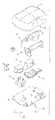
図1は、本発明の例示的な実施形態によるパッチポンプ1の例示的な実施形態の斜視図である。パッチポンプ1は、明瞭化のためにシースルーカバーを備えて示されており、パッチポンプ1を形成するべく組み立てられた様々な構成部品を示している。図2は、中実のカバー2を備えて示されている、図1のパッチポンプの様々な構成部品の分解図である。パッチポンプ1の様々な構成部品は、インスリンを貯蔵するためのリザーバ4、リザーバ4からインスリンをポンピングするためのポンプ3、1つ又は複数のバッテリーの形態の電源5、ユーザの皮膚にカテーテルを備えた挿入針を挿入する挿入機構7、スマートフォンを含む、遠隔制御装置及びコンピュータのような外部装置への任意の通信機能を有する回路基板の形態の制御電子機器8、急速静注用量を含むインスリン用量を作動させるためのカバー2の用量ボタン6、及び、上記の種々の構成部品が締結具91を介して取り付けられ得るベース9を含み得る。パッチポンプ1はまた、リザーバ4から汲出されたインスリンを注入部位に移送する様々な流体接続ラインを含んでいる。 FIG. 1 is a perspective view of an exemplary embodiment of patch pump 1 according to an exemplary embodiment of the present invention. The patch pump 1 is shown with a see-through cover for clarity and shows the various components assembled to form the patch pump 1. FIG. 2 is an exploded view of the various components of the patch pump of FIG. 1, which is shown with the solid cover 2. Various components of the patch pump 1 include a reservoir 4 for storing insulin, a
挿入機構は様々な構成であることを理解されたい。いくつかの実施形態では、挿入機構は、軟質カテーテルを皮膚に挿入する。これらの実施形態では、典型的には、軟質カテーテルが堅い挿入針に支持されている。挿入針は、軟質カテーテルとともに皮膚に挿入され、次いで、軟質カテーテルを皮膚内に残したまま皮膚から後退される。他の実施形態では、軟質カテーテルは提供されずに、挿入針が皮膚内に残り、注入が完了されるまで、インスリンを送達するためのインスリン流路の一部を形成する。挿入針は、典型的には中空であり、それらがインスリン流路の一部を形成する場合には、中空である必要がある。しかしながら、軟質カテーテルを支持し、次いで後退する挿入針は、中実又は中空のいずれであってもよい。挿入針が軟質カテーテルを展開させ、後退するが、インスリン流路の一部のまま残る場合には、挿入針は中空でなければならない。しかしながら、挿入針が軟質カテーテルを展開させ、次いで後退するが、インスリン流路の一部を形成しない場合には、挿入針は中実又は中空のいずれであってもよい。いずれの場合でも、挿入針は、好ましくは、皮膚を確実に貫通するのに十分な剛性を有するが、そうでなければ、ユーザに快適性を提供するのに十分な柔軟性を持たせるべく作られてもよい。 It should be understood that the insertion mechanism has various configurations. In some embodiments, the insertion mechanism inserts a soft catheter into the skin. In these embodiments, the soft catheter is typically supported by a rigid insertion needle. The insertion needle is inserted into the skin together with the soft catheter and then retracted from the skin leaving the soft catheter in the skin. In another embodiment, the soft catheter is not provided and the insertion needle remains in the skin, forming part of the insulin flow path for delivering insulin until the infusion is complete. Insertion needles are typically hollow and need to be hollow if they form part of the insulin flow path. However, the insertion needle that supports the soft catheter and then retracts may be solid or hollow. If the insertion needle unfolds and retracts the soft catheter, but remains part of the insulin flow path, the insertion needle must be hollow. However, the insertion needle may be solid or hollow if the insertion needle unfolds the soft catheter and then retracts, but does not form part of the insulin flow path. In either case, the insertion needle is preferably rigid enough to ensure that it penetrates the skin, but otherwise it is designed to be flexible enough to provide comfort to the user. May be
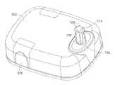
図3は、可撓性リザーバ4Aを有し、カバーなしで図示されたパッチポンプ1Aの別の設計の斜視図である。このような配置は、可撓性リザーバ4Aがパッチポンプ1A内の空隙を充填する状態で、パッチポンプ1Aの外形寸法をさらに減少させることができる。パッチポンプ1Aは、カニューレを、典型的には90度未満の鋭角でユーザの皮膚の表面に挿入する、従来のカニューレ挿入装置7Aを備えて示されている。パッチポンプ1Aは、バッテリーの形態の電源5A、インスリンの量を監視し、低容量検出能力を含有する計量サブシステム41、装置の構成部品を制御するための制御電子機器8A、及び、リザーバ4Aに充填する、補充注射器45を受け入れるリザーバ充填ポート43をさらに有している。 FIG. 3 is a perspective view of another design of patch pump 1A illustrated with a flexible reservoir 4A and without a cover. Such an arrangement can further reduce the external dimensions of the patch pump 1A while the flexible reservoir 4A fills the voids in the patch pump 1A. The patch pump 1A is shown with a conventional cannula insertion device 7A that inserts the cannula into the surface of the user's skin, typically at an acute angle of less than 90 degrees. The patch pump 1A includes a
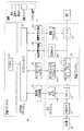
図4は、図3のパッチポンプ1Aのパッチポンプ流体構成及び計量サブシステムの略図である。パッチポンプ1Aの蓄電サブシステムは、バッテリー5Aを備えている。パッチポンプ1Aの制御電子機器8Aは、カニューレ挿入機構の作動を制御するマイクロコントローラ81、検知用電子機器82、ポンプ及びバルブコントローラ83、検知用電子機器85及び展開用電子機器87を含むことができる。パッチポンプ1Aは、リザーバ4Aと、リザーバ4Aの容量センサ48と、リザーバ4Aを補充するための補充注射器45を受入れるリザーバ充填ポート43とを備える流体サブシステムを含んでいる。流体サブシステムは、ポンプ及びバルブアクチュエータ411及び一体化されたポンプ及びバルブ機構413を備える計量システムを含むことができる。流体サブシステムは、閉塞センサ、展開アクチュエータのみならずユーザの皮膚上の注入部位への挿入のためのカニューレ47をさらに含むことができる。図1及び図2のパッチポンプのための構成は、図4に示されている装置と同じ又は類似している。 FIG. 4 is a schematic diagram of the patch pump fluid configuration and weighing subsystem of the patch pump 1A of FIG. The storage subsystem of the patch pump 1A includes a
本発明の実施形態は、パッチポンプのカテーテル挿入機構の誤った作動を防止し、ユーザがパッチポンプのリザーバに充填している間に、装置を安定化させるためのボタン安全キャップを含んでいる。本明細書に記載の実施形態は、特許文献1(PCT/US2015/027367)にさらに詳細に記載されている挿入機構を用いて動作するように特に適合されているが、当業者であれば、ボタン安全キャップの特定の構成を変更することによって、本発明の実施形態は、ボタンを有する任意の挿入機構で動作させるように適合させ得ることが理解されるべきである。本発明の実施形態は、剛性の針を使用して軟質のカニューレをユーザの皮膚に押し込み、次いで軟質のカニューレを皮膚に残して硬質の針を後退させるカニューレ挿入機構を有するパッチポンプと共に作用することができ、また、堅い留置針を使用する挿入機構と共に作用することもできる。 Embodiments of the invention include a button safety cap to prevent erroneous operation of the patch pump catheter insertion mechanism and to stabilize the device while the user fills the patch pump reservoir. The embodiments described herein are specifically adapted to operate with the insertion mechanism described in more detail in Patent Document 1 (PCT / US2015 / 027367), but those skilled in the art will appreciate it. It should be understood that by modifying the particular configuration of the button safety cap, embodiments of the present invention can be adapted to operate with any insertion mechanism having a button. Embodiments of the invention work with a patch pump having a cannula insertion mechanism that uses a rigid needle to push a soft cannula into the user's skin, then leaving the soft cannula on the skin and retracting the hard needle. It can also work with an insertion mechanism that uses a rigid indwelling needle.
誤った作動は針刺しの傷害を引き起こすことがあるので、そのような怪我を防止するボタン安全装置を提供することが望ましい。挿入機構が皮膚上に置かれる前に誤って作動される場合、カテーテル挿入機構がリセットできない場合には、パッチポンプはもはや使用できなくなる。誤った作動の前にリザーバが満たされていれば、インスリンもまた無駄になるであろう。ボタンの安全性がなければ、皮膚上に置かれる前に装置を操作している間に、ユーザが誤ってボタンを押すことによって、誤った起動が発生する可能性がある。特許文献1(PCT/US2015/027367)に記載の挿入機構は、少量の力が加えられたときに、薬剤送達装置の底部から針が露出することを防止する特徴を有するが、その閾値を超える力が誤って加えられた場合には、ユーザが導入針によって損傷されるかもしれない。図14及び15を参照するに、装置502が身体に接着される前に挿入機構起動ボタン514が完全に下まで押し下げられた場合には、カテーテル534は図15に示されるように遠位位置でロックし、そして導入針が引き込み、かくて、挿入機構を使用できなくする。ボタン514が、最小閾値力を超えるが、全ストローク長さ押されなかった場合には、導入針が露出されユーザをおそらく傷つけるが、針とカテーテルは装置内に後退する。このシナリオでは、挿入機構はリセットされ、カテーテルを皮膚に挿入するために使用され得るであろう。 Misoperation can cause needlestick injuries, so it is desirable to provide a button safety device to prevent such injuries. If the insertion mechanism is accidentally activated before it is placed on the skin, the patch pump can no longer be used if the catheter insertion mechanism cannot be reset. If the reservoir is filled before the misoperation, insulin will also be wasted. Without the safety of the button, the user could accidentally press the button while operating the device before it was placed on the skin, resulting in an erroneous activation. The insertion mechanism described in Patent Document 1 (PCT / US2015 / 027367) has a feature of preventing the needle from being exposed from the bottom of the drug delivery device when a small amount of force is applied, but exceeds the threshold value. If force is applied incorrectly, the user may be damaged by the introductory needle. Referring to FIGS. 14 and 15, if the insertion
挿入機構起動ボタン514は、リザーバの充填ステップ中に誤って作動され得る。図12及び図13を参照するに、リザーバ充填ポートは、挿入機構起動ボタン514に対し、典型的には、装置502の反対側に存する。ユーザは充填ポートの隔壁566に注射針を挿入し、注射器の内容物を注入して、装置502のリザーバを満たす。装置が充填ポートを上に向けて表面上に配置された場合には、ボタン安全キャップなしで、装置は挿入機構起動ボタン514の上に休止する。装置502が十分な力で下方に押されると、挿入機構が作動して図15に示されるように展開される。リザーバを満たすために注射器のプランジャを押すことは、これが発生することの原因となる。 The insertion
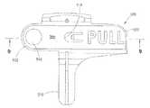
図5、6、7、8、9及び16は、本発明の例示的な実施形態によるボタン安全キャップ500を示している。図10、図11及び図12は、パッチポンプ502に取り付けられたボタン安全装置500を示している。パッチポンプ502は、好ましくは、ボタン安全キャップ500がパッチポンプ502に組み立てられた状態で製造される。パッチポンプ502に装着されると、ボタン安全キャップ500は、誤った作動を防止するべく、作動前の挿入機構起動ボタン514を覆っている。ボタン安全キャップ500は、必ずしも必要ではないが、プラスチックなどの剛性であるが可撓性の材料で構成された、単一の成形部品であることが好ましい。 5, 6, 7, 8, 9 and 16 show a
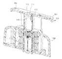
図示されているように、ボタン安全キャップ500は、ユーザがカテーテル挿入機構を(例えば、ボタン514を介して)作動させる準備ができているときに、ボタン安全キャップ500をパッチポンプから取り外すために、引っ張ることができる引張り部材504を含んでいる。ボタン安全キャップ500はまた、好ましくは、パッチポンプ502のハウジングにボタン安全キャップを安定化させるために輪郭表面506を含んでいる。図6、図9及び図10を参照するに、ボタン安全キャップ500の表面506は、ボタン安全キャップ500のポンプに対する安定性を高めるため、ポンプ502の側面、及びそれ故に、ボタン514の縦軸に平行なポンプの垂直軸に沿って形成されている。ボタン安全キャップ500はまた、ポンプ502に対するボタン安全キャップ500の安定性を高めるために、ポンプ502の横軸及び縦軸に沿ってそれぞれ配置されている安定化アーム508及び510を含んでもよい。 As shown, the
ボタン安全キャップ500の高さ寸法(例えば、ポンプの垂直軸に沿って延在するアーム508と引張り部材504の厚さとの組み合わせ寸法)は、図14に示されるような完全に展開前の位置にある挿入機構を収容するように構成されている。挿入機構は、その起動ボタン514が十分な力でトルクを受けると、損傷を受ける可能性がある。輪郭付けられた表面506と安定化アーム508及び510は、装置に損傷を与える又は挿入機構起動ボタン514にトルクをかける可能性のある方向への回転又は並進を防止するべく、パッチポンプ502上のボタン安全キャップ500を拘束している。 The height dimension of the button safety cap 500 (eg, the combined dimension of the
図8、図9及び図11を参照するに、引張り部材504はスナップ機構512を備える切欠き518を有している。スナップ機構512は、スナップ機構512にいくらかの可撓性を与えるために、切欠き518に部分的に渡って延在するように構成されている。図11に示されるように、スナップ機構512はまた、平行なポンプ502の垂直軸線及び挿入機構起動ボタン514の縦軸線にそれぞれ沿って、延在するように構成されている。スナップ機構512は、ボタン安全キャップ500をボタン514に保持するための張力を提供するが、ユーザがキャップ500をボタン514から取り外し、そして挿入機構を展開するべくボタン514を押すときに対応して、引張り部材504に指定された大きさの力が加えられると、キャップ500をボタン514から解放するために、ボタン514の表面又は縁部530と係合する角度付けられた表面を有している。 With reference to FIGS. 8, 9 and 11, the
図9は、スナップ機構512を示している、ボタン安全キャップ500の断面図である。図11は、パッチポンプ502に組み立てられているボタン安全キャップ500の断面図である。図11に示されるように、スナップ機構512は、挿入機構起動ボタン514の表面又は縁部530からスナップ機構512を係合解除するのに必要とされる所定の変形力に打ち勝つのに十分な力が使用されるまで、ボタン安全キャップ500を挿入機構起動ボタン514にロックしている。このようにして、ボタン安全装置500は、ユーザによって意図的に取り外されるまで、パッチポンプ502に保持される。スナップ機構512は、好ましくは、挿入機構への損傷を防ぐために、起動ボタン514の主軸の周りに過剰なトルクが加えられるとき、起動ボタン514から係合解除されるように設計される。 FIG. 9 is a cross-sectional view of the
挿入機構起動ボタン514の形状は、組み立てを容易にし、且つ、挿入機構起動ボタン514が展開する、装置502のハウジングの開口部532内での挿入機構起動ボタン514の回転を防止するために、図14、図15及び図16に示されるように、対向する平らな側部528を備えて構成されてもよい。加えて、ボタン安全キャップ500は、挿入機構を損傷させ組立をより困難にする回転運動無しで、ボタン安全キャップ500及びボタン514が組立てられるように、ボタン514の周囲に一致して対応する形状を有する空洞546を備えている。 The shape of the insertion
図8及び図16を参照するに、ボタン安全キャップ500の下面側は、その未展開位置(例えば、図14を参照)にあるときに、挿入機構起動ボタン514を受け入れるように寸法決めされた空洞546を有している。上述のように、挿入機構起動ボタン514は、対向する平坦な面又は側部528を有することができる。平坦面又は側部528の1つは、キャップ500がユーザによってボタン514から意図的に除去されるまで、ボタン安全キャップ500をボタン514に保持するべくスナップ機構512に係合する表面又は縁部530を含んでいる。ボタン安全キャップ500は、組み合わされた状態でボタンを拘束するために、ボタン514の平坦な面又は縁部528の他方に当接する対応する嵌合平坦面548を有している。 With reference to FIGS. 8 and 16, the underside of the
図6に戻るに、ボタン安全キャップ500の引張り部材504は、好ましくは、細長く、パッチポンプのハウジングの底部に位置されたリザーバポートに充填するべく、パッチポンプがユーザによって裏返されたときに、平坦な表面に接触する縁部516を含んでいる。縁部516は、リザーバ充填のために、表面上に逆さまに休止している間にパッチポンプを安定化させる。このようにして、ユーザに対するリザーバ充填がより容易に行われるのと同時に、ボタン安全装置500は、パッチポンプが裏返しされている間において、ユーザがパッチポンプを潜在的に押し下げている間における起動ボタン514の誤った起動を防止する。 Returning to FIG. 6, the
さらに、引張り部材504は、ボタン安全キャップ500の除去を便利にし、且つ効率的なユーザの動作でなすべく、ユーザの手の人間工学、特に、ユーザの手の親指及び指の作用を最適化するように、寸法及び形状付けられてもよい。図示のように、引張り部材504は、端部520及び522を有している。輪郭表面506の幅(すなわち、ポンプ502の横軸に沿った輪郭表面506の寸法)及びその端部520及び522に対する引張り部材504に沿った輪郭表面506の間隔は、ボタン514にトルクをかけることなく、キャップ500の把持のみならず持ち上げをも容易にすべく、例えば、一方の端部522においてユーザの右手の親指及び人差し指、及び他の端部520においてユーザの指球のうちの1つ以上に対応することができる。引張り部材 506の端部520及び522の寸法及び形状及び引張り部材504の表面領域は、挿入機構及び故にボタン安全キャップ500が薬剤送達装置(例えば、ポンプ502)のどこに配置されるかに応じて、異なるユーザの手及び指の人間工学に対応するように構成されてもよい。 In addition, the
様々な実施形態が図示され説明されてきたが、当業者には、添付の特許請求の範囲に定義された本発明の範囲から逸脱することなく変更を行うことができることが理解されよう。 Although various embodiments have been illustrated and described, those skilled in the art will appreciate that modifications can be made without departing from the scope of the invention as defined in the appended claims.
Claims (14)
Translated fromJapanese前記起動ボタンの周囲に一致して前記起動ボタンを受け入れるように構成された空洞、
ユーザの指に把持される2つの端部を有する引張り部材であって、一方の前記端部が、前記ユーザの第1指および第2指で挟持され、もう一方の前記端部が、少なくとも1以上の他の指の指球が接しながら持ち上げられる形状を有する引張り部材、
起動ボタンとボタン安全キャップが組立てられる薬剤送達装置との少なくとも1つに対しての当該ボタン安全キャップの回転及び/又は並進を防止するべく前記薬剤送達装置について延在するように適合されている少なくとも1つの安定化アーム、及び
当該起動ボタンに係合するべく適合されている可撓性のスナップ機構、を備え、
当該スナップ機構は、所定の除去力が当該ボタン安全キャップに加えられるまで、当該ボタン安全キャップを前記起動ボタン上に保持するように前記起動ボタンを係合することを特徴とするボタン安全キャップ。A button safety cap for the catheter insertion device of a drug delivery device comprising a housing and an activation button for the insertion mechanism so that the activation button for the insertion mechanism moves from an undeployed position with respect to the housing to a deployed position when pressed. Built in, the button safety cap,
A cavity, configured to match the circumference of the activation button and accept the activation button,
A pulling member having two ends gripped by a user's fingers, one said end being sandwiched between the user's first and second fingers and the other said end being at least one. A pulling member having a shape that can be lifted while touching the finger balls of the other fingers .
At least adapted to be extended with respect to the drug delivery device to prevent rotation and / or translation of the button safety cap with respect to at least one of the activation button and the drug delivery device from which the button safety cap is assembled. It has one stabilizing arm and a flexible snap mechanism adapted to engage the activation button.
The snap mechanism is a button safety cap that engages the activation button so as to hold the button safety cap onto the activation button until a predetermined removal force is applied to the button safety cap.
カニューレ挿入機構であって、前記流体注入装置のハウジングから延在する挿入機構の起動ボタンを備えるカニューレ挿入機構であって、前記挿入機構の起動ボタンは前記ハウジングに対する未展開位置から、押した際の展開位置に移動するように構築され、及び
当該起動ボタン上に組み立てられたボタン安全キャップであって、
前記起動ボタンの周囲に一致して前記起動ボタンを受け入れるように構成された空洞、
ユーザの指に把持される2つの端部を有する引張り部材であって一方の前記端部が、前記ユーザの第1指および第2指で挟持され、もう一方の前記端部が、少なくとも1以上の他の指の指球が接しながら持ち上げられる形状を有する引張り部材と、
前記起動ボタン及び前記流体注入装置の少なくとも一方に対するボタン安全キャップの回転及び/又は並進を防止するべく前記流体注入装置について延在するように適合された少なくとも1つの安定化アームと、
前記起動ボタンに係合するように適合された可撓性のスナップ機構と、を備えるボタン安全キャップを備え、
前記スナップ機構は、所定の除去力が前記ボタン安全キャップに加えられるまで、前記起動ボタン上に前記ボタン安全キャップを保持するように前記起動ボタンを係合することを特徴とする流体注入装置。It ’s a fluid injection device,
It is a cannula insertion mechanism, which is a cannula insertion mechanism including an activation button of an insertion mechanism extending from the housing of the fluid injection device, and the activation button of the insertion mechanism is when pressed from an undeployed position with respect to the housing. A button safety cap constructed to move to the unfolded position and assembled on the activation button.
A cavity, configured to match the circumference of the activation button and accept the activation button,
A pulling member having two ends gripped by a user's fingers, onesaid end being sandwiched between the user's first and second fingers, and the other end being at least one. A pulling member having a shape that can be lifted while touching the finger balls of other fingers ,
With at least one stabilizing arm adapted to extend for the fluid infusion device to prevent rotation and / or translation of the button safety cap with respect to at least one of the activation button and the fluid infusion device.
A button safety cap with a flexible snap mechanism adapted to engage the activation button,
The snap mechanism is a fluid injection device comprising engaging the activation button to hold the button safety cap on the activation button until a predetermined removal force is applied to the button safety cap.
Priority Applications (1)
| Application Number | Priority Date | Filing Date | Title |
|---|---|---|---|
| JP2021057464AJP7170775B2 (en) | 2015-04-24 | 2021-03-30 | Button safety cap for catheter insertion device |
Applications Claiming Priority (3)
| Application Number | Priority Date | Filing Date | Title |
|---|---|---|---|
| US201562152587P | 2015-04-24 | 2015-04-24 | |
| US62/152,587 | 2015-04-24 | ||
| PCT/US2016/028398WO2016172182A1 (en) | 2015-04-24 | 2016-04-20 | Button safety cap for catheter insertion device |
Related Child Applications (1)
| Application Number | Title | Priority Date | Filing Date |
|---|---|---|---|
| JP2021057464ADivisionJP7170775B2 (en) | 2015-04-24 | 2021-03-30 | Button safety cap for catheter insertion device |
Publications (2)
| Publication Number | Publication Date |
|---|---|
| JP2018512974A JP2018512974A (en) | 2018-05-24 |
| JP7061464B2true JP7061464B2 (en) | 2022-04-28 |
Family
ID=57144638
Family Applications (2)
| Application Number | Title | Priority Date | Filing Date |
|---|---|---|---|
| JP2017555560AActiveJP7061464B2 (en) | 2015-04-24 | 2016-04-20 | Button safety cap for catheter inserter |
| JP2021057464AActiveJP7170775B2 (en) | 2015-04-24 | 2021-03-30 | Button safety cap for catheter insertion device |
Family Applications After (1)
| Application Number | Title | Priority Date | Filing Date |
|---|---|---|---|
| JP2021057464AActiveJP7170775B2 (en) | 2015-04-24 | 2021-03-30 | Button safety cap for catheter insertion device |
Country Status (6)
| Country | Link |
|---|---|
| US (2) | US11285260B2 (en) |
| EP (1) | EP3285828B1 (en) |
| JP (2) | JP7061464B2 (en) |
| CN (1) | CN107614034B (en) |
| CA (1) | CA2982907A1 (en) |
| WO (1) | WO2016172182A1 (en) |
Families Citing this family (7)
| Publication number | Priority date | Publication date | Assignee | Title |
|---|---|---|---|---|
| TWI746569B (en) | 2016-06-08 | 2021-11-21 | 瑞士商瑞健醫療股份有限公司 | Dosiergerat, injektionsvorrichtung und verwendung |
| US11253652B2 (en) | 2016-11-28 | 2022-02-22 | Shl Medical Ag | Device for dispensing a substance |
| JP2020508803A (en)* | 2017-03-06 | 2020-03-26 | アムジエン・インコーポレーテツド | Drug delivery device with anti-actuation feature |
| CN119950880A (en) | 2017-05-05 | 2025-05-09 | 里珍纳龙药品有限公司 | Auto-injectors and related methods of use |
| CA3010640A1 (en)* | 2017-07-17 | 2019-01-17 | Becton Dickinson And Company | Delivery device with noise reducing component |
| US11602598B1 (en) | 2020-08-27 | 2023-03-14 | Fresenius Kabi Deutschland Gmbh | Prefilled syringe with pegfilgrastim having optimized dose and methods related thereto |
| USD1007676S1 (en) | 2021-11-16 | 2023-12-12 | Regeneron Pharmaceuticals, Inc. | Wearable autoinjector |
Citations (4)
| Publication number | Priority date | Publication date | Assignee | Title |
|---|---|---|---|---|
| JP2003158563A (en) | 2001-11-22 | 2003-05-30 | Nec Access Technica Ltd | Mobile terminal |
| CN201270215Y (en) | 2008-09-22 | 2009-07-08 | 蔡添庆 | Power switch protective cover |
| JP2013507230A (en) | 2009-10-13 | 2013-03-04 | バレリタス, インコーポレイテッド | Fluid delivery device |
| WO2015038850A2 (en) | 2013-09-12 | 2015-03-19 | Sio2 Medical Products, Inc. | Rapid, non-destructive, selective infrared spectrometry analysis of organic coatings on molded articles |
Family Cites Families (35)
| Publication number | Priority date | Publication date | Assignee | Title |
|---|---|---|---|---|
| US4484910A (en)* | 1983-12-21 | 1984-11-27 | Survival Technology, Inc. | Dual mode automatic injector |
| US5085641A (en)* | 1989-07-17 | 1992-02-04 | Survival Technology, Inc. | Conveniently carried frequent use auto-injector with improved cap structure |
| US5215534A (en)* | 1991-12-02 | 1993-06-01 | Lawrence De Harde | Safety syringe system |
| CN2132524Y (en)* | 1992-09-11 | 1993-05-12 | 刘杰 | Portable infusion pressurizer |
| US20070142776A9 (en)* | 1997-02-05 | 2007-06-21 | Medtronic Minimed, Inc. | Insertion device for an insertion set and method of using the same |
| WO1999030759A2 (en)* | 1997-12-16 | 1999-06-24 | Meridian Medical Technologies, Inc. | Automatic injector for administrating a medicament |
| AU2003228963B2 (en)* | 2002-05-10 | 2009-01-22 | Oriel Therapeutics, Inc. | Dry powder inhalers |
| US20030229308A1 (en)* | 2002-06-05 | 2003-12-11 | Israil Tsals | Injector adapter and combination thereof |
| CN100479875C (en)* | 2002-07-22 | 2009-04-22 | 贝克顿·迪金森公司 | Patch-like infusion device |
| CN1723053A (en)* | 2002-09-12 | 2006-01-18 | 儿童医院医疗中心 | Method and device for painless drug injection |
| EP3695862A1 (en)* | 2003-08-12 | 2020-08-19 | Becton, Dickinson and Company | Patch-like infusion device |
| US7097637B2 (en) | 2003-08-27 | 2006-08-29 | C. R. Bard, Inc. | Safety needle with positive flush |
| WO2005088661A1 (en)* | 2004-03-12 | 2005-09-22 | Nemoto Kyorindo Co., Ltd | Input operation device |
| ES2827179T3 (en)* | 2004-09-10 | 2021-05-20 | Becton Dickinson Co | Infusion reconstitution device |
| US7648483B2 (en)* | 2004-11-22 | 2010-01-19 | Intelliject, Inc. | Devices, systems and methods for medicament delivery |
| US9022980B2 (en)* | 2005-02-01 | 2015-05-05 | Kaleo, Inc. | Medical injector simulation device |
| US20070093760A1 (en)* | 2005-10-11 | 2007-04-26 | Wexler Michael R | Syringe with wound dressing material |
| CA2631435C (en)* | 2005-12-20 | 2014-08-12 | Antares Pharma, Inc. | Needle-free injection device |
| WO2007131013A1 (en)* | 2006-05-03 | 2007-11-15 | Antares Pharma, Inc. | Two-stage reconstituting injector |
| US9259535B2 (en)* | 2006-06-22 | 2016-02-16 | Excelsior Medical Corporation | Antiseptic cap equipped syringe |
| US20080228147A1 (en)* | 2007-03-15 | 2008-09-18 | Bristol-Myers Squibb Company | Injector for use with pre-filled syringes and method of assembly |
| EP3636301A1 (en)* | 2008-03-10 | 2020-04-15 | Antares Pharma, Inc. | Injector safety device |
| US8540673B2 (en)* | 2008-03-18 | 2013-09-24 | Calibra Medical, Inc. | Disposable infusion device with actuation lock-out |
| US9393369B2 (en)* | 2008-09-15 | 2016-07-19 | Medimop Medical Projects Ltd. | Stabilized pen injector |
| WO2011039213A2 (en)* | 2009-09-30 | 2011-04-07 | Sanofi-Aventis Deutschland Gmbh | An assembly of a drug delivery device |
| CN104307071B (en)* | 2009-12-16 | 2017-04-26 | 贝克顿·迪金森公司 | Self-injection device |
| US8070723B2 (en)* | 2009-12-31 | 2011-12-06 | Medtronic Minimed, Inc. | Activity guard |
| US20110160696A1 (en) | 2009-12-31 | 2011-06-30 | Abbott Diabetes Care Inc. | Injection port device adapted for use with insulin pump |
| US8998851B2 (en)* | 2011-02-09 | 2015-04-07 | Becton, Dickinson And Company | Compact spring inserter for drug deliver infusion set |
| EP2489387A1 (en)* | 2011-02-18 | 2012-08-22 | Sanofi-Aventis Deutschland GmbH | Auto-injector |
| CA2845379C (en)* | 2011-09-02 | 2019-08-06 | Unitract Syringe Pty Ltd | Insertion mechanism for a drug delivery pump |
| EP4186545A1 (en)* | 2012-04-06 | 2023-05-31 | Antares Pharma, Inc. | Needle assisted jet injection administration of testosterone compositions |
| US9522231B2 (en)* | 2012-04-13 | 2016-12-20 | Becton, Dickinson And Company | Infusion device with safety feature for preventing inadvertent activation |
| US9731069B2 (en)* | 2012-09-27 | 2017-08-15 | Becton, Dickinson And Company | Perpendicular infusion set and disposable inserter |
| US10293120B2 (en)* | 2015-04-10 | 2019-05-21 | West Pharma. Services IL, Ltd. | Redundant injection device status indication |
- 2016
- 2016-04-20JPJP2017555560Apatent/JP7061464B2/enactiveActive
- 2016-04-20CACA2982907Apatent/CA2982907A1/enactivePending
- 2016-04-20CNCN201680030885.7Apatent/CN107614034B/enactiveActive
- 2016-04-20USUS15/567,544patent/US11285260B2/enactiveActive
- 2016-04-20EPEP16783744.2Apatent/EP3285828B1/enactiveActive
- 2016-04-20WOPCT/US2016/028398patent/WO2016172182A1/ennot_activeCeased
- 2021
- 2021-03-30JPJP2021057464Apatent/JP7170775B2/enactiveActive
- 2022
- 2022-02-18USUS17/675,860patent/US12343497B2/enactiveActive
Patent Citations (4)
| Publication number | Priority date | Publication date | Assignee | Title |
|---|---|---|---|---|
| JP2003158563A (en) | 2001-11-22 | 2003-05-30 | Nec Access Technica Ltd | Mobile terminal |
| CN201270215Y (en) | 2008-09-22 | 2009-07-08 | 蔡添庆 | Power switch protective cover |
| JP2013507230A (en) | 2009-10-13 | 2013-03-04 | バレリタス, インコーポレイテッド | Fluid delivery device |
| WO2015038850A2 (en) | 2013-09-12 | 2015-03-19 | Sio2 Medical Products, Inc. | Rapid, non-destructive, selective infrared spectrometry analysis of organic coatings on molded articles |
Also Published As
| Publication number | Publication date |
|---|---|
| JP2018512974A (en) | 2018-05-24 |
| US20180099087A1 (en) | 2018-04-12 |
| US11285260B2 (en) | 2022-03-29 |
| EP3285828C0 (en) | 2024-10-30 |
| WO2016172182A1 (en) | 2016-10-27 |
| EP3285828A4 (en) | 2018-07-25 |
| JP7170775B2 (en) | 2022-11-14 |
| US12343497B2 (en) | 2025-07-01 |
| EP3285828A1 (en) | 2018-02-28 |
| CA2982907A1 (en) | 2016-10-27 |
| EP3285828B1 (en) | 2024-10-30 |
| CN107614034A (en) | 2018-01-19 |
| JP2021102091A (en) | 2021-07-15 |
| CN107614034B (en) | 2024-04-26 |
| US20220168501A1 (en) | 2022-06-02 |
Similar Documents
| Publication | Publication Date | Title |
|---|---|---|
| JP7170775B2 (en) | Button safety cap for catheter insertion device | |
| JP6581110B2 (en) | Catheter insertion mechanism for patch pump | |
| US10265466B2 (en) | Fluid infusion device | |
| JP6685236B2 (en) | Catheter insertion device | |
| EP3134148B1 (en) | Catheter insertion device | |
| CA2943686A1 (en) | Catheter insertion device | |
| US20230038182A1 (en) | User removable fill closure tab with integrated membrane | |
| US20240269433A1 (en) | Catheter insertion device and method of inserting a catheter |
Legal Events
| Date | Code | Title | Description |
|---|---|---|---|
| A621 | Written request for application examination | Free format text:JAPANESE INTERMEDIATE CODE: A621 Effective date:20190417 | |
| A977 | Report on retrieval | Free format text:JAPANESE INTERMEDIATE CODE: A971007 Effective date:20200228 | |
| A131 | Notification of reasons for refusal | Free format text:JAPANESE INTERMEDIATE CODE: A131 Effective date:20200310 | |
| A521 | Request for written amendment filed | Free format text:JAPANESE INTERMEDIATE CODE: A523 Effective date:20200610 | |
| A02 | Decision of refusal | Free format text:JAPANESE INTERMEDIATE CODE: A02 Effective date:20201201 | |
| A521 | Request for written amendment filed | Free format text:JAPANESE INTERMEDIATE CODE: A523 Effective date:20210330 | |
| C60 | Trial request (containing other claim documents, opposition documents) | Free format text:JAPANESE INTERMEDIATE CODE: C60 Effective date:20210330 | |
| A911 | Transfer to examiner for re-examination before appeal (zenchi) | Free format text:JAPANESE INTERMEDIATE CODE: A911 Effective date:20210406 | |
| C21 | Notice of transfer of a case for reconsideration by examiners before appeal proceedings | Free format text:JAPANESE INTERMEDIATE CODE: C21 Effective date:20210413 | |
| A912 | Re-examination (zenchi) completed and case transferred to appeal board | Free format text:JAPANESE INTERMEDIATE CODE: A912 Effective date:20210716 | |
| C211 | Notice of termination of reconsideration by examiners before appeal proceedings | Free format text:JAPANESE INTERMEDIATE CODE: C211 Effective date:20210720 | |
| C22 | Notice of designation (change) of administrative judge | Free format text:JAPANESE INTERMEDIATE CODE: C22 Effective date:20210914 | |
| C30 | Protocol of an oral hearing | Free format text:JAPANESE INTERMEDIATE CODE: C30 Effective date:20211027 | |
| C302 | Record of communication | Free format text:JAPANESE INTERMEDIATE CODE: C302 Effective date:20211028 | |
| C13 | Notice of reasons for refusal | Free format text:JAPANESE INTERMEDIATE CODE: C13 Effective date:20211109 | |
| A521 | Request for written amendment filed | Free format text:JAPANESE INTERMEDIATE CODE: A523 Effective date:20220209 | |
| C23 | Notice of termination of proceedings | Free format text:JAPANESE INTERMEDIATE CODE: C23 Effective date:20220301 | |
| C03 | Trial/appeal decision taken | Free format text:JAPANESE INTERMEDIATE CODE: C03 Effective date:20220405 | |
| C30A | Notification sent | Free format text:JAPANESE INTERMEDIATE CODE: C3012 Effective date:20220405 | |
| A61 | First payment of annual fees (during grant procedure) | Free format text:JAPANESE INTERMEDIATE CODE: A61 Effective date:20220418 | |
| R150 | Certificate of patent or registration of utility model | Ref document number:7061464 Country of ref document:JP Free format text:JAPANESE INTERMEDIATE CODE: R150 | |
| R250 | Receipt of annual fees | Free format text:JAPANESE INTERMEDIATE CODE: R250 |