JP7060958B2 - Video Stream Image Processing System and Method for Amplitude Modulated Light Flicker Correction - Google Patents
Video Stream Image Processing System and Method for Amplitude Modulated Light Flicker CorrectionDownload PDFInfo
- Publication number
- JP7060958B2 JP7060958B2JP2017566664AJP2017566664AJP7060958B2JP 7060958 B2JP7060958 B2JP 7060958B2JP 2017566664 AJP2017566664 AJP 2017566664AJP 2017566664 AJP2017566664 AJP 2017566664AJP 7060958 B2JP7060958 B2JP 7060958B2
- Authority
- JP
- Japan
- Prior art keywords
- flicker
- light source
- class
- video stream
- detected
- Prior art date
- Legal status (The legal status is an assumption and is not a legal conclusion. Google has not performed a legal analysis and makes no representation as to the accuracy of the status listed.)
- Active
Links
Images


Classifications
- H—ELECTRICITY
- H04—ELECTRIC COMMUNICATION TECHNIQUE
- H04N—PICTORIAL COMMUNICATION, e.g. TELEVISION
- H04N5/00—Details of television systems
- H04N5/44—Receiver circuitry for the reception of television signals according to analogue transmission standards
- H04N5/57—Control of contrast or brightness
- H04N5/58—Control of contrast or brightness in dependence upon ambient light
- G—PHYSICS
- G06—COMPUTING OR CALCULATING; COUNTING
- G06V—IMAGE OR VIDEO RECOGNITION OR UNDERSTANDING
- G06V20/00—Scenes; Scene-specific elements
- G06V20/50—Context or environment of the image
- G06V20/56—Context or environment of the image exterior to a vehicle by using sensors mounted on the vehicle
- G06V20/58—Recognition of moving objects or obstacles, e.g. vehicles or pedestrians; Recognition of traffic objects, e.g. traffic signs, traffic lights or roads
- G06V20/584—Recognition of moving objects or obstacles, e.g. vehicles or pedestrians; Recognition of traffic objects, e.g. traffic signs, traffic lights or roads of vehicle lights or traffic lights
- H—ELECTRICITY
- H04—ELECTRIC COMMUNICATION TECHNIQUE
- H04N—PICTORIAL COMMUNICATION, e.g. TELEVISION
- H04N23/00—Cameras or camera modules comprising electronic image sensors; Control thereof
- H04N23/70—Circuitry for compensating brightness variation in the scene
- H04N23/745—Detection of flicker frequency or suppression of flicker wherein the flicker is caused by illumination, e.g. due to fluorescent tube illumination or pulsed LED illumination
- B—PERFORMING OPERATIONS; TRANSPORTING
- B60—VEHICLES IN GENERAL
- B60R—VEHICLES, VEHICLE FITTINGS, OR VEHICLE PARTS, NOT OTHERWISE PROVIDED FOR
- B60R2300/00—Details of viewing arrangements using cameras and displays, specially adapted for use in a vehicle
- B60R2300/30—Details of viewing arrangements using cameras and displays, specially adapted for use in a vehicle characterised by the type of image processing
- B—PERFORMING OPERATIONS; TRANSPORTING
- B60—VEHICLES IN GENERAL
- B60R—VEHICLES, VEHICLE FITTINGS, OR VEHICLE PARTS, NOT OTHERWISE PROVIDED FOR
- B60R2300/00—Details of viewing arrangements using cameras and displays, specially adapted for use in a vehicle
- B60R2300/80—Details of viewing arrangements using cameras and displays, specially adapted for use in a vehicle characterised by the intended use of the viewing arrangement
- B60R2300/8046—Details of viewing arrangements using cameras and displays, specially adapted for use in a vehicle characterised by the intended use of the viewing arrangement for replacing a rear-view mirror system
Landscapes
- Engineering & Computer Science (AREA)
- Multimedia (AREA)
- Signal Processing (AREA)
- Physics & Mathematics (AREA)
- General Physics & Mathematics (AREA)
- Theoretical Computer Science (AREA)
- Studio Devices (AREA)
- Closed-Circuit Television Systems (AREA)
- Mechanical Engineering (AREA)
- Image Processing (AREA)
- Picture Signal Circuits (AREA)
Description
Translated fromJapanese本発明は概して表示装置にストリーミングされたビデオ画像の処理に関し、より具体的には、車両の外部の風景のビデオストリーム画像の処理に関する。一部の実施形態では、本発明はさらにより具体的には、車両内の後方を向いたカメラから取得される、バックミラーの代替として機能する表示装置にストリーミングされるビデオ画像の処理に関する。 The present invention generally relates to the processing of video images streamed to display devices, and more specifically to the processing of video stream images of landscapes outside the vehicle. In some embodiments, the invention more specifically relates to the processing of video images taken from a rear-viewing camera in a vehicle and streamed to a display device acting as an alternative to a rear-view mirror.
本発明の1つの態様によると、車両の後方の風景のビデオストリーム画像を供給するためのカメラを装備した車両のための表示システムが提供される。本表示システムは、ビデオストリーム画像を受信し、ビデオストリーム画像を処理するための画像処理ユニットと、処理されたビデオストリーム画像を表示するための表示装置とを備える。ビデオストリーム画像の処理を実行するために、画像処理ユニットは、ビデオストリーム画像中の振幅変調光源を検出し、検出した振幅変調光源を考え得るいくつかの分類のうちの1つに分類し、振幅変調光源の分類に基づいて、フリッカする振幅変調光源が検出されるビデオストリーム画像を選択し、そして、選択されたビデオストリーム画像中の任意の振幅変調光源のフリッカを補正するために、選択されたビデオストリーム画像を修正するよう構成される。 According to one aspect of the invention, there is provided a display system for a vehicle equipped with a camera for supplying a video stream image of the landscape behind the vehicle. The display system includes an image processing unit for receiving a video stream image and processing the video stream image, and a display device for displaying the processed video stream image. To perform the processing of a video stream image, the image processing unit detects the amplitude modulation light source in the video stream image, classifies the detected amplitude modulation light source into one of several possible classifications, and the amplitude. Based on the classification of the modulation light source, a video stream image in which the flicker amplitude modulation light source is detected is selected, and selected to correct the flicker of any amplitude modulation light source in the selected video stream image. Configured to modify the video stream image.
本発明の1つの態様によると、ビデオストリーム画像を受信し、ビデオストリーム画像を処理するための画像処理ユニットと、処理されたビデオストリーム画像を表示するための表示装置とを備える、表示システムが提供される。ビデオストリーム画像の処理を実行するために、画像処理ユニットは、ビデオストリーム画像中の振幅変調光源を検出し、検出された振幅変調光源を少なくとも2つのクラスに分類し、ここで、検出された振幅変調光源の第一のクラスは人が直接見たときに人によって知覚できないフリッカを有し、検出された振幅変調光源の第二のクラスは人が直接見たときに人によって知覚できるフリッカを有しており、ビデオストリーム画像の画像フレームを通して検出された振幅変調光源を追跡し、第一のクラスに分類される検出された振幅変調光源のそれぞれを表す画素を置換することで、第一のクラスに分類される振幅変調光源が検出されるビデオストリーム画像を、検出された振幅変調光源を表す画素が常に一定の状態にあるようにし、処理されたビデオストリーム画像が表示されるときに、第一のクラスに分類される検出された振幅変調光源のそれぞれが知覚できるフリッカを有しないように修正するよう構成される。 According to one aspect of the invention, there is provided a display system comprising an image processing unit for receiving a video stream image and processing the video stream image and a display device for displaying the processed video stream image. Will be done. To perform the processing of the video stream image, the image processing unit detects the amplitude-modulated light sources in the video stream image and classifies the detected amplitude-modulated light sources into at least two classes, where the detected amplitudes. The first class of modulated light sources have flicker that cannot be perceived by humans when viewed directly by humans, and the second class of detected amplitude modulated light sources have flicker that can be perceived by humans when viewed directly by humans. By tracking the amplitude-modulated light sources detected through the image frame of the video stream image and replacing the pixels representing each of the detected amplitude-modulated light sources classified in the first class, the first class A video stream image in which an amplitude-modulated light source classified as is detected, so that the pixels representing the detected amplitude-modulated light source are always in a constant state, and when the processed video stream image is displayed, the first Each of the detected amplitude-modulated light sources classified in the class of is configured to have no perceptible flicker.
本発明の1つの態様によると、ビデオストリーム画像中の振幅変調光源を検出すること、検出された振幅変調光源を少なくとも2つのクラスに分類すること、ここで、検出された振幅変調光源の第一のクラスは人が直接見たときに人によって知覚できないフリッカを有し、検出された振幅変調光源の第二のクラスは人が直接見たときに人によって知覚できるフリッカを有しており、ビデオストリーム画像の画像フレームを通して検出された振幅変調光源を追跡すること、さらに、第一のクラスに分類される検出された振幅変調光源のそれぞれを表す画素を置換することで、第一のクラスに分類される振幅変調光源が検出されるビデオストリーム画像を、検出された振幅変調光源を表す画素が常に一定の状態にあるようにし、処理されたビデオストリーム画像が表示されたときに、第一のクラスに分類される検出された振幅変調光源のそれぞれが知覚できるフリッカを有しないように修正すること、を含むビデオストリーム画像を処理する方法が提供される。 According to one aspect of the invention, detecting an amplitude-modulated light source in a video stream image, classifying the detected amplitude-modulated light source into at least two classes, where the first of the detected amplitude-modulated light sources. The second class of detected amplitude-modulated light sources has flicker that cannot be perceived by a person when viewed directly by a person, and the second class of detected amplitude-modulated light sources has flicker that can be perceived by a person when viewed directly by a person. Classified into first class by tracking the amplitude-modulated light sources detected through the image frame of the stream image and by replacing the pixels representing each of the detected amplitude-modulated light sources classified in the first class. The first class of video stream images in which the amplitude-modulated light source is detected is such that the pixels representing the detected amplitude-modulated light source are always in a constant state and the processed video stream image is displayed. A method of processing a video stream image is provided, including modifying each of the detected amplitude-modulated light sources classified into to have no perceptible flicker.
本発明のこれらおよびその他の特徴、利点、および目的は、以下の明細書、特許請求の範囲、および添付図面を参照することにより、当業者によってさらに理解および認識される。 These and other features, advantages, and purposes of the present invention will be further understood and recognized by those skilled in the art by reference to the following specification, claims, and accompanying drawings.
図面において、
ここでは本発明の好適実施態様を詳細に参照し、その例を添付図面に図示する。可能な限り、同一または類似した部品を参照するために、図面全体を通して同一の参照番号が使用される。図面では、描画された構造要素は原寸に比例しておらず、ある特定の構成要素は、強調および理解の目的で、その他の構成要素と比較して拡大されている。 Here, preferred embodiments of the present invention are referred to in detail, examples of which are illustrated in the accompanying drawings. Wherever possible, the same reference numbers are used throughout the drawing to refer to the same or similar parts. In the drawings, the drawn structural elements are not proportional to their actual size, and certain components are magnified compared to other components for emphasis and understanding purposes.
物体が撮像されるときに、撮像素子からキャプチャされるビデオストリーム画像のレンダリングにおいて生じる一般的な問題は、振幅変調光(AM)光源である。このタイプの光源の非常に一般的な例は、発光ダイオード(LED)で構成された車両ランプアセンブリのような、何らかの周期的なレートでパルスオン/オフする光源であり、この光源ではLEDがパルス幅変調(PWM)されるが、PWMは考え得る振幅変調方法のサブセットである。PWMの期間およびデューティサイクルにより、LEDが何らかの周期的レートでオンおよびオフし、このランプアセンブリのストリーミング画像を撮影するカメラが逐次画像をキャプチャするが、LEDは1つ以上の連続画像では「オン」であり、その後の1つ以上の画像では「オフ」であり得る。AM光源の他の例には、緊急車両上の回転灯(同じくPWM LEDから構成され得る)、車両上の方向指示灯、またはトンネルや駐車場における蛍光光源が挙げられる。 A common problem that arises in rendering a video stream image captured from an image pickup element when an object is imaged is an amplitude modulated light (AM) light source. A very common example of this type of light source is a light source that pulses on and off at some periodic rate, such as a vehicle lamp assembly composed of light emitting diodes (LEDs), in which the LED has a pulse width. Although modulated (PWM), PWM is a subset of possible amplitude modulation methods. The PWM period and duty cycle turn the LED on and off at some periodic rate, and the camera that captures the streaming image of this lamp assembly captures the sequential image, while the LED is "on" for one or more continuous images. And can be "off" in one or more subsequent images. Other examples of AM light sources include rotating lights on emergency vehicles (which may also consist of PWM LEDs), turn signal lights on vehicles, or fluorescent light sources in tunnels and parking lots.
上記でリストした例示的AM光源の多くについて、光源の人観察者は「オン/オフ」パターンのフリッカを知覚しないが、これは、オン/オフパターンの周波数が人の視覚システムが知覚できるよりも高いからである(PWM LEDヘッドランプ/テールランプアセンブリが典型的な例である)。しかし、AM光素子を電子カメラシステムで撮像する際、撮像素子アレイ中の特定の画素における光素子のキャプチャにおいて使用される露光時間、フレームレート、そしてシャッタ方式(ローリングまたはグローバル)により、この画素を示す一部の画像は光素子の「オン」状態を撮像し、この画素を示す逐次画像は光素子の「オフ」状態をキャプチャするすることとなり得る。何らかの表示フレームレートで、これらの画像を表示装置にレンダリングすることを企図する際に、表示システムが人観察者に「フリッカする」光として認識可能な「オン/オフ」パターンを示すこととなる場合がある。 For many of the exemplary AM light sources listed above, the human observer of the light source does not perceive the "on / off" pattern of flicker, which is more than the frequency of the on / off pattern can be perceived by the human visual system. Because it is expensive (a PWM LED headlamp / tail lamp assembly is a typical example). However, when an AM optical element is imaged by an electronic camera system, this pixel is captured by the exposure time, frame rate, and shutter method (rolling or global) used to capture the optical element at a particular pixel in the image sensor array. Some of the images shown may capture the "on" state of the light element, and the sequential images showing the pixels may capture the "off" state of the light element. When attempting to render these images to a display device at some display frame rate, the display system would show a human observer an "on / off" pattern that would be perceived as "flickering" light. There is.
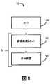
図1は、第一の実施形態による画像システム10を示す。図示されるように、画像システム10は、風景の画像をキャプチャし、風景のビデオストリーム画像を出力するカメラ26と、ビデオストリーム画像を受信し、画像を処理して(以下に詳細に説明するように)処理したビデオストリーム画像を出力する画像処理ユニット30および処理されたビデオストリーム画像を表示する表示装置32を含む表示システム12とを備える。 FIG. 1 shows an
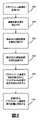
本明細書に記載の方法および処理シーケンスは、レンダリングされたAMヘッドランプおよびテールランプにおいて見受けられる「フリッカする」現象を軽減することを意図するものである(特にPWM LEDアセンブリを対象とするが、該技術の照明に限定されるものではない)。以下に記載するように、これらの方法が実装され得るプラットフォームは、自動車用ミラー代替システムの一部であり、車両ミラーは、カメラ(レンズとデジタル撮像素子)26、画像処理ユニット(シリアルプロセッサおよび/またはASIC/FPGA)30、および電子表示装置(LCD/LEDパネル)32で代替される。本明細書に記載の方法は、上記システム10中の画像処理ユニット30に組み込まれてもよい。図2に示されるように、本方法ステップは、以下のシーケンス(画像処理ユニット30上で生じ得るように)、1)ビデオストリーム画像を受信し(ステップ100)、2)連続するビデオストリーム画像におおけるPWM LED(またはAM)光の検出し(ステップ102)、3)PWM LED(またはAM)素子(ヘッドランプまたはテールランプアセンブリの一部である)を時変輝度レベルを有する風景における他の照明物体(例えば、緊急車両光)と区別/分類し(ステップ104)、4)経時でパルス光を追跡し(ステップ106)、5)これらのレンダリングされた光に関連付けられたフリッカアーチファクトを特定のタイプの光源に適切な方法で補正し(ステップ108)、および6)処理されたビデオストリーム画像を表示装置32に供給する(ステップ110)、で実行され得る。これらのステップのそれぞれに対して考え得る技術について以下に詳述する。 The methods and processing sequences described herein are intended to mitigate the "flickering" phenomenon seen in rendered AM headlamps and tail lamps (especially for PWM LED assemblies, but said. Not limited to technical lighting). As described below, the platforms on which these methods can be implemented are part of the automotive mirror replacement system, where the vehicle mirror is a camera (lens and digital imager) 26, an image processing unit (serial processor and /). Alternatively, it is replaced by an ASIC / FPGA) 30 and an electronic display device (LCD / LED panel) 32. The method described herein may be incorporated into the
キャプチャされた画像のシーケンスにおける時変光の検出を含むステップ102を実行するためには複数の方法が存在する。バックミラー代替システム(電子カメラ26、画像処理ユニット30および表示システム32に基づく)の問題領域において、検出する必要があり得るPWM LED光は、車両ヘッドランプおよびテールランプシステムから発生する光である。これらの光は、車両がミラー代替システムを備える場合の、同一の車道上にある車両に関連する。したがって、関心のPWM LED光に対する検索空間は車道検出による影響を受け得、オートエイムまたは車線検出システムが光検索空間を検出された道路境界上の垂直領域(車線検出システムより)、または消失点の周辺(オートエイムシステムより)に狭めることができ、静止非車両光源から識別される。この低減された探索空間では、権利者が共通する米国特許第6,587,573号、第6,593,698号、第6,611,610号、第6,631,316号、第6,653,614号、第6,728,393号、第6,774,988号、第6,861,809号、第6,906,467号、第6,947,577号、第7,321,112号、第7,417,221号、第7,565,006号、第7,567,291号、第7,653,215号、第7,683,326号、第7,881,839号、第8,045,760号、第8,120,652号および第8,543,254号に開示されるようなPWM LED光を検出するための既存のハイビーム制御システムにおける方法が存在する。 There are multiple ways to perform
また、フレーム減算等の検出方法を時変光源の検出のために使用してもよく、フレーム減算では、逐次画像が互いに減算されて時間差分マップを生成する。結果としてのマップはその後、ルーチン(ソフトウェアまたはASIC/FPGAファブリックに実装される)によって処理され、二値化および/またはフィルタリングの何らかの組み合わせを実行して、2つのソース画像間で画素輝度に大幅な変化があった、マップ中の空間領域を特定する。差分データの絶対値は、フレーム間の画素強度の変化の大きさを示し、差分データの標示はフレーム間の画素値の変化が光源が明るくなることに関連付けられているか、暗くなることに関連付けられているかを示す。これらの時間差分マップを生成するのに使用されるフレームデータは、べイヤーパターン画像からの生データ、画像から抽出された輝度データ、または画像処理経路から抽出された他の何らかの画像であり得る。一般的な車道風景において、一対のフレーム(単一の画素位置を参照する)間の画素値における最大デルタが、極度の明るさから完全なオフまであるこれらのPWM LED(AM)光に関連する傾向がある。モーションアーチファクトも、画素位置における画像値の時間変化に寄与し得るが、車両ダイナミックに比べて画像キャプチャレートが高速であり、固有の照明を生成しない物体に関連する輝度変化もかなり低減されるため(第一のフレームの画素において車両本体を、次のフレームで車両バンパーの一部を撮像することは、PWM LEDがそのオン/オフシーケンスで呈するほどの大幅な輝度変化を生じない)、車両によって撮像される車道の検索空間におけるこのモーションは非常に小さい。 Further, a detection method such as frame subtraction may be used for detecting a time-varying light source. In frame subtraction, successive images are subtracted from each other to generate a time difference map. The resulting map is then processed by a routine (software or implemented in an ASIC / FPGA fabric) to perform some combination of binarization and / or filtering to significantly reduce the pixel brightness between the two source images. Identify the spatial areas in the map that have changed. The absolute value of the difference data indicates the magnitude of the change in pixel intensity between frames, and the indication of the difference data is associated with the change in the pixel value between frames being associated with brightening or darkening of the light source. Show if it is. The frame data used to generate these time difference maps can be raw data from the Bayer pattern image, luminance data extracted from the image, or any other image extracted from the image processing path. In a typical roadway landscape, the maximum delta in pixel values between a pair of frames (referring to a single pixel position) is associated with these PWM LED (AM) lights ranging from extreme brightness to complete off. Tend. Motion artifacts can also contribute to time-varying changes in image values at pixel positions, but because image capture rates are faster than vehicle dynamics and luminance changes associated with objects that do not produce unique lighting are significantly reduced ( Imaging the vehicle body in the pixels of the first frame and part of the vehicle bumper in the next frame does not produce the significant change in brightness that the PWM LED exhibits in its on / off sequence), imaged by the vehicle. This motion in the search space of the roadway is very small.
AM光の存在を検出するための別の方法は、撮像素子実装を駆使するが、この場合、いくつかの撮像素子は、画素露光時間の間に風景の輝度が状態を変化させたか否かについての情報を(画素レベルに)提供し得る(特に、HDR CMOS撮像素子等の撮像素子について)。 Another method for detecting the presence of AM light makes full use of the image sensor mounting, but in this case, some image sensors determine whether the brightness of the landscape changed the state during the pixel exposure time. Information can be provided (at the pixel level) (especially for image sensors such as HDR CMOS image sensors).
以下に記載するように、パルス光を正確にレンダリングするための方法は、光が「オフ」としてキャプチャされる期間の間パルス光位置を「明るく」するために画像コンテンツを加えることと、光の時変性質によって引き起こされる不正確な色測定に対処することに該当しやすい。分類動作(ステップ104)が適用されて輝度および/または色誤差を導く時変光源のタイプを識別する。所望のパルス光だけ(例えば、モーションアーチファクトではない)が確実に補正されるように、光源分類が実行されて補正ステップ108に影響を与えてもよい。PWM LED光の分類方法は、権利者が共通する米国特許第6,587,573号、第6,593,698号、第6,611,610号、第6,631,316号、第6,653,614号、第6,728,393号、第6,774,988号、第6,861,809号、第6,906,467号、第6,947,577号、第7,321,112号、第7,417,221号、第7,565,006号、第7,567,291号、第7,653,215号、第7,683,326号、第7,881,839号、第8,045,760号、第8,120,652号および第8,543,254号に開示されるような、ハイビーム制御システムにおいて公知である。しかし、時間変化、色、輝度、および位置の使用における他のオプションも存在する。分類に輝度および色を使用するオプションは、カメラシステムにおけるべイヤーパターン、高ダイナミックレンジ(HDR)撮像素子の使用によって大きく向上するが、これは、明るい物体はHDR撮像素子では飽和されず、べイヤーパターン寄与分は非常に明るい光の色を判定するためにデモザイク処理することができるからである。車両を分類する物体検出システムを使用して、検索窓を特定された車両に関連付けられた領域に限定することで、PWM LEDヘッドランプ/テールランプの分類に影響を及ぼしてもよい。 As described below, the method for accurately rendering the pulsed light is to add image content to "brighten" the pulsed light position during the period when the light is captured as "off" and to add image content to the light. It tends to correspond to dealing with inaccurate color measurements caused by time-altered qualities. A classification operation (step 104) is applied to identify the type of time-varying light source that leads to luminance and / or color error. Light source classification may be performed to affect the
基本的に、この分類を用いて、光を直接見たときに人が知覚できるフリッカする光と、光を直接見たときにフリッカしているものと人が知覚できない光とを見分けることができる。このように、光源の画像がこうした分類に基づいて選択的に修正されて、光を直接見ている人に通常は見えるように表示風景内に光源が見えるようにし得る。 Basically, this classification can be used to distinguish between flicker light that a person can perceive when looking directly at light, and light that is flicker when looking directly at light and light that cannot be perceived by a person. .. In this way, the image of the light source can be selectively modified based on these classifications so that the light source is visible in the display landscape as it would normally be visible to a person looking directly at the light.
パルス光の時間追跡のステップ(ステップ106)は、権利者が共通する米国特許第6,587,573号、第6,593,698号、第6,611,610号、第6,631,316号、第6,653,614号、第6,728,393号、第6,774,988号、第6,861,809号、第6,906,467号、第6,947,577号、第7,321,112号、第7,417,221号、第7,565,006号、第7,567,291号、第7,653,215号、第7,683,326号、第7,881,839号、第8,045,760号、第8,120,652号、第8,543,254号および第9,185,363号に開示されるような公知のハイビーム制御システムにおいて記載される車両光追跡に対する技術を使用して実行することができる。時間および空間追跡は、修正された画像におけるフリッカする光源の所期の位置に対応する画素を明るくするために画像を選択的に修正する際に有用である。 The time tracking step of the pulsed light (step 106) includes US Pat. Nos. 6,587,573, 6,593,698, 6,611,610, 6,631,316, which are common to all rights holders. Nos. 6,653,614, 6,728,393, 6,774,988, 6,861,809, 6,906,467, 6,947,577, Nos. 7,321,112, 7,417,221, 7,565,006, 7,567,291, 7,653,215, 7,683,326,7 , 881,839, 8,045,760, 8,120,652, 8,543,254 and 9,185,363 in known high beam control systems. Can be performed using techniques for vehicle light tracking. Time and spatial tracking is useful in selectively modifying an image to brighten the pixels corresponding to the desired position of the flicker light source in the modified image.
ステップ108は、表示装置32上にレンダリングするために光フリッカを解消することを含む。表示装置フリッカ低減について対処する必要があるAM(またはパルス)光が特定されると、フリッカ低減のための本方法が、低画素値(「オフ」状態からの)を「オン」状態に関連付けられたレベルに対応する値と置換することで実行され得る。画素値置換は、生レベル(置換された画素に関連付けられたべイヤーパターンカラー)、または処理サブシステムにおける後の処理ステップにおいて実行することが可能である。ポストデモザイク処理ステップにおいて画素置換を実行するには利点があり、赤色、緑色、および青色寄与分の正確なバランスを生成することによってPWM光に対するカラーを維持することが可能である。画素置換が実行される際のAM光物体の表示された境界を維持するために、いくつかの画像処理ステップを用いて、ステップ106の追跡情報および物体形状検出ルーチンを用いて次のフレームの物体輪郭を予測することができる。 Step 108 includes eliminating optical flicker for rendering on the
あるいは、検出ステップからの時間差分マップを用いて、置換する画素の領域を画定することが可能であり(これらがフレーム間で状態が変化した画素を表すために)、2つだけのフレームの差分より多くを組み込むマップを用いることでより良好な結果が可能である。この方法の考え得る1つの実装は、フレームのシーケンスにわたる画素値の差分マップ(位置の)を生成し、最も高いM値の平均が何らかの閾値を上回る場合に、パルスPWM LED光の画像を生成していると判定された画素値をNフレームシーケンスにおける最も高いM値の平均と置換する(MはN未満)ことを含む。全体画像輝度および物体色の分析を使用する場合、この置換方法は、PWM LED検出、分類、追跡および置換の代わりとしても使用され得る。 Alternatively, a time difference map from the detection step can be used to define the area of the pixel to be replaced (to represent the pixel whose state has changed between frames) and the difference between only two frames. Better results are possible by using a map that incorporates more. One possible implementation of this method is to generate a pixel value difference map (of position) over a sequence of frames and generate an image of pulsed PWM LED light if the average of the highest M values exceeds some threshold. It includes replacing the pixel value determined to be with the average of the highest M values in the N frame sequence (M is less than N). When using global image brightness and object color analysis, this replacement method can also be used as an alternative to PWM LED detection, classification, tracking and replacement.
前向きの方向指示灯は、本明細書に開示の概念を用いて検出、分類および補正することができる時変光源の一例である。PWM光とは違って、その撮像素子上の行単位の値はビード周波数によって大きく変動し得、方向指示灯の周波数はカメラのフレームレートよりも大幅に低い(15~120Hzに対して1~2Hz)。これは、光の領域が方向指示灯の周波数でオンオフすることになる。光の境界内のこの空間的整合性は、方向指示灯および黄色みを示す検出された周波数と相まって、光を追跡された通りに方向指示灯として分類すること可能とし得る。システムが光の種類を分かると、システムはその黄色飽和を増大させることでこれを修正し、そのオン/オフ挙動はそのままで、より多くの視覚的アピールを生成することができる。 A forward-looking turn signal is an example of a time-varying light source that can be detected, classified and corrected using the concepts disclosed herein. Unlike PWM light, the row-by-row value on the image sensor can vary widely depending on the bead frequency, and the frequency of the turn signal is significantly lower than the frame rate of the camera (1-2 Hz relative to 15-120 Hz). ). This means that the area of light will be turned on and off at the frequency of the turn signal. This spatial integrity within the boundaries of the light, coupled with the turn signal and the detected frequency indicating yellowing, may allow the light to be classified as a turn signal as tracked. Once the system knows the type of light, the system can correct this by increasing its yellow saturation, leaving its on / off behavior intact and generating more visual appeal.
PWM LEDテールランプは、通常、背景に比べて相対的に明るくないため、正確に画像化および視覚化することが困難な物体である。また、ローリングシャッタカメラでは、画素の行それぞれがはっきりと異なるレベルの輝度を有する場合があり、そして、これはべイヤーフィルタの空間効果によって増大して、色度および輝度の両方における多くのアーチファクトにつながり得る。しかし、これらの行単位の変動、大きく異なる局所色、およびフレームごとに大幅に変化する色および強度等の特徴のいくつかと、画像中の位置、明るい赤色画素の支配、消失点に向かうモーション、光変調の周波数推定等のこの他の特徴により、これらの光を高精度に分類することが可能となり得る。PWM LEDテールランプの修正は、色を均一に飽和された赤色にすると同時に検出された範囲から輝度を選択することによって実行可能であり、これは視覚的にアピールし、不快なアーチファクトを除去することとなり得る。 PWM LED tail lamps are usually not as bright as the background, making it difficult to accurately image and visualize. Also, in rolling shutter cameras, each row of pixels may have distinctly different levels of brightness, which is increased by the spatial effect of the Bayer filter to many artifacts in both chromaticity and brightness. Can connect. However, some of these features such as row-by-line variation, very different local colors, and colors and intensities that change significantly from frame to frame, as well as position in the image, dominance of bright red pixels, motion towards the vanishing point, light. Other features, such as modulation frequency estimation, may allow these lights to be classified with high accuracy. Modification of the PWM LED tail lamp can be performed by making the color uniformly saturated red and at the same time selecting the brightness from the detected range, which will visually appeal and eliminate unpleasant artifacts. obtain.
次に図3を参照すると、上記実施形態の車両実装の概略図が示される。車両20は運転者22によって運転されるものとして示される。1つ以上のカメラ26は風景24が見えるよう動作する。図示する実施例において、風景24は概して車両20の後ろ側である。しかし、カメラ26は、限定されるものではないが、側部、背部、正面部、底部、上部、および内部を含む、車両20の周りの他の位置における風景を見るために種々の位置に方向付けられてもよい。図示する実施例において、風景を表す信号はチャネル28を介して画像処理ユニット30に送信される。画像処理ユニット30は、1つ以上の表示装置32上に風景24の向上した画像を生成する。随意の周辺光センサ34および1つ以上の直接グレアセンサ36からの入力も、画像処理ユニット30に利用可能である。 Next, with reference to FIG. 3, a schematic diagram of vehicle mounting of the above embodiment is shown. The
特定の有用な実施形態で、バックミラーアセンブリ50(図4A、図4B)は、後部および側部まで広域をカバーして、車両20のすぐ後ろの歩行者または他の物体が見え、かつ側部から接近する車が見えるようにする、カメラ26を有する画像化システム10によって増補または代替される。このシステムは、駐車場からバックして出るときに、走行車線に戻る前に接近する車両が見えるように設計される。このことは、ほぼ180度の視界を有するカメラシステム26、または車両の後部付近に取り付けられたいくつかのカメラシステム26を必要とする。車両20の正面付近に取り付けられたカメラまたは複数のカメラ26を有する類似のシステムは、対面交通の走行車線に入る前に、「見えない」交差点において対面交通を見るよう構成される。本発明について、従来的なバックミラーの表示機能を補完する、望ましい適用がある。 In certain useful embodiments, the rearview mirror assembly 50 (FIGS. 4A, 4B) covers a large area to the rear and sides so that pedestrians or other objects just behind the
図4Aおよび図4Bは、表示装置32と表示装置32の正面に位置付けられた随意のミラー素子52を備えた筐体54を有するバックミラーアセンブリ50の一例を示す。ユーザスイッチ56が、ミラー素子52および/または表示装置32を傾けて、作動時の表示装置32上のグレアを低減するために随意に提供されてもよい。こうしたバックミラーアセンブリ50の例は公知であり、権利者が共通する米国特許出願公報第2015/0219967A1号、第2015/0266427号A1号および第2015/0277203A1号に開示される。当該技術で公知のように、随意の周辺光センサ34および直接グレアセンサ36が、バックミラーアセンブリ50に組み込まれてもよい。さらに、画像処理ユニット30は、バックミラーアセンブリ50内に配置されてもよい。バックミラーアセンブリ50は、図4Aおよび図4Bに示されるように内部バックミラーアセンブリであってもよく、外部バックミラーアセンブリであってもよい。 4A and 4B show an example of a
上記の説明は、好適な実施形態についてのみのものと考えられる。当業者や本発明の製作者または使用者に対して、発明の変形が発生するであろう。従って、図面に示し上述した実施形態は、単に図示の目的のためであり、均等論を含む、特許法の原理に従い解釈されるものとして、特許請求によって定義される発明の範囲を制限する意図はないことが理解される。 The above description is considered only for preferred embodiments. Modifications of the invention will occur to those skilled in the art and the producers or users of the invention. Accordingly, the embodiments shown in the drawings and described above are for illustration purposes only and are intended to limit the scope of the invention as defined by the claims as being interpreted in accordance with the principles of patent law, including the doctrine of equivalents. It is understood that there is no.
Claims (8)
Translated fromJapanese前記ビデオストリーム画像を受信し、前記ビデオストリーム画像を処理するための画像処理ユニットと、
前記処理されたビデオストリーム画像を表示するための表示装置、とを備え、
前記ビデオストリーム画像の処理を実行するように、前記画像処理ユニットは、
前記ビデオストリーム画像におけるフリッカ光源を検出し、
前記検出されたフリッカ光源を第一のクラス及び第二のクラスを少なくとも含むいくつかの考え得る分類のうちの1つに分類し、
前記フリッカ光源の前記分類に基づいて、前記検出されたフリッカ光源を異なって処理するように構成され、
前記検出されたフリッカ光源の前記第一のクラスは、人が直接見たとき、人によって知覚できないフリッカを有し、検出されたフリッカ光源の前記第二のクラスは、人が直接見たとき、人によって知覚できるフリッカを有し、
前記処理は、
前記第一のクラスにあるフリッカ光源が検出される前記ビデオストリーム画像を選択し、そして、
前記選択されたビデオストリーム画像における前記第一のクラスの任意のフリッカ光源のフリッカを補正するよう前記選択されたビデオストリーム画像を修正することを含み、
前記画像処理ユニットは、前記第一のクラスに分類される前記検出されたフリッカ光源のそれぞれを表す画素がある状態に維持されて、前記処理されたビデオストリーム画像が表示されるとき、前記画素によって表される前記第一のクラスに分類される前記検出されたフリッカ光源のそれぞれが知覚できるフリッカを有さないように、前記選択されたビデオストリーム画像を修正し、
第一のクラスに分類される前記検出されたフリッカ光源のそれぞれは、オフ期間からの低画素値をオン期間からの高画素値と置換することで維持され、
前記第二のクラスに分類されるフリッカ光源は、方向指示灯及び緊急車両光を含み、前記画像処理ユニットは、方向指示灯または緊急車両光として分類されるフリッカ光源からのフリッカを補正するような前記ビデオストリーム画像の修正を行わず、
前記画像処理ユニットは、前記ビデオストリーム画像の画像フレームを通して前記検出されたフリッカ光源を追跡するようさらに構成され、
前記画像処理ユニットは、前記第一のクラスに分類される前記検出されたフリッカ光源のそれぞれを表す前記画素がある状態に維持されて、前記処理されたビデオストリーム画像が表示されたとき、前記画素によって表される前記第一のクラスに分類される前記検出されたフリッカ光源のそれぞれが、知覚できるフリッカを有しないように、かつ、前記第一のクラスに分類される前記検出されたフリッカ光源のそれぞれの前記追跡に基づいて前記ビデオストリーム画像における所期の位置に見えるように、前記選択されたビデオストリーム画像を修正する、表示システム。A display system for the vehicle equipped with a camera for supplying a video stream image of the landscape behind the vehicle.
An image processing unit for receiving the video stream image and processing the video stream image, and
A display device for displaying the processed video stream image, and
The image processing unit may perform processing of the video stream image.
Detecting the flicker light source in the video stream image,
The detected flicker light source is classified into one of several possible classifications including at least the first class and the second class.
Based on the classification of the flicker light source, the detected flicker light source is configured to be treated differently.
The first class of detected flicker light sources has flicker that cannot be perceived by a person when viewed directly by a person, and the second class of detected flicker light sources is when viewed directly by a person. Has flicker that can be perceived by humans
The above processing
Select the video stream image in which the flicker light source in the first class is detected, and
Including modifying the selected video stream image to correct the flicker of any flicker light source of the first class in the selected video stream image.
The image processing unit is maintained with pixels representing each of the detected flicker light sourcesclassified in the first class, and when the processed video stream image is displayed, the pixels. The selected video stream image is modified so that each of the detected flicker light sources representedin the first class has no perceptible flicker.
Each of the detected flicker sourcesclassified in the first class is maintained by replacing the low pixel value from the off period with the high pixel value from the on period.
The flicker light source classified into the second class includes a turn signal light and an emergency vehicle light, and the image processing unit corrects flicker from a flicker light source classified as a turn signal light or an emergency vehicle light.Without modifyingthe video stream image,
The image processing unit is further configured to track the detected flicker light source through an image frame of the video stream image.
The image processing unit is maintained with the pixels representing each of the detected flicker light sources classified in the first class, and when the processed video stream image is displayed, the pixels. Each of the detected flicker light sources classified into the first class represented by the above does not have perceptible flicker and the detected flicker light source classified into the first class. A display system that modifies the selected video stream image to appear at the desired position in the video stream image based on each said tracking .
ビデオストリーム画像を受信し、前記ビデオストリーム画像を処理するための画像処理ユニットと、
前記処理されたビデオストリーム画像を表示するための表示装置、とを備え、
前記ビデオストリーム画像の処理を実行するように、前記画像処理ユニットは、
前記ビデオストリーム画像におけるフリッカ光源を検出し、
前記検出されたフリッカ光源を少なくとも2つのクラスに分類し、検出されたフリッカ光源の第一のクラスは、人が直接見たときに人によって知覚できないフリッカを有し、検出されたフリッカ光源の第二のクラスは、人が直接見たときに人によって知覚できるフリッカを有しており、前記第二のクラスに分類されるフリッカ光源は、方向指示灯および緊急車両光を含み、
前記フリッカ光源の前記分類に基づいて、前記検出されたフリッカ光源を異なって処理するように構成され、当該処理は、
前記ビデオストリーム画像の画像フレームを通して前記検出されたフリッカ光源を追跡し、そして、
前記第一のクラスに分類されるフリッカ光源が検出される前記ビデオストリーム画像を、前記第一のクラスに分類される検出されたフリッカ光源のそれぞれを表す画素を置換することで、前記検出されたフリッカ光源を表す前記画素が常にある状態にあるようにし、前記処理されたビデオストリーム画像が表示されたとき、前記第一のクラスに分類される前記検出されたフリッカ光源のそれぞれが、知覚できるフリッカを有しないように修正すると共に、前記第一のクラスに分類される前記検出されたフリッカ光源のそれぞれの前記追跡に基づいて前記ビデオストリーム画像における所期の位置に見えるように修正し、前記第一のクラスに分類される前記検出されたフリッカ光源のそれぞれは、オフ期間からの低画素値をオン期間からの高画素値と置換することで維持され、
前記第二のクラスに分類されるフリッカ光源からのフリッカを補正するような前記ビデオストリーム画像の修正を行わないことを含む、表示システム。It's a display system
An image processing unit for receiving a video stream image and processing the video stream image,
A display device for displaying the processed video stream image, and
The image processing unit may perform processing of the video stream image.
Detecting the flicker light source in the video stream image,
The detected flicker light source is classified into at least two classes, and the first class of the detected flicker light source has flicker that cannot be perceived by the person when directly viewed by the person, and the detected flicker light source is the first class. The second class has flicker that can be perceived by a person when viewed directly, and the flicker light source classified into the second class includes a turn signal light and an emergency vehicle light.
Based on the classification of the flicker light source, the detected flicker light source is configured to be processed differently, and the processing is performed.
The detected flicker light source is tracked through the image frame of the video stream image, and
The video stream image in which the flicker light source classified in the first class is detected is detected by substituting the pixels representing each of the detected flicker light sources classified in the first class. The pixels representing the flicker light source are always in a certain state, and when the processed video stream image is displayed, each of the detected flicker light sources classified into the first class is a perceptible flicker. And sothat it looks like the desired position in the video stream image based on the tracking of each of the detected flicker light sources classified in the first class. Each of the detected flicker sourcesclassified into one class is maintained by replacing the low pixel value from the off period with the high pixel value from the on period.
A display system comprisingnot modifyingthe video stream image tocorrect for flicker from the flicker light source classified in the second class.
前記ビデオストリーム画像におけるフリッカ光源を検出し、
前記検出されたフリッカ光源を少なくとも2つのクラスに分類し、検出されたフリッカ光源の第一のクラスは人が直接見たときに人によって知覚できないフリッカを有し、検出されたフリッカ光源の第二のクラスは人が直接見たときに人によって知覚できるフリッカを有しており、前記第二のクラスに分類されるフリッカ光源は、方向指示灯および緊急車両光を含み、
前記フリッカ光源の前記分類に基づいて、前記検出されたフリッカ光源を異なって処理することを含み、当該処理は、
前記ビデオストリーム画像の画像フレームを通して前記検出されたフリッカ光源を追跡し、そして、
前記第一のクラスに分類されるフリッカ光源が検出されるビデオストリーム画像を、前記第一のクラスに分類される前記検出されたフリッカ光源のそれぞれを表す画素を置換することで、前記検出されたフリッカ光源を表す画素が常にある状態にあるようにし、前記処理されたビデオストリーム画像が表示されたとき、前記第一のクラスに分類される前記検出されたフリッカ光源のそれぞれが、知覚できるフリッカを有しないように修正すると共に前記第一のクラスに分類される前記検出されたフリッカ光源のそれぞれの前記追跡に基づいて前記ビデオストリーム画像における所期の位置に見えるように修正し、
フリッカについて前記第二のクラスに分類されるフリッカ光源を補正しないことを含む、方法。A way to process video stream images
Detecting the flicker light source in the video stream image,
The detected flicker light source is classified into at least two classes, and the first class of detected flicker light sources has flicker that cannot be perceived by a person when directly viewed by a person, and the second of the detected flicker light sources. Classes have flicker that can be perceived by a person when viewed directly, and the flicker light sources classified in the second class include turn signal lights and emergency vehicle lights.
The processing comprises treating the detected flicker light source differently based on the classification of the flicker light source.
The detected flicker light source is tracked through the image frame of the video stream image, and
The detected video stream image in which the flicker light source classified into the first class is detected by replacing the pixels representing each of the detected flicker light sources classified in the first class. Make sure that the pixels representing the flicker light source are always present, and when the processed video stream image is displayed, each of the detected flicker light sources classified into the first class will perceive flicker. Corrected to not have and modifiedto appear in the desired position in the video stream image based on the tracking of each of the detected flicker light sources classified in the first class .
A method comprising not correcting a flicker light source classified in the second class for flicker.
Priority Applications (1)
| Application Number | Priority Date | Filing Date | Title |
|---|---|---|---|
| JP2020160838AJP7296350B2 (en) | 2015-06-22 | 2020-09-25 | Video stream image processing system and method for flicker correction of amplitude modulated light |
Applications Claiming Priority (3)
| Application Number | Priority Date | Filing Date | Title |
|---|---|---|---|
| US201562182863P | 2015-06-22 | 2015-06-22 | |
| US62/182,863 | 2015-06-22 | ||
| PCT/US2016/038639WO2016209877A1 (en) | 2015-06-22 | 2016-06-22 | System and method for processing streamed video images to correct for flicker of amplitude-modulated lights |
Related Child Applications (1)
| Application Number | Title | Priority Date | Filing Date |
|---|---|---|---|
| JP2020160838ADivisionJP7296350B2 (en) | 2015-06-22 | 2020-09-25 | Video stream image processing system and method for flicker correction of amplitude modulated light |
Publications (2)
| Publication Number | Publication Date |
|---|---|
| JP2018526851A JP2018526851A (en) | 2018-09-13 |
| JP7060958B2true JP7060958B2 (en) | 2022-04-27 |
Family
ID=57586511
Family Applications (2)
| Application Number | Title | Priority Date | Filing Date |
|---|---|---|---|
| JP2017566664AActiveJP7060958B2 (en) | 2015-06-22 | 2016-06-22 | Video Stream Image Processing System and Method for Amplitude Modulated Light Flicker Correction |
| JP2020160838AActiveJP7296350B2 (en) | 2015-06-22 | 2020-09-25 | Video stream image processing system and method for flicker correction of amplitude modulated light |
Family Applications After (1)
| Application Number | Title | Priority Date | Filing Date |
|---|---|---|---|
| JP2020160838AActiveJP7296350B2 (en) | 2015-06-22 | 2020-09-25 | Video stream image processing system and method for flicker correction of amplitude modulated light |
Country Status (6)
| Country | Link |
|---|---|
| US (1) | US11178353B2 (en) |
| EP (1) | EP3310618B1 (en) |
| JP (2) | JP7060958B2 (en) |
| KR (1) | KR102135427B1 (en) |
| CN (1) | CN107709096B (en) |
| WO (1) | WO2016209877A1 (en) |
Families Citing this family (15)
| Publication number | Priority date | Publication date | Assignee | Title |
|---|---|---|---|---|
| EP3292024A4 (en)* | 2015-05-06 | 2018-06-20 | Magna Mirrors of America, Inc. | Vehicle vision system with blind zone display and alert system |
| WO2019025318A1 (en) | 2017-08-04 | 2019-02-07 | Smr Patents Sarl | Modulation control method for a filter device, electro- or magneto-optic modulated anti-flicker filter device, camera system with such a filter device, and a rear view device with such a camera system |
| CN108470362A (en)* | 2018-01-29 | 2018-08-31 | 北京奇虎科技有限公司 | A kind of method and apparatus for realizing video toning |
| WO2020090512A1 (en)* | 2018-10-31 | 2020-05-07 | ソニー株式会社 | Imaging device, control method, and program |
| US11019277B2 (en)* | 2018-11-30 | 2021-05-25 | Omnivision Technologies, Inc. | LED flicker reduction for high dynamic range imaging |
| US10944912B2 (en)* | 2019-06-04 | 2021-03-09 | Ford Global Technologies, Llc | Systems and methods for reducing flicker artifacts in imaged light sources |
| EP3983841B1 (en) | 2019-06-13 | 2023-09-20 | Gentex Corporation | Switchable multi-view imaging system |
| US12200369B2 (en) | 2019-09-03 | 2025-01-14 | Jaguar Land Rover Limited | Method and system for mitigating image flicker from strobed lighting systems |
| US10863106B1 (en)* | 2019-10-21 | 2020-12-08 | GM Global Technology Operations LLC | Systems and methods for LED flickering and banding detection |
| US11531145B2 (en) | 2020-03-09 | 2022-12-20 | Motherson Innovations Company Limited | Device for an image acquisition system |
| CN115769250A (en)* | 2020-07-15 | 2023-03-07 | 安致尔软件公司 | Vision Systems for Motor Vehicles |
| US11490023B2 (en) | 2020-10-30 | 2022-11-01 | Ford Global Technologies, Llc | Systems and methods for mitigating light-emitting diode (LED) imaging artifacts in an imaging system of a vehicle |
| US12394199B2 (en)* | 2021-07-08 | 2025-08-19 | Garmin International, Inc. | Enhanced flight vision system |
| WO2024119511A1 (en)* | 2022-12-09 | 2024-06-13 | Guangdong Oppo Mobile Telecommunications Corp., Ltd. | Image processing device, method, and program |
| US12394395B2 (en)* | 2023-07-13 | 2025-08-19 | GM Global Technology Operations LLC | Vehicle systems and methods for environmental camera view display adaptation |
Citations (3)
| Publication number | Priority date | Publication date | Assignee | Title |
|---|---|---|---|---|
| JP2008211442A (en) | 2007-02-26 | 2008-09-11 | Shinano Kenshi Co Ltd | Drive recorder |
| JP2009214795A (en) | 2008-03-12 | 2009-09-24 | Nissan Motor Co Ltd | Onboard image presenting device and method |
| JP2013216286A (en) | 2012-04-12 | 2013-10-24 | Suzuki Motor Corp | Monitoring device for confirming vehicle surroundings |
Family Cites Families (434)
| Publication number | Priority date | Publication date | Assignee | Title |
|---|---|---|---|---|
| US2131888A (en) | 1933-11-06 | 1938-10-04 | Floyd M Harris | Automobile lighting system |
| US2632040A (en) | 1952-05-01 | 1953-03-17 | Rabinow Jacob | Automatic headlight dimmer |
| US2827594A (en) | 1954-09-02 | 1958-03-18 | Rabinow Jacob | Color discriminating headlight dimmer |
| US3179845A (en) | 1961-05-01 | 1965-04-20 | Kulwiec Chester | Headlight illumination and signaling system for motor vehicles |
| US3581276A (en) | 1968-03-22 | 1971-05-25 | Essex International Inc | Vehicle light control and warning indicator system |
| US3663819A (en) | 1969-07-23 | 1972-05-16 | Lucas Industries Ltd | Road vehicle lighting system in which same shutter obscures photocell when system is operative and when it is not energized |
| US4109235A (en) | 1971-10-29 | 1978-08-22 | Regie Nationale Des Usines Renault | Electronic-display instrument panels for automotive vehicles |
| JPS5844228B2 (en) | 1976-07-08 | 1983-10-01 | トヨタ自動車株式会社 | Obstacle detection radar for vehicles |
| US4139801A (en) | 1977-01-26 | 1979-02-13 | Linares Raul F | Automatic automobile light control system |
| FR2426881A1 (en) | 1978-05-22 | 1979-12-21 | Dassault Avions | SIGHTING DEVICE FOR REAR FIRE ON COMBAT AIRCRAFT |
| US4214266A (en) | 1978-06-19 | 1980-07-22 | Myers Charles H | Rear viewing system for vehicles |
| US4277804A (en) | 1978-11-01 | 1981-07-07 | Elburn Robison | System for viewing the area rearwardly of a vehicle |
| US4258979A (en) | 1978-12-08 | 1981-03-31 | Mahin William E | Rear view mirror assembly |
| US4236099A (en) | 1979-03-05 | 1980-11-25 | Irving Rosenblum | Automatic headlight system |
| US4257703A (en) | 1979-03-15 | 1981-03-24 | The Bendix Corporation | Collision avoidance using optical pattern growth rate |
| US4376909A (en) | 1979-04-13 | 1983-03-15 | Honda Giken Kogyo Kabushiki Kaisha | Automatic light control for automotive vehicles |
| US4286308A (en) | 1979-09-04 | 1981-08-25 | Polaroid Corporation | Apparatus and method for reducing headlight glare |
| FR2492748A2 (en) | 1979-11-07 | 1982-04-30 | Massoni Francois | DEVICE FOR AUTOMATICALLY CONTROLLING IGNITION AND EXTINGUISHING LIGHTS IN A VEHICLE |
| GB2099628B (en) | 1981-04-07 | 1984-11-14 | Nippon Denso Co | Electroluminescent device combined with mirror |
| US6442465B2 (en) | 1992-05-05 | 2002-08-27 | Automotive Technologies International, Inc. | Vehicular component control systems and methods |
| US5845000A (en) | 1992-05-05 | 1998-12-01 | Automotive Technologies International, Inc. | Optical identification and monitoring system using pattern recognition for use with vehicles |
| US6772057B2 (en) | 1995-06-07 | 2004-08-03 | Automotive Technologies International, Inc. | Vehicular monitoring systems using image processing |
| US6507779B2 (en) | 1995-06-07 | 2003-01-14 | Automotive Technologies International, Inc. | Vehicle rear seat monitor |
| US4638287A (en) | 1983-03-01 | 1987-01-20 | Aisin Seiki Kabushikikaisha | Vehicle-loaded display device |
| US4479173A (en) | 1983-04-21 | 1984-10-23 | Rumpakis George E | Lighted instrument assembly |
| US4692798A (en) | 1984-01-09 | 1987-09-08 | Nissan Motor Company, Limited | Apparatus and process for improving visibility of object within visual field |
| US4665430A (en) | 1984-01-20 | 1987-05-12 | Matsushita Electric Industrial Co., Ltd | Monitoring apparatus |
| US4599544A (en) | 1984-05-24 | 1986-07-08 | General Motors Corporation | Vehicle headlamp beam control |
| JPS60256076A (en) | 1984-06-01 | 1985-12-17 | Nissan Motor Co Ltd | Apparatus for detecting preceding car |
| US4645975A (en) | 1984-09-04 | 1987-02-24 | Ford Motor Company | Composite light pickup device |
| US4891559A (en) | 1985-06-13 | 1990-01-02 | Nippondenso Soken, Inc. | Apparatus for controlling a headlight of a vehicle |
| US4665321A (en) | 1985-08-14 | 1987-05-12 | Kwangling Chang | Automatic control system for automobile lights |
| JPS62132488A (en) | 1985-12-04 | 1987-06-15 | Aisin Seiki Co Ltd | On-vehicle display device |
| DE3601388A1 (en) | 1986-01-18 | 1987-07-23 | Bosch Gmbh Robert | HEADLIGHT SYSTEM FOR VEHICLES, ESPECIALLY FOR MOTOR VEHICLES |
| US5005213A (en) | 1986-07-10 | 1991-04-02 | Varo, Inc. | Head mounted video display and remote camera system |
| US4727290A (en) | 1987-05-29 | 1988-02-23 | General Motors Corporation | Automatic vehicle headlamp dimming control |
| JPH01158579A (en) | 1987-09-09 | 1989-06-21 | Aisin Seiki Co Ltd | Image recognizing device |
| US4862037A (en) | 1987-12-24 | 1989-08-29 | Ford Motor Company | Automatic headlamp dimming system |
| US4930742A (en) | 1988-03-25 | 1990-06-05 | Donnelly Corporation | Rearview mirror and accessory mount for vehicles |
| JPH01278848A (en) | 1988-05-02 | 1989-11-09 | Nissan Motor Co Ltd | Vehicle headlight device |
| US4910591A (en) | 1988-08-08 | 1990-03-20 | Edward Petrossian | Side and rear viewing apparatus for motor vehicles |
| CA1329263C (en) | 1989-03-01 | 1994-05-03 | Mark Krichever | Bar code scanner |
| US4934273A (en) | 1989-06-20 | 1990-06-19 | Spectra Diode Laboratories, Inc. | Laser flare |
| US5303205A (en) | 1990-02-26 | 1994-04-12 | Trend Tec Inc. | Vehicular distance measuring system with integral mirror display |
| US5355146A (en) | 1990-03-05 | 1994-10-11 | Bmc Micro-Industries Ltd. | Multi-directional hand scanner and mouse |
| US5072154A (en) | 1990-03-13 | 1991-12-10 | Chen Min Hsiung | Automatic luminosity control device for car and motor bicycle headlamps |
| JP2920653B2 (en) | 1990-03-15 | 1999-07-19 | アイシン精機株式会社 | In-vehicle imaging device |
| JPH0412144A (en) | 1990-04-28 | 1992-01-16 | Aisin Seiki Co Ltd | Vehicle speed control device |
| JP3043469B2 (en) | 1990-07-05 | 2000-05-22 | キヤノン株式会社 | Large-capacity color laser printing system |
| US5121200A (en) | 1990-07-06 | 1992-06-09 | Choi Seung Lyul | Travelling monitoring system for motor vehicles |
| US5027200A (en) | 1990-07-10 | 1991-06-25 | Edward Petrossian | Enhanced viewing at side and rear of motor vehicles |
| US5166681A (en) | 1990-07-30 | 1992-11-24 | Bottesch H Werner | Passive vehicle presence detection system |
| US5036437A (en) | 1990-09-04 | 1991-07-30 | Lectron Products, Inc. | Vehicle lamp control sensor |
| US5905457A (en) | 1990-10-11 | 1999-05-18 | Rashid; Charles | Vehicle radar safety apparatus |
| US5124549A (en) | 1990-10-15 | 1992-06-23 | Lectron Products, Inc. | Automatic headlamp dimmer with optical baffle |
| US5086253A (en) | 1990-10-15 | 1992-02-04 | Lawler Louis N | Automatic headlight dimmer apparatus |
| US5187383A (en) | 1990-11-06 | 1993-02-16 | Alfonse Taccetta | Headlight actuator associated with windsheild wiper actuation having delay circuits and daylight detection |
| JP2987778B2 (en) | 1990-11-30 | 1999-12-06 | アイシン精機株式会社 | Vehicle speed control device |
| JPH04331311A (en) | 1991-01-24 | 1992-11-19 | Mitsubishi Electric Corp | Detecting apparatus of inter-vehicle distance |
| US5451822A (en) | 1991-03-15 | 1995-09-19 | Gentex Corporation | Electronic control system |
| US5182502A (en) | 1991-05-06 | 1993-01-26 | Lectron Products, Inc. | Automatic headlamp dimmer |
| FR2676284B1 (en) | 1991-05-07 | 1994-12-02 | Peugeot | METHOD FOR DETECTING OBSTACLES PRESENT IN FRONT OF A MOTOR VEHICLE AND DEVICE FOR CARRYING OUT SUCH A METHOD. |
| JPH05319174A (en) | 1991-05-17 | 1993-12-03 | Mutsurou Buntou | Visibility display device for automobile |
| US5469298A (en) | 1991-08-14 | 1995-11-21 | Prince Corporation | Reflective display at infinity |
| JP3110095B2 (en) | 1991-09-20 | 2000-11-20 | 富士通株式会社 | Distance measuring method and distance measuring device |
| US5416318A (en) | 1991-10-03 | 1995-05-16 | Hegyi; Dennis J. | Combined headlamp and climate control sensor having a light diffuser and a light modulator |
| US5235178A (en) | 1991-10-03 | 1993-08-10 | Hegyi Dennis J | Light sensor with diffuser and eye-like response |
| JP3031013B2 (en) | 1991-11-15 | 2000-04-10 | 日産自動車株式会社 | Visual information providing device |
| US5402170A (en) | 1991-12-11 | 1995-03-28 | Eastman Kodak Company | Hand-manipulated electronic camera tethered to a personal computer |
| US5576687A (en) | 1991-12-20 | 1996-11-19 | Donnelly Corporation | Vehicle information display |
| JP2800531B2 (en) | 1992-02-28 | 1998-09-21 | 三菱電機株式会社 | Obstacle detection device for vehicles |
| US5243417A (en) | 1992-03-05 | 1993-09-07 | Sony Corporation | Rear vision system for two-wheeled vehicles with movable handlebars |
| US5523811A (en) | 1992-04-17 | 1996-06-04 | Canon Kabushiki Kaisha | Camera device for moving body |
| JP3183966B2 (en) | 1992-04-20 | 2001-07-09 | マツダ株式会社 | Vehicle travel control device |
| GB2267341B (en) | 1992-05-27 | 1996-02-21 | Koito Mfg Co Ltd | Glare sensor for a vehicle |
| US5515448A (en) | 1992-07-28 | 1996-05-07 | Yazaki Corporation | Distance measuring apparatus of a target tracking type |
| JPH0785280B2 (en) | 1992-08-04 | 1995-09-13 | タカタ株式会社 | Collision prediction judgment system by neural network |
| JP2783079B2 (en) | 1992-08-28 | 1998-08-06 | トヨタ自動車株式会社 | Light distribution control device for headlamp |
| JP3158707B2 (en) | 1992-09-09 | 2001-04-23 | 株式会社デンソー | Optical radar equipment for vehicles |
| US5408357A (en) | 1992-11-09 | 1995-04-18 | Prince Corporation | Display depolarizer |
| US5475441A (en) | 1992-12-10 | 1995-12-12 | Eastman Kodak Company | Electronic camera with memory card interface to a computer |
| JP3263699B2 (en) | 1992-12-22 | 2002-03-04 | 三菱電機株式会社 | Driving environment monitoring device |
| US5347261A (en) | 1993-01-21 | 1994-09-13 | Robert Adell | "Hands free" vehicle bright light signal system |
| JPH06286521A (en) | 1993-02-10 | 1994-10-11 | Ford Motor Co | Method and device for automatic shifting of car head light to low beam |
| US5289321A (en) | 1993-02-12 | 1994-02-22 | Secor James O | Consolidated rear view camera and display system for motor vehicle |
| US5298732A (en) | 1993-02-18 | 1994-03-29 | Emee, Inc. | Automatic visor for continuously repositioning a shading object to shade a designated location from a direct radiation source |
| US5877897A (en) | 1993-02-26 | 1999-03-02 | Donnelly Corporation | Automatic rearview mirror, vehicle lighting control and vehicle interior monitoring system using a photosensor array |
| US5670935A (en) | 1993-02-26 | 1997-09-23 | Donnelly Corporation | Rearview vision system for vehicle including panoramic view |
| US5796094A (en) | 1993-02-26 | 1998-08-18 | Donnelly Corporation | Vehicle headlight control using imaging sensor |
| US6498620B2 (en) | 1993-02-26 | 2002-12-24 | Donnelly Corporation | Vision system for a vehicle including an image capture device and a display system having a long focal length |
| US6396397B1 (en) | 1993-02-26 | 2002-05-28 | Donnelly Corporation | Vehicle imaging system with stereo imaging |
| US5550677A (en) | 1993-02-26 | 1996-08-27 | Donnelly Corporation | Automatic rearview mirror system using a photosensor array |
| US5347459A (en) | 1993-03-17 | 1994-09-13 | National Research Council Of Canada | Real time collision detection |
| JP3468428B2 (en) | 1993-03-24 | 2003-11-17 | 富士重工業株式会社 | Vehicle distance detection device |
| JP2887039B2 (en) | 1993-03-26 | 1999-04-26 | 三菱電機株式会社 | Vehicle periphery monitoring device |
| US5452004A (en) | 1993-06-17 | 1995-09-19 | Litton Systems, Inc. | Focal plane array imaging device with random access architecture |
| US5983161A (en) | 1993-08-11 | 1999-11-09 | Lemelson; Jerome H. | GPS vehicle collision avoidance warning and control system and method |
| US6553130B1 (en) | 1993-08-11 | 2003-04-22 | Jerome H. Lemelson | Motor vehicle warning and control system and method |
| US5434407A (en) | 1993-08-23 | 1995-07-18 | Gentex Corporation | Automatic rearview mirror incorporating light pipe |
| DE4332836C1 (en) | 1993-09-27 | 1994-09-15 | Daimler Benz Ag | Device for steering a vehicle with controlled tracking |
| DE4333357A1 (en) | 1993-09-30 | 1995-04-06 | Bosch Gmbh Robert | Parking aid with wheel sensor |
| US5883739A (en) | 1993-10-04 | 1999-03-16 | Honda Giken Kogyo Kabushiki Kaisha | Information display device for vehicle |
| JP2777052B2 (en) | 1993-10-13 | 1998-07-16 | 株式会社小糸製作所 | Automotive headlamp |
| DE4336288C1 (en) | 1993-10-25 | 1995-03-30 | Daimler Benz Ag | Device for monitoring the rear or front space of a parking motor vehicle |
| JP3106045B2 (en) | 1993-11-25 | 2000-11-06 | 株式会社デンソー | Radar equipment |
| US6167755B1 (en) | 1993-12-14 | 2001-01-02 | Robert Bosch Gmbh | Device for determining load in an internal combustion engine |
| DE4445555C2 (en)* | 1993-12-24 | 2002-07-18 | Hyundai Autonet Co | Field of view display device for vehicles |
| US5379104A (en) | 1994-01-04 | 1995-01-03 | Chuo Electronic Measurement Co., Ltd. | Method of, and apparatus for, detecting optical axis of headlamp |
| US5841126A (en) | 1994-01-28 | 1998-11-24 | California Institute Of Technology | CMOS active pixel sensor type imaging system on a chip |
| US5471515A (en) | 1994-01-28 | 1995-11-28 | California Institute Of Technology | Active pixel sensor with intra-pixel charge transfer |
| US5488496A (en) | 1994-03-07 | 1996-01-30 | Pine; Jerrold S. | Partitionable display system |
| US5754099A (en) | 1994-03-25 | 1998-05-19 | Nippondenso Co., Ltd. | Obstacle warning system for a vehicle |
| JP3189560B2 (en) | 1994-03-25 | 2001-07-16 | 株式会社デンソー | Inter-vehicle distance detection device and inter-vehicle distance alarm device |
| US5666028A (en) | 1994-04-06 | 1997-09-09 | Gentex Corporation | Automobile headlamp and running light control system |
| US5537003A (en) | 1994-04-08 | 1996-07-16 | Gentex Corporation | Control system for automotive vehicle headlamps and other vehicle equipment |
| US5483346A (en) | 1994-04-11 | 1996-01-09 | Butzer; Dane C. | Polarization based optical sensor utilizing total internal reflection |
| US5530421A (en) | 1994-04-26 | 1996-06-25 | Navistar International Transportation Corp. | Circuit for automated control of on-board closed circuit television system having side and rear view cameras |
| JP3401913B2 (en) | 1994-05-26 | 2003-04-28 | 株式会社デンソー | Obstacle recognition device for vehicles |
| ES1028357Y (en) | 1994-06-03 | 1995-06-16 | Cortes Luis Leon Lamata | RECEIVING DEVICE FOR REAR VIEW SCREEN. |
| SE516317C2 (en) | 1994-06-07 | 2001-12-17 | Saabtech Electronics Ab | Procedure for determining the lane of a vehicle ahead |
| US5418610A (en) | 1994-06-08 | 1995-05-23 | Fischer Products, Inc. | Distance indicating mirror |
| US5574443A (en) | 1994-06-22 | 1996-11-12 | Hsieh; Chi-Sheng | Vehicle monitoring apparatus with broadly and reliably rearward viewing |
| US5812321A (en) | 1994-07-19 | 1998-09-22 | Donnelly Corporation | Automatic sensitivity adjustment for electro-optic mirror and headlight activation control |
| EP0693397B1 (en) | 1994-07-19 | 2002-09-11 | Donnelly Corporation | Automatic rearview mirror system with automatic headlight activation |
| US5481268A (en) | 1994-07-20 | 1996-01-02 | Rockwell International Corporation | Doppler radar system for automotive vehicles |
| US5650765A (en) | 1994-07-22 | 1997-07-22 | Park; Tae Soo | Automotive rear safety detection system |
| US5587929A (en) | 1994-09-02 | 1996-12-24 | Caterpillar Inc. | System and method for tracking objects using a detection system |
| US5621460A (en) | 1994-10-11 | 1997-04-15 | Lockheed Martin Corporation | Optical differentiation between plants and background utilizing a single CCD camera |
| JP3264109B2 (en) | 1994-10-21 | 2002-03-11 | 三菱電機株式会社 | Obstacle detection device |
| US5793420A (en) | 1994-10-28 | 1998-08-11 | Schmidt; William P. | Video recording system for vehicle |
| US5508592A (en) | 1994-12-21 | 1996-04-16 | Osram Sylvania Inc. | Method for deflecting the arc of an electrodeless hid lamp |
| JPH08175263A (en) | 1994-12-27 | 1996-07-09 | Murakami Kaimeidou:Kk | Interior mirror with built-in display device |
| KR960029148A (en) | 1995-01-13 | 1996-08-17 | 방영수 | Vehicle rear and rear monitoring system |
| US5642238A (en) | 1995-01-30 | 1997-06-24 | Mbs Foundry Inc. | Ergonomically efficient side and rear vision system for motor vehicles |
| US5614788A (en) | 1995-01-31 | 1997-03-25 | Autosmart Light Switches, Inc. | Automated ambient condition responsive daytime running light system |
| JP3470453B2 (en) | 1995-04-06 | 2003-11-25 | 株式会社デンソー | Inter-vehicle distance control device |
| US5767793A (en) | 1995-04-21 | 1998-06-16 | Trw Inc. | Compact vehicle based rear and side obstacle detection system including multiple antennae |
| US5554912A (en) | 1995-05-15 | 1996-09-10 | Delco Electronics Corporation | Adaptive instrument display brightness control system |
| US6891563B2 (en) | 1996-05-22 | 2005-05-10 | Donnelly Corporation | Vehicular vision system |
| US8538636B2 (en) | 1995-06-07 | 2013-09-17 | American Vehicular Sciences, LLC | System and method for controlling vehicle headlights |
| AU705003B2 (en) | 1995-06-12 | 1999-05-13 | Toyoda Gosei Co. Ltd. | Information indicator for vehicle |
| US6151065A (en) | 1995-06-20 | 2000-11-21 | Steed; Van P. | Concealed integrated vehicular camera safety system |
| US5751832A (en) | 1996-09-04 | 1998-05-12 | Progressive Tool & Industries Co. | Headlight aiming apparatus |
| JPH09127576A (en) | 1995-11-01 | 1997-05-16 | Niles Parts Co Ltd | Multi-direction image pickup camera device |
| JPH09123848A (en) | 1995-11-06 | 1997-05-13 | Toyota Motor Corp | Information display device for vehicles |
| US5592146A (en) | 1995-11-06 | 1997-01-07 | Kover, Jr.; Joseph | Programmable vehicle light controller |
| JPH09142236A (en) | 1995-11-17 | 1997-06-03 | Mitsubishi Electric Corp | Vehicle periphery monitoring method, periphery monitoring device, periphery monitoring device failure determination method, and periphery monitoring device failure determination device |
| JPH09178848A (en) | 1995-12-25 | 1997-07-11 | Denso Corp | Obstacle recognizing device for vehicle |
| JP3656301B2 (en) | 1995-12-28 | 2005-06-08 | 株式会社デンソー | Obstacle warning device for vehicles |
| DE19603529A1 (en) | 1996-02-01 | 1997-08-07 | Bosch Gmbh Robert | Car headlamp |
| US5912534A (en) | 1996-03-18 | 1999-06-15 | Autosmart Light Switches, Inc. | Double relay light switching system for providing daytime running lights for vehicles |
| US7655894B2 (en) | 1996-03-25 | 2010-02-02 | Donnelly Corporation | Vehicular image sensing system |
| US5867214A (en) | 1996-04-11 | 1999-02-02 | Apple Computer, Inc. | Apparatus and method for increasing a digital camera image capture rate by delaying image processing |
| DE19615240A1 (en) | 1996-04-18 | 1997-10-23 | Daimler Benz Ag | Arrangement for optical detection of the course of the road |
| FR2748450B1 (en) | 1996-05-10 | 1998-08-14 | Sextant Avionique | METHOD AND DEVICE FOR GUIDING A FLIGHT SUPPLY POLE |
| US5736816A (en) | 1996-06-24 | 1998-04-07 | Strenke; Leroy M. | Automatic on-off vehicle headlight system |
| JP3805832B2 (en) | 1996-07-10 | 2006-08-09 | 富士重工業株式会社 | Vehicle driving support device |
| US5680123A (en) | 1996-08-06 | 1997-10-21 | Lee; Gul Nam | Vehicle monitoring system |
| JPH1059068A (en) | 1996-08-23 | 1998-03-03 | Yoshihisa Furuta | Dead angle confirmation device for vehicle |
| JPH1067252A (en) | 1996-08-29 | 1998-03-10 | Aisin Seiki Co Ltd | Vehicle running state detection device |
| JPH1081171A (en) | 1996-09-09 | 1998-03-31 | Yazaki Corp | Monitoring area expanding member and vehicle periphery monitoring device using the same |
| US6009359A (en) | 1996-09-18 | 1999-12-28 | National Research Council Of Canada | Mobile system for indoor 3-D mapping and creating virtual environments |
| DE19639673A1 (en) | 1996-09-27 | 1998-04-09 | Daimler Benz Ag | Display arranged in a motor vehicle in the region of the windscreen |
| US6259475B1 (en) | 1996-10-07 | 2001-07-10 | H. V. Technology, Inc. | Video and audio transmission apparatus for vehicle surveillance system |
| US6078355A (en) | 1996-10-25 | 2000-06-20 | Zengel; John A. | Vehicle periphery monitoring system |
| US6144158A (en) | 1996-11-07 | 2000-11-07 | Sensci Corporation | Adaptive/anti-blinding headlights |
| US5811888A (en) | 1996-11-12 | 1998-09-22 | Hsieh; Cheng-Tien | Automatic vehicle power and headlight controlling device with detecting function of a generator and delayed effect |
| US5729194A (en) | 1996-11-26 | 1998-03-17 | Spears; Dan E. | Backup system to position vehicle relative to stationary trailer during backing procedure |
| DE19650808A1 (en) | 1996-12-06 | 1998-06-10 | Bosch Gmbh Robert | Parking device for a motor vehicle |
| JP3619628B2 (en) | 1996-12-19 | 2005-02-09 | 株式会社日立製作所 | Driving environment recognition device |
| US5956079A (en) | 1997-03-03 | 1999-09-21 | Agriland Designs, Inc. | Agricultural vehicle monitoring system |
| US5904729A (en) | 1997-03-04 | 1999-05-18 | The Boeing Company | Automated director light system for aerial refueling operations |
| US5844505A (en) | 1997-04-01 | 1998-12-01 | Sony Corporation | Automobile navigation system |
| US6774988B2 (en) | 2002-07-30 | 2004-08-10 | Gentex Corporation | Light source detection and categorization system for automatic vehicle exterior light control and method of manufacturing |
| US6611610B1 (en) | 1997-04-02 | 2003-08-26 | Gentex Corporation | Vehicle lamp control |
| US6049171A (en) | 1998-09-18 | 2000-04-11 | Gentex Corporation | Continuously variable headlamp control |
| US6861809B2 (en) | 1998-09-18 | 2005-03-01 | Gentex Corporation | Headlamp control to prevent glare |
| US6356376B1 (en) | 1997-04-02 | 2002-03-12 | Gentex Corporation | Electrochromic rearview mirror incorporating a third surface metal reflector and a display/signal light |
| US6130421A (en) | 1998-06-09 | 2000-10-10 | Gentex Corporation | Imaging system for vehicle headlamp control |
| US5837994C1 (en) | 1997-04-02 | 2001-10-16 | Gentex Corp | Control system to automatically dim vehicle head lamps |
| US6587573B1 (en) | 2000-03-20 | 2003-07-01 | Gentex Corporation | System for controlling exterior vehicle lights |
| US5923027A (en) | 1997-09-16 | 1999-07-13 | Gentex Corporation | Moisture sensor and windshield fog detector using an image sensor |
| US8120652B2 (en) | 1997-04-02 | 2012-02-21 | Gentex Corporation | System for controlling vehicle equipment |
| US7653215B2 (en) | 1997-04-02 | 2010-01-26 | Gentex Corporation | System for controlling exterior vehicle lights |
| US5990469A (en) | 1997-04-02 | 1999-11-23 | Gentex Corporation | Control circuit for image array sensors |
| US6631316B2 (en) | 2001-03-05 | 2003-10-07 | Gentex Corporation | Image processing system to control vehicle headlamps or other vehicle equipment |
| JP3337197B2 (en) | 1997-04-04 | 2002-10-21 | 富士重工業株式会社 | Outside monitoring device |
| US5781105A (en) | 1997-04-09 | 1998-07-14 | Ford Motor Company | Light management system for a vehicle |
| JPH10287176A (en) | 1997-04-17 | 1998-10-27 | Mitsubishi Electric Corp | Camera and perimeter visual recognition device for vehicle using the same |
| US6738088B1 (en) | 1997-06-11 | 2004-05-18 | Alexander Uskolovsky | Method and device for simultaneous enhancing safety of driving and security of drivers |
| US6185492B1 (en) | 1997-07-09 | 2001-02-06 | Toyota Jidosha Kabushiki Kaisha | Vehicle steering control apparatus for assisting a steering effort to move a vehicle along a line desired by a driver |
| US6106121A (en) | 1997-07-10 | 2000-08-22 | Chrysler Corporation | Rear view mirror with integrated matrix display |
| US5956181A (en) | 1997-07-18 | 1999-09-21 | Lin; William | Two way mirror with dual functions of rear view mirror and video displayer |
| JP3684776B2 (en) | 1997-07-23 | 2005-08-17 | 株式会社デンソー | Obstacle recognition device for vehicles |
| DE19736774A1 (en) | 1997-08-23 | 1999-02-25 | Bosch Gmbh Robert | Information display method in vehicle |
| US6124886A (en) | 1997-08-25 | 2000-09-26 | Donnelly Corporation | Modular rearview mirror assembly |
| US6087953A (en) | 1998-02-18 | 2000-07-11 | Donnelly Corporation | Rearview mirror support incorporating vehicle information display |
| US6326613B1 (en) | 1998-01-07 | 2001-12-04 | Donnelly Corporation | Vehicle interior mirror assembly adapted for containing a rain sensor |
| US6172613B1 (en) | 1998-02-18 | 2001-01-09 | Donnelly Corporation | Rearview mirror assembly incorporating vehicle information display |
| US6466701B1 (en) | 1997-09-10 | 2002-10-15 | Ricoh Company, Ltd. | System and method for displaying an image indicating a positional relation between partially overlapping images |
| JPH1178693A (en) | 1997-09-16 | 1999-03-23 | Niles Parts Co Ltd | Monitor device for vehicle |
| DE19743580B4 (en) | 1997-10-02 | 2004-12-02 | Robert Bosch Gmbh | Method and arrangement for determining the lighting conditions in the front of a moving vehicle, in particular in front of a motor vehicle |
| EP0913751B1 (en) | 1997-11-03 | 2003-09-03 | Volkswagen Aktiengesellschaft | Autonomous vehicle and guiding method for an autonomous vehicle |
| US6363326B1 (en) | 1997-11-05 | 2002-03-26 | Robert Lawrence Scully | Method and apparatus for detecting an object on a side of or backwards of a vehicle |
| US6111498A (en) | 1997-12-09 | 2000-08-29 | Sawtooth Embedded Systems | Trip computer read-out on rearview camera screen |
| JP3420049B2 (en) | 1997-12-27 | 2003-06-23 | 本田技研工業株式会社 | Vehicle object detection device |
| JP2001527372A (en) | 1997-12-31 | 2001-12-25 | ジェンテクス・コーポレーション | Vehicle vision system |
| US6008486A (en) | 1997-12-31 | 1999-12-28 | Gentex Corporation | Wide dynamic range optical sensor |
| US6690268B2 (en) | 2000-03-02 | 2004-02-10 | Donnelly Corporation | Video mirror systems incorporating an accessory module |
| US6445287B1 (en) | 2000-02-28 | 2002-09-03 | Donnelly Corporation | Tire inflation assistance monitoring system |
| US6115651A (en) | 1998-01-15 | 2000-09-05 | Cruz; Diogenes J. | Large vehicle blindspot monitor |
| JPH11213137A (en) | 1998-01-29 | 1999-08-06 | Matsushita Electric Ind Co Ltd | Image processing device |
| DE19806150C1 (en) | 1998-02-14 | 1999-09-16 | Daimler Chrysler Ag | Vehicle with object detection device |
| DE19808393A1 (en) | 1998-02-27 | 1999-09-02 | Volkswagen Ag | Display device for a motor vehicle |
| US6693517B2 (en) | 2000-04-21 | 2004-02-17 | Donnelly Corporation | Vehicle mirror assembly communicating wirelessly with vehicle accessories and occupants |
| US6428172B1 (en) | 1999-11-24 | 2002-08-06 | Donnelly Corporation | Rearview mirror assembly with utility functions |
| US6329925B1 (en) | 1999-11-24 | 2001-12-11 | Donnelly Corporation | Rearview mirror assembly with added feature modular display |
| US6320612B1 (en) | 1998-05-12 | 2001-11-20 | Jan J. Young | Vehicular camera system with plural perspectives |
| US5935613A (en) | 1998-05-21 | 1999-08-10 | General Mills, Inc. | Rotary molding apparatus for molding food |
| JP3511892B2 (en) | 1998-05-25 | 2004-03-29 | 日産自動車株式会社 | Ambient monitoring device for vehicles |
| US6693524B1 (en) | 1998-06-02 | 2004-02-17 | George R. Payne | Vehicle backup monitoring and alarm system |
| GB2338363A (en) | 1998-06-09 | 1999-12-15 | Graham Hodgson | System for providing vehicle driver with rear-view video image |
| JP2000028717A (en) | 1998-07-13 | 2000-01-28 | Mitsubishi Electric Corp | Obstacle detection device |
| US6268803B1 (en) | 1998-08-06 | 2001-07-31 | Altra Technologies Incorporated | System and method of avoiding collisions |
| US6269308B1 (en) | 1998-08-20 | 2001-07-31 | Honda Giken Kogyo Kabushiki Kaisha | Safety running system for vehicle |
| US6130448A (en) | 1998-08-21 | 2000-10-10 | Gentex Corporation | Optical sensor package and method of making same |
| US6175300B1 (en) | 1998-09-03 | 2001-01-16 | Byron K. Kendrick | Blind spot viewing system |
| US6670207B1 (en) | 1999-03-15 | 2003-12-30 | Gentex Corporation | Radiation emitter device having an integral micro-groove lens |
| GB2342251A (en) | 1998-09-29 | 2000-04-05 | Secr Defence | Proximity measuring apparatus |
| FR2783778B1 (en) | 1998-09-30 | 2001-02-16 | De Villeroche Gerard Jodon | MOTOR VEHICLE ACCESSORY INCLUDING A DRIVER INFORMATION DISPLAY SCREEN |
| DE69918185T2 (en) | 1998-10-12 | 2005-06-30 | Control Devices, Inc. | NATURAL LIGHT SENSOR. |
| US6170956B1 (en) | 1998-10-14 | 2001-01-09 | Gentex Corporation | Rearview mirror with display |
| US6060989A (en) | 1998-10-19 | 2000-05-09 | Lucent Technologies Inc. | System and method for preventing automobile accidents |
| US6618672B2 (en) | 1998-10-21 | 2003-09-09 | Yazaki Corporation | Vehicle-applied rear-and-side monitoring system |
| US6717610B1 (en) | 1998-11-25 | 2004-04-06 | Donnelly Corporation | Wide angle image capture system for vehicle |
| JP2000161915A (en) | 1998-11-26 | 2000-06-16 | Matsushita Electric Ind Co Ltd | Single camera stereoscopic system for vehicles |
| JP2000225970A (en) | 1998-11-30 | 2000-08-15 | Tuner Kk | Image recording system loaded on vehicle |
| JP4104233B2 (en) | 1998-12-03 | 2008-06-18 | 株式会社日立製作所 | Driving environment recognition device |
| JP4114292B2 (en) | 1998-12-03 | 2008-07-09 | アイシン・エィ・ダブリュ株式会社 | Driving support device |
| US6421081B1 (en) | 1999-01-07 | 2002-07-16 | Bernard Markus | Real time video rear and side viewing device for vehicles void of rear and quarter windows |
| DE19900498B4 (en) | 1999-01-08 | 2009-01-29 | Volkswagen Ag | Method and device for inspection of the rear observation area in motor vehicles |
| DE19902487A1 (en) | 1999-01-22 | 2000-08-17 | Mekra Lang Gmbh & Co Kg | Rearview mirror |
| CA2356992C (en) | 1999-01-25 | 2007-09-18 | Gentex Corporation | Vehicle equipment control with semiconductor light sensors |
| US6304173B2 (en) | 1999-01-29 | 2001-10-16 | Lear Automotive Dearborn Inc | Rear view and multi-media system for vehicles |
| US6184781B1 (en) | 1999-02-02 | 2001-02-06 | Intel Corporation | Rear looking vision system |
| US6166698A (en) | 1999-02-16 | 2000-12-26 | Gentex Corporation | Rearview mirror with integrated microwave receiver |
| US6289332B2 (en) | 1999-02-26 | 2001-09-11 | Freightliner Corporation | Integrated message display system for a vehicle |
| JP4171127B2 (en) | 1999-03-01 | 2008-10-22 | スタンレー電気株式会社 | Automotive headlamp device |
| US6023229A (en) | 1999-03-02 | 2000-02-08 | Gentex Corp | Rearview mirror with internally-mounted compass sensor |
| JP2000330637A (en) | 1999-03-16 | 2000-11-30 | Honda Motor Co Ltd | Vehicle obstacle detection method |
| US20010026316A1 (en) | 1999-03-26 | 2001-10-04 | Senatore John P. | Multi-observation and recording system for various modes of transportation |
| US6734807B2 (en) | 1999-04-01 | 2004-05-11 | Lear Automotive Dearborn, Inc. | Polarametric blind spot detector with steerable beam |
| US6102546A (en) | 1999-04-01 | 2000-08-15 | Gentex Corporation | Rearview mirror bezel having reduced apparent size |
| US6690413B1 (en) | 1999-04-21 | 2004-02-10 | Michael S. Moore | Tractor-trailer viewing system |
| DE60003750T2 (en) | 1999-04-28 | 2004-06-03 | Matsushita Electric Industrial Co., Ltd., Kadoma | Parking assistance device |
| JP3676616B2 (en) | 1999-04-28 | 2005-07-27 | 本田技研工業株式会社 | Obstacle detection device |
| DE19920466A1 (en) | 1999-05-04 | 2000-11-09 | Erich Kraemer | Method for cleaning an interior of a coating booth, in particular a powder coating booth, and coating booth, in particular a powder coating booth with cleaning device |
| JP4093515B2 (en) | 1999-05-12 | 2008-06-04 | 本田技研工業株式会社 | Front and rear wheel drive vehicle |
| JP4028135B2 (en) | 1999-05-27 | 2007-12-26 | 本田技研工業株式会社 | Object detection device |
| US6218934B1 (en) | 1999-07-21 | 2001-04-17 | Daimlerchrysler Corporation | Mini-trip computer for use in a rearview mirror assembly |
| US6300879B1 (en) | 1999-07-22 | 2001-10-09 | Daimlerchrysler Corporation | Wake-up circuit for a remotely located vehicle control module |
| JP3853542B2 (en) | 1999-07-26 | 2006-12-06 | パイオニア株式会社 | Image processing apparatus, image processing method, and navigation apparatus |
| WO2001011388A1 (en) | 1999-08-06 | 2001-02-15 | Roadrisk Technologies, Llc | Methods and apparatus for stationary object detection |
| DE60023077T2 (en) | 1999-09-06 | 2006-07-13 | Nissan Motor Co., Ltd., Yokohama | Method and device for supporting the braking operation of a driver |
| US6154149A (en) | 1999-09-07 | 2000-11-28 | Meritor Light Vehicle Systems, Inc. | Object detection by pattern recognition |
| DE19949409A1 (en) | 1999-10-13 | 2001-04-19 | Bosch Gmbh Robert | Pulse radar object detection for pre crash control systems has tracks object to eliminate spurious detection |
| DE60009000T2 (en) | 1999-10-21 | 2005-03-10 | Matsushita Electric Industrial Co., Ltd., Kadoma | Parking assistance system |
| DE19951001C2 (en) | 1999-10-22 | 2003-06-18 | Bosch Gmbh Robert | Device for displaying information in a vehicle |
| US6465962B1 (en) | 1999-10-25 | 2002-10-15 | Sam Fu | Vehicle auxiliary lamps installation kit |
| US6529123B1 (en) | 1999-11-02 | 2003-03-04 | Rosen Products Llc | Automatically deployable and stowable display monitor |
| JP2001141813A (en) | 1999-11-16 | 2001-05-25 | Mitsubishi Electric Corp | Vehicle periphery monitoring device |
| US6250766B1 (en) | 1999-12-02 | 2001-06-26 | Ford Global Tech.Inc | Vehicle image acquisition and display assembly |
| US6166629A (en) | 1999-12-03 | 2000-12-26 | Hamma; Nolen L. | Combination delay box with driver reaction time tester and tachometer and playback |
| SE520360C2 (en) | 1999-12-15 | 2003-07-01 | Goeran Sjoenell | Warning device for vehicles |
| DE19963006A1 (en) | 1999-12-24 | 2001-06-28 | Bosch Gmbh Robert | Method to detect and evaluate objects near vehicle, involves determining speed and distance of target object within virtual barrier or range gate, whose length and distance from vehicle can be varied |
| JP2001213254A (en) | 2000-01-31 | 2001-08-07 | Yazaki Corp | Vehicle side monitoring system |
| US6515597B1 (en) | 2000-01-31 | 2003-02-04 | Matsushita Electric Industrial Co. Ltd. | Vicinity display for car |
| JP2001233150A (en) | 2000-02-22 | 2001-08-28 | Yazaki Corp | Vehicle danger determination device and vehicle periphery monitoring device |
| US6801244B2 (en) | 2000-02-29 | 2004-10-05 | Kabushiki Kaisha Toshiba | Obstacle detection apparatus and method |
| US7480149B2 (en) | 2004-08-18 | 2009-01-20 | Donnelly Corporation | Accessory module for vehicle |
| US7167796B2 (en) | 2000-03-09 | 2007-01-23 | Donnelly Corporation | Vehicle navigation system for use with a telematics system |
| DE10010434B4 (en) | 2000-03-03 | 2007-02-01 | Robert Bosch Gmbh | Camera device and brake warning lamp |
| DE10012525A1 (en) | 2000-03-15 | 2001-09-20 | Still Gmbh | Fork lift truck has rear view cameras for monitoring different ranges coupled to monitor screen positioned in line of sight of driver |
| US6403942B1 (en) | 2000-03-20 | 2002-06-11 | Gentex Corporation | Automatic headlamp control system utilizing radar and an optical sensor |
| US7224324B2 (en) | 2000-03-27 | 2007-05-29 | Donnelly Corporation | Interactive automotive rearvision system |
| KR100373002B1 (en) | 2000-04-03 | 2003-02-25 | 현대자동차주식회사 | Method for judgment out of lane of vehicle |
| US6594614B2 (en) | 2000-04-17 | 2003-07-15 | Delphi Technologies, Inc. | Vehicle back-up aid system |
| DE10023585B4 (en) | 2000-05-13 | 2005-04-21 | Daimlerchrysler Ag | Display arrangement in a vehicle |
| JP3627914B2 (en) | 2000-05-23 | 2005-03-09 | シャープ株式会社 | Vehicle perimeter monitoring system |
| DE10025678B4 (en) | 2000-05-24 | 2006-10-19 | Daimlerchrysler Ag | Camera-based precrash detection system |
| JP3599639B2 (en) | 2000-05-26 | 2004-12-08 | 松下電器産業株式会社 | Image processing device |
| JP3549463B2 (en) | 2000-06-02 | 2004-08-04 | 松下電器産業株式会社 | Camera device |
| US6369701B1 (en) | 2000-06-30 | 2002-04-09 | Matsushita Electric Industrial Co., Ltd. | Rendering device for generating a drive assistant image for drive assistance |
| US6648477B2 (en) | 2000-07-06 | 2003-11-18 | Donnelly Corporation | Rearview mirror assembly with information display |
| JP3539362B2 (en) | 2000-07-07 | 2004-07-07 | 日産自動車株式会社 | Lane following travel control device |
| DE10035223A1 (en) | 2000-07-20 | 2002-01-31 | Daimler Chrysler Ag | Device and method for monitoring the surroundings of an object |
| US6583730B2 (en) | 2000-07-28 | 2003-06-24 | Lang-Mekra North America, Llc | Surveillance apparatus for a vehicle |
| US6642840B2 (en) | 2000-07-28 | 2003-11-04 | Lang-Mekra North Amicica, Llc | Rearview mirror assembly with monitor |
| DE10036875A1 (en) | 2000-07-28 | 2002-02-28 | Mekra Lang Gmbh & Co Kg | Rearview mirror for vehicle, has monitor connected to camera which captures fields before, laterally and behind vehicle |
| US6412959B1 (en) | 2000-08-09 | 2002-07-02 | Huan Chin Tseng | Rear view mirror device having displayer or monitor |
| DE60107692T2 (en) | 2000-08-16 | 2005-12-15 | Raytheon Company, Waltham | SYSTEM FOR RECORDING NEARBY OBJECTS |
| US6520667B1 (en) | 2000-09-15 | 2003-02-18 | Donnelly Corporation | Vehicle interior rearview mirror assembly with display |
| JP2002104070A (en) | 2000-09-28 | 2002-04-09 | Mitsubishi Electric Corp | Vehicle periphery monitoring device |
| JP2002104069A (en) | 2000-09-28 | 2002-04-09 | Mitsubishi Electric Corp | Vehicle periphery monitoring device |
| US6542182B1 (en) | 2000-11-21 | 2003-04-01 | Lear Corporation | System for displaying an area outside a normal viewing area to a vehicle driver |
| JP4201155B2 (en) | 2000-11-22 | 2008-12-24 | 道弘 観音寺 | Inter-vehicle distance alarm device |
| US20020105423A1 (en)* | 2000-12-05 | 2002-08-08 | Rast Rodger H. | Reaction advantage anti-collision systems and methods |
| US7253852B2 (en) | 2001-04-25 | 2007-08-07 | Kopin Corporation | Polarizer removal in a microdisplay system |
| US6930737B2 (en) | 2001-01-16 | 2005-08-16 | Visteon Global Technologies, Inc. | LED backlighting system |
| US6424273B1 (en) | 2001-03-30 | 2002-07-23 | Koninklijke Philips Electronics N.V. | System to aid a driver to determine whether to change lanes |
| US6424272B1 (en) | 2001-03-30 | 2002-07-23 | Koninklijke Philips Electronics, N.V. | Vehicular blind spot vision system |
| US20030090568A1 (en) | 2001-04-23 | 2003-05-15 | Pico Thomas Michael | Digital imaging rear view mirror system |
| JP4162910B2 (en) | 2001-05-11 | 2008-10-08 | 本田技研工業株式会社 | Approach detection device, approach detection method, and approach detection program |
| JP2002352399A (en) | 2001-05-23 | 2002-12-06 | Mitsubishi Electric Corp | Vehicle periphery monitoring device |
| JP2002353712A (en) | 2001-05-24 | 2002-12-06 | Mitsubishi Electric Corp | Vehicle periphery monitoring device |
| US6550943B2 (en) | 2001-05-25 | 2003-04-22 | Illume, L.L.C. | Lamp masking method and apparatus |
| US6558026B2 (en) | 2001-05-25 | 2003-05-06 | Illume, L.L.C. | Lamp masking method and apparatus |
| US6902307B2 (en) | 2001-05-25 | 2005-06-07 | Illume, L.L.C. | Taillight apparatus and method of making |
| US7029151B2 (en) | 2001-05-25 | 2006-04-18 | Illume L.L.C. | Lamp masking method and apparatus |
| KR100435650B1 (en) | 2001-05-25 | 2004-06-30 | 현대자동차주식회사 | Detection method of road condition in a vehicle equipped with a camera, and method for detecting distance between vehicles in the same vehicle |
| US6491416B1 (en) | 2001-05-25 | 2002-12-10 | Illume, L.L.C. | Headlight masking method and apparatus |
| US6693519B2 (en) | 2001-05-31 | 2004-02-17 | V-Tech-Usa, Llc | Vehicle safety monitoring system for viewing blind spots |
| DE20110339U1 (en) | 2001-06-22 | 2002-10-24 | MEKRA Lang GmbH & Co. KG, 90765 Fürth | Parking assistance for use in a motor vehicle |
| US6433680B1 (en) | 2001-07-06 | 2002-08-13 | Photic Electronics Co., Ltd. | License plate having reverse alarm device |
| TWI246665B (en) | 2001-07-12 | 2006-01-01 | Ding-Jang Tzeng | Method for aiding the driving safety of road vehicle by monocular computer vision |
| JP3822468B2 (en) | 2001-07-18 | 2006-09-20 | 株式会社東芝 | Image processing apparatus and method |
| US6882287B2 (en) | 2001-07-31 | 2005-04-19 | Donnelly Corporation | Automotive lane change aid |
| US6473001B1 (en) | 2001-08-06 | 2002-10-29 | Alvin S. Blum | Electronic lateral viewers for a vehicle |
| JP2003054340A (en) | 2001-08-08 | 2003-02-26 | Yazaki Corp | Parking assistance device |
| JP4786076B2 (en) | 2001-08-09 | 2011-10-05 | パナソニック株式会社 | Driving support display device |
| US6515581B1 (en) | 2001-08-10 | 2003-02-04 | Photic Electronics Co., Ltd. | Wireless vehicle reversal monitoring device |
| US6847487B2 (en) | 2001-08-23 | 2005-01-25 | Donnelly Corporation | Vehicle information display |
| US7068289B2 (en) | 2001-09-14 | 2006-06-27 | Honda Giken Kogyo Kabushiki Kaisha | Rearview monitoring apparatus for vehicle |
| JP2003102000A (en) | 2001-09-26 | 2003-04-04 | Clarion Co Ltd | Vehicle rear part monitoring method, vehicle rear part monitoring device, and signal processor |
| US6542085B1 (en) | 2001-10-04 | 2003-04-01 | Whetron Industrial Co., Ltd. | Distance measuring and monitoring device equipped automobile reverse radar |
| US6617564B2 (en) | 2001-10-04 | 2003-09-09 | Gentex Corporation | Moisture sensor utilizing stereo imaging with an image sensor |
| US6559761B1 (en) | 2001-10-05 | 2003-05-06 | Ford Global Technologies, Llc | Display system for vehicle environment awareness |
| US6441872B1 (en) | 2001-10-15 | 2002-08-27 | Photic Electronics Co., Ltd. | Vehicle reversal monitoring device mounting fixture |
| US6636258B2 (en) | 2001-10-19 | 2003-10-21 | Ford Global Technologies, Llc | 360° vision system for a vehicle |
| JP4108314B2 (en) | 2001-10-31 | 2008-06-25 | トヨタ自動車株式会社 | Vehicle periphery monitoring device |
| JP3880837B2 (en) | 2001-11-02 | 2007-02-14 | 富士重工業株式会社 | Outside monitoring device |
| US6737964B2 (en) | 2001-11-05 | 2004-05-18 | Ford Global Technologies, Llc | Vehicle blind spot monitoring system |
| JP3607994B2 (en) | 2001-11-12 | 2005-01-05 | トヨタ自動車株式会社 | Vehicle periphery monitoring device |
| JP3854497B2 (en) | 2001-11-27 | 2006-12-06 | 株式会社村上開明堂 | Built-in camera rearview mirror |
| JP3854499B2 (en) | 2001-12-03 | 2006-12-06 | 株式会社村上開明堂 | Rear mirror for camera built-in outer |
| JP2003186085A (en) | 2001-12-14 | 2003-07-03 | Auto Network Gijutsu Kenkyusho:Kk | Vehicle periphery monitoring device |
| US6727808B1 (en) | 2001-12-14 | 2004-04-27 | David J. Uselmann | Sonic blind spot monitoring system |
| US6683539B2 (en) | 2001-12-27 | 2004-01-27 | Koninklijke Philips Electronics N.V. | Computer vision based parking assistant |
| US20030122929A1 (en) | 2002-01-03 | 2003-07-03 | Minaudo B. Philip | Vehicular camera system |
| US20030133014A1 (en) | 2002-01-17 | 2003-07-17 | David Mendoza | Motor vehicle rearview camera system and hitch cover with display |
| US20030137586A1 (en) | 2002-01-22 | 2003-07-24 | Infinite Innovations, Inc. | Vehicle video switching system and method |
| US6933837B2 (en) | 2002-01-25 | 2005-08-23 | Altra Technologies Incorporated | Trailer based collision warning system and method |
| WO2003065084A1 (en) | 2002-01-31 | 2003-08-07 | Donnelly Corporation | Vehicle accessory module |
| DE50210454D1 (en) | 2002-02-05 | 2007-08-23 | Hohe Gmbh & Co Kg | Parking and / or Rangierhilfeeinrichtung |
| JP3855814B2 (en) | 2002-03-22 | 2006-12-13 | 日産自動車株式会社 | Image processing apparatus for vehicle |
| JP4342146B2 (en) | 2002-04-08 | 2009-10-14 | アイシン精機株式会社 | Parking assistance device |
| US6914521B2 (en) | 2002-04-12 | 2005-07-05 | Lear Corporation | Visual display for vehicle |
| KR100475960B1 (en) | 2002-04-18 | 2005-03-10 | 기아자동차주식회사 | Apparatus for Recognizing the Rear of Vehicle |
| US7005974B2 (en) | 2002-04-19 | 2006-02-28 | Donnelly Corporation | Vehicle imaging system |
| US6946978B2 (en) | 2002-04-25 | 2005-09-20 | Donnelly Corporation | Imaging system for vehicle |
| ES2391556T3 (en) | 2002-05-03 | 2012-11-27 | Donnelly Corporation | Object detection system for vehicles |
| US20030214584A1 (en) | 2002-05-14 | 2003-11-20 | Ross Bruce Eliot | Side and rear vision enhancement for vehicles |
| JP4088100B2 (en) | 2002-05-14 | 2008-05-21 | 株式会社村上開明堂 | Rearview mirror with built-in camera |
| US6846098B2 (en) | 2002-05-16 | 2005-01-25 | Eastman Kodak Company | Light diffuser with variable diffusion |
| JP2003333586A (en) | 2002-05-17 | 2003-11-21 | Pioneer Electronic Corp | Imaging apparatus, and control method for imaging apparatus |
| US7110021B2 (en) | 2002-05-31 | 2006-09-19 | Matsushita Electric Industrial Co., Ltd. | Vehicle surroundings monitoring device, and image production method/program |
| US7329013B2 (en) | 2002-06-06 | 2008-02-12 | Donnelly Corporation | Interior rearview mirror system with compass |
| US20030227546A1 (en) | 2002-06-06 | 2003-12-11 | Hilborn Thomas W. | Viewing arrangement |
| US20040036768A1 (en) | 2002-06-19 | 2004-02-26 | Green L. Derek | System and method for electronically viewing behind a vehicle |
| US20030002165A1 (en) | 2002-06-27 | 2003-01-02 | Larry Mathias | System and method for vision enhancement in a vehicle |
| KR20040003216A (en) | 2002-07-02 | 2004-01-13 | 기아자동차주식회사 | A system for monitoring driving-dead space related to a front piller of vehicle |
| US20040027694A1 (en) | 2002-08-06 | 2004-02-12 | Mediaview Technologies Corporation | Adjustable segmented dual function mirror with video display |
| US6611227B1 (en) | 2002-08-08 | 2003-08-26 | Raytheon Company | Automotive side object detection sensor blockage detection system and related techniques |
| KR20050037582A (en) | 2002-08-21 | 2005-04-22 | 젠텍스 코포레이션 | Image acquistime and processing methods for automatic vehicular exterior lighting control |
| JP2004086523A (en) | 2002-08-27 | 2004-03-18 | Suzuki Motor Corp | Caution information providing device for vehicles |
| JP3895238B2 (en) | 2002-08-28 | 2007-03-22 | 株式会社東芝 | Obstacle detection apparatus and method |
| JP3964287B2 (en) | 2002-09-04 | 2007-08-22 | 富士重工業株式会社 | Outside-of-vehicle monitoring device and travel control device equipped with this out-of-vehicle monitoring device |
| JP4037722B2 (en) | 2002-09-18 | 2008-01-23 | 富士重工業株式会社 | Outside-of-vehicle monitoring device and travel control device equipped with this out-of-vehicle monitoring device |
| US7360932B2 (en) | 2004-06-01 | 2008-04-22 | Donnelly Corporation | Mirror assembly for vehicle |
| JP2004117071A (en) | 2002-09-24 | 2004-04-15 | Fuji Heavy Ind Ltd | Outside-vehicle monitoring device and travel control device provided with the outside-vehicle monitoring device |
| DE20214892U1 (en) | 2002-09-25 | 2002-11-21 | Donnelly Hohe GmbH & Co. KG, 97903 Collenberg | Monitoring device for a motor vehicle |
| JP3587466B2 (en) | 2002-10-02 | 2004-11-10 | 三菱電機株式会社 | Vehicle periphery monitoring device |
| JP4016796B2 (en) | 2002-10-22 | 2007-12-05 | オムロン株式会社 | In-vehicle imaging device and vehicle driving support device using the same |
| US7106213B2 (en) | 2002-10-28 | 2006-09-12 | General Motors Corporation | Distance detection and display system for use in a vehicle |
| US20040080404A1 (en) | 2002-10-28 | 2004-04-29 | White Tommy E. | Distance detection and display system for use in a vehicle |
| US6859148B2 (en) | 2002-10-30 | 2005-02-22 | Ford Global Technologies, Llc | Blind spot warning system for an automotive vehicle |
| JP3885716B2 (en) | 2002-11-21 | 2007-02-28 | 日産自動車株式会社 | Recommended operation amount generator for vehicles |
| US7292208B1 (en) | 2002-12-04 | 2007-11-06 | Savv Corporation | Rearview video output device |
| JP4100155B2 (en) | 2002-12-05 | 2008-06-11 | オムロン株式会社 | Luminescent light source, luminescent light source array, and apparatus using the luminescent light source |
| US7121028B2 (en) | 2002-12-09 | 2006-10-17 | U-Haul International, Inc. | Method and apparatus for converting a rearview mirror into a dedicated information display |
| JP4191527B2 (en) | 2002-12-11 | 2008-12-03 | 株式会社オートネットワーク技術研究所 | Peripheral visual recognition device for vehicles |
| US7336752B2 (en) | 2002-12-31 | 2008-02-26 | Mosaid Technologies Inc. | Wide frequency range delay locked loop |
| US7221363B2 (en) | 2003-02-12 | 2007-05-22 | Gentex Corporation | Vehicle information displays |
| US8045760B2 (en) | 2003-02-21 | 2011-10-25 | Gentex Corporation | Automatic vehicle exterior light control systems |
| US7321112B2 (en) | 2003-08-18 | 2008-01-22 | Gentex Corporation | Optical elements, related manufacturing methods and assemblies incorporating optical elements |
| JP4529417B2 (en) | 2003-11-11 | 2010-08-25 | 日本電気株式会社 | Portable information devices and their accessories |
| US7548291B2 (en) | 2003-11-12 | 2009-06-16 | Lg Display Lcd Co., Ltd. | Reflective type liquid crystal display device and fabrication method thereof |
| JP4146791B2 (en) | 2003-12-26 | 2008-09-10 | 株式会社 日立ディスプレイズ | Liquid crystal display |
| US20050237440A1 (en) | 2004-03-16 | 2005-10-27 | Vision-Ease Lens | Method and device to enhance the readability of a liquid crystal display through polarized lenses |
| US7526103B2 (en) | 2004-04-15 | 2009-04-28 | Donnelly Corporation | Imaging system for vehicle |
| JP2005311868A (en) | 2004-04-23 | 2005-11-04 | Auto Network Gijutsu Kenkyusho:Kk | Vehicle periphery visual recognition device |
| JP4487629B2 (en) | 2004-05-14 | 2010-06-23 | 凸版印刷株式会社 | Surface illumination device and liquid crystal display device using the same |
| US7502156B2 (en) | 2004-07-12 | 2009-03-10 | Gentex Corporation | Variable reflectance mirrors and windows |
| US7277127B2 (en)* | 2004-09-09 | 2007-10-02 | Transchip, Inc. | Imager flicker compensation systems and methods |
| US7881839B2 (en) | 2004-11-18 | 2011-02-01 | Gentex Corporation | Image acquisition and processing systems for vehicle equipment control |
| KR100603257B1 (en) | 2004-11-26 | 2006-07-24 | 삼성전자주식회사 | Preparation method of polyester fine particle dispersion and prepared polyester fine particle dispersion |
| US7720580B2 (en) | 2004-12-23 | 2010-05-18 | Donnelly Corporation | Object detection system for vehicle |
| TWI291573B (en) | 2004-12-24 | 2007-12-21 | Prodisc Technology Inc | Liquid crystal display and backlight module |
| JP5140922B2 (en) | 2005-01-17 | 2013-02-13 | オムロン株式会社 | Light emitting light source and light emitting light source array |
| US7400435B2 (en) | 2005-01-19 | 2008-07-15 | Donnelly Corporation | Mirror assembly with heater element |
| US7417221B2 (en) | 2005-09-08 | 2008-08-26 | Gentex Corporation | Automotive vehicle image sensor |
| JP4158824B2 (en) | 2005-09-15 | 2008-10-01 | ソニー株式会社 | Light transmissive film, method for producing light transmissive film, and liquid crystal display device |
| EP1949666B1 (en) | 2005-11-01 | 2013-07-17 | Magna Mirrors of America, Inc. | Interior rearview mirror with display |
| JP4780385B2 (en) | 2005-11-17 | 2011-09-28 | アイシン精機株式会社 | Perimeter monitoring system |
| JP4979933B2 (en)* | 2005-12-16 | 2012-07-18 | 株式会社オートネットワーク技術研究所 | In-vehicle camera and drive recorder |
| WO2007103573A2 (en) | 2006-03-09 | 2007-09-13 | Gentex Corporation | Vehicle rearview assembly including a high intensity display |
| EP1837803A3 (en)* | 2006-03-24 | 2008-05-14 | MobilEye Technologies, Ltd. | Headlight, taillight and streetlight detection |
| US8203433B2 (en) | 2006-05-04 | 2012-06-19 | Intermec Ip Corp. | Method for commissioning an RFID network |
| US7175291B1 (en) | 2006-07-31 | 2007-02-13 | Shin-Nan Li | Automobile rearview mirror with LCD display |
| US7972045B2 (en) | 2006-08-11 | 2011-07-05 | Donnelly Corporation | Automatic headlamp control system |
| JP2008139819A (en) | 2006-11-07 | 2008-06-19 | Mitsubishi Rayon Co Ltd | Liquid crystal display device, surface light source device, prism sheet, and manufacturing method thereof |
| EP2122599B1 (en) | 2007-01-25 | 2019-11-13 | Magna Electronics Inc. | Radar sensing system for vehicle |
| US8289430B2 (en) | 2007-02-09 | 2012-10-16 | Gentex Corporation | High dynamic range imaging device |
| JP4979480B2 (en) | 2007-06-25 | 2012-07-18 | パナソニック株式会社 | Face recognition device |
| US7914187B2 (en) | 2007-07-12 | 2011-03-29 | Magna Electronics Inc. | Automatic lighting system with adaptive alignment function |
| JP4875564B2 (en)* | 2007-08-02 | 2012-02-15 | キヤノン株式会社 | Flicker correction apparatus and flicker correction method |
| TWI362766B (en) | 2007-12-03 | 2012-04-21 | Lite On Technology Corp | Optoelectronic semiconductor component capable of emitting light concentratively |
| US8201800B2 (en) | 2008-08-06 | 2012-06-19 | Gentex Corporation | Two ball mount with wiring passage |
| US8237909B2 (en) | 2009-02-06 | 2012-08-07 | Gentex Corporation | Vehicular rearview mirror assembly including integrated backlighting for a liquid crystal display (LCD) |
| KR20100123433A (en) | 2009-05-15 | 2010-11-24 | 에스엠알 페턴츠 에스.에이.알.엘. | Inside mirror providing with image display |
| JP5644451B2 (en) | 2010-05-25 | 2014-12-24 | 株式会社リコー | Image processing apparatus, image processing method, and imaging apparatus |
| JP2013534332A (en) | 2010-07-19 | 2013-09-02 | ヘラ・カーゲーアーアー・ヒュック・ウント・コンパニー | Light source recognition method and apparatus |
| US9098751B2 (en) | 2011-07-27 | 2015-08-04 | Gentex Corporation | System and method for periodic lane marker identification and tracking |
| US20140347488A1 (en) | 2011-12-09 | 2014-11-27 | Nissan Motor Co., Ltd. | Video display mirror and video display mirror system |
- 2016
- 2016-06-22JPJP2017566664Apatent/JP7060958B2/enactiveActive
- 2016-06-22CNCN201680034743.8Apatent/CN107709096B/enactiveActive
- 2016-06-22USUS15/189,371patent/US11178353B2/enactiveActive
- 2016-06-22KRKR1020187001455Apatent/KR102135427B1/enactiveActive
- 2016-06-22WOPCT/US2016/038639patent/WO2016209877A1/enactiveApplication Filing
- 2016-06-22EPEP16815168.6Apatent/EP3310618B1/enactiveActive
- 2020
- 2020-09-25JPJP2020160838Apatent/JP7296350B2/enactiveActive
Patent Citations (3)
| Publication number | Priority date | Publication date | Assignee | Title |
|---|---|---|---|---|
| JP2008211442A (en) | 2007-02-26 | 2008-09-11 | Shinano Kenshi Co Ltd | Drive recorder |
| JP2009214795A (en) | 2008-03-12 | 2009-09-24 | Nissan Motor Co Ltd | Onboard image presenting device and method |
| JP2013216286A (en) | 2012-04-12 | 2013-10-24 | Suzuki Motor Corp | Monitoring device for confirming vehicle surroundings |
Also Published As
| Publication number | Publication date |
|---|---|
| JP2021002869A (en) | 2021-01-07 |
| WO2016209877A1 (en) | 2016-12-29 |
| CN107709096A (en) | 2018-02-16 |
| US20160373684A1 (en) | 2016-12-22 |
| EP3310618A4 (en) | 2018-07-04 |
| KR102135427B1 (en) | 2020-07-17 |
| JP2018526851A (en) | 2018-09-13 |
| KR20180019189A (en) | 2018-02-23 |
| EP3310618B1 (en) | 2025-01-22 |
| JP7296350B2 (en) | 2023-06-22 |
| US11178353B2 (en) | 2021-11-16 |
| EP3310618A1 (en) | 2018-04-25 |
| CN107709096B (en) | 2021-08-24 |
Similar Documents
| Publication | Publication Date | Title |
|---|---|---|
| JP7296350B2 (en) | Video stream image processing system and method for flicker correction of amplitude modulated light | |
| US10412312B2 (en) | System and method for processing video data to detect and eliminate flickering light sources through dynamic exposure control | |
| CN103098097B (en) | Surrounding image display system and surrounding image display method for vehicle | |
| US20180063423A1 (en) | Bundling night vision and other driver assistance systems (das) using near infra-red (nir) illumination and a rolling shutter | |
| JP5437855B2 (en) | Obstacle detection device, obstacle detection system including the same, and obstacle detection method | |
| KR102581750B1 (en) | Light system for a motor vehicle | |
| US9815408B2 (en) | Method for operating a rearview camera system of a motor vehicle after detection of a headlight flasher, rearview camera system and motor vehicle | |
| US9651430B2 (en) | Method and device for detecting at least one pulsed light source for a vehicle | |
| CN105034929B (en) | Irradiation apparatus | |
| US20230171510A1 (en) | Vision system for a motor vehicle | |
| JP5712821B2 (en) | Shooting display control system | |
| JP6935815B2 (en) | Illumination imager | |
| JP6168024B2 (en) | Captured image display device, captured image display method, and captured image display program | |
| JP4731177B2 (en) | Infrared imaging display device and infrared imaging display method for vehicle | |
| JP2013009041A (en) | Vehicle photographing display control system | |
| US10614556B2 (en) | Image processor and method for image processing | |
| JP2007013777A (en) | Imaging device | |
| JP2017158217A (en) | Photographic image display device, photographic image display method, and photographic image display program | |
| JP6311826B2 (en) | Captured image display device, captured image display method, and captured image display program | |
| JP5722266B2 (en) | Light spot detector | |
| JP2021044667A (en) | Exposure control device | |
| WO2019003361A1 (en) | Imaging system and imaging device |
Legal Events
| Date | Code | Title | Description |
|---|---|---|---|
| A521 | Request for written amendment filed | Free format text:JAPANESE INTERMEDIATE CODE: A523 Effective date:20180206 | |
| A621 | Written request for application examination | Free format text:JAPANESE INTERMEDIATE CODE: A621 Effective date:20180206 | |
| A977 | Report on retrieval | Free format text:JAPANESE INTERMEDIATE CODE: A971007 Effective date:20190208 | |
| A131 | Notification of reasons for refusal | Free format text:JAPANESE INTERMEDIATE CODE: A131 Effective date:20190304 | |
| A601 | Written request for extension of time | Free format text:JAPANESE INTERMEDIATE CODE: A601 Effective date:20190604 | |
| A521 | Request for written amendment filed | Free format text:JAPANESE INTERMEDIATE CODE: A523 Effective date:20190904 | |
| A131 | Notification of reasons for refusal | Free format text:JAPANESE INTERMEDIATE CODE: A131 Effective date:20191118 | |
| A521 | Request for written amendment filed | Free format text:JAPANESE INTERMEDIATE CODE: A523 Effective date:20200218 | |
| A02 | Decision of refusal | Free format text:JAPANESE INTERMEDIATE CODE: A02 Effective date:20200525 | |
| A521 | Request for written amendment filed | Free format text:JAPANESE INTERMEDIATE CODE: A523 Effective date:20200925 | |
| C60 | Trial request (containing other claim documents, opposition documents) | Free format text:JAPANESE INTERMEDIATE CODE: C60 Effective date:20200925 | |
| A911 | Transfer to examiner for re-examination before appeal (zenchi) | Free format text:JAPANESE INTERMEDIATE CODE: A911 Effective date:20201005 | |
| C21 | Notice of transfer of a case for reconsideration by examiners before appeal proceedings | Free format text:JAPANESE INTERMEDIATE CODE: C21 Effective date:20201008 | |
| A912 | Re-examination (zenchi) completed and case transferred to appeal board | Free format text:JAPANESE INTERMEDIATE CODE: A912 Effective date:20201030 | |
| C211 | Notice of termination of reconsideration by examiners before appeal proceedings | Free format text:JAPANESE INTERMEDIATE CODE: C211 Effective date:20201105 | |
| C22 | Notice of designation (change) of administrative judge | Free format text:JAPANESE INTERMEDIATE CODE: C22 Effective date:20210607 | |
| C13 | Notice of reasons for refusal | Free format text:JAPANESE INTERMEDIATE CODE: C13 Effective date:20210915 | |
| A601 | Written request for extension of time | Free format text:JAPANESE INTERMEDIATE CODE: A601 Effective date:20211214 | |
| A601 | Written request for extension of time | Free format text:JAPANESE INTERMEDIATE CODE: A601 Effective date:20220117 | |
| A521 | Request for written amendment filed | Free format text:JAPANESE INTERMEDIATE CODE: A523 Effective date:20220214 | |
| C23 | Notice of termination of proceedings | Free format text:JAPANESE INTERMEDIATE CODE: C23 Effective date:20220302 | |
| C03 | Trial/appeal decision taken | Free format text:JAPANESE INTERMEDIATE CODE: C03 Effective date:20220404 | |
| C30A | Notification sent | Free format text:JAPANESE INTERMEDIATE CODE: C3012 Effective date:20220404 | |
| A61 | First payment of annual fees (during grant procedure) | Free format text:JAPANESE INTERMEDIATE CODE: A61 Effective date:20220415 | |
| R150 | Certificate of patent or registration of utility model | Ref document number:7060958 Country of ref document:JP Free format text:JAPANESE INTERMEDIATE CODE: R150 | |
| R250 | Receipt of annual fees | Free format text:JAPANESE INTERMEDIATE CODE: R250 |