JP7059541B2 - Imaging device - Google Patents
Imaging deviceDownload PDFInfo
- Publication number
- JP7059541B2 JP7059541B2JP2017173917AJP2017173917AJP7059541B2JP 7059541 B2JP7059541 B2JP 7059541B2JP 2017173917 AJP2017173917 AJP 2017173917AJP 2017173917 AJP2017173917 AJP 2017173917AJP 7059541 B2JP7059541 B2JP 7059541B2
- Authority
- JP
- Japan
- Prior art keywords
- facing surface
- image pickup
- case
- joining member
- housing
- Prior art date
- Legal status (The legal status is an assumption and is not a legal conclusion. Google has not performed a legal analysis and makes no representation as to the accuracy of the status listed.)
- Active
Links
Images


Classifications
- H—ELECTRICITY
- H05—ELECTRIC TECHNIQUES NOT OTHERWISE PROVIDED FOR
- H05K—PRINTED CIRCUITS; CASINGS OR CONSTRUCTIONAL DETAILS OF ELECTRIC APPARATUS; MANUFACTURE OF ASSEMBLAGES OF ELECTRICAL COMPONENTS
- H05K9/00—Screening of apparatus or components against electric or magnetic fields
- H05K9/0007—Casings
- H05K9/0015—Gaskets or seals
- B—PERFORMING OPERATIONS; TRANSPORTING
- B60—VEHICLES IN GENERAL
- B60R—VEHICLES, VEHICLE FITTINGS, OR VEHICLE PARTS, NOT OTHERWISE PROVIDED FOR
- B60R11/00—Arrangements for holding or mounting articles, not otherwise provided for
- B60R11/04—Mounting of cameras operative during drive; Arrangement of controls thereof relative to the vehicle
- H—ELECTRICITY
- H04—ELECTRIC COMMUNICATION TECHNIQUE
- H04N—PICTORIAL COMMUNICATION, e.g. TELEVISION
- H04N23/00—Cameras or camera modules comprising electronic image sensors; Control thereof
- H04N23/50—Constructional details
- H—ELECTRICITY
- H04—ELECTRIC COMMUNICATION TECHNIQUE
- H04N—PICTORIAL COMMUNICATION, e.g. TELEVISION
- H04N23/00—Cameras or camera modules comprising electronic image sensors; Control thereof
- H04N23/50—Constructional details
- H04N23/51—Housings
- H—ELECTRICITY
- H05—ELECTRIC TECHNIQUES NOT OTHERWISE PROVIDED FOR
- H05K—PRINTED CIRCUITS; CASINGS OR CONSTRUCTIONAL DETAILS OF ELECTRIC APPARATUS; MANUFACTURE OF ASSEMBLAGES OF ELECTRICAL COMPONENTS
- H05K9/00—Screening of apparatus or components against electric or magnetic fields
- H05K9/0073—Shielding materials
- H05K9/0081—Electromagnetic shielding materials, e.g. EMI, RFI shielding
- B—PERFORMING OPERATIONS; TRANSPORTING
- B60—VEHICLES IN GENERAL
- B60R—VEHICLES, VEHICLE FITTINGS, OR VEHICLE PARTS, NOT OTHERWISE PROVIDED FOR
- B60R11/00—Arrangements for holding or mounting articles, not otherwise provided for
- B60R2011/0001—Arrangements for holding or mounting articles, not otherwise provided for characterised by position
- B60R2011/0003—Arrangements for holding or mounting articles, not otherwise provided for characterised by position inside the vehicle
- B60R2011/0026—Windows, e.g. windscreen
- H—ELECTRICITY
- H04—ELECTRIC COMMUNICATION TECHNIQUE
- H04N—PICTORIAL COMMUNICATION, e.g. TELEVISION
- H04N23/00—Cameras or camera modules comprising electronic image sensors; Control thereof
- H04N23/50—Constructional details
- H04N23/54—Mounting of pick-up tubes, electronic image sensors, deviation or focusing coils
Landscapes
- Engineering & Computer Science (AREA)
- Multimedia (AREA)
- Signal Processing (AREA)
- Microelectronics & Electronic Packaging (AREA)
- Mechanical Engineering (AREA)
- Physics & Mathematics (AREA)
- Electromagnetism (AREA)
- Studio Devices (AREA)
- Details Of Cameras Including Film Mechanisms (AREA)
- Accessories Of Cameras (AREA)
- Shielding Devices Or Components To Electric Or Magnetic Fields (AREA)
Description
Translated fromJapanese本開示は、撮像装置に関する。 The present disclosure relates to an image pickup apparatus.
特許文献1には、自動車のフロントガラスに取り付け可能なカメラモジュールが記載されている。このカメラモジュールは、ハウジングを備え、そのハウジングの中に撮像素子や回路基板などが収容されている。ハウジングは、それぞれ開口部を有する上側カバー及び下側カバーを備え、これら両者が、それぞれの開口部が向かい合った状態で締結具によって締結されている。
上側カバーと下側カバーを締結する締結具としては、例えば、ネジを用いることができる。また、上側カバーと下側カバーとを、締結具を用いずに例えば両者をかしめることによっても締結することができる。 As the fastener for fastening the upper cover and the lower cover, for example, a screw can be used. Further, the upper cover and the lower cover can be fastened by, for example, crimping both without using a fastener.
しかし、ネジを用いたりかしめたりする締結方法では、締結部位以外において上側カバーの開口部と下側カバーの開口部との間に隙間が生じる可能性がある。隙間が生じると、その隙間の大きさによっては、外部から電磁ノイズがその隙間を介してハウジング内へ侵入してカメラモジュールの動作に影響を及ぼしたり、ハウジング内部で発生した電磁ノイズが隙間を介して外部へ漏洩して外部の機器に影響を及ぼしたりする可能性がある。 However, in the fastening method using screws or caulking, a gap may occur between the opening of the upper cover and the opening of the lower cover other than the fastening portion. When a gap is created, depending on the size of the gap, electromagnetic noise from the outside may enter the housing through the gap and affect the operation of the camera module, or electromagnetic noise generated inside the housing may pass through the gap. It may leak to the outside and affect external equipment.
本開示は、撮像装置において、当該撮像装置から外部への電磁波の漏洩および外部から当該撮像装置への電磁波の侵入を抑制する技術を提供する。 The present disclosure provides a technique for suppressing leakage of electromagnetic waves from the image pickup device to the outside and intrusion of electromagnetic waves from the outside into the image pickup device in the image pickup device.
本開示の撮像装置(1、50)は、車両に搭載される。撮像装置は、筐体(5、55)と、撮像モジュール(30、80)と、信号処理部(42、92)とを備える。筐体は、内部に収容空間を有する。撮像モジュールの少なくとも一部は、筐体の収容空間に収容される。撮像モジュールは、撮像対象を撮像してその撮像した撮像対象の画像を示す画像信号を出力するように構成されている。信号処理部は、筐体の収容空間に収容され、撮像モジュールから出力された画像信号を処理するように構成されている。 The image pickup apparatus (1, 50) of the present disclosure is mounted on a vehicle. The image pickup apparatus includes a housing (5, 55), an image pickup module (30, 80), and a signal processing unit (42, 92). The housing has a storage space inside. At least a part of the image pickup module is housed in the housing space of the housing. The image pickup module is configured to take an image of an image pickup target and output an image signal indicating the image of the image pickup target. The signal processing unit is housed in the housing space of the housing and is configured to process the image signal output from the image pickup module.
筐体は、第1筐体部材(10、60、120、150)と、第2筐体部材(20、70、130、160)と、接合部材(3、100、140、170、200)とを備える。第1筐体部材は、開口部(11、61)を有し、その開口部の周縁に沿って第1対向面(12、62、122、152)が設けられている。第2筐体部材は、第1筐体部材の開口部を覆うように配置され、第1筐体部材の第1対向面と対向する第2対向面(22、72、132、162)が設けられている。接合部材は、導電性の部材である。接合部材は、第1対向面と第2対向面との間における、開口部の周縁に沿う周方向の少なくとも一部において、第1対向面及び第2対向面に密着するように且つ第1筐体部材と第2筐体部材とを電気的に接続するように設けられている。 The housing includes a first housing member (10, 60, 120, 150), a second housing member (20, 70, 130, 160), and a joining member (3, 100, 140, 170, 200). To prepare for. The first housing member has an opening (11, 61), and a first facing surface (12, 62, 122, 152) is provided along the peripheral edge of the opening. The second housing member is arranged so as to cover the opening of the first housing member, and is provided with a second facing surface (22, 72, 132, 162) facing the first facing surface of the first housing member. Has been done. The joining member is a conductive member. The joining member is in close contact with the first facing surface and the second facing surface and in the first housing at least in a circumferential direction along the peripheral edge of the opening between the first facing surface and the second facing surface. It is provided so as to electrically connect the body member and the second housing member.
このような構成によれば、第1筐体部材と第2筐体部材とが、導電性の接合部材を介して接合され、且つ電気的にも接続される。そのため、撮像装置から外部への電磁波の漏洩、および外部から撮像装置への電磁波の侵入が抑制される。 According to such a configuration, the first housing member and the second housing member are joined via the conductive joining member and are also electrically connected. Therefore, the leakage of electromagnetic waves from the image pickup device to the outside and the intrusion of electromagnetic waves from the outside into the image pickup device are suppressed.
なお、この欄及び特許請求の範囲に記載した括弧内の符号は、一つの態様として後述する実施形態に記載の具体的手段との対応関係を示すものであって、本開示の技術的範囲を限定するものではない。 In addition, the reference numerals in parentheses described in this column and the scope of claims indicate the correspondence with the specific means described in the embodiment described later as one embodiment, and the technical scope of the present disclosure is defined. It is not limited.
以下、本開示の実施形態について、図面を参照しながら説明する。
[1.第1実施形態]
(1-1)全体構成
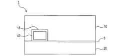
撮像装置1の構成を、図1、図2に基づき説明する。撮像装置1は、車両のウィンドシールドの内側に設置され、車両の前方を撮像するように構成されている。なお、以下の説明においては、撮像装置1の各部材の上下方向を、撮像装置1がウィンドシールドの内側に設置された状態における、その部材の上下方向として定義する。Hereinafter, embodiments of the present disclosure will be described with reference to the drawings.
[1. First Embodiment]
(1-1) Overall Configuration The configuration of the
図1に示すように、撮像装置1は、筐体5と、撮像モジュール30とを備える。撮像装置1は、内部に収容空間4を有する。収容空間4には、図2に示すように、主回路基板40が収容されている。 As shown in FIG. 1, the
(1-2)筐体の構成
筐体5は、第1ケース10と、第2ケース20と、接合部材3とを備える。筐体5は、第1ケース10と第2ケース20とが組み合わされて構成される。第1ケース10及び第2ケース20は、いずれも導体である。具体的に、第1ケース10及び第2ケース20はいずれも例えばアルミニウムを主成分とする組成の材料(例えばアルミニウム合金)によって構成されている。(1-2) Configuration of the housing The
図2に示すように、第1ケース10は第1開口部11を有する。第1開口部11は、この第1開口部11の周縁を形成する第1開口周縁11aを備える。第1開口部11には、第1開口周縁11aの周方向に沿って第1対向面12が設けられている。なお、周方向とは、第1開口部11の周縁に沿う方向、即ち第1開口周縁11aに沿う方向である。 As shown in FIG. 2, the
第2ケース20は、第1ケース10に対し、第1ケース10の第1開口部11を覆うように配置される。具体的に、第2ケース20は、第1開口部11と対向する第2開口部21を有する。第2開口部21は、この第2開口部21の周縁を形成する第2開口周縁21aを備える。 The
第2開口部21には、第2開口周縁21aの周方向に沿って第2対向面22が設けられている。第1ケース10と第2ケースとが互いに組み合わされて筐体5が形成されたとき、第1ケース10の第1対向面12と第2ケース20の第2対向面22とが互いに対向した状態となる。換言すれば、第1ケース10と第2ケース20とは、第1対向面12と第2対向面22とが互いに対向するように組み付けられる。よって、周方向とは、第2開口部21の周縁に沿う方向であるとも言える。 The
図2及び図4に示すように、本実施形態の第1ケース10は、後方側の面に、コネクタ孔15が形成されている。コネクタ孔15は、第1開口周縁11aの一部を略矩形状に切り欠いた形状となっている。そのため、第1対向面12は、第1開口周縁11aの全周のうちコネクタ孔15が形成されている範囲を除く範囲に渡って形成されている。 As shown in FIGS. 2 and 4, in the
第2対向面22は、第2開口周縁21aの全周に渡って形成されており、第1ケース10と第2ケース20とが組み付けられると、第1対向面12はその全面が第2対向面22に対向する。一方、第2対向面22は、その全面のうち第1ケース10のコネクタ孔15が形成されている領域を除く領域が第1対向面12に対向する。 The second facing
なお、コネクタ孔15は、筐体5におけるどの部位に形成されていてもよい。例えば、第1ケース10の後方側の面において、第1開口周縁11aよりも上方側に設けられていてもよい。その場合、第1対向面12は、第2対向面22と同様、第1開口周縁11aの全周に渡って形成されることになり、第1対向面12と第2対向面22とは双方の全周に渡って対向することになる。 The
接合部材3は、導電性の部材である。接合部材3は、互いに組み合わされる第1ケース10と第2ケース20との間に介在し、両者間の隙間を塞ぎ且つ両者を電気的に接合する。
接合部材3は、第1ケース10の第1対向面12と第2ケース20の第2対向面22との間における、周方向の全周に渡って設けられる。接合部材3は、薄厚テープ状の形状であり、全体としては矩形リング状の形状である。The joining
The joining
接合部材3は、図3に示すように、第1対向面12及び第2対向面22に密着するように、且つ第1ケース10と第2ケース20とを電気的に接続するように設けられている。なお、電気的に接続とは、例えば、第1ケース10と第2ケース20とを直流的に結合することを意味する。 As shown in FIG. 3, the joining
本実施形態では、第1対向面12及び第2対向面22のいずれも、全周に渡って接合部材3と対向し、接合部材3に密着する。
なお、第1ケース10の後面に設けられたコネクタ孔15には、外部コネクタ43が嵌められ、コネクタ孔15は外部コネクタ43によって塞がれる。外部コネクタ43は、その後端面が第1ケース10の後面と略同一面に位置するように配置される。そのため、図4に示すように、接合部材3における、第1ケース10側の面のうちコネクタ孔15に対向する範囲は、外部コネクタ43の下面に密着する。In the present embodiment, both the first facing
An
コネクタ孔15の対角線の長さは、λ/2以下の長さとなるように構成されている。λは、車両に搭載された装置にて使用される各種信号のうち周波数が最大の信号の波長である。例えば、車両には路車間通信用の車載機器が搭載されており、その車載機器で使用される信号の周波数帯が、車両で使用される最も高い周波数帯であり、例えば2.5GHzである。この場合、λ/2は約60mmとなる。 The diagonal length of the
このように、コネクタ孔15の対角線の長さはλ/2以下となるように構成されている。そのため、仮に、コネクタ孔15と外部コネクタ43との間、或いは外部コネクタ43と接合部材3との間に、隙間が生じたとしても、その隙間から外部へ電波が漏洩するのが抑制され、外部から筐体5の内部へ波長がλよりも長い電波が侵入するのも抑制される。 As described above, the length of the diagonal line of the
接合部材3は、第1ケース10と第2ケース20とを電気的に接続可能な導電性を持つ種々の材質の部材を用いてよい。
接合部材3は、接着剤を含んでおり、接合部材3自体、接着性を有する。そのため、接合部材3における、第1対向面12と対向する面は、一定の接着力にて第1対向面12に接着される。また、接合部材3における、第2対向面22と対向する面も、一定の接着力にて第2対向面22に接着される。As the joining
The joining
接合部材3は、例えば軟質の部材であってもよいし、硬質の部材であってもよい。また例えば、接合部材3は、初期状態では軟質あるいはペースト状であって、加熱すること或いは一定時間以上の時間経過によって硬化されるような部材であってもよい。 The joining
第1ケース10と第2ケース20との接合面(即ち第1対向面12及び第2対向面22)が、双方の開口周縁11a、21aの全周に渡って接合部材3に密着した状態となって、両者の隙間が接合部材3によって塞がれる。そのため、筐体5内部の部品等から発生する電磁波が筐体5の外に漏洩するのが抑制される。また、外部から筐体5内部への電磁波の侵入も抑制される。 A state in which the joint surface between the
(1-3)撮像モジュールの構成
撮像モジュール30は、車両前方の撮像対象を撮像してその撮像した撮像対象の画像を示す画像信号を出力するように構成されている。撮像モジュール30は、レンズ31と、撮像基板32とを備える。撮像基板32には、不図示の受光素子が設けられている。(1-3) Configuration of Imaging Module The
筐体5には、開口されたレンズ孔14が形成されている。撮像モジュール30は、基本的には筐体5の収容空間4内に収容されるが、レンズ31の一部は、レンズ孔14から筐体5の外部へ露出された状態で配置される。 An
なお、撮像モジュール30のうちレンズ31以外の構成部品が筐体5の外部に露出していてもよい。逆に、レンズ31も含め、撮像モジュール30全体が筐体5の内部に収容されていてもよい。その場合、例えば、筐体5におけるレンズ31近傍の部位を透明にし、撮像対象からの光がその透明の部位を介してレンズ31に入射されるように構成してもよい。 The components of the
本実施形態では、レンズ孔14から撮像モジュール30の一部を露出させる方向を前方、その反対方向を後方として、撮像装置1の前後方向を定義する。また、撮像装置1から前方を見たときの左右方向を、撮像装置1の左右方向として定義する。撮像装置1は、通常、前方向と車両の進行方向とが一致するように車両に取り付けられる。 In the present embodiment, the front-rear direction of the
レンズ31には、撮像対象からの光が入射される。撮像対象からの光は、レンズ31を介して受光素子に到達し、受光素子で受光される。受光素子は、受光した光に応じた信号を出力する。受光素子は、例えば、CMOSイメージセンサ等の半導体イメージセンサ素子であってもよい。 Light from the image pickup target is incident on the
撮像基板32には、信号出力回路が設けられている。信号出力回路は、レンズ31に入射された光に基づいて、より詳しくは受光素子から出力される信号に基づいて、撮像対象の画像を示す画像信号を出力する。撮像モジュール30から出力される画像信号は、主回路基板40に入力される。 The
(1-4)主回路基板40の構成
図2に示すように、主回路基板40は、信号処理回路42と、外部コネクタ43とを備える。信号処理回路42は、撮像モジュール30から出力された画像信号を処理する。外部コネクタ43は、信号処理回路42に対する外部からの信号を入力したり、信号処理回路42による処理結果を外部へ出力したりするためのコネクタである。(1-4) Configuration of
(1-5)筐体の組み付け手順
第1ケース10は、第2ケース20と接合させるための複数(例えば4つ)のねじ孔10a、10b、10c、10dを備える。一方、第2ケース20における、第1ケース10の各ねじ孔10a、10b、10c、10dと対向する位置には、それぞれ、第1ケース10と接合させるための貫通孔20a、20b、20c、20dが設けられている。(1-5) Case Assembling Procedure The
第1ケース10と第2ケース20とは、前述のように接合部材3による接着力により接合部材3を介して接合されるのに加え、複数(例えば4つ)のねじ28によっても機械的に固定される。 The
筐体5の組み付け手順は、例えば次の通りである。まず、第1ケース10の第1対向面12又は第2ケース20の第2対向面22に、接合部材3を貼り付ける。これにより、第1対向面12及び第2対向面22のうち一方が、接合部材3に密着した状態となる。 The procedure for assembling the
次に、第1ケース10と第2ケース20とを、双方の対向面12,22が対向するように組み合わせる。これにより、第1対向面12及び第2対向面22の双方が、接合部材3に密着した状態となる。 Next, the
ここで、接合部材3の硬化処理が必要な場合は、接合部材3の硬化処理を行う。例えば、接合部材3が、加熱によって硬化するように構成されている場合は、接合部材3を加熱することにより熱硬化させる。また例えば、接合部材3が、時間経過によって硬化されるように構成されている場合は、一定時間以上の時間経過を待つことによって接合部材3を硬化させる。 Here, if the joining
なお、主回路基板40を含む、筐体5の収容空間4内に収容されるべき部材については、第1ケース10と第2ケース20とが組み付けられる前の任意のタイミングで、第1ケース10又は第2ケース20に適宜配置する。 Regarding the members to be accommodated in the
第1ケース10と第2ケース20とを組み合わせて双方を接合部材3を介して接合した後、さらに、4つのねじ28によって、第1ケース10と第2ケース20とを相互に固定する。即ち、4つのねじ28を、それぞれ、第2ケース20に設けられた4つの貫通孔20a、20b、20c、20dを介して、第1ケース10に設けられた4つのねじ孔10a、10b、10c、10dに螺合させる。 After the
(1-6)第1実施形態の効果
以上説明した第1実施形態によれば、以下の(1a)~(1d)の効果を奏する。
(1a)撮像装置1の筐体5は、第1ケース10と第2ケース20とを備える。第1ケース10と第2ケース20とは、導電性の接合部材3を介して接合され、且つ電気的にも接続される。そのため、撮像装置1から外部への電磁波の漏洩、および外部から撮像装置1への電磁波の侵入が抑制される。(1-6) Effect of First Embodiment According to the first embodiment described above, the following effects (1a) to (1d) are exhibited.
(1a) The
(1b)特に、本実施形態では、接合部材3は、第1対向面12と第2対向面22との間において、周方向の全周に渡って設けられている。これにより、接合部材3は、第1対向面12及び第2対向面22に対し、周方向の全周に渡って密着する。そのため、電磁波の漏洩及び侵入がより良好に抑制される。 (1b) In particular, in the present embodiment, the joining
(1c)接合部材3は、それ自体が接着性を有し、第1対向面12及び第2対向面22の双方に接着する。そのため、接合部材3に対する第1対向面12及び第2対向面22の密着性が高まり、第1対向面12と第2対向面22との間に隙間がより生じにくくなる。 (1c) The joining
(1d)第1ケース10と第2ケース20とは、接合部材3を介して接合されるのに加え、複数のねじ28によって機械的にも固定される。そのため、接合部材3に対する第1対向面12及び第2対向面22の密着性がより高まる。 (1d) The
なお、第1ケース10は本開示における第1筐体部材に相当し、第2ケース20は本開示における第2筐体部材に相当し、信号処理回路42は本開示における信号処理部に相当し、複数のねじ28は本開示における締結部に相当する。 The
[2.第2実施形態]
第2実施形態の撮像装置50について、図5、図6を用いて説明する。撮像装置50は、筐体55と、撮像モジュール80と、主回路基板90とを備える。筐体55は、第1ケース60と、第2ケース70とを備える。第1ケース60及び第2ケース70はいずれも導体である。筐体55は、第1ケース60と第2ケース70とが組み合わされて構成される。撮像モジュール80及び主回路基板90は、筐体55の内部の収容空間54に収容される。[2. Second Embodiment]
The
第1ケース60は、第1実施形態の第1ケース10と比較して、第1対向面の形状が異なること以外は基本的には第1実施形態の第1ケース10と同じ構成である。即ち、第1ケース60は、第1開口部61及び第1開口周縁61aを備え、第1開口周縁61aの周方向に沿って第1対向面62が設けられている。また、第1ケース60には、レンズ孔64が形成されている。 The
第2ケース70も、第1実施形態の第2ケース20と比較して、第2対向面の形状が異なること以外は基本的には第1実施形態の第2ケース20と同じ構成である。即ち、第2ケース70は、第2開口部71及び第2開口周縁71aを備え、第2開口周縁71aの周方向に沿って第2対向面72が設けられている。 The
第1対向面62及び第2対向面72は、図5及び図6に示すように、周方向に垂直な断面がL字型の形状となっている。そして、図6に示すように、第1対向面62と第2対向面72との間に接合部材100が設けられる。 As shown in FIGS. 5 and 6, the first facing
接合部材100は、第1実施形態の接合部材3と同様、導電性及び接着性を有し、第1対向面62及び第2対向面72の全周に渡って対向するように設けられる。接合部材100は、第1対向面62及び第2対向面72に密着し、且つ第1ケース60と第2ケース70とを電気的に接続する。 Like the joining
本実施形態の接合部材100は、初期状態ではペースト状であり、硬化処理により硬化されるように構成されている。つまり、接合部材100は、全体として、導電性を有する接着剤である、とも言える。 The joining
なお、図5及び図6では図示を省略しているが、第1ケース60と第2ケース70とは、第1実施形態と同様、複数のねじによっても固定される。
撮像モジュール80は、入射部としてのレンズ81と、撮像基板82とを備える。レンズ81は第1実施形態のレンズ31と同じであり、撮像基板82は第1実施形態の撮像基板32と同じである。Although not shown in FIGS. 5 and 6, the
The
また、撮像モジュール80は、第1実施形態と同様、基本的には筐体55の収容空間54内に収容されるが、レンズ81の一部は、レンズ孔64から筐体55の外部へ露出された状態で配置される。 Further, the
撮像モジュール80は、さらに、ケーブル83と、モジュールコネクタ84とを備える。ケーブル83は、例えば、複数の電線が平面状に配列されてなるフラット型のケーブルである。撮像基板82内の信号出力回路にて生成された画像信号は、ケーブル83を介してモジュールコネクタ84へ伝送され、モジュールコネクタ84から出力される。 The
主回路基板90は、第1実施形態の主回路基板40と同様、信号処理回路92及び外部コネクタ93を備える。信号処理回路92及び外部コネクタ93の構成及び機能は、基本的に第1実施形態の信号処理回路42及び外部コネクタ43と同じである。 The
信号処理回路92の一部、及び外部コネクタ93は、主回路基板90における上側の板面に設けられている。主回路基板90における下側の板面には、図6に示すように、基板コネクタ96が設けられている。基板コネクタ96は、信号処理回路92と電気的に接続されている。 A part of the
基板コネクタ96には、撮像モジュール80のモジュールコネクタ84が嵌合される。つまり、主回路基板90は、撮像モジュール80の撮像基板82と基板コネクタ96及びモジュールコネクタ84を介して電気的に接続され、これにより両者間で各種信号が送受される。 The
本実施形態の主回路基板90には、孔部94が設けられている。孔部94は、主回路基板90の板面を表裏方向に貫通するように設けられている。
撮像モジュール80の一部は、主回路基板90の孔部94に挿入された状態で配置される。本実施形態では、図6に示すように、撮像モジュール80における撮像基板82の一部が主回路基板90の孔部94に挿入された状態で配置される。The
A part of the
撮像モジュール80は、一部を除き、全体的として主回路基板90の上面側に配置される。一方、基板コネクタ96は、主回路基板90の下面側に配置されている。このような位置関係により、撮像モジュール80と主回路基板90の基板コネクタ96とは、図6に示すように、孔部94を介して接続される。 The
なお、撮像モジュール80におけるどの部分が主回路基板90の孔部94に挿入された状態にされるかについては、適宜決めてよい。例えば、撮像基板82は全体が主回路基板90の上面側に配置され、ケーブル83が、主回路基板90の孔部94を貫通摺るように配置されてもよい。 It should be noted that it may be appropriately determined which portion of the
本実施形態の筐体55の組み付け手順は、例えば次の通りである。まず、第1ケース60の第1対向面62又は第2ケース70の第2対向面72に、ペースト状の接合部材100を塗布する。 The procedure for assembling the
次に、第1ケース60と第2ケース70とを、双方の対向面62,72が対向するように組み合わせる。これにより、第1対向面62及び第2対向面72の双方が、接合部材100に密着した状態となる。 Next, the
この状態で、接合部材100の硬化処理を行う。熱硬化処理の後は、第1ケース60と第2ケース70とを、不図示のねじによって固定する。
以上詳述した第2実施形態によれば、前述した第1実施形態の効果(1a)~(1d)を奏し、さらに、以下の効果を奏する。In this state, the joining
According to the second embodiment described in detail above, the effects (1a) to (1d) of the above-mentioned first embodiment are exhibited, and the following effects are further achieved.
即ち、第1対向面62及び第2対向面72が、L字断面形状に形成されている。そのため、組み付け過程において、第1ケース60と第2ケース70との水平方向の相対位置関係を、容易に適切な状態にすることができる。また、組み付け完了後も、少なくともその水平方向の相対位置関係については、仮にねじによる固定を行わなくても、適切な状態を維持させることができる。 That is, the first facing
[3.他の実施形態]
以上、本開示の実施形態について説明したが、本開示は上述の実施形態に限定されることなく、種々変形して実施することができる。[3. Other embodiments]
Although the embodiments of the present disclosure have been described above, the present disclosure is not limited to the above-described embodiments, and can be variously modified and implemented.
(3-1)第1対向面と第2対向面の形状は、第1実施形態に示した平面形状、及び第2実施形態に示したL字断面形状とは異なる形状であってもよい。
例えば、第1対向面及び第2対向面の少なくとも一方に、周方向に沿って、断面が円弧状となるような溝を設け、その溝にリング状の接合部材を嵌めることによって、第1対向面と第2対向面とを接合部材を介して密着させるようにしてもよい。(3-1) The shapes of the first facing surface and the second facing surface may be different from the planar shape shown in the first embodiment and the L-shaped cross-sectional shape shown in the second embodiment.
For example, by providing a groove having an arcuate cross section along the circumferential direction on at least one of the first facing surface and the second facing surface and fitting a ring-shaped joining member into the groove, the first facing surface is formed. The surface and the second facing surface may be brought into close contact with each other via the joining member.
また例えば、第1対向面及び第2対向面の何れか一方にリブ状の突部を設け、他方にその突部が挿入される溝を設け、その溝に突部と共に接合部材を充填させるようにしてもよい。具体例を、図7及び図8に示す。 Further, for example, a rib-shaped protrusion is provided on either one of the first facing surface and the second facing surface, a groove into which the protrusion is inserted is provided on the other, and the groove is filled with the joint member together with the protrusion. You may do it. Specific examples are shown in FIGS. 7 and 8.
図7は、第1ケース120の第1対向面122に、周方向に沿ってリブ状の突部123が設けられ、第2ケース130の第2対向面132に、周方向に沿って溝部133が形成された、撮像装置の一例を示している。 In FIG. 7, a rib-shaped
第1ケース120の突部123は、第2対向面132に向けて突出するように設けられている。第2対向面132の溝部133は、突部123と対向する部位に設けられ、突部123が挿入されると共に接合部材140が充填されるように構成されている。 The
図7に示す撮像装置における、第1ケース120と第2ケース130とを組み付ける際の組み付け工程は、概ね次の通りである。まず、図7の上段は、第1ケース120と第2ケース130とが離れていてまだ組み付けられていない状態を示している。 The assembly process for assembling the
この状態で、図7の中段に示すように、第2ケース130の溝部133に、例えばペースト状の軟質の接合部材140を充填させる。
溝部133に接合部材140を充填させた後、第2ケース130に対し、第1ケース120を、第1ケース120の突部123が第2ケース130の溝部133に挿入されるように被せる。In this state, as shown in the middle part of FIG. 7, the
After filling the
第1ケース120の突部123が第2ケース130の溝部133に挿入されると、図7の下段に示すように、突部123は、溝部133に充填されている接合部材140に埋設されていく。本実施形態では、前述の通り、溝部133が完全に塞がれるように接合部材140が充填される。そのため、突部123が溝部133に挿入されていくと、図7の下段に示すように、接合部材140の一部が溝部から溢れていく。 When the
そして、図7の下段に示す状態まで突部123が溝部133に挿入された状態で、接合部材140の硬化処理を行う。なお、突部123を溝部133にどの程度挿入させるかについては、適宜決めてよい。例えば、突部123の先端が溝部133の底部に到達するまで、或いは第1対向面122が第2対向面132に当接するまで、突部123を溝部133に挿入させてもよい。 Then, the joining
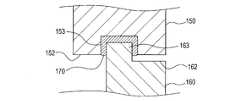
図8は、第2ケース160の第2対向面162が、第2実施形態と同じようにL字断面形状となっており、第1ケース150の第1対向面152に溝部153が形成された、撮像装置の一例を示している。このような形状により、図8に示すように、第1ケース150の外側面及び第2ケース160の外側面は略同一面上に位置する一方、第1ケース150の内側面及び第2ケース160の内側面は同一面上には存在しない。 In FIG. 8, the second facing
図8に示す撮像装置における、第1ケース150と第2ケース160とを組み付ける際の組み付け工程は、概ね次の通りである。まず、第1ケース150の溝部153に、例えばペースト状の軟質の接合部材170を充填させる。次に、第1ケース150に対し、第2ケース160を、第2ケース160の突部163が第1ケース150の溝部153に挿入されるように被せる。 The assembly process for assembling the
第2ケース160の突部163が第1ケース150の溝部153に挿入されると、図8に示すように、突部163は、溝部153に充填されている接合部材170に埋設されていく。接合部材170の充填量によっては、或いは埋設量によっては、接合部材170の一部が溝部153から溢れていく。そして、図8に示す状態まで突部163が溝部153に挿入された状態で、接合部材170の硬化処理を行う。 When the
(3-2)各対向面は、開口部の周縁の全周に渡って設けられていなくてもよい。また、接合部材は、周方向の全周に渡って設けられていなくてもよい。接合部材は、周方向における一部の範囲に設けられていてもよい。例えば、周方向において接合部材が設けられない範囲が1箇所以上あってもよい。 (3-2) Each facing surface may not be provided over the entire circumference of the peripheral edge of the opening. Further, the joining member may not be provided over the entire circumference in the circumferential direction. The joining member may be provided in a partial range in the circumferential direction. For example, there may be one or more areas in which the joining member is not provided in the circumferential direction.
その場合、周方向に連続して特定の信号波長(例えば前述のλ)の1/2以上の範囲で接合部材が設けられない領域が生じないように、接合部材を設けるようにしてもよい。
(3-3)接合部材は、第1対向面及び第2対向面の双方に対して接着性を有していなくてもよい。接合部材は、例えば、第1対向面及び第2対向面のうち何れか一方に対して接着を有し、他方に対しては接着性はなく単にその他方に密着した状態になるだけでもよい。In that case, the joining member may be provided so as not to generate a region in which the joining member is not provided continuously in the range of 1/2 or more of the specific signal wavelength (for example, λ described above) in the circumferential direction.
(3-3) The joining member may not have adhesiveness to both the first facing surface and the second facing surface. The joining member may, for example, have adhesion to either one of the first facing surface and the second facing surface, have no adhesiveness to the other, and may simply be in close contact with the other.
(3-4)また、接合部材は、全体として接着剤を含んでいなくてもよく、複数の層が積層された積層構造であってもよい。即ち、接合部材は、接着剤を含まないか若しくは接着剤の含有量が低い層と、接着剤を主成分とする層とが積層されて構成されていてもよい。 (3-4) Further, the joining member may not contain an adhesive as a whole, and may have a laminated structure in which a plurality of layers are laminated. That is, the joining member may be configured by laminating a layer containing no adhesive or having a low content of the adhesive and a layer containing the adhesive as a main component.
積層構造の接合部材の一例を、図9に示す。図9は、第1実施形態の撮像装置1に対し、第1実施形態に示した接合部材3に代えて、積層構造の接合部材200を設けた例を示している。 FIG. 9 shows an example of a joining member having a laminated structure. FIG. 9 shows an example in which the
図9に示す接合部材200は、中間層201と、第1接着層202と、第2接着層203とを備える。中間層201、第1接着層202及び第2接着層203は、いずれも、導電性の部材である。 The joining
中間層201は、接着剤を含まないか若しくは接着剤の含有量が低い。一方、第1接着層202及び第2接着層203は、接着剤を含み、少なくとも中間層201よりも高い接着性を有する。 The
第1接着層202は、第1対向面に接触且つ接着され、中間層201を第1対向面に接着させる。換言すれば、第1接着層202は、接合部材を第1対向面に接着させる。
第2接着層203は、第2対向面に接触且つ接着され、中間層201を第2対向面に接着させる。換言すれば、第2接着層203は、接合部材を第2対向面に接着させる。The first
The second
なお、図9に示す接合部材200において、第1接着層202及び第2接着層203のうち何れか一方を省いてもよい。
また、図9に示す接合部材200において、中間層201も接着性を有していてもよい。例えば、中間層201として第1実施形態の接合部材3と同じ材質のものを用いてもよい。In the joining
Further, in the joining
因みに、第1実施形態の接合部材3及び第2実施形態の接合部材100は、いずれも、それ自体が接着性を有している。そのため、これら各接合部材3、100は、接着性を有するか否かという観点で言えば、全体として1つの接着層である、と言える。 Incidentally, both the joining
(3-5)第1実施形態では、締結部として4本のねじ28が用いられているが、締結部の数は4つ以外でもよく、また締結部の位置も任意に決めてよい。
また、第1筐体部材と第2筐体部材とを機械的に固定する締結部として、ねじを用いることは一例であって、ねじ以外を用いてもよい。例えば、締結部として、第1筐体部材と第2筐体部材とをかしめる部位を少なくとも1箇所以上設けてもよい。また例えば、締結部として、スナップフィットを少なくとも1箇所以上設けてもよい。(3-5) In the first embodiment, four
Further, using a screw as a fastening portion for mechanically fixing the first housing member and the second housing member is an example, and a screw other than the screw may be used. For example, at least one portion for crimping the first housing member and the second housing member may be provided as the fastening portion. Further, for example, at least one snap fit may be provided as the fastening portion.
(3-6)第1筐体部材と第2筐体部材との固定について、接合部材が接着性を有していれば、ねじ等の締結部を用いることなく、接合部材の接着力のみで両筐体部材を固定してもよい。 (3-6) Regarding the fixing between the first housing member and the second housing member, if the joining member has adhesiveness, only the adhesive force of the joining member is used without using a fastening portion such as a screw. Both housing members may be fixed.
(3-7)上記実施形態では、撮像モジュールを1つ備えた撮像装置を示したが、本開示は、撮像モジュールを複数備えた撮像装置にも適用可能である。
(3-8)第1筐体部材及び第2筐体部材の各開口周縁の形状、構造等は、上記各実施形態に示した形状、構造等に限定されない。また、上記各実施形態では、第1ケース及び第2ケースがアルミニウムを主成分とする材料で構成されている例を示したが、第1ケース及び第2ケースはアルミニウム以外の金属を主成分とする材料で構成されていてもよい。(3-7) In the above embodiment, the image pickup apparatus provided with one image pickup module is shown, but the present disclosure is also applicable to the image pickup apparatus provided with a plurality of image pickup modules.
(3-8) The shape, structure, etc. of each opening peripheral edge of the first housing member and the second housing member are not limited to the shape, structure, etc. shown in the above embodiments. Further, in each of the above embodiments, an example in which the first case and the second case are composed of a material containing aluminum as a main component is shown, but the first case and the second case contain a metal other than aluminum as a main component. It may be composed of the material to be used.
(3-9)上記実施形態における1つの構成要素が有する複数の機能を、複数の構成要素によって実現したり、1つの構成要素が有する1つの機能を、複数の構成要素によって実現したりしてもよい。また、複数の構成要素が有する複数の機能を、1つの構成要素によって実現したり、複数の構成要素によって実現される1つの機能を、1つの構成要素によって実現したりしてもよい。また、上記実施形態の構成の一部を省略してもよい。また、上記実施形態の構成の少なくとも一部を、他の上記実施形態の構成に対して付加又は置換してもよい。なお、特許請求の範囲に記載した文言から特定される技術思想に含まれるあらゆる態様が本開示の実施形態である。 (3-9) A plurality of functions possessed by one component in the above embodiment may be realized by a plurality of components, or one function possessed by one component may be realized by a plurality of components. May be good. Further, a plurality of functions possessed by the plurality of components may be realized by one component, or one function realized by the plurality of components may be realized by one component. Further, a part of the configuration of the above embodiment may be omitted. Further, at least a part of the configuration of the above embodiment may be added or replaced with the configuration of the other above embodiment. It should be noted that all aspects included in the technical idea specified from the wording described in the claims are embodiments of the present disclosure.
1,50…撮像装置、3,100,140,170,200…接合部材、4,54…収容空間、5,55…筐体、10,60,120,150…第1ケース、11,61…第1開口部、11a,61a…第1開口周縁、12,62,122,152…第1対向面、20,70,130,160…第2ケース、21,71…第2開口部、21a,71a…第2開口周縁、22,72,132,162…第2対向面、28…ねじ、30,80…撮像モジュール、31,81…レンズ、32…撮像基板、40,90…主回路基板、42,92…信号処理回路、94…孔部、123,163…突部、133,153…溝部、201…中間層、202…第1接着層、203…第2接着層。 1,50 ... Imaging device, 3,100, 140, 170, 200 ... Joining member, 4,54 ... Accommodating space, 5,55 ... Housing, 10,60,120,150 ... First case, 11,61 ... 1st opening, 11a, 61a ... 1st opening peripheral edge, 12, 62, 122, 152 ... 1st facing surface, 20, 70, 130, 160 ... 2nd case, 21, 71 ... 2nd opening, 21a, 71a ... 2nd aperture peripheral edge, 22,72,132,162 ... 2nd facing surface, 28 ... screw, 30,80 ... imaging module, 31,81 ... lens, 32 ... imaging board, 40,90 ... main circuit board, 42, 92 ... Signal processing circuit, 94 ... Hole, 123, 163 ... Protrusion, 133, 153 ... Groove, 201 ... Intermediate layer, 202 ... First adhesive layer, 203 ... Second adhesive layer.
Claims (7)
Translated fromJapanese内部に収容空間を有する筐体(5、55)と、
少なくとも一部が前記収容空間に収容され、撮像対象を撮像してその撮像した前記撮像対象の画像を示す画像信号を出力するように構成された撮像モジュール(30、80)と、
前記収容空間に収容され、前記撮像モジュールから出力された前記画像信号を処理するように構成された信号処理部(42、92)と、
を備え、
前記筐体は、
開口部(11、61)を有し、前記開口部の周縁に沿って第1対向面(12、62、122、152)が設けられた第1筐体部材(10、60、120、150)と、
前記開口部を覆うように配置され、前記第1対向面と対向する第2対向面(22、72、132、162)が設けられた第2筐体部材(20、70、130、160)と、
前記第1対向面と前記第2対向面との間における、前記開口部の周縁に沿う周方向の少なくとも一部において、前記第1対向面及び前記第2対向面に密着するように且つ前記第1筐体部材と前記第2筐体部材とを電気的に接続するように設けられた、導電性の接合部材(3、100、140、170、200)と、
を備え、
前記第1対向面及び前記第2対向面のうちの一方には、他方に向けて突出する突部(123、163)が前記周方向に沿って設けられ、
前記第1対向面及び前記第2対向面のうちの前記他方における、少なくとも前記突部と対向する部位には、前記突部が挿入されると共に前記接合部材の少なくとも一部が充填されるように構成された溝部(133、153)が設けられている、
撮像装置。An image pickup device (1, 50) mounted on a vehicle.
A housing (5, 55) with an internal storage space,
An image pickup module (30, 80) configured to image an image pickup target and output an image signal indicating the captured image of the image pickup target, at least a part of which is accommodated in the accommodation space.
A signal processing unit (42, 92) accommodated in the accommodation space and configured to process the image signal output from the image pickup module, and
Equipped with
The housing is
A first housing member (10, 60, 120, 150) having an opening (11, 61) and having a first facing surface (12, 62, 122, 152) along the periphery of the opening. When,
With a second housing member (20, 70, 130, 160) arranged so as to cover the opening and provided with a second facing surface (22, 72, 132, 162) facing the first facing surface. ,
The first facing surface and the second facing surface so as to be in close contact with the first facing surface and the second facing surface at least in a circumferential direction along the peripheral edge of the opening between the first facing surface and the second facing surface. Conductive joining members (3, 100, 140, 170, 200) provided so as to electrically connect one housing member and the second housing member, and
Equippedwith
One of the first facing surface and the second facing surface is provided with protrusions (123, 163) protruding toward the other along the circumferential direction.
The protrusion is inserted into at least a portion of the first facing surface and the other of the second facing surfaces facing the protrusion, and at least a part of the joining member is filled. The configured groove portions (133, 153) are provided.
Imaging device.
前記接合部材は、前記第1対向面と前記第2対向面との間において、前記周方向に連続して特定の信号波長の1/2以上の範囲で前記接合部材が設けられない領域が生じないように設けられている、撮像装置。The image pickup apparatus according to claim 1.
In the joining member, a region is formed between the first facing surface and the second facing surface in which the joining member is not provided continuously in the circumferential direction in a range of ½ or more of a specific signal wavelength. An image pickup device that is provided so that it does not exist.
前記接合部材は、前記第1対向面と前記第2対向面との間における前記周方向の全周に渡って設けられている、撮像装置。The image pickup apparatus according to claim 1 or 2.
The joining member is an image pickup apparatus provided over the entire circumference in the circumferential direction between the first facing surface and the second facing surface.
前記接合部材は、前記第1対向面及び前記第2対向面のうち少なくとも一方に接着するように構成されている、撮像装置。The image pickup apparatus according to any one of claims 1 to 3.
An image pickup apparatus in which the joining member is configured to adhere to at least one of the first facing surface and the second facing surface.
前記接合部材は、前記第1対向面及び前記第2対向面のうち少なくとも一方に接触し且つ前記接合部材を前記少なくとも一方に接着させるように構成された接着層(3、100、140、170、202、203)を備える、撮像装置。The image pickup apparatus according to claim 4.
The bonding member is an adhesive layer (3, 100, 140, 170, configured to contact at least one of the first facing surface and the second facing surface and to bond the joining member to the at least one. An imaging device comprising 202, 203).
前記接合部材とは別に設けられ、前記第1筐体部材と前記第2筐体部材とを互いに固定するように構成された締結部(28)を備える、撮像装置。The image pickup apparatus according to any one of claims 1 to 5.
An image pickup apparatusincluding a fastening portion (28) provided separately from the joining member and configured to fix the first housing member and the second housing member to each other .
内部に収容空間を有する筐体(55)と、 A housing (55) having a storage space inside,
少なくとも一部が前記収容空間に収容され、撮像対象からの光が入射される入射部(81)を有し、前記入射部に入射された光に基づいて前記撮像対象の画像を示す画像信号を出力するように構成された撮像モジュール(80)と、 An image signal indicating an image of the imaging target based on the light incident on the incident portion having at least a part of the incident portion (81) accommodated in the accommodation space and incident with the light from the imaging target. An image pickup module (80) configured to output, and
前記収容空間に収容される回路基板であって、前記撮像モジュールから出力された前記画像信号が入力される信号入力部(96)、及び前記信号入力部に入力された前記画像信号を処理する信号処理回路(92)が設けられると共に、前記回路基板を表裏方向に貫通する孔部(94)が設けられたられた回路基板(90)と、 A circuit board accommodated in the accommodation space, the signal input unit (96) into which the image signal output from the image pickup module is input, and a signal for processing the image signal input to the signal input unit. A circuit board (90) provided with a processing circuit (92) and a hole portion (94) penetrating the circuit board in the front and back directions.
を備え、 Equipped with
前記撮像モジュールのうち少なくとも前記入射部は、前記回路基板に対して前記回路基板の両板面のうち一方の板面側に配置され、 At least the incident portion of the image pickup module is arranged on one of the two plate surfaces of the circuit board with respect to the circuit board.
前記信号入力部は、前記回路基板の両板面のうち前記一方の板面側とは反対側の板面に配置され、 The signal input unit is arranged on the plate surface of both plate surfaces of the circuit board, which is opposite to the plate surface side of the one.
前記撮像モジュールと前記信号入力部とは、前記孔部を介して電気的に接続されるように構成されており、 The image pickup module and the signal input unit are configured to be electrically connected via the hole portion.
前記筐体は、 The housing is
第1開口部(61)を有し、前記第1開口部の周縁に沿って第1対向面(62)が設けられた第1筐体部材(60)と、 A first housing member (60) having a first opening (61) and having a first facing surface (62) along the peripheral edge of the first opening.
前記第1開口部を覆うように配置され、前記第1開口部と対向する第2開口部(71)を有し、前記第2開口部の周縁に沿って、前記第1対向面と対向する第2対向面(72)が設けられた第2筐体部材(70)と、 It has a second opening (71) that is arranged so as to cover the first opening and faces the first opening, and faces the first facing surface along the peripheral edge of the second opening. A second housing member (70) provided with a second facing surface (72), and
前記第1対向面と前記第2対向面の間において、前記第1対向面及び前記第2対向面に密着するように且つ前記第1筐体部材と前記第2筐体部材とを電気的に接続するように設けられた、導電性の接合部材(100)と、 Between the first facing surface and the second facing surface, the first housing member and the second housing member are electrically contacted so as to be in close contact with the first facing surface and the second facing surface. A conductive joining member (100) provided to connect and
を備える撮像装置(50)。 (50).
Priority Applications (4)
| Application Number | Priority Date | Filing Date | Title |
|---|---|---|---|
| JP2017173917AJP7059541B2 (en) | 2017-09-11 | 2017-09-11 | Imaging device |
| DE102018215391.4ADE102018215391A1 (en) | 2017-09-11 | 2018-09-11 | Imaging device |
| CN201811057532.3ACN109495674B (en) | 2017-09-11 | 2018-09-11 | Image forming apparatus with a plurality of image forming units |
| US16/127,683US10812688B2 (en) | 2017-09-11 | 2018-09-11 | Imaging apparatus |
Applications Claiming Priority (1)
| Application Number | Priority Date | Filing Date | Title |
|---|---|---|---|
| JP2017173917AJP7059541B2 (en) | 2017-09-11 | 2017-09-11 | Imaging device |
Publications (2)
| Publication Number | Publication Date |
|---|---|
| JP2019050506A JP2019050506A (en) | 2019-03-28 |
| JP7059541B2true JP7059541B2 (en) | 2022-04-26 |
Family
ID=65441505
Family Applications (1)
| Application Number | Title | Priority Date | Filing Date |
|---|---|---|---|
| JP2017173917AActiveJP7059541B2 (en) | 2017-09-11 | 2017-09-11 | Imaging device |
Country Status (4)
| Country | Link |
|---|---|
| US (1) | US10812688B2 (en) |
| JP (1) | JP7059541B2 (en) |
| CN (1) | CN109495674B (en) |
| DE (1) | DE102018215391A1 (en) |
Families Citing this family (2)
| Publication number | Priority date | Publication date | Assignee | Title |
|---|---|---|---|---|
| JP7407017B2 (en)* | 2020-02-28 | 2023-12-28 | 株式会社東海理化電機製作所 | Installation equipment |
| DE102020108771A1 (en) | 2020-03-30 | 2021-09-30 | Connaught Electronics Ltd. | Method for assembling a camera for a vehicle, pre-assembly module for a camera and camera |
Family Cites Families (24)
| Publication number | Priority date | Publication date | Assignee | Title |
|---|---|---|---|---|
| JPS60166197A (en) | 1984-02-08 | 1985-08-29 | Ihara Chem Ind Co Ltd | Screw Press |
| JPH0488099U (en)* | 1990-12-17 | 1992-07-30 | ||
| JPH11239288A (en)* | 1998-02-20 | 1999-08-31 | Fuji Heavy Ind Ltd | Case body structure for video camera |
| JP2007274624A (en) | 2006-03-31 | 2007-10-18 | Citizen Miyota Co Ltd | Camera module |
| JP4900118B2 (en)* | 2007-07-31 | 2012-03-21 | コニカミノルタオプト株式会社 | Camera module and electronic equipment |
| JP2009212446A (en) | 2008-03-06 | 2009-09-17 | Smk Corp | Shield method for electronic component enclosure and shield member |
| JP5494927B2 (en)* | 2009-08-03 | 2014-05-21 | 株式会社リコー | Camera unit and sensing device |
| KR20110063158A (en)* | 2009-12-04 | 2011-06-10 | 삼성전기주식회사 | Camera module |
| JP5273296B2 (en)* | 2010-04-16 | 2013-08-28 | パナソニック株式会社 | Digital camera |
| CN102331612A (en)* | 2010-07-13 | 2012-01-25 | 鸿富锦精密工业(深圳)有限公司 | Lens module and portable electronic device using the lens module |
| JP2012047816A (en) | 2010-08-24 | 2012-03-08 | Sharp Corp | Camera module, and method of manufacturing the same |
| JP2012113186A (en)* | 2010-11-26 | 2012-06-14 | Mitsumi Electric Co Ltd | Camera module |
| WO2012137267A1 (en)* | 2011-04-05 | 2012-10-11 | パナソニック株式会社 | Solid-state image pickup device, and method for manufacturing solid-state image pickup device |
| WO2013123161A1 (en) | 2012-02-17 | 2013-08-22 | Magna Electronics, Inc. | Vehicle vision system with light baffling system |
| US9871971B2 (en) | 2011-08-02 | 2018-01-16 | Magma Electronics Inc. | Vehicle vision system with light baffling system |
| KR101428842B1 (en)* | 2011-11-08 | 2014-08-08 | 엘지이노텍 주식회사 | Camera module for Vehicle |
| KR101376882B1 (en)* | 2012-11-15 | 2014-03-20 | 삼성전기주식회사 | Camera for car |
| KR101952853B1 (en)* | 2013-07-12 | 2019-02-27 | 삼성전기주식회사 | Camera module |
| CN104954635B (en)* | 2014-03-26 | 2019-06-07 | 鸿富锦精密工业(深圳)有限公司 | camera module |
| US9896039B2 (en)* | 2014-05-09 | 2018-02-20 | Magna Electronics Inc. | Vehicle vision system with forward viewing camera |
| KR102248085B1 (en)* | 2014-10-17 | 2021-05-04 | 엘지이노텍 주식회사 | Camera module using for automobile |
| JP6344297B2 (en)* | 2015-04-16 | 2018-06-20 | 株式会社デンソー | Imaging device and printed circuit board used therefor |
| DE102015110262A1 (en)* | 2015-06-25 | 2016-12-29 | Connaught Electronics Ltd. | Camera for a motor vehicle with shielding device, driver assistance system and motor vehicle |
| JP6733522B2 (en)* | 2016-11-29 | 2020-08-05 | 株式会社デンソー | Imaging device |
- 2017
- 2017-09-11JPJP2017173917Apatent/JP7059541B2/enactiveActive
- 2018
- 2018-09-11DEDE102018215391.4Apatent/DE102018215391A1/enactivePending
- 2018-09-11CNCN201811057532.3Apatent/CN109495674B/enactiveActive
- 2018-09-11USUS16/127,683patent/US10812688B2/enactiveActive
Also Published As
| Publication number | Publication date |
|---|---|
| DE102018215391A1 (en) | 2019-03-14 |
| CN109495674A (en) | 2019-03-19 |
| US10812688B2 (en) | 2020-10-20 |
| JP2019050506A (en) | 2019-03-28 |
| CN109495674B (en) | 2021-05-07 |
| US20190082082A1 (en) | 2019-03-14 |
Similar Documents
| Publication | Publication Date | Title |
|---|---|---|
| JP7495327B2 (en) | Automotive Camera Assembly | |
| JP6721745B2 (en) | Imaging device and vehicle | |
| CN107565246B (en) | Connector module and vehicle-mounted camera using the same | |
| US8970700B2 (en) | Imaging apparatus | |
| US9345134B2 (en) | Printed wiring board | |
| JP6732438B2 (en) | Imaging device | |
| JPWO2012137267A1 (en) | Solid-state imaging device and method for manufacturing solid-state imaging device | |
| JP2014011565A (en) | Camera module | |
| JP7059541B2 (en) | Imaging device | |
| JP2010041709A (en) | Camera module | |
| JP2015122718A (en) | Grounding part, electronic device, imaging device, and grounding part production method | |
| JP2023530312A (en) | The camera module | |
| JPH11239288A (en) | Case body structure for video camera | |
| JP4031104B2 (en) | Stereo camera | |
| US9236655B2 (en) | Antenna assembly and method of making same | |
| JP2004079226A (en) | Connection structure and method for connection of flat electric cable | |
| JP2023531901A (en) | The camera module | |
| CN113632446B (en) | Electronic equipment, camera devices, and moving objects | |
| JP4407297B2 (en) | Imaging device, imaging device manufacturing method, imaging device, imaging device mounting substrate, and electronic device | |
| US20150062424A1 (en) | Camera module and method for assembling same | |
| JP6803222B2 (en) | Imaging device | |
| JP2004088227A (en) | Portable wireless devices | |
| JP2013081092A (en) | Imaging element mounting module | |
| KR20220082369A (en) | Camera module | |
| JP2011059164A (en) | Electronic equipment |
Legal Events
| Date | Code | Title | Description |
|---|---|---|---|
| A621 | Written request for application examination | Free format text:JAPANESE INTERMEDIATE CODE: A621 Effective date:20200806 | |
| A977 | Report on retrieval | Free format text:JAPANESE INTERMEDIATE CODE: A971007 Effective date:20210729 | |
| A131 | Notification of reasons for refusal | Free format text:JAPANESE INTERMEDIATE CODE: A131 Effective date:20210824 | |
| A521 | Request for written amendment filed | Free format text:JAPANESE INTERMEDIATE CODE: A523 Effective date:20211013 | |
| TRDD | Decision of grant or rejection written | ||
| A01 | Written decision to grant a patent or to grant a registration (utility model) | Free format text:JAPANESE INTERMEDIATE CODE: A01 Effective date:20220315 | |
| A61 | First payment of annual fees (during grant procedure) | Free format text:JAPANESE INTERMEDIATE CODE: A61 Effective date:20220328 | |
| R151 | Written notification of patent or utility model registration | Ref document number:7059541 Country of ref document:JP Free format text:JAPANESE INTERMEDIATE CODE: R151 | |
| R250 | Receipt of annual fees | Free format text:JAPANESE INTERMEDIATE CODE: R250 |