JP7058162B2 - Linkage display device - Google Patents
Linkage display deviceDownload PDFInfo
- Publication number
- JP7058162B2 JP7058162B2JP2018064705AJP2018064705AJP7058162B2JP 7058162 B2JP7058162 B2JP 7058162B2JP 2018064705 AJP2018064705 AJP 2018064705AJP 2018064705 AJP2018064705 AJP 2018064705AJP 7058162 B2JP7058162 B2JP 7058162B2
- Authority
- JP
- Japan
- Prior art keywords
- display device
- liquid crystal
- connecting component
- crystal display
- component
- Prior art date
- Legal status (The legal status is an assumption and is not a legal conclusion. Google has not performed a legal analysis and makes no representation as to the accuracy of the status listed.)
- Active
Links
Images


Classifications
- G—PHYSICS
- G06—COMPUTING OR CALCULATING; COUNTING
- G06F—ELECTRIC DIGITAL DATA PROCESSING
- G06F3/00—Input arrangements for transferring data to be processed into a form capable of being handled by the computer; Output arrangements for transferring data from processing unit to output unit, e.g. interface arrangements
- G06F3/14—Digital output to display device ; Cooperation and interconnection of the display device with other functional units
- G06F3/1423—Digital output to display device ; Cooperation and interconnection of the display device with other functional units controlling a plurality of local displays, e.g. CRT and flat panel display
- G06F3/1446—Digital output to display device ; Cooperation and interconnection of the display device with other functional units controlling a plurality of local displays, e.g. CRT and flat panel display display composed of modules, e.g. video walls
- G—PHYSICS
- G02—OPTICS
- G02F—OPTICAL DEVICES OR ARRANGEMENTS FOR THE CONTROL OF LIGHT BY MODIFICATION OF THE OPTICAL PROPERTIES OF THE MEDIA OF THE ELEMENTS INVOLVED THEREIN; NON-LINEAR OPTICS; FREQUENCY-CHANGING OF LIGHT; OPTICAL LOGIC ELEMENTS; OPTICAL ANALOGUE/DIGITAL CONVERTERS
- G02F1/00—Devices or arrangements for the control of the intensity, colour, phase, polarisation or direction of light arriving from an independent light source, e.g. switching, gating or modulating; Non-linear optics
- G02F1/01—Devices or arrangements for the control of the intensity, colour, phase, polarisation or direction of light arriving from an independent light source, e.g. switching, gating or modulating; Non-linear optics for the control of the intensity, phase, polarisation or colour
- G02F1/13—Devices or arrangements for the control of the intensity, colour, phase, polarisation or direction of light arriving from an independent light source, e.g. switching, gating or modulating; Non-linear optics for the control of the intensity, phase, polarisation or colour based on liquid crystals, e.g. single liquid crystal display cells
- G02F1/133—Constructional arrangements; Operation of liquid crystal cells; Circuit arrangements
- G02F1/1333—Constructional arrangements; Manufacturing methods
- G02F1/13336—Combining plural substrates to produce large-area displays, e.g. tiled displays
- G—PHYSICS
- G02—OPTICS
- G02F—OPTICAL DEVICES OR ARRANGEMENTS FOR THE CONTROL OF LIGHT BY MODIFICATION OF THE OPTICAL PROPERTIES OF THE MEDIA OF THE ELEMENTS INVOLVED THEREIN; NON-LINEAR OPTICS; FREQUENCY-CHANGING OF LIGHT; OPTICAL LOGIC ELEMENTS; OPTICAL ANALOGUE/DIGITAL CONVERTERS
- G02F1/00—Devices or arrangements for the control of the intensity, colour, phase, polarisation or direction of light arriving from an independent light source, e.g. switching, gating or modulating; Non-linear optics
- G02F1/01—Devices or arrangements for the control of the intensity, colour, phase, polarisation or direction of light arriving from an independent light source, e.g. switching, gating or modulating; Non-linear optics for the control of the intensity, phase, polarisation or colour
- G02F1/13—Devices or arrangements for the control of the intensity, colour, phase, polarisation or direction of light arriving from an independent light source, e.g. switching, gating or modulating; Non-linear optics for the control of the intensity, phase, polarisation or colour based on liquid crystals, e.g. single liquid crystal display cells
- G02F1/133—Constructional arrangements; Operation of liquid crystal cells; Circuit arrangements
- G02F1/1333—Constructional arrangements; Manufacturing methods
- G02F1/133308—Support structures for LCD panels, e.g. frames or bezels
- H—ELECTRICITY
- H05—ELECTRIC TECHNIQUES NOT OTHERWISE PROVIDED FOR
- H05K—PRINTED CIRCUITS; CASINGS OR CONSTRUCTIONAL DETAILS OF ELECTRIC APPARATUS; MANUFACTURE OF ASSEMBLAGES OF ELECTRICAL COMPONENTS
- H05K5/00—Casings, cabinets or drawers for electric apparatus
- H05K5/0017—Casings, cabinets or drawers for electric apparatus with operator interface units
- H—ELECTRICITY
- H05—ELECTRIC TECHNIQUES NOT OTHERWISE PROVIDED FOR
- H05K—PRINTED CIRCUITS; CASINGS OR CONSTRUCTIONAL DETAILS OF ELECTRIC APPARATUS; MANUFACTURE OF ASSEMBLAGES OF ELECTRICAL COMPONENTS
- H05K5/00—Casings, cabinets or drawers for electric apparatus
- H05K5/30—Side-by-side or stacked arrangements
- G—PHYSICS
- G02—OPTICS
- G02F—OPTICAL DEVICES OR ARRANGEMENTS FOR THE CONTROL OF LIGHT BY MODIFICATION OF THE OPTICAL PROPERTIES OF THE MEDIA OF THE ELEMENTS INVOLVED THEREIN; NON-LINEAR OPTICS; FREQUENCY-CHANGING OF LIGHT; OPTICAL LOGIC ELEMENTS; OPTICAL ANALOGUE/DIGITAL CONVERTERS
- G02F1/00—Devices or arrangements for the control of the intensity, colour, phase, polarisation or direction of light arriving from an independent light source, e.g. switching, gating or modulating; Non-linear optics
- G02F1/01—Devices or arrangements for the control of the intensity, colour, phase, polarisation or direction of light arriving from an independent light source, e.g. switching, gating or modulating; Non-linear optics for the control of the intensity, phase, polarisation or colour
- G02F1/13—Devices or arrangements for the control of the intensity, colour, phase, polarisation or direction of light arriving from an independent light source, e.g. switching, gating or modulating; Non-linear optics for the control of the intensity, phase, polarisation or colour based on liquid crystals, e.g. single liquid crystal display cells
- G02F1/133—Constructional arrangements; Operation of liquid crystal cells; Circuit arrangements
- G02F1/1333—Constructional arrangements; Manufacturing methods
- G02F1/133308—Support structures for LCD panels, e.g. frames or bezels
- G02F1/133314—Back frames
- G—PHYSICS
- G02—OPTICS
- G02F—OPTICAL DEVICES OR ARRANGEMENTS FOR THE CONTROL OF LIGHT BY MODIFICATION OF THE OPTICAL PROPERTIES OF THE MEDIA OF THE ELEMENTS INVOLVED THEREIN; NON-LINEAR OPTICS; FREQUENCY-CHANGING OF LIGHT; OPTICAL LOGIC ELEMENTS; OPTICAL ANALOGUE/DIGITAL CONVERTERS
- G02F1/00—Devices or arrangements for the control of the intensity, colour, phase, polarisation or direction of light arriving from an independent light source, e.g. switching, gating or modulating; Non-linear optics
- G02F1/01—Devices or arrangements for the control of the intensity, colour, phase, polarisation or direction of light arriving from an independent light source, e.g. switching, gating or modulating; Non-linear optics for the control of the intensity, phase, polarisation or colour
- G02F1/13—Devices or arrangements for the control of the intensity, colour, phase, polarisation or direction of light arriving from an independent light source, e.g. switching, gating or modulating; Non-linear optics for the control of the intensity, phase, polarisation or colour based on liquid crystals, e.g. single liquid crystal display cells
- G02F1/133—Constructional arrangements; Operation of liquid crystal cells; Circuit arrangements
- G02F1/1333—Constructional arrangements; Manufacturing methods
- G02F1/133308—Support structures for LCD panels, e.g. frames or bezels
- G02F1/133322—Mechanical guidance or alignment of LCD panel support components
- G—PHYSICS
- G09—EDUCATION; CRYPTOGRAPHY; DISPLAY; ADVERTISING; SEALS
- G09G—ARRANGEMENTS OR CIRCUITS FOR CONTROL OF INDICATING DEVICES USING STATIC MEANS TO PRESENT VARIABLE INFORMATION
- G09G2300/00—Aspects of the constitution of display devices
- G09G2300/02—Composition of display devices
- G09G2300/026—Video wall, i.e. juxtaposition of a plurality of screens to create a display screen of bigger dimensions
Landscapes
- Physics & Mathematics (AREA)
- Engineering & Computer Science (AREA)
- Nonlinear Science (AREA)
- General Physics & Mathematics (AREA)
- Theoretical Computer Science (AREA)
- Mathematical Physics (AREA)
- Chemical & Material Sciences (AREA)
- Crystallography & Structural Chemistry (AREA)
- Optics & Photonics (AREA)
- General Engineering & Computer Science (AREA)
- Human Computer Interaction (AREA)
- Multimedia (AREA)
- Microelectronics & Electronic Packaging (AREA)
- Devices For Indicating Variable Information By Combining Individual Elements (AREA)
- Liquid Crystal (AREA)
Description
Translated fromJapanese特許法第30条第2項適用 第5回鉄道技術展2017、平成29年11月29日から12月1日開催
本発明は、連結表示装置に関する。 The present invention relates to a connected display device.
従来、多画面型の表示装置の一例として下記特許文献1に記載されたものが知られている。この特許文献1に記載された多画面表示装置は、画像を表示する表示部と表示部の外周を囲む枠部とを備えた表示装置を複数用い、夫々の表示装置の枠部同士を互いに近接させてなり、枠部の外周面には、外周面より表示部側に向け窪む凹部と、外周面より表示部側の反対側に向け突出する凸部と、が設けられ、互いに近接する表示装置の夫々の凹部と凸部とが互いに嵌合する構成とされることを特徴とする。 Conventionally, the one described in the following
上記した特許文献1に記載された多画面表示装置を構成する夫々の表示装置は、背面に固定用パネルが固定されており、夫々の固定用パネルが略梯子状の組み立て用架台に取り付けられることで、夫々の表示装置の連結が図られている。しかしながら、組み立て用架台に対して固定ネジによって固定される夫々の表示装置は、固定ネジによる固定箇所が夫々の表示装置の配置に応じて個別に設定されている。つまり、夫々の表示装置は、多画面表示装置における配置に応じた専用設計となっており、高コストとなっていた。また、略梯子状の組み立て用架台を製造するのも高コストであった。 Each display device constituting the multi-screen display device described in
本発明は上記のような事情に基づいて完成されたものであって、低コスト化を図ることを目的とする。 The present invention has been completed based on the above circumstances, and an object thereof is to reduce the cost.
本発明の連結表示装置は、互いに隣り合うよう並んでいて複数ずつの固定部が設けられる複数の表示装置と、隣り合う前記表示装置に跨る形で配されて隣り合う前記表示装置を連結する連結部品と、前記固定部に対して固定されることで隣り合う前記表示装置と前記連結部品とを保持する複数の保持部品と、を備える連結表示装置であって、複数ずつの前記固定部は、それぞれの前記表示装置において中心を対称点とした点対称状に配されている。 The connected display device of the present invention connects a plurality of display devices arranged side by side so as to be adjacent to each other and provided with a plurality of fixing portions, and the adjacent display devices arranged so as to straddle the adjacent display devices. A connection display device including a component and a plurality of holding parts for holding the display device and the connection component adjacent to each other by being fixed to the fixing portion, wherein each of the fixing portions is a plurality of holding parts. In each of the display devices, they are arranged in a point-symmetrical manner with the center as a point of symmetry.
このようにすれば、隣り合う複数の表示装置に画像が表示されるので、単独の表示装置での表示に比べると、大画面での表示が可能となる。隣り合う表示装置に設けられた複数ずつの固定部に複数の保持部品が固定されることで、隣り合う表示装置と隣り合う表示装置に跨る形で配される連結部品との保持が図られる。ここで、例えば表示装置の部品交換などを行う場合には、保持部品を取り外して連結部品による表示装置同士の連結状態を解除すればよく、利便性に優れる。そして、複数ずつの固定部は、それぞれの表示装置において中心を対称点とした点対称状に配されているから、例えば隣り合う表示装置のいずれか一方を他方に対して反転させても、隣り合う表示装置の各固定部に対して各保持部品を固定して連結部材の保持を図ることができる。従って、隣り合う表示装置において少なくとも固定部が設けられた部品を共通化することが可能となるので、低コスト化を図る上で好適となる。 By doing so, since the image is displayed on a plurality of adjacent display devices, it is possible to display on a large screen as compared with the display on a single display device. By fixing a plurality of holding parts to a plurality of fixing portions provided in adjacent display devices, it is possible to hold the adjacent display devices and the connecting parts arranged so as to straddle the adjacent display devices. Here, for example, when the parts of the display device are replaced, the holding parts may be removed to release the connection state between the display devices by the connecting parts, which is excellent in convenience. Since the plurality of fixed portions are arranged in a point-symmetrical manner with the center as the point of symmetry in each display device, for example, even if one of the adjacent display devices is inverted with respect to the other, the fixed portions are adjacent to each other. Each holding component can be fixed to each fixing portion of the matching display device to hold the connecting member. Therefore, it is possible to share at least the parts provided with the fixed portions in the adjacent display devices, which is suitable for cost reduction.
本発明によれば、低コスト化を図ることができる。 According to the present invention, cost reduction can be achieved.
<実施形態1>
本発明の実施形態1を図1から図12によって説明する。本実施形態では、液晶表示装置(表示装置)10を用いた連結液晶表示装置(連結表示装置)50について例示する。なお、各図面の一部にはX軸、Y軸及びZ軸を示しており、各軸方向が各図面で示した方向となるように描かれている。また、図2,図8から図10に示す上側を表側とし、同図下側を裏側とする。<
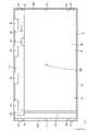
先に液晶表示装置10について説明する。液晶表示装置10は、図1に示すように、全体として横長の略方形状をなしている。液晶表示装置10は、図2及び図3に示すように、画像を表示する液晶パネル(表示パネル)11と、液晶パネル11に表示のための光を供給するバックライト装置(照明装置)12と、を備え、これらが枠状のベゼル13などにより一体的に保持される。さらには、液晶表示装置10は、液晶パネル11及びバックライト装置12の駆動を制御するためのコントロール基板(制御基板)14を備える。液晶表示装置10は、図1に示すように、液晶パネル11における中央側部分が画像を表示する表示領域とされるのに対し、液晶パネル11における外周側部分及びベゼル13の全域が表示領域を取り囲むよう額縁状をなす非表示領域(額縁領域)とされる。 First, the liquid
液晶パネル11は、図2に示すように、一対のガラス基板が所定のギャップを隔てた状態で貼り合わせられるとともに、両ガラス基板間に電界印加に伴って光学特性が変化する物質である液晶分子を含む液晶層(図示せず)が封入された構成とされる。一方のガラス基板(アレイ基板、アクティブマトリクス基板)の内面側には、互いに直交するソース配線とゲート配線とに接続されたスイッチング素子(例えばTFT)と、ソース配線とゲート配線とに囲まれた方形状の領域に配されてスイッチング素子に接続される画素電極と、がマトリクス状に平面配置される他、配向膜等が設けられている。他方のガラス基板(対向基板、CF基板)の内面側には、R(赤色),G(緑色),B(青色)等の各着色部が所定配列でマトリクス状に平面配置されたカラーフィルタが設けられる他、各着色部間に配されて格子状をなす遮光層(ブラックマトリクス)、画素電極と対向状をなすベタ状の対向電極、配向膜等が設けられている。なお、両ガラス基板の外面側には、それぞれ偏光板が配されている。また、液晶パネル11における長辺方向がX軸方向と一致し、短辺方向がY軸方向と一致し、さらに厚さ方向がZ軸方向と一致している。 As shown in FIG. 2, the
液晶パネル11における端部には、図2に示すように、複数のパネル用フレキシブル基板(フレキシブル基板)15の一端側が接続されている。パネル用フレキシブル基板15には、図示しないドライバがCOF(Chip On Film)実装されており、このドライバは、内部に駆動回路を有するLSIチップからなる。パネル用フレキシブル基板15の他端側には、コントロール基板14が接続されている。コントロール基板14は、バックライト装置12の裏側に配されている。従って、液晶パネル11とコントロール基板14とに接続されるパネル用フレキシブル基板15は、折り返し状に屈曲(湾曲)されている。パネル用フレキシブル基板15は、絶縁性及び可撓性を有する合成樹脂材料(例えばポリイミド系樹脂等)からなる基材を備え、その基材上に多数本の配線パターン(図示せず)を有している。コントロール基板14は、パネル用フレキシブル基板15に比べると高い剛性を有する(リジッドな)基材を備え、その基材の板面上に各種電子部品などが実装されている。上記したパネル用フレキシブル基板15は、液晶パネル11及びコントロール基板14の双方に接続される「パネル接続部品」である。 As shown in FIG. 2, one end side of a plurality of panel flexible substrates (flexible substrates) 15 is connected to the end portion of the
バックライト装置12は、図2に示すように、表側(液晶パネル11側)に向けて開口する略箱型をなすシャーシ(同じ部品、筐体)18と、シャーシ18の開口を覆う形で配される光学部材(光学シート)19と、光学部材19を表側から支持するフレーム20と、を備える。さらに、シャーシ18内には、光源であるLED(Light Emitting Diode:発光ダイオード)21と、LED21が実装されるLED基板(光源基板)22と、LED21からの光を導光して光学部材19(液晶パネル11)へと導く導光板23と、導光板23の裏側に配置される反射シート24と、が備えられる。そして、このバックライト装置12は、その短辺方向(Y軸方向)についての片方の端部にLED21が配されており、LED21からの光が導光板23に対して片側から入光される片側入光タイプのエッジライト型(サイドライト型)とされる。続いて、バックライト装置12の各構成部品について詳しく説明する。 As shown in FIG. 2, the
シャーシ18は、金属製とされ、図2に示すように、液晶パネル11と同様に横長の略方形状をなす底部18Aと、底部18Aの各辺の外端からそれぞれ立ち上がる側部18Bと、からなる。底部18Aは、その長辺方向がX軸方向(水平方向)と一致し、短辺方向がY軸方向(鉛直方向)と一致している。底部18Aには、図3に示すように、Y軸方向に沿って延在する一対の短辺側端部がそれぞれ所定幅にわたって裏側に突出することで一対の段部(被連結部、被取付部)18Cが設けられている。段部18Cは、底部18Aにおいて短辺方向に沿ってほぼ全長にわたって延在する形で設けられている。段部18Cには、後述する連結部品51が取り付けられるようになっている。また、各側部18Bには、フレーム20及びベゼル13が固定可能とされる。 As shown in FIG. 2, the
光学部材19は、図2に示すように、シャーシ18の開口を覆うとともに、液晶パネル11と導光板23との間に介在する形で配されることで、導光板23からの出射光を透過するとともにその透過光に所定の光学作用を付与しつつ液晶パネル11に向けて出射させる。光学部材19は、複数枚(本実施形態では4枚)が備えられ、その具体的な種類としては、例えば拡散シート、レンズシート(プリズムシート)、反射型偏光シート、レンズ拡散板などがあり、これらの中から適宜に選択して使用することが可能である。フレーム20は、横長の枠状をなしており、光学部材19及び導光板23の外周縁部をほぼ全周にわたって表側から押さえて支持するとともに、液晶パネル11の外周縁部をほぼ全周にわたって裏側から受けて支持する。 As shown in FIG. 2, the
LED21は、図2に示すように、LED基板22に固着される基板部上にLEDチップを封止材により封止した構成とされる。LED21は、LEDチップが例えば青色光を単色発光するものとされ、封止材に蛍光体(黄色蛍光体、緑色蛍光体、赤色蛍光体など)が分散配合されることで全体として白色光を発する。LED21は、自身の発光面21Aとは反対側の面が次述するLED基板22に実装されており、いわゆる上面発光型とされる。 As shown in FIG. 2, the
LED基板22は、図2に示すように、X軸方向に沿って延在する板状をなしており、その板面がX軸方向及びZ軸方向に並行する姿勢でシャーシ18内に収容される。LED基板22は、複数のLED21が実装される実装面が次述する導光板23の端面(入光端面23A)と対向する形で配されるとともに、LED21の実装面とは反対側の板面がシャーシ18の側部18Bに接する形で取り付けられている。LED基板22におけるLED21の実装面には、金属膜(銅箔など)からなり、各LED21の端子などに接続される配線パターン(図示せず)が形成されている。LED21は、LED基板22における実装面においてX軸方向に沿って複数が間隔を空けて並んで配されている。LED基板22には、図示しない給電用コネクタが設けられており、この給電用コネクタにバックライト用フレキシブルフラットケーブル(光源給電部品)25の一端側が接続されている。バックライト用フレキシブルフラットケーブル25は、その他端側がシャーシ18の外部に引き出されるとともにコントロール基板14に接続されている(図3を参照)。バックライト用フレキシブルフラットケーブル25は、互いに並行する複数の配線部を絶縁性及び可撓性を有する合成樹脂製のフィルムにより挟み込んだ構成とされる。 As shown in FIG. 2, the
導光板23は、ほぼ透明な合成樹脂材料(例えばPMMAなどのアクリル樹脂やポリカーボネートなど)とされ、屈折率が空気よりも十分に高くなっている。導光板23は、図2に示すように、液晶パネル11などと同様に横長の板状をなしていてシャーシ18によりその周りが取り囲まれた形で収容されるとともに、液晶パネル11及び光学部材19の直下位置に配されている。導光板23は、その外周端面のうち一方(図2に示す左側)の長辺側の端面が、LED21と対向状をなしていてLED21からの光が入射される入光端面(光源対向端面)23Aとされる。導光板23は、表裏一対の板面のうち、表側(液晶パネル11側)を向いた板面が、光を液晶パネル11に向けて出射させる出光板面23Bとされ、裏側を向いた板面が出光板面23Bとは反対側の出光反対板面23Cとされる。このような構成により、導光板23は、LED21からY軸方向に沿って発せられた光を入光端面23Aから導入するとともに、その光を内部で伝播させた後にZ軸方向に沿って立ち上げて出光板面23Bから光学部材19側(表側、光出射側)へ向けて出射させる機能を有している。 The
反射シート24は、図2に示すように、導光板23の出光反対板面23Cを覆う形で配される。反射シート24は、光反射性に優れており、導光板23の出光反対板面23Cから漏れた光を表側(出光板面23B側)に向けて効率的に立ち上げることができる。 As shown in FIG. 2, the
本実施形態に係る液晶表示装置10は、図4に示すように、液晶パネル11の駆動を制御するための表示制御部(表示パネル制御部)26と、バックライト装置12に備わるLED21の駆動を制御するためのLED制御部(光源制御部)27と、を少なくとも有している。表示制御部26は、映像信号を処理する映像信号処理回路部と、映像信号処理回路部からの出力信号に基づいて各画素を駆動する画素駆動部と、を有しており、コントロール基板14に設けられている。LED制御部27は、LED21を駆動するLED駆動部を有しており、コントロール基板14に設けられている。コントロール基板14には、表示制御部26及びLED制御部27の動作をそれぞれ制御するCPU28が設けられている。 As shown in FIG. 4, the liquid
コントロール基板14には、図2及び図3に示すように、一端側が外部のパネル用信号供給源に接続されたフレキシブル基板(パネル用信号供給源共々図示せず)の他端側に設けられたコネクタが接続されて映像信号の供給を受けるパネル用入力コネクタ29と、一端側が外部のバックライト用信号供給源に接続されたフレキシブル基板(バックライト用信号供給源共々図示せず)の他端側に設けられたコネクタが接続されてバックライト信号の供給を受けるバックライト用入力コネクタ30と、一端側がLED基板22の給電用コネクタに接続されたバックライト用フレキシブルフラットケーブル25の他端側が接続されるバックライト用出力コネクタ33と、が設けられている。外部のパネル用信号供給源は、元の映像信号をコントロール基板14のパネル用入力コネクタ29に供給するものであり、コントロール基板14では供給された元の映像信号が処理され、処理された画像信号に基づいて液晶パネル11に画像が表示される。外部のバックライト用信号供給源は、元のバックライト信号をコントロール基板14のバックライト用入力コネクタ30に供給するものであり、コントロール基板14では供給された元のバックライト信号が処理され、処理されたLED駆動信号に基づいてLED21が駆動される。 As shown in FIGS. 2 and 3, the
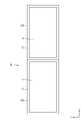
続いて、連結液晶表示装置50について説明する。連結液晶表示装置50は、図5及び図6に示すように、2つの液晶表示装置10をX軸方向(並び方向)について隣り合う形で並べた上で相互に連結した構成とされる。このようにすれば、2つの液晶表示装置10によって横長の画像を表示する上で好適となる。この連結液晶表示装置50の具体的な用途としては、例えば電車の乗降口周りに設置されるデジタルサイネージなどに好適であり、表示する画像としては電車の路線図や広告などが好適である。 Subsequently, the connected liquid
そして、本実施形態に係る連結液晶表示装置50は、図5及び図6に示すように、X軸方向に沿って並ぶ2つの液晶表示装置10が互いにY軸方向(並び方向と直交する並び直交方向)について天地が反転した姿勢とされている。詳しくは、X軸方向に沿って並ぶ2つの液晶表示装置10のうちの一方の液晶表示装置10は、パネル用フレキシブル基板15がY軸方向について図5及び図6に示す上側に配される第1姿勢とされる。これに対し、X軸方向に沿って並ぶ2つの液晶表示装置10のうちの他方の液晶表示装置10は、パネル用フレキシブル基板15がY軸方向について図5及び図6に示す下側に配されていて上記した第1姿勢に対してY軸方向について天地が反転した第2姿勢とされる。なお、本実施形態では、図5に示す左側(図6に示す右側)の液晶表示装置10を第1姿勢とし、図5に示す右側(図6に示す左側)の液晶表示装置10を第2姿勢とする。これに対し、表示制御部26は、第1姿勢と第2姿勢との双方で液晶パネル11に表示される画像におけるY軸方向についての向きが同一となるよう液晶パネル11の駆動を制御する。このようにすれば、X軸方向について隣り合う液晶表示装置10が互いに反転した姿勢で連結されていても、隣り合う液晶表示装置10の各液晶パネル11のそれぞれに適切な画像を表示させることができる。上記したように互いに反転した姿勢で隣り合う2つの液晶表示装置10に備わる合計4つの段部18Cは、図6に示すように、連結液晶表示装置50におけるX軸方向についての両端部に2つが分散配置されるとともに、連結液晶表示装置50におけるX軸方向についての中央部に2つがX軸方向について隣接する形で配置される。 Then, in the connected liquid
具体的な表示駆動に関して説明すると、表示制御部26は、外部のパネル用信号供給源から供給される映像信号に基づいて、図6に示される第1姿勢での表示のための第1表示信号と、第2姿勢での表示のための第2表示信号と、を選択的に出力することが可能とされる。より詳しくは、外部のパネル用信号供給源から出力される映像信号には、第1表示トリガー信号と第2表示トリガー信号とのうちのいずれかが含まれており、第1表示トリガー信号が含まれていた場合には表示制御部26は第1表示信号を出力し、第2表示トリガー信号が含まれていた場合には表示制御部26は第2表示信号を出力する。なお、第1表示トリガー信号及び第2表示トリガー信号は、パネル用入力コネクタ29に備わる同一端子に対して供給されるようになっており、第1表示トリガー信号及び第2表示トリガー信号のうちの一方が高い電圧値の信号とされ、他方が低い電圧値の信号とされる。外部のパネル用信号供給源が第1表示トリガー信号と第2表示トリガー信号とのうちのどちらを出力するかに関しては、設置された液晶表示装置10の姿勢に基づいて外部のパネル用信号供給源の設定を調整することで制御することが可能とされる。従って、第1姿勢とされる図6に示す右側の液晶表示装置10に関しては、外部のパネル用信号供給源から出力される映像信号に第1表示トリガー信号を含ませるようにすれば、表示制御部26からは第1表示信号が出力されてパネル用フレキシブル基板15を介して液晶パネル11に供給される。これにより、第1姿勢とされた液晶表示装置10の液晶パネル11には、第1表示信号によりY軸方向について適切な向きの画像が表示される。一方、第2姿勢とされる図6に示す左側の液晶表示装置10に関しては、外部のパネル用信号供給源から出力される映像信号に第2表示トリガー信号を含ませるようにすれば、表示制御部26からは第2表示信号が出力されてパネル用フレキシブル基板15を介して液晶パネル11に供給される。これにより、第2姿勢とされた液晶表示装置10の液晶パネル11には、第2表示信号によりY軸方向について適切な向きの画像が表示される。このように、液晶表示装置10の姿勢に応じて外部のパネル用信号供給源から出力される映像信号に第1表示トリガー信号と第2表示トリガー信号とのいずれを含ませるかを調整することで、液晶パネル11に表示される画像におけるY軸方向について向きを適正化することができる。 Explaining the specific display drive, the
連結液晶表示装置50において隣り合う液晶表示装置10同士を連結するための連結構造について詳しく説明する。この連結構造は、隣り合う液晶表示装置10に跨る形で配されて隣り合う液晶表示装置10を連結する連結部品51と、隣り合う液晶表示装置10と連結部品51とを保持するための保持部品52と、各液晶表示装置10に設けられて保持部品52を固定するための固定部31と、を少なくとも有する。このうち、保持部品52は、外周面にねじ山が螺刻形成された軸部を有するビスやねじなどとされる。 The connection structure for connecting the adjacent liquid
上記した連結構造のうち、液晶表示装置10に備わる構造について説明する。液晶表示装置10を構成するシャーシ18の底部18Aにおける段部18Cには、図7及び図8に示すように、上記した固定部31に加えて、液晶表示装置10に対して連結部品51を位置決めするための液晶表示装置側位置決め部(表示装置側位置決め部)32が設けられている。つまり、固定部31及び液晶表示装置側位置決め部32は、液晶表示装置10の構成部品のうちの同じ部品であるシャーシ18に設けられている。固定部31は、段部18Cを厚さ方向(Z軸方向)に貫通する孔状をなしており、その内周面に対して保持部品52が螺合可能とされる。固定部31は、図6に示すように、段部18Cにおいてその延在方向(Y軸方向、並び直交方向)に沿って複数が間隔を空けて並んで配されている。具体的には、固定部31は、段部18Cにおいて延在方向についての中央位置に1つ設けられるとともに、延在方向についての両端部付近に2つずつ設けられており、合計5つが延在方向についての中央位置に対して対称状(点対称状、線対称状)に配されている。なお、これらの固定部31に対して固定される保持部品52は、固定部31と同数備えられている。液晶表示装置側位置決め部32は、図7及び図8に示すように、段部18CをZ軸方向に沿って裏側に向けて部分的に突出させる形で設けられている。液晶表示装置側位置決め部32は、図6に示すように、段部18Cにおいて延在方向に沿って複数が間隔を空けて並んで配されている。具体的には、液晶表示装置側位置決め部32は、段部18Cにおいて延在方向についての両端部付近において2つずつ並ぶ固定部31に対して中央寄りの位置に1つずつ設けられており、合計2つが延在方向についての中央位置に対して対称状(点対称状、線対称状)に配されている。 Among the above-mentioned connection structures, the structure provided in the liquid
そして、複数ずつの固定部31及び液晶表示装置側位置決め部32は、図3に示すように、液晶表示装置10において中心10Cを対称点とした点対称状に配されている。このようにすれば、連結液晶表示装置50において隣り合う2つの液晶表示装置10は、図6に示すように、互いに天地が反転した姿勢(第1姿勢及び第2姿勢)とされているが、各液晶表示装置10において中心10Cに対する複数ずつの固定部31及び液晶表示装置側位置決め部32の配置が同一となる。従って、連結液晶表示装置50において隣り合う液晶表示装置10が互いに反転した姿勢であっても、隣り合う液晶表示装置10の各固定部31に対して各保持部品52を固定して連結部品51の保持を図ることができる。これにより、隣り合う液晶表示装置10において少なくとも固定部31が設けられた部品であるシャーシ18を共通化することができるので、低コスト化を図る上で好適となる。しかも、連結液晶表示装置50において隣り合う液晶表示装置10は、同一とされているので、液晶表示装置10の製造コストをさらに低廉化させることができる。 As shown in FIG. 3, the plurality of fixed
連結部品51には、図6に示すように、連結液晶表示装置50の短辺方向(Y軸方向)に沿って延在する第1連結部品53と、連結液晶表示装置50の長辺方向(X軸方向)に沿って延在する一対の第2連結部品54と、が含まれている。第1連結部品53は、連結液晶表示装置50におけるX軸方向についての中央部と重畳するよう配されている。より詳しくは、第1連結部品53は、連結液晶表示装置50におけるX軸方向についての中央部において隣接配置された2つの段部18Cに跨るとともにこれら2つの段部18Cをほぼ全長にわたって裏側から覆う形で配されている。第1連結部品53は、隣接する2つの段部18Cと対向し且つ当接する基部53Aと、基部53Aにおける幅方向(X軸方向)についての両端部からZ軸方向に沿って段部18C側とは反対側(外側)に向けて突出する一対の側板部53Bと、から構成される。基部53Aにおける幅方向についての中央位置は、隣り合う液晶表示装置10の境界位置とほぼ一致している。 As shown in FIG. 6, the connecting
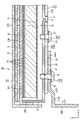
一対の第2連結部品54は、図6に示すように、連結液晶表示装置50におけるY軸方向についての両端部と重畳するよう配されている。より詳しくは、各第2連結部品54は、図10に示すように、隣接する2つの段部18Cに加えてそれら段部18Cが設けられた各シャーシ18の底部18Aに対してその長辺方向に沿って全長にわたって裏側に重なる形で配されている。各第2連結部品54は、図8に示すように、隣り合う液晶表示装置10の各シャーシ18の底部18Aと対向する基部54Aと、基部54Aにおける幅方向(Y軸方向)についての外側の一端部からZ軸方向に沿ってシャーシ18側とは反対側(外側)に向けて突出する側板部54Bと、からそれぞれ構成されている。一対の第2連結部品54は、同一部品とされる。各第2連結部品54の基部54Aは、図10に示すように、長さ方向(X軸方向)についての中央部が第1連結部品53の基部53Aにおける長さ方向(Y軸方向)についての端部と重畳するよう配されており、その重畳部分の一部が他の大部分に対して段差状に表側に張り出す第1張出部(重畳部分)54A1とされる。この第1張出部54A1は、第1連結部品53における第1張出部54A1との重畳部分53A1に当接されている。各第2連結部品54の基部54Aにおける長さ方向についての両端部は、他の大部分に対して段差状に表側に張り出す一対ずつの第2張出部(非重畳部分)54A2とされる。これら一対ずつの第2張出部54A2は、第1連結部品53とは非重畳となる非重畳部分であり、連結液晶表示装置50における長辺方向についての両端部(各液晶表示装置10におけるX軸方向についての第1連結部品53側とは反対側の各端部)に対して当接されている。従って、これらの張出部54A1,54A2によって第2連結部品54の基部54Aは、大部分が各液晶表示装置10に対してZ軸方向について間隔を空けて裏側に配されている。これにより、第2連結部品54が各液晶表示装置10に備えられる基板類などの部品に対して干渉し難くなる。 As shown in FIG. 6, the pair of second connecting
各連結部品53,54に備わる各基部53A,54Aには、図8から図10に示すように、固定部31に対して固定される保持部品52を通すための固定部連通孔55,56がそれぞれ設けられている。これら固定部連通孔55,56は、各連結部品53,54が各液晶表示装置10に対してX軸方向及びY軸方向について位置合わせされた状態において、各液晶表示装置10の各固定部31と平面に視て重畳する位置に、各固定部31と同数配されている。具体的には、第1連結部品53の基部53Aには、図6,図7及び図9に示すように、隣接配置された2つの段部18Cのそれぞれに設けられた10個の固定部31と平面に視て重畳する位置に同数の第1固定部連通孔55が開口形成されている。第1連結部品53の基部53Aのうち、その長さ方向(Y軸方向)についての両端部を除いた中央側部分、つまり第2連結部品54とは非重畳となる非重畳部分には、6個の第1固定部連通孔55が配されている。これら6個の第1固定部連通孔55を通して固定部31に固定される6個の保持部品52は、第1連結部品53を単独で液晶表示装置10に対して保持するものであり、これらを区別のため「非重畳保持部品52A」と言う。 As shown in FIGS. 8 to 10, each of the
第1連結部品53の基部53Aのうち、その長さ方向についての両端部、つまり第2連結部品54との重畳部分53A1には、図6,図7及び図10に示すように、4個の第1固定部連通孔55が配されている。これに対し、第2連結部品54の基部54Aのうち、その長さ方向についての中央部、つまり第1連結部品53と重畳する第1張出部54A1には、4個の第2固定部連通孔56が配されている。これら4個の第2固定部連通孔56は、第1連結部品53側の4個の第1固定部連通孔55と連通するよう重畳配置されており、これら4個ずつの固定部連通孔55,56を通して固定部31に固定される4個の保持部品52は、第1連結部品53及び第2連結部品54を一括して液晶表示装置10に対して保持するものであり、これらを区別のため「重畳保持部品52B」と言う。さらには、第2連結部品54の基部54Aのうち、その長さ方向についての両端部、つまり第1連結部品53とは非重畳とされる一対の第2張出部54A2には、4個の第2固定部連通孔56が配されている。これら4個の第2固定部連通孔56を通して固定部31に固定される4個の保持部品52は、第2連結部品54を単独で液晶表示装置10に対して保持するものであり、これらを区別のため「非重畳保持部品52A」と言う。また、各連結部品53,54に備わる各側板部53B,54Bは、例えば連結液晶表示装置50が設置される設置対象物(図示せず)に対して固定する際に利用可能とされる。 Of the
第1連結部品53の基部53Aのうち、液晶表示装置側位置決め部32と重畳する位置には、図7及び図8に示すように、液晶表示装置側位置決め部32に対して凹凸嵌合される連結部品側位置決め部57が設けられている。連結部品側位置決め部57は、基部53Aを厚さ方向(Z軸方向)に貫通する孔状をなしており、その内側に突起状をなす液晶表示装置側位置決め部32が嵌合されるようになっている。連結部品側位置決め部57は、X軸方向及びY軸方向について間隔を空けた位置に合計で4つ、各段部18Cの各液晶表示装置側位置決め部32と重畳するよう配されている。組み付けに際しては、液晶表示装置側位置決め部32及び連結部品側位置決め部57を凹凸嵌合させることで、各液晶表示装置10に対する第1連結部品53のX軸方向及びY軸方向(液晶表示装置10の表示面に沿う方向)についての位置決めを図ることができる。 As shown in FIGS. 7 and 8, the
第1連結部品53の基部53Aにおける第2連結部品54に対する重畳部分53A1には、図7及び図8に示すように、第1連結部品側位置決め部58が設けられている。第1連結部品側位置決め部58は、基部53AをZ軸方向に沿って裏側(重畳する第2連結部品54)に向けて部分的に突出させる形で設けられている。これに対し、第2連結部品54の基部54Aにおける第1張出部54A1には、第1連結部品側位置決め部58が凹凸嵌合される第2連結部品側位置決め部59が設けられている。第2連結部品側位置決め部59は、第1張出部54A1を厚さ方向に貫通する孔状をなしており、その内側に突起状をなす第1連結部品側位置決め部58が嵌合されるようになっている。第1連結部品側位置決め部58及び第2連結部品側位置決め部59は、第1連結部品53における長さ方向についての端部を液晶表示装置10に対して保持させるための4つの保持部品52(2つずつの非重畳保持部品52A及び重畳保持部品52B)に対して平面に視て中心となる位置に配されている。組み付けに際しては、第1連結部品側位置決め部58及び第2連結部品側位置決め部59を凹凸嵌合させることで、第1連結部品53に対する第2連結部品54のX軸方向及びY軸方向についての位置決めを図ることができる。 As shown in FIGS. 7 and 8, a first connecting component
本実施形態は以上のような構造であり、続いて連結液晶表示装置50の組付方法について説明する。まず、図11に示すように、2つの液晶表示装置10のうちの一方を第1姿勢とし、他方を第2姿勢としつつ、それらの液晶表示装置10をX軸方向について隣り合うよう配置する。この状態で互いに隣接する2つの段部18Cに対して重畳するよう第1連結部品53の組み付けを行う。このとき、第1連結部品53の連結部品側位置決め部57を、各液晶表示装置10の液晶表示装置側位置決め部32に対して凹凸嵌合させることで、図12に示すように、第1連結部品53が各液晶表示装置10に対してX軸方向及びY軸方向について位置決めされる(図8を参照)。この状態では、第1連結部品53の各第1固定部連通孔55が、各液晶表示装置10において対応する各固定部31に対して連通しているので、各第1固定部連通孔55に各非重畳保持部品52Aを通しつつ各固定部31に対して各非重畳保持部品52Aを固定する。これにより、第1連結部品53が各液晶表示装置10を連結した状態で保持される。 The present embodiment has the above-mentioned structure, and subsequently, a method of assembling the connected liquid
続いて、一対の第2連結部品54を、各液晶表示装置10及び第1連結部品53に対してそれぞれ組み付ける。このとき、第2連結部品54の第2連結部品側位置決め部59を、第1連結部品53の第1連結部品側位置決め部58に対して凹凸嵌合させることで、図6に示すように、第2連結部品54が第1連結部品53並びに各液晶表示装置10に対してX軸方向及びY軸方向について位置決めされる(図8を参照)。この状態では、第2連結部品54の各第2固定部連通孔56が、第1連結部品53において対応する各第1固定部連通孔55や各液晶表示装置10において対応する各固定部31に対してそれぞれ連通している。従って、各第2固定部連通孔56に各非重畳保持部品52A及び各重畳保持部品52Bを通しつつ各固定部31に対して各非重畳保持部品52A及び各重畳保持部品52Bを固定する。これにより、第2連結部品54が第1連結部品53と共に各液晶表示装置10を連結した状態で保持される。このとき、各重畳保持部品52Bは、第1連結部品53及び第2連結部品54を一括して各液晶表示装置10に対して保持しているので、仮に全ての保持部品を非重畳保持部品52Aとした場合に比べると、組付工数及び部品点数などの削減を図る上で好適となっている。 Subsequently, the pair of second connecting
以上説明したように本実施形態の連結液晶表示装置(連結表示装置)50は、互いに隣り合うよう並んでいて複数ずつの固定部31が設けられる複数の液晶表示装置(表示装置)10と、隣り合う液晶表示装置10に跨る形で配されて隣り合う液晶表示装置10を連結する連結部品51と、固定部31に対して固定されることで隣り合う液晶表示装置10と連結部品51とを保持する複数の保持部品52と、を備えており、複数ずつの固定部31は、それぞれの液晶表示装置10において中心10Cを対称点とした点対称状に配されている。 As described above, the connected liquid crystal display device (connected display device) 50 of the present embodiment is adjacent to a plurality of liquid crystal display devices (display device) 10 which are arranged side by side so as to be adjacent to each other and are provided with a plurality of fixed
このようにすれば、隣り合う複数の液晶表示装置10に画像が表示されるので、単独の液晶表示装置10での表示に比べると、大画面での表示が可能となる。隣り合う液晶表示装置10に設けられた複数ずつの固定部31に複数の保持部品52が固定されることで、隣り合う液晶表示装置10と隣り合う液晶表示装置10に跨る形で配される連結部品51との保持が図られる。ここで、例えば液晶表示装置10の部品交換などを行う場合には、保持部品52を取り外して連結部品51による液晶表示装置10同士の連結状態を解除すればよく、利便性に優れる。そして、複数ずつの固定部31は、それぞれの液晶表示装置10において中心10Cを対称点とした点対称状に配されているから、例えば隣り合う液晶表示装置10のいずれか一方を他方に対して反転させても、隣り合う液晶表示装置10の各固定部31に対して各保持部品52を固定して連結部品51の保持を図ることができる。従って、隣り合う液晶表示装置10において少なくとも固定部31が設けられた部品であるシャーシ18を共通化することが可能となるので、低コスト化を図る上で好適となる。また、従来では、ディスプレイの背面に固定される固定用パネルと、固定用パネルが取り付けられる梯子状の架台と、を要していたのに比べると、本実施形態では、部品点数を削減することができるとともに、大幅な軽量化を図ることができる。 By doing so, since the image is displayed on a plurality of adjacent liquid
また、隣り合う液晶表示装置10と連結部品51とには、互いに凹凸嵌合される液晶表示装置側位置決め部(表示装置側位置決め部)32と連結部品側位置決め部57とがそれぞれ設けられており、液晶表示装置側位置決め部32は、対称点(中心10C)に関して点対称状に複数配されている。このようにすれば、隣り合う液晶表示装置10を連結部品51により連結する際には、液晶表示装置側位置決め部32と連結部品側位置決め部57とを凹凸嵌合することで相互の位置決めを図ることができるので、組付作業性に優れる。しかも、液晶表示装置側位置決め部32は、対称点(中心10C)に関して点対称状に配されているので、例えば隣り合う液晶表示装置10のいずれか一方を他方に対して反転させれば、隣り合う液晶表示装置10の液晶表示装置側位置決め部32に対して連結部品側位置決め部57を凹凸嵌合することができる。従って、隣り合う液晶表示装置10において少なくとも液晶表示装置側位置決め部32が設けられた部品であるシャーシ18を共通化することが可能となるので、低コスト化を図る上でより好適となる。また、従来では、ディスプレイの外周面を窪ませて形成された取付部に対する位置決め部材の装着の仕方を異ならせて位置決めのための凹部及び凸部を形成しているため、作業が繁雑になりがちなのに比べると、本実施形態では、液晶表示装置10の外周面を窪ませる必要がなく、複雑な形状の位置決め部材も不要になり、さらには組付作業性も良好となる。 Further, the adjacent liquid
また、固定部31及び液晶表示装置側位置決め部32は、液晶表示装置10における同じ部品であるシャーシ18に設けられている。このようにすれば、液晶表示装置10における同じ部品であるシャーシ18に設けられる固定部31と液晶表示装置側位置決め部32との位置精度が高くなるので、液晶表示装置側位置決め部32及び連結部品側位置決め部57によって隣り合う液晶表示装置10と連結部品51とを位置決めすれば、保持部品52を固定部31に対してスムーズに固定することができる。 Further, the fixing
また、連結部品51には、液晶表示装置10の並び方向と直交する並び直交方向に沿って延在する第1連結部品53と、並び方向に沿って延在する第2連結部品54と、の少なくとも一方が含まれる。並び直交方向に沿って延在する第1連結部品53によれば、隣り合う液晶表示装置10の境界となる部分同士をより強固に連結することができる。並び方向に沿って延在する第2連結部品54によれば、液晶表示装置10の補強を図りつつ隣り合う液晶表示装置10同士を連結することができる。 Further, the connecting
また、連結部品51には、第1連結部品53と第2連結部品54とが含まれる。このようにすれば、第1連結部品53及び第2連結部品54により隣り合う液晶表示装置10を連結状態に保つことができるから、連結状態を強固なものとしつつ各液晶表示装置10の補強を図ることができる。 Further, the connecting
また、第1連結部品53及び第2連結部品54は、一部同士が重畳するよう配されており、保持部品52には、第1連結部品53及び第2連結部品54の重畳部分(重畳部分53A1及び第1張出部54A1)と液晶表示装置10とを保持する重畳保持部品52Bが少なくとも含まれる。このようにすれば、重畳保持部品52Bによって第1連結部品53及び第2連結部品54の重畳部分(重畳部分53A1及び第1張出部54A1)を液晶表示装置10に対して保持することで、保持部品52の設置数を削減することができる。 Further, the first connecting
また、第1連結部品53及び第2連結部品54は、一部同士が重畳するよう配されており、保持部品52には、第1連結部品53及び第2連結部品54の非重畳部分と液晶表示装置10とを保持する非重畳保持部品52Aが少なくとも含まれる。このようにすれば、非重畳保持部品52Aによって第1連結部品53と第2連結部品54とを液晶表示装置10に対して個別に保持することができる。 Further, the first connecting
また、第1連結部品53と第2連結部品54とには、互いに凹凸嵌合される第1連結部品側位置決め部58と第2連結部品側位置決め部59とがそれぞれ設けられている。このようにすれば、隣り合う液晶表示装置10を第1連結部品53及び第2連結部品54により連結する際には、第1連結部品側位置決め部58と第2連結部品側位置決め部59とを凹凸嵌合することで第1連結部品53及び第2連結部品54同士の位置決めを図ることができるので、組付作業性に優れる。 Further, the first connecting
また、連結部品51には、少なくとも第2連結部品54が含まれており、第2連結部品54は、液晶表示装置10における並び方向についての両端部と重畳するよう配される。このようにすれば、液晶表示装置10における並び方向についての両端部と重畳する第2連結部品54により液晶表示装置10をより強固に補強することができる。 Further, the connecting
また、連結部品51には、少なくとも第2連結部品54が含まれており、第2連結部品54は、並び直交方向について離間した位置に一対配される。このようにすれば、並び直交方向について離間した位置に配される一対の第2連結部品54によって並び方向について隣り合う液晶表示装置10をより安定的に連結することができる。 Further, the connecting
また、一対の第2連結部品54は、同一とされる。このようにすれば、仮に一対の第2連結部品を異ならせた場合に比べると、第2連結部品54に係る製造コストに関して低廉化を図ることができる。 Further, the pair of second connecting
また、隣り合う液晶表示装置10は、同一とされる。このようにすれば、仮に隣り合う液晶表示装置を異ならせた場合に比べると、液晶表示装置10に係る製造コストに関して低廉化を図ることができる。 Further, the adjacent liquid
<実施形態2>
本発明の実施形態2を図13によって説明する。この実施形態2では、第1連結部品153と第2連結部品154との位置決め構造を変更したものを示す。なお、上記した実施形態1と同様の構造、作用及び効果について重複する説明は省略する。<Embodiment 2>
Embodiment 2 of the present invention will be described with reference to FIG. In the second embodiment, the positioning structure of the first connecting
第1連結部品153と第2連結部品154との位置決め構造である第1連結部品側位置決め部158及び第2連結部品側位置決め部159は、図12に示すように、1つの第2連結部品154に対して2つずつ設けられている。詳しくは、第1連結部品側位置決め部158は、第2連結部品154を構成する基部154Aの第1張出部154A1に対してY軸方向について連結液晶表示装置150の端寄りに配されている。第1連結部品側位置決め部158は、第1連結部品153を構成する基部153Aの各重畳部分153A1における幅方向についての両端部から裏側に向けて突出する形で一対ずつ設けられており、縦長の突片状をなしている。第2連結部品側位置決め部159は、第2連結部品154を構成する基部154Aのうち一対の第1連結部品側位置決め部158と重畳する位置に開口形成されており、縦長のスリット状をなしている。このような構成であっても、上記した実施形態1と同様に、第1連結部品153と第2連結部品154とを位置決めすることができる。 As shown in FIG. 12, the first connecting component
<他の実施形態>
本発明は上記記述及び図面によって説明した実施形態に限定されるものではなく、例えば次のような実施形態も本発明の技術的範囲に含まれる。
(1)上記した各実施形態では、連結部品が第1連結部品と第2連結部品とを含む場合を示したが、第1連結部品と第2連結部品とのいずれか一方を省略することも可能である。
(2)上記した各実施形態では、一対の第2連結部品を用いた場合を示したが、第2連結部品の使用数を1つまたは3つ以上に変更することも可能である。
(3)上記した各実施形態では、1つの第1連結部品を用いた場合を示したが、第1連結部品の使用数を複数に変更することも可能である。これには、連結液晶表示装置の短辺方向について第1連結部品を複数に分割した場合が含まれる。
(4)上記した各実施形態では、第2連結部品が連結液晶表示装置における短辺方向についての端部に配される場合を示したが、それ以外にも連結液晶表示装置における短辺方向についての第2連結部品の配置を適宜に変更することが可能である。
(5)上記した各実施形態では、保持部品としてビスやねじを用いた場合を示したが、それ以外にも保持部品としてボルトやリベットなどを用いることも可能である。
(6)上記した各実施形態以外にも、保持部品及び固定部の具体的な設置数や平面配置などは適宜に変更可能である。また、保持部品に含まれる重畳保持部品及び非重畳保持部品の数についても適宜に変更可能である。また、重畳保持部品と非重畳保持部品とのいずれか一方を省略することも可能である。
(7)上記した各実施形態では、固定部及び液晶表示装置側位置決め部が同じシャーシに設けられた場合を示したが、固定部と液晶表示装置側位置決め部とが液晶表示装置において異なる構成部品に設けられていても構わない。
(8)上記した各実施形態では、液晶表示装置側に突起状(凸状)の液晶表示装置側位置決め部を、第1連結部品側に孔状(凹状)の連結部品側位置決め部を、それぞれ設けた場合を示したが、液晶表示装置側位置決め部と連結部品側位置決め部との凹凸関係を逆転させることも勿論可能である。また、液晶表示装置側位置決め部及び連結部品側位置決め部の具体的な設置数についても適宜に変更可能である。
(9)上記した各実施形態では、液晶表示装置に対する第1連結部品の位置決め構造を備える場合を示したが、液晶表示装置に対して第2連結部品を位置決めするための位置決め構造を設置することも可能である。また、液晶表示装置に対する連結部品の位置決め構造を省略することも可能である。
(10)上記した各実施形態では、第1連結部品側に突起状(凸状)の第1連結部品側位置決め部を、第2連結部品側に孔状(凹状)の第2連結部品側位置決め部を、それぞれ設けた場合を示したが、第1連結部品側位置決め部と第2連結部品側位置決め部との凹凸関係を逆転させることも勿論可能である。また、第1連結部品側位置決め部及び第2連結部品側位置決め部の具体的な設置数についても適宜に変更可能である。
(11)上記した各実施形態では、連結液晶表示装置を構成する2つの液晶表示装置が同一とされる場合を示したが、2つの液晶表示装置の構成部品が全て同一である必要はない。例えば基幹部品(液晶パネル、光学部材、シャーシ、導光板、反射シート、LED基板など)を同一とすればコスト低減効果は十分に得られるので、基幹部品以外の周辺部品を異ならせる(非同一とする)ことも可能である。なお、液晶表示装置におけるどの構成部品を共通化させるかは、上記以外にも適宜に変更可能である。
(12)上記した各実施形態では、2つの液晶表示装置が並ぶ構成の連結液晶表示装置を示したが、3つ以上の液晶表示装置が並ぶ構成の連結液晶表示装置であっても構わない。
(13)上記した各実施形態では、液晶表示装置がベゼルを備えていて、ベゼルが額縁部を構成する場合を示したが、ベゼルを備えない液晶表示装置にも本発明は適用可能である。例えば液晶表示装置が液晶パネルを保護するためのカバーガラス(保護パネル)を有しており、そのカバーガラスが表示部を取り囲むよう額縁状をなす遮光部を有する構成とされる場合には、遮光部が額縁部を構成する。
(14)上記した各実施形態では、液晶表示装置を構成するバックライト装置に備わるLED基板(LED)がシャーシに固定される場合を示したが、LED基板がシャーシに対して着脱可能な構成を採ることも可能である。その場合は、シャーシやベゼルなどにおける側面にLED基板の着脱を許容するための着脱口を開口形成するのが好ましい。
(15)上記した各実施形態では、液晶表示装置及び液晶パネルの平面形状が方形とされる場合を示したが、液晶表示装置及び液晶パネルにおける任意の角部が丸められた形状であっても「方形」に含まれる。
(16)上記した各実施形態では、導光板の1つの入光端面と1枚のLED基板が対向状に配される場合を示したが、導光板の1つの入光端面と複数枚のLED基板が対向状に配されていても構わない。
(17)上記した各実施形態では、片側入光タイプのバックライト装置について示したが、両側入光タイプのバックライト装置であっても構わない。さらには、導光板の外周端面のうちの3つの端面が入光端面となるようLED及びLED基板を配置したり、導光板の外周端面が全周にわたって入光端面となるようLED及びLED基板を配置したりすることも可能である。
(18)上記した各実施形態以外にも、パネル用フレキシブル基板の設置数や配置などは適宜に変更可能である。また、上記した各実施形態に記載したバックライト用フレキシブルフラットケーブルに代えてバックライト用フレキシブル基板を用いることも可能である。
(19)上記した各実施形態では、コントロール基板にパネル用入力コネクタ及びバックライト用入力コネクタをそれぞれ別途に設置した場合を示したが、コントロール基板に単一の入力コネクタを設置し、その入力コネクタに映像信号とバックライト信号とが供給されるようにすることも可能である。
(20)上記した各実施形態以外にも、バックライト装置に用いる光学シートの具体的な枚数、種類、積層順などは適宜に変更可能である。
(21)上記した各実施形態では、上面発光型のLEDを示したが、側面発光型のLEDを光源として用いることも可能である。また、LED以外の光源(有機ELなど)を用いることも可能である。
(22)上記した各実施形態以外にも、連結液晶表示装置の具体的な用途は適宜に変更可能である。
(23)上記した各実施形態では、表示パネルとして液晶パネルを例示したが、他の種類の表示パネル(MEMS(Micro Electro Mechanical Systems)表示パネルなど)にも本発明は適用可能である。<Other embodiments>
The present invention is not limited to the embodiments described above and the drawings, and for example, the following embodiments are also included in the technical scope of the present invention.
(1) In each of the above-described embodiments, the case where the connecting component includes the first connecting component and the second connecting component is shown, but either one of the first connecting component and the second connecting component may be omitted. It is possible.
(2) In each of the above-described embodiments, the case where a pair of second connecting parts is used is shown, but the number of used second connecting parts can be changed to one or three or more.
(3) In each of the above-described embodiments, the case where one first connecting component is used is shown, but the number of used first connecting components can be changed to a plurality. This includes the case where the first connecting component is divided into a plurality of parts in the short side direction of the connected liquid crystal display device.
(4) In each of the above-described embodiments, the case where the second connecting component is arranged at the end of the connected liquid crystal display device in the short side direction is shown, but other than that, the short side direction in the connected liquid crystal display device is used. It is possible to change the arrangement of the second connecting component as appropriate.
(5) In each of the above-described embodiments, the case where screws and screws are used as the holding parts is shown, but bolts and rivets can also be used as the holding parts.
(6) In addition to the above-described embodiments, the specific number of holding parts and fixing portions to be installed and the plane arrangement can be appropriately changed. Further, the number of superposed holding parts and non-superimposed holding parts included in the holding parts can be appropriately changed. It is also possible to omit either the superimposition holding component or the non-superimposition holding component.
(7) In each of the above-described embodiments, the case where the fixed portion and the liquid crystal display device side positioning unit are provided in the same chassis is shown, but the fixed portion and the liquid crystal display device side positioning unit are different components in the liquid crystal display device. It may be provided in.
(8) In each of the above-described embodiments, the liquid crystal display device side has a protruding (convex) liquid crystal display device side positioning unit, and the first connecting component side has a hole-shaped (concave) connecting component side positioning unit. Although the case where it is provided is shown, it is of course possible to reverse the unevenness relationship between the positioning portion on the liquid crystal display side and the positioning portion on the connecting component side. Further, the specific number of the liquid crystal display device side positioning unit and the connecting component side positioning unit can be appropriately changed.
(9) In each of the above-described embodiments, the case where the positioning structure of the first connecting component is provided with respect to the liquid crystal display device is shown, but the positioning structure for positioning the second connecting component with respect to the liquid crystal display device is provided. Is also possible. It is also possible to omit the positioning structure of the connecting component with respect to the liquid crystal display device.
(10) In each of the above-described embodiments, the protruding (convex) first connecting component side positioning portion is located on the first connecting component side, and the hole-shaped (concave) second connecting component side positioning portion is located on the second connecting component side. Although the case where each portion is provided is shown, it is of course possible to reverse the unevenness relationship between the first connecting component side positioning portion and the second connecting component side positioning portion. Further, the specific number of the first connecting component side positioning section and the second connecting component side positioning section can be appropriately changed.
(11) In each of the above-described embodiments, the case where the two liquid crystal display devices constituting the connected liquid crystal display device are the same is shown, but it is not necessary that all the components of the two liquid crystal display devices are the same. For example, if the core parts (liquid crystal panel, optical member, chassis, light guide plate, reflective sheet, LED board, etc.) are the same, the cost reduction effect can be sufficiently obtained, so the peripheral parts other than the core parts are different (non-identical). It is also possible. In addition to the above, it is possible to appropriately change which component in the liquid crystal display device is shared.
(12) In each of the above-described embodiments, the connected liquid crystal display device having a configuration in which two liquid crystal display devices are arranged is shown, but the connected liquid crystal display device having a configuration in which three or more liquid crystal display devices are arranged may be used.
(13) In each of the above-described embodiments, the case where the liquid crystal display device includes a bezel and the bezel constitutes the frame portion is shown, but the present invention can also be applied to the liquid crystal display device not provided with the bezel. For example, when the liquid crystal display device has a cover glass (protective panel) for protecting the liquid crystal panel, and the cover glass has a light-shielding portion forming a frame shape so as to surround the display portion, the light-shielding portion is shielded. The part constitutes the frame part.
(14) In each of the above-described embodiments, the case where the LED board (LED) provided in the backlight device constituting the liquid crystal display device is fixed to the chassis is shown, but the LED board can be attached to and detached from the chassis. It is also possible to take it. In that case, it is preferable to form an opening on the side surface of the chassis, bezel, or the like to allow the LED substrate to be attached or detached.
(15) In each of the above-described embodiments, the case where the planar shape of the liquid crystal display device and the liquid crystal panel is rectangular is shown, but even if the shape is such that any corners of the liquid crystal display device and the liquid crystal panel are rounded. Included in "square".
(16) In each of the above-described embodiments, the case where one light input end surface of the light guide plate and one LED substrate are arranged so as to face each other is shown, but one light input end surface of the light guide plate and a plurality of LEDs are shown. The substrates may be arranged so as to face each other.
(17) In each of the above-described embodiments, the one-sided light input type backlight device is shown, but a double-sided light input type backlight device may be used. Further, the LED and the LED substrate are arranged so that the three end faces of the outer peripheral end faces of the light guide plate are the incoming light end faces, and the LEDs and the LED boards are arranged so that the outer peripheral end face of the light guide plate is the incoming light end face over the entire circumference. It is also possible to arrange it.
(18) In addition to the above-described embodiments, the number and arrangement of flexible panels for panels can be appropriately changed. Further, it is also possible to use a flexible substrate for backlight instead of the flexible flat cable for backlight described in each of the above-described embodiments.
(19) In each of the above-described embodiments, the case where the panel input connector and the backlight input connector are separately installed on the control board is shown, but a single input connector is installed on the control board and the input connector thereof. It is also possible to supply a video signal and a backlight signal to the connector.
(20) In addition to the above-described embodiments, the specific number, type, stacking order, and the like of the optical sheets used in the backlight device can be appropriately changed.
(21) In each of the above-described embodiments, the top light emitting type LED is shown, but the side light emitting type LED can also be used as a light source. It is also possible to use a light source other than the LED (organic EL or the like).
(22) In addition to the above-described embodiments, the specific use of the connected liquid crystal display device can be appropriately changed.
(23) In each of the above-described embodiments, the liquid crystal panel is exemplified as the display panel, but the present invention can also be applied to other types of display panels (MEMS (Micro Electro Mechanical Systems) display panel and the like).
10…液晶表示装置(表示装置)、10C…中心(対称点)、18…シャーシ(部品)、31…固定部、32…液晶表示装置側位置決め部(表示装置側位置決め部)、50,150…連結液晶表示装置(連結表示装置)、51…連結部品、52…保持部品、52A…非重畳保持部品、52B…重畳保持部品、53,153…第1連結部品、53A1,153A1…重畳部分、54,154…第2連結部品、54A1,154A1…第1張出部(重畳部分)、54A2…第2張出部(非重畳部分)、57…連結部品側位置決め部、58,158…第1連結部品側位置決め部、59,159…第2連結部品側位置決め部 10 ... Liquid crystal display device (display device), 10C ... Center (point of symmetry), 18 ... Chassis (part), 31 ... Fixed part, 32 ... Liquid crystal display device side positioning unit (display device side positioning unit), 50, 150 ... Connected liquid crystal display device (connected display device), 51 ... connecting parts, 52 ... holding parts, 52A ... non-superimposing holding parts, 52B ... superimposing holding parts, 53,153 ... first connecting parts, 53A1,153A1 ... superimposing parts, 54 , 154 ... 2nd connecting part, 54A1, 154A1 ... 1st overhanging part (superimposed part), 54A2 ... 2nd overhanging part (non-superimposing part), 57 ... connecting part side positioning part, 58, 158 ... 1st connecting part Component side positioning unit, 59, 159 ... Second connecting component side positioning unit
Claims (12)
Translated fromJapanese隣り合う前記表示装置に跨る形で配されて隣り合う前記表示装置を連結する連結部品と、
前記固定部に対して固定されることで隣り合う前記表示装置と前記連結部品とを保持する複数の保持部品と、を備える連結表示装置であって、
複数ずつの前記固定部は、それぞれの前記表示装置において中心を対称点とした点対称状に配され、
前記連結部品には、前記表示装置の並び方向と直交する並び直交方向に沿って延在する第1連結部品と、前記並び方向に沿って延在する第2連結部品と、のうちの少なくとも前記第2連結部品が含まれ、
複数ずつの前記固定部は、それぞれの前記表示装置の背面に設けられ、
前記第2連結部品は、前記並び方向に沿って延在してそれぞれの前記表示装置の背面と対向するよう配される基部と、前記基部の一部を他の部分に対して段差状に表側に張り出させる張出部と、を有し、
前記張出部は、前記固定部に対して固定される前記保持部品を通す固定部連通孔を有していて、前記表示装置の背面のうち、前記固定部が設けられる部分に当接される連結表示装置。Multiple display devices that are lined up next to each other and have multiple fixing portions.
Connecting parts that are arranged so as to straddle the adjacent display devices and connect the adjacent display devices,
A connection display device including a plurality of holding parts for holding the display device and the connection component adjacent to each other by being fixed to the fixing portion.
The plurality of fixed portions are arranged ina point symmetry with the center as a point of symmetry in each of the display devices.
The connecting component includes at least the first connecting component extending along the alignment orthogonal direction orthogonal to the alignment direction of the display device and the second connecting component extending along the alignment direction. Includes second connecting part,
A plurality of the fixing portions are provided on the back surface of each of the display devices.
The second connecting component has a base portion extending along the alignment direction and arranged so as to face the back surface of each display device, and a part of the base portion facing the other portion in a stepped manner. Has an overhanging part, which makes it overhang
The overhanging portion has a fixing portion communication hole through which the holding component fixed to the fixing portion is passed, and is in contact with a portion of the back surface of the display device where the fixing portion is provided. Connection display device.
前記表示装置側位置決め部は、前記対称点に関して点対称状に複数配されている請求項1記載の連結表示装置。The display device and the connecting component adjacent to each other are provided with a display device-side positioning portion and a connecting component-side positioning portion that are unevenly fitted to each other.
The connected display device according to claim 1, wherein a plurality of display device-side positioning units are arranged in a point-symmetrical manner with respect to the symmetry point.
前記照明装置は、光源と、内部に前記光源を備えるシャーシと、を備え、
前記シャーシは、前記表示装置の背面を構成する底部を有し、
前記底部には、一部を他の部分に対して裏側に突出することで、前記連結部品が取り付けられる被取付部が設けられ、
前記被取付部には、前記固定部が設けられる請求項1から請求項3のいずれか1項に記載の連結表示装置。The display device includes a display panel for displaying an image and a lighting device for supplying light for display to the display panel.
The illuminating device comprises a light source and a chassis having the light source inside.
The chassis has a bottom that constitutes the back surface of the display device.
The bottom portion is provided with a mounted portion to which the connecting component is mounted by projecting a part to the back side with respect to the other portion.
The connected display device according to any one of claims 1 to 3, wherein the fixed portion is provided on the attached portion .
前記保持部品には、前記第1連結部品及び前記第2連結部品の重畳部分と前記表示装置とを保持する重畳保持部品が少なくとも含まれる請求項5記載の連結表示装置。The first connecting part and the second connecting part are arranged so that a part thereof overlaps with each other.
The connection display device according to claim 5, wherein the holding component includes at least a superimposed holding component that holds the first connecting component, the overlapping portion of the second connecting component, and the display device.
前記保持部品には、前記第1連結部品及び前記第2連結部品の非重畳部分と前記表示装置とを保持する非重畳保持部品が少なくとも含まれる請求項5または請求項6記載の連結表示装置。The first connecting part and the second connecting part are arranged so that a part thereof overlaps with each other.
The connection display device according to claim 5 or 6, wherein the holding component includes at least a non-superimposition holding component that holds the first connection component, the non-superimposition portion of the second connection component, and the display device.
前記第2連結部品は、前記表示装置における前記並び方向についての両端部と重畳するよう配される請求項1から請求項8のいずれか1項に記載の連結表示装置。The connecting part includes at least the second connecting part.
The connected display device according to any one of claims1 to 8, wherein the second connecting component is arranged so as to overlap both ends of the display device in the alignment direction.
前記第2連結部品は、前記並び直交方向について離間した位置に一対配される請求項1から請求項9のいずれか1項に記載の連結表示装置。The connecting part includes at least the second connecting part.
The connection display device according to any one of claims1 to 9, wherein the second connecting component is arranged in pairs at positions separated in the orthogonal direction.
前記照明装置は、前記光源からの光を導光する導光板と、前記導光板の裏側に配置される反射シートと、を前記シャーシ内に備え、
前記導光板及び前記反射シートは、前記底部のうち、前記被取付部の非形成部分により支持され、
前記被取付部は、前記表示領域とは非重畳とされて前記非表示領域と重畳するよう配される請求項4記載の連結表示装置。In the display panel, the central portion is a display area for displaying an image, and the outer peripheral portion is a non-display area having a frame shape.
The lighting device includes a light guide plate for guiding light from the light source and a reflective sheet arranged on the back side of the light guide plate in the chassis.
The light guide plate and the reflective sheet are supported by the non-formed portion of the attached portion in the bottom portion.
The connected display device according to claim4, wherein the attached portion is arranged so as not to overlap with the display area and to overlap with the non-display area .
Priority Applications (2)
| Application Number | Priority Date | Filing Date | Title |
|---|---|---|---|
| JP2018064705AJP7058162B2 (en) | 2018-03-29 | 2018-03-29 | Linkage display device |
| US16/365,796US10732920B2 (en) | 2018-03-29 | 2019-03-27 | Coupled display device |
Applications Claiming Priority (1)
| Application Number | Priority Date | Filing Date | Title |
|---|---|---|---|
| JP2018064705AJP7058162B2 (en) | 2018-03-29 | 2018-03-29 | Linkage display device |
Publications (2)
| Publication Number | Publication Date |
|---|---|
| JP2019174717A JP2019174717A (en) | 2019-10-10 |
| JP7058162B2true JP7058162B2 (en) | 2022-04-21 |
Family
ID=68056209
Family Applications (1)
| Application Number | Title | Priority Date | Filing Date |
|---|---|---|---|
| JP2018064705AActiveJP7058162B2 (en) | 2018-03-29 | 2018-03-29 | Linkage display device |
Country Status (2)
| Country | Link |
|---|---|
| US (1) | US10732920B2 (en) |
| JP (1) | JP7058162B2 (en) |
Families Citing this family (11)
| Publication number | Priority date | Publication date | Assignee | Title |
|---|---|---|---|---|
| US20210063836A1 (en) | 2017-04-26 | 2021-03-04 | View, Inc. | Building network |
| WO2018200702A1 (en) | 2017-04-26 | 2018-11-01 | View, Inc. | Tintable window system computing platform |
| US11513412B2 (en) | 2017-04-26 | 2022-11-29 | View, Inc. | Displays for tintable windows |
| US11747696B2 (en) | 2017-04-26 | 2023-09-05 | View, Inc. | Tandem vision window and media display |
| US11892738B2 (en) | 2017-04-26 | 2024-02-06 | View, Inc. | Tandem vision window and media display |
| US12339557B2 (en) | 2017-04-26 | 2025-06-24 | View, Inc. | Configuration associated with media display of a facility |
| CN110349942B (en)* | 2019-07-01 | 2021-04-27 | 武汉华星光电技术有限公司 | Mini LED backlight panel and backlight module |
| KR102792189B1 (en)* | 2020-04-21 | 2025-04-07 | 삼성디스플레이 주식회사 | Tiled display device |
| TW202217421A (en)* | 2020-09-30 | 2022-05-01 | 美商視野公司 | Configuration associated with media display in a facility |
| JP7576470B2 (en)* | 2021-01-15 | 2024-10-31 | 上海天馬微電子有限公司 | Liquid crystal display device and method for assembling same |
| JP2024027500A (en)* | 2022-08-18 | 2024-03-01 | セイコーエプソン株式会社 | head mounted display device |
Citations (4)
| Publication number | Priority date | Publication date | Assignee | Title |
|---|---|---|---|---|
| JP2005037630A (en) | 2003-07-14 | 2005-02-10 | Sharp Corp | Thin display device and multi-screen mounting method |
| JP2014228745A (en) | 2013-05-23 | 2014-12-08 | 船井電機株式会社 | Display device |
| US20170148374A1 (en) | 2015-11-20 | 2017-05-25 | Samsung Display Co., Ltd. | Display apparatus and tiled display apparatus |
| JP2018504620A (en) | 2014-12-22 | 2018-02-15 | サムスン エレクトロニクス カンパニー リミテッド | Display device, display system including the same, and display method |
Family Cites Families (4)
| Publication number | Priority date | Publication date | Assignee | Title |
|---|---|---|---|---|
| JPH06337644A (en)* | 1993-03-30 | 1994-12-06 | Toshiba Lighting & Technol Corp | Display device |
| JPH07219459A (en)* | 1994-02-02 | 1995-08-18 | Mk Seiko Co Ltd | Display device |
| JP5366180B2 (en) | 2008-06-09 | 2013-12-11 | Necディスプレイソリューションズ株式会社 | Display device and multi-screen display device |
| US10912213B2 (en)* | 2017-12-27 | 2021-02-02 | Lg Display Co., Ltd. | Foldable display device maintaining a folding angle by magnetic force |
- 2018
- 2018-03-29JPJP2018064705Apatent/JP7058162B2/enactiveActive
- 2019
- 2019-03-27USUS16/365,796patent/US10732920B2/enactiveActive
Patent Citations (4)
| Publication number | Priority date | Publication date | Assignee | Title |
|---|---|---|---|---|
| JP2005037630A (en) | 2003-07-14 | 2005-02-10 | Sharp Corp | Thin display device and multi-screen mounting method |
| JP2014228745A (en) | 2013-05-23 | 2014-12-08 | 船井電機株式会社 | Display device |
| JP2018504620A (en) | 2014-12-22 | 2018-02-15 | サムスン エレクトロニクス カンパニー リミテッド | Display device, display system including the same, and display method |
| US20170148374A1 (en) | 2015-11-20 | 2017-05-25 | Samsung Display Co., Ltd. | Display apparatus and tiled display apparatus |
Also Published As
| Publication number | Publication date |
|---|---|
| US20190303086A1 (en) | 2019-10-03 |
| US10732920B2 (en) | 2020-08-04 |
| JP2019174717A (en) | 2019-10-10 |
Similar Documents
| Publication | Publication Date | Title |
|---|---|---|
| JP7058162B2 (en) | Linkage display device | |
| JP5538495B2 (en) | Liquid crystal display module | |
| WO2015141368A1 (en) | Display device and television receiving device | |
| CN108027116B (en) | Illumination device and display device | |
| WO2014115697A1 (en) | Lighting device, display device, and television receiving device | |
| US9423640B2 (en) | Display device comprising a first positioning portion opposite to a second positioning portion and television device having the same | |
| CN110168627A (en) | Display device | |
| CN104603681A (en) | Display device and television receiver | |
| WO2013115084A1 (en) | Display device, and television receiver device | |
| KR101950831B1 (en) | Liquid crystal display device module | |
| JP2018017791A (en) | Electro-optic device and electronic apparatus | |
| KR20130028432A (en) | Display apparatus | |
| US9354384B2 (en) | Display device comprising a heat dissipation member having a stand-up portion projecting toward a display panel and television device | |
| US20120287352A1 (en) | Lighting device, display device and television receiver | |
| US9939695B2 (en) | Display device | |
| WO2014174885A1 (en) | Lighting apparatus, display apparatus, and television receiving apparatus | |
| US10860277B2 (en) | Coupled display device | |
| WO2014141882A1 (en) | Display apparatus and television receiving apparatus | |
| KR20160068031A (en) | Display device | |
| US9581846B2 (en) | Display device and television device | |
| JP2014074756A (en) | Display device and television receiver | |
| US20150146109A1 (en) | Display device and television device | |
| KR101943056B1 (en) | Cover shield and liquid crystal display device including the same | |
| JP2012128958A (en) | Lighting system and display device | |
| CN111694186A (en) | Display device |
Legal Events
| Date | Code | Title | Description |
|---|---|---|---|
| A80 | Written request to apply exceptions to lack of novelty of invention | Free format text:JAPANESE INTERMEDIATE CODE: A80 Effective date:20180409 | |
| A621 | Written request for application examination | Free format text:JAPANESE INTERMEDIATE CODE: A621 Effective date:20201012 | |
| A977 | Report on retrieval | Free format text:JAPANESE INTERMEDIATE CODE: A971007 Effective date:20210827 | |
| A131 | Notification of reasons for refusal | Free format text:JAPANESE INTERMEDIATE CODE: A131 Effective date:20210907 | |
| A521 | Request for written amendment filed | Free format text:JAPANESE INTERMEDIATE CODE: A523 Effective date:20211105 | |
| TRDD | Decision of grant or rejection written | ||
| A01 | Written decision to grant a patent or to grant a registration (utility model) | Free format text:JAPANESE INTERMEDIATE CODE: A01 Effective date:20220315 | |
| A61 | First payment of annual fees (during grant procedure) | Free format text:JAPANESE INTERMEDIATE CODE: A61 Effective date:20220411 | |
| R150 | Certificate of patent or registration of utility model | Ref document number:7058162 Country of ref document:JP Free format text:JAPANESE INTERMEDIATE CODE: R150 | |
| R250 | Receipt of annual fees | Free format text:JAPANESE INTERMEDIATE CODE: R250 |