JP7055893B2 - Receptacle connector - Google Patents
Receptacle connectorDownload PDFInfo
- Publication number
- JP7055893B2 JP7055893B2JP2020547952AJP2020547952AJP7055893B2JP 7055893 B2JP7055893 B2JP 7055893B2JP 2020547952 AJP2020547952 AJP 2020547952AJP 2020547952 AJP2020547952 AJP 2020547952AJP 7055893 B2JP7055893 B2JP 7055893B2
- Authority
- JP
- Japan
- Prior art keywords
- contact
- housing
- receptacle connector
- connector
- piece
- Prior art date
- Legal status (The legal status is an assumption and is not a legal conclusion. Google has not performed a legal analysis and makes no representation as to the accuracy of the status listed.)
- Active
Links
Images


Classifications
- H—ELECTRICITY
- H01—ELECTRIC ELEMENTS
- H01R—ELECTRICALLY-CONDUCTIVE CONNECTIONS; STRUCTURAL ASSOCIATIONS OF A PLURALITY OF MUTUALLY-INSULATED ELECTRICAL CONNECTING ELEMENTS; COUPLING DEVICES; CURRENT COLLECTORS
- H01R13/00—Details of coupling devices of the kinds covered by groups H01R12/70 or H01R24/00 - H01R33/00
- H01R13/62—Means for facilitating engagement or disengagement of coupling parts or for holding them in engagement
- H01R13/627—Snap or like fastening
- H01R13/6275—Latching arms not integral with the housing
- H—ELECTRICITY
- H01—ELECTRIC ELEMENTS
- H01R—ELECTRICALLY-CONDUCTIVE CONNECTIONS; STRUCTURAL ASSOCIATIONS OF A PLURALITY OF MUTUALLY-INSULATED ELECTRICAL CONNECTING ELEMENTS; COUPLING DEVICES; CURRENT COLLECTORS
- H01R12/00—Structural associations of a plurality of mutually-insulated electrical connecting elements, specially adapted for printed circuits, e.g. printed circuit boards [PCB], flat or ribbon cables, or like generally planar structures, e.g. terminal strips, terminal blocks; Coupling devices specially adapted for printed circuits, flat or ribbon cables, or like generally planar structures; Terminals specially adapted for contact with, or insertion into, printed circuits, flat or ribbon cables, or like generally planar structures
- H01R12/70—Coupling devices
- H01R12/71—Coupling devices for rigid printing circuits or like structures
- H01R12/712—Coupling devices for rigid printing circuits or like structures co-operating with the surface of the printed circuit or with a coupling device exclusively provided on the surface of the printed circuit
- H01R12/716—Coupling device provided on the PCB
- H—ELECTRICITY
- H01—ELECTRIC ELEMENTS
- H01R—ELECTRICALLY-CONDUCTIVE CONNECTIONS; STRUCTURAL ASSOCIATIONS OF A PLURALITY OF MUTUALLY-INSULATED ELECTRICAL CONNECTING ELEMENTS; COUPLING DEVICES; CURRENT COLLECTORS
- H01R12/00—Structural associations of a plurality of mutually-insulated electrical connecting elements, specially adapted for printed circuits, e.g. printed circuit boards [PCB], flat or ribbon cables, or like generally planar structures, e.g. terminal strips, terminal blocks; Coupling devices specially adapted for printed circuits, flat or ribbon cables, or like generally planar structures; Terminals specially adapted for contact with, or insertion into, printed circuits, flat or ribbon cables, or like generally planar structures
- H01R12/70—Coupling devices
- H01R12/71—Coupling devices for rigid printing circuits or like structures
- H01R12/72—Coupling devices for rigid printing circuits or like structures coupling with the edge of the rigid printed circuits or like structures
- H01R12/73—Coupling devices for rigid printing circuits or like structures coupling with the edge of the rigid printed circuits or like structures connecting to other rigid printed circuits or like structures
- H—ELECTRICITY
- H01—ELECTRIC ELEMENTS
- H01R—ELECTRICALLY-CONDUCTIVE CONNECTIONS; STRUCTURAL ASSOCIATIONS OF A PLURALITY OF MUTUALLY-INSULATED ELECTRICAL CONNECTING ELEMENTS; COUPLING DEVICES; CURRENT COLLECTORS
- H01R13/00—Details of coupling devices of the kinds covered by groups H01R12/70 or H01R24/00 - H01R33/00
- H01R13/46—Bases; Cases
- H01R13/502—Bases; Cases composed of different pieces
- H—ELECTRICITY
- H01—ELECTRIC ELEMENTS
- H01R—ELECTRICALLY-CONDUCTIVE CONNECTIONS; STRUCTURAL ASSOCIATIONS OF A PLURALITY OF MUTUALLY-INSULATED ELECTRICAL CONNECTING ELEMENTS; COUPLING DEVICES; CURRENT COLLECTORS
- H01R13/00—Details of coupling devices of the kinds covered by groups H01R12/70 or H01R24/00 - H01R33/00
- H01R13/62—Means for facilitating engagement or disengagement of coupling parts or for holding them in engagement
- H01R13/629—Additional means for facilitating engagement or disengagement of coupling parts, e.g. aligning or guiding means, levers, gas pressure electrical locking indicators, manufacturing tolerances
- H—ELECTRICITY
- H01—ELECTRIC ELEMENTS
- H01R—ELECTRICALLY-CONDUCTIVE CONNECTIONS; STRUCTURAL ASSOCIATIONS OF A PLURALITY OF MUTUALLY-INSULATED ELECTRICAL CONNECTING ELEMENTS; COUPLING DEVICES; CURRENT COLLECTORS
- H01R13/00—Details of coupling devices of the kinds covered by groups H01R12/70 or H01R24/00 - H01R33/00
- H01R13/648—Protective earth or shield arrangements on coupling devices, e.g. anti-static shielding
- H01R13/658—High frequency shielding arrangements, e.g. against EMI [Electro-Magnetic Interference] or EMP [Electro-Magnetic Pulse]
- H01R13/6581—Shield structure
- H01R13/6582—Shield structure with resilient means for engaging mating connector
Landscapes
- Coupling Device And Connection With Printed Circuit (AREA)
Description
Translated fromJapanese本発明は、一方の基板に実装されるレセプタクルコネクタと、他方の基板に実装されるプラグコネクタとを嵌合することで両基板間の電気的な接続を行う基板対基板コネクタにおけるレセプタクルコネクタに関する。 The present invention relates to a receptacle connector in a board-to-board connector that electrically connects both boards by fitting a receptacle connector mounted on one board and a plug connector mounted on the other board.
近年の傾向として、電気・電子機器や通信機器の小型化に伴い、コネクタも小型化及び低背化が進み、それに伴い強度が低下している。このため、コネクタ同士が誤嵌合された場合に、互いに嵌合する各コネクタの両端部が損傷を受けたり破損したりすることがある。これを防止するため、特許文献1には、コネクタの両端部に補強金具を設けて強度を向上させる技術が提案されている。さらに特許文献1には、相手方コネクタとの嵌合状態を保持するため、補強金具の側壁上端から凸に湾曲しながら下垂し、嵌合時に相手方コネクタと接触する接触片(接触腕部55)を設けることが開示されている。 As a trend in recent years, as electrical / electronic devices and communication devices have become smaller, connectors have also become smaller and shorter, and the strength has decreased accordingly. Therefore, when the connectors are misfitted with each other, both ends of the connectors fitted with each other may be damaged or damaged. In order to prevent this, Patent Document 1 proposes a technique of providing reinforcing metal fittings at both ends of a connector to improve the strength. Further, in Patent Document 1, in order to maintain the fitted state with the mating connector, a contact piece (contact arm portion 55) that hangs down from the upper end of the side wall of the reinforcing metal fitting while being convexly curved and comes into contact with the mating connector at the time of fitting is provided. It is disclosed to provide.
しかしながら、特許文献1に記載のコネクタでは、接触片のばね長が高さ方向(挿抜方向)に配置されているため、コネクタが低背化されればされるほどばね長も短くなり、その結果、接触片のばね性が低下し、安定した接触が得られなくなる。 However, in the connector described in Patent Document 1, since the spring length of the contact piece is arranged in the height direction (insertion / extraction direction), the lower the height of the connector, the shorter the spring length, and as a result. , The spring property of the contact piece is lowered, and stable contact cannot be obtained.
本発明の目的は、コネクタを低背化してもなお、補強金具の接触片を介して相手方コネクタとの良好な接触が得られるレセプタクルコネクタを提供することにある。 An object of the present invention is to provide a receptacle connector that can obtain good contact with a mating connector via a contact piece of a reinforcing metal fitting even if the height of the connector is reduced.
上記課題を有利に解決するため、本発明は、一方の基板に実装されるレセプタクルコネクタと、他方の基板に実装されるプラグコネクタとを嵌合することで両基板間の電気的な接続を行う基板対基板コネクタにおけるレセプタクルコネクタであって、基板実装面の反対側に開口し前記プラグコネクタを受容する凹部が形成されたハウジングと、前記ハウジングの両端部間に配列された所要数のコンタクトと、前記ハウジングの前記両端部にそれぞれ設けられた補強金具と、を備え、前記補強金具は、前記コンタクトの配列ピッチ方向に沿って延在する片持ち弾性片と、該片持ち弾性片の自由端側端部から延出し、前記レセプタクルコネクタと前記プラグコネクタとの嵌合時に該プラグコネクタと接触する接触片とを有する。 In order to solve the above problems advantageously, the present invention provides an electrical connection between both boards by fitting a receptacle connector mounted on one board and a plug connector mounted on the other board. A receptacle connector in a board-to-board connector, a housing having a recess formed on the opposite side of the board mounting surface to receive the plug connector, and a required number of contacts arranged between both ends of the housing. Reinforcing metal fittings provided at both ends of the housing are provided, and the reinforcing metal fittings include a cantilever elastic piece extending along the arrangement pitch direction of the contacts and a free end side of the cantilever elastic piece. It has a contact piece that extends from the end and comes into contact with the plug connector when the receptacle connector and the plug connector are fitted.
本発明の好適な態様では、前記接触片は、前記ハウジングの高さ方向に延在している。 In a preferred embodiment of the invention, the contact piece extends in the height direction of the housing.
本発明では、前記補強金具は、前記ハウジングの、前記基板実装面の反対側の面に沿って形成された頂壁を有し、前記レセプタクルコネクタに対する前記プラグコネクタの嵌合方向で見て、前記接触片の先端部は前記頂壁によって覆隠されている。In the presentinvention, the reinforcing metal fitting has a top wall formed along the surface of the housing opposite to the board mounting surface, and is viewed in the mating direction of the plug connector with respect to the receptacle connector. , The tip of the contact piece is covered by the top wall.
本発明の好適な態様では、前記接触片は、その基端部と先端部との間に内向き凸の湾曲部を有する。 In a preferred embodiment of the invention, the contact piece has an inwardly convex curved portion between its base end and tip.
本発明の好適な態様では、前記補強金具は、前記片持ち弾性片および前記接触片を各々2つ有し、該2つの片持ち弾性片および接触片は、前記配列ピッチ方向に対する直交方向で対向する位置に配置されている。 In a preferred embodiment of the present invention, the reinforcing metal fitting has two cantilever elastic pieces and two contact pieces, and the two cantilever elastic pieces and contact pieces face each other in a direction orthogonal to the arrangement pitch direction. It is placed in the position to do.
本発明の好適な態様では、前記補強金具は、前記ハウジングの成形時に一体成形により、前記ハウジングに固着されている。 In a preferred embodiment of the present invention, the reinforcing metal fitting is fixed to the housing by integral molding at the time of molding the housing.
本発明によれば、レセプタクルコネクタのハウジングの端部に設けられた補強金具の接触片が、コンタクトの配列ピッチ方向に沿って延在する片持ち弾性片の自由端側端部に支持されているので、レセプタクルコネクタを低背化した場合においても、十分なばね長を確保して接触片をプラグコネクタに安定して接触させることができる。 According to the present invention, the contact piece of the reinforcing metal fitting provided at the end of the housing of the receptacle connector is supported by the free end side end of the cantilever elastic piece extending along the arrangement pitch direction of the contacts. Therefore, even when the height of the receptacle connector is lowered, a sufficient spring length can be secured and the contact piece can be stably contacted with the plug connector.
以下、本発明のレセプタクルコネクタの実施形態を図面に基づき詳細に説明する。実施形態のレセプタクルコネクタは、相手方コネクタであるプラグコネクタと協働して基板対基板コネクタを構成する。基板対基板コネクタは、一方の基板に実装されるレセプタクルコネクタと、他方の基板に実装されるプラグコネクタとを嵌合させることで両基板間の電気的な接続を行う電気コネクタである。基板は、レセプタクルコネクタおよびプラグコネクタを実装可能であればその種類や形態に特に制限はなく、例えば、リジッド基板、フレキシブル基板(FPC)、リジッドフレキシブル基板(リジッドFPC基板)等であってよい。以下の説明において、レセプタクルコネクタおよびプラグコネクタの底面または下面とは、それぞれ基板に実装される側の面を指し、上面とは、該底面または下面の反対側の面を指すものとする。また、実装方式は、基板表面に半田付けする表面実装式に限らず、例えば、基板のスルーホールに挿入して半田付けするディップ式や圧入によるプレスフィットでもよい。 Hereinafter, embodiments of the receptacle connector of the present invention will be described in detail with reference to the drawings. The receptacle connector of the embodiment constitutes a board-to-board connector in cooperation with a plug connector which is a mating connector. The board-to-board connector is an electric connector that makes an electrical connection between both boards by fitting a receptacle connector mounted on one board and a plug connector mounted on the other board. The type and form of the substrate are not particularly limited as long as the receptacle connector and the plug connector can be mounted, and may be, for example, a rigid substrate, a flexible substrate (FPC), a rigid flexible substrate (rigid FPC substrate), or the like. In the following description, the bottom surface or the bottom surface of the receptacle connector and the plug connector refers to the surface on the side mounted on the substrate, respectively, and the top surface refers to the surface on the opposite side of the bottom surface or the bottom surface. Further, the mounting method is not limited to the surface mounting method of soldering to the surface of the board, and may be, for example, a dip method of inserting and soldering into a through hole of the board or a press fit by press fitting.
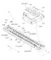
図1には、基板対基板コネクタ10を構成するレセプタクルコネクタ20およびプラグコネクタ30が分離された状態(接続解除状態)で示されている。図中の矢印は、レセプタクルコネクタ20およびプラグコネクタ30の嵌合方向(接続方向)を示す。レセプタクルコネクタ20およびプラグコネクタ30は相互に着脱自在である。 FIG. 1 shows a state in which the
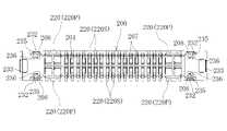
図2に示すように、レセプタクルコネクタ20は主として、ハウジング200と、所要数のコンタクト220と、補強金具230とを備える。 As shown in FIG. 2, the
ハウジング200は、電気絶縁性の合成樹脂を材料として射出成形等によって製造される。合成樹脂材料としては、例えば液晶ポリマー(LCP)やポリフェニレンサルファイド(PPS)、ポリブチレンテレフタレート(PBT)、ポリアミド(PA)等が挙げられるが、これらに限定されない。ハウジング200の材料は、無機フィラーや補強繊維等を含有していてもよい。 The
ハウジング200は、偏平な略直方体状の外形を有する。ハウジング200は、底壁201と底壁201の周縁から起立する周壁202とを有する。底壁201および周壁202は上面に開口する凹部203を区画する。 The
周壁202は、コンタクト220の配列ピッチ方向(ハウジング200の長手方向)Xに沿って延在し互いに対向する側壁部202aと、コンタクト220の配列ピッチ方向と直交する方向(ハウジングの短手方向)Yに沿って延在し互いに対向する端壁部202bとを有する。側壁部202aの内面には、各コンタクト220の外側部分を収容する平面視略T字形状の外側収容溝204が形成されている。外側収容溝204は、ハウジング200を高さ方向(厚み方向)に貫通している。外側収容溝204内にコンタクト220が挿入により組み付けられる場合、外側収容溝204はコンタクトに圧接する寸法を有することが好ましい。これに代えて、コンタクト220はハウジング200の射出成形時に一体化することもできる。すなわち、各コンタクト220をインサート体として図示しない金型に保持(セット)させ、ハウジング200の肉厚を形成する空間にハウジング200を形成する電気絶縁性の合成樹脂材料を射出(充填)することで、コンタクト220をハウジング200に固定(保持)してもよい。 The
ハウジング200はさらに、底壁201上に周壁202から離間して形成された平面視矩形の隆起部205を有する。これにより凹部203は環状空間として区画される。隆起部205の、側壁部202aに対向する側面には、コンタクト220の内側部分を収容する内側収容溝206が形成されている。内側収容溝206は、外側収容溝204に対向する位置にてハウジング200の高さ方向に延在する。内側収容溝206内には、湾曲状をした傾斜部分206a(図5(b),(c))が形成されている。傾斜部分206aはコンタクト220の内側接触部225の傾斜部分225aに沿うようにし、相手コネクタであるプラグコネクタ30の抜去時にコンタクト220の内側接触部225の持ち上がり防止やコンタクト220の変形防止等の動き(バックアップ)を調整する部分であり、繰り返し挿抜した際の安定した接続が得られるようにしたものである。内側収容溝206内の傾斜部分206aの形状・大きさは、コンタクト220の内側接触部225の傾斜部分225aに沿い、かつ、このような役割や接続安定性や加工性等を考慮して適宜設計する。 The
図1および図3に示すように、底壁201には、外側収容溝204および内側収容溝206と連通する開口207が形成されている。コンタクト220をハウジング200に挿入により組み付ける場合には、開口207を通じてコンタクト220を底面側から挿入することができる。 As shown in FIGS. 1 and 3, the
コンタクト220は、図4に示すように、導電性金属、好ましくは銅または銅合金からなり、幅の狭い信号用コンタクト220Sと、幅の広い電源用コンタクト220Pとを含む。しかし、全てのコンタクト220が信号用コンタクト220Sであってもよい。信号用コンタクト220Sと電源用コンタクト220Pの両方を設ける場合、両者は同じ形状および寸法でもよい。 As shown in FIG. 4, the
図5(b)および図5(c)に示すように、各コンタクト220(220S,220P)は、基板に実装される接続部221と、接続部221からハウジング200の高さ方向に沿って延び外側収容溝204に保持される被保持部222と、被保持部222の上端から隆起部205側に延出する延出部223と、隆起部205へ向けて凸に湾曲する外側接触部224と、該外側接触部224と対向し外側接触部224へ向けて凸に湾曲する内側接触部225と、断面U字形状を有し外側接触部224および内側接触部225間を連結する連結部226とを有する。コンタクト220は、プラグコネクタ30の後述するコンタクト320と接触できればよく、その構造は図示例に限定されず、例えば、唯一の接触部(224または225)を有するものでもよい。内側接触部225側に形成された傾斜部分225aは、ハウジング200の内側収容溝206内の傾斜部分206aと沿うよう(ほぼ対応する形状)にすることにより、相手コネクタであるプラグコネクタ30の抜去時にコンタクト220の内側接触部225の持ち上がり防止やコンタクト220の変形防止等の動き(バックアップ)を調整する部分であり、繰り返し挿抜した際の安定した接続が得られるようにしたものである。内側接触部分225に形成された傾斜部分225aの形状・大きさは、ハウジング200の内側収容溝206内の傾斜部分206aに沿い、かつ、このような役割や接続安定性や加工性等を考慮して適宜設計する。 As shown in FIGS. 5 (b) and 5 (c), each contact 220 (220S, 220P) extends from the
図1および図2に戻り、補強金具230は金属製、好ましくは銅や銅合金等の導電性金属からなり、ハウジング200の長手方向両端部を部分的に覆っている。これによりハウジング200の両端部は補強されている。補強金具230は、ハウジング200を基板に固定する固定タブとしても機能する。 Returning to FIGS. 1 and 2, the reinforcing metal fitting 230 is made of a metal, preferably a conductive metal such as copper or a copper alloy, and partially covers both ends in the longitudinal direction of the
図6に補強金具230を単体で示す。補強金具230はハウジング200の射出成形時にハウジング200と一体化される。すなわち、補強金具230をインサート体として図示しない金型に保持(セット)し、ハウジング200の肉厚を形成する空間にハウジング200の合成樹脂材料を射出(充填)することで、補強金具230はハウジング200に固定(保持)される。これに代えて、補強金具230はハウジング200の形成後にハウジング200に挿入(圧入)および/または接着により固定してもよい。 FIG. 6 shows the reinforcing metal fitting 230 as a single unit. The reinforcing metal fitting 230 is integrated with the
補強金具230は、主として、頂壁231と、ハウジング200の短手方向Yで対向する一対の垂下側壁232と、垂下端壁233と、垂下片234と、片持ち弾性片235と、接触片236とを備え、金属製板材から例えばスタンピング加工により所定形状、寸法にカットした中間片を曲げ加工することで形成される。 The reinforcing metal fitting 230 mainly includes a
頂壁231は、ハウジング200の長手方向端部において、周壁202の側壁部202aの上面および端壁部202bの上面(基板実装面の反対側の面)に沿って延在する平面視略C字形状をなす。頂壁231の対向内辺および後辺には、ハウジング200と係合する係合部231a,231bを形成することが好ましい。係合部231aは、ハウジング200と長手方向Xで係合して該長手方向Xでの相対移動を規制する。係合部231bは、ハウジング200と短手方向Yで係合して該短手方向Yでの相対移動を規制する。 The
垂下側壁232は、頂壁231の外側側縁から周壁202の側壁部202aの外面に沿って垂下し、その下端部において基板に実装、固定される。垂下端壁233は、頂壁231の後辺(外側の端縁)から周壁202の端壁部202bの外面に沿って垂下し、その下端部において基板に実装、固定される。垂下側壁232および垂下端壁233は、周壁202の外面と面一である。 The hanging
垂下片234は、頂壁231の内側の端縁から周壁202の端壁部202bの内面に沿って垂下し、垂下端壁233との間に該端壁部202bを挟持する。垂下片234は周壁202の内面と面一である。 The hanging
片持ち弾性片235は、各垂下側壁232の、長手方向Xで外側に位置する側縁から他方の垂下側壁232に向かって延びる垂直な延出壁237を介して該垂下側壁232に一体に連結されている。片持ち弾性片235は、コンタクト220の配列ピッチ方向(ハウジング200の長手方向X)に沿って延在する。図1に示すように、片持ち弾性片235は、所定のばね長が得られるようその自由端側端部がハウジング200の樹脂材料から露出し、残余部分がハウジング200の樹脂材料内に埋没されている。片持ち弾性片235の自由端側端部を露出させるため、ハウジング200の底壁201には、片持ち弾性片235の自由端側端部の周辺に貫通孔208(図2および図3参照)が形成されている。片持ち弾性片235はその全体がハウジング200の樹脂材料から露出するものでもよい。補強金具230はさらに、片持ち弾性片235の自由端側端部から延出し、レセプタクルコネクタ20とプラグコネクタ30との嵌合時にプラグコネクタ30と接触する接触片236を有する。接触片236が所定のばね長を有する片持ち弾性片235に支持されているので、レセプタクルコネクタ20が低背化された場合においても、十分なばね長を確保して接触片236をプラグコネクタ30に安定して接触させることができる。 The cantilever
好適な態様では、接触片236は、ハウジング200の高さ方向、つまり片持ち弾性片235の自由端側端部から頂壁231に向かって延出している。 In a preferred embodiment, the
より好適な態様では、レセプタクルコネクタ20に対するプラグコネクタ30の嵌合方向で見て、接触片236の先端部は、頂壁231によって覆隠されている。これにより、プラグコネクタ30との背面嵌合等の不適切な嵌合は回避される。 In a more preferred embodiment, the tip of the
より好適な態様では、接触片236は、その基端部と先端部との間に内向き凸、すなわち凹部203の内側へ向けて突出した湾曲部236aを有する。これにより、短手方向Yで対向する接触片236間へのプラグコネクタ30の挿入・抜去を円滑に行うことができる。 In a more preferred embodiment, the
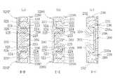
図7および図8に、レセプタクルコネクタ20とプラグコネクタ30との嵌合状態を示す。図7は嵌合状態にあるレセプタクルコネクタ20およびプラグコネクタ30を、プラグコネクタ30の底面側(基板実装側)から見た平面図であり、図8(a)は図7中のD-D線に沿う断面図であり、図8(b)は図7中のE-E線に沿う断面図であり、図8(c)は図7中のF-F線に沿う断面図である。 7 and 8 show the fitted state of the
図7および図8に加えて図1に示すように、プラグコネクタ30は、主として電気絶縁性の合成樹脂からなるブロック300と、ブロック300に保持された所要数のコンタクト320と、ブロック300の長手方向端部に設けられた補強金具330とを備える。 As shown in FIG. 1 in addition to FIGS. 7 and 8, the
ブロック300の材料としては、例えば液晶ポリマー(LCP)やポリフェニレンサルファイド(PPS)、ポリブチレンテレフタレート(PBT)、ポリアミド(PA)等が挙げられるが、これらに限定されない。ブロック300の材料は、無機フィラーや補強繊維等を含有していてもよい。ブロック300は、ハウジング200の凹部203に適合する形状を有し、隆起部205を収容する溝305(図1)を有する。 Examples of the material of the
コンタクト320は、図1、図7および図8(a),(b)に示すように、幅の狭い信号用コンタクト320Sと、幅の広い電源用コンタクト320Pとを含む。しかし、全てのコンタクト320が信号用コンタクト320Sであってもよい。信号用コンタクト320Sと電源用コンタクト320Pの両方を設ける場合、両者は同じ形状および寸法でもよい。コンタクト320は導電性金属、例えば銅または銅合金からなる。各コンタクト320は、基板に実装される接続部321と、接続部321からブロック300の高さ方向に起立しコンタクト220の内側接触部225と接触する内側接触部325と、該内側接触部325と対向しコンタクト220の外側接触部224と接触する外側接触部324と、内側接触部325および外側接触部324を連結する連結部326とを有する。コンタクト320は、レセプタクルコネクタ20のコンタクト220と接触できればよく、その構造は図示例に限定されず、例えば、唯一の接触部(324または325)を有するものでもよい。 As shown in FIGS. 1, 7 and 8 (a) and 8 (b), the
補強金具330は、ブロック300の射出成形時に一体化される。すなわち、補強金具330をインサート体として図示しない金型に保持(セット)し、ブロック300の肉厚を形成する空間にブロック300の合成樹脂材料を射出(充填)することで、補強金具330はブロック300に固定(保持)される。これに代えて、補強金具330はブロック300の形成後にブロック300に挿入(圧入)および/または接着により固定してもよい。 The reinforcing metal fitting 330 is integrated at the time of injection molding of the
補強金具330は、好ましくは銅または銅合金等の導電性金属からなる板材を所定形状、寸法にカットした中間片を曲げ加工することで形成される。補強金具330は、図1に示すように、ブロック300の長手方向端部を上面、左右の側面および端面の4面で覆うように形成される。補強金具330はまた、底面側でブロック300から突出し基板に実装、固定される接続片330aを有する。 The reinforcing metal fitting 330 is preferably formed by bending an intermediate piece obtained by cutting a plate material made of a conductive metal such as copper or a copper alloy into a predetermined shape and size. As shown in FIG. 1, the reinforcing metal fitting 330 is formed so as to cover the longitudinal end portion of the
図8(a)では、レセプタクルコネクタ20の幅広のコンタクト220Pの外側接触部224および内側接触部225間に、プラグコネクタ30の幅広のコンタクト320Pが入り込んで2点接触していることが視認される。また、レセプタクルコネクタ20の隆起部205がプラグコネクタ30の溝305内に挿入されていることが視認される。 In FIG. 8A, it can be visually recognized that the
同様に、図8(b)では、レセプタクルコネクタ20の幅狭のコンタクト220Sの外側接触部224および内側接触部225間に、プラグコネクタ30の幅狭のコンタクト320Sが入り込んで2点接触していることが視認される。また、レセプタクルコネクタ20の隆起部205がプラグコネクタ30の溝305内に挿入されていることが視認される。 Similarly, in FIG. 8B, the
図8(c)では、レセプタクルコネクタ20の凹部203内にプラグコネクタ30のブロック300が挿入され、プラグコネクタ30の補強金具330がレセプタクルコネクタ20の補強金具230の片持ち弾性片235に支持された接触片236と接触している様子が視認される。 In FIG. 8C, the
次に図9を参照し、本発明の実施形態のレセプタクルコネクタ20に適用される補強金具230の変形例を説明する。図6を参照して説明した補強金具230では、片持ち弾性片235が、垂下側壁232の、長手方向Xで外側に位置する側縁から対向する他方の垂下側壁232に向かって延びる垂直な延出壁237を介して該垂下側壁232に一体に連結されているが、本変形例では、図9に示すように、片持ち弾性片235は、垂下側壁232の、長手方向Xで外側寄り部分の下端から対向する他方の垂下側壁232に向かって延びる水平な延出壁237を介して該垂下側壁232に一体的に連結されている。 Next, with reference to FIG. 9, a modified example of the reinforcing metal fitting 230 applied to the
片持ち弾性片235が、コンタクト220の配列ピッチ方向(ハウジング200の長手方向X)に沿って延在する点は図6の補強金具230と同じである。片持ち弾性片235は、所定のばね長が得られるようその自由端端部側がハウジング200の樹脂材料から露出し、残余部分がハウジング200の樹脂材料内に埋没されているが、片持ち弾性片235の全体をハウジング200の樹脂材料から露出させてもよい。補強金具230はさらに、片持ち弾性片235の自由端側端部から延出し、レセプタクルコネクタ20とプラグコネクタ30との嵌合時にプラグコネクタ30と接触する接触片236を有する。接触片236が所定のばね長を有する片持ち弾性片235に支持されているので、レセプタクルコネクタ20が低背化された場合においても、十分なばね長を確保して接触片236をプラグコネクタ30に安定して接触させることができる。 The point that the cantilever
本変形例においても、接触片236は、ハウジング200の高さ方向、すなわち片持ち弾性片235の自由端側端部から頂壁231に向かって延在している。 Also in this modification, the
また、レセプタクルコネクタ20に対するプラグコネクタ30の嵌合方向で見て、接触片236の先端部は、頂壁231によって覆隠されていることが好ましく、これにより、プラグコネクタ30との背面嵌合等の不適切な嵌合は回避される。 Further, when viewed in the fitting direction of the
さらに、接触片236は、その基端部と先端部との間に内向き凸、すなわち凹部203の内側へ向けて突出した湾曲部236aを有することが好ましく、これにより、短手方Yで対向する接触片236間へのプラグコネクタ30の挿入・抜去を円滑に行うことができる。 Further, the
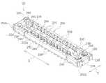
図10は、本発明の他の一実施形態のレセプタクルコネクタ20を示す上面側斜視図である。このレセプタクルコネクタ20も、先の実施形態におけるプラグコネクタ30と同様の図示しないプラグコネクタと嵌合することで基板間の電気的な接続を行う基板対基板コネクタを構成するものであり、そのプラグコネクタとレセプタクルコネクタ20とは相互に着脱自在である。 FIG. 10 is a top perspective view showing a
図10に示すように、レセプタクルコネクタ20は主として、ハウジング200と、所要数のコンタクト220と、補強金具230とを備える。 As shown in FIG. 10, the
ハウジング200は、電気絶縁性の合成樹脂を材料として射出成形等によって製造される。合成樹脂材料としては、例えば液晶ポリマー(LCP)やポリフェニレンサルファイド(PPS)、ポリブチレンテレフタレート(PBT)、ポリアミド(PA)等が挙げられるが、これらに限定されない。ハウジング200の材料は、無機フィラーや補強繊維等を含有していてもよい。 The
ハウジング200は、偏平な略直方体状の外形を有する。ハウジング200は、底壁201と底壁201の周縁から起立する周壁202とを有する。底壁201および周壁202は上面に開口する凹部203を区画する。 The
周壁202は、コンタクト220の配列ピッチ方向(ハウジング200の長手方向)Xに沿って延在し互いに対向する側壁部202aと、コンタクト220の配列ピッチ方向と直交する方向(ハウジングの短手方向)Yに沿って延在し互いに対向する端壁部202bとを有する。側壁部202aの内面には、各コンタクト220の外側部分を収容する平面視略T字形状の外側収容溝204が形成されている。外側収容溝204は、ハウジング200を高さ方向(厚み方向)に貫通している。外側収容溝204内にコンタクト220が挿入により組み付けられる場合、外側収容溝204はコンタクトに圧接する寸法を有することが好ましい。 The
これに代えて、コンタクト220はハウジング200の射出成形時に一体化することもできる。すなわち、各コンタクト220をインサート体として図示しない金型に保持(セット)させ、ハウジング200の肉厚を形成する空間にハウジング200を形成する電気絶縁性の合成樹脂材料を射出(充填)することで、コンタクト220をハウジング200に固定(保持)してもよい。 Alternatively, the
ハウジング200はさらに、底壁201上に周壁202から離間して形成された平面視矩形の隆起部205を有する。これにより凹部203は環状空間として区画される。隆起部205の、側壁部202aに対向する側面には、コンタクト220の内側部分を収容する内側収容溝206が形成されている。内側収容溝206は、外側収容溝204に対向する位置にてハウジング200の高さ方向に延在する。内側収容溝206内には、湾曲状をした傾斜部分206a(図12(c))が形成されている。 The
傾斜部分206aはコンタクト220の内側接触部225の傾斜部分225aに沿うようにし、相手コネクタであるプラグコネクタの抜去時にコンタクト220の内側接触部225の持ち上がり防止やコンタクト220の変形防止等の動き(バックアップ)を調整する部分であり、繰り返し挿抜した際の安定した接続が得られるようにしたものである。内側収容溝206内の傾斜部分206aの形状・大きさは、コンタクト220の内側接触部225の傾斜部分225aに沿い、かつ、このような役割や接続安定性や加工性等を考慮して適宜設計する。 The
図12(c)に示すように、底壁201には、外側収容溝204および内側収容溝206と連通する開口207が形成されている。コンタクト220をハウジング200に挿入により組み付ける場合には、開口207を通じてコンタクト220を底面側から挿入することができる。 As shown in FIG. 12 (c), the
コンタクト220は、先の実施形態のものと同様、導電性金属、好ましくは銅または銅合金からなり、この実施形態では、全てのコンタクト220が同じ形状および寸法を有している。 The
図12(c)に示すように、各コンタクト220は、基板に実装される接続部221と、接続部221からハウジング200の高さ方向に沿って延び外側収容溝204に保持される被保持部222と、被保持部222の上端から隆起部205側に延出する延出部223と、隆起部205へ向けて凸に湾曲する外側接触部224と、該外側接触部224と対向し外側接触部224へ向けて凸に湾曲する内側接触部225と、断面U字形状を有し外側接触部224および内側接触部225間を連結する連結部226とを有する。コンタクト220は、図1に示す如きプラグコネクタのコンタクトと接触できればよく、その構造は図示例に限定されず、例えば、唯一の接触部(224または225)を有するものでもよい。 As shown in FIG. 12 (c), each
内側接触部225側に形成された傾斜部分225aは、ハウジング200の内側収容溝206内の傾斜部分206aと沿うよう(ほぼ対応する形状)にすることにより、相手コネクタであるプラグコネクタの抜去時にコンタクト220の内側接触部225の持ち上がり防止やコンタクト220の変形防止等の動き(バックアップ)を調整する部分であり、繰り返し挿抜した際の安定した接続が得られるようにしたものである。内側接触部分225に形成された傾斜部分225aの形状・大きさは、ハウジング200の内側収容溝206内の傾斜部分206aに沿い、かつ、このような役割や接続安定性や加工性等を考慮して適宜設計する。 The
この実施形態における各コンタクト220の内側接触部225の傾斜部分225aは、先の実施形態における内側接触部225の先端部側に配置された傾斜部分225aと異なって、連結部226に連なる内側接触部225の基部側に配置されており、このようにして、相手コネクタであるプラグコネクタの抜去時にハウジング200の内側収容溝206内の傾斜部分206aで傾斜部分225aを確実にバックアップすることにより、コンタクト220の内側接触部225の持ち上がりやコンタクト220の変形を防止して、プラグコネクタを繰り返し挿抜した際の安定した接続が得られるようにしている。 The
図10に戻り、補強金具230は金属製、好ましくは銅や銅合金等の導電性金属からなり、ハウジング200の長手方向両端部を部分的に覆っている。これによりハウジング200の両端部は補強されている。補強金具230は、ハウジング200を基板に固定する固定タブとしても機能する。 Returning to FIG. 10, the reinforcing metal fitting 230 is made of a metal, preferably a conductive metal such as copper or a copper alloy, and partially covers both ends in the longitudinal direction of the
図13に補強金具230を単体で示す。補強金具230はハウジング200の射出成形時にハウジング200と一体化される。すなわち、補強金具230をインサート体として図示しない金型に保持(セット)し、ハウジング200の肉厚を形成する空間にハウジング200の合成樹脂材料を射出(充填)することで、補強金具230はハウジング200に固定(保持)される。これに代えて、補強金具230はハウジング200の形成後にハウジング200に挿入(圧入)および/または接着により固定してもよい。 FIG. 13 shows the reinforcing metal fitting 230 as a single unit. The reinforcing metal fitting 230 is integrated with the
補強金具230は、主として、頂壁231と、ハウジング200の短手方向Yで対向する一対の垂下側壁232と、垂下端壁233と、垂下片234と、片持ち弾性片235と、接触片236とを備え、金属製板材から例えばスタンピング加工により所定形状、寸法にカットした中間片を曲げ加工することで形成される。 The reinforcing metal fitting 230 mainly includes a
頂壁231は、ハウジング200の長手方向端部において、周壁202の側壁部202aの上面および端壁部202bの上面(基板実装面の反対側の面)に沿って延在する平面視略C字形状をなす。頂壁231の対向内辺および後辺には、ハウジング200と係合する係合部231a,231bを形成することが好ましい。係合部231aは、ハウジング200と長手方向Xで係合して該長手方向Xでの相対移動を規制する。係合部231bは、ハウジング200と短手方向Yで係合して該短手方向Yでの相対移動を規制する。 The
垂下側壁232は、頂壁231の外側側縁から周壁202の側壁部202aの外面に沿って垂下し、その下端部において基板に実装、固定される。垂下端壁233は、頂壁231の後辺(外側の端縁)から周壁202の端壁部202bの外面に沿って垂下し、その下端部において基板に実装、固定される。垂下側壁232および垂下端壁233は、周壁202の外面と面一である。 The hanging
垂下片234は、頂壁231の内側の端縁から周壁202の端壁部202bの内面に沿って垂下し、垂下端壁233との間に該端壁部202bを挟持する。垂下片234の先端からは底部片238が水平に延在し、その底部片238の先端からは垂下片234と対向する対向片239が立ち上がり、これら垂下片234と底部片238と対向片239とは全体として溝形をなし、その対向片239の先端からは端部片240が水平に延在する。図10に示すように、垂下片234は周壁202の端壁部202bの内面と面一であり、対向片239はハウジング200の隆起部205の、端壁部202bの内面と対向する端面と面一であり、図12(a)に示すように、底部片238はハウジング200の底壁201の内面と面一であり、図12(b)に示すように、端部片240はハウジング200の隆起部205の上面と面一である。 The hanging
片持ち弾性片235は、各垂下側壁232の、長手方向Xで外側に位置する側縁から他方の垂下側壁232に向かって延びる垂直な延出壁237を介して該垂下側壁232に一体に連結されている。片持ち弾性片235は、コンタクト220の配列ピッチ方向(ハウジング200の長手方向X)に沿って延在する。図10および図12(a)に示すように、片持ち弾性片235は、所定のばね長が得られるようその自由端側端部がハウジング200の樹脂材料から露出し、残余部分がハウジング200の樹脂材料内に埋没されている。片持ち弾性片235の自由端側端部を露出させるため、ハウジング200の底壁201には、片持ち弾性片235の自由端側端部の周辺に貫通孔208(図12(a)参照)が形成されている。 The cantilever
片持ち弾性片235はその全体がハウジング200の樹脂材料から露出するものでもよい。補強金具230はさらに、片持ち弾性片235の自由端側端部から延出し、レセプタクルコネクタ20とプラグコネクタとの嵌合時にプラグコネクタと接触する接触片236を有する。接触片236が所定のばね長を有する片持ち弾性片235に支持されているので、レセプタクルコネクタ20が低背化された場合においても、十分なばね長を確保して接触片236をプラグコネクタに安定して接触させることができる。 The cantilever
好適な態様では、接触片236は、ハウジング200の高さ方向、つまり片持ち弾性片235の自由端側端部から頂壁231に向かって延出している。より好適な態様では、レセプタクルコネクタ20に対するプラグコネクタ30の嵌合方向で見て、接触片236の先端部は、頂壁231によって覆隠されている。これにより、プラグコネクタ30との背面嵌合等の不適切な嵌合は回避される。 In a preferred embodiment, the
より好適な態様では、接触片236は、その基端部と先端部との間に内向き凸、すなわち凹部203の内側へ向けて突出した湾曲部236aを有する。これにより、短手方向Yで対向する接触片236間へのプラグコネクタ30の挿入・抜去を円滑に行うことができる。 In a more preferred embodiment, the
この実施形態のレセプタクルコネクタ20によっても、先の実施形態のレセプタクルコネクタ20と同様の作用効果を得ることができる。 The
本発明によれば、コネクタを低背化してもなお、補強金具の接触片を介して相手方コネクタとの良好な接触が得られるレセプタクルコネクタを提供することが可能となる。 According to the present invention, it is possible to provide a receptacle connector that can obtain good contact with a mating connector via a contact piece of a reinforcing metal fitting even if the height of the connector is reduced.
10 基板対基板コネクタ
20 レセプタクルコネクタ
200 ハウジング
201 底壁
202 周壁
202a 側壁部
202b 端壁部
203 凹部
204 外側収容溝
205 隆起部
206 内側収容溝
207 開口
208 貫通孔
220 コンタクト
220P 電源用コンタクト
220S 信号用コンタクト
221 接続部
222 被保持部
223 延出部
224 外側接触部
225 内側接触部
226 連結部
230 補強金具
231 頂壁
231a,231b 係合部
232 垂下側壁
233 垂下端壁
234 垂下片
235 片持ち弾性片
236 接触片
236a 湾曲部
237 延出壁
238 底部片
239 対向片
240 端部片10 Board-to-
Claims (5)
Translated fromJapanese基板実装面の反対側に開口し前記プラグコネクタを受容する凹部が形成されたハウジングと、
前記ハウジングの両端部間に配列された所要数のコンタクトと、
前記ハウジングの前記両端部にそれぞれ設けられた補強金具と、を備え、
前記補強金具は、前記コンタクトの配列ピッチ方向に沿って延在する片持ち弾性片と、該片持ち弾性片の自由端側端部から延出し、前記レセプタクルコネクタと前記プラグコネクタとの嵌合時に該プラグコネクタと接触する接触片とを有するとともに、前記ハウジングの、前記基板実装面の反対側の面に沿って形成された頂壁を有し、
前記レセプタクルコネクタに対する前記プラグコネクタの嵌合方向で見て、前記接触片の先端部は前記頂壁によって覆隠されていることを特徴とするレセプタクルコネクタ。It is a receptacle connector in a board-to-board connector that electrically connects both boards by fitting a receptacle connector mounted on one board and a plug connector mounted on the other board.
A housing having a recess opened on the opposite side of the board mounting surface to receive the plug connector, and a housing.
With the required number of contacts arranged between both ends of the housing,
Reinforcing metal fittings provided at both ends of the housing are provided.
The reinforcing metal fitting extends from the cantilever elastic piece extending along the arrangement pitch direction of the contact and the free end side end portion of the cantilever elastic piece, and when the receptacle connector and the plug connector are fitted to each other, the reinforcing metal fitting extends from the free end side end portion of the cantilever elastic piece. It has a contact piece in contact with the plug connector andhas a top wall formed along the opposite surface of the board mounting surface of the housing.
A receptacle connector characterizedin that the tip end portion of the contact piece is covered by the top wall when viewed in the fitting direction of the plug connector with respect to the receptacle connector.
Applications Claiming Priority (3)
| Application Number | Priority Date | Filing Date | Title |
|---|---|---|---|
| JP2018175189 | 2018-09-19 | ||
| JP2018175189 | 2018-09-19 | ||
| PCT/JP2019/020569WO2020059210A1 (en) | 2018-09-19 | 2019-05-24 | Receptacle connector |
Publications (2)
| Publication Number | Publication Date |
|---|---|
| JPWO2020059210A1 JPWO2020059210A1 (en) | 2021-08-30 |
| JP7055893B2true JP7055893B2 (en) | 2022-04-18 |
Family
ID=69886867
Family Applications (1)
| Application Number | Title | Priority Date | Filing Date |
|---|---|---|---|
| JP2020547952AActiveJP7055893B2 (en) | 2018-09-19 | 2019-05-24 | Receptacle connector |
Country Status (4)
| Country | Link |
|---|---|
| US (1) | US11777253B2 (en) |
| JP (1) | JP7055893B2 (en) |
| CN (1) | CN112740484B (en) |
| WO (1) | WO2020059210A1 (en) |
Families Citing this family (8)
| Publication number | Priority date | Publication date | Assignee | Title |
|---|---|---|---|---|
| JP7055893B2 (en)* | 2018-09-19 | 2022-04-18 | 株式会社フジクラ | Receptacle connector |
| JP7458224B2 (en)* | 2020-03-27 | 2024-03-29 | 日本航空電子工業株式会社 | board to board connector |
| CN215119330U (en)* | 2020-05-13 | 2021-12-10 | 日本航空电子工业株式会社 | Connector |
| JP7417481B2 (en)* | 2020-06-29 | 2024-01-18 | 日本航空電子工業株式会社 | connector |
| CN112636036A (en)* | 2020-12-28 | 2021-04-09 | 昆山嘉华电子有限公司 | Board-to-board connector |
| JP7562457B2 (en)* | 2021-03-17 | 2024-10-07 | 京セラ株式会社 | Connectors and Electronic Devices |
| JP2023092756A (en)* | 2021-12-22 | 2023-07-04 | 日本航空電子工業株式会社 | connector |
| WO2025004413A1 (en)* | 2023-06-26 | 2025-01-02 | 日本航空電子工業株式会社 | Connector and connector device |
Citations (3)
| Publication number | Priority date | Publication date | Assignee | Title |
|---|---|---|---|---|
| JP2013206771A (en) | 2012-03-29 | 2013-10-07 | Hirose Electric Co Ltd | Electric connector assembly and receptacle connector |
| JP2015135816A (en) | 2014-01-17 | 2015-07-27 | タイコ エレクトロニクス (シャンハイ) カンパニー リミテッド | Terminal, electrical connector, and electrical connector assembly |
| JP2015185541A (en) | 2014-03-20 | 2015-10-22 | 日本航空電子工業株式会社 | connector assembly |
Family Cites Families (6)
| Publication number | Priority date | Publication date | Assignee | Title |
|---|---|---|---|---|
| JP2013101909A (en)* | 2011-10-14 | 2013-05-23 | Molex Inc | Connector |
| CN103367978B (en) | 2012-03-29 | 2016-04-20 | 广濑电机株式会社 | Electric connector assembly and plug connector |
| KR20160046173A (en)* | 2014-10-20 | 2016-04-28 | 엘에스엠트론 주식회사 | Receptacle connector and Connector assembly for board-to-board including the same |
| JP6404248B2 (en) | 2016-02-15 | 2018-10-10 | モレックス エルエルシー | connector |
| CN107658592B (en)* | 2016-07-26 | 2020-05-12 | 株式会社藤仓 | Socket connector and manufacturing method thereof |
| JP7055893B2 (en)* | 2018-09-19 | 2022-04-18 | 株式会社フジクラ | Receptacle connector |
- 2019
- 2019-05-24JPJP2020547952Apatent/JP7055893B2/enactiveActive
- 2019-05-24WOPCT/JP2019/020569patent/WO2020059210A1/ennot_activeCeased
- 2019-05-24USUS17/278,247patent/US11777253B2/enactiveActive
- 2019-05-24CNCN201980061153.8Apatent/CN112740484B/enactiveActive
Patent Citations (3)
| Publication number | Priority date | Publication date | Assignee | Title |
|---|---|---|---|---|
| JP2013206771A (en) | 2012-03-29 | 2013-10-07 | Hirose Electric Co Ltd | Electric connector assembly and receptacle connector |
| JP2015135816A (en) | 2014-01-17 | 2015-07-27 | タイコ エレクトロニクス (シャンハイ) カンパニー リミテッド | Terminal, electrical connector, and electrical connector assembly |
| JP2015185541A (en) | 2014-03-20 | 2015-10-22 | 日本航空電子工業株式会社 | connector assembly |
Also Published As
| Publication number | Publication date |
|---|---|
| WO2020059210A1 (en) | 2020-03-26 |
| US20210359466A1 (en) | 2021-11-18 |
| JPWO2020059210A1 (en) | 2021-08-30 |
| CN112740484B (en) | 2022-08-30 |
| CN112740484A (en) | 2021-04-30 |
| US11777253B2 (en) | 2023-10-03 |
Similar Documents
| Publication | Publication Date | Title |
|---|---|---|
| JP7055893B2 (en) | Receptacle connector | |
| CN112335137B (en) | Electrical connector | |
| CN106058518B (en) | Circuit board electrical connector | |
| US11233346B2 (en) | Board-to-board connector | |
| CN104934772B (en) | Connector assembly | |
| JP6385875B2 (en) | Circuit board electrical connector | |
| CN102646884B (en) | Electric connector | |
| JP6823195B2 (en) | Electrical connector | |
| JP7266513B2 (en) | receptacle connector | |
| JP2018170296A (en) | Circuit board electrical connector | |
| JP6860996B2 (en) | Regulators for electrical connectors for circuit boards | |
| JP2013016410A (en) | Electric connector | |
| JP6817477B2 (en) | Electrical connector for circuit board | |
| CN109586063B (en) | Connector for substrate and combination thereof | |
| JP5444284B2 (en) | Electrical connector | |
| KR102845338B1 (en) | Electric connector for circuit board and electric connector assembly | |
| JP5587714B2 (en) | Shield case, connector and electronic equipment | |
| KR102674178B1 (en) | Electrical connector and manufacturing method thereof | |
| JP6574470B2 (en) | Circuit board electrical connector | |
| JP6937400B2 (en) | connector | |
| JP2019029107A (en) | Electric connector | |
| CN112018535A (en) | Electric connector assembly | |
| KR20170045627A (en) | Board to board connector | |
| CN212085268U (en) | Board-to-board connector | |
| JP2016042489A (en) | Electrical connector |
Legal Events
| Date | Code | Title | Description |
|---|---|---|---|
| A621 | Written request for application examination | Free format text:JAPANESE INTERMEDIATE CODE: A621 Effective date:20210107 | |
| A131 | Notification of reasons for refusal | Free format text:JAPANESE INTERMEDIATE CODE: A131 Effective date:20211019 | |
| A521 | Request for written amendment filed | Free format text:JAPANESE INTERMEDIATE CODE: A523 Effective date:20211216 | |
| TRDD | Decision of grant or rejection written | ||
| A01 | Written decision to grant a patent or to grant a registration (utility model) | Free format text:JAPANESE INTERMEDIATE CODE: A01 Effective date:20220322 | |
| A61 | First payment of annual fees (during grant procedure) | Free format text:JAPANESE INTERMEDIATE CODE: A61 Effective date:20220406 | |
| R151 | Written notification of patent or utility model registration | Ref document number:7055893 Country of ref document:JP Free format text:JAPANESE INTERMEDIATE CODE: R151 | |
| R250 | Receipt of annual fees | Free format text:JAPANESE INTERMEDIATE CODE: R250 |