JP7055872B2 - Computer-enhanced information processing methods, programs, medical image analysis systems, and radiation therapy treatment systems for 2D / 3D image registration. - Google Patents
Computer-enhanced information processing methods, programs, medical image analysis systems, and radiation therapy treatment systems for 2D / 3D image registration.Download PDFInfo
- Publication number
- JP7055872B2 JP7055872B2JP2020529486AJP2020529486AJP7055872B2JP 7055872 B2JP7055872 B2JP 7055872B2JP 2020529486 AJP2020529486 AJP 2020529486AJP 2020529486 AJP2020529486 AJP 2020529486AJP 7055872 B2JP7055872 B2JP 7055872B2
- Authority
- JP
- Japan
- Prior art keywords
- dimensional
- image data
- image
- vascular
- computer
- Prior art date
- Legal status (The legal status is an assumption and is not a legal conclusion. Google has not performed a legal analysis and makes no representation as to the accuracy of the status listed.)
- Active
Links
Images


Classifications
- G—PHYSICS
- G06—COMPUTING OR CALCULATING; COUNTING
- G06T—IMAGE DATA PROCESSING OR GENERATION, IN GENERAL
- G06T7/00—Image analysis
- G06T7/10—Segmentation; Edge detection
- G06T7/168—Segmentation; Edge detection involving transform domain methods
- G—PHYSICS
- G06—COMPUTING OR CALCULATING; COUNTING
- G06T—IMAGE DATA PROCESSING OR GENERATION, IN GENERAL
- G06T5/00—Image enhancement or restoration
- G06T5/50—Image enhancement or restoration using two or more images, e.g. averaging or subtraction
- G—PHYSICS
- G06—COMPUTING OR CALCULATING; COUNTING
- G06T—IMAGE DATA PROCESSING OR GENERATION, IN GENERAL
- G06T7/00—Image analysis
- G06T7/10—Segmentation; Edge detection
- G06T7/11—Region-based segmentation
- G—PHYSICS
- G06—COMPUTING OR CALCULATING; COUNTING
- G06T—IMAGE DATA PROCESSING OR GENERATION, IN GENERAL
- G06T7/00—Image analysis
- G06T7/30—Determination of transform parameters for the alignment of images, i.e. image registration
- G—PHYSICS
- G06—COMPUTING OR CALCULATING; COUNTING
- G06T—IMAGE DATA PROCESSING OR GENERATION, IN GENERAL
- G06T2207/00—Indexing scheme for image analysis or image enhancement
- G06T2207/10—Image acquisition modality
- G06T2207/10072—Tomographic images
- G—PHYSICS
- G06—COMPUTING OR CALCULATING; COUNTING
- G06T—IMAGE DATA PROCESSING OR GENERATION, IN GENERAL
- G06T2207/00—Indexing scheme for image analysis or image enhancement
- G06T2207/10—Image acquisition modality
- G06T2207/10072—Tomographic images
- G06T2207/10088—Magnetic resonance imaging [MRI]
- G—PHYSICS
- G06—COMPUTING OR CALCULATING; COUNTING
- G06T—IMAGE DATA PROCESSING OR GENERATION, IN GENERAL
- G06T2207/00—Indexing scheme for image analysis or image enhancement
- G06T2207/10—Image acquisition modality
- G06T2207/10116—X-ray image
- G—PHYSICS
- G06—COMPUTING OR CALCULATING; COUNTING
- G06T—IMAGE DATA PROCESSING OR GENERATION, IN GENERAL
- G06T2207/00—Indexing scheme for image analysis or image enhancement
- G06T2207/10—Image acquisition modality
- G06T2207/10116—X-ray image
- G06T2207/10124—Digitally reconstructed radiograph [DRR]
- G—PHYSICS
- G06—COMPUTING OR CALCULATING; COUNTING
- G06T—IMAGE DATA PROCESSING OR GENERATION, IN GENERAL
- G06T2207/00—Indexing scheme for image analysis or image enhancement
- G06T2207/30—Subject of image; Context of image processing
- G06T2207/30004—Biomedical image processing
- G06T2207/30016—Brain
- G—PHYSICS
- G06—COMPUTING OR CALCULATING; COUNTING
- G06T—IMAGE DATA PROCESSING OR GENERATION, IN GENERAL
- G06T2207/00—Indexing scheme for image analysis or image enhancement
- G06T2207/30—Subject of image; Context of image processing
- G06T2207/30004—Biomedical image processing
- G06T2207/30101—Blood vessel; Artery; Vein; Vascular
Landscapes
- Engineering & Computer Science (AREA)
- Physics & Mathematics (AREA)
- General Physics & Mathematics (AREA)
- Theoretical Computer Science (AREA)
- Computer Vision & Pattern Recognition (AREA)
- Apparatus For Radiation Diagnosis (AREA)
- Magnetic Resonance Imaging Apparatus (AREA)
- Image Processing (AREA)
Description
Translated fromJapanese 発明の分野
本発明は、解剖学的構造の血管構造の血管奇形の三次元表示の計算、ならびに、上記計算のための二次元および三次元医用画像のレジストレーションに関する。特に、本発明は、二次元/三次元画像コレジストレーションまたは融合の、コンピュータによって実現される医用方法、対応するコンピュータプログラム、このようなプログラムを格納する非一時的なプログラム記憶媒体、プログラムを実行するためのコンピュータ、ならびに医用画像分析システムおよび放射線療法治療システムに関する。INDUSTRIAL APPLICABILITY The present invention relates to the calculation of a three-dimensional representation of a vascular malformation of an anatomical vascular structure and the registration of two-dimensional and three-dimensional medical images for the above calculation. In particular, the invention implements a computer-implemented medical method of two-dimensional / three-dimensional image registration or fusion, a corresponding computer program, a non-temporary program storage medium for storing such a program, a program. Computers for, as well as medical image analysis systems and radiotherapy treatment systems.
技術背景
動静脈奇形(AVM)は、典型的には毛細管系を迂回する動脈と静脈との間の異常な接続である。血管異常または奇形は、それが中枢神経系で起こる(通常、脳動静脈奇形)ことで広く知られているが、たとえば人間の脳の血管系のような人体のいかなる場所でも起こり得る。Technical Background Arteriovenous malformations (AVMs) are typically abnormal connections between arteries and veins that bypass the capillary system. Vascular abnormalities or malformations are widely known to occur in the central nervous system (usually cerebral arteriovenous malformations), but can occur anywhere in the human body, such as the vascular system of the human brain.
多くのAVMは、無症候性であるが、激痛または出血を生じさせたり、他の深刻な医学的問題につながる可能性がある。特に、AVMが人間の脳の領域で発生した場合、このようなAVMを手術、放射線療法または放射線手術治療で治療する医師(たとえば、外科医または放射線療法士)に対して、患者の脳における血管奇形が三次元でどのように見えるかおよびそれがどこに位置しているかについての正確かつ信頼できる情報を提供することが最も重要である。特に、血管奇形の形状、ならびに、奇形への動脈流入構造および奇形からの静脈流出構造の位置が、手術または放射線療法/放射線手術治療の成功率にとって決定的に重要である。 Many AVMs are asymptomatic, but can cause severe pain or bleeding and can lead to other serious medical problems. Especially when AVM occurs in areas of the human brain, vascular malformations in the patient's brain are directed to a doctor (eg, a surgeon or radiation therapist) who treats such AVM with surgery, radiation therapy or radiation therapy. It is of utmost importance to provide accurate and reliable information about what looks like in three dimensions and where it is located. In particular, the shape of the vascular malformation, as well as the location of the arterial influx structure into the malformation and the venous outflow structure from the malformation, are critical to the success rate of surgery or radiation therapy / radiation therapy.
したがって、本発明の発明者等は、人間の脳における血管奇形(たとえば、動静脈奇形(AVM))の三次元表示を患者の医用画像から正確に計算する必要性を感じている。 Therefore, the inventors of the present invention feel the need to accurately calculate a three-dimensional display of a vascular malformation (eg, arteriovenous malformation (AVM)) in the human brain from a patient's medical image.
最近では、臨床診療において、ローカライザに基づくレジストレーションを使用して二次元および三次元画像が融合されている。血管奇形の正確な描写のために、位置特定が使用される。別のアプローチでは、ブレインラボ社の製品であるSmartbrush Angio 1.0は、血管セグメント化に基づくフレームレス二次元/三次元レジストレーションをサポートする。さらに、科学文献は、DRRまたはMIP画像に基づくフレームレス二次元/三次元レジストレーションを開示しているが、これは、解剖学的構造または奇形に注目するものではなく、不都合なことに、血管中心線または血管セグメント化に基づくフレームレスレジストレーションを使用するものではない。 Recently, in clinical practice, 2D and 3D images have been fused using localizer-based registrations. Positioning is used for accurate depiction of vascular malformations. In another approach, Brainlab's product Smartbrush Angio 1.0 supports frameless 2D / 3D registration based on vascular segmentation. In addition, scientific literature discloses frameless 2D / 3D registrations based on DRR or MIP images, which do not focus on anatomical structures or malformations and, unfortunately, blood vessels. It does not use frameless registration based on centerline or vascular segmentation.
二次元/三次元画像レジストレーションの既に公知の解決策は、以下の不利な点を伴う。第1に、治療計画のために追加画像を取得する必要があり、ローカライザフレームを患者の頭部に取り付けなければならないので、患者の負担、追加コストおよび治療までの時間が増加する。さらに、残念なことに、画像レジストレーションは、患者の頭蓋骨外で最も正確になる。また、血管セグメント化に基づく画像レジストレーションを使用する先行技術では、レジストレーション結果は、血管セグメント化の結果に依存する。さらに、上記の科学文献は研究文献に過ぎないため、臨床上の証拠が少ない。この科学文献は、奇形の部位に注目するものではなく、血管セグメント化または中心線抽出を必要とする。 Already known solutions for 2D / 3D image registration have the following disadvantages: First, additional images need to be acquired for treatment planning and the localizer frame must be attached to the patient's head, increasing the burden on the patient, additional costs and time to treatment. Moreover, unfortunately, image registration is most accurate outside the patient's skull. Also, in prior art using image registration based on vascular segmentation, the registration result depends on the result of vascular segmentation. Moreover, since the above scientific literature is nothing more than research literature, there is little clinical evidence. This scientific literature does not focus on the site of the malformation and requires vascular segmentation or centerline extraction.
したがって、本発明の発明者等は、患者の頭蓋骨内で適正に正確であり、血管セグメント化結果に依存せず、奇形の部位に注目することを可能にする、解剖学的構造に基づくフレームレス二次元/三次元画像レジストレーションの必要性を認識した。 Accordingly, the inventors of the present invention are frameless based on an anatomical structure that are adequately accurate within the skull of a patient, independent of vascular segmentation results, and allow attention to the site of the malformation. Recognized the need for 2D / 3D image registration.
以下の詳細な説明から明らかになるように、本発明の結果は、手術の計画に使用することができ、または放射線療法治療計画の計画にも使用することができる。 As will be apparent from the detailed description below, the results of the present invention can be used in the planning of surgery or also in the planning of radiotherapy treatment plans.
本発明は、たとえばVERO(登録商標)およびExacTrac(登録商標)(全てブレインラボ社の製品)などの画像誘導放射線療法のためのシステムに関連付けられた、たとえば頭蓋/脊柱定位放射線手術治療計画システムなどの放射線療法または放射線手術手順に使用することができる。また、この方法およびプログラムは、ブレインラボ社の製品である既存のSmartbrush Angioの補完および/または更新に使用されてもよい。 The present invention is associated with systems for image-guided radiotherapy, such as VERO® and ExacTrac® (all products of Brainlab), such as a cranial / stereotactic radiosurgery treatment planning system. Can be used for radiation therapy or radiosurgery procedures. The method and program may also be used to complement and / or update the existing Smartbrush Angio, a product of Brainlab.
本発明の局面、実施形態、実施例、および例示的なステップが以下に開示されている。本発明の異なる実施形態、実施例、および例示的な特徴は、技術的に好都合かつ実現可能である限りいかなる場合でも、本発明に従って組み合わせることができる。 Aspects, embodiments, examples, and exemplary steps of the invention are disclosed below. Different embodiments, examples, and exemplary features of the invention can be combined according to the invention wherever technically convenient and feasible.
さらに、本発明の一局面に関連して以下に記載されているいかなる特徴、要素および/またはステップも、本明細書に開示されている本発明のその他の局面に等しく適用される、ということが強調される。 Moreover, it is said that any feature, element and / or step described below in connection with one aspect of the invention applies equally to the other aspects of the invention disclosed herein. Be emphasized.
発明の例示的な簡単な説明
本発明は、血管奇形の三次元表示を計算する新たな方法を提供することによって、血管奇形を含む血管構造の二次元X線画像データの利点とこの血管構造の三次元画像データの利点とを組み合わせる。特に、二次元X線画像データの利点は、解像度が高いことであり、特に血管構造内の造影剤の分布の進展に関して、動脈と静脈との間の差異が医師が見てはっきり分かるほどであるという事実である。このような二次元X線の実施形態の例は、二次元DSA画像である。X線画像データのこれらの利点は、本発明の方法を適用すると、同一の血管構造の三次元画像データに転写される。それによって、この方法は、二次元X線画像データの上記の利点と三次元データセットの利点とを組み合わせる。すなわち、有利なことに、血管奇形(たとえば、AVM)を空間的な三次元の態様でユーザに対して表示して示すことができる。Illustrative Brief Description of the Invention The present invention provides a new method for calculating a three-dimensional representation of a vascular malformation, thereby providing the advantages of two-dimensional X-ray image data of the vascular structure, including the vascular malformation, and of this vascular structure. Combine with the advantages of 3D image data. In particular, the advantage of two-dimensional X-ray imaging data is the high resolution, so that the difference between arteries and veins can be clearly seen by the doctor, especially with respect to the evolution of the distribution of contrast agent in the vascular structure. The fact is that. An example of such a two-dimensional X-ray embodiment is a two-dimensional DSA image. These advantages of X-ray image data are transferred to three-dimensional image data of the same vascular structure by applying the method of the present invention. Thereby, this method combines the above advantages of 2D X-ray image data with the advantages of 3D datasets. That is, advantageously, the vascular malformation (eg, AVM) can be displayed and presented to the user in a spatial three-dimensional manner.
本発明は、血管奇形がたとえば人間の脳におけるAVMである場合に特に有効である。人間の脳に関して言えば、手術および/または放射線手術および/または放射線療法は非常にリスクが高いので、本発明のメリットおよび利点、すなわち血管奇形の三次元表示の精密な計算は、このような医療の文脈では非常に有効である。しかし、本開示から明らかになるように、本発明の方法は、AVMに限定されるものではなく、脳の領域に限定されるものではない。 The present invention is particularly useful when the vascular malformation is, for example, AVM in the human brain. As far as the human brain is concerned, surgery and / or radiation surgery and / or radiation therapy are at very high risk, so the advantages and benefits of the present invention, namely the precise calculation of the three-dimensional representation of vascular malformations, are such medical treatments. Very useful in the context of. However, as will be apparent from the present disclosure, the method of the invention is not limited to AVM and is not limited to brain regions.
以下に本発明の具体的特徴の簡単な説明が記載されているが、本発明をこのセクションに記載されている特徴または特徴の組み合わせのみに限定するように理解されるものではない。 A brief description of the specific features of the invention is provided below, but it is not understood to limit the invention to the features or combinations of features described in this section.
特に、二次元/三次元画像コレジストレーションの、コンピュータによって実現される医用方法が提示されている。二次元X線データは、血管構造内に血管奇形および造影剤を含む血管構造の医用画像である。たとえば、1つ以上の二次元デジタルサブトラクション血管造影(DSA)画像を二次元X線画像データとして使用することができる。さらに、この血管構造の三次元画像データが提供される。上記三次元画像データを生成するためにいくつかの異なる三次元画像化モダリティが使用されてもよい。たとえば、磁気共鳴(MR)画像データ、コンピュータトモグラフィ血管造影(CTA)画像データまたは三次元デジタルサブトラクション血管造影(三次元DSA)画像データが使用されてもよい。 In particular, computer-aided medical methods of 2D / 3D image registration have been presented. Two-dimensional X-ray data is a medical image of a vascular structure containing vascular malformations and contrast agents within the vascular structure. For example, one or more two-dimensional digital subtraction angiography (DSA) images can be used as two-dimensional X-ray image data. Further, three-dimensional image data of this vascular structure is provided. Several different 3D imaging modality may be used to generate the 3D image data. For example, magnetic resonance (MR) image data, computer tomography angiography (CTA) image data, or three-dimensional digital subtraction angiography (three-dimensional DSA) image data may be used.
このコンピュータによって実現される医用方法では、三次元画像データは、変換二次元画像データに変換される。いくつかの異なる変換可能性が当業者によって使用されてもよく、例として、三次元画像データを変換二次元画像データに変換するために最大値投影法(maximum intensity projection:MIP)および/またはデジタル再構成ラジオグラフィ(digitally reconstructed radiography:DRR)を使用する特定の具体的な実施形態について以下で詳細に説明する。 In the medical method realized by this computer, the 3D image data is converted into the converted 2D image data. Several different conversion possibilities may be used by those skilled in the art, for example, maximum intensity projection (MIP) and / or digital for converting 3D image data to converted 2D image data. Specific specific embodiments using digitally reconstructed radiography (DRR) are described in detail below.
さらに、二次元X線画像と、先に提供された三次元画像データから生じた変換二次元画像データとが重ね合わせられる。なお、本発明の文脈において、これらの二次元画像を「重ね合わせる」という表現は、ユーザのためにディスプレイ上でこれらのデータをグラフィカルに重ね合わせることを包含するだけでなく、計算上の方法でこれらのデータを重ね合わせることも包含する。二次元X線画像データと変換二次元画像データとを重ね合わせるステップがグラフィカルに実行されるのではなく純粋に計算上の方法で実行される実施形態では、これらの二次元画像データ間の類似性または対応関係の度合い/程度を計算することができる。二次元X線画像データと変換二次元画像データとを重ね合わせるプロセス中に、二次元X線画像データと変換二次元画像データとの間の対応関係(たとえば、類似性の画素単位の比較/判断)が計算される。それによって、二次元X線画像データと三次元画像データとの間のコレジストレーションがこの方法によって達成される。 Further, the two-dimensional X-ray image and the converted two-dimensional image data generated from the previously provided three-dimensional image data are superimposed. It should be noted that, in the context of the present invention, the expression "superimposing" these two-dimensional images not only includes graphically superimposing these data on a display for the user, but also in a computational manner. It also includes superimposing these data. Similarities between these 2D image data in embodiments where the step of superimposing the 2D X-ray image data and the transformed 2D image data is performed in a purely computational manner rather than graphically. Alternatively, the degree / degree of correspondence can be calculated. Correspondence between 2D X-ray image data and converted 2D image data during the process of superimposing 2D X-ray image data and converted 2D image data (eg, comparison / judgment of similarity on a pixel-by-pixel basis) ) Is calculated. Thereby, the registration between the two-dimensional X-ray image data and the three-dimensional image data is achieved by this method.
さらに、本発明のコンピュータによって実現される医用方法では、コレジストレーションがなされた二次元X線画像データにおいて血管奇形が判断される。その例示的な実施形態では、この血管奇形の判断は、たとえばコレジストレーションがなされた二次元X線画像データにおいて血管奇形を自動的に識別する画像分析アルゴリズムによって、純粋に自動的に行うことができる。しかし、これは、血管奇形の輪郭取りに関して以下でさらに詳細に説明するように、ユーザ入力に基づいて行うこともできる。判断された血管奇形に基づいて、血管奇形の三次元表示が計算される。この計算されたデータに基づく結果は、たとえば医師による手術の計画に使用することができ、または医師による放射線療法治療計画の計画にも使用することができる。 Further, in the medical method realized by the computer of the present invention, vascular malformation is determined in the co-registrated two-dimensional X-ray image data. In its exemplary embodiment, the determination of this vascular malformation can be made purely automatically, for example by an image analysis algorithm that automatically identifies the vascular malformation in collaged two-dimensional X-ray image data. can. However, this can also be done on the basis of user input, as described in more detail below regarding vascular malformation contouring. Based on the determined vascular malformation, a three-dimensional representation of the vascular malformation is calculated. Results based on this calculated data can be used, for example, to plan surgery by a doctor, or can also be used to plan a radiation therapy treatment plan by a doctor.
言い換えれば、本発明の方法は、AVMのような血管奇形の描写のための画像処理および視覚化方法を利用することができる二次元および三次元画像データの画像融合を備える。血管奇形の描写は、上記および下記のように計算される血管奇形の三次元表示であってもよい。 In other words, the method of the invention comprises image fusion of two-dimensional and three-dimensional image data that can utilize image processing and visualization methods for the depiction of vascular malformations such as AVM. The depiction of a vascular malformation may be a three-dimensional representation of the vascular malformation calculated above and below.
特に、AVMの場合、提示されている方法は、AVMへの動脈流入を容易にする血管構造の部分同士およびAVMからの静脈流出を容易にする血管構造の部分同士を明確に区別することを可能にする。特に、ある実施形態では、血管構造内の造影剤の分布の時系列を示す二次元DSA画像データを使用することができる。このDSA画像の時系列から画像を選択することによって、このような画像において奇形を判断する(たとえば、手動でまたは自動的に輪郭取りする)ための妥当な根拠が、AVMの動脈流入部と静脈流出部とを有利に区別するために選択され得る。このようなDSA画像に基づいて、およびこのような上記時系列からの画像の選択に基づいて、AVMの三次元表示をコンピュータによって実現される医用方法によって計算することができ、手術、放射線手術および/または放射線療法の対象の物体が精密かつ正確に三次元的に描かれる。 In particular, in the case of AVM, the method presented can clearly distinguish between parts of the vascular structure that facilitate arterial influx into the AVM and parts of the vascular structure that facilitate venous outflow from the AVM. To. In particular, in certain embodiments, two-dimensional DSA image data showing a time series of distribution of contrast agent within vascular structure can be used. By selecting images from this DSA image time series, a valid basis for determining malformations in such images (eg, manually or automatically contouring) is the arterial inflow and veins of the AVM. It may be selected to favorably distinguish it from the spill. Based on such DSA images, and based on the selection of images from such time series, the three-dimensional display of AVM can be calculated by computer-implemented medical methods, surgery, radiation surgery and / Or the object to be treated with radiation is drawn precisely and accurately in three dimensions.
上記のように、三次元画像データの変換二次元画像データへの変換は、たとえば三次元画像データの投影像を計算する(たとえば、最大値投影法(MIP))または三次元画像データの再構成を計算する(たとえば、デジタル再構成ラジオグラフィ(DRR))といったいくつかの異なる方法によって行うことができる。このような変換および再構成に使用されるそれぞれの変換および/または再構成パラメータを使用して、二次元X線画像データと変換二次元画像データとの重ね合わせを最適化することができる。このような最適化は、自動的に行われてもよく、それによって、複数の変換および/または再構成パラメータセットについて二次元X線画像とそれぞれの変換二次元画像データとの間の画像対応関係の計算される程度が最適化される。しかし、重ね合わせられた画像同士の間の画素単位の対応関係が高いという意味において最適な重ね合わせを達成するための変換パラメータのこのような最適化は、ユーザ入力と組み合わせて半自動的に行われてもよく、または純粋に手動で行われてもよい。これについては以下でさらに詳細に説明する。 As described above, conversion of 3D image data Conversion to 2D image data is, for example, calculating a projected image of 3D image data (eg, maximum value projection (MIP)) or reconstructing 3D image data. Can be done by several different methods, such as calculating (eg, digital reconstruction radiography (DRR)). The respective transformation and / or reconstruction parameters used for such transformation and reconstruction can be used to optimize the superposition of the 2D X-ray image data and the transformed 2D image data. Such optimization may be done automatically, thereby an image correspondence between the 2D X-ray image and each transformed 2D image data for multiple transformation and / or reconstruction parameter sets. The calculated degree of is optimized. However, such optimization of conversion parameters to achieve optimum superposition in the sense that there is a high pixel-by-pixel correspondence between the superposed images is semi-automatically performed in combination with user input. It may be done purely manually. This will be described in more detail below.
なお、この最適化のための変換パラメータの初期値は、自動的に提案されてもよく、またはたとえばユーザ入力を介して受信されてもよい。この詳細についても例示的な実施形態の文脈において以下で説明する。 It should be noted that the initial values of the conversion parameters for this optimization may be proposed automatically or may be received, for example, via user input. This detail is also described below in the context of an exemplary embodiment.
要約すると、本発明の方法は、有利なことに、患者の頭蓋骨内で正確であり、血管セグメント化結果に依存せず、血管奇形の部位(たとえば、人間の脳の領域におけるAVM)に注目することを可能にする、解剖学的構造に基づくフレームレス二次元/三次元画像レジストレーションを容易にする。同様のことが、プログラム、医用画像分析システム、および本明細書に開示されている本発明の他の局面にも当てはまる。 In summary, the methods of the invention are advantageously accurate within the skull of the patient, independent of vascular segmentation results, and focus on the site of the vascular malformation (eg, AVM in the area of the human brain). Facilitates anatomical-based frameless two-dimensional / three-dimensional image registration. The same applies to programs, medical image analysis systems, and other aspects of the invention disclosed herein.
発明の概要
このセクションでは、たとえば本発明の考えられる実施形態を参照することによって本発明の一般的特徴について説明する。Description of the Invention This section describes general features of the invention, eg, by reference to possible embodiments of the invention.
本発明の第1の局面に従って、二次元/三次元画像コレジストレーションの、コンピュータによって実現される医用方法が提示される。上記方法は、造影剤を含む血管構造の二次元X線画像データを提供するステップ(ステップS1)を備え、上記血管構造は、血管奇形を含む。さらに、上記血管構造の三次元画像データを提供するステップ(ステップS2)および上記三次元画像データを変換二次元画像データに変換するステップ(ステップS3)も含まれる。さらに、上記二次元X線画像データと上記変換二次元画像データとが重ね合わせられて、上記二次元X線画像データと上記変換二次元画像データとの間の対応関係が計算されることによって、上記二次元X線画像データと上記三次元画像データとの間のコレジストレーションを決定/実現する(ステップS4)。さらに、上記コレジストレーションがなされた二次元X線画像データにおいて上記血管奇形を判断するステップ(ステップS5)と、上記コレジストレーションがなされた二次元X線画像データの上記判断された血管奇形に基づいて、上記血管奇形の三次元表示を計算するステップ(ステップS6)とが上記方法によって含まれる。 According to the first aspect of the present invention, a computer-implemented medical method of 2D / 3D image registration is presented. The method comprises a step (step S1) of providing two-dimensional X-ray image data of a vascular structure containing a contrast agent, the vascular structure comprising a vascular malformation. Further, a step of providing the three-dimensional image data of the blood vessel structure (step S2) and a step of converting the three-dimensional image data into the converted two-dimensional image data (step S3) are also included. Further, the two-dimensional X-ray image data and the converted two-dimensional image data are superimposed, and the correspondence between the two-dimensional X-ray image data and the converted two-dimensional image data is calculated. Determination / realization of registration between the two-dimensional X-ray image data and the three-dimensional image data (step S4). Further, the step of determining the vascular malformation in the two-dimensional X-ray image data subjected to the registration (step S5) and the determined vascular malformation in the two-dimensional X-ray image data subjected to the co-registration are performed. Based on the above method, the step (step S6) of calculating the three-dimensional display of the vascular malformation is included.
このコンピュータによって実現される医用方法は、たとえばソフトウェアとして実現されてもよく、このソフトウェアに基づいて、医用画像分析システムは、たとえばAVMのような血管奇形の三次元表示を計算してもよい。 The medical method realized by this computer may be realized as software, for example, and based on this software, the medical image analysis system may calculate a three-dimensional display of a vascular malformation such as AVM.
二次元X線画像データは、外部エンティティ(たとえば、コンピュータ、ネットワークまたは医用画像記憶システム)から検索されてもよく、または本発明の実施形態の一部としてのX線画像化装置によって取得されてもよい。X線画像は、患者の血管構造を示し、これらの画像は、患者の血管構造内に造影剤を塗布している間に生成される。さらに、提供された二次元X線画像は、患者の血管構造の血管奇形も示す。さらに、三次元画像データも、外部エンティティ(たとえば、コンピュータ、ネットワークまたは医用画像記憶システム)から検索されてもよく、または本発明の実施形態の一部としてのX線画像化装置によって取得されてもよい。当業者に明らかであるように、提供された二次元および三次元画像データは、同一の患者の同一の血管構造を示す。 The two-dimensional X-ray image data may be retrieved from an external entity (eg, a computer, network or medical image storage system) or may be obtained by an X-ray imager as part of an embodiment of the invention. good. X-ray images show the patient's vascular structure, and these images are generated while applying the contrast agent into the patient's vascular structure. In addition, the provided 2D X-ray images also show vascular malformations of the patient's vascular structure. Further, the three-dimensional image data may also be retrieved from an external entity (eg, a computer, network or medical image storage system) or acquired by an X-ray imager as part of an embodiment of the invention. good. As will be apparent to those of skill in the art, the provided 2D and 3D image data show the same vascular structure of the same patient.
両方のソースの画像を適正に重ね合わせることができるように、提供された三次元画像データが最初に二次元画像データに変換される。後続のステップにおいて、二次元X線画像データと変換二次元画像データとが重ね合わせられ、重ね合わせは、グラフィカルな態様で行われてもよく、または上記2つの異なる二次元画像データ間の対応関係または類似性の程度または値を計算することによって行われてもよい。したがって、本発明の方法では、二次元X線画像データと変換二次元画像データとの間の対応関係が計算される。この対応関係は、画像データのそれぞれの表示間のグラフィカル比較に基づいて計算されてもよいが、たとえば二次元画像データセットの濃淡値同士の間の画素単位または画素に基づく類似性を計算することによって行われてもよい。これらの画像データを重ね合わせて対応関係を計算することによって、二次元X線画像データと三次元画像データとの間のコレジストレーションが効果的に計算/実現される。本開示から当業者に明らかであるように、二次元X線画像データおよび三次元画像データは、このようにして1つの座標系に変換される。 The provided 3D image data is first converted to 2D image data so that the images from both sources can be properly overlaid. In a subsequent step, the 2D X-ray image data and the converted 2D image data are superposed, and the superimposition may be performed in a graphical manner, or the correspondence between the two different 2D image data described above. Alternatively, it may be done by calculating the degree or value of similarity. Therefore, in the method of the present invention, the correspondence between the two-dimensional X-ray image data and the converted two-dimensional image data is calculated. This correspondence may be calculated based on a graphical comparison between each display of image data, for example pixel-by-pixel or pixel-based similarity between shade values in a two-dimensional image dataset. May be done by. By superimposing these image data and calculating the correspondence, the registration between the two-dimensional X-ray image data and the three-dimensional image data is effectively calculated / realized. As will be apparent to those skilled in the art from the present disclosure, the two-dimensional X-ray image data and the three-dimensional image data are thus converted into one coordinate system.
さらに、本発明によって、二次元および三次元画像のコレジストレーションは、フレームレスの態様で行われる。したがって、二次元X線画像データと三次元画像データとの間のコレジストレーションを決定するステップは、フレームレス画像レジストレーションとして実行可能であり、および/または、実行される。したがって、本発明では、頭蓋骨の外側にあるローカライザとは対照的に、フレームを取り付ける必要がなく、追加フレームを取得する必要がなく、痛みが生じることがなく、臨床上の負荷、コストおよび時間の削減が実現され、脳内の画像情報に基づいたより正確なレジストレーションが提供される。 Further, according to the present invention, the registration of 2D and 3D images is performed in a frameless manner. Therefore, the step of determining the registration between the 2D X-ray image data and the 3D image data can and / or is performed as a frameless image registration. Thus, in the present invention, in contrast to the localizer on the outside of the skull, there is no need to attach a frame, obtain an additional frame, cause no pain, and clinical load, cost and time. Reductions are achieved and more accurate registrations are provided based on image information in the brain.
上記のように、コレジストレーションがなされた二次元X線画像データにおいて血管奇形を判断するステップは、自動的に実行されてもよく、ユーザ入力を部分的に伴って半自動的に実行されてもよく、または純粋に手動で実行されてもよい。 As described above, the step of determining a vascular malformation in co-registrated 2D X-ray image data may be performed automatically or semi-automatically with partial user input. It may be done well or purely manually.
たとえば、血管奇形の完全に自動化された判断に関して、機械学習アルゴリズムを使用して、コレジストレーションがなされた二次元X線画像データにおいて血管奇形を自動的に識別してもよい。このようなアルゴリズムは、コレジストレーションがなされた二次元X線画像データ内の特定の領域を血管奇形に属しているとして分類する人工知能(AI)モジュールによって実行されてもよい。したがって、結果として、血管構造の残りの領域は、血管奇形に属していないであろう。二次元X線画像データにおいて画像化される血管構造のさまざまな部分のこのような自動分類の結果は、たとえば画像における輪郭および/または外形および/または境界であってもよい。したがって、輪郭および/または外形および/または境界は、方法のさらなるステップで血管奇形として使用することができる定められた領域である。 For example, with respect to a fully automated determination of a vascular malformation, a machine learning algorithm may be used to automatically identify the vascular malformation in the co-registrated two-dimensional radiographic image data. Such an algorithm may be performed by an artificial intelligence (AI) module that classifies a particular region in the co-registrated two-dimensional X-ray image data as belonging to a vascular malformation. Therefore, as a result, the remaining area of vascular structure will not belong to vascular malformations. The result of such automatic classification of various parts of the vascular structure imaged in 2D X-ray image data may be, for example, contours and / or contours and / or boundaries in the image. Thus, contours and / or contours and / or boundaries are defined areas that can be used as vascular malformations in further steps of the method.
しかし、別の実施形態では、コレジストレーションがなされた二次元X線画像における血管奇形の純粋にユーザに基づく判断が使用されてもよい。たとえば、コレジストレーションがなされた二次元X線画像データは、コンピュータディスプレイ上でユーザに対して表示されてもよく、それにより、ユーザは、血管奇形のたとえば輪郭および/または外形および/または境界を規定してもよい。たとえば、ユーザは、タッチセンシティブディスプレイ上で輪郭および/または外形および/または境界を描いてもよく、この輪郭および/または外形および/または境界は、その後、コンピュータおよび対応するコンピュータによって実現される方法によってユーザ入力データとして受信される。このような輪郭取りの実施形態のさらなる詳細については、図6に示される例示的な実施形態の文脈において以下で説明する。 However, in another embodiment, purely user-based determination of vascular malformations in collated two-dimensional radiographs may be used. For example, the co-registrated two-dimensional X-ray image data may be displayed to the user on a computer display, whereby the user can delineate, for example, contours and / or contours and / or boundaries of vascular malformations. May be specified. For example, the user may draw contours and / or contours and / or boundaries on a touch-sensitive display, which contours and / or contours and / or boundaries are then realized by the computer and the corresponding computer. Received as user input data. Further details of such contouring embodiments will be described below in the context of the exemplary embodiments shown in FIG.
そして、上記判断された血管奇形に基づく血管奇形の三次元表示の計算は、医師および/またはコンピュータによってさらなる処理に有益に使用できるという結果につながる。コレジストレーションがなされた二次元X線画像データおよび三次元画像データにより、血管奇形の表示は、三次元座標系において計算することができる。このような計算の非常に詳細な具体的な実施形態は、図7および図8に記載されている実施形態の文脈において示される。さらに、結果として生じる三次元オブジェクト、すなわち血管奇形の三次元表示は、ユーザに対して表示されてもよい。また、それは、たとえば手術ロボットのような装置に、または血管奇形を自動的に切除もしくは照射するための放射線療法/放射線手術装置に、データの形式で送られてもよい。 And the calculation of the three-dimensional representation of the vascular malformation based on the above-determined vascular malformation leads to the result that it can be beneficially used for further processing by physicians and / or computers. With the co-registrated 2D X-ray image data and 3D image data, the display of vascular malformations can be calculated in the 3D coordinate system. A very detailed and specific embodiment of such a calculation is shown in the context of the embodiments described in FIGS. 7 and 8. In addition, the resulting 3D object, i.e., a 3D display of the vascular malformation, may be displayed to the user. It may also be sent in the form of data to a device such as a surgical robot, or to a radiotherapy / radiosurgical device for automatically excising or irradiating a vascular malformation.
しかし、血管奇形の三次元表示を求めるために他の計算方法も使用されてもよい。たとえば、コレジストレーションがなされた二次元X線画像データにおいて血管奇形がコンピュータアルゴリズムによって自動的に判断される場合、コンピュータは、判断された血管奇形に基づいて、および血管構造の提供された三次元画像データに基づいて、三次元形状を推定してもよい。このような推定は、三次元データセットに含まれるデータに基づいて、血管奇形の三次元表示がどのように見え得るかを計算してもよい。たとえば、図6に示される実施形態におけるユーザ入力によって受信される血管奇形の輪郭は、自動的にまたはユーザによって規定される回転軸を中心として輪郭を回転させることによって、計算上の方法で三次元オブジェクトに拡張または補完されてもよい。しかし、血管奇形の三次元表示を計算する他のより正確な方法については以下で詳述する。 However, other calculation methods may also be used to obtain a three-dimensional representation of vascular malformations. For example, if a vascular malformation is automatically determined by a computer algorithm in collated two-dimensional X-ray image data, the computer will be based on the determined vascular malformation and provided a three-dimensional vascular structure. The three-dimensional shape may be estimated based on the image data. Such estimates may calculate what a three-dimensional representation of a vascular malformation might look like, based on the data contained in the three-dimensional dataset. For example, the contour of a vascular malformation received by user input in the embodiment shown in FIG. 6 is three-dimensional in a computational manner, either automatically or by rotating the contour around a user-defined axis of rotation. It may be extended or complemented to an object. However, other more accurate methods of calculating the three-dimensional representation of vascular malformations are detailed below.
本発明の例示的な実施形態に従って、上記二次元X線画像データは、二次元デジタルサブトラクション血管造影(DSA)画像データであり、上記血管構造の上記三次元画像データは、磁気共鳴画像データ、たとえばT1、T2もしくはMRA画像データ、CTA画像データ、三次元DSA画像データ、またはこれらの任意の組み合わせである。 According to an exemplary embodiment of the invention, the two-dimensional X-ray image data is two-dimensional digital subtraction angiography (DSA) image data, and the three-dimensional image data of the vascular structure is magnetic resonance image data, for example. T1, T2 or MRA image data, CTA image data, three-dimensional DSA image data, or any combination thereof.
本発明の別の例示的な実施形態に従って、上記三次元画像データを変換二次元画像データに変換するステップ(ステップS3)は、投影像を計算することによって、および/または、再構成を計算することによって行われる。投影像の例示的な実施形態は、三次元画像データの最大値投影像(MIP)を計算することである。再構成を計算することの例示的な実施形態は、三次元画像データのデジタル再構成ラジオグラフィ(DRR)を計算することである。 According to another exemplary embodiment of the invention, the step of converting the 3D image data to the converted 2D image data (step S3) is by calculating the projected image and / or calculating the reconstruction. It is done by. An exemplary embodiment of a projected image is to calculate a maximum projected image (MIP) of three-dimensional image data. An exemplary embodiment of calculating reconstruction is to calculate digital reconstruction radiography (DRR) of three-dimensional image data.
最大値投影法(MIP)は、視点から投影面までたどられる光線(たとえば、平行光線または透視光線)の行く手を塞ぐように位置する、最大強度を有するボクセルを視覚化面において投影する三次元データのための方法である。たとえば、MIPは、通常、コンピュータ断層撮影(CT)スキャンを使用する肺がんスクリーニングプログラムでの肺小結節の検出に使用される。MIPは、三次元画像化データにおいて画像化される構造の三次元性を強調する。MIPは、当業者に周知である。 Maximum value projection (MIP) is a three-dimensional projection of a voxel with maximum intensity on a visualization plane, which is located so as to block the path of rays (eg, parallel or perspective rays) that are traced from the viewpoint to the plane of projection. A method for data. For example, MIP is typically used to detect lung nodules in lung cancer screening programs that use computer tomography (CT) scans. MIP emphasizes the three-dimensionality of the structure imaged in the three-dimensional imaging data. MIP is well known to those of skill in the art.
さらに、デジタル再構成ラジオグラフ(DRR)は、コンピュータ断層撮影(CT)データから作成される従来の二次元X線画像のシミュレーションである。ラジオグラフまたは従来のX線画像は、所与の軸に沿った身体を貫通する全X線吸収の単一の二次元表示である。DRRも当業者に周知である。 In addition, the Digital Reconstruction Radiograph (DRR) is a simulation of a conventional two-dimensional X-ray image created from computer tomography (CT) data. A radiograph or conventional x-ray image is a single two-dimensional representation of total x-ray absorption that penetrates the body along a given axis. DRR is also well known to those of skill in the art.
本発明の別の例示的な実施形態に従って、上記二次元X線画像データと上記変換二次元画像データとを重ね合わせるステップ中に自動最適化が行われる。言い換えれば、自動最適化は、重ね合わせるステップのために行われる。 According to another exemplary embodiment of the invention, automatic optimization is performed during the step of superimposing the 2D X-ray image data and the converted 2D image data. In other words, automatic optimization is done for the overlapping steps.
特に、上記三次元画像データの上記変換二次元画像データへの上記変換は、変換パラメータセットを使用する。さらに、上記二次元X線画像と上記変換二次元画像データとを重ね合わせるステップは、上記変換パラメータを自動的に最適化することによって、複数の変換パラメータセットについて上記二次元X線画像と上記それぞれの変換二次元画像データとの間の画像対応関係の程度を最適化するステップを備える。 In particular, the conversion of the 3D image data to the conversion 2D image data uses a conversion parameter set. Further, in the step of superimposing the two-dimensional X-ray image and the converted two-dimensional image data, the two-dimensional X-ray image and each of the above are obtained for a plurality of conversion parameter sets by automatically optimizing the conversion parameters. The transformation of is provided with a step of optimizing the degree of image correspondence with the 2D image data.
言い換えれば、反復最適化プロセスを使用することができ、この反復最適化プロセスについては以下でさらに詳細に説明する。変換パラメータの初期値に基づいて、第1の変換が行われて、第1の変換二次元画像データを生じさせる。第1の変換二次元画像データと提供された二次元X線画像データとの間の画像対応関係の程度を最適化するために、たとえば画素単位で、または画素に基づいて、または領域単位で、たとえば濃淡値に基づいて、二次元画像データを比較する画像比較がたとえば行われてもよい。このようにして、2つの二次元画像データ間の対応関係の第1の値が計算されてもよい。さらに、最適化の2回目の繰り返しにおいて、変換パラメータの適合値を使用して、第2の変換二次元画像データを作成してもよく、この第2の変換二次元画像データは、次いで、提供された二次元X線画像データと画素単位または領域単位で再び比較され得る。また、この画像比較のために、画像対応関係の第2の値が計算されてもよい。そして、第1の値および第2の値のうちのいずれが高いかが、コンピュータによって実現される医用方法によって判断されてもよく、それによって、2つの二次元画像データ間のより高い対応関係が示される。したがって、より高い度合いの画像対応関係を生じさせる対応する変換パラメータをさらなる手順のために選択することができる。たとえば3回目の繰り返し、4回目の繰り返し、5回目の繰り返しおよび6回目の繰り返しなどのような、最適化のさらなる後続の繰り返しにおいて、変換パラメータのさらなる適合を行って、それぞれに生成された二次元変換画像データと提供された二次元X線画像データとの間の高い度合いの画像対応関係を生じさせる最適な変換パラメータに達することができる。 In other words, an iterative optimization process can be used, which is described in more detail below. Based on the initial values of the transformation parameters, the first transformation is performed to give rise to the first transformation two-dimensional image data. To optimize the degree of image correspondence between the first transformed two-dimensional image data and the provided two-dimensional X-ray image data, for example pixel-by-pixel, pixel-based, or region-by-region. For example, an image comparison may be performed in which two-dimensional image data are compared based on a shading value. In this way, the first value of the correspondence between the two two-dimensional image data may be calculated. Further, in the second iteration of the optimization, the matching values of the transformation parameters may be used to create a second transformed 2D image data, which is then provided. The two-dimensional X-ray image data obtained can be compared again on a pixel-by-pixel or region-by-region basis. Further, for this image comparison, a second value of the image correspondence relationship may be calculated. Then, which of the first and second values is higher may be determined by a computer-implemented medical method, thereby indicating a higher correspondence between the two 2D image data. Is done. Therefore, the corresponding transformation parameters that give rise to a higher degree of image correspondence can be selected for further steps. In further subsequent iterations of the optimization, for example, 3rd iteration, 4th iteration, 5th iteration, 6th iteration, etc., further adaptation of the transformation parameters was made and the two dimensions generated for each. Optimal conversion parameters can be reached that result in a high degree of image correspondence between the converted image data and the provided 2D X-ray image data.
本発明の別の例示的な実施形態に従って、最適化される上記変換パラメータセットは、投影パラメータ(たとえば、MIPパラメータ)および/または再構成パラメータ(たとえば、DRRパラメータ)である。 The transformation parameter set optimized according to another exemplary embodiment of the invention is a projection parameter (eg, MIP parameter) and / or a reconstruction parameter (eg, DRR parameter).
これらのMIPパラメータおよび/またはDRRパラメータの初期値は、二次元X線画像データの画像取得パラメータに基づいて決定または選択されてもよい。このような画像取得パラメータ、すなわち上記MIPパラメータおよび/またはDRRパラメータは、2つ以上の翻訳パラメータ、3つの回転パラメータ、スケーリングパラメータ、および/または焦点距離であってもよい。ある実施形態では、上記パラメータは、4×4行列、すなわち射影行列で符号化される。 The initial values of these MIP parameters and / or DRR parameters may be determined or selected based on the image acquisition parameters of the two-dimensional X-ray image data. Such image acquisition parameters, i.e. the MIP and / or DRR parameters, may be two or more translation parameters, three rotation parameters, a scaling parameter, and / or a focal length. In certain embodiments, the parameters are encoded in a 4x4 matrix, i.e. a projection matrix.
本発明の別の例示的な実施形態に従って、最適化プロセスの初期化は、ユーザ入力によって、または変換パラメータの初期値を自動的に提案することによって、行われる。 According to another exemplary embodiment of the invention, the initialization of the optimization process is done by user input or by automatically suggesting initial values for conversion parameters.
詳細には、例示的な実施形態では、上記方法は、上記最適化のための上記変換パラメータの初期値についてのユーザ入力を、たとえばグラフィカルユーザインターフェイスを介して受信するステップを備える。その例示的な非常に具体的な実施形態については、図5に示される実施形態の文脈において説明する。ユーザは、たとえばコンピュータのディスプレイ上で、ディスプレイ上に表示された二次元X線画像データに対して、表示された変換二次元画像データを移動させるかまたは位置決めしてもよく、これは、初期変換パラメータを規定し得て、この初期変換パラメータから最適化プロセスが開始する。次いで、最適化が自動的に行われてもよい。 In particular, in an exemplary embodiment, the method comprises receiving user input for initial values of the conversion parameters for the optimization, eg, via a graphical user interface. An exemplary, very specific embodiment will be described in the context of the embodiment shown in FIG. The user may move or position the displayed transform 2D image data with respect to the 2D X-ray image data displayed on the display, for example on a computer display, which is the initial transform. The parameters can be specified and the optimization process starts from this initial conversion parameter. The optimization may then be done automatically.
本発明の別の例示的な実施形態に従って、グラフィカルユーザインターフェイスを介したユーザ入力は、表示された二次元X線画像データの画像面内で表示された変換二次元画像データをシフトまたは変位させることによって受信される。上記のように、その非常に具体的な詳細な実施形態については、図5の文脈において以下で説明する。 According to another exemplary embodiment of the invention, user input via a graphical user interface shifts or displaces the transformed 2D image data displayed within the image plane of the displayed 2D X-ray image data. Received by. As mentioned above, a very specific and detailed embodiment thereof will be described below in the context of FIG.
本発明の別の例示的な実施形態に従って、上記方法は、上記二次元X線画像データの画像取得パラメータに基づいて、上記最適化のための上記変換パラメータの初期値を提案するステップをさらに備える。 According to another exemplary embodiment of the invention, the method further comprises a step of proposing initial values of the conversion parameters for the optimization based on the image acquisition parameters of the two-dimensional X-ray image data. ..
このような提案は、コンピュータによって実現される医用方法によって自動的に計算されてもよい。二次元X線画像データ(たとえば、二次元DSA画像データ)の画像取得パラメータは、コンピュータによって実現される医用方法を実行するコンピュータに提供されてもよい。この自動的な提案は、変換パラメータの初期値に関するユーザ入力についての上記の実施形態と組み合わせられてもよい。 Such proposals may be calculated automatically by a computer-implemented medical method. Image acquisition parameters for 2D X-ray image data (eg, 2D DSA image data) may be provided to a computer performing a medical method implemented by a computer. This automatic proposal may be combined with the above embodiment for user input regarding initial values of conversion parameters.
本発明の別の例示的な実施形態に従って、二次元X線画像データの画像取得パラメータは、2つ以上の翻訳パラメータ、3つの回転パラメータ、スケーリングパラメータ、および焦点距離のうちの少なくとも1つである。 According to another exemplary embodiment of the invention, the image acquisition parameter of the two-dimensional X-ray image data is at least one of two or more translation parameters, three rotation parameters, a scaling parameter, and a focal length. ..
画像取得パラメータは、特にそれぞれの座標系における2つの画像化モダリティ、すなわち二次元X線画像および三次元画像内の患者の相対的位置を表してもよい。これらの座標系は、X線管にもしくはX線管に対して、および/または、(上記方法のために三次元画像を生成する装置の一例としての)MRスキャナ内で、たとえば患者台にもしくは患者台に対して、向けられるかまたは整列されてもよい。 The image acquisition parameter may represent, in particular, two imaging modalities in each coordinate system, namely the relative position of the patient in a 2D X-ray image and a 3D image. These coordinate systems can be placed on or against the X-ray tube and / or in the MR scanner (as an example of a device that produces a 3D image for the above method), eg, on the patient's table. It may be oriented or aligned with the patient table.
なお、特に好ましい実施形態では、スケーリングパラメータは、焦点距離に基づいて計算され、この焦点距離は、既知であり、本発明の医用方法を計算または実行するコンピュータに提供される。 In a particularly preferred embodiment, the scaling parameters are calculated based on the focal length, which is known and provided to the computer for calculating or executing the medical method of the present invention.
本発明の別の例示的な実施形態に従って、画像に示される上記血管構造は、人間の脳の一部であり、上記方法は、上記三次元画像データおよび/または上記変換二次元画像データから上記人間の脳の少なくとも1つの部分をセグメント化するさらなるステップをさらに備える。さらに、上記人間の脳の上記少なくとも1つのセグメント化された部分のみが、ステップS4において上記二次元X線画像データと重ね合わせられる。 According to another exemplary embodiment of the invention, the vascular structure shown in the image is part of the human brain and the method is described above from the 3D image data and / or the transformed 2D image data. Further steps are provided to segment at least one part of the human brain. Further, only the at least one segmented portion of the human brain is superposed with the two-dimensional X-ray image data in step S4.
言い換えれば、いわゆる脳マスク、すなわち注目領域(ROI)が適用され、これは、計算および/または表示の目的で、注目の臓器または組織(たとえば、血管)への縮小が適用されることを事実上意味する。したがって、たとえば頭蓋骨はさらなる手順では使用されない。この手順は、段階的に行われてもよい。第1のステップにおいて、脳全体のみがROIとして選択され、第2のステップにおいて、脳の血管構造のみが第2のROIとして選択され、第3のステップにおいて、脳の血管構造全体のうちの一部のみが第3のROIとして選択されてもよい。図4に示される実施形態では、このようなROI選択は、ノブ44を有するソフトウェアで行うことができる。明らかに、これは、ここで説明する概念の一実施形態に過ぎない。したがって、元のデータセットからセグメント化された、提供された三次元画像データからの画像データのサブセット、すなわち一部のみが、提示されている方法におけるさらなる手順で使用される。なお、セグメント化ステップは、好ましくは三次元画像データ上で行われ、変換二次元画像データはそれほど好ましくない。本発明のこのセグメント化局面についても、図4の実施形態についての説明とともに図示して説明する。 In other words, a so-called brain mask, or region of interest (ROI), is applied, which effectively means that reductions to the organ or tissue of interest (eg, blood vessels) are applied for computational and / or display purposes. means. So, for example, the skull is not used in further procedures. This procedure may be done in stages. In the first step, only the entire brain is selected as the ROI, in the second step only the vascular structure of the brain is selected as the second ROI, and in the third step, one of the entire vascular structures of the brain. Only the portion may be selected as the third ROI. In the embodiment shown in FIG. 4, such ROI selection can be done by software with
本発明の別の例示的な実施形態に従って、上記人間の脳の上記少なくとも1つのセグメント化された部分のみが上記二次元X線画像とともに上記ユーザに表示される。 According to another exemplary embodiment of the invention, only the at least one segmented portion of the human brain is displayed to the user along with the two-dimensional X-ray image.
本発明の別の例示的な実施形態に従って、上記奇形は、動静脈奇形(AVM)であり、上記二次元X線画像データは、上記血管構造および分布状態における上記造影剤の分布を画像化することにより、上記AVMへの動脈流入と上記AVMからの静脈流出との区別を可能にする。 According to another exemplary embodiment of the invention, the malformation is an arteriovenous malformation (AVM) and the two-dimensional X-ray image data images the distribution of the contrast agent in the vascular structure and distribution state. This makes it possible to distinguish between the arterial influx into the AVM and the venous outflow from the AVM.
コンピュータによって実現される医用方法を動静脈奇形、特に人間の脳の血管構造に適用することは、本発明の好ましい適用例のうちの1つとして見ることができる。さらに、二次元X線画像データは、血管構造内の造影剤の分布の進展の時系列が特定の期間にわたって画像化される二次元DSA画像として具体化されてもよい。ユーザまたはソフトウェア/コンピュータは、これらのDSAシーケンスから1つ以上の画像を選択してもよく、これらのDSAシーケンスは、画像化された血管構造と、造影剤が既に動脈流入チャネルを通ってAVMの中に入っているがまだ静脈流出チャネルを通ってAVMから出ていない分布状態における造影剤とを示す。時系列からこのような二次元X線画像を選択することによって、提示されている方法の結果として計算された血管奇形の三次元表示が、少なくとも大方の場合、AVMの動脈流入部のみを含むが、有利なことに、AVMの静脈流出部を含まない、ということが保証される。 The application of computer-implemented medical methods to arteriovenous malformations, especially the vascular structure of the human brain, can be seen as one of the preferred applications of the present invention. Further, the two-dimensional X-ray image data may be embodied as a two-dimensional DSA image in which the time series of the evolution of the distribution of the contrast medium in the vascular structure is imaged over a specific period. The user or software / computer may select one or more images from these DSA sequences, which include the imaged vascular structure and the contrast agent already through the arterial inflow channel of the AVM. Shown is a contrast agent in a distributed state that is inside but has not yet exited the AVM through the venous outflow channel. By selecting such a two-dimensional X-ray image from the time series, the three-dimensional representation of the vascular malformation calculated as a result of the method presented contains, at least in most cases, only the arterial influx of the AVM. Advantageously, it is guaranteed that it does not include the venous outflow of the AVM.
これは、たとえば手術、放射線療法または放射線手術によって血管構造に適用される医療手順のための対象オブジェクトとして望ましいので、医師は、患者から血管組織を切除するためにこの計算された三次元表示に依拠してもよい。言い換えれば、この実施形態は、ユーザが二次元X線画像、たとえば二次元DSA画像内で動脈流入と静脈流出との明確な区別を可能にすることから恩恵を受けるという利点を伴う。そして、結果として生じるAVMの三次元オブジェクトは、動脈構造のみを有し得て、これは、本発明の血管奇形の計算された三次元表示が使用される動脈構造のみの適切な手術/放射線療法/放射線手術治療を容易にする。 Since this is desirable as a target object for medical procedures applied to vascular structures, for example by surgery, radiation therapy or radiosurgery, physicians rely on this calculated three-dimensional display to remove vascular tissue from the patient. You may. In other words, this embodiment has the advantage that the user benefits from allowing a clear distinction between arterial influx and venous outflow in a 2D X-ray image, eg, a 2D DSA image. And the resulting three-dimensional object of AVM can have only arterial structure, which is the appropriate surgery / radiotherapy for arterial structure only using the calculated three-dimensional representation of the vascular malformations of the present invention. / Facilitates radiosurgery treatment.
本発明の別の例示的な実施形態に従って、上記二次元X線画像データは、上記血管構造における上記造影剤の上記分布の時系列を示す複数の画像であり、上記方法はさらに、上記AVMへの上記動脈流入と上記AVMからの上記静脈流出との上記区別に関して最適な画像を上記複数の画像から識別するステップを備える。 According to another exemplary embodiment of the invention, the two-dimensional X-ray image data is a plurality of images showing the time series of the distribution of the contrast agent in the vascular structure, and the method is further directed to the AVM. It comprises a step of identifying the optimal image from the plurality of images with respect to the distinction between the arterial inflow and the venous outflow from the AVM.
上記のように、このような最適な画像の識別は、表示された時系列をブラウズするユーザによって行われてもよく、ユーザは、所望の目的で最適な画像を選択してもよい。しかし、これは、自動的に、たとえばAVMへの動脈流入とAVMからの静脈流出との区別をどのようにして適正に可能にするかに関して時系列の画像を分類する機械学習アルゴリズムまたは人工知能(AI)モジュールによって行われてもよい。 As described above, the identification of such an optimum image may be performed by a user browsing the displayed time series, and the user may select the optimum image for a desired purpose. However, this is a machine learning algorithm or artificial intelligence that automatically classifies time-series images with respect to how to properly distinguish between arterial influx into, for example, and venous outflow from AVM. AI) It may be done by a module.
本発明の別の例示的な実施形態に従って、上記方法は、上記識別された最適な画像が生成された時点までの、上記造影剤の上記分布の上記時系列を示す上記複数の画像のうちの全ての画像を合計するステップをさらに備える。 According to another exemplary embodiment of the invention, the method is among the plurality of images showing the time series of the distribution of the contrast agent up to the point in time when the identified optimal image was generated. Further provided with a step of summing all the images.
選択された「最適な画像」までの複数の画像のうちの一部または全ての画像を合計するステップは、血管奇形の動脈流入部と静脈流出部との間の光学的差異をさらに強調する。これは、コレジストレーションがなされた二次元X線画像データにおける血管構造の信頼できる正確な判断をさらに容易にするため、結果として生じる三次元オブジェクト、すなわち血管奇形/構造の三次元表示をさらに向上させる。1つのさらなる実施形態では、合計は、加重総和として行うこともできる。 The step of summing some or all of the images up to the selected "optimal image" further emphasizes the optical difference between the arterial inflow and venous outflow of the vascular malformation. This further enhances the resulting 3D object, namely the 3D display of vascular malformations / structures, to further facilitate reliable and accurate determination of vascular structure in collated 2D X-ray image data. Let me. In one further embodiment, the sum can also be done as a weighted sum.
本発明の別の例示的な実施形態に従って、データを重ね合わせるステップを実行するための「最適な画像」も、上記複数の画像から識別される。したがって、上記2つの画像化モダリティの画像同士を融合するための最適な画像を提供することができる。 According to another exemplary embodiment of the invention, an "optimal image" for performing the step of superimposing data is also identified from the plurality of images. Therefore, it is possible to provide an optimum image for fusing the images of the above two imaging modality with each other.
特に、重ね合わせるステップ、したがってコレジストレーションを行うステップが有望であると思われる画像が選択されてもよい。これは、自動的に行われてもよく、半自動的に行われてもよく、または純粋にユーザによって手動で行われてもよい。 In particular, images may be selected for which the overlaying step, and thus the step of performing registration, seems promising. This may be done automatically, semi-automatically, or purely manually by the user.
本発明の別の例示的な実施形態に従って、上記方法は、上記方法においてさらに使用するために上記血管構造の上記提供された三次元画像データの一部を選択するステップをさらに備える。上記選択は、自動的に、たとえばユーザ入力なしの自動セグメント化によって、またはユーザ入力と組み合わせた自動アトラス(ATLAS)セグメント化によって、または純粋に受信されたユーザ入力に基づいて、行われる。 According to another exemplary embodiment of the invention, the method further comprises selecting a portion of the provided three-dimensional image data of the vascular structure for further use in the method. The selection is made automatically, for example by automatic segmentation without user input, by automatic atlas (ATLAS) segmentation in combination with user input, or based on purely received user input.
言い換えれば、この実施形態では、提供された三次元画像データ全体が、変換するステップS3および/または重ね合わせるステップS4で使用されるわけではない。元の三次元データセットの選択された部分のみが使用され、使用される部分を選択する3つの異なる方法が提示される。図4に示される例示的な実施形態では、注目領域(ROI)が適用されることが分かる。その後、右頚動脈のみがユーザに表示される。このような選択は、たとえばソフトウェアのアトラスセグメント化メニューを介してユーザによって行われてもよく、このアトラスセグメント化メニューでは、ユーザは、画像に示されている身体のセグメント化された部分のうちの、限定的に表示したかった部分を選択し得る。したがって、この例では、右頚動脈および関連の血管構造のみが、後に、図4の例示的な実施形態に示される二次元DSA画像と重ね合わせられる。 In other words, in this embodiment, the entire provided 3D image data is not used in step S3 to be converted and / or step S4 to superimpose. Only selected parts of the original 3D dataset are used and three different ways of selecting the parts to be used are presented. It can be seen that in the exemplary embodiment shown in FIG. 4, the region of interest (ROI) applies. After that, only the right carotid artery is visible to the user. Such selection may be made by the user, for example, via a software atlas segmentation menu, in which the user is of the segmented parts of the body shown in the image. , You can select the part you wanted to display in a limited way. Therefore, in this example, only the right carotid artery and related vascular structures are later superposed on the two-dimensional DSA image shown in the exemplary embodiment of FIG.
本発明の別の例示的な実施形態に従って、上記コレジストレーションがなされた二次元X線画像データにおいて上記血管奇形を判断するステップは、上記二次元X線画像データにおいて上記血管奇形を輪郭取りするステップを備える。さらに、上記血管奇形の上記三次元表示は、上記輪郭取りするステップ中に受信される上記二次元X線画像データにおける上記血管奇形の輪郭に基づいて計算される。 According to another exemplary embodiment of the invention, the step of determining the vascular malformation in the co-registrated two-dimensional X-ray image data outlines the vascular malformation in the two-dimensional X-ray image data. Have steps. Further, the three-dimensional display of the vascular malformation is calculated based on the contour of the vascular malformation in the two-dimensional X-ray image data received during the contouring step.
したがって、コレジストレーションがなされた二次元X線画像において血管奇形を判断するステップは、二次元X線画像において血管奇形のたとえばグラフィカルな輪郭または境界を規定することによって画像の領域を選択する際に見られてもよい。輪郭取りするステップは、さまざまな異なる方法で実行されてもよい。たとえば、輪郭取りは、ユーザがコレジストレーションがなされた二次元X線画像の所望の外形をグラフィカルユーザインターフェイス上に描くことによって行われてもよい。しかし、輪郭取りは、グラフィカルでない態様で、単にたとえば血管奇形の境界を表示していると考えられる二次元X線画像における画素を計算上の方法で識別する機械学習アルゴリズムによって、血管奇形の外形を計算することによって行われてもよい。 Therefore, the step of determining a vascular malformation in a co-registrated 2D X-ray image is when selecting an area of the image by defining, for example, a graphical contour or boundary of the vascular malformation in the 2D X-ray image. May be seen. The contouring steps may be performed in a variety of different ways. For example, contouring may be performed by the user drawing a desired outline of a collated two-dimensional X-ray image on a graphical user interface. However, contouring is a non-graphical aspect of the outline of a vascular malformation, for example, by a machine learning algorithm that computationally identifies pixels in a two-dimensional X-ray image that is thought to display the boundaries of the vascular malformation. It may be done by calculation.
本発明の別の例示的な実施形態に従って、上記方法は、上記二次元X線画像データにおける上記血管奇形の輪郭に関連付けられたユーザ入力を受信するステップをさらに備える。 According to another exemplary embodiment of the invention, the method further comprises the step of receiving user input associated with the contour of the vascular malformation in the two-dimensional X-ray image data.
たとえば図6に示される実施形態に図示されているように、外形は、表示された二次元X線画像上に描かれてもよい。この点において、上記方法は、高解像度の二次元X線画像の恩恵を受け、1つの血管を明確に区別するというメリットの恩恵を受けるため、奇形の輪郭を選択するための血管構造についての高度な詳細を提供する。上記のように、この解像度が高いというメリットおよび血管奇形の動脈流入と静脈流出とを光学的に区別できるというメリットは、次いで、血管奇形の三次元表示を計算することによって三次元データセットに転写される。コレジストレーションがなされた二次元X線画像データおよび三次元画像データにより、血管奇形の表示を三次元座標系において計算することができる。したがって、二次元X線画像データに示される基本となる血管構造を非常に精密に考慮に入れる血管奇形の三次元オブジェクトを生成することができる。 For example, as illustrated in the embodiment shown in FIG. 6, the outer shape may be drawn on the displayed two-dimensional X-ray image. In this regard, the above method benefits from a high resolution 2D X-ray image and benefits from the benefit of clearly distinguishing one vessel, and thus has a high degree of vascular structure for selecting malformed contours. Provide detailed details. As mentioned above, the advantage of this high resolution and the ability to optically distinguish between arterial inflow and venous outflow of vascular malformations is then transferred to a 3D dataset by computing a 3D representation of the vascular malformation. Will be done. The display of vascular malformations can be calculated in a 3D coordinate system using the co-registrated 2D X-ray image data and 3D image data. Therefore, it is possible to generate a 3D object of a vascular malformation that takes into account the underlying vascular structure shown in the 2D X-ray image data very precisely.
本発明の別の例示的な実施形態に従って、上記提供された二次元X線画像データは、少なくとも、上記血管構造の第1および第2の二次元X線画像であり、上記第1の画像は、上記第2の画像と比較して異なる取得パラメータ、たとえば別の取得角度で取得されたものである。さらに、本明細書に提示されている方法は、上記第1および上記第2の二次元X線画像について行われる。 According to another exemplary embodiment of the invention, the provided two-dimensional X-ray image data is at least the first and second two-dimensional X-ray images of the vascular structure, wherein the first image is , The acquisition parameters are different from those of the second image, for example, those acquired at different acquisition angles. Further, the method presented herein is performed on the first and second two-dimensional X-ray images.
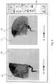
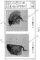
血管構造の少なくとも2つ以上の二次元X線画像を使用するこの実施形態は、血管奇形の三次元表示の特定の計算を可能にする。図7に示されるより具体的な詳細な実施形態の例から明らかになるように、たとえば異なる角度の好ましい実施形態のような異なる画像取得パラメータの2つのX線画像におけるこのような輪郭取りは、受信された上記2つの異なる輪郭に基づいて血管奇形の三次元表示を推定することによって計算することを可能にする。特に、図7に示される患者の脳の2つの異なるDSA画像を使用することができる。 This embodiment, which uses at least two or more two-dimensional radiographic images of the vascular structure, allows for specific calculations of a three-dimensional representation of vascular malformations. Such contouring in two X-ray images with different image acquisition parameters, such as preferred embodiments at different angles, is as evidenced by the more specific example of the embodiment shown in FIG. It makes it possible to calculate by estimating the three-dimensional representation of the vascular malformation based on the two different contours received. In particular, two different DSA images of the patient's brain shown in FIG. 7 can be used.
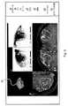
本発明の別の例示的な実施形態に従って、上記二次元X線画像データは、二次元デジタルサブトラクション血管造影画像データであり、上記二次元X線画像データと上記変換二次元画像データとを重ね合わせるステップは、第1および第2のDSA画像を用いて行われる。このような実施形態は、たとえば図7および図8の実施形態に見ることができる。上記第1のDSA画像は、上記第2のDSA画像と比較して異なる取得パラメータ、たとえば別の画像化角度で取得されたものである。さらに、たとえば図7に示される左図および図7に示される右図から推測できるように、上記第1および第2のDSA画像は、上記同一の三次元画像データからの変換二次元画像データと重ね合わせられて、第1および第2のオーバーレイを生じさせる。この実施形態に係る方法はさらに、上記第1および第2の二次元X線画像データをユーザインターフェイス上に表示するステップを備える。これらの画像を表示するためにコンピュータの画面が使用されてもよい。上記ユーザインターフェイスを介して第1および第2の輪郭取り入力を受信するステップが、上記方法のさらなるステップとして含まれる。上記第1の輪郭取り入力は、上記第1の二次元X線画像データにおける上記血管奇形の第1の外形/境界を表す。さらに、上記第2の輪郭取り入力は、上記第2の二次元X線画像データにおける上記血管奇形の第2の外形/境界を表す。上記方法はさらに、上記第1の輪郭取り入力を介して受信された上記第1の外形に基づいて第1の三次元オブジェクトを計算するステップと、第2の輪郭取り入力として受信された上記第2の外形に基づいて第2の三次元オブジェクトを計算するステップを備える。さらに、上記方法は、上記第1および第2の三次元オブジェクトを計算上の方法で交差させることによって、上記血管奇形の上記三次元表示を計算するステップを備える。たとえば図7の実施形態の左側のDSA画像および右側のDSA画像における受信された輪郭に基づいて、図8に示される血管奇形の三次元表示をこの実施形態の方法によって計算することができる。 According to another exemplary embodiment of the present invention, the two-dimensional X-ray image data is two-dimensional digital subtraction angiography image data, and the two-dimensional X-ray image data and the converted two-dimensional image data are superimposed. The steps are performed using the first and second DSA images. Such embodiments can be seen, for example, in the embodiments of FIGS. 7 and 8. The first DSA image is acquired with different acquisition parameters, for example, different imaging angles as compared with the second DSA image. Further, as can be inferred from, for example, the left figure shown in FIG. 7 and the right figure shown in FIG. 7, the first and second DSA images are the same as the converted two-dimensional image data from the same three-dimensional image data. Overlaid to give rise to first and second overlays. The method according to this embodiment further comprises a step of displaying the first and second two-dimensional X-ray image data on the user interface. Computer screens may be used to display these images. The step of receiving the first and second contouring inputs via the user interface is included as a further step of the method. The first contouring input represents the first contour / boundary of the vascular malformation in the first two-dimensional X-ray image data. Further, the second contouring input represents the second contour / boundary of the vascular malformation in the second two-dimensional X-ray image data. The method further comprises a step of calculating a first 3D object based on the first contour received via the first contouring input and the first contouring input received as the second contouring input. It comprises a step of calculating a second 3D object based on the outer shape of 2. Further, the method comprises a step of calculating the three-dimensional representation of the vascular malformation by intersecting the first and second three-dimensional objects in a computational manner. For example, based on the received contours in the left DSA image and the right DSA image of the embodiment of FIG. 7, the three-dimensional representation of the vascular malformation shown in FIG. 8 can be calculated by the method of this embodiment.
本発明の別の例示的な実施形態に従って、上記方法は、上記血管奇形の上記計算された三次元表示の、テクスチャに基づく画像分析を行うステップと、上記テクスチャに基づく画像分析の結果を使用して上記血管奇形の上記計算された三次元表示をさらに正確にするステップとをさらに備える。 According to another exemplary embodiment of the invention, the method uses the steps of performing a texture-based image analysis of the calculated three-dimensional representation of the vascular malformation and the results of the texture-based image analysis. Further include a step to make the calculated three-dimensional representation of the vascular malformation more accurate.
なお、本発明の文脈において、三次元データセットにおける「テクスチャ」という表現は、ボクセルに基づく、すなわち強度に基づく分析として理解される。この分析は、三次元画像データ内の開始点の隣接する画像領域において行われてもよい。当業者によって理解されるように、本発明の文脈において使用される「テクスチャ」は、計算された三次元表示の表面パラメータとは関係がない。したがって、テクスチャに基づく画像分析は、画像コントラストの値の差異または三次元データセット内の濃淡値の差異を識別する。言い換えれば、計算された三次元表示のテクスチャに基づく画像分析は、ボクセル、またはグループ、またはボクセルもしくはボクセルおよびその近傍、すなわち周囲の領域の粒度または粒状性を識別する。 It should be noted that, in the context of the present invention, the expression "texture" in a three-dimensional dataset is understood as a voxel-based, i.e., intensity-based analysis. This analysis may be performed in an image region adjacent to the starting point in the 3D image data. As will be appreciated by those skilled in the art, the "texture" used in the context of the present invention has nothing to do with the calculated surface parameters of the three-dimensional representation. Therefore, texture-based image analysis identifies differences in image contrast values or shade values within a three-dimensional dataset. In other words, image analysis based on the calculated texture of the three-dimensional display identifies the grain size or graininess of the voxels, or groups, or voxels or voxels and their vicinity, i.e., the surrounding area.
代替的に、濃淡値の予め定められた閾値を上回るボクセルおよび下回るボクセルを全て分類するという意味において、濃淡値の閾値化が画像分析として行われてもよい。 Alternatively, shading may be thresholded as an image analysis in the sense that all voxels above and below a predetermined threshold of shading are classified.
本発明の別の局面に従って、コンピュータ上で実行されると、またはコンピュータにロードされると、上記コンピュータに先行する実施形態または局面のいずれか1つに記載の方法の方法ステップを実行させるプログラム、
ならびに/または、上記プログラムが格納されるプログラム記憶媒体、
ならびに/または、少なくとも1つのプロセッサおよびメモリおよび/もしくは上記プログラム記憶媒体を備えるコンピュータであって、上記プログラムは、上記コンピュータ上で実行されるか、もしくは上記コンピュータの上記メモリにロードされる、コンピュータ、
ならびに/または、上記プログラムを表す情報を搬送する信号波またはデジタル信号波、
ならびに/または、上記プログラムを表すデータストリーム、が提示される。A program, according to another aspect of the invention, which, when executed on or loaded into a computer, causes the computer to perform a method step of the method according to any one of the preceding embodiments or aspects.
And / or a program storage medium in which the above program is stored,
And / or a computer with at least one processor and memory and / or the program storage medium, wherein the program is executed on the computer or loaded into the memory of the computer.
And / or a signal wave or digital signal wave that carries information representing the above program,
And / or a data stream representing the above program is presented.
たとえばディスクのような装置に格納されるコンピュータプログラムは、データファイルであり、ファイルは、読み出されて送信されると、たとえば(物理的な、たとえば電気的な、たとえば技術的に生成された)信号の形式のデータストリームになる。この信号は、本明細書に記載されている信号波として実現され得る。たとえば、信号および/または信号波は、コンピュータネットワーク、たとえばLAN、WLAN、WAN、たとえばインターネットを介して送信されるように構成される。したがって、この局面に係る発明は、代替的にまたは追加的に、上記のプログラムを表すデータストリームに関連していてもよい。 A computer program stored in a device such as a disk is a data file, and the file is, for example, (physically, for example, electrical, for example, technically generated) when read and transmitted. It becomes a data stream in the form of a signal. This signal can be realized as the signal wave described herein. For example, signals and / or signal waves are configured to be transmitted over a computer network, such as a LAN, WLAN, WAN, such as the Internet. Accordingly, the invention according to this aspect may, in an alternative or additional manner, relate to a data stream representing the above program.
本発明の別の局面に従って、医用画像分析システムは、上記の局面に記載のコンピュータを備える。 According to another aspect of the invention, the medical image analysis system comprises the computer described in the above aspect.
本発明の別の局面に従って、血管奇形、特に動静脈奇形(AVM)に治療ビームを照射するための放射線療法治療システムが提示され、上記放射線療法治療システムは、
上記の局面に記載の医用画像分析システムと、
治療ビーム源および患者支持ユニットを備える放射線治療装置とを備え、
上記コンピュータは、上記放射線治療装置に動作可能に結合され、上記治療ビーム源の動作または上記患者支持ユニットの位置のうちの少なくとも1つを制御するための制御信号を上記放射線治療装置に発行する。According to another aspect of the present invention, a radiotherapy treatment system for irradiating a vascular malformation, particularly an arteriovenous malformation (AVM), with a therapeutic beam is presented, wherein the radiotherapy treatment system is described.
With the medical image analysis system described in the above aspect,
Equipped with a radiation therapy device equipped with a treatment beam source and a patient support unit,
The computer is operably coupled to the radiotherapy apparatus and issues a control signal to the radiotherapy apparatus to control at least one of the operation of the treatment beam source or the position of the patient support unit.
定義
このセクションでは、本開示で使用される特定の専門用語の定義が提供され、これらの定義も本開示の一部を構成する。Definitions This section provides definitions of the specific terminology used in this disclosure, and these definitions also form part of this disclosure.
コンピュータによって実現される方法
本発明に係る方法は、たとえばコンピュータによって実現される方法である。たとえば、本発明に係る方法の全てのステップまたはステップのうちのほんの一部(すなわち、ステップの総数未満)は、コンピュータ(たとえば、少なくとも1つのコンピュータ)によって実行することができる。コンピュータによって実現される方法の実施形態は、データ処理方法を実行するためのコンピュータの使用である。コンピュータによって実現される方法の実施形態は、コンピュータが方法の1つのステップ、それ以上のステップ、または全てのステップを実行するように動作されるようなコンピュータの動作に関する方法である。Method realized by computer The method according to the present invention is, for example, a method realized by a computer. For example, all steps or only a portion of the steps (ie, less than the total number of steps) of the method according to the invention can be performed by a computer (eg, at least one computer). An embodiment of the method realized by a computer is the use of a computer to perform a data processing method. An embodiment of a method realized by a computer is a method relating to the operation of the computer such that the computer is operated to perform one step, more steps, or all steps of the method.
コンピュータは、たとえば電子的におよび/または光学的にデータを(技術的に)処理するために、たとえば少なくとも1つのプロセッサと、たとえば少なくとも1つのメモリとを備える。プロセッサは、たとえば、半導体(たとえば少なくとも部分的にnおよび/またはpドープされた半導体、たとえばII-半導体材料、III-半導体材料、IV-半導体材料、V-半導体材料、VI-半導体材料のうちの少なくとも1つ、たとえば(ドープされた)シリコンおよび/またはヒ化ガリウム)である物質または組成物でできている。記載されている計算するステップまたは求めるステップは、たとえばコンピュータによって実行される。求めるステップまたは計算するステップは、たとえば、技術的な方法の枠内で(たとえば、プログラムの枠内で)データを求めるステップである。コンピュータは、たとえば、任意の種類のデータ処理装置(たとえば、電子データ処理装置)である。コンピュータは、そのようなものとして一般に思い付く装置(たとえば、デスクトップPC、ノートブック、ネットブックなど)であってもよいが、たとえば携帯電話または組込みプロセッサなどの任意のプログラム可能な装置であってもよい。コンピュータは、たとえば、「サブコンピュータ」のシステム(ネットワーク)を備えてもよく、各サブコンピュータは、それ自体がコンピュータである。「コンピュータ」という表現は、クラウドコンピュータ(たとえば、クラウドサーバ)を含む。「クラウドコンピュータ」という表現は、たとえば少なくとも1つのクラウドコンピュータのシステムと、たとえばサーバファームなどの複数の動作可能に相互接続されたクラウドコンピュータとを備えるクラウドコンピュータシステムを含む。このようなクラウドコンピュータは、好ましくは、ワールドワイドウェブ(WWW)などのワイドエリアネットワークに接続され、全てがワールドワイドウェブに接続されたいわゆるコンピュータのクラウド内に位置している。このようなインフラストラクチャは、特定のサービスを提供するコンピュータの物理的位置および/または構成をエンドユーザが知らなくてもよい、計算、ソフトウェア、データアクセスおよびストレージサービスを表す「クラウドコンピューティング」で使用される。たとえば、この点において、「クラウド」という表現は、インターネット(ワールドワイドウェブ)の隠喩として使用される。たとえば、クラウドは、インフラストラクチャ・アズ・ア・サービス(IaaS)を計算することを提供する。クラウドコンピュータは、本発明の方法を実行するために使用されるオペレーティングシステムおよび/またはデータ処理アプリケーションのための仮想ホストとして機能することができる。クラウドコンピュータは、たとえば、アマゾンウェブサービス(登録商標)によって提供されるエラスティック・コンピュート・クラウド(EC2)である。コンピュータは、たとえば、データを受信もしくは出力するため、および/または、アナログデジタル変換を行うために、インターフェイスを備える。データは、たとえば、物理的特性を表す、および/または、技術的な信号から生成されるデータである。技術的な信号は、たとえば(技術的な)検出装置(たとえば、マーカー装置を検出するための装置など)および/または(技術的な)分析装置(たとえば、(医用)画像化方法を実行するための装置など)によって生成され、技術的な信号は、たとえば電気信号または光信号である。技術的な信号は、たとえば、コンピュータによって受信または出力されるデータを表す。コンピュータは、好ましくは、コンピュータによって出力された情報をたとえばユーザに対して表示することを可能にする表示装置に動作可能に結合される。表示装置の一例は、ナビゲーション用の「ゴーグル」として使用できる仮想現実装置または拡張現実装置(仮想現実眼鏡または拡張現実眼鏡とも称される)である。このような拡張現実眼鏡の具体例は、グーグルグラス(グーグル社の商標)である。拡張現実装置または仮想現実装置は、ユーザ対話によって情報をコンピュータに入力することにも、コンピュータによって出力された情報を表示することにも使用できる。表示装置の別の例は、たとえば液晶ディスプレイを備える標準的なコンピュータモニタであり、このコンピュータモニタは、コンピュータに動作可能に結合されて、画像情報内容を表示装置上に表示するために使用される信号を生成するための表示制御データをコンピュータから受信する。このようなコンピュータモニタの具体的な実施形態は、デジタルライトボックスである。このようなデジタルライトボックスの一例は、ブレインラボ社の製品であるBuzz(登録商標)である。また、モニタは、スマートフォンまたはパーソナルデジタルアシスタントまたはデジタルメディアプレーヤなどの携帯型の(たとえば、手持ち式の)装置のモニタであってもよい。 A computer comprises, for example, at least one processor and, for example, at least one memory for processing data (technically) electronically and / or optically. The processor may be, for example, among semiconductors (eg, at least partially n and / or p-doped semiconductors such as II-semiconductor materials, III-semiconductor materials, IV-semiconductor materials, V-semiconductor materials, VI-semiconductor materials). It is made of at least one substance or composition, eg (doped) silicon and / or gallium arsenide). The calculated or calculated steps described are performed, for example, by a computer. The seeking or calculating step is, for example, the step of seeking data within the framework of a technical method (eg, within the framework of a program). A computer is, for example, any type of data processing device (eg, an electronic data processing device). The computer may be a device commonly conceived as such (eg, desktop PCs, notebooks, netbooks, etc.), but may be any programmable device, such as a mobile phone or embedded processor. .. The computer may include, for example, a system (network) of "sub-computers", where each sub-computer is itself a computer. The expression "computer" includes a cloud computer (eg, a cloud server). The expression "cloud computer" includes a cloud computer system comprising, for example, a system of at least one cloud computer and a plurality of operable cloud computers such as a server farm. Such cloud computers are preferably connected to a wide area network such as the World Wide Web (WWW) and are all located within the so-called computer cloud connected to the World Wide Web. Such infrastructure is used in "cloud computing" to represent computational, software, data access and storage services where the end user does not need to know the physical location and / or configuration of the computer providing a particular service. Will be done. For example, in this regard, the expression "cloud" is used as a metaphor for the Internet (World Wide Web). For example, the cloud provides to compute Infrastructure as a Service (IaaS). The cloud computer can act as a virtual host for the operating system and / or data processing application used to perform the methods of the invention. The cloud computer is, for example, the Elastic Compute Cloud (EC2) provided by Amazon Web Services®. The computer comprises an interface, for example, for receiving or outputting data and / or for performing analog-to-digital conversion. The data are, for example, data that represent physical properties and / or are generated from technical signals. The technical signal is, for example, to perform a (technical) detector (eg, a device for detecting a marker device) and / or a (technical) analyzer (eg, a (medical) imaging method). The technical signal produced by the device, etc.) is, for example, an electrical signal or an optical signal. A technical signal represents, for example, data received or output by a computer. The computer is preferably operably coupled to a display device that allows the information output by the computer to be displayed to, for example, the user. An example of a display device is a virtual reality device or augmented reality device (also referred to as virtual reality glasses or augmented reality glasses) that can be used as "goggles" for navigation. A specific example of such augmented reality glasses is Google Glass (a trademark of Google Inc.). The augmented reality device or virtual reality device can be used to input information to the computer through user interaction and to display the information output by the computer. Another example of a display device is a standard computer monitor, for example equipped with a liquid crystal display, which is operably coupled to a computer and used to display image information content on the display device. Receives display control data from the computer to generate the signal. A specific embodiment of such a computer monitor is a digital lightbox. An example of such a digital light box is Buzz®, a product of Brainlab. The monitor may also be a monitor for a portable (eg, handheld) device such as a smartphone or personal digital assistant or digital media player.
また、本発明は、コンピュータ上で実行されると、本明細書に記載されている方法ステップのうちの1つ以上または全てをコンピュータに実行させるプログラム、および/または、(特に、非一時的な形式で)プログラムが格納されるプログラム記憶媒体、および/または、上記プログラム記憶媒体を備えるコンピュータ、および/または、たとえば本明細書に記載されている方法ステップのうちのいずれかまたは全てを実行するように適合されたコード手段を備えるプログラム(たとえば、上記のプログラム)を表す情報を搬送する、(物理的な、例えば電気的な、たとえば技術的に生成された)信号波、たとえばデジタル信号波に関する。 Also, the invention is a program that, when executed on a computer, causes the computer to perform one or all of the method steps described herein, and / or (especially non-temporary). A program storage medium in which the program is stored (in a form) and / or a computer equipped with the above program storage medium, and / or, for example, to perform any or all of the method steps described herein. With respect to a signal wave (physically, eg, electrically, eg, technically generated), eg, a digital signal wave, that carries information representing a program (eg, the program described above) with code means adapted to.
本発明の枠内で、コンピュータプログラム要素は、ハードウェアおよび/またはソフトウェア(これは、ファームウェア、常駐ソフトウェア、マイクロコードなどを含む)によって具体化することができる。本発明の枠内で、コンピュータプログラム要素は、コンピュータ使用可能な(たとえば、コンピュータ読取可能な)データ記憶媒体によって具体化することができるコンピュータプログラム製品の形式を取ってもよく、このデータ記憶媒体は、命令実行システムでの使用のためにまたは命令実行システムと関連付けて上記データ記憶媒体において具体化されるコンピュータ使用可能な(たとえば、コンピュータ読取可能な)プログラム命令、「コード」または「コンピュータプログラム」を備える。このようなシステムは、コンピュータであってもよく、コンピュータは、本発明に係るコンピュータプログラム要素および/またはプログラムを実行するための手段を備えるデータ処理装置(たとえば、コンピュータプログラム要素を実行するデジタルプロセッサ(中央処理装置またはCPU)と、任意にコンピュータプログラム要素を実行するために使用されるデータおよび/またはコンピュータプログラム要素を実行することによって生成されるデータを格納するための揮発性メモリ(たとえば、ランダムアクセスメモリまたはRAM)とを備えるデータ処理装置)であってもよい。本発明の枠内で、コンピュータ使用可能な(たとえば、コンピュータ読取可能な)データ記憶媒体は、命令実行システム、装置またはデバイスでの使用のためにまたは命令実行システム、装置またはデバイスと関連付けてプログラムを含有、格納、通信、伝搬または伝送することができる任意のデータ記憶媒体であってもよい。コンピュータ使用可能な(たとえば、コンピュータ読取可能な)データ記憶媒体は、たとえば、電子、磁気、光学式、電磁気、赤外線または半導体システム、装置またはデバイス、またはたとえばインターネットなどの伝搬媒体であり得るが、これらに限定されるものではない。さらに、コンピュータ使用可能なまたはコンピュータ読取可能なデータ記憶媒体は、たとえば、プログラムが印刷された紙または他の好適な媒体であってもよい。なぜなら、プログラムは、たとえば紙または他の好適な媒体を光学的にスキャンすることによって電子的に取り込むことができ、次いで、好適な態様で編集、解釈または他の処理を行うことができるからである。データ記憶媒体は、好ましくは、不揮発性データ記憶媒体である。コンピュータプログラム製品ならびに本明細書に記載されているいかなるソフトウェアおよび/またはハードウェアも、例示的な実施形態において本発明の機能を実行するためのさまざまな手段を構成する。コンピュータおよび/またはデータ処理装置は、たとえば、ガイダンス情報を出力するための手段を含むガイダンス情報装置を含み得る。ガイダンス情報は、視覚的表示手段(たとえば、モニタおよび/またはランプ)によって視覚的に、および/または、聴覚的表示手段(たとえば、スピーカおよび/またはデジタル音声出力装置)によって聴覚的に、および/または、触知的表示手段(たとえば、振動要素または機器に組み込まれた振動要素)によって触知的に、たとえばユーザに対して出力されてもよい。本文献の目的のために、コンピュータは、たとえば、技術的な、たとえば有形の構成要素(たとえば、機械的および/または電子的な構成要素)を備える技術的なコンピュータである。本文献においてこのようなものとして記載されているいかなる装置も、技術的な、たとえば有形の装置である。 Within the framework of the present invention, computer program elements can be embodied by hardware and / or software, which includes firmware, resident software, microcode, and the like. Within the framework of the present invention, the computer program element may be in the form of a computer program product that can be embodied by a computer-usable (eg, computer-readable) data storage medium, which is the data storage medium. Computer-enabled (eg, computer-readable) program instructions, "codes" or "computer programs" that are embodied in the above data storage media for use in the instruction execution system or in connection with the instruction execution system. Be prepared. Such a system may be a computer, wherein the computer is a data processing device (eg, a digital processor that executes a computer program element) comprising means for executing a computer program element and / or a program according to the present invention. A central processor (or CPU) and volatile memory (eg, random access) for storing data that is optionally used to execute computer program elements and / or data generated by executing computer program elements. It may be a data processing device) including a memory or a RAM). Within the framework of the present invention, a computer-usable (eg, computer-readable) data storage medium can be programmed for use in an instruction execution system, device or device or in association with an instruction execution system, device or device. It may be any data storage medium that can be contained, stored, communicated, propagated or transmitted. Computer-usable (eg, computer-readable) data storage media can be, for example, electronic, magnetic, optical, electromagnetic, infrared or semiconductor systems, devices or devices, or propagation media such as the Internet. Not limited to. Further, the computer-usable or computer-readable data storage medium may be, for example, paper on which the program is printed or other suitable medium. This is because the program can be electronically captured, for example by optically scanning paper or other suitable medium, and then edited, interpreted or other processed in a suitable manner. .. The data storage medium is preferably a non-volatile data storage medium. Computer program products and any software and / or hardware described herein constitute various means for performing the functions of the invention in exemplary embodiments. Computers and / or data processing devices may include, for example, a guidance information device that includes means for outputting guidance information. Guidance information is visually and / or by visual display means (eg, monitors and / or lamps) and / or by auditory display means (eg, speakers and / or digital audio output devices). , Tactilely may be output tactilely, eg, to the user, by a tactile display means (eg, a vibrating element or a vibrating element built into the device). For the purposes of this document, a computer is, for example, a technical computer with technical, eg, tangible components (eg, mechanical and / or electronic components). Any device described as such in this document is a technical, eg, tangible device.
データを提供する
本開示によれば、データを提供するという表現とデータを検索するという表現とは同義で使用される。「データを提供する」または「データを検索する」という表現は、たとえば、コンピュータによって実現される方法またはプログラムによってデータが求められるシナリオを(コンピュータによって実現される方法の枠内に)包含する。しかし、それは、たとえばユーザ入力を介してデータを受信すること、および/または、データ記憶装置からデータを検索することも含む。Providing Data According to the present disclosure, the terms providing data and searching for data are used interchangeably. The phrase "providing data" or "searching for data" includes, for example, a computer-implemented method or a programmatically sought-after scenario (within the framework of a computer-implemented method). However, it also includes receiving data, for example via user input, and / or retrieving data from a data storage device.
データを求めることは、たとえば物理量を測定して、測定された値をデータ(たとえば、デジタルデータ)に変換すること、および/または、コンピュータによってデータを計算(および、たとえば出力)することを、たとえば本発明に係る方法の枠内に包含する。「データを提供する」ことの意味は、たとえば、たとえばコンピュータによって実現される方法またはプログラムによるさらなる処理のために、たとえば別のプログラム、上記の方法ステップまたはデータ記憶媒体から、コンピュータによって実現される方法またはプログラムによってデータが受信または検索される(たとえば、コンピュータによって実現される方法またはプログラムに入力される)シナリオも包含する。しかし、取得すべきデータの生成は、本発明に係る方法の一部でなくてもよい。したがって、「データを提供する」という表現は、たとえばデータの受信を待つこと、および/または、データを受信することも意味し得る。受信したデータは、たとえばインターフェイスを介して入力され得る。「データを提供する」という表現は、コンピュータによって実現される方法またはプログラムが、データソース、たとえばデータ記憶媒体(たとえば、ROM、RAM、データベース、ハードドライブなど)から、またはインターフェイスを介して(たとえば、別のコンピュータまたはネットワークから)データを(積極的に)受信または検索するためにステップを実行することも意味し得る。開示されている方法または装置によって提供されるデータは、それぞれ、データ記憶媒体に位置するデータベースから取得されてもよく、データ記憶装置は、コンピュータに動作可能にされて、データベースとコンピュータとの間で(たとえば、データベースからコンピュータへの)データ転送を行う。コンピュータは、データを求めるステップのための入力として使用されるデータを取得する。求められたデータは、同一のまたは別のデータベースに再び出力されて、その後の使用に備えて格納され得る。上記のデータベースまたは開示されている方法を実現するために使用されるデータベースは、ネットワークデータ記憶装置もしくはネットワークサーバ(たとえば、クラウドデータ記憶装置もしくはクラウドサーバ)に位置してもよく、またはローカルデータ記憶装置(開示されている方法を実行する少なくとも1つのコンピュータに動作可能に接続された大容量記憶装置など)に位置してもよい。データは、提供するステップの前に追加のステップを実行することによって、「使用できる状態」にすることができる。この追加のステップに従って、データは、取得されることを目的として生成される。たとえば、データは、(たとえば、分析装置によって)検出または取り込まれる。代替的にまたは追加的に、データは、追加のステップに従って、たとえばインターフェイスを介して入力される。たとえば、生成されたデータは、(たとえば、コンピュータに)入力されてもよい。(提供するステップに先立つ)追加のステップに従って、データは、データ記憶媒体(たとえば、ROM、RAM、CDおよび/またはハードドライブなど)にデータを格納する追加のステップを実行することによっても提供可能であり、それによって、本発明に係る方法またはプログラムの枠内でデータは使用できる状態になる。したがって、「データを提供する」ステップは、取得すべきデータを得るおよび/または提供するように装置に命令することも含み得る。特に、提供するステップは、身体との実質的な物理的干渉になるであろう侵襲性のステップを含まない。この侵襲性のステップは、実行するのに医学の専門知識を必要とし、必要な専門的治療および知識をもって実行したとしても実質的な健康上のリスクを伴う。特に、データを提供する(たとえば、データを求める)ステップは、手術ステップを含まず、特に手術または療法を使用して人間または動物の体を治療するステップを含まない。この方法によって使用されるさまざまなデータを区別するために、データは、「XYデータ」などと表記され(すなわち、称され)、それらが表す情報の観点から定義され、それらが表す情報は、好ましくは「XY情報」などと称される。 Obtaining data is, for example, measuring a physical quantity and converting the measured value into data (eg, digital data) and / or calculating (and, for example, outputting) the data by a computer, for example. It is included in the framework of the method according to the present invention. The meaning of "providing data" is, for example, a method realized by a computer or a method realized by a computer, for example, from another program, the method steps described above, or a data storage medium, for further processing by a program. It also includes scenarios in which data is received or retrieved by a program (eg, a method implemented by a computer or entered into a program). However, the generation of data to be acquired does not have to be part of the method according to the invention. Thus, the phrase "providing data" can also mean, for example, waiting for data to be received and / or receiving data. The received data may be input via an interface, for example. The expression "provide data" is a computer-implemented method or program from a data source, such as a data storage medium (eg, ROM, RAM, database, hard drive, etc.) or through an interface (eg, ROM, RAM, database, hard drive, etc.). It can also mean performing steps to (proactively) receive or retrieve data (from another computer or network). The data provided by the disclosed methods or devices may be obtained from a database located in the data storage medium, respectively, and the data storage device is made operational by the computer between the database and the computer. Transfer data (for example, from a database to a computer). The computer gets the data used as input for the step of requesting the data. The requested data may be output again to the same or another database and stored for further use. The above database or the database used to implement the disclosed method may be located in a network data storage device or network server (eg, cloud data storage device or cloud server), or a local data storage device. It may be located (such as a mass storage device operably connected to at least one computer performing the disclosed method). The data can be "ready to use" by performing additional steps before the step to provide. According to this additional step, the data is generated for the purpose of being retrieved. For example, data is detected or captured (eg, by an analyzer). Alternatively or additionally, the data is entered, for example, through an interface, following additional steps. For example, the generated data may be input (eg, to a computer). According to the additional steps (prior to the step of providing), the data can also be provided by performing additional steps of storing the data in a data storage medium (eg, ROM, RAM, CD and / or hard drive, etc.). Yes, thereby making the data available within the framework of the method or program according to the invention. Thus, the "provide data" step may also include instructing the device to obtain and / or provide the data to be acquired. In particular, the steps provided do not include invasive steps that would result in substantial physical interference with the body. This invasive step requires medical expertise to perform and carries with it substantial health risks, even if performed with the necessary professional treatment and knowledge. In particular, the steps that provide data (eg, seek data) do not include surgical steps, especially the steps of treating the human or animal body using surgery or therapy. In order to distinguish the various data used by this method, the data are referred to as "XY data" etc. (ie, referred to) and are defined in terms of the information they represent, the information they represent is preferred. Is called "XY information" or the like.
レジスタリング/コレジスタリング
ナビゲーションシステムに格納された画像(CT、MRなど)の画像データポイントが手術室における空間内の実際の物体(たとえば、身体部分)の各ポイントの空間的位置に割り当てられるときに、身体のn次元画像に対してレジストレーション、すなわちコレジストレーションが行われる。When image data points of an image (CT, MR, etc.) stored in a registering / co-registration navigation system are assigned to the spatial position of each point of an actual object (eg, body part) in space in the operating room. In addition, registration, that is, co-registration, is performed on the n-dimensional image of the body.
画像レジストレーション/画像コレジストレーション
画像レジストレーション、すなわちコレジストレーションは、さまざまなデータセットを1つの座標系に変換するプロセスである。これらのデータは、さまざまなセンサ、さまざまな時間またはさまざまな観点からの複数の写真および/またはデータであってもよい。画像レジストレーションは、コンピュータビジョン医用画像化で使用され、衛星からの画像およびデータの編集および分析で使用される。レジストレーションは、これらのさまざまな測定から得られるデータを比較または統合できるようにするために必要である。Image Registration / Image Registration Image registration, or registration, is the process of transforming different datasets into a single coordinate system. These data may be multiple photographs and / or data from different sensors, different times or different perspectives. Image registration is used in computer vision medical imaging and is used in the editing and analysis of images and data from satellites. Registration is necessary to be able to compare or integrate the data obtained from these various measurements.
なお、本開示では、レジスタリング/コレジスタリングと画像レジストレーションおよび画像コレジストレーションとは同義で使用される。 In this disclosure, registering / co-registration and image registration and image registration are used interchangeably.
アトラス/アトラスセグメント化
好ましくは、解剖学的身体部分の全体三次元形状を表す(たとえば、規定する、より特定的には示すおよび/またはである)アトラスデータが取得される。したがって、アトラスデータは、解剖学的身体部分のアトラスを表す。アトラスは、一般に、複数のオブジェクトの一般モデルで構成され、オブジェクトの一般モデルは、複雑な構造を構成する。たとえば、アトラスは、複数の人体、たとえばこのような人体の画像を含む医用画像から収集された解剖学的情報から生成された患者の身体(たとえば、身体の一部)の統計モデルを構成する。したがって、原則的に、アトラスデータは、複数の人体についてのこのような医用画像データの統計的分析の結果を表す。この結果は、画像として出力可能であるため、アトラスデータは、医用画像データを含む、または医用画像データに相当する。このような比較は、たとえばアトラスデータと医用画像データとの間で画像融合を行う画像融合アルゴリズムを適用することによって行うことができる。比較の結果は、アトラスデータと医用画像データとの間の類似性の程度であり得る。アトラスデータは、たとえばアトラスデータと医用画像データとを比較して、アトラスデータによって規定される解剖学的構造に対応する医用画像データにおける解剖学的構造の位置を判断するために、(たとえば、柔軟なまたは融通の利かない画像融合アルゴリズムを適用することによって)たとえば医用画像データに含まれる画像情報(たとえば、位置画像情報)とマッチングさせることができる画像情報(たとえば、位置画像情報)を備える。Atlas / Atlas segmentation Preferably, atlas data representing (eg, defining, more specifically showing and / or) the entire three-dimensional shape of an anatomical body part is acquired. Therefore, the atlas data represents the atlas of the anatomical body part. An atlas is generally composed of a general model of a plurality of objects, and a general model of an object constitutes a complex structure. For example, the Atlas constitutes a statistical model of a patient's body (eg, a part of the body) generated from anatomical information collected from multiple human bodies, such as medical images containing images of such human bodies. Therefore, in principle, the atlas data represents the result of a statistical analysis of such medical image data for multiple human bodies. Since this result can be output as an image, the atlas data includes medical image data or corresponds to medical image data. Such comparisons can be made, for example, by applying an image fusion algorithm that performs image fusion between atlas data and medical image data. The result of the comparison can be the degree of similarity between the atlas data and the medical image data. The atlas data is, for example, flexible to compare the atlas data with the medical image data to determine the position of the anatomical structure in the medical image data corresponding to the anatomical structure defined by the atlas data (eg, flexible). It comprises image information (eg, position image information) that can be matched, for example, with image information (eg, position image information) contained in medical image data (eg, by applying an inflexible image fusion algorithm).
人体は、その解剖学的構造がアトラスデータを生成するための入力の役割を果たすのだが、有利なことに、性別、年齢、人種、体測値(たとえば、サイズおよび/または質量)および病理学的状態のうちの少なくとも1つなどの共通の特徴を共有している。解剖学的情報は、たとえば人体の解剖学的構造を表し、たとえば人体についての医用画像情報から抽出される。たとえば、大腿骨のアトラスは、構造全体を構成するオブジェクトとして、頭、首、身体、大転子、小転子および下肢を備えていてもよい。たとえば、脳のアトラスは、構造全体を構成するオブジェクトとして、終脳、小脳、間脳、脳橋、中脳および髄質を備えていてもよい。このようなアトラスの一用途は、医用画像のセグメント化におけるものであり、そこでは、アトラスと医用画像データとをマッチングし、マッチングされたアトラスのオブジェクトに画像データポイント(画素またはボクセル)を割り当てるために画像データとマッチングされたアトラスとを比較することによって、画像データをオブジェクトにセグメント化する。 The human body, whose anatomy serves as an input for generating atlas data, has the advantage of gender, age, race, body measurements (eg size and / or mass) and disease. They share common features such as at least one of the physical states. The anatomical information represents, for example, the anatomical structure of the human body and is extracted from, for example, medical image information about the human body. For example, the femoral atlas may include the head, neck, body, greater trochanter, lesser trochanter, and lower limbs as objects that make up the entire structure. For example, a brain atlas may include the telencephalon, cerebellum, diencephalon, pons, midbrain, and medulla as objects that make up the entire structure. One use of such an atlas is in the segmentation of medical images, where the atlas and medical image data are matched and image data points (pixels or voxels) are assigned to the matched atlas objects. By comparing the image data with the matched atlas, the image data is segmented into objects.
治療ビーム
本発明は、治療計画の生成の分野に関し、この治療計画に基づいて治療ビームが制御される。治療ビームは、治療対象の身体部分(以下では、「治療身体部分」と称される)を治療する。これらの身体部分は、たとえば患者の身体の部分、すなわち解剖学的身体部分である。Treatment Beam The present invention relates to the field of treatment plan generation, the treatment beam is controlled based on this treatment plan. The therapeutic beam treats the body part to be treated (hereinafter referred to as "therapeutic body part"). These body parts are, for example, the patient's body parts, i.e., the anatomical body parts.
本発明は、医学の分野、たとえば患者の身体の部分を治療するための放射線ビームなどのビームの使用に関し、そのため、ビームは治療ビームとも称される。治療ビームは、治療対象の身体部分(以下では、「治療身体部分」と称される)を治療する。これらの身体部分は、たとえば患者の身体の部分、すなわち解剖学的身体部分である。治療の目的でたとえば電離放射線が使用される。たとえば、治療ビームは、電離放射線を備えるか、または電離放射線で構成される。電離放射線は、電子を原子または分子から分離してそれらを電離させるのに十分に活発な粒子(たとえば、亜原子粒子もしくはイオン)または電磁波を備えるか、またはそれらの粒子で構成される。このような電離放射線の例としては、X線、高エネルギ粒子(高エネルギ粒子ビーム)および/または放射性元素から放出された電離放射線が挙げられる。治療放射線(たとえば、治療ビーム)は、たとえば腫瘍学の分野などにおける放射線治療または放射線療法で使用される。特に癌を治療するために、腫瘍などの病理学的構造または組織を備える身体の部分は、電離放射線を使用して治療される。そして、腫瘍は、治療身体部分の一例である。 The present invention relates to the medical field, eg, the use of a beam such as a radiation beam to treat a part of the patient's body, hence the beam is also referred to as a therapeutic beam. The therapeutic beam treats the body part to be treated (hereinafter referred to as "therapeutic body part"). These body parts are, for example, the patient's body parts, i.e., the anatomical body parts. For example, ionizing radiation is used for therapeutic purposes. For example, the therapeutic beam comprises or is composed of ionizing radiation. Ionized radiation comprises or is composed of particles (eg, subatomic particles or ions) or electromagnetic waves that are active enough to separate electrons from atoms or molecules and ionize them. Examples of such ionizing radiation include X-rays, high energy particles (high energy particle beams) and / or ionizing radiation emitted from radioactive elements. Therapeutic radiation (eg, therapeutic beams) is used in radiation therapy or radiotherapy, for example in the field of oncology. Parts of the body with pathological structures or tissues, such as tumors, are treated with ionizing radiation, especially to treat cancer. And the tumor is an example of a treated body part.
治療ビームは、好ましくは、治療身体部分を貫通するように制御される。しかし、治療ビームは、治療身体部分の外側の身体部分に対しては悪影響を及ぼす可能性がある。これらの身体部分は、ここでは「外側身体部分」と称される。一般に、治療ビームは、治療身体部分に到達して治療身体部分を貫通するために、外側身体部分を貫通しなければならない。 The treatment beam is preferably controlled to penetrate the treatment body part. However, the therapeutic beam can adversely affect body parts outside the treated body part. These body parts are referred to herein as "outer body parts". In general, the therapeutic beam must penetrate the outer body part in order to reach and penetrate the treated body part.
この点において、以下のウェブページも参照されたい:
http://www.elekta.com/healthcare_us_elekta_vmat.phpおよびhttp://www.varian.com/us/oncology/treatments/treatment_techniques/rapidarc。See also the following web page in this regard:
http://www.elekta.com/healthcare_us_elekta_vmat.php and http://www.varian.com/us/oncology/treatments/treatment_techniques/rapidarc.
さらに、本発明の一局面を参照しながら上記および下記される特徴、機能、要素および/またはステップは、上記および下記される本発明のその他の局面にも等しく適用される、ということが強調される。特に、第1の局面に係る方法を参照しながら上記および下記される特徴および/またはステップは、第2の局面に係るコンピュータプログラム、第3の局面に係るコンピュータ読取可能媒体、第4の局面に係るコンピュータおよび/または第5の局面に係る医療システムにも等しく適用され、逆もまた同様である。 Further, it is emphasized that, with reference to one aspect of the invention, the features, functions, elements and / or steps described above and below apply equally to the other aspects of the invention described above and below. To. In particular, the features and / or steps described above and below with reference to the method according to the first aspect are described in the computer program according to the second aspect, the computer readable medium according to the third aspect, and the fourth aspect. Equally applies to such computers and / or medical systems according to the fifth aspect, and vice versa.
本発明のこれらのおよび他の局面は、下記の実施形態から明らかであり、下記の実施形態を参照しながら説明される。 These and other aspects of the invention are evident from the embodiments below and will be described with reference to the embodiments below.
以下では、本発明の背景説明を提供しかつ本発明の例示的な実施形態を示す添付の図面を参照しながら、本発明について説明する。しかし、本発明の範囲は、図面の文脈に開示されている具体的特徴に限定されるものではない。 Hereinafter, the present invention will be described with reference to the accompanying drawings which provide a background description of the present invention and show exemplary embodiments of the present invention. However, the scope of the invention is not limited to the specific features disclosed in the context of the drawings.
図面は、概略的であるに過ぎず、縮尺に合致しているわけではない。原則的に、図中、同一または同様の部分、要素および/またはステップは、同一または同様の参照記号で記載される。 The drawings are only schematic and do not fit the scale. In principle, the same or similar parts, elements and / or steps in the figure are described with the same or similar reference symbols.
実施形態の説明
図1は、本発明の例示的な実施形態に係る二次元/三次元画像コレジストレーションの、コンピュータによって実現される医用方法のステップを示すフローチャートを概略的に示す。図1は、血管奇形の三次元表示を計算する新たな方法を提供することによって、血管奇形を含む血管構造の二次元X線画像データの利点と、同一の血管構造の三次元画像データの利点とを組み合わせる。特に、二次元X線画像データの利点は、解像度が高いことであり、特に血管構造内の造影剤の分布の進展に関して、動脈と静脈との間の差異が医師またはこのような画像を分析するコンピュータアルゴリズムが見てはっきり分かるほどであるという事実である。したがって、この方法は、二次元X線画像データの上記の利点と、三次元データセットの利点、すなわち血管奇形(たとえば、AVM)を空間的な三次元の態様でユーザに対して有利に表示して示すことができるという利点とを組み合わせる。これは、血管奇形のいかなる治療も計画する際に医師にとって大きな助けになる。Description of the Embodiment FIG. 1 schematically shows a flowchart showing steps of a computer-implemented medical method of 2D / 3D image registration according to an exemplary embodiment of the invention. FIG. 1 shows the advantages of 2D X-ray image data of vascular structures including vascular malformations and the advantages of 3D image data of identical vascular structures by providing a new way to calculate the 3D representation of vascular malformations. Combine with. In particular, the advantage of two-dimensional X-ray image data is the high resolution, especially with respect to the evolution of the distribution of contrast agent in the vascular structure, the difference between arteries and veins analyzes the doctor or such images. The fact that computer algorithms are clearly visible. Therefore, this method presents the above advantages of 2D X-ray image data and the advantages of 3D datasets, i.e., vascular malformations (eg, AVM) in a spatial 3D aspect to the user. Combined with the advantage of being able to show. This is of great help to physicians in planning any treatment for vascular malformations.
図1の方法は、造影剤を含む血管構造の二次元X線画像データを提供するステップ(ステップS1)を備え、上記血管構造は、血管奇形を含む。さらに、上記血管構造の三次元画像データを提供するステップ(ステップS2)および上記三次元画像データを変換二次元画像データに変換するステップ(ステップS3)も含まれる。さらに、上記二次元X線画像データと上記変換二次元画像データとが重ね合わせられて、上記二次元X線画像データと上記変換二次元画像データとの間の対応関係が計算されることによって、上記二次元X線画像データと上記三次元画像データとの間のコレジストレーションを決定/実現する(すなわち、ステップS4)。さらに、上記コレジストレーションがなされた二次元X線画像データにおいて上記血管奇形を判断するステップ(ステップS5)と、上記コレジストレーションがなされた二次元X線画像データの上記判断された血管奇形に基づいて、上記血管奇形の三次元表示を計算するステップ(ステップS6)とが上記方法によって含まれる。 The method of FIG. 1 comprises a step (step S1) of providing two-dimensional X-ray image data of a vascular structure containing a contrast agent, the vascular structure comprising a vascular malformation. Further, a step of providing the three-dimensional image data of the blood vessel structure (step S2) and a step of converting the three-dimensional image data into the converted two-dimensional image data (step S3) are also included. Further, the two-dimensional X-ray image data and the converted two-dimensional image data are superimposed, and the correspondence between the two-dimensional X-ray image data and the converted two-dimensional image data is calculated. The registration between the two-dimensional X-ray image data and the three-dimensional image data is determined / realized (that is, step S4). Further, the step of determining the vascular malformation in the two-dimensional X-ray image data subjected to the registration (step S5) and the determined vascular malformation in the two-dimensional X-ray image data subjected to the co-registration are performed. Based on the above method, the step (step S6) of calculating the three-dimensional display of the vascular malformation is included.
図1に記載されている方法によって、二次元および三次元画像のコレジストレーションは、フレームレスの態様で行われる。コレジストレーションがなされた二次元X線画像データおよび三次元画像データにより、血管奇形の表示を三次元座標系において計算することができる。この方法は、血管奇形がたとえば人間の脳におけるAVMである場合に特に有効である。人間の脳に関して言えば手術および/または放射線手術および/または放射線療法は非常にリスクが高いので、本発明の利点、すなわち血管奇形の三次元表示の精密な計算は、この医療の文脈では非常に有効である。しかし、図1の方法は、AVMに限定されるものではなく、脳の領域に限定されるものではない。 By the method described in FIG. 1, registration of 2D and 3D images is performed in a frameless manner. The display of vascular malformations can be calculated in a 3D coordinate system using the co-registrated 2D X-ray image data and 3D image data. This method is particularly effective when the vascular malformation is, for example, AVM in the human brain. Since surgery and / or radiation surgery and / or radiation therapy are very risky when it comes to the human brain, the advantage of the present invention, namely the precise calculation of the three-dimensional representation of vascular malformations, is very high in this medical context. It is valid. However, the method of FIG. 1 is not limited to AVM and is not limited to brain regions.
さらに、図1の方法によって、二次元および三次元画像のレジストレーション/コレジストレーションは、フレームレスの態様で行われる。したがって、二次元X線画像データと三次元画像データとの間のコレジストレーションを決定するステップは、フレームレス画像レジストレーションとして実行可能であり、および/または、実行される。したがって、本発明では、頭蓋骨の外側にあるローカライザとは対照的に、フレームを取り付ける必要がなく、追加フレームを取得する必要がなく、痛みが生じることがなく、臨床上の負荷、コストおよび時間の削減が実現され、脳内の画像情報に基づいたより正確なレジストレーションが提供される。 Further, by the method of FIG. 1, registration / registration of 2D and 3D images is performed in a frameless manner. Therefore, the step of determining the registration between the 2D X-ray image data and the 3D image data can and / or is performed as a frameless image registration. Thus, in the present invention, in contrast to the localizer on the outside of the skull, there is no need to attach a frame, obtain an additional frame, cause no pain, and clinical load, cost and time. Reductions are achieved and more accurate registrations are provided based on image information in the brain.
図1の方法は、高解像度の二次元X線画像の恩恵を受け、その中の1つの血管を明確に区別できるいうメリットの恩恵を受けるため、奇形の輪郭を選択するための血管構造についての高度な詳細を提供する。この解像度が高いというメリットおよび血管奇形の動脈流入と静脈流出とを光学的に区別できるというメリットは、次いで、血管奇形の三次元表示を計算することによって三次元データセットに転写される。コレジストレーションがなされた二次元X線画像データおよび三次元画像データにより、血管奇形の表示を三次元座標系において計算することができる。 The method of FIG. 1 benefits from a high-resolution two-dimensional X-ray image and benefits from the ability to clearly distinguish one vessel within it, thus relating to the vascular structure for selecting malformed contours. Provides advanced details. This high resolution advantage and the ability to optically distinguish between arterial inflow and venous outflow of vascular malformations is then transferred to a three-dimensional dataset by computing a three-dimensional representation of the vascular malformation. The display of vascular malformations can be calculated in a 3D coordinate system using the co-registrated 2D X-ray image data and 3D image data.
図2は、暗い色で示される造影剤を含む人間の脳の血管構造23および血管奇形24の2つの異なる二次元DSA画像20,21を概略的に示す。両方のDSA画像は、異なる角度から画像化されており、左側の画像20は、正面から取り込まれたDSAであり、右側の画像21は、側面から取り込まれたDSAである。このように、たとえば図1の実施形態におけるステップS1について記載されているように二次元X線画像データが提供される。 FIG. 2 schematically shows two different two-
図3にも2つの異なるDSA画像30,31が示されており、これらの各々は、同一の人間の脳の三次元飛行時間(TOF)MR画像の最大値投影像(MIP)32,33と重ね合わせられる。したがって、図3で使用されるソフトウェアは、三次元画像データの投影像、特にMIPを計算することによって、三次元画像データ、すなわち三次元飛行時間(TOF)MR画像を変換二次元画像データに既に変換している。MIP32,33は、ユーザに対してカラー表示されてもよく、色の強度は、基本となる三次元データセットにおける対応するボクセルの濃淡値に対応または相互に関係があってもよい。 Two
図3に示されるオーバーレイは、MIPが生成された投影パラメータの自動最適化を開始することによってさらに向上され得る。ノブ36を押すと、ソフトウェアは、MIPパラメータを自動的に最適化し、それによって、複数のMIPパラメータセットについて二次元X線画像30とそれぞれの変換二次元画像32との間の画像対応関係の程度を最適化する。ノブ36が押された場合に、同様のことが画像31および33にも当てはまる。このように、反復最適化プロセスを先に詳細に説明したように使用することができる。なお、変換二次元画像と提供された二次元X線画像との間の画像対応関係の程度を最適化するために、たとえば画素単位または領域単位に二次元画像データを比較するたとえば画像比較を行うことができる。このようにして、2つの二次元画像データ間の対応関係の値が計算されてもよく、他のMIPパラメータのために計算された他の値と比較されてもよく、その結果、最適な結果を生じさせる。ノブ34および35によって、血管構造における造影剤の分布の時系列を示す複数の画像である二次元X線画像データ30,31は再生可能である。したがって、これにより、奇形への動脈流入と奇形からの静脈流出との区別に関して、複数の画像から最適な画像を識別することが可能になる。 The overlay shown in FIG. 3 can be further enhanced by initiating automatic optimization of the projected parameters generated by the MIP. When the
図4は、セグメント化による注目領域(ROI)の適用を概略的に示す。図4は、それぞれのMIP投影像42,43と重ね合わせられた、正面および側面から取り込まれたDSA画像40,41を示す。ユーザは、さらなる手順のために、血管構造の提供された三次元画像データの一部を選択することができる。それによって、選択は、ROIボタン44を介して提供され得るユーザ入力と組み合わせた自動アトラスセグメント化によって行われる。図4から推測できるように、右頚動脈のみが表示されているが、その理由は、これが、基本となる三次元データセットからセグメント化されたものとしてROIボタン44を介して以前に選択されたからである。 FIG. 4 schematically shows the application of a region of interest (ROI) by segmentation. FIG. 4 shows
図5は、本発明の例示的な実施形態に従って、たとえば図4に示される二次元X線画像データと変換二次元画像データとのオーバーレイ50,51がグラフィカルユーザインターフェイス(GUI)52,53を介してユーザによって調節可能である本発明の実施形態を概略的に示す。上記のように、これにより、最適化のための変換パラメータの初期値についてのユーザ入力を受信することが可能になる。すなわち、変換パラメータの最適化は、このGUI52,53によって開始することができ、それによって、複数の変換パラメータセットについて二次元X線画像データとそれぞれの変換二次元画像データとの間の画像対応関係の程度の最適化をもたらす、またはさらなる最適化を必要とすることなくコレジストレーションを実現する。 FIG. 5 shows, for example, overlays 50, 51 of 2D X-ray image data and converted 2D image data shown in FIG. 4 via a graphical user interface (GUI) 52, 53, according to an exemplary embodiment of the invention. The embodiments of the present invention that are adjustable by the user are schematically shown. As mentioned above, this makes it possible to receive user input about the initial values of the conversion parameters for optimization. That is, the optimization of the conversion parameters can be started by the
図6は、2つのDSA画像60,61を概略的に示す。左側には、正面から取り込まれた二次元X線画像における血管奇形の判断/輪郭取り62に関する本発明の実施形態が示されている。右側には、投影光線63が側面から取り込まれた画像に示されており、この光線は、正面から取り込まれたDSA画像においてユーザ入力を介して受信された輪郭62に基づく。血管奇形の三次元表示は、二次元X線画像データにおける血管奇形の輪郭に基づいて計算される。 FIG. 6 schematically shows two
図7は、本発明の例示的な実施形態に従って、たとえば異なる画像化角度から取られた2つの異なるDSA画像についてグラフィカルユーザインターフェイスを介して輪郭取り70,71入力を受信することができることを概略的に示す。特に、図7に示される本発明の実施形態は、以下のように行うことができる。まず、第1および第2の二次元DSA画像がユーザインターフェイス上に表示され、第1および第2の輪郭取り入力、すなわち外形70,71がユーザインターフェイスを介して受信される。図7から推測できるように、第1の輪郭取り入力は、第1の二次元X線画像データにおける血管奇形の第1の外形70を表し、第2の輪郭取り入力は、第2の二次元X線画像データにおける血管奇形の第2の外形71を表す。さらに、この実施形態では、第1の外形に基づいて第1の三次元オブジェクト(図示せず)が計算され、第2の外形に基づいて第2の三次元オブジェクト(図示せず)が計算される。さらに、第1および第2の三次元オブジェクトは、計算上の方法で交差されることによって、血管奇形の三次元表示を計算する。 FIG. 7 schematically illustrates the ability to receive
図8は、本発明の例示的な実施形態に係る、たとえば図7に示されるコレジストレーションがなされた二次元X線画像データの判断された血管奇形に基づいて計算される血管奇形の結果として生じる三次元表示80を概略的に示す。図7および図8の実施形態について説明される方法は、有利なことに、患者の頭蓋骨内で正確であり、血管セグメント化結果に依存せず、人間の脳の領域における血管奇形(たとえば、AVM)の側に注目することを可能にする、解剖学的構造に基づくフレームレス二次元/三次元画像レジストレーションを容易にする。上記のように、解像度が高いというメリットおよび二次元X線画像において血管奇形の動脈流入と静脈流出とを光学的に区別できるというメリットは、次いで、血管奇形の三次元表示を計算することによって三次元データセットに転写される。コレジストレーションがなされた二次元X線画像データおよび三次元画像データにより、血管奇形の表示を三次元座標系において計算することができる。したがって、二次元X線画像データに示される基本となる血管構造を非常に精密に考慮に入れる血管奇形の三次元オブジェクトを生成することができる。 FIG. 8 is the result of a vascular malformation calculated based on the determined vascular malformation of the co-registrated 2D X-ray image data according to an exemplary embodiment of the invention, eg, FIG. The resulting three-
図9は、血管奇形、特に動静脈奇形(AVM)に治療ビームを照射するための放射線療法治療システム90を概略的に示す。システム90は、医用画像分析システム91と、放射線治療装置95とを備える。放射線治療装置95は、治療ビーム源96と、患者支持ユニット97とを備える。医用画像分析システム91は、プログラム93が格納されるプログラム記憶媒体94を有するコンピュータ92を備える。さらに、プログラム93は、コンピュータ92上で実行されるか、またはコンピュータにロードされると、コンピュータ92に、本発明の第1の局面に係る方法の方法ステップ、たとえば図1の文脈において上記した方法ステップを実行させる。コンピュータは、放射線治療装置95に動作可能に結合され、治療ビーム源96の動作または患者支持ユニット97の位置のうちの少なくとも1つを制御するための制御信号を放射線治療装置に発行する。 FIG. 9 schematically shows a
Claims (21)
Translated fromJapaneseコンピューターのプロセッサが、造影剤を含む血管構造の二次元のDSA画像のシーケンスを提供するステップ(ステップS1)を備え、前記血管構造は、血管奇形を含み、前記方法はさらに、
前記造影剤が動脈流入チャネルを介して血管奇形に既に移動し、かつ静脈流出チャネルを介して前記血管奇形から未だ移動していない分布段階にある画像化された血管構造および造影剤を示す二次元のDSA画像のシーケンスのうちから、少なくとも一つの画像を選択するステップ(ステップS1a)を備え、
前記プロセッサが、前記血管構造の三次元画像データを提供するステップ(ステップS2)と、
前記プロセッサが、前記三次元画像データを変換二次元画像データに変換するステップ(ステップS3)と、
前記プロセッサが、前記二次元のDSA画像と前記変換二次元画像データとを重ね合わせて、前記二次元のDSA画像と前記変換二次元画像データとの間の対応関係を計算することによって、前記二次元のDSA画像と前記三次元画像データとの間のコレジストレーションを決定するステップ(ステップS4)と、
前記プロセッサが、前記コレジストレーションがなされた二次元のDSA画像において前記血管奇形を判断するステップ(ステップS5)と、
前記プロセッサが、前記コレジストレーションがなされた二次元のDSA画像の前記判断された血管奇形に基づいて、前記血管奇形の三次元表示を計算するステップ(ステップS6)とを備える、方法。Aninformation processing method realized by a computerfor 2D / 3D image registration.
A computer processor comprises a step (step S1) of providing asequence of two-dimensionalDSA images of a vascular structure comprising a contrast agent, wherein the vascular structure comprises a vascular malformation, and the method further comprises.
Two-dimensional showing the imaged vascular structure and contrast agent at the distribution stage where the contrast agent has already migrated to the vascular malformation via the arterial inflow channel and has not yet migrated from the vascular malformation via the venous outflow channel. The step (step S1a) of selecting at least one image from the sequence of DSA images of the above is provided.
A step (step S2) in which theprocessor provides three-dimensional image data of the blood vessel structure,
The step (step S3) in which theprocessor converts the three-dimensional image data into the converted two-dimensional image data, and
Theprocessor superimposes the two-dimensionalDSAimageandthe converted two-dimensional image data, and calculates the correspondence between the two-dimensional DSA image and the converted two-dimensional image data. A step (step S4) of determining the registration between the two-dimensionalDSAimage and the three-dimensional image data, and
A step (step S5) in which theprocessor determines the vascular malformation in the collated two-dimensionalDSAimage .
A methodcomprising the step (step S6) of calculating the three-dimensional representation of the vascular malformation based on the determined vascular malformation of the co-registrated two-dimensionalDSAimage .
前記二次元の画像と前記変換二次元画像データとを重ね合わせるステップ(ステップS4)は、
前記変換パラメータを自動的に最適化することによって、複数の変換パラメータセットについて前記二次元のDSA画像と前記それぞれの変換二次元画像データとの間の画像対応関係の程度を最適化するステップを備える、請求項1~3のいずれか1項に記載の方法。The transformation parameter set is used for the transformation of the 3D image data into the transformation 2D image data.
The step (step S4) of superimposing the two-dimensional imageand the converted two-dimensional image data is
A step of optimizing the degree of image correspondence between the 2DDSAimage and each of the converted 2D image data for a plurality of conversion parameter sets by automatically optimizing the conversion parameters. The method according to any oneof claims1 to 3 , which is provided.
2つ以上の翻訳パラメータ、
3つの回転パラメータ、
スケーリングパラメータ、および
焦点距離
のうちの1つ以上である、請求項7に記載の方法。The image acquisition parameters of the two-dimensionalDSAimage are
Two or more translation parameters,
3 rotation parameters,
The method of claim 7, wherein the scaling parameter is one or more of the focal lengths.
前記方法は、
前記プロセッサが、前記三次元画像データおよび/または前記変換二次元画像データから前記人間の脳の少なくとも1つの部分をセグメント化するさらなるステップを備え、
前記人間の脳の前記少なくとも1つのセグメント化された部分のみが前記二次元のDSA画像と重ね合わせられる、請求項1~8のいずれか1項に記載の方法。The vascular structure is that of the human brain
The method is
Theprocessor comprises an additional step of segmenting at least one portion of the human brain from the 3D image data and / or the transformed 2D image data.
The method of any one ofclaims1-8 , wherein only the at least one segmented portion of the human brain is superposed onthe two-dimensional DSAimage .
前記二次元のDSA画像は、前記血管構造および分布状態における前記造影剤の分布を画像化することにより、前記AVMへの動脈流入と前記AVMからの静脈流出との区別を可能にする、請求項1~9のいずれか1項に記載の方法。The malformation is an arteriovenous malformation (AVM).
The two-dimensional DSAimage enables the distinction between arterial influx into theAVM and venous outflow from the AVM by imaging the distribution of the contrast agent in the vascular structure and distribution state. The method according to any one of Items1 to 9 .
前記プロセッサが、前記AVMへの前記動脈流入と前記AVMからの前記静脈流出との前記区別に関して最適な画像を前記複数の画像から識別するステップを備える、請求項10に記載の方法。The two-dimensional DSAimage is a plurality of images showing the time series of the distribution of the contrast medium in the vascular structure, and the method further comprises.
10. The method of claim 10,wherein the processor comprises identifying from the plurality of images the optimal image for the distinction between the arterial influx into the AVM and the venous outflow from the AVM.
前記選択は、自動的に、ユーザ入力なしの自動セグメント化によって、またはユーザ入力と組み合わせた自動アトラスセグメント化によって、または純粋に受信されたユーザ入力に基づいて、行われる、請求項1~12のいずれか1項に記載の方法。Theprocessor further comprises a step of selecting a portion of the provided three-dimensional image data of the vascular structure for further use in the method.
The selection is made automatically, either by automatic segmentation withoutuser input, by automatic atlas segmentation in combination with user input, or based on purely received user input. The method according to any one of12 to 12 .
前記二次元のDSA画像において前記血管奇形を輪郭取りするステップを備え、
前記血管奇形の前記三次元表示は、前記二次元のDSA画像における前記血管奇形の輪郭に基づいて計算される、請求項1~13のいずれか1項に記載の方法。The step (step S5) of determining the vascular malformation in the two-dimensionalDSAimage subjected to the registration is
A step of contouring the vascular malformation inthe two-dimensional DSAimage .
The method according to any one ofclaims1 to 13 , wherein the three-dimensional display of the vascular malformation is calculated based on the contour of the vascular malformation inthe two-dimensional DSAimage .
前記第1の二次元X線画像は、前記第2の二次元X線画像と比較して異なる取得パラメータ、または、別の角度で取得されたものであり、
前記方法は、前記第1および前記第2の二次元X線画像について行われる、請求項1~15のいずれか1項に記載の方法。The provided two-dimensionalDSAimage is at least a first and second two-dimensional X-ray image of the vascular structure.
The first two-dimensional X-ray image is acquired with different acquisition parametersor different angles as compared with the second two-dimensional X-ray image.
The method according to any oneof claims1 to 15 , wherein the method is performed on the first and second two-dimensional X-ray images.
前記第1および第2のDSA画像は、前記同一の三次元画像データからの変換二次元画像データと重ね合わせられて、第1および第2のオーバーレイを生じさせ、前記方法はさらに、
前記第1および第2の二次元のDSA画像をユーザインターフェイス上に表示するステップと、
前記ユーザインターフェイスを介して第1および第2の輪郭取り入力を受信するステップとを備え、
前記第1の輪郭取り入力は、前記第1の二次元のDSA画像における前記血管奇形の第1の外形を表し、
前記第2の輪郭取り入力は、前記第2の二次元のDSA画像における前記血管奇形の第2の外形を表し、前記方法はさらに、
前記プロセッサが、前記第1の外形に基づいて第1の三次元オブジェクトを計算するステップと、
前記プロセッサが、前記第2の外形に基づいて第2の三次元オブジェクトを計算するステップと、
前記プロセッサが、前記第1および第2の三次元オブジェクトを計算上の方法で交差させることによって、前記血管奇形の前記三次元表示を計算するステップとを備える、請求項1~13のいずれか1項に記載の方法。The first DSA image is acquired with different acquisition parametersor different angles as compared with the second DSA image.
The first and second DSA images are superimposed on the converted two-dimensional image data from the same three-dimensional image data to give rise to first and second overlays, the method further comprising.
The step of displaying the first and second two-dimensionalDSAimages on the user interface, and
It comprises a step of receiving first and second contouring inputs via the user interface.
The first contouring input represents the first contour of the vascular malformation in the first two-dimensionalDSAimage .
The second contouring input represents a second contour of the vascular malformation in the second two-dimensionalDSAimage , and the method further comprises.
A step in which theprocessor calculates a first 3D object based on the first contour.
A step in which theprocessor calculates a second 3D object based on the second contour.
1 The method described in the section.
前記プロセッサが、前記テクスチャに基づく画像分析の結果を使用して前記血管奇形の前記計算された三次元表示をさらに正確にするステップとをさらに備える、請求項1~17のいずれか1項に記載の方法。A step in whichthe processor performs a texture-based image analysis of the calculated three-dimensional representation of the vascular malformation.
13._ The method described.
請求項20に記載の医用画像分析システム(91)と、
治療ビーム源(96)および患者支持ユニット(97)を備える放射線治療装置(95)とを備え、
前記コンピュータは、前記放射線治療装置に動作可能に結合され、前記治療ビーム源の動作または前記患者支持ユニットの位置のうちの少なくとも1つを制御するための制御信号を前記放射線治療装置に発行する、放射線療法治療システム(90)。A radiotherapy treatment system (90) for irradiating a vascular malformation, especially an arteriovenous malformation (AVM), with a therapeutic beam.
The medical image analysis system (91) according to claim 20 and
A radiation therapy device (95) with a treatment beam source (96) and a patient support unit (97).
The computer is operably coupled to the radiotherapy device and issues a control signal to the radiotherapy device to control at least one of the operation of the treatment beam source or the position of the patient support unit. Radiation therapy treatment system (90).
Applications Claiming Priority (1)
| Application Number | Priority Date | Filing Date | Title |
|---|---|---|---|
| PCT/EP2019/059450WO2020207597A1 (en) | 2019-04-12 | 2019-04-12 | Frameless anatomy-based 2d/3d image registration |
Publications (2)
| Publication Number | Publication Date |
|---|---|
| JP2021520236A JP2021520236A (en) | 2021-08-19 |
| JP7055872B2true JP7055872B2 (en) | 2022-04-18 |
Family
ID=66182580
Family Applications (1)
| Application Number | Title | Priority Date | Filing Date |
|---|---|---|---|
| JP2020529486AActiveJP7055872B2 (en) | 2019-04-12 | 2019-04-12 | Computer-enhanced information processing methods, programs, medical image analysis systems, and radiation therapy treatment systems for 2D / 3D image registration. |
Country Status (4)
| Country | Link |
|---|---|
| US (1) | US11410317B2 (en) |
| EP (1) | EP3746980B1 (en) |
| JP (1) | JP7055872B2 (en) |
| WO (1) | WO2020207597A1 (en) |
Families Citing this family (7)
| Publication number | Priority date | Publication date | Assignee | Title |
|---|---|---|---|---|
| KR101996476B1 (en)* | 2018-12-27 | 2019-07-03 | (주)제이엘케이인스펙션 | Apparatus for providing brain disease and method for the same |
| WO2020163539A1 (en)* | 2019-02-05 | 2020-08-13 | University Of Virginia Patent Foundation | System and method for fully automatic lv segmentation of myocardial first-pass perfusion images |
| USD1021915S1 (en)* | 2020-09-22 | 2024-04-09 | Brainlab Ag | Display screen or portion thereof with a transitional graphical user interface |
| USD1013702S1 (en)* | 2020-09-22 | 2024-02-06 | Brainlab Ag | Display screen or portion thereof with graphical user interface |
| CN115082534B (en)* | 2022-07-21 | 2022-12-16 | 杭州三坛医疗科技有限公司 | Biplane image registration method and device and robot |
| CN115375649B (en)* | 2022-08-19 | 2025-07-25 | 复旦大学 | Arteriovenous malformation grading method and device based on time-enhanced image histology |
| DE102023200770A1 (en)* | 2023-01-31 | 2024-08-01 | Siemens Healthineers Ag | Providing a results dataset |
Citations (2)
| Publication number | Priority date | Publication date | Assignee | Title |
|---|---|---|---|---|
| US20090005668A1 (en) | 2007-06-30 | 2009-01-01 | West Jay B | Non-invasive method for using 2D angiographic images for radiosurgical target definition |
| JP2011254861A (en) | 2010-06-04 | 2011-12-22 | Toshiba Corp | Medical image processor |
Family Cites Families (8)
| Publication number | Priority date | Publication date | Assignee | Title |
|---|---|---|---|---|
| US5827187A (en)* | 1996-04-23 | 1998-10-27 | Mayo Foundation For Medical Education And Research | Dynamic MR digital subtraction angiography with complex subtraction |
| EP1563799B2 (en) | 2004-02-11 | 2012-11-28 | BrainLAB AG | Adjustable marker arrangement |
| US7097357B2 (en)* | 2004-06-02 | 2006-08-29 | General Electric Company | Method and system for improved correction of registration error in a fluoroscopic image |
| US20060036167A1 (en)* | 2004-07-03 | 2006-02-16 | Shina Systems Ltd. | Vascular image processing |
| US7835500B2 (en)* | 2005-11-16 | 2010-11-16 | Accuray Incorporated | Multi-phase registration of 2-D X-ray images to 3-D volume studies |
| WO2011119960A1 (en) | 2010-03-25 | 2011-09-29 | Beth Israel Deaconess Medical Center | System and method for frameless stereotactic radiosurgery of arteriovenous malformations |
| EP3005943B1 (en)* | 2013-06-03 | 2020-09-23 | Samsung Life Public Welfare Foundation | Novel magnetic resonance image technique for imaging and evaluating collateral circulation |
| CN103810754A (en) | 2014-03-04 | 2014-05-21 | 姜卫剑 | Medical image processing method |
- 2019
- 2019-04-12JPJP2020529486Apatent/JP7055872B2/enactiveActive
- 2019-04-12USUS16/762,372patent/US11410317B2/enactiveActive
- 2019-04-12WOPCT/EP2019/059450patent/WO2020207597A1/ennot_activeCeased
- 2019-04-12EPEP19717876.7Apatent/EP3746980B1/enactiveActive
Patent Citations (2)
| Publication number | Priority date | Publication date | Assignee | Title |
|---|---|---|---|---|
| US20090005668A1 (en) | 2007-06-30 | 2009-01-01 | West Jay B | Non-invasive method for using 2D angiographic images for radiosurgical target definition |
| JP2011254861A (en) | 2010-06-04 | 2011-12-22 | Toshiba Corp | Medical image processor |
Non-Patent Citations (1)
| Title |
|---|
| Femke Steenbeke, et al.,Analysis of the targeting uncertainty of a stereotactic frameless radiosurgery technique for arteriovenous malformation,Radiotherapy and Oncology,ELSEVIER,2014年12月,Vol. 113, Issure 3,第371-373頁 |
Also Published As
| Publication number | Publication date |
|---|---|
| JP2021520236A (en) | 2021-08-19 |
| US11410317B2 (en) | 2022-08-09 |
| US20210233252A1 (en) | 2021-07-29 |
| EP3746980A1 (en) | 2020-12-09 |
| EP3746980B1 (en) | 2022-08-03 |
| WO2020207597A1 (en) | 2020-10-15 |
Similar Documents
| Publication | Publication Date | Title |
|---|---|---|
| JP7055872B2 (en) | Computer-enhanced information processing methods, programs, medical image analysis systems, and radiation therapy treatment systems for 2D / 3D image registration. | |
| JP7120584B2 (en) | SUBJECT POSITIONING DEVICE, SUBJECT POSITIONING METHOD, SUBJECT POSITIONING PROGRAM, AND RADIATION THERAPY SYSTEM | |
| US11443441B2 (en) | Deep inspiration breath-hold setup using x-ray imaging | |
| US10543381B2 (en) | System for monitoring the position of a patient receiving 4pi radiation therapy | |
| US9492124B2 (en) | System and method for treatment planning of organ disease at the functional and anatomical levels | |
| US20150055848A1 (en) | Mechanism for advanced structure generation and editing | |
| JP6397846B2 (en) | Mechanisms for advanced structure generation and editing | |
| US11669982B2 (en) | Soft tissue stereo-tracking | |
| US10926106B2 (en) | Patient pre-positioning in frameless cranial radiosurgery using thermal imaging | |
| US11565129B2 (en) | Binary tracking of an anatomical tracking structure on medical images | |
| EP3218057B1 (en) | Target region partitioning in radiation therapy for minimising irradiation of non-target tissue | |
| JP7537432B2 (en) | Image-Based Device Tracking | |
| US9401051B2 (en) | Mechanism for dynamically propagating real-time alterations of medical images | |
| NL2016800B1 (en) | Method of positioning an interventional device. | |
| US20250242177A1 (en) | Ct-less free breathing image contour for planning radiation treatment | |
| EP4522267B1 (en) | Determining physically correct digitally reconstructed radiographs | |
| Fernandes et al. | RFUDS--A Brain Metastases Imaging Dataset of Radiotherapy Follow-Up | |
| WO2025026523A1 (en) | Self-validating elastic fusion |
Legal Events
| Date | Code | Title | Description |
|---|---|---|---|
| A621 | Written request for application examination | Free format text:JAPANESE INTERMEDIATE CODE: A621 Effective date:20200529 | |
| A131 | Notification of reasons for refusal | Free format text:JAPANESE INTERMEDIATE CODE: A131 Effective date:20210720 | |
| A521 | Request for written amendment filed | Free format text:JAPANESE INTERMEDIATE CODE: A523 Effective date:20211019 | |
| TRDD | Decision of grant or rejection written | ||
| A01 | Written decision to grant a patent or to grant a registration (utility model) | Free format text:JAPANESE INTERMEDIATE CODE: A01 Effective date:20220308 | |
| A61 | First payment of annual fees (during grant procedure) | Free format text:JAPANESE INTERMEDIATE CODE: A61 Effective date:20220406 | |
| R150 | Certificate of patent or registration of utility model | Ref document number:7055872 Country of ref document:JP Free format text:JAPANESE INTERMEDIATE CODE: R150 | |
| R250 | Receipt of annual fees | Free format text:JAPANESE INTERMEDIATE CODE: R250 | |
| S533 | Written request for registration of change of name | Free format text:JAPANESE INTERMEDIATE CODE: R313533 | |
| R350 | Written notification of registration of transfer | Free format text:JAPANESE INTERMEDIATE CODE: R350 |