JP7055671B2 - Cuff for blood pressure monitor - Google Patents
Cuff for blood pressure monitorDownload PDFInfo
- Publication number
- JP7055671B2 JP7055671B2JP2018047057AJP2018047057AJP7055671B2JP 7055671 B2JP7055671 B2JP 7055671B2JP 2018047057 AJP2018047057 AJP 2018047057AJP 2018047057 AJP2018047057 AJP 2018047057AJP 7055671 B2JP7055671 B2JP 7055671B2
- Authority
- JP
- Japan
- Prior art keywords
- wrist
- cuff
- core
- sphygmomanometer
- worn
- Prior art date
- Legal status (The legal status is an assumption and is not a legal conclusion. Google has not performed a legal analysis and makes no representation as to the accuracy of the status listed.)
- Active
Links
- 230000036772blood pressureEffects0.000titledescription12
- 238000005259measurementMethods0.000claimsdescription6
- 238000005452bendingMethods0.000claimsdescription4
- 210000000707wristAnatomy0.000description91
- 238000010586diagramMethods0.000description8
- 230000002093peripheral effectEffects0.000description7
- 238000013459approachMethods0.000description4
- 210000001367arteryAnatomy0.000description2
- 238000003780insertionMethods0.000description2
- 230000037431insertionEffects0.000description2
- 239000004744fabricSubstances0.000description1
- 230000010349pulsationEffects0.000description1
- 239000011347resinSubstances0.000description1
- 229920005989resinPolymers0.000description1
- 230000000630rising effectEffects0.000description1
- 210000003813thumbAnatomy0.000description1
Images


Landscapes
- Measuring Pulse, Heart Rate, Blood Pressure Or Blood Flow (AREA)
Description
Translated fromJapanese本発明は、被測定部位に巻かれる帯状の血圧計用カフに関する。 The present invention relates to a band-shaped sphygmomanometer cuff wrapped around a measurement site.
従来、血圧計用カフは、略円筒状の一部が切欠かれて開口部を有する弾性体のコアを備え、開口部から挿入した上腕または手首に装着できるようにすると共に、装着した際に、容易に外れないように、上腕または手首をある程度覆うように構成される(例えば、特許文献1参照)。 Conventionally, a sphygmomanometer cuff has an elastic core having a substantially cylindrical portion cut out and has an opening so that it can be attached to an upper arm or wrist inserted through the opening, and when attached, it is attached. It is configured to cover the upper arm or wrist to some extent so that it does not easily come off (see, for example, Patent Document 1).
特許文献1には、カフ帯に人体の上腕に略沿うことができる湾曲板(コア)を収容し、湾曲板の両端間に人体の上腕を挿入することができる開口を形成する血圧計用カフが開示されている。また、特許文献1には、湾曲板の一端部が、外側にはね上げ変形した血圧計用カフが開示されている。 In Patent Document 1, a sphygmomanometer cuff that accommodates a curved plate (core) that can substantially follow the upper arm of the human body in a cuff band and forms an opening in which the upper arm of the human body can be inserted between both ends of the curved plate. Is disclosed. Further, Patent Document 1 discloses a sphygmomanometer cuff in which one end of a curved plate is flipped outward and deformed.
しかしながら、特許文献1に記載の血圧計用カフは、湾曲板の一端部が、他端部側に傾斜するように、はね上げ変形しているため、上腕を開口から湾曲板内に挿入する際に、このはね上げ変形した形状の先端に上腕が当たってしまい、装着性が悪い、という問題がある。 However, the sphygmomanometer cuff described in Patent Document 1 is deformed by flipping up so that one end of the curved plate is inclined toward the other end, and therefore, when the upper arm is inserted into the curved plate from the opening. There is a problem that the upper arm hits the tip of this flip-up deformed shape and the wearability is poor.
そこで、本発明は、容易に外れないようにすると共に、装着性を向上させた血圧計用カフを提供することを目的としている。 Therefore, an object of the present invention is to provide a sphygmomanometer cuff that is not easily removed and has improved wearability.
前記目的を達成するために、本発明の血圧計用カフは、被測定部位に巻くように装着されるカバー体に収容され、前記被測定部位に沿うように湾曲する弾性体のコアを備え、前記コアは、略円筒状の一部が切欠かれてなる開口を有する断面C字状のコア本体と、前記コア本体の端部から、前記コア本体の外側であって、前記コア本体の端部間を結ぶ平面の垂直面に対して遠ざかる方向に延在する返し部と、を備えることを特徴とする。 In order to achieve the above object, the sphygmomanometer cuff of the present invention is housed in a cover body wound around the measured portion, and includes an elastic core that curves along the measured portion. The core has a core body having a C-shaped cross section having an opening formed by cutting out a part of a substantially cylindrical shape, and an end portion of the core body which is outside the core body from the end portion of the core body. It is characterized by including a barb extending in a direction away from the vertical plane of the plane connecting the spaces.
このように構成された本発明の血圧計用カフは、容易に外れないようにすると共に、装着性を向上させることができる。 The sphygmomanometer cuff of the present invention configured in this way can be prevented from being easily removed and can be easily worn.
以下、本発明による血圧計用カフを実現する実施形態を、図面に示す実施例1から実施例3に基づいて説明する。 Hereinafter, embodiments for realizing the sphygmomanometer cuff according to the present invention will be described with reference to Examples 1 to 3 shown in the drawings.
まず、実施例1における血圧計用カフの構成を説明する。
実施例1における血圧計用カフは、被測定部位としての手首の血圧を測る手首装着型血圧計に備わる手首装着型血圧計用カフに適用される。First, the configuration of the sphygmomanometer cuff in Example 1 will be described.
The sphygmomanometer cuff in Example 1 is applied to a wrist-worn sphygmomanometer cuff provided in a wrist-worn sphygmomanometer that measures the blood pressure of the wrist as a measurement site.
[手首装着型血圧計の構成]
図1は、実施例1の手首装着型血圧計用カフを備えた手首装着型血圧計の構成を示す斜視図である。図2は、実施例1の手首装着型血圧計用カフを備えた手首装着型血圧計の構成を示す断面図である。以下、図1および図2に基づいて、実施例1の手首装着型血圧計の構成を説明する。[Structure of wrist-worn sphygmomanometer]
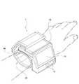
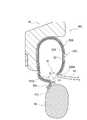
FIG. 1 is a perspective view showing the configuration of a wrist-worn sphygmomanometer provided with a wrist-worn sphygmomanometer cuff according to the first embodiment. FIG. 2 is a cross-sectional view showing the configuration of a wrist-worn sphygmomanometer provided with a wrist-worn sphygmomanometer cuff according to the first embodiment. Hereinafter, the configuration of the wrist-worn sphygmomanometer of Example 1 will be described with reference to FIGS. 1 and 2.
手首装着型血圧計1は、図1に示すように、装置本体10と、手首Mに巻き付けられる手首装着型血圧計用カフ20と、を備える。装置本体10の表面には、表示部11と、操作部12と、を備える。 As shown in FIG. 1, the wrist-mounted sphygmomanometer 1 includes a device
装置本体10は、手首装着型血圧計1が手首Mに装着された状態で、手の甲側から親指側にわたって配置され、被測定者が、表示部11を視認し、操作部12を操作可能なようになっている。装置本体10の内部には、図示しないポンプ、スローリーク弁、圧力センサー等を内蔵する。 The device
手首装着型血圧計用カフ20は、図2に示すように、手首Mに巻くように装着されるカバー体21と、カバー体21の内部に収容される空気袋22およびコア30と、を備える。 As shown in FIG. 2, the wrist-
カバー体21は、帯状の布等で形成され、手首Mの一般的な周長よりも長く形成される。カバー体21の折り返し部21aの近傍には、面ファスナ23が取り付けられる。面ファスナ23は、装置本体10の上面に設けられた面ファスナ24に押し付けることで固定される。 The
空気袋22は、樹脂シートにより形成された袋状の部材から形成される。空気袋22は、装置本体10のポンプから導入された空気により膨張する。 The
このように構成された手首装着型血圧計1では、手首装着型血圧計用カフ20を手首Mに巻き、面ファスナ23と面ファスナ24とを貼り付けることで、手首装着型血圧計1を被測定者の手首Mに装着する。手首装着型血圧計1を被測定者の手首Mに装着した状態で、操作部12を操作することで、装置本体10のポンプから、空気袋22の内部に、空気が導入される。空気袋22に空気が導入されると、手首Mの動脈が圧迫される。 In the wrist-mounted sphygmomanometer 1 configured in this way, the wrist-mounted sphygmomanometer 1 is covered by wrapping the wrist-mounted
その後、装置本体10に内蔵されているポンプの駆動が止められ、空気袋22内の空気を、装置本体10に内蔵されたスローリーク弁より徐々に抜くことにより、空気袋22内の圧力を下げる。このとき、手首Mの動脈の脈動による空気袋22内の圧力の変化を、装置本体10に内蔵された圧力センサーにて検出し、表示部11に表示するようになっている。 After that, the drive of the pump built in the device
[コアの構成]
図3は、実施例1の手首装着型血圧計用カフのコアの構成を示す側面図である。以下、図3に基づいて、実施例1の手首装着型血圧計のコアの構成を説明する。[Core configuration]
FIG. 3 is a side view showing the configuration of the core of the wrist-worn sphygmomanometer cuff according to the first embodiment. Hereinafter, the configuration of the core of the wrist-worn sphygmomanometer of Example 1 will be described with reference to FIG.
コア30は、可とう性を有する弾性体で形成され、図3に示すように、手首Mに沿うように湾曲するコア本体31と、コア本体31から張り出した返し部36aと、から構成される。 The
コア本体31は、断面略円弧状の底部32と、底部32の両端から起立する側壁部33a,33bと、側壁部33a,33bの先端から内側に屈曲して形成される窄み部34a,34bと、から構成される。 The core
窄み部34a,34bの端部35a,35bは、開放端として形成される。端部35aと、端部35bとの間には、開口長hの開口50が形成される。開口50は、図3の上下方向において、コア本体31の略中央に形成される。図3の左右方向において、端部35aと、端部35bとは、略同じ位置にある。 The
すなわち、コア本体31は、略円筒状の一部が切欠かれてなる開口50を有する断面C字状に形成される。なお、開口長hは、断面C形状を形成する端部35aと端部35bとの最短距離とする。 That is, the core
返し部36aは、コア本体31の端部35aから、コア本体31の外側であって、コア本体31の端部35a,35b間を結ぶ平面P1の垂直面P2に対して遠ざかる方向に延在する。言い換えると、返し部36aは、断面C字状を形成する端部35a,35bのうち、装置本体10が取り付けられる側(図3で上側)の端部35aから、コア本体31の外周面の外側で、開口50が広がる方向に張り出して形成される。返し部36aの側面37aは、平坦に形成される。 The
なお、返し部36aの側面37aは、曲面形状であってもよい。また、返し部36aは、断面C字状を形成する端部35a,35bのうち、装置本体10が取り付けられる側(図3で上側)の端部35aとは反対側の端部35bから、コア本体31の外周面の外側で、開口50が広がる方向に張り出して形成されてもよい。 The
次に、実施例1の手首装着型血圧計用カフ20の作用を説明する。
図4Aは、実施例1の手首装着型血圧計用カフの作用を説明する説明図であり、手首が返し部の側面に当接した状態を示す。図4Bは、実施例1の手首装着型血圧計用カフの作用を説明する説明図であり、開口が広げられた状態を示す。Next, the operation of the wrist-worn
FIG. 4A is an explanatory diagram illustrating the operation of the wrist-worn sphygmomanometer cuff of Example 1, and shows a state in which the wrist is in contact with the side surface of the return portion. FIG. 4B is an explanatory diagram illustrating the operation of the wrist-worn sphygmomanometer cuff of Example 1, and shows a state in which the opening is widened.
実施例1の手首装着型血圧計用カフ20は、被測定部位(手首M)に巻くように装着されるカバー体21に収容され、被測定部位(手首M)に沿うように湾曲する弾性体のコア30を備える。コア30は、略円筒状の一部が切欠かれてなる開口を有する断面C字状のコア本体31と、コア本体31の端部35aから、コア本体31の外側であって、コア本体31の端部間を結ぶ平面P1の垂直面P2に対して遠ざかる方向に延在する返し部36aと、を備える(図3)。 The wrist-worn
手首装着型血圧計用カフ20を手首Mに装着する際は、図4Aに示すように、被測定者が、装置本体10を手で持ち、手首装着型血圧計用カフ20の開口51を、被測定者の手首Mに向けて移動させる。ここで、手首装着型血圧計用カフ20の開口51は、コア本体31の開口50に対し、カバー体21の厚みを考慮したものであり、開口50と相関関係にある。 When the wrist-mounted
手首装着型血圧計用カフ20が、手首Mに近づくと、手首Mが、カバー体21を介して、返し部36aの側面37aに当たる。手首Mが、カバー体21を介して、返し部36aの側面37aに当たった状態で、手首装着型血圧計1を手首Mに近づく方向に移動させると、側面37aが手首Mに押される。 When the wrist-worn
側面37aが手首Mに押されると、図4Bに示すように、コア本体31の形状が変形し、開口51が開口長Hより長い開口長Haとなり、開口51が広がる。開口51が広がった状態で、手首装着型血圧計1を手首Mに近づく方向にさらに移動させると、手首Mが、開口51を通過し、手首装着型血圧計用カフ20が手首Mに装着される。 When the
すなわち、手首装着型血圧計1を手首Mに装着する際に、手首Mを返し部36aの側面37aに押し付けて、コア本体31の開口50が開く方向に、コア30を変形させることができる。そのため、手首装着型血圧計用カフ20の手首Mへの装着性を向上させることができる。 That is, when the wrist-mounted blood pressure monitor 1 is attached to the wrist M, the wrist M can be pressed against the
仮に、窄み部34a,34bを設けずに開口50を大きくしてしまうと、コア本体31が手首Mを保持する保持力が低下し、手首装着型血圧計用カフ20と手首Mとの間に隙間が生じてしまう問題がある。一方、窄み部34a,34bを設けると、開口50が狭くなり、手首Mを手首装着型血圧計用カフ20の内側に挿入する際に、窄み部34a,34bが手首Mに当たってしまう、という問題がある。これに対し、実施例1の手首装着型血圧計1は、窄み部34a,34bを設け、さらに返し部36aを設ける構成により、手首Mを返し部36aの側面37aに押し当てて、開口51を広げることができる。そのため、手首Mを手首装着型血圧計用カフ20の内側に挿入し易くすることができる。 If the
まず、実施例2における手首装着型血圧計用カフの構成を説明する。
図5Aは、実施例2の手首装着型血圧計用カフの構成と作用を説明する説明図であり、手首が返し部の側面に当接した状態を示す。図5Bは、実施例2の手首装着型血圧計用カフの作用を説明する説明図であり、開口が広げられた状態を示す。なお、実施例1で説明した内容と同一乃至均等な部分の説明については、同一用語又は同一の符号を用いて説明する。First, the configuration of the wrist-worn sphygmomanometer cuff in Example 2 will be described.
FIG. 5A is an explanatory diagram illustrating the configuration and operation of the wrist-worn sphygmomanometer cuff according to the second embodiment, and shows a state in which the wrist is in contact with the side surface of the return portion. FIG. 5B is an explanatory diagram illustrating the operation of the wrist-worn sphygmomanometer cuff of Example 2, and shows a state in which the opening is widened. The same or equivalent parts as those described in Example 1 will be described using the same terms or the same reference numerals.
実施例2の手首装着型血圧計用カフ120は、コアの返し部の構成が異なる点で実施例1の手首装着型血圧計用カフ20と相違する。 The wrist-worn
[コアの返し部の構成]
実施例2もコア130は、図5Aに示すように、返し部36aの先端から、コア本体131に近づく方向に屈曲して形成される第2返し部138aを備える。返し部36aの側面37aと、第2返し部138aの側面139aとは、滑らかな曲面で接続される。[Structure of core return part]
Also in the second embodiment, as shown in FIG. 5A, the
次に、実施例2の手首装着型血圧計用カフ120の作用を説明する。
実施例2の手首装着型血圧計用カフ120は、コア30は、返し部36aの先端から、コア本体31に近づく方向に屈曲して形成される第2返し部138aを備える(図5A)。Next, the operation of the wrist-worn
The wrist-worn
手首装着型血圧計用カフ120を手首Mに装着する際は、図5Aに示すように、被測定者が、装置本体10を手で持ち、手首装着型血圧計用カフ120の開口51を、被測定者の手首Mに向けて移動させる。手首装着型血圧計用カフ120が、手首Mに近づくと、手首Mが、カバー体21を介して、返し部36aの側面37aに当たる。 When the wrist-mounted
この際、返し部36aの先端には、第2返し部138aが形成されているため、返し部36aの先端が手首Mに当たることを防止する。 At this time, since the
手首Mが、カバー体21を介して、返し部36aの側面37aに当たった状態で、手首装着型血圧計101を手首Mに近づく方向に移動させると、側面37aが手首Mに押される。側面37aが手首Mに押されると、図5Bに示すように、コア本体31の形状が変形し、開口51が開口長Hより長い開口長Haとなり、開口51が広がる。 When the wrist-mounted
開口51が広がった状態で、手首装着型血圧計101を手首Mに近づく方向にさらに移動させると、手首Mが、開口51を通過し、手首装着型血圧計用カフ120が手首Mに装着される。 When the wrist-mounted
すなわち、手首装着型血圧計用カフ120を手首Mに装着させる際に、手首Mを返し部36aの側面37aに確実に当てることができる。そのため、手首装着型血圧計用カフ120の手首Mへの装着性をさらに向上させることができる。なお、実施例1で説明した内容と同一乃至均等な部分の説明については、同一用語又は同一の符号を用いて説明する。 That is, when the wrist-mounted blood
まず、実施例3における手首装着型血圧計用カフの構成を説明する。
図6Aは、実施例3の手首装着型血圧計用カフの構成と作用を説明する説明図であり、手首が返し部の側面に当接した状態を示す。図6Bは、実施例3の手首装着型血圧計用カフの作用を説明する説明図であり、開口が広げられた状態を示す。なお、実施例1で説明した内容と同一乃至均等な部分の説明については、同一用語又は同一の符号を用いて説明する。First, the configuration of the wrist-worn sphygmomanometer cuff in Example 3 will be described.
FIG. 6A is an explanatory diagram illustrating the configuration and operation of the wrist-worn sphygmomanometer cuff according to the third embodiment, showing a state in which the wrist is in contact with the side surface of the return portion. FIG. 6B is an explanatory diagram illustrating the operation of the wrist-worn sphygmomanometer cuff according to the third embodiment, and shows a state in which the opening is widened. The same or equivalent parts as those described in Example 1 will be described using the same terms or the same reference numerals.
実施例3の手首装着型血圧計用カフ220は、コアの返し部の構成が異なる点で実施例1の手首装着型血圧計用カフ20と相違する。 The wrist-worn
[コアの返し部の構成]
図6Aに示すように、コア本体231の底部32から、コア本体231の装置本体10が取り付けられる側の端部235aまでの距離は、コア本体231の底部32から、コア本体231の装置本体10が取り付けられる側とは反対側の端部235bまでの距離より長く形成される。すなわち、コア本体231の装置本体10が取り付けられる側の端部235aは、コア本体231の装置本体10が取り付けられる側とは反対側の端部235bより突出して設けられる。[Structure of core return part]
As shown in FIG. 6A, the distance from the bottom 32 of the
コア本体231の端部235aから、コア本体231の外側であって、コア本体231の端部235a,235b間を結ぶ平面P1の垂直面P2に対して遠ざかる方向に延在する。言い換えると、コア本体231の端部235aから、コア本体231の外周面の外側で、開口50が広がる方向に張り出して返し部36aが形成される。 It extends from the
なお、コア本体231の装置本体10が取り付けられる側とは反対側の端部235bが、コア本体231の装置本体10が取り付けられる側の端部235aより突出して設けられてもよい。この場合、コア本体231の端部235bから、コア本体231の外周面の外側で、開口50が広がる方向に張り出して返し部が形成される。 It should be noted that the
次に、実施例3の手首装着型血圧計用カフ220の作用を説明する。
実施例3の手首装着型血圧計用カフ220は、コア本体31の一方の端部235aは、コア本体の他方の端部235bより突出して設けられ、返し部36aは、少なくとも突出して設けられたコア本体31の一方の端部235aに設けられる(図6A)。Next, the operation of the wrist-worn
In the wrist-worn
手首装着型血圧計用カフ220を手首Mに装着する際は、図6Aに示すように、被測定者が、装置本体10を手で持ち、手首装着型血圧計用カフ220の開口51を、被測定者の手首Mに向けて移動させる。手首装着型血圧計用カフ220が、手首Mに近づくと、手首Mが、カバー体21を介して、返し部36aの側面37aに当たる。 When the wrist-mounted
この際、返し部36aは、手首Mの手首装着型血圧計用カフ220への挿入軌跡で、コア本体231の端部236bより、手前側にある。そのため、返し部36aの側面37aを、手首Mの手首装着型血圧計用カフ220への挿入軌跡で、手首Mに最初に当てることができる。 At this time, the
手首Mが、カバー体21を介して、返し部36aの側面37aに当たった状態で、手首装着型血圧計201を手首Mに近づく方向に移動させると、側面37aが手首Mに押される。側面37aが手首Mに押されると、図6Bに示すように、コア本体231の形状が変形し、開口51が開口長Hより長い開口長Haとなり、開口51が広がる。 When the wrist-mounted
開口51が広がった状態で、手首装着型血圧計201を手首Mに近づく方向にさらに移動させると、手首Mが、開口50を通過し、手首装着型血圧計用カフ220が手首Mに装着される。 When the wrist-mounted
すなわち、手首装着型血圧計用カフ220を手首Mに装着する軌跡において、手首Mを、一方の端部235aに設けられた返し部36aの側面37aに最初に当てることができる。そのため、手首装着型血圧計用カフ220の手首Mへの装着性をさらに向上させることができる。なお、実施例1で説明した内容と同一乃至均等な部分の説明については、同一用語又は同一の符号を用いて説明する。 That is, in the locus of attaching the wrist-mounted blood
まず、実施例4における手首装着型血圧計用カフの構成を説明する。
図7Aは、実施例4の手首装着型血圧計用カフの構成と作用を説明する説明図であり、手首が返し部の側面に当接した状態を示す。図7Bは、実施例4の手首装着型血圧計用カフの作用を説明する説明図であり、開口が広げられた状態を示す。なお、実施例1で説明した内容と同一乃至均等な部分の説明については、同一用語又は同一の符号を用いて説明する。First, the configuration of the wrist-worn sphygmomanometer cuff in Example 4 will be described.
FIG. 7A is an explanatory diagram illustrating the configuration and operation of the wrist-worn sphygmomanometer cuff according to the fourth embodiment, showing a state in which the wrist is in contact with the side surface of the return portion. FIG. 7B is an explanatory diagram illustrating the operation of the wrist-worn sphygmomanometer cuff of Example 4, and shows a state in which the opening is widened. The same or equivalent parts as those described in Example 1 will be described using the same terms or the same reference numerals.
実施例4の手首装着型血圧計用カフ320は、コアの返し部の構成が異なる点で実施例1の手首装着型血圧計用カフ20と相違する。 The wrist-worn
[コアの返し部の構成]
実施例4のコア330の返し部36a,236aは、図7Aに示すように、コア本体31の端部35a,35bの両方から、コア本体31の外周面の外側で、コア本体31の端部35a,35b間を結ぶ平面P1の垂直面P2に対して遠ざかる方向に延在する。言い換えると、返し部36a,236aは、断面C字状を形成する端部35a,35bの両方から、コア本体31の外周面の外側で、開口50が広がる方向に張り出して形成される。[Structure of core return part]
As shown in FIG. 7A, the
次に、実施例4の手首装着型血圧計用カフ320の作用を説明する。
手首装着型血圧計用カフ320を手首Mに装着する際は、図7Aに示すように、被測定者が、装置本体10を手で持ち、手首装着型血圧計用カフ320の開口51を、被測定者の被測定部位である手首Mに向けて移動させる。Next, the operation of the wrist-worn
When the wrist-mounted
手首装着型血圧計用カフ320が、手首Mに近づくと、手首Mが、カバー体21を介して、返し部36aの側面37aと、返し部336bの側面337bとの少なくとも一方に当たる。手首Mが、カバー体21を介して、返し部36aの側面37aと、返し部336bの側面337bとの少なくとも一方に当たった状態で、手首装着型血圧計1を手首Mに近づく方向に移動させると、手首Mが当たっている側面37a,337bが手首Mに押される。 When the wrist-worn
側面37a,337bが手首Mに押されると、図7Bに示すように、コア本体231の形状が変形し、開口51が開口長Hより長い開口長Haとなり、開口51が広がる。開口51が広がった状態で、手首装着型血圧計301を手首Mに近づく方向にさらに移動させると、手首Mが、開口50を通過し、手首装着型血圧計用カフ220が手首Mに装着される。 When the side surfaces 37a and 337b are pushed by the wrist M, as shown in FIG. 7B, the shape of the core
すなわち、手首装着型血圧計用カフ320を手首Mに装着する際に、手首Mを、少なくとも一方の返し部36a,236aの側面37a,237aに押し付けて、コアの開口が開く方向に、コアを変形させることができる。そのため、手首装着型血圧計用カフ320の手首Mへの装着性をさらに向上させることができる。なお、実施例1で説明した内容と同一乃至均等な部分の説明については、同一用語又は同一の符号を用いて説明する。 That is, when the wrist-mounted blood
以上、本発明の血圧計用カフを実施例1から実施例4に基づき説明してきた。しかし、具体的な構成については、これらの実施例に限られるものではなく、特許請求の範囲の各請求項に係る発明の要旨を逸脱しない限り、各実施例を組み合わせ、設計の変更や追加等は許容される。 The cuff for a sphygmomanometer of the present invention has been described above based on Examples 1 to 4. However, the specific configuration is not limited to these examples, and as long as the gist of the invention according to each claim is not deviated from the claims, the examples are combined, and the design is changed or added. Is acceptable.
実施例2では、返し部36aの先端に第2返し部138aを備える例を示した。しかし、第2返し部としては、実施例3の返し部36aに適用することもできるし、実施例4の返し部336a,336bに適用することもできる。 In Example 2, an example in which the
実施例2では、断面C字状を形成する端部35a,35bの両方に、返し部36a,236aを設ける例を示した。しかし、実施例3のように、コア本体の一方の端部が、コア本体の他方の端部より突出して設けられる場合であっても、コア本体の両方の端部に返し部を設けることができる。 In the second embodiment, an example is shown in which the
実施例1では、本発明を手首装着型血圧計用カフに適用する例を示した。しかし、本発明は、上腕など略円柱状の生体部位を計測する血圧計用カフに適用することができる。 In Example 1, an example of applying the present invention to a wrist-worn sphygmomanometer cuff was shown. However, the present invention can be applied to a sphygmomanometer cuff that measures a substantially columnar biological part such as the upper arm.
1 手首装着型血圧計(血圧計の一例)
20 手首装着型血圧計用カフ(血圧計用カフの一例)
21 カバー体
30 コア
31 コア本体
36a 返し部
50 開口
139a 第2返し部
M 被測定部位としての手首
P1 平面
P2 垂直面1 Wrist-worn sphygmomanometer (an example of sphygmomanometer)
20 Wrist-worn sphygmomanometer cuff (an example of sphygmomanometer cuff)
21
Claims (4)
Translated fromJapanese前記コアは、
略円筒状の一部が切欠かれてなる開口を有する断面C字状のコア本体と、
前記コア本体の前記断面C字状の端部から、前記コア本体の外側であって、前記コア本体の端部間を結ぶ平面の垂直面に対して遠ざかる方向に延在する返し部と、を備える
ことを特徴とする血圧計用カフ。It is housed in a cover body that is wound around the measurement site and has an elastic core that curves along the measurement site.
The core is
A core body with a C-shaped cross section having an opening formed by cutting out a part of a substantially cylindrical shape,
A return portion extending from theC-shaped end portion of the core body in a direction away from the vertical plane of the plane connecting the ends of the core body, which is outside the core body. A cuff for a sphygmomanometer characterized by being prepared.
ことを特徴とする、請求項1に記載の血圧計用カフ。The cuff for a sphygmomanometer according to claim 1, wherein the core includes a second return portion formed by bending from the tip of the return portion in a direction approaching the core body.
前記返し部は、少なくとも突出して設けられた前記コア本体の一方の端部に設けられる
ことを特徴とする、請求項1または2に記載の血圧計用カフ。One end of the core body is provided so as to project from the other end of the core body.
The cuff for a sphygmomanometer according to claim 1 or 2, wherein the return portion is provided at least at one end of the core body provided so as to project.
ことを特徴とする、請求項1から3の何れか一項に記載の血圧計用カフ。The cuff for a sphygmomanometer according to any one of claims 1 to 3, wherein the return portion is provided at both ends of the core body.
Priority Applications (1)
| Application Number | Priority Date | Filing Date | Title |
|---|---|---|---|
| JP2018047057AJP7055671B2 (en) | 2018-03-14 | 2018-03-14 | Cuff for blood pressure monitor |
Applications Claiming Priority (1)
| Application Number | Priority Date | Filing Date | Title |
|---|---|---|---|
| JP2018047057AJP7055671B2 (en) | 2018-03-14 | 2018-03-14 | Cuff for blood pressure monitor |
Publications (2)
| Publication Number | Publication Date |
|---|---|
| JP2019154866A JP2019154866A (en) | 2019-09-19 |
| JP7055671B2true JP7055671B2 (en) | 2022-04-18 |
Family
ID=67996633
Family Applications (1)
| Application Number | Title | Priority Date | Filing Date |
|---|---|---|---|
| JP2018047057AActiveJP7055671B2 (en) | 2018-03-14 | 2018-03-14 | Cuff for blood pressure monitor |
Country Status (1)
| Country | Link |
|---|---|
| JP (1) | JP7055671B2 (en) |
Citations (3)
| Publication number | Priority date | Publication date | Assignee | Title |
|---|---|---|---|---|
| JP2002209858A (en) | 2001-01-23 | 2002-07-30 | Omron Corp | Cuff of sphygmomanometer |
| JP2005237424A (en) | 2004-02-24 | 2005-09-08 | Matsushita Electric Works Ltd | Sphygmomanometer |
| JP2009160016A (en) | 2007-12-28 | 2009-07-23 | Omron Healthcare Co Ltd | Sphygmomanometer cuff and sphygmomanometer |
Family Cites Families (1)
| Publication number | Priority date | Publication date | Assignee | Title |
|---|---|---|---|---|
| JPS5951837A (en)* | 1982-09-20 | 1984-03-26 | 松下電工株式会社 | Cuff band of hemomanometer |
- 2018
- 2018-03-14JPJP2018047057Apatent/JP7055671B2/enactiveActive
Patent Citations (3)
| Publication number | Priority date | Publication date | Assignee | Title |
|---|---|---|---|---|
| JP2002209858A (en) | 2001-01-23 | 2002-07-30 | Omron Corp | Cuff of sphygmomanometer |
| JP2005237424A (en) | 2004-02-24 | 2005-09-08 | Matsushita Electric Works Ltd | Sphygmomanometer |
| JP2009160016A (en) | 2007-12-28 | 2009-07-23 | Omron Healthcare Co Ltd | Sphygmomanometer cuff and sphygmomanometer |
Also Published As
| Publication number | Publication date |
|---|---|
| JP2019154866A (en) | 2019-09-19 |
Similar Documents
| Publication | Publication Date | Title |
|---|---|---|
| JP6287894B2 (en) | Blood pressure cuff and sphygmomanometer | |
| CN108463161B (en) | cuff for blood pressure monitor, method for manufacturing same, and blood pressure monitor | |
| JP3952957B2 (en) | Cuff for wrist blood pressure monitor | |
| EP1952759B1 (en) | Apparatus for measuring biological data | |
| WO2018123373A1 (en) | Sphygmomanometer, and blood pressure measurement method and device | |
| JP6808524B2 (en) | Bag-shaped structure | |
| US11382523B2 (en) | Instrument having a blood pressure measuring function | |
| JP2011212159A (en) | Wrist-mount sphymomanometer | |
| JP2007275483A (en) | Cuff for blood pressure gauge | |
| WO2017175618A1 (en) | Pulse wave detection device and biometric information measurement device | |
| JP4915566B2 (en) | Wrist blood pressure monitor | |
| WO2018189803A1 (en) | Sphygmomanometer cuff | |
| JP7055671B2 (en) | Cuff for blood pressure monitor | |
| JP4363220B2 (en) | Sphygmomanometer | |
| US20110282222A1 (en) | Coiling blood pressure cuff | |
| JP7107822B2 (en) | Sphygmomanometer cuff | |
| JP4186873B2 (en) | Sphygmomanometer | |
| JP5749600B2 (en) | Sphygmomanometer cuff | |
| CN111787855B (en) | Biological information measuring device | |
| JP4400688B2 (en) | Biological information measuring device | |
| US11553847B2 (en) | Pulse wave detecting device | |
| US11457825B2 (en) | Cuff-type monitoring device for monitoring cardiovascular parameters | |
| WO2017043260A1 (en) | Pulse wave detector | |
| JP6612628B2 (en) | Armband wearing aids and armbands with wearing aids | |
| JP7083933B1 (en) | Blood pressure cuff |
Legal Events
| Date | Code | Title | Description |
|---|---|---|---|
| A621 | Written request for application examination | Free format text:JAPANESE INTERMEDIATE CODE: A621 Effective date:20201030 | |
| A977 | Report on retrieval | Free format text:JAPANESE INTERMEDIATE CODE: A971007 Effective date:20210903 | |
| A131 | Notification of reasons for refusal | Free format text:JAPANESE INTERMEDIATE CODE: A131 Effective date:20210907 | |
| A521 | Request for written amendment filed | Free format text:JAPANESE INTERMEDIATE CODE: A523 Effective date:20211104 | |
| TRDD | Decision of grant or rejection written | ||
| A01 | Written decision to grant a patent or to grant a registration (utility model) | Free format text:JAPANESE INTERMEDIATE CODE: A01 Effective date:20220329 | |
| A61 | First payment of annual fees (during grant procedure) | Free format text:JAPANESE INTERMEDIATE CODE: A61 Effective date:20220406 | |
| R150 | Certificate of patent or registration of utility model | Ref document number:7055671 Country of ref document:JP Free format text:JAPANESE INTERMEDIATE CODE: R150 | |
| R250 | Receipt of annual fees | Free format text:JAPANESE INTERMEDIATE CODE: R250 |