JP7053939B1 - How to manufacture soldering equipment and soldered products - Google Patents
How to manufacture soldering equipment and soldered productsDownload PDFInfo
- Publication number
- JP7053939B1 JP7053939B1JP2021200549AJP2021200549AJP7053939B1JP 7053939 B1JP7053939 B1JP 7053939B1JP 2021200549 AJP2021200549 AJP 2021200549AJP 2021200549 AJP2021200549 AJP 2021200549AJP 7053939 B1JP7053939 B1JP 7053939B1
- Authority
- JP
- Japan
- Prior art keywords
- work
- processing chamber
- cooling
- cooler
- heater
- Prior art date
- Legal status (The legal status is an assumption and is not a legal conclusion. Google has not performed a legal analysis and makes no representation as to the accuracy of the status listed.)
- Active
Links
Images


Landscapes
- Electric Connection Of Electric Components To Printed Circuits (AREA)
Abstract
Translated fromJapanese
Description
Translated fromJapanese本開示は半田付け装置及び半田付け製品の製造方法に関する。 The present disclosure relates to a soldering apparatus and a method for manufacturing a soldered product.
半田付け装置、例えばリフロー半田付け装置においては、内部を負圧(真空)状態とすることが可能な処理チャンバが用いられることがある。そして、このような半田付け装置の処理チャンバ内には、ワークを加熱するための加熱器や加熱されたワークを冷却するための冷却器といった構成要素が配設され、これらを動作させることにより、ワーク上の半田の溶融及び凝固を実行するものが知られている(例えば、下記特許文献1参照)。 In a soldering device, for example, a reflow soldering device, a processing chamber capable of creating a negative pressure (vacuum) state inside may be used. Then, in the processing chamber of such a soldering device, components such as a heater for heating the work and a cooler for cooling the heated work are arranged, and by operating these components, they are operated. Those that perform melting and solidification of solder on a work are known (see, for example,
上述した半田付け装置のように、処理チャンバ内に半田付け処理のための構成要素が複数個配設されたものは、処理チャンバ内に各構成要素を配設するための空間を確保する必要がある。特に、構成要素に可動式のものを含む場合、処理チャンバは当該構成要素の可動域を確保するためにより大型化する傾向がある。 In the case where a plurality of components for soldering are arranged in the processing chamber like the soldering device described above, it is necessary to secure a space for arranging each component in the processing chamber. be. In particular, when the components include movable ones, the processing chamber tends to be larger in order to secure the range of motion of the components.
本開示は、装置を小型化することが可能な半田付け装置及び半田付け製品の製造方法を提供することを目的とする。 It is an object of the present disclosure to provide a soldering apparatus and a method for manufacturing a soldered product capable of downsizing the apparatus.
上記目的を達成するために、本開示の第1の態様に係る半田付け装置は、その底面に冷却器を備える処理チャンバであって、前記冷却器は、前記底面から上方に突出しその上面が半田付けされるワークに直接又は間接的に接触可能な冷却ブロックを含む、前記処理チャンバと、前記冷却ブロックの上面よりも下方に設置され前記ワークを加熱する加熱器と、前記処理チャンバ内に搬送される前記ワークを支持するワーク支持ユニットであって、前記ワーク支持ユニットは、前記加熱器を用いて前記ワークを加熱する加熱位置と、前記加熱位置の下方に位置し前記冷却器を用いて前記加熱位置で加熱された前記ワークを冷却する冷却位置との間を移動可能である、前記ワーク支持ユニットと、を含むものである。 In order to achieve the above object, the soldering apparatus according to the first aspect of the present disclosure is a processing chamber provided with a cooler on the bottom surface of the soldering apparatus, and the cooler protrudes upward from the bottom surface and the upper surface thereof is soldered. The processing chamber, which includes a cooling block that can directly or indirectly contact the work to be attached, and a heater installed below the upper surface of the cooling block to heat the work, are conveyed into the processing chamber. A work support unit that supports the work, and the work support unit is located at a heating position for heating the work using the heater and is located below the heating position and uses the cooler to heat the work. It includes the work support unit, which is movable between a cooling position for cooling the work heated at the position.
このような半田付け装置においては、冷却器の冷却ブロックを処理チャンバの底面に形成し、加熱器を冷却ブロックの上面よりも下方に設置したことで、これらが単一のユニットのようになるため、処理チャンバ、冷却器及び加熱器を独立したユニットとした場合に比べて、構造が単純になり、部品点数を少なくすることができる。また、冷却器及び加熱器が処理チャンバに固定されているため、これらを動作させる際に必要な可動域を処理チャンバ内に確保する必要がなく、装置全体を小型化することができる。 In such soldering equipment, the cooling block of the cooler is formed on the bottom of the processing chamber and the heater is placed below the top of the cooling block, which makes them look like a single unit. Compared with the case where the processing chamber, the cooler and the heater are independent units, the structure is simplified and the number of parts can be reduced. Further, since the cooler and the heater are fixed to the processing chamber, it is not necessary to secure the range of motion required for operating them in the processing chamber, and the entire device can be miniaturized.
本開示の第2の態様に係る半田付け装置は、上記本開示の第1の態様に係る半田付け装置において、前記冷却器は、前記冷却ブロックの内部に配設されその内部を冷媒が通過可能な冷媒通路であって、その端部が前記処理チャンバの外部に連通している、前記冷媒通路をさらに含む。 The soldering device according to the second aspect of the present disclosure is the soldering device according to the first aspect of the present disclosure. In the soldering device, the cooler is arranged inside the cooling block and the refrigerant can pass through the inside thereof. Further includes said refrigerant passage, the end of which communicates with the outside of the processing chamber.
このような半田付け装置においては、冷媒通路が冷却ブロック内に設けられると共にその端部が処理チャンバの外部に連通しているため、処理チャンバの処理空間内に冷媒通路を配置する必要がない。したがって、冷媒通路が処理空間内に配置された際に必要となる封止加工を省略することができる。 In such a soldering device, since the refrigerant passage is provided in the cooling block and the end thereof communicates with the outside of the processing chamber, it is not necessary to arrange the refrigerant passage in the processing space of the processing chamber. Therefore, the sealing process required when the refrigerant passage is arranged in the processing space can be omitted.
本開示の第3の態様に係る半田付け装置は、上記本開示の第1又は第2の態様に係る半田付け装置において、前記加熱器は、前記処理チャンバ内を横断するように配設された外管と、前記外管内に前記処理チャンバの外部から挿入された赤外線ヒータと、を含む。 The soldering device according to the third aspect of the present disclosure is the soldering device according to the first or second aspect of the present disclosure, wherein the heater is arranged so as to traverse the inside of the processing chamber. It includes an outer tube and an infrared heater inserted into the outer tube from the outside of the processing chamber.
このような半田付け装置においては、赤外線ヒータを処理チャンバの外部から挿入できるため、赤外線ヒータのメンテナンス性が向上する。 In such a soldering device, since the infrared heater can be inserted from the outside of the processing chamber, the maintainability of the infrared heater is improved.
本開示の第4の態様に係る半田付け装置は、上記本開示の第1乃至第3の態様のいずれかに係る半田付け装置において、前記ワーク支持ユニットは、前記ワークが載置可能なプレートと、前記処理チャンバの底面を貫通するように配設され前記プレートを昇降可能な昇降ピンと、を含み、前記冷却ブロックは、前記ワークに前記プレートを介して間接的に接触可能である。 The soldering device according to the fourth aspect of the present disclosure is the soldering device according to any one of the first to third aspects of the present disclosure, wherein the work support unit is a plate on which the work can be placed. The cooling block is indirectly accessible to the work via the plate, including an elevating pin which is disposed so as to penetrate the bottom surface of the processing chamber and is capable of raising and lowering the plate.
このような半田付け装置においては、ワークを簡単な構成で移動させることができる。また、プレートを用いることで種々の形状や大きさのワークの半田付けを実現できる。 In such a soldering device, the work can be moved with a simple configuration. Further, by using a plate, it is possible to realize soldering of workpieces having various shapes and sizes.
本開示の第5の態様に係る半田付け装置は、上記本開示の第1乃至第4の態様のいずれかに係る半田付け装置において、前記ワークに取り付けられるワーク固定治具をさらに含み、前記冷却ブロックは、前記ワークに前記ワーク固定治具を介して間接的に接触可能である。 The soldering device according to the fifth aspect of the present disclosure further includes a work fixing jig attached to the work in the soldering device according to any one of the first to fourth aspects of the present disclosure, and the cooling. The block can indirectly contact the work via the work fixing jig.
このような半田付け装置においては、ワーク固定治具を用いることで種々の形状や大きさのワークの半田付けを実現できる。 In such a soldering device, it is possible to realize soldering of workpieces of various shapes and sizes by using a workpiece fixing jig.
本開示の第6の態様に係る半田付け装置は、上記本開示の第1乃至第5の態様のいずれかに係る半田付け装置において、前記処理チャンバは、底面に前記冷却器を備えると共に上部が開口した処理チャンバ本体と、前記開口を気密に閉塞可能な蓋体と、前記処理チャンバ内部の流体を前記処理チャンバの外部に排出する排出機構と、を含む。 The soldering device according to the sixth aspect of the present disclosure is the soldering device according to any one of the first to fifth aspects of the present disclosure, wherein the processing chamber is provided with the cooler on the bottom surface and the upper portion thereof. It includes an open processing chamber body, a lid capable of airtightly closing the opening, and a discharge mechanism for discharging fluid inside the processing chamber to the outside of the processing chamber.
このような半田付け装置においては、簡単な構成で処理チャンバ内を気密状態とすることができる。また排出機構を動作させることで処理チャンバ内を真空引きすることができる。 In such a soldering device, the inside of the processing chamber can be made airtight with a simple configuration. In addition, the inside of the processing chamber can be evacuated by operating the discharge mechanism.
本開示の第7の態様に係る半田付け装置は、上記本開示の第1乃至第6の態様のいずれかに係る半田付け装置において、前記冷却ブロックは、前記処理チャンバを横断するように櫛歯状に形成され、前記加熱器は、隣接する前記冷却ブロック間に配設される。 The soldering device according to the seventh aspect of the present disclosure is the soldering device according to any one of the first to sixth aspects of the present disclosure, wherein the cooling block is combed so as to cross the processing chamber. The heater is arranged in a shape between the adjacent cooling blocks.
このような半田付け装置においては、冷却ブロックと加熱器を処理チャンバの底面にまんべんなく配置でき、ワークの加熱及び冷却を、その形状に関わらず確実に実施することができる。 In such a soldering device, the cooling block and the heater can be evenly arranged on the bottom surface of the processing chamber, and the work can be reliably heated and cooled regardless of its shape.
本開示の第8の態様に係る半田付け装置は、その底面に冷却器を備える処理チャンバであって、前記冷却器は、前記底面から上方に突出しその上面が半田付けされるワークに直接又は間接的に接触可能な冷却ブロックと、前記冷却ブロックの内部に配設されその内部を冷媒が通過可能な冷媒通路であって、その端部が前記処理チャンバの外部に連通している、前記冷媒通路と、を含む、前記処理チャンバと、前記ワークを加熱する加熱器と、前記処理チャンバ内に搬送される前記ワークを支持するワーク支持ユニットと、を含むものである。 The soldering device according to the eighth aspect of the present disclosure is a processing chamber provided with a cooler on the bottom surface thereof, and the cooler protrudes upward from the bottom surface and the upper surface thereof is directly or indirectly to the work to be soldered. A cooling block that can be brought into contact with each other, and a refrigerant passage that is arranged inside the cooling block and allows a refrigerant to pass through the inside thereof, the end of which communicates with the outside of the processing chamber. It includes the processing chamber, a heater for heating the work, and a work support unit for supporting the work to be conveyed into the processing chamber.
このような半田付け装置においては、冷媒通路が冷却ブロック内に設けられると共にその端部が処理チャンバの外部に連通しているため、処理チャンバの処理空間内に冷媒通路を配置する必要がない。したがって、冷媒通路が処理空間内に配置された際に必要となる封止加工を省略することができる。また、冷却器が処理チャンバに固定されているため、冷却器を動作させる場合に必要となる可動域を処理チャンバ内に確保する必要がなく、装置全体を小型化することができる。 In such a soldering device, since the refrigerant passage is provided in the cooling block and the end thereof communicates with the outside of the processing chamber, it is not necessary to arrange the refrigerant passage in the processing space of the processing chamber. Therefore, the sealing process required when the refrigerant passage is arranged in the processing space can be omitted. Further, since the cooler is fixed to the processing chamber, it is not necessary to secure the range of motion required for operating the cooler in the processing chamber, and the entire device can be miniaturized.
本開示の第9の態様に係る半田付け製品の製造方法は、第1乃至第8の態様のいずれかに係る半田付け装置の処理チャンバ内のワーク支持ユニット上に半田付けするワークを支持する工程と、加熱器を用いて前記ワークを加熱する工程と、冷却器を用いて加熱された前記ワークを冷却する工程と、を含むものである。 The method for manufacturing a soldered product according to a ninth aspect of the present disclosure is a step of supporting a work to be soldered on a work support unit in a processing chamber of a soldering apparatus according to any one of the first to eighth aspects. This includes a step of heating the work using a heater and a step of cooling the heated work using a cooler.
このような半田付け製品の製造方法においては、ワークの半田付けを、大型の半田付け装置を用いることなく行うことができる。 In such a method for manufacturing a soldered product, the work can be soldered without using a large soldering device.
本開示の第10の態様に係る半田付け製品の製造方法は、処理チャンバ内のワーク支持ユニット上に半田付けするワークを支持する工程であって、前記処理チャンバは、その底面に冷却器を備え、前記冷却器は、前記底面から上方に突出しその上面が半田付けされるワークに直接又は間接的に接触可能な冷却ブロックを備える、工程と、前記ワーク支持ユニットにより前記ワークを加熱位置に支持した状態で、前記冷却ブロックの上面よりも下方に設置された加熱器を用いて前記ワークを加熱する工程と、前記ワーク支持ユニットにより加熱された前記ワークを前記加熱位置より低い冷却位置へ移動する工程と、前記冷却器を用いて前記冷却位置に支持された加熱された前記ワークを冷却する工程と、を含むものである。 The method for manufacturing a soldered product according to a tenth aspect of the present disclosure is a step of supporting a work to be soldered on a work support unit in a processing chamber, and the processing chamber is provided with a cooler on the bottom surface thereof. The cooler comprises a cooling block that projects upward from the bottom surface and has a direct or indirect contact with the work to which the upper surface is soldered, and the work is supported in a heating position by the work support unit. In this state, a step of heating the work using a heater installed below the upper surface of the cooling block and a step of moving the work heated by the work support unit to a cooling position lower than the heating position. And the step of cooling the heated work supported in the cooling position by using the cooler.
このような半田付け製品の製造方法においては、ワークの半田付けを、大型の半田付け装置を用いることなく行うことができる。 In such a method for manufacturing a soldered product, the work can be soldered without using a large soldering device.
本開示の半田付け装置及び半田付け製品の製造方法によれば、装置を小型化することが可能となると共に、小型の半田付け装置を用いて半田付け製品を製造することができるようになる。 According to the method for manufacturing a soldering device and a soldered product of the present disclosure, it is possible to miniaturize the device and to manufacture a soldered product using a small soldering device.
以下、図面を参照して本開示を実施するための実施の形態について説明する。なお、以下では本開示の目的を達成するための説明に必要な範囲を模式的に示し、本開示の該当部分の説明に必要な範囲を主に説明することとし、説明を省略する箇所については公知技術によるものとする。また、図面において互いに同一又は相当する部材には同一あるいは類似の符号を付し、重複した説明は省略する。 Hereinafter, embodiments for carrying out the present disclosure will be described with reference to the drawings. In the following, the scope necessary for the explanation to achieve the object of the present disclosure will be schematically shown, and the scope necessary for the explanation of the relevant part of the present disclosure will be mainly explained. It shall be based on known technology. Further, in the drawings, members that are the same as or correspond to each other are designated by the same or similar reference numerals, and duplicate description will be omitted.
<第1の実施の形態>
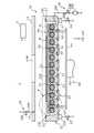
図1は、本開示の第1の実施の形態に係る半田付け装置の一例を示す概略説明図である。第1の実施の形態に係る半田付け装置1は、図1に示すように、リフロー炉として機能するものを採用することができる。この半田付け装置1では、ワークW、例えば電子部品が実装される略円盤状の半導体基板の半田付けを行うことが可能である。ここでいう半田付けには、少なくとも、ワークWとしての半導体基板上に半球状の半田バンプを形成するために予め配設された原料半田を溶融させる、ワークWとしての半導体基板上に半田バンプを生成する、あるいはクリーム半田やプリフォーム半田を介して配設された電子部品を実装することが含まれ得る。なお、以下の説明においては、その理解を容易にするために、図1における幅方向をX方向、奥行方向をY方向、及び高さ(上下)方向をZ方向と仮に定め、適宜用いるものとする。<First Embodiment>
FIG. 1 is a schematic explanatory view showing an example of a soldering apparatus according to the first embodiment of the present disclosure. As the
図2は、図1に示す半田付け装置の内部構造を示す概略平面図である。本実施の形態に係る半田付け装置1は、図1及び図2に示すように、内部に処理空間PSが形成された処理チャンバ10と、処理チャンバ10の処理空間PS内に収容されたワークWを加熱する加熱器30と、処理チャンバ10の処理空間PS内にワークWを支持するワーク支持ユニット40と、を少なくとも含むものである。また、上述した各構成要素の動作は、制御装置2によって制御されるものであって良い。なお、図2では、処理空間PS内の構成を理解しやすくするために、後述する半田付け装置1の各構成要素のうち蓋体14及びプレート41を省略し、プレート41上に載置されるワークWは破線で示している。 FIG. 2 is a schematic plan view showing the internal structure of the soldering apparatus shown in FIG. As shown in FIGS. 1 and 2, the
処理チャンバ10は、処理空間PSを画定する箱状の筐体で構成することができる。この処理チャンバ10としては、矩形状の底壁12及びこの底壁12の縁部から上方に立設する側壁13を含み、その上部が開口した処理チャンバ本体11と、処理チャンバ本体11の開口を気密に閉塞可能な蓋体14と、を少なくとも含んでいてよい。処理チャンバ10内の処理空間PSへのワークWの搬出入は、処理チャンバ本体11の開口を経由して行われ得る。 The
処理チャンバ本体11の底面を構成する底壁12は、ワークWを冷却するための冷却器20を含む。この冷却器20は、底壁12の上面から上方向に突出するように設けられ、その上面21AがワークWを冷却するための冷却面として機能し得る冷却ブロック21を少なくとも含む。冷却器20を含む処理チャンバ10の底壁12は、側壁13と共に削り出し構造で形成されていてよい。このような構成を採用することにより、本実施の形態に係る半田付け装置1は、底壁12と冷却器20とを別ユニットで構成した場合に比べて、装置を小型化することができるようになる。 The
冷却ブロック21は、図2に示すように、Y方向に延在するブロック体が、X方向に沿って複数個並ぶように配設されていてよい。換言すれば、冷却ブロック21は、X方向に沿って櫛歯状に配設されていてよい。また、この冷却ブロック21の内部には、冷媒を通過させるための冷媒通路22を配設することができる。冷却ブロック21は、その上面21Aが実質的に平坦に形成されており、この上面21AがワークWに直接又は間接的に接触することでワークWの冷却を可能とする。冷却ブロック21は、底壁12に一体的に形成されていてよい。而して、処理チャンバ10の底壁12は、冷却器20として機能している、あるいは冷却器20は、処理チャンバ10の底壁12を形成しているということができる。冷却ブロック21には、熱伝導性の高い材料、例えば銅(Cu)や銅合金で構成することができる。なお、本実施の形態においては、冷却ブロック21を櫛歯状に配設したものを例示したが、冷却ブロックのレイアウト等はこれに限定されない。 As shown in FIG. 2, the
冷媒通路22は、その内部に冷媒、例えば冷却水を通過させることで、冷却ブロック21を冷却するための通路であってよい。冷媒通路22の冷却ブロック21内の配線構造としては、例えば櫛歯状の冷却ブロック21の上面21Aに近接する位置の全てを通過するように形成することができる。この冷媒通路22は、少なくともその端部に冷媒供給口22A及び冷媒排出口22Bが1乃至複数個形成されていてよい。冷媒供給口22Aは図示しない冷媒供給源に流体的に接続されていてよく、冷媒排出口22Bは同じく図示しない冷媒回収手段に流体的に接続されていてよい。また、上述した冷媒供給源と冷媒回収手段とが共通の部材で構成されることにより、冷媒通路22を冷媒が循環する流路として構成することもできる。冷媒通路22内への冷媒の供給は、冷媒供給口22A及び冷媒排出口22Bにそれぞれ接続された冷媒供給バルブ23及び冷媒排出バルブ24を開閉することで制御され得る。なお、冷却通路22内を通過させる冷媒としては、上述の冷却水に限定されず、他の流体(例えばエチレングリコール)を単独であるいは組み合わせて用いることもできる。また、冷却通路22内に例えば80℃程度の温水を通過させれば、後述するワークWの加熱工程等における処理チャンバ10内の補助的な加温(あるいは保温)手段として機能させることもできる。 The
ここで、本実施の形態に係る冷媒通路22は、図1に示すように、その両端部が処理チャンバ10の外部まで連通していることが好ましい。このような構成とすることにより、冷媒通路22内に冷媒を供給するための各種の部材を処理チャンバ10の外部に配置することができるため、当該部材のメンテナンス等が容易に行えるようになる。また、一般に、リフロー半田付けを行う半田付け装置では、処理の過程で処理空間内が負圧状態となることがある。本実施の形態に係る半田付け装置1においても、後述する流体排出機構18が動作することで処理空間PS内を負圧状態とするため、処理空間PS内に配設された各種の部材は、処理空間PSの気密状態が維持できるよう、封止加工(シール加工)が施される。(真空)封止加工は、一般に、技術的難易度が比較的高い加工であるため、この封止加工が必要な箇所はできるだけ少ない方が、装置製造時やメンテナンス作業に必要な時間や労力を抑えることができる。この点、上述の通り冷媒通路22を処理空間PS内に配設されないようにすれば、冷媒通路22の全長にわたって上述した封止加工が必要な箇所が生じることがない。 Here, as shown in FIG. 1, it is preferable that both ends of the
処理チャンバ本体11の側壁13は、処理空間PSの周囲を包囲するように形成されていてよく、その上端部は蓋体14の下面が接触可能な実質的に平坦な面で形成されていてよい。また、この側壁13の上端面には、蓋体14に接触することで側壁13と蓋体14との間を気密に封止するシールリング13Sが配設されていてよい。 The
蓋体14は、ワークWの搬出入口として機能する処理チャンバ本体11の開口を開閉するための部材であってよい。この蓋体14は、図示しない支持機構、例えばヒンジ機構により開閉可能に支持されていてよく、また、この蓋体14には、処理チャンバ本体11の開口の閉塞状態を維持するための周知のロック機構(図示省略)が設けられていてよい。また、蓋体14の任意の位置、例えは略中央位置には、処理空間PS内を視認するための窓14Wが設けられていてよく、また、この窓14Wには透光性材料、例えば石英ガラスが嵌め込まれていてよい。なお、本実施の形態においては、蓋体14を開放することでワークWの搬出入が可能となる半田付け装置1を例示しているが、ワークWを搬出入するための具体的な構成等はこれに限定されない。 The
本実施の形態に係る半田付け装置1を用いたリフロー半田付けに際しては、処理空間PS内部に所定の流体を供給し、且つ処理空間PS内の流体を排出する動作を実行するものを例示する。そこで、本開示の半田付け装置1には、蓋体14の一部に設けられ処理空間PS内へ流体を供給可能な流体供給口15と、処理チャンバ本体11の一部に設けられ処理空間PS内の流体を処理チャンバ10の外部に排出可能な流体排出口17と、を含んでいてよい。これに関連して、処理チャンバ10は真空チャンバであってよい。なお、上述した流体供給口15や流体排出口17の配置は適宜変更することができる。 In the case of reflow soldering using the
流体供給口15には、流体供給機構16が接続されていてよい。流体供給機構16は、流体供給口15に接続された流体供給配管16Aと、流体供給配管16Aに設けられて処理空間PS内へ任意の流体を供給することを制御する流体供給バルブ16Bとを含んでいてよい。流体供給機構16により供給される流体としては、処理ガスや不活性ガス等、半田付け処理の内容に合わせて適宜選択することができる。本実施の形態に係る半田付け装置1においては、半田付け処理に際し、処理ガスとして半田の表面に形成される酸化膜を除去するための還元ガスを供給するものを例示する。この還元ガスとしては水素ガスやカルボン酸ガス等を用いることができるが、本実施の形態においてはギ酸ガスを採用したものを例示する。これに関連して、本実施の形態に係る半田付け装置1で半田付けがなされるワークWには、フラックスを含まない半田を用いることができる。本実施の形態に係る流体供給機構16には、上述したギ酸ガスと、不活性ガスとしての窒素ガスとを供給可能なものを採用している。 A
流体排出口17には、流体排出機構18が接続されていてよい。流体排出機構18は、は流体排出口17に接続された流体排出配管18Aと、流体排出配管18Aに設けられて処理空間PS内の流体を処理チャンバ10外に排出するための流体排出バルブ18B及び流体排出ポンプ18Cとを含んでいてよい。流体排出バルブ18Bは処理チャンバ10内をシールするあるいは真空破壊することが可能な真空バルブで構成することができる。また、流体排出ポンプ18Cは処理チャンバ10内が大気圧以下(例えば50~1000mTorr程度)となるよう真空引きすることが可能な真空ポンプで構成することができる。 A
加熱器30は、処理空間PS内のワークWを加熱するためのものである。本実施の形態に係る加熱器30は、熱源としての赤外線ヒータ31と、この赤外線ヒータ31を包囲する略円筒状の外管32とを含むことができる。このうち、赤外線ヒータ31は、例えば棒状に形成された複数本(図1及び図2においては12本)の赤外線(InfraRed、IR)ランプとすることができる。なお、赤外線ヒータ31の具体的な形状はこれに限定されない。 The
外管32は、少なくとも一部が透光性の材料、例えば石英ガラスで構成され、内部に赤外線ヒータ31を配設可能な複数本の円筒管とすることができる。外管32は、図1及び図2に示すように、処理チャンバ10の対向する側壁13の間を横断するように配設されていてよい。そして、その少なくとも一方の端部は、処理チャンバ10の外部に連通していてよい。これに関連して、赤外線ヒータ31は、外管32内に、外管32の処理チャンバ10の外部に連通している端部から挿入することで配設することができる。このように、赤外線ヒータ31が処理チャンバ10の外部から挿入できる構成とすることにより、赤外線ヒータ31の交換等が容易に行える。なお、本実施の形態においては、加熱器30として外管32を含むものを採用したが、本開示に係る加熱器はこのような構造に限定されず、冷却ブロックの形状等に合わせて適宜変更することができる。 The
図3は、図1のA部拡大矢視図である。外管32は、櫛歯状に配列された隣接する冷却ブロック21間の隙間に、冷却ブロック21の延在方向に沿って配設することができる。このとき、外管32の高さ位置は、図3に示すように、冷却ブロック21よりも下方に設置される。具体的には、外管32の上端の高さ位置が、冷却ブロック21の上面21Aの高さ位置よりも僅かに低くなるように設置される。外管32の上端と冷却ブロック21の上面21Aの高さの差分ΔHは、例えば数ミリ程度であってよい。これにより、冷却ブロック21とワークWとを直接又は間接的に接触させる際に加熱器30が当該接触の邪魔になることがない。 FIG. 3 is an enlarged arrow view of part A of FIG. The
加えて、隣接する冷却ブロック21間の隙間に配設される外管32は、その上側の面のみが処理空間PS内に露出し、外管32の上側の面を除く周囲の面が冷却ブロック21あるいは底壁12に当接あるいは僅かな隙間を空けて対向している。したがって、外管32の上側の面は、外管32内に挿入される赤外線ヒータ31から照射される赤外光ILを透過する照射窓33として機能することができる。これに関連して、外管32内に挿入される赤外線ヒータ31は、その照射面が照射窓33に向くように取り付けられてよい。赤外線ヒータ31から照射される赤外光ILには、近赤外線波長領域(0.75~4μm)のもの及び遠赤外線波長領域(4~1000μm)のものが含まれ得る。外管32の照射窓33を除く周囲の面、あるいは当該周囲の面に対向する冷却ブロック21あるいは底壁12の表面には、赤外線ヒータ31からの熱を遮断するための構造(断熱構造)を採用することが好ましい。具体的には、外管32の照射窓33を除く周囲の面の内側、あるいは当該周囲の面に対向する冷却ブロック21あるいは底壁12の表面に鏡面加工を施す、外管32の照射窓33を除く周囲の面と当該周囲の面に対向する冷却ブロック21あるいは底壁12の表面との間に断熱材を配設する、あるいはその両方を実施することができる。上記鏡面加工は、対応する面にクロム(Cr)やジルコニウム(Zr)等の金属を用いたメッキ加工を施すこと等により実現できる。上述した鏡面加工を採用することにより、加熱時にあっては赤外線ヒータ31からの熱放射エネルギーを効率よくワークWに伝達することができ、また冷却ブロック21の加熱を抑制できるため、ワークWの冷却に要する時間を短縮することもできる。 In addition, in the
赤外線ヒータ31から照射される赤外光ILは、図3に示すように、照射窓33から上方へ所定の照射角度θで放射状に出射し、ワークWに直接あるいは間接的に照射され得る。このときの照射角度θは適宜調整することができるが、例えば赤外線ヒータ31からZ方向に沿って延びる線を中心として80~100°の角度範囲であってよい。これに関連して、冷却ブロック21の上面21AのX方向における両端部は、赤外光ILの照射経路と重ならないように面取り21Cが施されているとよい。このように赤外光ILが冷却ブロック21に照射されないようにすることは、上述した断熱構造と同様に、冷却ブロック21の加熱を抑制し、ワークWの冷却に要する時間を短縮し得る。 As shown in FIG. 3, the infrared light IL emitted from the
ワーク支持ユニット40は、処理空間PS内に搬入されたワークWを支持すると共に、支持されたワークWの位置を調整可能なものであってよい。このワーク支持ユニット40は、処理空間PS内に搬入されたワークWを載置可能なプレート41と、プレート41を支持する1乃至複数本(図2においては4本)の昇降ピン42と、昇降ピン42に接続されて昇降ピン42を上下方向に昇降させる昇降機43とを含むことができる。 The
プレート41は、熱伝導性の高い板状体、例えば銅または銅合金を含む金属板で構成することができ、ワークWが載置可能な台として機能するものとすることができる。このプレート41は、その下面側が赤外線ヒータ31からの赤外光ILが照射される照射面、及び冷却ブロック21の上面21Aが接触する接触面となる。したがって、プレート41上に載置されたワークWは、加熱器30及び冷却器20との間にこのプレート41が介在した状態で、間接的に加熱及び冷却される。 The
昇降ピン42は、処理チャンバ本体11の底壁12を、この底壁12に設けられた昇降ピン挿通穴12Hを介して貫通するように配設された棒状の部材であってよい。この昇降ピン42は、その一端部がプレート41の下面に当接あるいは取り付けられ、他端部が昇降機43に接続されることで、プレート41を上下方向に移動させることができるものであってよい。本実施の形態においては、処理チャンバ本体11の底壁12の各隅部近傍に4つの昇降ピン挿通穴12Hが設けられており、この4つの昇降ピン挿通穴12Hに1本ずつ、昇降ピン42が挿通されたものが例示されている。なお、昇降ピン42の本数は1乃至複数本であってよく、その配置は、昇降ピン42の本数やプレート41の有無等に合わせて適宜調整することができる。また、昇降ピン挿通穴12Hは図示しない真空封止構造を含んでいてよい。 The elevating
昇降機43は、昇降ピン42を上下方向に動作させることにより、ワークWの位置を調整することが可能な装置であってよい。この昇降機43の詳細な構成については図示を省略するが、典型的には流体(水、油、空気等)を用いたピストン・シリンダ機構、ボールねじ機構、リニアモータ、あるいはソレノイドアクチュエータといった電動アクチュエータを用いた直動機構を採用することができる。本実施の形態に係る昇降機43は、その作動部分と複数本の昇降ピン42とが連結アーム44により連結されていてよい。ワーク支持ユニット40は、この昇降機43を動作させることにより、少なくとも、プレート41上に載置されたワークWを、加熱器30により加熱するための加熱位置HP(図6参照)と、冷却器20により冷却するための冷却位置CP(図6参照)との間を移動させることができる。なお、冷却位置CPは加熱位置HPの下方に位置している。 The
図4は、図1の半田付け装置に種々のワークを載置した状態を示す概略説明図である。なお、図4においては、図1に示した構成と同様の構成については同一の符号を付している。本実施の形態に係るワーク支持ユニット40は、プレート41上にワークWが載置されるものを例示したが、本開示はこれに限定されない。具体的には、例えば一の変形例としては、図4(A)に示すように、その縁部に第1のワーク固定治具50が取り付けられたワークW1を昇降ピン42上に載置する半田付け装置1Aとすることもできる。この場合には、ワークW1の下面が、赤外線ヒータ31の赤外光ILが直接照射される照射面及び冷却ブロック21の上面21Aが直接接触する接触面となる。 FIG. 4 is a schematic explanatory view showing a state in which various workpieces are placed on the soldering apparatus of FIG. 1. In FIG. 4, the same reference numerals are given to the configurations similar to those shown in FIG. 1. The
また、他の変形例としては、図4(B)に示すように、その周囲にワーク固定下治具61とワーク固定上治具62とを含む第2のワーク固定治具60が取り付けられたワークW2を、ワーク固定下治具61に設けられた略水平方向に延びる延在部63を昇降ピン42で支持するような半田付け装置1Bとすることもできる。この場合には、ワーク固定下治具61の下面が、赤外線ヒータ31の赤外光ILが直接照射される照射面、及び冷却ブロック21の上面21Aが直接接触する接触面となる。なお、上述した第2のワーク固定治具60は、ワークW2を搬送するためのキャリアとして機能するものを含む。上述のように、第1及び第2のワーク固定治具50、60のような治具を用いることで、本開示の半田付け装置で半田付けを行うことが可能なワークの大きさや形状の自由度をより高くすることができる。 Further, as another modification, as shown in FIG. 4B, a second
加えて、上述した第2のワーク固定治具60が取り付けられたワークW2のように、その高さが比較的大きいワークの半田付けを可能とするために、当該他の変形例に係る半田付け装置1Bには、処理チャンバ本体11の開口と蓋体14との間に、拡張部材14Aが設けられていてよい。この拡張部材14Aは、側壁13の上端面に沿った額縁状の部材であって、処理チャンバ10と同様の材料から構成されていてよい。このような拡張部材14Aを採用することにより、簡単に処理空間PSの大きさを変更することができるようになるため、本実施の形態に係る半田付け装置で半田付けを行うことが可能なワークの大きさや形状の自由度をさらに高めることができる。 In addition, in order to enable soldering of a work having a relatively large height, such as the work W2 to which the second
上述した半田付け装置1の各種構成要素は、これらと無線又は有線通信(図1等に模式的に点線で示している)を介して電気的に接続された制御装置2によってその動作が制御されるものであってよい。この制御装置2は、例えばシーケンサ(Programmable Logic Controller、PLC)を含むコンピュータによって構成することができる。当該コンピュータとは、少なくとも揮発性あるいは不揮発性のメモリ(例えばRAM(Random Access Memory)やHDD(Hard Disc Drive))と、CPU(Central Processing Unit)に代表されるプロセッサとを含むものとすることができる。 The operation of the various components of the
上述した構成を備える半田付け装置1によれば、冷却器20の冷却ブロック21を処理チャンバ10の底壁12に形成し、加熱器30を冷却ブロック21の上面21Aよりも下方に設置したため、処理チャンバ10、冷却器20及び加熱器30を独立したユニットとして形成した場合に比べて、構造が単純になる。これにより、半田付け装置1の部品点数を少なくすることができる。また、処理チャンバ10内の構造が単純なため、処理チャンバ10の内面に付着した汚れ(例えばワークからの揮発物やフラックス等)の清掃を短時間で行える。 According to the
また、本実施の形態に係る半田付け装置1によれば、冷却器20及び加熱器30が可動式ではなく処理チャンバ10に固定されているため、これらを動作させる際に必要な可動域を処理チャンバ内に確保する必要がなく、装置全体を小型化することができる。これに関連して、半田付け装置1を用いて半田付け処理を実行する際には、ワーク支持ユニット40によりワークWの位置をわずかに(例えば1~10mm程度)変更するだけでワークWの加熱と冷却とを行うことができ、半田付けのための各工程を円滑に進めることができる。加えて、冷却器20及び加熱器30が可動式ではないため処理空間PS内にこれらの部材の配線や管路等を配設する必要がなく、冷却器20又は加熱器30が可動式である場合に比べて、封止加工が必要な箇所が少なくて済む。これにより、処理チャンバの組み立てやメンテナンスの作業の難易度が低減でき、これらの作業に要する工数を大幅に削減することができる。 Further, according to the
次に、本実施の形態に係る半田付け製品の製造方法の一例について簡単に説明する。なお、以下の説明に際しては、半田付け製品をワークWとし、上述した半田付け装置1を用いてリフロー半田付けを実行するものを例示的に説明する。また、後述する一連の製造方法は、半田付け装置1の制御装置2によって制御され得る。 Next, an example of a method for manufacturing a soldered product according to the present embodiment will be briefly described. In the following description, a soldering product is referred to as a work W, and a device that performs reflow soldering using the above-mentioned
図5は、本開示の第1の実施の形態に係る半田付け製品の製造方法の一例を示すフローチャートである。また、図6は、図5に示す半田付け製品の製造方法を実行したときの半田付け装置の状態を示す動作説明図である。なお、図6は、説明を容易にするために半田付け装置1の一部のみを拡大した断面図で示されている。本実施の形態に係る半田付け製品の製造方法は、図5に示す各工程を含むことができる。具体的には、先ず、図6(A)に示すように、処理チャンバ10の蓋体14を開放し、処理チャンバ本体11の開口から処理空間PS内へ半田付けするワークWを搬入し、ワーク支持ユニット40のプレート41上に載置することで、ワークWをワーク支持ユニット40上に支持する(工程S11)。このとき、ワーク支持ユニット40のプレート41の高さは、例えばチャンバ本体11の開口付近に設定された受け渡し位置DPに設定されているとよい(図6(A)参照)。ただし、受け渡し位置DPはこれに限定されず、例えば後述する加熱位置HPと同様の高さ位置であってもよい。 FIG. 5 is a flowchart showing an example of a method for manufacturing a soldered product according to the first embodiment of the present disclosure. Further, FIG. 6 is an operation explanatory diagram showing a state of the soldering apparatus when the method for manufacturing the soldered product shown in FIG. 5 is executed. Note that FIG. 6 is shown as an enlarged cross-sectional view of only a part of the
ワークWがプレート41上に載置されると、次に、ワーク支持ユニット40を動作させてワークWを受け渡し位置DPの下方に設定された加熱位置HPまで移動させる(工程S12)。この移動の後、あるいはこの移動に並行して蓋体14を閉塞することで、処理チャンバ10内を気密状態とする。また、処理チャンバ10内を気密状態とした後、流体供給機構16を動作させて処理空間PS内へ窒素ガスを供給すると共に、流体排出機構18を動作させて処理空間PS内の酸素を吸引して排出しておくとよい。 When the work W is placed on the
ワーク支持ユニット40の動作によりワークWが加熱位置HPに支持される(図6(B)参照)と、加熱器30の複数の赤外線ヒータ31を動作させて、赤外光ILの照射を開始し、プレート41上に載置されたワークWを半田溶融温度(半田の種類によるが、例えば、220~400℃)まで加熱する(工程S13)。なお、前述した半田溶融温度までワークWの加熱を行う前に、ワークWを半田溶融温度よりも低い還元温度(例えば、180~260℃)まで加熱すると共に流体供給機構16を動作させて処理空間PS内へギ酸ガスを供給することで、半田表面の酸化膜を還元除去する工程を実行するとよい。 When the work W is supported by the heating position HP by the operation of the work support unit 40 (see FIG. 6B), the plurality of
加熱工程S13により半田溶融温度まで加熱されたワークWは、次に、ワーク支持ユニット40を動作させることにより、加熱位置HPの下方に設定された冷却位置CPまで移動される(工程S14)。冷却位置CPにおいては、図6(C)に示すように、プレート41の下面が冷却ブロック21の上面21Aに接触する。冷却位置CPへの移動が完了すると、制御装置2は冷却器20を動作させる、具体的には冷媒通路22内に冷媒を連続的に通過させることにより、プレート41上に載置されたワークWを半田凝固温度(例えば、300℃以下)まで冷却する(工程S15)。冷媒通路22内へ冷媒を供給する際は、冷媒供給バルブ23及び冷媒排出バルブ24を開放することにより、図5(C)に示す冷媒の流れFに沿って冷媒を循環させればよい。なお、上述した冷却工程S15においては、冷却器20による冷却を半田凝固温度以下まで実行するものとしたが、さらに低い温度、例えば処理チャンバ10外の周囲温度付近まで冷却するようにしてもよい。 The work W heated to the solder melting temperature in the heating step S13 is then moved to the cooling position CP set below the heating position HP by operating the work support unit 40 (step S14). In the cooling position CP, as shown in FIG. 6C, the lower surface of the
半田凝固温度まで冷却されることにより溶融していた半田が凝固したワークWは、次に処理チャンバ10外へ搬出され(工程S16)、他の処理装置、例えば二次的な冷却装置等へ搬送される。なお、ワークWを処理チャンバ10外へ搬出する際には、蓋体14の開放の後、あるいは蓋体14の開放に並行してワーク支持ユニット40を動作させ、ワークWを受け渡し位置DPまで上昇させるとよい。 The work W in which the solder melted by being cooled to the solder solidification temperature is solidified is then carried out of the processing chamber 10 (step S16) and transported to another processing apparatus such as a secondary cooling apparatus. Will be done. When the work W is carried out of the
以上説明した通り、本実施の形態に係る半田付け製品の製造方法によれば、半導体基板等のワークWのリフロー半田付けを行うに際し、ワークWを支持するワーク支持ユニット40を下方向にわずかに動作させるだけで、加熱位置から冷却位置へその位置を変更できる。これにより、ワークを加熱する工程から加熱したワークを冷却する工程への変更が短時間で円滑に行えるようになる。また、冷却器及び加熱器を移動させることなく一連の工程を実施することができるため、ワークの半田付けを行うために大型の半田付け装置を準備する必要がない。 As described above, according to the method for manufacturing a soldered product according to the present embodiment, when reflow soldering a work W such as a semiconductor substrate, the
<第2の実施の形態>
上述した第1の実施の形態に係る半田付け装置1においては、主に、加熱器30を冷却ブロック21の上面21Aよりも下方に設置し、この加熱器30を用いてワークWを加熱する加熱位置HPの下方に、冷却器20を用いてワークWを冷却する冷却位置CPを配設することで、半田付け装置1の小型化を実現したものを例示した。しかし、本開示の半田付け装置は、上述した構成によって半田付け装置の小型化を実現するものには限定されない。そこで、以下には本開示の第2の実施の形態として、前述の構成とは異なる構成に基づいて半田付け装置の小型化を実現したものを例示的に説明する。なお、本実施の形態に係る半田付け装置100は、上述した第1の実施の形態に係る半田付け装置1と同様に、半導体基板等からなるワークWのリフロー半田付けを行うための装置を例示的に示す。したがって、本実施の形態に係る半田付け装置100のうち、上述した第1の実施の形態に係る半田付け装置1と同様の構成については同一の符号を付してその説明を省略し、半田付け装置1とは異なる構成部分を中心に説明を行うものとする。<Second embodiment>
In the
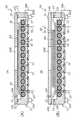
図7は、本開示の第2の実施の形態に係る半田付け装置の一例を示す概略説明図である。この図7は、図1に対応するように描かれたものといえる。本実施の形態に係る半田付け装置100は、図7に示すように、内部に処理空間PSが形成された処理チャンバ110と、処理チャンバ110の処理空間PS内に収容されたワークWを加熱する加熱器130と、処理チャンバ10の処理空間PS内にワークWを支持するワーク支持ユニット140と、を少なくとも含むものである。 FIG. 7 is a schematic explanatory view showing an example of the soldering apparatus according to the second embodiment of the present disclosure. It can be said that FIG. 7 is drawn so as to correspond to FIG. As shown in FIG. 7, the
処理チャンバ110は、処理空間PSを画定する箱状の筐体で構成することができる。この処理チャンバ110は、矩形状の底壁112及び上壁114と、この底壁112と上壁114の各縁部を繋ぐようにZ方向に延在する側壁113とを少なくとも含んでいてよい。また、側壁113の一部には、処理チャンバ110内の処理空間PSへのワークWの搬出入を行うための1乃至複数(図7においては2つ)のゲート119が設けられていてよい。これに関連して、本実施の形態に係る半田付け装置100は、異なる処理を実行するチャンバがライン上に複数個連結されて構成される(これを「インラインタイプ」と呼ぶことがある)製造システム、例えば半導体基板に各種の電子部品を実装するための製造システムの一部を構成することが可能なものであってよい。なお、本実施の形態に係る半田付け装置100の処理チャンバ110は、上述の構成に限定されるものではなく、例えば上述した第1の実施の形態に係る半田付け装置1の処理チャンバ10と同様の構成、具体的には蓋体14を開閉することでワークWの搬出入を行う構成を採用することができる。同様に、第1の実施の形態に係る半田付け装置1も、上述した処理チャンバ110と同様の構造を採用することができる。 The
処理チャンバ110の底壁112は、ワークWを冷却するための冷却器120を含む。この冷却器120は、底壁112の上面から上方向に突出するように設けられ、その上面121AがワークWを冷却するための冷却面となる冷却ブロック121を少なくとも含む。冷却ブロック121は、例えば流体排出口17が設けられた部分を除く底壁112の上面の全体を覆うように、底壁112に対して一体的に設けられていてよい。この冷却ブロック121は、その上面121Aが実質的に平坦に形成されており、この上面121AがワークWに直接又は間接的に接触することでワークWの冷却を行うものであってよい。また、この冷却ブロック121の内部には、冷媒を通過させるための冷媒通路122が配設される。その他、冷却ブロック121の材料や形成方法等については、上述した第2の実施の形態の冷却ブロック21と同様のものを採用することができる。また、冷却ブロック121の具体的な形状については、後述する加熱器130の配置や形状、あるいはワークWの形状等に合わせて適宜変更することができる。そして、冷却ブロック121の形状に合わせて、後述する冷媒通路122の引回し構造も適宜変更することができる。 The
冷媒通路122は、その内部に冷媒、例えば冷却水を通過させることで、冷却ブロック121を冷却するための通路であってよい。この冷媒通路122は、冷却ブロック121内の上面121Aに近接する位置を通過するように配設されており、この冷媒通路122内に冷媒が通過することで、周囲の冷却ブロック121を冷却するよう機能し得る。冷媒通路122の冷却ブロック121内の配線構造は、冷却ブロック121の上面121Aの全体を冷却することができれば適宜調整することができるが、例えば上面121Aに近接する位置を所定の間隔を空けて蛇行するように、あるいは上面121Aに沿って格子状に形成することができる。 The
また、この冷媒通路122の端部は、処理チャンバ110の外部に連通している。具体的には、冷媒通路122は、少なくともその端部に冷媒供給口122A及び冷媒排出口122Bが1乃至複数個形成され、冷媒供給口122A及び冷媒排出口122Bが処理チャンバ110の外部に配設されることで、冷媒通路122を処理チャンバ110の外部に連通させることができる。冷媒供給口122Aは図示しない冷媒供給源に流体的に接続されていてよく、冷媒排出口122Bは同じく図示しない冷媒回収手段に流体的に接続されていてよい。また、上述した冷媒供給源と冷媒回収手段とが共通の部材で構成されることにより、冷媒通路122を冷媒が循環する流路として構成することもできる。冷媒通路122内への冷媒の供給は、冷媒供給口122A及び冷媒排出口122Bにそれぞれ接続された冷媒供給バルブ123及び冷媒排出バルブ124を開閉することで制御され得る。 Further, the end portion of the
上述した構成とすることにより、冷媒通路122は、冷却ブロック121内、底壁112内、あるいは処理チャンバ110の外部に配線されることとなる。換言すれば、冷媒通路122は、その全長にわたって処理空間PS内に配設される部分を有しない。したがって、本実施の形態に係る半田付け装置100においては、処理空間PS内に冷媒通路122が配設されることに伴う封止加工の作業が不要となり、装置製造時やメンテナンス作業に必要な時間や労力を抑えることができる。また、冷媒通路122内に冷媒を供給するための各種の部材、例えば冷媒供給バルブ123や冷媒排出バルブ124等を処理チャンバ110の外部に配置することができるため、当該部材のメンテナンス等も容易に行えるようになる。 With the above configuration, the
加熱器130は、処理空間PS内のワークWを加熱するためのものである。本実施の形態に係る半田付け装置100が有する加熱器130は、その配置や構造に関しては特に限定されず、適宜選択することができる。図7には、加熱器130として、ワークWの上方に配設されてワークWの主に上面に熱風を供給するものを例示している。具体的には、この加熱器130は、送風機131と、加熱ヒータ132と、整流板133とを含んでいてよい。 The
送風機131は、処理空間PS内の空気を循環させてワークWに送るための部材であってよい。送風機131は、処理チャンバ110の上壁114に取り付けられた電動機と、電動機の駆動軸に取り付けられたフィンとで構成することができる。この送風機131としては、例えばシロッコファンやプロペラファンを採用することができる。また、加熱ヒータ132は、処理空間内に配設されて送風機131によって送られる処理空間PS内の気体を加熱するものであってよい。この加熱ヒータ132としては、例えばシーズヒータ等を採用することができる。さらに、整流板133は、ワークWの情報に配設され、送風機131により送られ加熱ヒータ132で加熱された熱風がワークWに吹き付けられるようにその流れを制御するものであってよい。なお、本実施の形態に係る半田付け装置100の加熱器130は上述の構成に限定されるものではなく、また、加熱器の数も1つに限定されるものではない。したがって、この加熱器130としては、上述した構成に加えて例えば第1の実施の形態に係る半田付け装置1が有する赤外線ヒータ31を含む加熱器30をさらに含んでいてもよいし、他の構成からなる加熱手段がワークWの下方や側方に単独であるいは上述のものと組み合わせて設けられていてもよい。また、加熱器130を処理空間PS内で移動可能に形成することもできる。 The
ワーク支持ユニット140は、処理空間PS内に搬入されたワークWを支持するものである。また、このワーク支持ユニット140は、支持したワークWの位置を調整可能なものとすることができる。図7には、ワーク支持ユニット140として、上述した第1の実施の形態に係る半田付け装置1のワーク支持ユニット40と同様の構成を例示している。ただし、本実施の形態に係る半田付け装置100においては、ワーク支持ユニット140として移動可能な構造を有している必要は必ずしもなく、ワークWを処理空間PS内に支持することができれば足りる。したがって、例えばワーク支持ユニット140が、冷却ブロック121の上面121Aで構成されていてもよい。この場合には、ワークWの加熱及び冷却は、冷却ブロック121の上面121Aに支持された状態で実施されることになる。 The
本実施の形態に係る半田付け装置100においても、上述した第1の実施の形態に係る半田付け装置1において示した変形、例えばワーク支持ユニット140が支持するワークWの形状や、それに伴うワーク支持ユニット140の構成要素の変更、上述した拡張部材14Aのような処理チャンバ110のサイズ調整構造の採用等が同様に適用可能であることは、当業者であれば明確に理解することができるであろう。 Also in the
上述した構成を備える半田付け装置100によれば、冷却器120が固定されているため、これを動作させる際に必要な可動域を処理チャンバ110内に確保する必要がなく、装置全体を小型化することができる。また、冷媒通路122が処理空間PS内には配線されないため、封止加工が必要な部分を少なくすることができ、製造やメンテナンスが容易な、単純な構造とすることができる。 According to the
次に、本実施の形態に係る半田付け製品の製造方法について簡単に説明する。なお、本実施の形態に係る半田付け製品の製造方法は、用いられる装置が異なるものの、一連の工程は上述した第1の実施の形態に係る半田付け製品の製造方法と類似している。そこで、本実施の形態に係る半田付け製品の製造方法の説明に際しては、図5を参酌して説明を行うものとし、一連の工程における詳細な処理内容については、第1の実施の形態に係る半田付け製品の製造方法と同様であるものとしてその説明を省略する。 Next, a method for manufacturing the soldered product according to the present embodiment will be briefly described. Although the apparatus used for manufacturing the soldered product according to the present embodiment is different, the series of steps is similar to the method for manufacturing the soldered product according to the first embodiment described above. Therefore, when explaining the method for manufacturing the soldered product according to the present embodiment, the explanation will be given with reference to FIG. 5, and the detailed processing contents in the series of steps will be related to the first embodiment. The description thereof will be omitted as it is the same as the manufacturing method of the soldered product.
本実施の形態に係る半田付け製品の製造方法は、上述した半田付け装置100を用いて実施されるものである。詳しくは、先ず、処理チャンバ110の一方のゲート119を開放し、処理空間PS内へ半田付けするワークWを搬入し、ワーク支持ユニット140のプレート41上に載置することで、ワークWをワーク支持ユニット140上に支持する(工程S11)。ワークWがプレート41上に載置されると、次に、ワーク支持ユニット140を動作させてワークWを加熱位置まで移動させる(工程S12)。この移動の後、あるいはこの移動に並行してゲート119を閉塞することで、処理チャンバ110内を気密状態とする。 The method for manufacturing a soldered product according to this embodiment is carried out using the
次に、加熱器130の送風機131及び加熱ヒータ132を動作させて、プレート41上に載置されたワークWに向けて熱風を供給し、ワークWを半田溶融温度まで加熱する(工程S13)。この加熱工程S13により半田溶融温度まで加熱されたワークWは、次に、ワーク支持ユニット140を動作させることによりプレート41が冷却ブロック121に接触する冷却位置まで移動される(工程S14)。そして、冷媒通路122内に冷媒を連続的に通過させることにより、プレート41上に載置されたワークWを半田凝固温度まで冷却する(工程S15)。半田凝固温度まで冷却されることにより溶融していた半田が凝固したワークWは、解放された他方のゲート119から処理チャンバ110外へ搬出され(工程S16)、他の処理装置、例えば二次的な冷却装置等へ搬送される。 Next, the
以上説明した通り、本実施の形態に係る半田付け製品の製造方法によれば、冷却器を移動させることなく一連の工程を実施することができるため、ワークの半田付けを行うために大型の半田付け装置を準備する必要がない。また、冷媒通路を処理空間PS内に引き回していないため、封止加工を要する部分を少なくでき、装置のメンテナンス性等を向上することができる。 As described above, according to the method for manufacturing a soldered product according to the present embodiment, a series of steps can be carried out without moving the cooler, so that a large-sized solder is used for soldering the work. There is no need to prepare a soldering device. Further, since the refrigerant passage is not routed in the processing space PS, the portion requiring sealing processing can be reduced, and the maintainability of the device can be improved.
本開示は上述した実施の形態に限定されるものではなく、本開示の主旨を逸脱しない範囲内で種々変更して実施することが可能である。そして、それらはすべて、本開示の技術思想に含まれるものである。 The present disclosure is not limited to the above-described embodiment, and various modifications can be made without departing from the gist of the present disclosure. And all of them are included in the technical idea of the present disclosure.
1、1A、1B、100 半田付け装置
2 制御装置
10、110 処理チャンバ
11 処理チャンバ本体
12、112 底壁(底面の一例)
13、113 側壁
14 蓋体
15 流体供給口
16 流体供給機構
17 流体排出口
18 流体排出機構(排出機構の一例)
20、120 冷却器
21、121 冷却ブロック
22、122 冷媒通路
22A、122A 冷媒供給口
22B、122B 冷媒排出口
30、130 加熱器
31 赤外線ヒータ
32 外管
33 照射窓
40、140 ワーク支持ユニット
41 プレート
42 昇降ピン
50 第1のワーク固定治具
60 第2のワーク固定治具
PS 処理空間
IL 赤外光
DP 受け渡し位置
HP 加熱位置
CP 冷却位置
W、W1、W2 ワーク
1, 1A, 1B, 100 Soldering device 2
13, 113
20, 120
Claims (10)
Translated fromJapanese前記冷却ブロックの上面よりも下方に設置され前記ワークを加熱する加熱器と、
前記処理チャンバ内に搬送される前記ワークを支持するワーク支持ユニットであって、前記ワーク支持ユニットは、前記加熱器を用いて前記ワークを加熱する加熱位置と、前記加熱位置の下方に位置し前記冷却器を用いて前記加熱位置で加熱された前記ワークを冷却する冷却位置との間を移動可能である、前記ワーク支持ユニットと、を備える、
半田付け装置。A processing chamber having a cooler on its bottom surface, wherein the cooler comprises a cooling block that projects upward from the bottom surface and has a cooling block that can directly or indirectly contact the work to which the upper surface is soldered. ,
A heater installed below the upper surface of the cooling block to heat the work, and
A work support unit that supports the work to be conveyed into the processing chamber, wherein the work support unit is located at a heating position for heating the work using the heater and below the heating position. A work support unit, which is movable between a cooling position for cooling the work heated at the heating position using a cooler, is provided.
Soldering equipment.
請求項1に記載の半田付け装置。The cooler further comprises the refrigerant passage, which is disposed inside the cooling block and allows the refrigerant to pass through the interior, the end of which communicates with the outside of the processing chamber.
The soldering apparatus according to claim 1.
請求項1又は請求項2に記載の半田付け装置。The heater includes an outer tube arranged so as to traverse the inside of the processing chamber, and an infrared heater inserted into the outer tube from the outside of the processing chamber.
The soldering apparatus according to claim 1 or 2.
請求項1乃至請求項3のいずれか1項に記載の半田付け装置。The work support unit includes a plate on which the work can be placed and an elevating pin which is arranged so as to penetrate the bottom surface of the processing chamber and can raise and lower the plate, and the cooling block is provided on the work. Indirect contact via the plate,
The soldering apparatus according to any one of claims 1 to 3.
請求項1乃至請求項4のいずれか1項に記載の半田付け装置。A work fixing jig attached to the work is further provided, and the cooling block can indirectly contact the work via the work fixing jig.
The soldering apparatus according to any one of claims 1 to 4.
請求項1乃至請求項5のいずれか1項に記載の半田付け装置。The processing chamber includes a processing chamber main body having the cooler on the bottom surface and an opening at the top, a lid that can close the opening airtightly, and a discharge that discharges the fluid inside the processing chamber to the outside of the processing chamber. With a mechanism,
The soldering apparatus according to any one of claims 1 to 5.
請求項1乃至請求項6のいずれか1項に記載の半田付け装置。The cooling blocks are formed in a comb shape so as to cross the processing chamber, and the heater is arranged between the adjacent cooling blocks.
The soldering apparatus according to any one of claims 1 to 6.
前記底面から上方に突出しその上面が半田付けされるワークに直接又は間接的に接触可能な冷却ブロックと、
前記冷却ブロックの内部に配設されその内部を冷媒が通過可能な冷媒通路であって、その端部が前記処理チャンバの外部に連通している、前記冷媒通路と、を備える、前記処理チャンバと、
前記ワークを加熱する加熱器と、
前記処理チャンバ内に搬送される前記ワークを支持するワーク支持ユニットと、を備える、
半田付け装置。A processing chamber having a cooler on the bottom thereof, wherein the cooler is
A cooling block that projects upward from the bottom surface and allows direct or indirect contact with the work to which the top surface is soldered.
The processing chamber comprising the refrigerant passage, which is disposed inside the cooling block and allows the refrigerant to pass through the inside, the end of which communicates with the outside of the processing chamber. ,
A heater that heats the work and
A work support unit for supporting the work to be conveyed into the processing chamber.
Soldering equipment.
加熱器を用いて前記ワークを加熱する工程と、
冷却器を用いて加熱された前記ワークを冷却する工程と、を備える、
半田付け製品の製造方法。The step of supporting the work to be soldered on the work support unit in the processing chamber of the soldering apparatus according to any one of claims 1 to 8.
The process of heating the work using a heater and
A step of cooling the work heated by using a cooler.
How to manufacture soldered products.
前記ワーク支持ユニットにより前記ワークを加熱位置に支持した状態で、前記冷却ブロックの上面よりも下方に設置された加熱器を用いて前記ワークを加熱する工程と、
前記ワーク支持ユニットにより加熱された前記ワークを前記加熱位置より低い冷却位置へ移動する工程と、
前記冷却器を用いて前記冷却位置に支持された加熱された前記ワークを冷却する工程と、を備える、
半田付け製品の製造方法。
In a step of supporting a work to be soldered onto a work support unit in a processing chamber, the processing chamber is provided with a cooler on the bottom surface thereof, and the cooler protrudes upward from the bottom surface and the upper surface thereof is soldered. With a cooling block that can be directly or indirectly contacted with the workpiece to be soldered,
A step of heating the work by using a heater installed below the upper surface of the cooling block while the work is supported at the heating position by the work support unit.
A step of moving the work heated by the work support unit to a cooling position lower than the heating position, and
A step of cooling the heated work supported at the cooling position by using the cooler.
How to manufacture soldered products.
Priority Applications (1)
| Application Number | Priority Date | Filing Date | Title |
|---|---|---|---|
| JP2021200549AJP7053939B1 (en) | 2021-12-10 | 2021-12-10 | How to manufacture soldering equipment and soldered products |
Applications Claiming Priority (1)
| Application Number | Priority Date | Filing Date | Title |
|---|---|---|---|
| JP2021200549AJP7053939B1 (en) | 2021-12-10 | 2021-12-10 | How to manufacture soldering equipment and soldered products |
Publications (2)
| Publication Number | Publication Date |
|---|---|
| JP7053939B1true JP7053939B1 (en) | 2022-04-12 |
| JP2023086198A JP2023086198A (en) | 2023-06-22 |
Family
ID=81260051
Family Applications (1)
| Application Number | Title | Priority Date | Filing Date |
|---|---|---|---|
| JP2021200549AActiveJP7053939B1 (en) | 2021-12-10 | 2021-12-10 | How to manufacture soldering equipment and soldered products |
Country Status (1)
| Country | Link |
|---|---|
| JP (1) | JP7053939B1 (en) |
Cited By (1)
| Publication number | Priority date | Publication date | Assignee | Title |
|---|---|---|---|---|
| CN115055868A (en)* | 2022-06-20 | 2022-09-16 | 中车太原机车车辆有限公司 | A liquid-cooled sidewall welding mold and method of use |
Citations (4)
| Publication number | Priority date | Publication date | Assignee | Title |
|---|---|---|---|---|
| JP2002541428A (en) | 1999-04-12 | 2002-12-03 | ジョイント、インダストリアル、プロセッサーズ、フォ−、エレクトロニクス | Heating and cooling device integrated in the reaction chamber for heat treating the substrate |
| JP2008284557A (en) | 2007-05-15 | 2008-11-27 | Shinko Seiki Co Ltd | Heating/cooling apparatus |
| WO2013161875A1 (en) | 2012-04-25 | 2013-10-31 | オリジン電気株式会社 | Soldering apparatus and method for manufacturing soldered product |
| WO2016104710A1 (en) | 2014-12-26 | 2016-06-30 | 富士電機株式会社 | Heating and cooling device |
- 2021
- 2021-12-10JPJP2021200549Apatent/JP7053939B1/enactiveActive
Patent Citations (4)
| Publication number | Priority date | Publication date | Assignee | Title |
|---|---|---|---|---|
| JP2002541428A (en) | 1999-04-12 | 2002-12-03 | ジョイント、インダストリアル、プロセッサーズ、フォ−、エレクトロニクス | Heating and cooling device integrated in the reaction chamber for heat treating the substrate |
| JP2008284557A (en) | 2007-05-15 | 2008-11-27 | Shinko Seiki Co Ltd | Heating/cooling apparatus |
| WO2013161875A1 (en) | 2012-04-25 | 2013-10-31 | オリジン電気株式会社 | Soldering apparatus and method for manufacturing soldered product |
| WO2016104710A1 (en) | 2014-12-26 | 2016-06-30 | 富士電機株式会社 | Heating and cooling device |
Cited By (1)
| Publication number | Priority date | Publication date | Assignee | Title |
|---|---|---|---|---|
| CN115055868A (en)* | 2022-06-20 | 2022-09-16 | 中车太原机车车辆有限公司 | A liquid-cooled sidewall welding mold and method of use |
Also Published As
| Publication number | Publication date |
|---|---|
| JP2023086198A (en) | 2023-06-22 |
Similar Documents
| Publication | Publication Date | Title |
|---|---|---|
| JP5864732B2 (en) | Soldering apparatus and method for manufacturing soldered product | |
| JP4860167B2 (en) | Load lock device, processing system, and processing method | |
| JP5101665B2 (en) | Substrate mounting table, substrate processing apparatus, and substrate processing system | |
| KR102200292B1 (en) | Anneal module for semiconductor wafers | |
| KR102355575B1 (en) | vacuum processing unit | |
| KR20100122893A (en) | Load lock apparatus and substrate cooling method | |
| JP7053939B1 (en) | How to manufacture soldering equipment and soldered products | |
| TW202217213A (en) | Infrared baking device and baking method of electronic part using the same | |
| US20170254592A1 (en) | Thermal treatment device | |
| JP4885023B2 (en) | Load lock device and substrate processing system | |
| JP2012195570A (en) | Substrate processing apparatus and substrate processing method | |
| CN110223933B (en) | Substrate processing device and substrate processing system | |
| TWI780820B (en) | Heat treatment apparatus | |
| JP2005277049A (en) | System and method for heat treatment | |
| KR101924675B1 (en) | Vertical heat treatment apparatus | |
| TWI801934B (en) | Heat treatment apparatus | |
| KR102811910B1 (en) | Heat treatment device, loading/unloading jig and maintenance method for heat treatment device | |
| JP2002173775A (en) | Semiconductor manufacturing apparatus and semiconductor device manufacturing method | |
| KR102258508B1 (en) | Substrate Transferring Device and Method for Treating Substrate using the Substrate Transferring Device | |
| JP2004037077A (en) | Multi-chamber heat treatment furnace | |
| JP2024084916A (en) | Heat treatment device | |
| JP2010093067A (en) | Heat treatment apparatus of substrate | |
| JP2002203803A (en) | Apparatus for heat-treating substrate | |
| KR20230099544A (en) | A substrate processing method and a substrate processing apparatus | |
| JP2022047921A (en) | Heat processing apparatus and heat processing system |
Legal Events
| Date | Code | Title | Description |
|---|---|---|---|
| A621 | Written request for application examination | Free format text:JAPANESE INTERMEDIATE CODE: A621 Effective date:20220113 | |
| A871 | Explanation of circumstances concerning accelerated examination | Free format text:JAPANESE INTERMEDIATE CODE: A871 Effective date:20220113 | |
| TRDD | Decision of grant or rejection written | ||
| A01 | Written decision to grant a patent or to grant a registration (utility model) | Free format text:JAPANESE INTERMEDIATE CODE: A01 Effective date:20220322 | |
| A61 | First payment of annual fees (during grant procedure) | Free format text:JAPANESE INTERMEDIATE CODE: A61 Effective date:20220331 | |
| R150 | Certificate of patent or registration of utility model | Ref document number:7053939 Country of ref document:JP Free format text:JAPANESE INTERMEDIATE CODE: R150 | |
| R250 | Receipt of annual fees | Free format text:JAPANESE INTERMEDIATE CODE: R250 |