JP7053739B2 - Syringe with rolling diaphragm - Google Patents
Syringe with rolling diaphragmDownload PDFInfo
- Publication number
- JP7053739B2 JP7053739B2JP2020138033AJP2020138033AJP7053739B2JP 7053739 B2JP7053739 B2JP 7053739B2JP 2020138033 AJP2020138033 AJP 2020138033AJP 2020138033 AJP2020138033 AJP 2020138033AJP 7053739 B2JP7053739 B2JP 7053739B2
- Authority
- JP
- Japan
- Prior art keywords
- rolling diaphragm
- plunger
- side wall
- pressure jacket
- fluid
- Prior art date
- Legal status (The legal status is an assumption and is not a legal conclusion. Google has not performed a legal analysis and makes no representation as to the accuracy of the status listed.)
- Active
Links
Images


Classifications
- A—HUMAN NECESSITIES
- A61—MEDICAL OR VETERINARY SCIENCE; HYGIENE
- A61M—DEVICES FOR INTRODUCING MEDIA INTO, OR ONTO, THE BODY; DEVICES FOR TRANSDUCING BODY MEDIA OR FOR TAKING MEDIA FROM THE BODY; DEVICES FOR PRODUCING OR ENDING SLEEP OR STUPOR
- A61M5/00—Devices for bringing media into the body in a subcutaneous, intra-vascular or intramuscular way; Accessories therefor, e.g. filling or cleaning devices, arm-rests
- A61M5/14—Infusion devices, e.g. infusing by gravity; Blood infusion; Accessories therefor
- A61M5/142—Pressure infusion, e.g. using pumps
- A61M5/145—Pressure infusion, e.g. using pumps using pressurised reservoirs, e.g. pressurised by means of pistons
- A—HUMAN NECESSITIES
- A61—MEDICAL OR VETERINARY SCIENCE; HYGIENE
- A61M—DEVICES FOR INTRODUCING MEDIA INTO, OR ONTO, THE BODY; DEVICES FOR TRANSDUCING BODY MEDIA OR FOR TAKING MEDIA FROM THE BODY; DEVICES FOR PRODUCING OR ENDING SLEEP OR STUPOR
- A61M5/00—Devices for bringing media into the body in a subcutaneous, intra-vascular or intramuscular way; Accessories therefor, e.g. filling or cleaning devices, arm-rests
- A61M5/178—Syringes
- A61M5/31—Details
- A61M5/315—Pistons; Piston-rods; Guiding, blocking or restricting the movement of the rod or piston; Appliances on the rod for facilitating dosing ; Dosing mechanisms
- A61M5/31511—Piston or piston-rod constructions, e.g. connection of piston with piston-rod
- A61M5/31513—Piston constructions to improve sealing or sliding
- A—HUMAN NECESSITIES
- A61—MEDICAL OR VETERINARY SCIENCE; HYGIENE
- A61M—DEVICES FOR INTRODUCING MEDIA INTO, OR ONTO, THE BODY; DEVICES FOR TRANSDUCING BODY MEDIA OR FOR TAKING MEDIA FROM THE BODY; DEVICES FOR PRODUCING OR ENDING SLEEP OR STUPOR
- A61M5/00—Devices for bringing media into the body in a subcutaneous, intra-vascular or intramuscular way; Accessories therefor, e.g. filling or cleaning devices, arm-rests
- A61M5/14—Infusion devices, e.g. infusing by gravity; Blood infusion; Accessories therefor
- A61M5/142—Pressure infusion, e.g. using pumps
- A61M5/145—Pressure infusion, e.g. using pumps using pressurised reservoirs, e.g. pressurised by means of pistons
- A61M5/14586—Pressure infusion, e.g. using pumps using pressurised reservoirs, e.g. pressurised by means of pistons pressurised by means of a flexible diaphragm
- A—HUMAN NECESSITIES
- A61—MEDICAL OR VETERINARY SCIENCE; HYGIENE
- A61M—DEVICES FOR INTRODUCING MEDIA INTO, OR ONTO, THE BODY; DEVICES FOR TRANSDUCING BODY MEDIA OR FOR TAKING MEDIA FROM THE BODY; DEVICES FOR PRODUCING OR ENDING SLEEP OR STUPOR
- A61M5/00—Devices for bringing media into the body in a subcutaneous, intra-vascular or intramuscular way; Accessories therefor, e.g. filling or cleaning devices, arm-rests
- A61M5/178—Syringes
- A61M5/24—Ampoule syringes, i.e. syringes with needle for use in combination with replaceable ampoules or carpules, e.g. automatic
- A61M5/2422—Ampoule syringes, i.e. syringes with needle for use in combination with replaceable ampoules or carpules, e.g. automatic using emptying means to expel or eject media, e.g. pistons, deformation of the ampoule, or telescoping of the ampoule
- A61M5/2425—Ampoule syringes, i.e. syringes with needle for use in combination with replaceable ampoules or carpules, e.g. automatic using emptying means to expel or eject media, e.g. pistons, deformation of the ampoule, or telescoping of the ampoule by compression of deformable ampoule or carpule wall
- A—HUMAN NECESSITIES
- A61—MEDICAL OR VETERINARY SCIENCE; HYGIENE
- A61M—DEVICES FOR INTRODUCING MEDIA INTO, OR ONTO, THE BODY; DEVICES FOR TRANSDUCING BODY MEDIA OR FOR TAKING MEDIA FROM THE BODY; DEVICES FOR PRODUCING OR ENDING SLEEP OR STUPOR
- A61M5/00—Devices for bringing media into the body in a subcutaneous, intra-vascular or intramuscular way; Accessories therefor, e.g. filling or cleaning devices, arm-rests
- A61M5/178—Syringes
- A61M5/31—Details
- A—HUMAN NECESSITIES
- A61—MEDICAL OR VETERINARY SCIENCE; HYGIENE
- A61M—DEVICES FOR INTRODUCING MEDIA INTO, OR ONTO, THE BODY; DEVICES FOR TRANSDUCING BODY MEDIA OR FOR TAKING MEDIA FROM THE BODY; DEVICES FOR PRODUCING OR ENDING SLEEP OR STUPOR
- A61M5/00—Devices for bringing media into the body in a subcutaneous, intra-vascular or intramuscular way; Accessories therefor, e.g. filling or cleaning devices, arm-rests
- A61M5/14—Infusion devices, e.g. infusing by gravity; Blood infusion; Accessories therefor
- A61M5/142—Pressure infusion, e.g. using pumps
- A61M5/145—Pressure infusion, e.g. using pumps using pressurised reservoirs, e.g. pressurised by means of pistons
- A61M2005/14513—Pressure infusion, e.g. using pumps using pressurised reservoirs, e.g. pressurised by means of pistons with secondary fluid driving or regulating the infusion
- A—HUMAN NECESSITIES
- A61—MEDICAL OR VETERINARY SCIENCE; HYGIENE
- A61M—DEVICES FOR INTRODUCING MEDIA INTO, OR ONTO, THE BODY; DEVICES FOR TRANSDUCING BODY MEDIA OR FOR TAKING MEDIA FROM THE BODY; DEVICES FOR PRODUCING OR ENDING SLEEP OR STUPOR
- A61M5/00—Devices for bringing media into the body in a subcutaneous, intra-vascular or intramuscular way; Accessories therefor, e.g. filling or cleaning devices, arm-rests
- A61M5/14—Infusion devices, e.g. infusing by gravity; Blood infusion; Accessories therefor
- A61M5/142—Pressure infusion, e.g. using pumps
- A61M5/145—Pressure infusion, e.g. using pumps using pressurised reservoirs, e.g. pressurised by means of pistons
- A61M5/1452—Pressure infusion, e.g. using pumps using pressurised reservoirs, e.g. pressurised by means of pistons pressurised by means of pistons
- A61M5/14546—Front-loading type injectors
- A61M2005/14553—Front-loading type injectors comprising a pressure jacket
- A—HUMAN NECESSITIES
- A61—MEDICAL OR VETERINARY SCIENCE; HYGIENE
- A61M—DEVICES FOR INTRODUCING MEDIA INTO, OR ONTO, THE BODY; DEVICES FOR TRANSDUCING BODY MEDIA OR FOR TAKING MEDIA FROM THE BODY; DEVICES FOR PRODUCING OR ENDING SLEEP OR STUPOR
- A61M2205/00—General characteristics of the apparatus
- A61M2205/36—General characteristics of the apparatus related to heating or cooling
- A—HUMAN NECESSITIES
- A61—MEDICAL OR VETERINARY SCIENCE; HYGIENE
- A61M—DEVICES FOR INTRODUCING MEDIA INTO, OR ONTO, THE BODY; DEVICES FOR TRANSDUCING BODY MEDIA OR FOR TAKING MEDIA FROM THE BODY; DEVICES FOR PRODUCING OR ENDING SLEEP OR STUPOR
- A61M5/00—Devices for bringing media into the body in a subcutaneous, intra-vascular or intramuscular way; Accessories therefor, e.g. filling or cleaning devices, arm-rests
- A61M5/14—Infusion devices, e.g. infusing by gravity; Blood infusion; Accessories therefor
- A61M5/142—Pressure infusion, e.g. using pumps
- A61M5/145—Pressure infusion, e.g. using pumps using pressurised reservoirs, e.g. pressurised by means of pistons
- A61M5/1452—Pressure infusion, e.g. using pumps using pressurised reservoirs, e.g. pressurised by means of pistons pressurised by means of pistons
- A61M5/14546—Front-loading type injectors
- A—HUMAN NECESSITIES
- A61—MEDICAL OR VETERINARY SCIENCE; HYGIENE
- A61M—DEVICES FOR INTRODUCING MEDIA INTO, OR ONTO, THE BODY; DEVICES FOR TRANSDUCING BODY MEDIA OR FOR TAKING MEDIA FROM THE BODY; DEVICES FOR PRODUCING OR ENDING SLEEP OR STUPOR
- A61M5/00—Devices for bringing media into the body in a subcutaneous, intra-vascular or intramuscular way; Accessories therefor, e.g. filling or cleaning devices, arm-rests
- A61M5/14—Infusion devices, e.g. infusing by gravity; Blood infusion; Accessories therefor
- A61M5/142—Pressure infusion, e.g. using pumps
- A61M5/145—Pressure infusion, e.g. using pumps using pressurised reservoirs, e.g. pressurised by means of pistons
- A61M5/1452—Pressure infusion, e.g. using pumps using pressurised reservoirs, e.g. pressurised by means of pistons pressurised by means of pistons
- A61M5/14566—Pressure infusion, e.g. using pumps using pressurised reservoirs, e.g. pressurised by means of pistons pressurised by means of pistons with a replaceable reservoir for receiving a piston rod of the pump
- A—HUMAN NECESSITIES
- A61—MEDICAL OR VETERINARY SCIENCE; HYGIENE
- A61M—DEVICES FOR INTRODUCING MEDIA INTO, OR ONTO, THE BODY; DEVICES FOR TRANSDUCING BODY MEDIA OR FOR TAKING MEDIA FROM THE BODY; DEVICES FOR PRODUCING OR ENDING SLEEP OR STUPOR
- A61M5/00—Devices for bringing media into the body in a subcutaneous, intra-vascular or intramuscular way; Accessories therefor, e.g. filling or cleaning devices, arm-rests
- A61M5/14—Infusion devices, e.g. infusing by gravity; Blood infusion; Accessories therefor
- A61M5/142—Pressure infusion, e.g. using pumps
- A61M5/145—Pressure infusion, e.g. using pumps using pressurised reservoirs, e.g. pressurised by means of pistons
- A61M5/14586—Pressure infusion, e.g. using pumps using pressurised reservoirs, e.g. pressurised by means of pistons pressurised by means of a flexible diaphragm
- A61M5/14593—Pressure infusion, e.g. using pumps using pressurised reservoirs, e.g. pressurised by means of pistons pressurised by means of a flexible diaphragm the diaphragm being actuated by fluid pressure
- A—HUMAN NECESSITIES
- A61—MEDICAL OR VETERINARY SCIENCE; HYGIENE
- A61M—DEVICES FOR INTRODUCING MEDIA INTO, OR ONTO, THE BODY; DEVICES FOR TRANSDUCING BODY MEDIA OR FOR TAKING MEDIA FROM THE BODY; DEVICES FOR PRODUCING OR ENDING SLEEP OR STUPOR
- A61M5/00—Devices for bringing media into the body in a subcutaneous, intra-vascular or intramuscular way; Accessories therefor, e.g. filling or cleaning devices, arm-rests
- A61M5/178—Syringes
- A61M5/31—Details
- A61M5/315—Pistons; Piston-rods; Guiding, blocking or restricting the movement of the rod or piston; Appliances on the rod for facilitating dosing ; Dosing mechanisms
- A61M5/31511—Piston or piston-rod constructions, e.g. connection of piston with piston-rod
- A61M5/31515—Connection of piston with piston rod
Landscapes
- Health & Medical Sciences (AREA)
- Vascular Medicine (AREA)
- Engineering & Computer Science (AREA)
- Anesthesiology (AREA)
- Biomedical Technology (AREA)
- Heart & Thoracic Surgery (AREA)
- Hematology (AREA)
- Life Sciences & Earth Sciences (AREA)
- Animal Behavior & Ethology (AREA)
- General Health & Medical Sciences (AREA)
- Public Health (AREA)
- Veterinary Medicine (AREA)
- Physics & Mathematics (AREA)
- Fluid Mechanics (AREA)
- Infusion, Injection, And Reservoir Apparatuses (AREA)
Description
Translated fromJapanese[出願の相互参照]
本出願は、「Syringe With Rolling Diaphragm」という名称の2014年4月25日に出願された米国仮特許出願第61/984,386号明細書、および「Syringe With Rolling Diaphragm」という名称の2014年3月1日に出願された米国仮特許出願第61/987,086号明細書に対する優先権を主張し、それらの開示内容は全体として参照により本明細書に組み込まれる。[Cross-reference of applications]
This application applies to US Provisional Patent Application No. 61 / 984,386, filed April 25, 2014, entitled "Syringe With Rolling Diaphragm", and 20143, entitled "Syringe With Rolling Diaphragm". Claims priority over US Provisional Patent Application No. 61 / 987,086 filed on 1st May, the disclosure of which is incorporated herein by reference in its entirety.
本開示は、医療分野において使用されるシリンジに関し、より詳細には、選択的にシリンジに流体を充填しかつシリンジから流体を排出するためのローリングダイヤフラムを含む、医療分野で使用されるシリンジに関する。 The present disclosure relates to syringes used in the medical field, and more particularly to syringes used in the medical field, including a rolling diaphragm for selectively filling the syringe with fluid and draining the fluid from the syringe.
多くの医療診断および治療処置において、内科医等の医師は、患者に1種または複数種の医療流体を注入する。近年、造影剤溶液(単に「造影剤」と呼ばれることが多い)、生理食塩水等の洗浄剤および他の医療流体等、医療流体を加圧注入するための多数のインジェクタ作動型シリンジおよび流体注入器(インジェクタ)が、血管造影法、コンピュータ断層撮影法(CT)、超音波、磁気共鳴画像法(MRI)、ポジトロン断層法(PET)および他の分子イメージング処置等の処置において使用されるために開発されてきた。一般に、これらの流体注入器は、予め設定された圧力および/または流量で予め設定された量の流体を送達するように設計されている。 In many medical diagnostic and therapeutic procedures, physicians such as physicians inject one or more medical fluids into a patient. In recent years, numerous injector-actuated syringes and fluid injections for pressurized injection of medical fluids such as contrast agent solutions (often referred to simply as "contrast agents"), cleaning agents such as physiological saline and other medical fluids. To be used in procedures such as angiography, computer tomography (CT), ultrasound, magnetic resonance imaging (MRI), positron emission tomography (PET) and other molecular imaging procedures. Has been developed. In general, these fluid injectors are designed to deliver a preset amount of fluid at a preset pressure and / or flow rate.
注入処置によっては、医師は、管または他の流体送達接続部に接続されたカテーテルまたは針を患者の静脈または動脈のいずれかの中に配置する。カテーテルまたは管は、手動流体注入機構または自動流体注入機構のいずれかに接続される。自動流体注入機構は、通常、たとえば少なくとも1つの電動式リニアピストンを有する少なくとも1つの流体注入器に接続された少なくとも1つのシリンジを含む。少なくとも1つのシリンジは、たとえば、造影剤源および/または洗浄流体源を含む。医師は、流体注入器の電子制御システムに、一定量の造影剤および/または生理食塩水と各々に対する一定の注入速度とに関する設定を入力する。 Depending on the infusion procedure, the physician places a catheter or needle connected to a tube or other fluid delivery connection into either the patient's vein or artery. The catheter or tube is connected to either a manual fluid infusion mechanism or an automatic fluid infusion mechanism. The automatic fluid injection mechanism typically includes at least one syringe connected to at least one fluid injector having, for example, at least one electric linear piston. The at least one syringe comprises, for example, a contrast agent source and / or a wash fluid source. The physician inputs to the electronic control system of the fluid injector the settings for a constant amount of contrast and / or saline and a constant infusion rate for each.
注入された造影剤および/または生理食塩水は、患者の腕または鼠蹊部等、患者の体内に挿入されたカテーテルまたは針を通して、患者の血管系に送達される。1回分の造影剤をボーラスと呼ぶ。所望の部位に造影剤のボーラスが送達されると、その領域が、血管造影イメージングまたはスキャン、CT、超音波、MRI、PETおよび他の分子イメージング処置等、従来のイメージング技法を用いて画像化される。造影剤の存在は、周囲組織の背景に対して明確に可視化される。 The injected contrast agent and / or saline is delivered to the patient's vasculature through a catheter or needle inserted into the patient's body, such as the patient's arm or groin. A single dose of contrast medium is called a bolus. Once the contrast bolus is delivered to the desired site, the area is imaged using conventional imaging techniques such as angiographic imaging or scanning, CT, ultrasound, MRI, PET and other molecular imaging procedures. To. The presence of contrast agent is clearly visible to the background of the surrounding tissue.
医療処置において使用するために、多くのインジェクタ作動型シリンジおよび電動注入器が開発された。通常、注入器は、シリンジプランジャに接続するピストン等の駆動部材を有する。シリンジは、一般に、剛性バレルを含み、そのバレル内にシリンジプランジャが摺動可能に配置されている。駆動部材は、流体をシリンジバレル内に吸引するかまたはシリンジバレルから流体を送達するために、バレルの長手方向に対して近位方向および/または遠位方向にプランジャを駆動する。 Many injector-actuated syringes and electric injectors have been developed for use in medical procedures. Usually, the injector has a driving member such as a piston that connects to the syringe plunger. Syringes generally include a rigid barrel in which a syringe plunger is slidably disposed. The drive member drives the plunger proximally and / or distally to the longitudinal direction of the barrel in order to aspirate the fluid into or deliver the fluid from the barrel barrel.
医療分野において使用されるシリンジは、通常、使い捨てであり、1回使用した後に廃棄されることは周知である。使い捨てシリンジは、通常、射出成形等の大量生産法によって作製されるため、それらの製造に関連する材料および精度のために比較的高価である。したがって、注入処置を容易にするシリンジの改善された設計を開発することが依然として望ましい。 It is well known that syringes used in the medical field are usually disposable and are discarded after one use. Disposable syringes are usually made by mass production methods such as injection molding and are therefore relatively expensive due to the materials and accuracy associated with their manufacture. Therefore, it is still desirable to develop an improved design of the syringe that facilitates the infusion procedure.
本開示は、概して、シリンジアセンブリと、シリンジアセンブリを形成する方法とに関する。シリンジアセンブリは、流体送達用途において有用であり得る。 The present disclosure generally relates to a syringe assembly and a method of forming the syringe assembly. Syringe assemblies can be useful in fluid delivery applications.
一態様では、医療流体を受け入れるローリングダイヤフラムは、プランジャと係合する端壁を有する近位端と、圧力ジャケットの貫通孔内に受け入れられる遠位端であって、ノズルを有する遠位端とを有することができる。ローリングダイヤフラムは、長手方向軸に沿って近位端と遠位端との間に延在する側壁をさらに含むことができる。側壁および端壁のうちの少なくとも一方の少なくとも一部が不均一な厚さを有する。側壁の少なくとも一部は、可撓性を有することができ、かつプランジャによって作用されるとそれ自体の上で転動し、それにより、プランジャが近位端から遠位端に前進される際に、折畳み領域における側壁の外面が半径方向内側方向に折り畳まれ、およびプランジャが近位端から遠位端に後退される際に、折畳み領域における側壁の外面が半径方向外側方向に広げられる。 In one aspect, the rolling diaphragm that receives the medical fluid has a proximal end with an end wall that engages the plunger and a distal end that is received within the through hole of the pressure jacket and has a nozzle. Can have. The rolling diaphragm can further include a side wall extending between the proximal and distal ends along the longitudinal axis. At least a portion of the sidewall and end wall has a non-uniform thickness. At least a portion of the sidewall can be flexible and rolls on itself when acted upon by the plunger, thereby advancing the plunger from the proximal end to the distal end. , The outer surface of the side wall in the folded area is folded radially inwardly, and the outer surface of the side wall in the folded area is expanded radially outward as the plunger retracts from the proximal end to the distal end.
別の態様によれば、端壁は、連続的に厚さが増大する遠位に延在する傾斜面に遷移する丸みがつけられた折縁を有することができる。端壁は、傾斜面の中心領域から近位に突出するプランジャ係合部分を有することができる。端壁は、プランジャ係合部分から丸みが付けられた折縁に向かって半径方向外側に突出する1つまたは複数のリブを有することができる。ローリングダイヤフラムは、近位端から遠位端に向かって細くなる円錐形状を有することができる。円錐形状は、近位端から遠位端に向かって連続的にまたは不連続に細くなることができる。近位端は、プランジャと係合すると、第1凸状形態から第2凹状形態に反転することができる。側壁の外面は、側壁内に半径方向内側に窪みが付けられた1つまたは複数の溝を有することができる。側壁の外面は、側壁から半径方向外側に突出する1つまたは複数の突起を有することができる。いくつかの態様では、ローリングダイヤフラムは、球形状または楕円形状を有することができる。ローリングダイヤフラムは、長手方向軸に沿って延在する長軸と、長手方向軸に対して垂直に延在する短軸とを有する楕円形断面を有することができる。 According to another aspect, the end wall can have a rounded fold that transitions to a distally extending slanted surface that continuously increases in thickness. The end wall can have a plunger engagement portion that projects proximally from the central region of the slope. The end wall can have one or more ribs protruding radially outward from the plunger engaging portion towards the rounded fold edge. The rolling diaphragm can have a conical shape that tapers from the proximal end to the distal end. The conical shape can taper continuously or discontinuously from the proximal end to the distal end. The proximal end can be inverted from the first convex form to the second concave form when engaged with the plunger. The outer surface of the side wall can have one or more grooves with a radial inward recess in the side wall. The outer surface of the side wall can have one or more protrusions that project radially outward from the side wall. In some embodiments, the rolling diaphragm can have a spherical or oval shape. The rolling diaphragm can have an elliptical cross section with a major axis extending along the longitudinal axis and a minor axis extending perpendicular to the longitudinal axis.
別の態様によれば、ローリングダイヤフラムは、ローリングダイヤフラムのおよその長手方向中間点から遠位端まで延在する第1部分と、第1部分に形状が相補的であり第1部分から近位端まで延在する第2部分とを有することができる。ローリングダイヤフラムは、側壁の外側部分の少なくとも一部を包囲する圧力スリーブをさらに有することができる。圧力スリーブは、圧力スリーブの側壁を通って延在する1つまたは複数の開口部を有することができる。1つまたは複数の開口部を真空源に接続することができる。ローリングダイヤフラムのおよその中間点の遠位の第1部分が、第1内径を有することができ、ローリングダイヤフラムのおよその中間点の近位の第2部分が、第2内径を有することができる。第1内径を第2内径より大きくすることができる。ローリングダイヤフラムのおよその中間点の遠位の側壁の第1部分が、第1厚さを有することができ、ローリングダイヤフラムのおよその中間点の近位の側壁の第2部分が、第2厚さを有することができる。第1厚さを第2厚さより大きくすることができる。近位端は、近位端と一体的に形成された剛性プランジャを有することができる。近位端にプランジャをオーバモールドすることができる。側壁の外面は、剛性外側シェルと接触することができる。ローリングダイヤフラムの側壁は、プランジャの近位端から遠位端への前進中に側壁がそれ自体の上で転動する際に、剛性外側シェルから分離することができる。ローリングダイヤフラムの側壁の外面の少なくとも一部は、接着剤により剛性外側シェルに接着される。接着剤は、感圧接着剤であり得る。側壁の外面の少なくとも一部は、プランジャの近位端から遠位端への前進中に側壁の外面をプランジャに付着する接着剤を有することができる。 According to another aspect, the rolling diaphragm has a first portion extending from an approximately longitudinal midpoint to the distal end of the rolling diaphragm and a shape complementary to the first portion and from the first portion to the proximal end. It can have a second portion that extends to. The rolling diaphragm may further have a pressure sleeve that surrounds at least a portion of the outer portion of the sidewall. The pressure sleeve can have one or more openings extending through the sidewalls of the pressure sleeve. One or more openings can be connected to the vacuum source. The first portion distal to the approximate midpoint of the rolling diaphragm can have a first inner diameter, and the second portion proximal to the approximate midpoint of the rolling diaphragm can have a second inner diameter. The first inner diameter can be made larger than the second inner diameter. The first portion of the side wall distal to the approximate midpoint of the rolling diaphragm can have a first thickness, and the second portion of the proximal sidewall of the approximate midpoint of the rolling diaphragm can have a second thickness. Can have. The first thickness can be made larger than the second thickness. The proximal end can have a rigid plunger formed integrally with the proximal end. The plunger can be overmolded to the proximal end. The outer surface of the side wall can be in contact with the rigid outer shell. The sidewall of the rolling diaphragm can be separated from the rigid outer shell as the sidewall rolls over itself during advancement from the proximal end to the distal end of the plunger. At least a portion of the outer surface of the side wall of the rolling diaphragm is glued to the rigid outer shell. The adhesive can be a pressure sensitive adhesive. At least a portion of the outer surface of the sidewall can have an adhesive that adheres the outer surface of the sidewall to the plunger during advance from the proximal end to the distal end of the plunger.
別の態様によれば、側壁は、近位端と遠位端との間に不均一な厚さを有することができる。側壁の近位部分は、側壁の遠位部分より厚い側壁厚さを有することができる。側壁の近位部分は、側壁の遠位部分より薄い側壁厚さを有することができる。熱収縮層が、側壁の外面の少なくとも一部を包囲することができる。プランジャがローリングダイヤフラムの近位端から遠位端に前進される際に、折畳み領域は側壁の転動を開始することができる。側壁の外面は、複数のタブを有することができ、各タブは、側壁の外面に接続された第1端部と、第1端部に対して半径方向外側に突出する第2端部とを有する。複数のタブの各々は、半径方向に偏向可能であり得る。ローリングダイヤフラムの側壁は、ローリングダイヤフラムの内部容積内の液体の存在を示す1つまたは複数のしるしを有することができる。ローリングダイヤフラムの内部を、患者に送達される医療流体で予め充填することができる。ローリングダイヤフラムの内部を、患者に送達される流体源からの医療流体で充填することができる。 According to another aspect, the sidewall can have a non-uniform thickness between the proximal and distal ends. The proximal portion of the sidewall can have a thicker sidewall thickness than the distal portion of the sidewall. The proximal portion of the sidewall can have a thinner sidewall thickness than the distal portion of the sidewall. A heat shrink layer can surround at least a portion of the outer surface of the sidewall. As the plunger is advanced from the proximal end to the distal end of the rolling diaphragm, the folding area can initiate roll of the sidewall. The outer surface of the side wall can have a plurality of tabs, each tab having a first end connected to the outer surface of the side wall and a second end protruding radially outward with respect to the first end. Have. Each of the tabs can be radially deflectable. The sidewall of the rolling diaphragm can have one or more markings indicating the presence of liquid within the internal volume of the rolling diaphragm. The interior of the rolling diaphragm can be prefilled with the medical fluid delivered to the patient. The interior of the rolling diaphragm can be filled with medical fluid from a fluid source delivered to the patient.
別の態様によれば、流体送達システムは、少なくとも1つの往復動作可能なピストンを有する流体注入器と、ピストンに動作可能に接続可能なプランジャと、流体注入器に解除可能に接続可能な圧力ジャケットと、圧力ジャケットの貫通孔内に配置されたローリングダイヤフラムとを有する。ローリングダイヤフラムは、プランジャと係合する端壁を備えた近位端と、圧力ジャケットの遠位端において受け入れられるように構成された遠位端と、長手方向軸に沿ってローリングダイヤフラムの近位端と遠位端との間に延在する側壁とを有することができる。端壁および側壁の少なくとも一部のうちの少なくとも一方が不均一な厚さを有する。ローリングダイヤフラムの側壁は、可撓性を有し、かつそれ自体の上で転動するように構成され得、それにより、プランジャがローリングダイヤフラムの近位端から遠位端に前進される際に、折畳み領域における側壁の外面が半径方向内側方向に折り畳まれ、およびプランジャがローリングダイヤフラムの近位端から遠位端に後退される際に、折畳み領域における側壁の外面が半径方向外側方向に広げられる。 According to another aspect, the fluid delivery system comprises a fluid injector having at least one reciprocating piston, a plunger operably connectable to the piston, and a pressure jacket detachably connectable to the fluid injector. And a rolling diaphragm disposed in the through hole of the pressure jacket. The rolling diaphragm is a proximal end with an end wall that engages the plunger, a distal end configured to be accepted at the distal end of the pressure jacket, and a proximal end of the rolling diaphragm along the longitudinal axis. Can have a sidewall extending between the and the distal end. At least one of the end walls and at least a portion of the sidewall has a non-uniform thickness. The sidewalls of the rolling diaphragm may be configured to be flexible and roll on itself, whereby the plunger is advanced from the proximal end to the distal end of the rolling diaphragm. The outer surface of the side wall in the folded area is expanded radially outward as the outer surface of the side wall in the folded area is folded radially inward and the plunger retracts from the proximal end to the distal end of the rolling diaphragm.
別の態様によれば、プランジャは、プランジャの本体の周囲で半径方向に延在するスカートを有することができる。スカートの外径は、プランジャが遠位方向に前進される際に、スカートが、ローリングダイヤフラムの側壁に対して圧縮されてローリングダイヤフラムの内部から流体を排出するような寸法とすることができる。プランジャは、流体充填空洞を有することができ、流体充填空洞の少なくとも一部に、往復移動可能なピストンが延在している。ローリングダイヤフラムの近位端と一体的にプランジャを形成することができる。プランジャは、プランジャの遠位端に成形された溝を有することができる。ローリングダイヤフラムの近位端は、プランジャの溝内に挿入されてそこに保持されるように構成された突起を有することができる。溝は、T字型であり得る。プランジャは、流体注入器のピストンに、ピストンによって往復駆動されるように解除可能に接続する接続インタフェースを有することができる。プランジャは、第1ねじ切り部材を有することができ、ローリングダイヤフラムの近位端は第2ねじ切り部材を有することができる。プランジャの第1ねじ切り部材は、ローリングダイヤフラムの第2ねじ切り部材と解除可能に接続可能であり得る。 According to another aspect, the plunger can have a skirt extending radially around the body of the plunger. The outer diameter of the skirt can be sized so that as the plunger is advanced distally, the skirt is compressed against the side wall of the rolling diaphragm to drain fluid from inside the rolling diaphragm. The plunger can have a fluid-filled cavity, with at least a portion of the fluid-filled cavity extending with a reciprocating piston. A plunger can be formed integrally with the proximal end of the rolling diaphragm. The plunger can have a groove formed at the distal end of the plunger. The proximal end of the rolling diaphragm can have a protrusion configured to be inserted into and retained in the groove of the plunger. The groove can be T-shaped. The plunger can have a connection interface that is detachably connected to the piston of the fluid injector so that it is driven back and forth by the piston. The plunger can have a first threading member and the proximal end of the rolling diaphragm can have a second threading member. The first threaded member of the plunger may be releasably connectable to the second threaded member of the rolling diaphragm.
別の態様では、プランジャの遠位端は、1つまたは複数の半径方向拡張可能リブを有することができる。プランジャの遠位端は、1つまたは複数の回転可能要素を有することができ、第1方向における1つまたは複数の回転可能要素の回転により、半径方向拡張可リブの拡張がもたらされ、第2方向における1つまたは複数の回転可能要素の回転により、半径方向拡張可能リブの後退がもたらされる。プランジャの遠位端は、ローリングダイヤフラムの近位端の突起を受け入れるように構成されたスロットを有することができる。ローリングダイヤフラムの近位端の突起がスロットに挿入された後、プランジャを回転させて、ローリングダイヤフラムにプランジャを係止することができる。プランジャは、互いに対して入れ子式の向きで配置された複数の同心要素を有することができる。複数の同心要素の各々は、近位方向または遠位方向に独立して移動可能であり得る。ローリングダイヤフラムの近位端とプランジャとを同時成形することができる。プランジャは、第1要素と第1要素を包囲する第2環状要素とを有することができる。第1要素は、第1ピストンと第2ピストンとの間で第2要素に対して移動可能であり得る。第1位置では、第2要素はローリングダイヤフラムの側壁と係合することができ、第2位置では、第2要素はローリングダイヤフラムの側壁を係合解除することができる。 In another aspect, the distal end of the plunger can have one or more radial expandable ribs. The distal end of the plunger can have one or more rotatable elements, the rotation of the one or more rotatable elements in the first direction results in the expansion of the radial expandable ribs, the first. Rotation of one or more rotatable elements in two directions results in the receding of the radial expandable rib. The distal end of the plunger can have a slot configured to accommodate the protrusion at the proximal end of the rolling diaphragm. After the protrusion at the proximal end of the rolling diaphragm is inserted into the slot, the plunger can be rotated to lock the plunger to the rolling diaphragm. Plungers can have multiple concentric elements arranged in a nested orientation with respect to each other. Each of the concentric elements can move independently in the proximal or distal direction. The proximal end of the rolling diaphragm and the plunger can be molded at the same time. The plunger can have a first element and a second annular element surrounding the first element. The first element may be movable with respect to the second element between the first piston and the second piston. In the first position, the second element can engage the side wall of the rolling diaphragm, and in the second position, the second element can disengage the side wall of the rolling diaphragm.
別の態様によれば、プランジャは、ピストンが遠位方向に移動するときにローリングダイヤフラムの側壁と係合するように半径方向外側に拡張するように、ピストンによって圧縮可能であり得る。プランジャは、第1内側要素および第2外側要素を有することができ、第1内側要素は、第1位置と第2位置との間で第2要素に対して移動可能であり得る。第1位置では、ローリングダイヤフラム側壁と係合するように、第2外側要素を半径方向外側に拡張させることができる。第2位置では、ローリングダイヤフラムの側壁を係合解除するように、第2外側要素を半径方向内側に後退させることができる。プランジャは、内側要素と、内側要素の少なくとも一部の周囲に巻きつけられる弾性要素と、内側要素および弾性要素を包囲する拡張可能外側要素とを有することができる。内側要素の周囲で弾性要素が第1方向に回転すると、拡張可能外側要素を半径方向外側に拡張させることができる。弾性要素が内側要素の周囲で第1方向と反対の第2方向に回転すると、拡張可能外側要素を半径方向内側に収縮させることができる。拡張可能外側要素の外面を凹凸にすることができる。拡張可能外側要素は、拡張可能外側要素の近位端と拡張可能外側要素の遠位端との間に長手方向に延在するスリットを有することができる。 According to another aspect, the plunger may be compressible by the piston so that it expands radially outward to engage the sidewall of the rolling diaphragm as the piston moves distally. The plunger can have a first inner element and a second outer element, and the first inner element may be movable with respect to the second element between the first position and the second position. In the first position, the second outer element can be extended radially outward to engage the rolling diaphragm sidewall. At the second position, the second outer element can be retracted inward in the radial direction so as to disengage the side wall of the rolling diaphragm. The plunger can have an inner element, an elastic element wrapped around at least a portion of the inner element, and an expandable outer element that surrounds the inner element and the elastic element. When the elastic element rotates in the first direction around the inner element, the expandable outer element can be expanded radially outward. When the elastic element rotates around the inner element in a second direction opposite to the first direction, the expandable outer element can be contracted inward in the radial direction. The outer surface of the expandable outer element can be made uneven. The expandable outer element can have a longitudinally extending slit between the proximal end of the expandable outer element and the distal end of the expandable outer element.
別の態様では、ローリングダイヤフラムは、プランジャが係合すると、半径方向外側位置から半径方向内側位置に反転される半径方向リップを有することができ、それにより、プランジャの少なくとも一部は、ローリングダイヤフラムの近位端と半径方向リップとの間に保持される。プランジャは、ローリングダイヤフラムの近位端から突出する、タブ等のプランジャ係合部分を受け入れるように構成された中心開口部を有することができる。中心開口部の少なくとも一部内にタブを永久的に固定することができる。タブの少なくとも一部は、中心開口部内に挿入された後に半径方向外側に拡張されて、中心開口部内でタブを保持することができる。中心開口部の少なくとも一部の中に、タブを接着剤で固定することができる。プランジャは、円筒状プランジャ本体を有することができ、それは、円筒状プランジャ本体の外面から半径方向外側に突出する1つまたは複数の突起を有する。1つまたは複数の突起を、ローリングダイヤフラムの側壁と係合するように構成することができる。1つまたは複数の突起のうちの少なくとも1つに対して、プランジャの近位端から遠位端まで近位方向に角度をつけることができる。プランジャの外面は、第1ねじ切り部分を有することができ、ローリングダイヤフラムの側壁の内面は、第2ねじ切り部分を有する。第1ねじ切り部分および第2ねじ切り部分の少なくとも一方は不連続であり得る。ローリングダイヤフラムの近位端は、半径方向タブを備えた近位に延在する接続要素を有することができる。 In another aspect, the rolling diaphragm can have a radial lip that flips from the radial outer position to the radial inner position when the plunger engages, whereby at least part of the plunger is of the rolling diaphragm. It is held between the proximal end and the radial lip. The plunger can have a central opening configured to accommodate a plunger engagement portion such as a tab protruding from the proximal end of the rolling diaphragm. The tab can be permanently fixed within at least a portion of the central opening. At least a portion of the tab can be inserted into the central opening and then extended radially outward to hold the tab within the central opening. The tabs can be glued into at least a portion of the central opening. The plunger can have a cylindrical plunger body, which has one or more protrusions that project radially outward from the outer surface of the cylindrical plunger body. One or more protrusions can be configured to engage the sidewalls of the rolling diaphragm. At least one of one or more protrusions can be angled proximally from the proximal end to the distal end of the plunger. The outer surface of the plunger can have a first threaded portion and the inner surface of the side wall of the rolling diaphragm has a second threaded portion. At least one of the first threaded portion and the second threaded portion can be discontinuous. The proximal end of the rolling diaphragm can have a proximally extending connecting element with radial tabs.
別の態様では、ピストンは、接続要素を解除可能に受け入れる係止構成を有することができる。係止構成は、接続要素および半径方向タブの少なくとも一部を受け入れるように構成された環状凹部と、接続要素の半径方向タブが環状凹部内で係止される第1位置と、接続要素の半径方向タブが環状凹部から取外し可能である第2位置との間で選択的に移動可能な係止要素とを有することができる。係止要素は、第1位置から第2位置に摺動可能であり得る。係止要素は、第1位置から第2位置に回転可能であり得る。ローリングダイヤフラムの側壁は、プランジャがローリングダイヤフラムの近位端と係合するとき、半径方向外側に面する位置から半径方向内側に面する位置まで反転される、1つまたは複数の半径方向に突出する把持要素を有することができる。プランジャは、ローリングダイヤフラムの側壁の把持要素に対応する1つまたは複数の把持要素を有することができる。 In another aspect, the piston can have a locking configuration that releasably accepts the connecting element. The locking configuration consists of an annular recess configured to accommodate at least a portion of the connecting element and the radial tab, a first position in which the radial tab of the connecting element is locked within the annular recess, and the radius of the connecting element. The directional tab can have a locking element that is selectively movable to and from a second position that is removable from the annular recess. The locking element may be slidable from the first position to the second position. The locking element may be rotatable from a first position to a second position. The side wall of the rolling diaphragm protrudes in one or more radial directions so that when the plunger engages with the proximal end of the rolling diaphragm, it is flipped from a position facing outward in the radial direction to a position facing inward in the radial direction. It can have a gripping element. The plunger can have one or more gripping elements corresponding to the gripping elements on the side wall of the rolling diaphragm.
別の態様では、流体送達システム用のシリンジは、遠位端、近位端、および遠位端と近位端との間に延在する貫通孔を有する圧力ジャケットを有することができる。シリンジは、圧力ジャケットの貫通孔内に配置されたローリングダイヤフラムをさらに含むことができる。ローリングダイヤフラムは、プランジャと係合するように構成された端壁を備える近位端と、圧力ジャケットの遠位端において受け入れられる遠位端と、長手方向軸に沿ってローリングダイヤフラムの近位端と遠位端との間に延在する側壁とを有することができる。端壁および側壁の少なくとも一部のうちの少なくとも一方が不均一な厚さを有する。ローリングダイヤフラムの側壁の少なくとも一部は、可撓性を有し、かつそれ自体の上で転動するように構成され得、それにより、プランジャがローリングダイヤフラムの近位端から遠位端に前進される際に、折畳み領域における側壁の外面が半径方向内側方向に折り畳まれ、およびプランジャがローリングダイヤフラムの近位端から遠位端に後退される際に、折畳み領域における側壁の外面が半径方向外側方向に広げられる。 In another aspect, the syringe for a fluid delivery system can have a pressure jacket with a distal end, a proximal end, and a through hole extending between the distal and proximal ends. The syringe can further include a rolling diaphragm placed in the through hole of the pressure jacket. The rolling diaphragm has a proximal end with an end wall configured to engage the plunger, a distal end accepted at the distal end of the pressure jacket, and a proximal end of the rolling diaphragm along the longitudinal axis. It can have a side wall extending between it and the distal end. At least one of the end walls and at least a portion of the sidewall has a non-uniform thickness. At least a portion of the sidewall of the rolling diaphragm may be configured to be flexible and roll on itself, whereby the plunger is advanced from the proximal end to the distal end of the rolling diaphragm. When the outer surface of the side wall in the folding area is folded radially inward, and the plunger is retracted from the proximal end to the distal end of the rolling diaphragm, the outer surface of the side wall in the folding area is radially outward. Can be spread to.
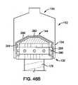
さらなる態様では、圧力ジャケットは、ローリングダイヤフラムのノズルを受け入れるように構成された出口部分で終端する切頭円錐状部分を有することができる。圧力ジャケットの近位端は、使用する前にローリングダイヤフラムおよびプランジャを封止する取外し可能シールを有することができる。圧力ジャケットは、蝶番によって互いに枢支接続された第1部分と第2部分とを有することができる。第1部分および第2部分は、閉鎖状態で係止可能であり得る。圧力ジャケットは、ローリングダイヤフラムの少なくとも一部を囲む取外し可能閉鎖具を有することができる。取外し可能閉鎖具は、圧力ジャケットの遠位端の対応するねじ山と係合するねじ切り端部を有することができる。圧力ジャケットの近位端は、流体注入器に解除可能に接続するように構成された接続インタフェースを有することができる。圧力ジャケットの近位端は、流体注入器に解除可能に接続するように構成された接続インタフェースを有することができる。圧力ジャケットの遠位端は、ローリングダイヤフラムの少なくとも一部を囲む取外し可能閉鎖具を有することができる。圧力ジャケットは、近位端から半径方向外側に突出するシールドを有することができ、シールドは、流体注入器のハウジングの少なくとも一部と係合するように構成されている。圧力ジャケットは、圧力ジャケットの側壁の外側部分に摺動可能に取り付けられる環状フランジを有することができる。環状フランジは、圧力ジャケットを注入器に係止する第1位置と、圧力ジャケットを注入器から係止解除する第2位置との間で摺動可能であり得る。 In a further aspect, the pressure jacket can have a truncated conical portion terminated at an outlet portion configured to receive the nozzle of the rolling diaphragm. The proximal end of the pressure jacket can have a removable seal that seals the rolling diaphragm and plunger prior to use. The pressure jacket can have a first portion and a second portion that are hinged to each other. The first and second parts may be lockable in the closed state. The pressure jacket can have a removable closure that surrounds at least a portion of the rolling diaphragm. The removable closure can have a threaded end that engages the corresponding thread at the distal end of the pressure jacket. The proximal end of the pressure jacket can have a connection interface configured to be detachably connected to the fluid injector. The proximal end of the pressure jacket can have a connection interface configured to be detachably connected to the fluid injector. The distal end of the pressure jacket can have a removable closure that surrounds at least a portion of the rolling diaphragm. The pressure jacket can have a shield that projects radially outward from the proximal end, the shield being configured to engage at least a portion of the fluid injector housing. The pressure jacket can have an annular flange that is slidably attached to the outer portion of the side wall of the pressure jacket. The annular flange may be slidable between a first position for locking the pressure jacket to the injector and a second position for unlocking the pressure jacket from the injector.
いくつかの態様では、圧力ジャケットは、使用済みローリングダイヤフラムが圧力ジャケットから取り除かれた後に、使用済みローリングダイヤフラムとともに再使用可能であり得る。圧力ジャケットは、ローリングダイヤフラムとともに使い捨てであり得る。圧力ジャケットは、圧力ジャケットの遠位端を囲む第1取外し可能キャップと、圧力ジャケットの近位端を囲む第2取外し可能キャップとを有することができる。圧力ジャケットの遠位端は、圧力ジャケットの貫通孔にローリングダイヤフラムを挿入するかまたはそこから取り除くために、圧力ジャケットの近位端に対して半径方向外側に拡張可能であり得る。圧力ジャケットを流体注入器に永久的に接続することができる。圧力ジャケットを流体注入器に解除可能に接続することができる。アダプタを設けることができ、アダプタは、流体注入器と接続する第1端部と、圧力ジャケットの近位端を解除可能に受け入れる第2端部とを有する。圧力ジャケットは、圧力ジャケットの側壁の外面から半径方向外側に突出するフランジを有することができる。フランジは、フランジを通って軸方向に延在する1つまたは複数の開口部を有することができる。圧力ジャケットの内部に可撓性流体容器を設けることができる。可撓性流体容器は、ローリングダイヤフラムを包囲することができる。可撓性流体容器を、圧力ジャケットの内部にローリングダイヤフラムから近位に配置することができる。圧力ジャケットは、ローリングダイヤフラムを加熱する加熱素子を有することができる。 In some embodiments, the pressure jacket may be reusable with the used rolling diaphragm after the used rolling diaphragm has been removed from the pressure jacket. The pressure jacket can be disposable along with the rolling diaphragm. The pressure jacket can have a first removable cap surrounding the distal end of the pressure jacket and a second removable cap surrounding the proximal end of the pressure jacket. The distal end of the pressure jacket may be radially outwardly expandable with respect to the proximal end of the pressure jacket in order to insert or remove the rolling diaphragm into the through hole of the pressure jacket. The pressure jacket can be permanently connected to the fluid injector. The pressure jacket can be detachably connected to the fluid injector. Adapters can be provided, the adapter having a first end connecting to the fluid injector and a second end releasably accepting the proximal end of the pressure jacket. The pressure jacket can have a flange that projects radially outward from the outer surface of the side wall of the pressure jacket. The flange can have one or more openings extending axially through the flange. A flexible fluid container can be provided inside the pressure jacket. The flexible fluid vessel can surround the rolling diaphragm. The flexible fluid vessel can be placed proximal to the rolling diaphragm inside the pressure jacket. The pressure jacket can have a heating element that heats the rolling diaphragm.
別の態様では、ローリングダイヤフラムは、ローリングダイヤフラムの側壁と一体的に形成されたノズルを有することができる。ノズルは、流体流路セットに接続するように構成されたコネクタを有することができる。コネクタは、ルアーコネクタであり得る。ノズルは、ローリングダイヤフラムの内部を封止するように構成された穿孔可能シールを有することができる。ノズルは、ノズルとローリングダイヤフラムの側壁との間の第1シールと、ノズルを流体流路セットに接続するインタフェースにおける第2シールとを有することができる。ノズルは取外し可能キャップを有することができる。流体流路セットを設けることができ、流体流路セットは穴あけ要素およびシールを有する。シールは、ローリングダイヤフラムのノズルの穿孔可能シールの形状に対応するシール表面を有することができる。 In another aspect, the rolling diaphragm can have a nozzle integrally formed with the sidewall of the rolling diaphragm. The nozzle can have a connector configured to connect to a fluid flow path set. The connector can be a luer connector. The nozzle can have a perforable seal configured to seal the interior of the rolling diaphragm. The nozzle can have a first seal between the nozzle and the sidewall of the rolling diaphragm and a second seal at the interface connecting the nozzle to the fluid flow path set. The nozzle can have a removable cap. A fluid flow path set can be provided, which has a drilling element and a seal. The seal can have a seal surface that corresponds to the shape of the perforable seal on the nozzle of the rolling diaphragm.
本明細書に詳細に記載するさまざまな態様のさらなる詳細および利点は、添付の図面とともにさまざまな態様の以下の詳細を検討することで明らかとなるであろう。 Further details and advantages of the various embodiments described in detail herein will become apparent by considering the following details of the various embodiments with the accompanying drawings.
実例は、概して、本開示のシステムおよび方法の好ましくかつ限定しない態様を示す。説明は、装置のさまざまな態様を提示するが、決して本開示を限定するものとして解釈されるべきではない。さらに、本開示の態様の変更、概念および応用は、当業者により、本明細書における実例および説明を包含するがそれに限定されないものとして解釈されるべきである。 The examples generally show preferred and non-limiting aspects of the systems and methods of the present disclosure. The description presents various aspects of the device, but should by no means be construed as limiting the present disclosure. Moreover, modifications, concepts and applications of aspects of the present disclosure should be construed by those skilled in the art as including, but not limited to, the examples and description herein.
以下の説明は、当業者が、本開示を実施するために企図される記載された態様を作成し使用することができるように提供されている。しかしながら、当業者には、さまざまな変更形態、均等物、変形形態および代替物が依然として容易に明らかとなるであろう。あらゆるこうした変更形態、変形形態、均等物および代替物は、本開示の趣旨および範囲内にあるように意図されている。 The following description is provided to allow one of ordinary skill in the art to create and use the described embodiments intended to carry out the present disclosure. However, various modifications, equivalents, variants and alternatives will still be readily apparent to those of skill in the art. All such modifications, variants, equivalents and alternatives are intended to be within the spirit and scope of this disclosure.
以下の説明の目的で、「上」、「下」、「右」、「左」、「垂直」、「水平」、「頂部」、「底部」、「横方向」、「長手方向」という用語およびそれらの派生語は、図面において向けられているように本開示に関連するものとする。シリンジ、圧力ジャケットおよび/またはローリングダイヤフラムに関連して用いる場合の「近位」という用語は、シリンジ、圧力ジャケットおよび/またはローリングダイヤフラムが注入器に接続するように向けられているときに注入器に最も近い、シリンジ、圧力ジャケットおよび/またはローリングダイヤフラムの部分を指す。「遠位」という用語は、シリンジ、圧力ジャケットおよび/またはローリングダイヤフラムが注入器に接続するように向けられているときに注入器から最も遠い、シリンジ、圧力ジャケットおよび/またはローリングダイヤフラムの部分を指す。「半径方向」という用語は、近位端と遠位端との間に延在する、シリンジ、圧力ジャケットおよび/またはローリングダイヤフラムの長手方向軸に対して垂直な断面における方向を指す。「周囲」という用語は、シリンジ、圧力ジャケットおよび/またはローリングダイヤフラム側壁の内面または外面を取り巻く方向を指す。「軸方向」という用語は、近位端と遠位端との間に延在する、シリンジ、圧力ジャケットおよび/またはローリングダイヤフラムの長手方向軸に沿った方向を指す。しかしながら、本開示は、明示的に反対の指定がある場合を除き、代替的な変形形態およびステップ順序を想定し得ることが理解されるべきである。添付図面に示し以下の本明細書に記載する具体的な装置およびプロセスは単に本開示の例示的な実施形態であることも理解されるべきである。このため、本明細書に開示する実施形態に関連する具体的な寸法および他の物理的特性(すなわち、態様、変形、変動)は、限定するものとしてみなされるべきではない。 For the purposes of the following explanation, the terms "top", "bottom", "right", "left", "vertical", "horizontal", "top", "bottom", "lateral", "longitudinal" And their derivatives shall be relevant to this disclosure as directed in the drawings. The term "proximal" when used in connection with a syringe, pressure jacket and / or rolling diaphragm refers to the syringe when the syringe, pressure jacket and / or rolling diaphragm is directed to connect to the injector. Refers to the closest part of the syringe, pressure jacket and / or rolling diaphragm. The term "distal" refers to the portion of the syringe, pressure jacket and / or rolling diaphragm that is farthest from the syringe when the syringe, pressure jacket and / or rolling diaphragm is directed to connect to the injector. .. The term "radial" refers to a direction in a cross section perpendicular to the longitudinal axis of a syringe, pressure jacket and / or rolling diaphragm that extends between the proximal and distal ends. The term "periphery" refers to the direction surrounding the inner or outer surface of the syringe, pressure jacket and / or rolling diaphragm sidewall. The term "axial" refers to the direction along the longitudinal axis of the syringe, pressure jacket and / or rolling diaphragm that extends between the proximal and distal ends. However, it should be understood that the present disclosure may envision alternative variants and step sequences, unless expressly opposed. It should also be understood that the specific devices and processes shown in the accompanying drawings and described herein below are merely exemplary embodiments of the present disclosure. For this reason, the specific dimensions and other physical properties (ie, aspects, variations, variations) associated with the embodiments disclosed herein should not be considered as limiting.
いくつかの図を通して同様の参照文字が同様の部分を示す図面を参照すると、本開示は、概して、ローリングダイヤフラムとして構成されたシリンジに関する。 Referring to a drawing in which similar reference characters indicate similar parts through several figures, the present disclosure relates generally to syringes configured as rolling diaphragms.
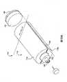
図1を参照すると、流体送達システム100は、自動または電動式流体注入器等の流体注入器102を有することができ、それは、本明細書に記載するように、少なくとも1つのローリングダイヤフラム112および圧力ジャケット110とインタフェースしかつそれらを作動させるように適合され、それらの各々に、造影剤、生理食塩水または任意の所望の医療流体等の医療流体を独立して充填することができる。医療処置中に注入器102を用いて、少なくとも1つのローリングダイヤフラム112のプランジャ144を少なくとも1つのピストンによって駆動することにより、患者の体内に医療流体を注入することができる。注入器102は、マルチローリングダイヤフラム注入器とすることができ、そこでは、2つ以上のローリングダイヤフラム112は、対応する圧力ジャケット110とともに並んだ関係または他の関係で向けられ、注入器102に関連するそれぞれのピストンによって別個に駆動される対応するプランジャ144を含むことができる。2つのローリングダイヤフラム/圧力ジャケットが並んだ関係に配置されかつ2つの異なる医療流体で充填されている実施形態では、ローリングダイヤフラム112の一方または両方から流体を送達するように注入器102を構成することができる。 Referring to FIG. 1, the
プラスチックまたは金属等の好適な構造的材料から形成されたハウジング126内に、注入器102を封入することができる。ハウジング126は、所望の用途に応じてさまざまな形状およびサイズであり得る。たとえば、注入器102は、床の上に配置されるように構成された自立構造であり得るか、または好適な台もしくは支持フレームの上に配置されるようにより小型の設計であり得る。注入器102は、少なくとも1つのローリングダイヤフラム112および圧力ジャケット110をそれぞれのピストン要素に接続する少なくとも1つのポートを含む。 The
少なくとも1つのローリングダイヤフラム112から血管アクセス部位において患者の体内に挿入されるカテーテル、針または他の流体送達接続部(図示せず)に医療流体を送達するために、ローリングダイヤフラム112および圧力ジャケット110を備えた少なくとも1つのシリンジ104の排出ポート142を有するノズルに、少なくとも1つの流体流路セット108を流体接続することができる。少なくとも1つのシリンジ104からの流体流は、流体制御モジュール(図示せず)によって調整することができる。流体制御モジュールは、注入流量、持続時間、総注入量ならびに/または造影剤および生理食塩水の割合等、使用者が選択する注入パラメータに基づいて、生理食塩水および造影剤等の医療流体の患者への送達を調整するように、さまざまなピストン、弁および/または流量調整構造を操作することができる。少なくとも1つのローリングダイヤフラムと、図1を参照して本明細書に記載する流体注入器で、少なくとも1つのローリングダイヤフラムおよび圧力ジャケットを装填し解除可能に保持する少なくとも1つのインタフェースとを含む、本明細書に記載するシステムで使用するように変更することができる好適なフロントローディング流体注入器の1つの実施形態が、全体として参照により本明細書に組み込まれる、Reillyらの米国特許第5,393,858号明細書に開示されている。本システムで使用するように変更することができる関連する多流体送達システムの別の実施形態は、Lazzaroらの米国特許第7,553,294号明細書、Cowanらの同第7,666,169号明細書、(国際公開第2012/155035号パンフレットとして公開された)国際特許出願PCT/米国特許出願公開第2012/037491号明細書およびRileyらの米国特許出願公開第2014/0027009号明細書に記載されており、それらはすべて本出願の譲受人に譲渡され、それらの開示内容は、参照により本明細書に組み込まれる。他の実施形態は、本明細書に開示するローリングダイヤフラムのさまざまな実施形態を含むように設計された新たな流体注入器システムを含むことができる。A rolling
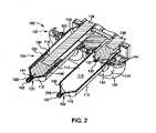
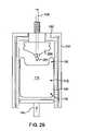
図2は、図1に示す流体注入器102の一部の断面斜視図である。図2を参照すると、シリンジ104は、概して、円筒体または圧力ジャケット110と、圧力ジャケット110とインタフェースするローリングダイヤフラム112とを含む。後述するように、ローリングダイヤフラム112は、流体を受け入れる内部容積114を画定している。ローリングダイヤフラム112は、圧力ジャケット110の少なくとも一部に挿入されているように構成され、圧力ジャケット110は、流体注入器102と係合するように構成されている。シリンジ104は、CT、MRI、PET等の処置で使用されるように適合され、たとえば約200psi~400psiの典型的な動作圧力で動作可能である。いくつかの態様では、ローリングダイヤフラム112は、「Bladder Syringe Fluid Delivery System」という名称の米国特許出願第13/881,072号明細書に記載されているブラダシリンジ、または「Bellows Syringe Fluid Delivery System」という名称の米国特許出願第13/834,624号明細書に記載されているシリンジとすることができ、それらの開示内容は全体として参照により本明細書に組み込まれる。 FIG. 2 is a cross-sectional perspective view of a part of the
圧力ジャケット110の円筒体は、遠位端116および近位端118を有し、貫通孔Tが遠位端116と近位端118との間に延在している、一体型の通常円筒状の本体であり得る。圧力ジャケット110は、通常、再使用可能構成要素であり、ローリングダイヤフラム112は、通常、単回使用構成要素である。別の態様では、ローリングダイヤフラム112は、流体で再充填可能であるように再使用可能であり得る。たとえば、ローリングダイヤフラム112は流体で予め充填することができ、または最初は空とすることができ、1回または複数回にわたり充填および/または再充填することができる。別の態様では、圧力ジャケット110およびローリングダイヤフラム112はともに、各患者に使用した後に廃棄される単回構成要素であり得る。この態様では、圧力ジャケット110およびローリングダイヤフラム112の両方が、使用後に廃棄され、新たな圧力ジャケット110およびローリングダイヤフラム112が流体注入器102に装填される。圧力ジャケット110は、遠位端116と近位端118との間に貫通孔を画定する側壁120を有している。近位端118は、流体注入器102とインタフェースするように適合され、1つまたは複数の取付機構122を含み、それは、流体注入器102に対して圧力ジャケット110を適切に取り付けるように、流体注入器102のハウジング126の前端または面板124において係止機構と係合するように配置されている。例として、圧力ジャケット110を流体注入器102に固定するために液体注入器面板124とインタフェースするように、近位端118に2つの対向するバヨネット取付フランジを設けることができる。いくつかの態様では、圧力ジャケット110は、「Self-Orienting Syringe and Syringe Interface」という名称の米国特許出願第14/526,294号明細書または「Self-Orienting Syringe and Syringe Interface」という名称の米国特許出願第14/526,395号明細書に記載されている接続インタフェースの形態で、圧力ジャケットを流体注入器102に解除可能に固定する接続インタフェースを有することができ、上記出願の開示内容は全体として参照により本明細書に組み込まれる。別の態様では、圧力ジャケット110およびローリングダイヤフラム112を流体注入器102に接続するアダプタを設けることができる。 The cylinder of the
圧力ジャケット110の遠位端116は、出口ポート128で終端する実質的に切頭円錐状の部分を含むことができる。圧力ジャケット110は、限定されないがポリカーボネート、アクリル樹脂またはポリエステル等、医療グレードプラスチック材料、望ましくは透明なプラスチック材料等、任意の好適な医療グレード材料から作製することができる。いくつかの態様では、たとえば、限定されないが、圧力ジャケット110の開口部を通して延在して流体注入器102に装填されたときの圧力ジャケット110の回転を防止する格納式ピンにより、流体注入器102に圧力ジャケット110を解除可能に固定することができる。他の態様では、圧力ジャケット110は、流体注入器102のハウジングと係合して流体注入器102に装填されたときの圧力ジャケット110の回転を防止する、1つまたは複数の脚を有することができる。さらなる態様では、圧力ジャケット110の外周に摺動カラーを設けることができる。摺動カラーは、望ましくは、拡張可能リングと係合して、流体注入器102の対応する係止機構に対してリングを拡張させて圧力ジャケット110を流体注入器102に係止する。 The
図3を参照し、図2を続けて参照すると、ローリングダイヤフラム112は、概して、前方まだは遠位端130、後方または近位端132、およびそれらの間に延在する可撓性側壁134を含む、中空体を含む。近位端132は、閉鎖端壁136を画定している。閉鎖端壁136は、流体注入器102のピストンヘッド138および/またはプランジャ144と直接インタフェースするような形状とすることができる。たとえば、閉鎖端壁136は、同様の形状のピストンヘッド138および/またはプランジャ144と直接インタフェースするように受入れ端ポケットを画定することができる。特に、ピストンヘッド138および/またはプランジャ144は、閉鎖端壁136の形状に一致するような形状とすることができ、またはピストンヘッド138および/またはプランジャ144からの圧力が、ピストンヘッド138および/またはプランジャ144の形状と実質的に一致するように端壁136を適合させることができる。閉鎖端壁136は、別法として、ピストンヘッド138またはプランジャ144と同様に係合する、取り付けられた剛性基部要素を含むことができる。一態様では、ローリングダイヤフラム112の近位端132および/または遠位端130は、側壁134に対してより剛性を有することができる。さらに別の態様では、単一の一体構造に合わせてともに形成される複数の個々の層から、ローリングダイヤフラム112を形成することができる。側壁134が注入処置中に転動する際に、側壁134から層のうちの少なくとも1つが剥離する可能性がある。層のうちの少なくとも1つを、所定温度で収縮するように活性化される熱収縮材料から作製することができる。たとえば、オートクレーブプロセス中に、所定温度を達成することができる。この態様では、熱収縮層は圧力ジャケットとしての役割を果たすことができる。側壁134は、平滑な、実質的に均一の構造を有することができ、または注入処置中に転動を容易にするように、側壁134に1つまたは複数のリブを設けることができる。側壁134に、1つまたは複数のしるし(図示せず)を形成することができる。別の態様では、側壁134は、側壁134の転動を促進するように、その長手方向長さに沿って不均一な厚さを有することができる。たとえば、側壁134の近位端132から遠位端130に向かう転動を容易にするために、遠位端130またはその近くの側壁134より近位端132またはその近くの側壁134を薄くすることができる。遠位端130またはその近くの厚い方の側壁134は、圧力ジャケット110として機能することができ、転動しない可能性がある。具体的な実施形態では、遠位端130またはその近くの側壁134は、実質的に剛性であり得る。 With reference to FIG. 3 and continuing with reference to FIG. 2, the rolling
側壁134の後方または近位部分は、閉鎖端壁136に接続し、側壁134の前方または遠位部分は、閉鎖端壁136とは反対側の排出首部140を画定している。閉鎖端壁136は、たとえばローリングダイヤフラム112の中心長手方向軸から延在する半径方向に、不均一な厚さを有することができる。いくつかの実施形態では、端壁136は、中心近くで厚くなり、側壁134の接続部の近くで薄くなることができる。排出首部140は、圧力ジャケット110の出口ポート128と位置合わせされるように、圧力ジャケット110の遠位端116の内側部分に受け入れられるように適合されている。ローリングダイヤフラム112の遠位端130は、圧力ジャケット110の内部に永久的に固定し、接着剤で固定し、または摩擦嵌合接続もしくは圧力ジャケット110の遠位端で固定することによる等、他の好適な機械的接続による等、取外し可能に固定することができる。排出首部140は、排出ポート142で終端し、排出ポート142は、1つの限定しない態様によれば、穿孔可能な箔またはエラストマーシール等、滅菌の目的で破砕可能シール(本明細書で考察する)を有することができる。 The posterior or proximal portion of the
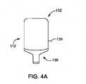
ローリングダイヤフラム112の側壁134は、ピストンヘッド138および/またはプランジャ144の作用によりそれ自体の上を転がるように構成されている、軟質な、曲げやすい、または可撓性のある、ただし自立する本体を画定する。特に、図2に示すように、ローリングダイヤフラム112の側壁134は、ピストンおよび/またはプランジャ144が遠位方向に移動する際に、その外面が半径方向内側方向に折り畳まれ反転するように転動し、ピストンおよび/またはプランジャ144が近位方向に後退される際に、半径方向外側方向に、反対に展開し広がるように構成されている。図3を参照すると、閉鎖端壁136は、側壁134の反転または転動の開始を容易にするように凹形状を有することができる。別の態様では、ローリングダイヤフラム112の側壁134は、複数の軸方向折目112aで折り畳むことにより、図4Aに示すような第1の非圧縮状態から図4Bに示すような第2の圧縮状態まで、ピストンヘッド138の作用によって押しつぶされるように構成することができる。軸方向折目112aのうちの1つまたは複数は、ローリングダイヤフラム112の側壁134の所定の軸方向位置に予め形成することができる。The
ローリングダイヤフラム112は、任意の好適なプラスチック材料、望ましくは、限定されないが、ポリプロピレンランダムコポリマー、ポリプロピレンインパクトコポリマー、ポリプロピレンホモポリマー、ポリプロピレン、ポリエチレンテレフタレート、POM、ABS、HPDE、ナイロン、環状オレフィンコポリマー、多層ポリプロピレン、ポリカーボネート、エチレン酢酸ビニル、ポリエチレン等、透明なプラスチック材料から作製することができる。ローリングダイヤフラム112の材料は、望ましくは、必要な引張応力および平面応力要件、水蒸気透過および化学的/生物学的適合性を満たすように選択される。いくつかの態様では、ローリングダイヤフラム112は、電圧の印加に応答して拡張または収縮する少なくとも1つの電気活性ポリマー層を有することができる。電気活性ポリマー層は、プランジャ144を解除するかまたはプランジャ144と係合するようにローリングダイヤフラム112の側壁134を拡張または収縮させるように活性化することができる。いくつかの態様では、電気活性ポリマー層は、NAFIONTM材料またはFLEMIONTM材料から作製することができる。さまざまな実施形態では、エチレンオキシドへの暴露または電磁放射滅菌処置等、滅菌処置を耐えることができる。The rolling
本明細書におけるさまざまな実施形態によるローリングダイヤフラム112は、関連する努力傾注分野においてブロー成形シール(blow-mold-seal)(BFS)技法とも呼ばれるブロー成形-充填-キャッピング(blowing-filling-capping)(BFC)によって作製することができ、そこでは、後述するように、ローリングダイヤフラム112は、ブロー成形され、生理食塩水または造影剤等の所望の医療流体で充填され、一体的に形成され/成形された破断可能シールで排出ポート142を封止することにより、無菌で封止される。BFC技法により、通常1つの機械または装置でローリングダイヤフラム112を形成し、充填し、封止することができる。これらのステップは、滅菌が維持された条件下で、形成され、充填され、封止されたローリングダイヤフラム112に汚染物質を導入する可能性を制限して、達成することができる。アセンブリ全体を、滅菌するためにオートクレーブで処理するか、または他の方法で処理することができる。破断可能シールは、ローリングダイヤフラム112の充填の最後に、成形プロセスの一部として形成される。滅菌が強化された予め形成され予め充填されたローリングダイヤフラム112は、BFCプロセスから得られる。破断可能シールは、使用者によって外部に除去されるかまたは穴があけられるように設計することができ、またはピストンヘッド138がローリングダイヤフラム112において遠位にまたは前方に移動する際に、ローリングダイヤフラム112内で予め設定された内部圧力に達すると、容易に破裂するように設計することができる。別の態様では、圧力ジャケット110に設けられた穿孔要素によって、ローリングダイヤフラム112を破断させることができる。別の態様では、剛性を向上させ汚染を防止するように、保護カバー(図示せず)にローリングダイヤフラム112を入れることができる。保護カバーは、注入器102に設置する前に、ローリングダイヤフラム112から取り除く場合もあれば取り除かない場合もある。種々の形状を有するようにローリングダイヤフラム112を形成することができる。たとえば、ローリングダイヤフラム112は、円筒状、円錐形、球形、楕円形、卵形等であり得る。さらに、ローリングダイヤフラムは、異なる幅対長さ比を有することができる。たとえば、ローリングダイヤフラム112を、直径がその長手方向の長さに比較して実質的に小さいかまたは大きいように形成することができる。当業者は、ローリングダイヤフラム112から実質的に一定かつ予測可能な流量の流体を送達するために、注入器102を望ましくは、プランジャ144の移動を制御するようにプログラムし得ることを理解するであろう。 The rolling
ローリングダイヤフラム112の外径は、ローリングダイヤフラム112が、圧力ジャケット110の貫通孔および内面によって画定された内部空間内に適合するような寸法とすることができる。一態様では、ローリングダイヤフラム112は、ローリングダイヤフラム112の外面が圧力ジャケット110の壁の内面に当接するように、圧力ジャケット110内に密にはまる。別の態様では、ローリングダイヤフラム112の外面の少なくとも一部と圧力ジャケット110の内面との間に間隙があるように、ローリングダイヤフラム112は、圧力ジャケット110内に緩くはまる。注入処置中、ローリングダイヤフラム112の外面が圧力ジャケット110の内面に当接するように、ローリングダイヤフラム112を圧力下で拡張させることができる。 The outer diameter of the rolling
図5Aおよび図5Bは、本開示の別の態様によるローリングダイヤフラム112を示す。図5Bは、線A-Aに沿った図5Aに示す側断面図ローリングダイヤフラムである。図5Aおよび図5Bに示すローリングダイヤフラム112の構成要素は、図2および図3を参照して本明細書に記載したローリングダイヤフラム112の構成要素と実質的に同様である。図5Aおよび図5Bにおける参照数字を用いて、図2および図3における対応する参照数字として同一の構成要素が示される。図2および図3に概して示すローリングダイヤフラム112に関する先の考察は、図5Aおよび図5Bに示す態様に適用可能であるため、これらのシステムの間の関連する相違のみについて、以下考察する。 5A and 5B show the rolling
最初に図5Aを参照すると、ローリングダイヤフラム112の遠位端130は、端部が開放した排出首部140を有し、それは、流体流路セット(図示せず)に接続することができる対応する接続インタフェースに接続するための接続インタフェース140aを有している。いくつかの態様では、接続インタフェース140aは、流体流路セットへの接続インタフェースの対応するねじ山と嵌合する1つまたは複数のねじ山140bを有するねじ切りインタフェースである。いくつかの態様では、流体流路への接続インタフェースは、ルアー接続部等、流体流路に接続するように構成された接続部を有することができる。 First referring to FIG. 5A, the
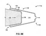
図5Bを参照すると、排出首部140は、側壁134の厚さT2より大きい第1側壁厚さT1を有している。厚さT1は、排出首部140が、排出首部140を実質的に変形させることなく、流体流路セット(図示せず)の対応する接続インタフェースに接続するのを可能にするように十分剛性であり得るように選択される。厚さT2は、ローリングダイヤフラム112の側壁134が、本明細書に記載するように側壁134の転動および展開を可能にするように可撓性があるように選択される。閉鎖端壁136等、ローリングダイヤフラム112の近位端132は、側壁134の転動中に変形を防止するように補強することができる。いくつかの態様では、ローリングダイヤフラム112の近位端132は、プランジャ144(図示せず)と係合するように構成されている。近位端132は、ローリングダイヤフラム112の側壁134の転動、およびいくつかの実施形態では展開を開始するように可撓性側壁を有する丸みがつけられた折縁226を有している。この実施形態では、折縁226は、端壁136の遠位部分274まで連続的に増大する側壁厚さT3を有する遠位に延在する傾斜面272に遷移することができる。遠位部分274は、遠位部分274の上面から遠位に延在する丸みが付けられた中心部分276と、遠位部分274の下面から近位に延在するプランジャ係合部分244とを有することができる。プランジャ係合部分244は、本明細書に記載するように、プランジャ144(図示せず)と係合するように構成されている。ローリングダイヤフラム112の近位端132は、傾斜面272の下面に沿ってプランジャ係合部分244から半径方向外側に突出する1つまたは複数のリブ278を有することができる。Referring to FIG. 5B, the
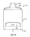
図6は、本開示の別の態様によるローリングダイヤフラム112の側断面図である。ローリングダイヤフラム112の第1部分112aは、第1径D1を有し、ローリングダイヤフラム112の第2部分112bは、第1径D1とは異なる第2径D2を有している。いくつかの態様では、第1部分112aは、ローリングダイヤフラム112の遠位端130からおよその中間点まで延在する、ローリングダイヤフラム112の前方部分とすることができ、第2部分112bは、ローリングダイヤフラム112のおよその中間点から近位端132まで延在する、ローリングダイヤフラム112の後方部分とすることができる。第2部分112bが折縁226を中心に反転する際に第2部分112bが第1部分112aの内部で入れ子になることができるように、第1径D1を第2径D2より大きくすることができる。第1部分112a内に第2部分112bを入れ子にすることにより、折縁226における円周圧縮が最小限になる。折縁226は、ローリングダイヤフラム112の第1部分112aおよび第2部分112bの側壁134に比較して厚くなった側壁134aを有することができる。いくつかの態様では、第1部分112aは、側壁134を包囲するかまたは側壁134によって包囲されるカラー228を有することができ、第2部分112bは、プランジャ144(図示せず)との係合を補強するプランジャ支持基部230を有することができる。図40は、図6に示す可変直径を有する側壁134なしに、プランジャ支持基部230およびカラー228を備えたローリングダイヤフラム112を示す。FIG. 6 is a side sectional view of the rolling
図7は、本開示の別の態様によるローリングダイヤフラム112の側断面図である。ローリングダイヤフラム112の第1部分112aは第1側壁134aを有し、ローリングダイヤフラム112の第2部分112bは、第1側壁134aとは厚さが異なる第2側壁134bを有している。ローリング径112の内径は、第1部分134aと第2部分134bとの間で一定であり得る。いくつかの態様では、第1部分112aは、ローリングダイヤフラム112の遠位端130からおよその中間点まで延在する、ローリングダイヤフラム112の前方部分とすることができ、第2部分112bは、ローリングダイヤフラム112のおよその中間点から近位端132まで延在する、ローリングダイヤフラム112の後方部分とすることができる。ローリングダイヤフラム112の第1部分112aがローリングダイヤフラム112の第2部分112bより剛性があるように、第1側壁134aを第2側壁134bより厚くすることができる。第2部分112bは、折縁226を中心に反転する際に、第1部分112aの内部で入れ子になる。第2側壁134bの外部部分は、カラー228によって周方向に支持することができる。いくつかの態様では、第1部分134aおよび第2部分134bは実質的に同一の壁厚さを有することができ、第1部分134aと第2部分134bとの間のおよその中間点は、第1部分134aおよび第2部分134bの側壁に対して側壁厚さの薄い部分を有し、それにより、折縁または反転正面を画定し、第2部分134bがそれ自体の上で反転する際に、側壁の座屈を防止する。 FIG. 7 is a side sectional view of the rolling
図8Aは、本開示の別の態様によるローリングダイヤフラム112およびプランジャ144の側断面図であり、そこでは、プランジャ144は第1位置で示されている。図8Bは、図8Aに示すローリングダイヤフラム112およびプランジャ144の側断面図であり、そこでは、プランジャ144は第2位置で示されている。いくつかの態様では、ローリングダイヤフラム112の側壁134はテーパ状であり、それにより、幅が狭くなり、直径が近位端132から遠位端130に向かって低減してプランジャ144のテーパ形状に実質的に対応する。プランジャ144がその最大遠位位置に前進した後に残留容積を最小限にするために、側壁134の折畳み部分170と非折畳み部分172との間に接触があるように、側壁134を折り畳むことができる。側壁134が転動する半径Rは、折畳み部分における局所応力を低減させるように望ましくは最小化される。図8Bを参照すると、別の態様では、プランジャ144がその最大遠位位置まで前進される際に、側壁134の折畳み部分170と非折畳み部分172との間に接触がないように、側壁134を折り畳むことができる。この態様では、半径R’は、図8Aの半径Rより大きい。 FIG. 8A is a side sectional view of the rolling
図9Aは、本開示の別の態様によるローリングダイヤフラム112の部分側断面図であり、そこでは、ローリングダイヤフラム112は第1状態で示されている。図9Bは、図9Aに示すローリングダイヤフラム112の部分側断面図であり、ローリングダイヤフラム112は、プランジャ144と係合した後に第2の状態で示されている。ローリングダイヤフラム112の近位端132を最初は凸形状に形成することができ、それにより、近位端132の一部が近位方向に外側に凸状に延在する。プランジャ144が、図9Bに示すように近位端132と係合すると、プランジャ144が遠位方向に前進される際に、近位端132の凸形状は遠位端146に向かって反転し、それにより近位端132は実質的に凹状である。近位端132は、プランジャ144が係合するとローリングダイヤフラム112の転動を容易にする、予め形成された転動半径Rを有することができる。いくつかの態様では、近位端132は、プランジャ144と係合すると近位端132の初期凸形状から凹形状への反転を容易にする、1つまたは複数の予め画定された折部分132aを有することができる。折部分132aは、ローリングダイヤフラム112の側壁134の厚さに対して薄い側壁を有することができる。 FIG. 9A is a partial side sectional view of the rolling
図10Aは、本開示の別の態様によるローリングダイヤフラム112の側面図である。ローリングダイヤフラム112は、半径方向内側方向に延在するように形成された1つまたは複数の窪み要素を有している。いくつかの態様では、側壁134が、1つまたは複数の窪み要素182aが形成されている領域の少なくとも一部にわたって実質的に均一な厚さを有するように、1つまたは複数の窪み要素182aを形成することができる。他の態様では、側壁134が、1つまたは複数の窪み要素182aが形成されている場所において相対的に薄いかまたは厚い側壁厚さを有するように、1つまたは複数の窪み要素182aを形成することができる。側壁134の転動を容易にするために、1つまたは複数の窪み要素182aを、ローリングダイヤフラム112の外周に一様にまたは非一様に間隔を空けて配置することができる。プランジャ144(図示せず)が遠位方向に前進される際に、複数の窪み要素182aのうちの1つまたは複数と係合するように、プランジャ144を構成することができる。いくつかの態様では、プランジャ144は、1つまたは複数の窪み要素182aを有するローリングダイヤフラム112の形状に対応するような形状とすることができる。 FIG. 10A is a side view of the rolling
図10Bは、本開示の別の態様によるローリングダイヤフラムの部分側面図である。ローリングダイヤフラム112は、半径方向外側方向に延在するように形成された1つまたは複数のリブ182bを有している。いくつかの態様では、側壁134が、1つまたは複数のリブ182bが形成されている領域の少なくとも一部にわたって実質的に均一な厚さを有するように、1つまたは複数のリブ182bを形成することができる。他の態様では、側壁134が、1つまたは複数のリブ182bが形成されている位置において相対的に薄いかまたは厚い側壁厚さを有するように、1つまたは複数のリブを形成することができる。1つまたは複数のリブ182bは、1つまたは複数のリブ182bの第1部分がリブ182の第2部分に比較してさらに半径方向外側に延在するような形状とすることができる。たとえば、リブ182bが、1つまたは複数のリブ182bの中心部分に比較して近位端および遠位端においてまたはその近くでさらに半径方向外側に延在するように、1つまたは複数のリブ182bを形成することができる。側壁134の転動を容易にするために、1つまたは複数のリブ182bを、ローリングダイヤフラム112の外周に一様にまたは非一様に間隔を空けて配置することができる。プランジャ144(図示せず)が遠位方向に前進される際に複数のリブ182bのうちの1つまたは複数と係合するように、プランジャ144を構成することができる。いくつかの態様では、プランジャ144は、1つまたは複数のリブ182を有するローリングダイヤフラム112の形状に対応するような形状とすることができる。 FIG. 10B is a partial side view of a rolling diaphragm according to another aspect of the present disclosure. The rolling
図11Aは、本開示の別の態様によるローリングダイヤフラム112およびプランジャ144の側断面図であり、プランジャ144は第1状態で示されている。図11Bは、図11Aに示すローリングダイヤフラム112およびプランジャ144の側断面図であり、プランジャ144は第2状態で示されている。近位端壁136が遠位端130に向かって内側に反転して、ローリングダイヤフラム112の内部容積114に流体がないように、ローリングダイヤフラム112を最初に形成することができる。ローリングダイヤフラム112の近位端壁136を近位方向に引き出し、ローリングダイヤフラム112の内部容積を流体で充填するために、プランジャ144は、近位端壁136の少なくとも一部と係合して、近位方向に引き出す前に近位端壁136を「つかむ」。いくつかの態様では、プランジャ144の外径は、図11Aに示す反転状態のローリングダイヤフラム112の内径よりわずかに小さくすることができる。ローリングダイヤフラム112の近位端壁136のプランジャ144との接続を容易にするために、膨張可能発泡体等の拡張可能材料214を設けることができる。拡張可能材料214は、プランジャ144がローリングダイヤフラム112の近位端壁136と係合する前に非拡張状態にあり得る。たとえば、プランジャ144がローリングダイヤフラム112の近位端壁136に向かって前進される際に、プランジャ144によって穿孔される容器に、拡張可能材料214を収容することができる。拡張可能材料214は、空気に露出すると拡張可能となることができ、それにより、拡張して、近位端壁136およびプランジャ144においてローリングダイヤフラム112の側壁134と係合する。拡張可能材料214は、所定時間の後に硬化して、プランジャ144をローリングダイヤフラム112の近位端壁136に永久的にまたは解除可能に接続し、プランジャ144の移動によりローリングダイヤフラム112が近位方向に引き出されるのを可能にすることができる。拡張可能材料214に対する表面と近位端壁136および/または近位端壁136に近接する内側に面する外壁との間に係合を提供するために、側壁134の折畳み部分にかつ/またはプランジャ144の遠位部分の外周の少なくとも一部に、1つまたは複数の把持要素246を設けることができる。 FIG. 11A is a side sectional view of the rolling
図12Aは、本開示の別の態様によるローリングダイヤフラム112およびプランジャ144の側断面図であり、プランジャ144は第1状態で示されている。図12Bは、図12Aに示すローリングダイヤフラム112およびプランジャ144の側断面図であり、プランジャ144は第2状態で示されている。近位端壁136が遠位端130に向かって内側に反転され、それにより、ローリングダイヤフラム112の内部容積に流体がなくなるように、ローリングダイヤフラム112を最初に形成することができる。ローリングダイヤフラム112の近位端壁136を近位方向に引き出し、ローリングダイヤフラム112の内部容積を流体で充填するために、プランジャ144は、近位端壁136の少なくとも一部と係合して、近位方向に引き出す前に近位端壁136を「つかむ」。いくつかの態様では、プランジャ144の外径は、図12Aに示す反転状態のローリングダイヤフラム112の内径よりわずかに小さくすることができる。ローリングダイヤフラム112の近位端壁136のプランジャ144との接続を容易にするために、プランジャ144の遠位部分は拡張可能バルーン216を有することができる。バルーン216の内部に流体または加圧ガス等の作動流体を導入することにより、バルーン216を、図12Aに示すような収縮状態から図12Bに示すような膨張状態に拡張させることができる。収縮状態から膨張状態にバルーン216が拡張することにより、バルーン216は、近位端壁136においてローリングダイヤフラム112の側壁134と係合する。したがって、プランジャ144によって付勢されると、ローリングダイヤフラム112を近位方向に引き出すことができる。 FIG. 12A is a side sectional view of the rolling
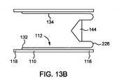
図13Aは、本開示の別の態様によるローリングダイヤフラム112の側断面図である。図13Bは、図13Aに示すローリングダイヤフラム112の側断面図であり、そこでは、プランジャ144がローリングダイヤフラム112と係合している。いくつかの態様では、ローリングダイヤフラム112の近位端132を、圧力ジャケット110の近位端118ではなく遠位端116に接続することができ、それにより、ローリングダイヤフラム112は、図2に示すローリングダイヤフラム112に対して反転する。特に、ローリングダイヤフラム112の側壁134は、最初は、ローリングダイヤフラム112の遠位端130が圧力ジャケット110の近位端118に向かって配置されるように、圧力ジャケット110の内部に反転する。プランジャ144は、ローリングダイヤフラム112の遠位端130に設けられている。図13Bを参照すると、ローリングダイヤフラム112をプランジャ144と同時成形することができる。同時成形した後、ローリングダイヤフラム112をブロー成形技法によってその最終形態まで拡張させることができる。たとえば、ストレッチブロー成形技法によってローリングダイヤフラム112を拡張させることができる。別法として、ローリングダイヤフラム112をその最終的な拡張形状に成形することができ、ローリングダイヤフラム112とともにプランジャ144を同時成形することができる。 FIG. 13A is a side sectional view of the rolling
図14Aは、本開示の別の態様によるローリングダイヤフラム112およびプランジャ144の側断面図である。ローリングダイヤフラム112は実質的に球形の形状を有している。ローリングダイヤフラム112の近位端132は、プランジャ144に形成された対応する係合部材218bと係合する係合部材218aを有することができる。近位端132は、プランジャ144と係合すると、第1の凸状形態から第2の凹状形態に反転する。ローリングダイヤフラム112の遠位端130は、遠位方向においてプランジャ144のストロークの最後にプランジャ144と係合する支持要素220を有することができる。支持要素220は、ローリングダイヤフラム112の内部容積内に設けることができる。別法として、支持要素220は、ローリングダイヤフラム112の遠位端130において外部側壁と係合することができる。プランジャ144は、望ましくは、ローリングダイヤフラム112の内部容積から実質的にすべての流体を排出するような形状である。 FIG. 14A is a side sectional view of the rolling
図14Bは、本開示の別の態様によるローリングダイヤフラムの側断面図である。図14Aに示すローリングダイヤフラム112の実質的に球形の形状と同様に、図14Bのローリングダイヤフラム112は、実質的に楕円形の形状を有している。ローリングダイヤフラム112は、ローリングダイヤフラム112の長手方向に沿って延在する長軸A1と、長手方向に対して垂直に延在する短軸A2とを有する楕円形断面を有し、長軸A1は短軸A2より長い。このように、ローリングダイヤフラム112は、ローリングダイヤフラム112のおよその長手方向中間点から遠位端130まで延在する第1部分と、第1部分に対して形状が相補的でありかつ第1部分から近位端132まで延在する第2部分とを有している。流体注入器102(図1に示す)は、ローリングダイヤフラム112の形状に関わらず一定の流体流を提供するアルゴリズムを内蔵したコントローラを有することができる。たとえば、コントローラは、さまざまな長手方向箇所においてピストンの速度を増減させて、こうした長手方向箇所におけるローリングダイヤフラム112の断面積の変化によるあらゆる流体流量変化を補償するように、ピストン(図2に示す)の速度を制御することができる。FIG. 14B is a side sectional view of the rolling diaphragm according to another aspect of the present disclosure. Similar to the substantially spherical shape of the rolling
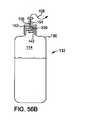
図15Aは、本開示の別の態様による、ローリングダイヤフラム112とローリングダイヤフラム112の少なくとも一部を包囲する環状スリーブ222との側面斜視図である。環状スリーブ222は、環状スリーブ222の側壁を通って延在する1つまたは複数の開口部224を有することができる。いくつかの態様では、圧力ジャケット110は、ローリングダイヤフラム112を圧力ジャケット110の内部側壁120または環状スリーブ222に対して引っ張る真空手段を有することができる。さらに別の態様では、圧力ジャケット110は、環状スリーブ222の1つまたは複数の開口部224を通して加圧空気を導入することによって、使用後に圧力ジャケット110からローリングダイヤフラム112を解除する圧力手段を有することができる。ローリングダイヤフラム112の外面が環状スリーブ222の内面に固着しないように、かつ使用後に環状スリーブ222からのローリングダイヤフラム112の除去を容易にするように、環状スリーブ222の内部側壁を凹凸にすることができる。 FIG. 15A is a side perspective view of the rolling
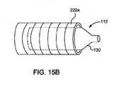
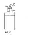
図15Bを参照すると、ローリングダイヤフラム112は、ローリングダイヤフラム112の少なくとも一部を包囲する環状シュリンクラップスリーブ222aを有している。シュリンクラップスリーブ222aは、半径方向内側に収縮してローリングダイヤフラム112の外側側壁134に対して圧縮するように、熱活性化することができる。シュリンクラップスリーブ222aは、圧力ジャケット110(図示せず)とローリングダイヤフラム112との間に配置することができる。 Referring to FIG. 15B, the rolling
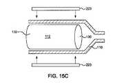
図15Cを参照すると、ローリングダイヤフラム112の少なくとも一部の周囲に加熱素子223を設けることができる。圧力ジャケット110の内部側壁または外部側壁等、圧力ジャケット110に加熱素子223を配置することができる。いくつかの態様では、ローリングダイヤフラム112の側壁134を予熱して、たとえば、プランジャ144(図示せず)が作用するときにローリングダイヤフラム112の柔軟性を上昇させかつその反転を促進するように、加熱素子223を構成することができる。加熱素子は、図15Bに示すシュリンク-ラップスリーブに熱を施すことができる。 Referring to FIG. 15C, the
図16Aは、本開示の別の態様によるローリングダイヤフラム112およびプランジャ144の側断面図である。この態様によれば、ローリングダイヤフラム112は、最初に折畳みまたは空状態にある。ローリングダイヤフラム112の少なくとも一部とプランジャ144との間に、接着剤層232が配置されている。ローリングダイヤフラム112の少なくとも一部およびプランジャ144の少なくとも一部に、接着剤層232を付着させることができる。接着剤層232は、プランジャ144が近位方向に移動すると、ローリングダイヤフラム112およびプランジャ144の一方または両方から解除可能であり得る。いくつかの態様では、側壁134がそれ自体の上で転動する前に、ローリングダイヤフラム112の側壁134の外側部分に接着剤層232を設けることができる。接着剤層232は、側壁134の反転部分にプランジャ144が係合したときに側壁134の座屈を防止するのに役立つことができる。ローリングダイヤフラム112の内部容積114は、最初は空であり得る。ローリングダイヤフラム112の近位端132を遠位端130から引き出し内部容積114に流体を充填するために、プランジャ144は、ローリングダイヤフラム112の反転部分の端壁および/または側壁134と係合する。接着剤層232は、プランジャ144が近位方向に後退される際にローリングダイヤフラム112の側壁134の反転部分に接着力を加える感圧接着剤であり得る。接着剤層232は、折縁226において側壁134から剥離することができ、またはローリングダイヤフラム112の側壁134に付着し続けることができる。接着剤層232は接着剤コーティングであり得る。プランジャ144は、プランジャ144の相互移動を可能にするように注入器のピストンと解除可能に係合するように構成された1つまたは複数のピストン係合要素234を有することができる。いくつかの態様では、ローリングダイヤフラム112の内部容積114は、プランジャ144(図示せず)が近位方向に後退されるときにローリングダイヤフラム112内に流体を引き込むのに役立つ真空を有することができる。図16Bにおいて、接着剤コーティング等の接着剤層232は、ローリングダイヤフラム112の側壁134と圧力ジャケット110との間に配置されている。いくつかの態様では、プランジャ(図示せず)がローリングダイヤフラム112の近位端132を遠位端130に向かって付勢する際に、ローリングダイヤフラム112は圧力ジャケット110の内部側壁から剥離する。ローリングダイヤフラム112と圧力ジャケット110との間の接着接触面に剥離層(図示せず)を設けることができる。 FIG. 16A is a side sectional view of the rolling
図17Aは、本開示の別の態様によるローリングダイヤフラム112の側面斜視図である。図17Bは、図17Aに示すローリングダイヤフラム112の上面図である。ローリングダイヤフラム112は、側壁134の外周に複数の折畳み可能タブ236を有している。各折畳み可能タブ236の第1端を側壁134の外側部分に接続することができ、一方で、第2端は、側壁134の外側部分の円周方向において第1端に対して折畳可能である。折畳み可能タブ236のすべてが側壁134の外側部分に対して折り畳まれる場合等、折畳み形態では、ローリングダイヤフラム112の中身を識別するラベル等のしるし238を識別することができるように、折畳み可能タブ236を位置合せすることができる。 FIG. 17A is a side perspective view of the rolling
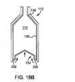
図18は、本開示の別の態様によるローリングダイヤフラムの側面図である。ローリングダイヤフラム112の側壁134は、ローリングダイヤフラム112の内部容積114に流体が充填されているか否かを示す1つまたは複数の流体存在指標240を有することができる。1つまたは複数の流体存在指標240は、ローリングダイヤフラム112の側壁134に一体的に形成することができる。 FIG. 18 is a side view of the rolling diaphragm according to another aspect of the present disclosure. The
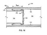
図19は、本開示の別の態様によるローリングダイヤフラム112およびプランジャ144の側断面図である。プランジャ144は、プランジャ144の遠位端から半径方向外側に延在するスカート174を有している。スカート174は、プランジャ144が遠位方向に前進される際に内部容積114内で遠位方向に流体を前進させるように、ローリングダイヤフラム112の側壁134に対して圧縮される。スカート174は、折目176における流体の残留体積を最小限にするかまたはなくす。 FIG. 19 is a side sectional view of the rolling
図20Aは、本開示の別の態様によるローリングダイヤフラム112およびプランジャ144の断面図である。プランジャ144は、その遠位端にピストン178を有し、それにより、ピストン178は、プランジャ144の遠位端に形成された流体またはエラストマー充填空洞180内で往復移動可能である。ローリングダイヤフラム112の内部容積114からの流体送達中等、プランジャ144が遠位方向に前進される際に、ピストン178は空洞180内に押し込まれ、それにより空洞180内の流体またはエラストマーの圧力が上昇する。流体またはエラストマーの圧力の上昇により空洞180がローリングダイヤフラム112の側壁134に対して拡張するように、空洞180は望ましくは可撓性がある。空洞180は、プランジャ144が遠位方向に前進される際に、流体を内部容積114内で前進させるように、ローリングダイヤフラム112の側壁134に対して圧縮される。空洞180の拡張により、折目176における流体の残留体積が最小限になるかまたはなくなる。プランジャ144が近位方向に後退されると、ピストン178もまた空洞180から後退して、その中の圧力を低下させ、プランジャ144をローリングダイヤフラム112から後退させることができる。いくつかの態様では、空洞180をエラストマーで充填することができる。 FIG. 20A is a cross-sectional view of the rolling
図20Bは、本開示の別の態様によるローリングダイヤフラム112およびプランジャ144の側断面図である。図20Aに示すローリングダイヤフラム112と同様に、プランジャ144はその遠位端にピストン178を有し、それにより、ピストン178は、プランジャ144の遠位端に形成された流体充填空洞180内で往復移動可能である。いくつかの態様では、空洞180をエラストマーで充填することができる。ローリングダイヤフラム112の充填中等、プランジャ144が、最初に圧縮または空形態で、近位方向に引き出される際に、プランジャ144に対して近位方向にピストン178を独立して移動させることができ、それにより、空洞180内の流体の圧力が上昇する。流体圧力の上昇により空洞180がローリングダイヤフラム112の側壁134に対して拡張するように、空洞180は望ましくは可撓性がある。プランジャ144が近位方向に引き出される際に、側壁134と接触して、プランジャ144と側壁134との間の把持力を増大させるように、空洞180は、ローリングダイヤフラム112の側壁134に対して圧縮される。 FIG. 20B is a side sectional view of the rolling
図20Cは、本開示の別の態様によるローリングダイヤフラム112およびプランジャ144の側断面図である。図20Aに示すローリングダイヤフラム112と同様に、プランジャ144はその遠位端にピストン178を有し、それにより、ピストン178は、プランジャ144の遠位端に形成された流体充填空洞180内で往復移動可能である。いくつかの態様では、空洞180をエラストマーで充填することができる。空洞180は、第1遠位部分180aと、流体ライン180cを介して第1遠位部分180aと流体連通している第2近位部分180bとを有している。プランジャ144が、ローリングダイヤフラム112の流体による充填中等、近位方向に引き出されている際に、プランジャ144に対して近位方向にピストン178を独立して移動させることができ、それにより、流体ライン180cを通して流体を第2近位部分180bから第1遠位部分180a内に押し込んで、空洞180内の流体の圧力を上昇させる。第1遠位空洞180a内の圧力を上昇させる際のピストン178の機械的流体利点を増大させるように、ピストン178の外径を、第2の第1遠位部分180の外径より小さくすることができる。流体圧力の上昇により第1遠位部分180aがローリングダイヤフラム112の側壁134に対して拡張するように、空洞180は望ましくは可撓性がある。第1遠位部分180aは、プランジャ144が近位方向に引き出される際に、側壁134と接触して側壁134に対する把持力を増大させるように、ローリングダイヤフラム112の側壁134に対して圧縮される。 FIG. 20C is a side sectional view of the rolling
図21Aは、本開示の別の態様によるローリングダイヤフラム112およびプランジャ144の側断面図である。ローリングダイヤフラム112は組込みプランジャ144を有している。いくつかの態様では、プランジャ144は、ローリングダイヤフラム112の内部容積114内に配置される。別法として、ローリングダイヤフラム112の近位端132において、成形によりまたは接着剤による等、プランジャ144を形成することができる。使用する前、ローリングダイヤフラム112の近位端132は、プランジャ144が外れるのを防止するためにシール150によって封止される。 FIG. 21A is a side sectional view of the rolling
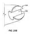
図21Bは、本開示の別の態様によるプランジャ144の側面斜視図である。図21Cは、ローリングダイヤフラム112と図21Bに示すプランジャ144との側面斜視図である。プランジャ144は、プランジャ144の遠位端に成形される溝206を有している。動作時、溝206は、側壁134の転動を容易にするために、ローリングダイヤフラム112の近位端132において側壁134または端壁の少なくとも一部を捕捉する。図21Cに示すように、溝206は、ローリングダイヤフラム112の近位端132に形成された突起208を受け入れるような形状とすることができる。溝206は、突起208の形状に対応するT字型形態を有することができる。限定されないが卵形、矩形、三角形等を含む種々の他の形状も企図される。図26Aおよび図26Bに示すようなさらなる態様では、溝206は、突起208を受け入れるような形状であるスロットの形態である。溝206は、プランジャ144およびローリングダイヤフラム112のうちの一方に配置され、突起208は、プランジャ144およびローリングダイヤフラム112の他方に配置されている。溝206は、突起208を一方向にのみ挿入することができるような形状である。溝206に挿入されると、ローリングダイヤフラム112に対してプランジャ144を係止するために、溝206に対して突起208を回転させることができる。溝206から突起208を取り除くために、突起208は、望ましくは、挿入方向に対応する方向に溝206と位置合わせされるように回転する。図23および図24に示すようなさらに別の態様では、プランジャ144およびローリングダイヤフラム112の他方のめねじ機構とねじ式に係合するプランジャ144およびローリングダイヤフラム112の一方におねじ機構を有するねじ切り部材210により、プランジャ144はローリングダイヤフラム112に接続される。おねじ機構およびめねじ機構の位置が反対になる実施形態も企図される。 FIG. 21B is a side perspective view of the
図22は、本開示の別の態様によるローリングダイヤフラムおよびプランジャの側断面図である。プランジャ144の遠位端は、ローリングダイヤフラム112の側壁134と係合するようにプランジャ144から半径方向外側に延在する突起211を有している。突起211は、プランジャ144が遠位方向に前進される際に折縁226の転動を容易にするようにローリングダイヤフラム112の折縁226と係合することができる。 FIG. 22 is a side sectional view of a rolling diaphragm and a plunger according to another aspect of the present disclosure. The distal end of the
図23および図24Aは、本開示の別の態様によるローリングダイヤフラム112およびプランジャ144の側断面図である。プランジャ144は、ローリングダイヤフラム112のめねじ機構とねじ式に係合するプランジャ144のおねじ機構を有するねじ切り部材210によって、ローリングダイヤフラム112に接続される。いくつかの態様では、ねじ切り部材210は、ローリングダイヤフラム112のおねじ機構とねじ式に係合するプランジャ144のめねじ機構を有する。 23 and 24A are side sectional views of the rolling
図24Bは、本開示の別の態様によるプランジャ144の斜視図であり、プランジャ144は第1の後退状態で示されている。図24Cは、第2の拡張状態で示されている図24Cに示すプランジャ144の斜視図である。プランジャ144は、遠位端に、第1の後退状態(図24Bに示す)から第2の拡張状態(図24C)まで半径方向外側に拡張可能な1つまたは複数の拡張可能リブ213を有している。1つまたは複数の拡張可能リブ213は、プランジャ144の遠位移動または近位移動に応じて自動的に拡張可能かつ後退可能であり得る。いくつかの態様では、1つまたは複数の拡張可能リブ213は、プランジャ144がローリングダイヤフラム112から流体を排出するように遠位方向に前進されるときに、ローリングダイヤフラム112(図示せず)の側壁134と係合するように半径方向外側に拡張することができる。他の態様では、1つまたは複数の拡張可能リブ213は、ローリングダイヤフラム112が空の折畳状態にあり、プランジャ144がローリングダイヤフラム112(図示せず)を流体で充填するように近位方向に後退されるとき、ローリングダイヤフラム112の側壁134と係合するように半径方向外側に拡張することができる。図25A~図25Cは、プランジャ144の非拡張部分に1つまたは複数のローラ215があるプランジャ144を示す。ローラ215は、ローリングダイヤフラム112(図25Cに示す)の側壁134と係合し、プランジャ移動方向において自由に回転可能であり得る。 FIG. 24B is a perspective view of the
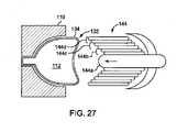
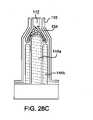
図27~図28Cは、本開示の他の態様によるローリングダイヤフラム112およびプランジャ144の側断面図である。プランジャ144は、互いに対して入れ子式の向きで配置された複数の同心部分144a~144dを有している。同心部分144a~144dの各々は、残りの同心部分144a~144dとは独立して近位方向または遠位方向に前進させることができる。一態様では、外側同心部分は、ローリングダイヤフラム112の近位端132を支持することができ、内側同心部分は、ローリングダイヤフラム112から流体を送達するために前進される。個々の同心部分144a~144dの移動を制御することにより、ローリングダイヤフラム112をより均一に圧縮し、ローリングダイヤフラム112から完全に流体を排出することができる。さらに、個々の同心部分144a~144dを近位方向に選択的に引き出すことにより、圧縮後にプランジャ144からローリングダイヤフラム112をより容易に取り除くことができる。 27-28C are side sectional views of the rolling
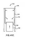
図29は、本開示の別の態様によるローリングダイヤフラムおよびプランジャの側断面図である。ローリングダイヤフラム112は、遠位端130に出口ポートが画定されていてもいなくても、可撓性容器として形成することができる。圧力ジャケット110内にローリングダイヤフラム112を保持し、ローリングダイヤフラム112の近位端132においてプランジャ144によってローリングダイヤフラム112に作用することができる。プランジャ144を遠位方向に移動させることにより、圧力ジャケット110の遠位側壁262に対してローリングダイヤフラム112が圧縮される。圧力ジャケット110の遠位側壁262に、シール266を有する穿孔要素264が設けられている。プランジャ144が圧力ジャケット110の遠位側壁262に対してローリングダイヤフラム112を圧縮すると、穿孔要素264は、ローリングダイヤフラム112の側壁134を穿孔して、流体流路セット108をローリングダイヤフラム112の内部容積114と流体連通させる。シール266は、側壁134の穿孔部分の周囲を封止して、圧力ジャケット110から流体が漏れないようにする。 FIG. 29 is a side sectional view of a rolling diaphragm and a plunger according to another aspect of the present disclosure. The rolling
図30は、本開示の別の態様によるローリングダイヤフラム112およびプランジャ144の側断面図である。ローリングダイヤフラム112は、プランジャ144と同時成形される。いくつかの態様では、プランジャ144は、剛性の実質的に非変形可能プランジャであり得るが、ローリングダイヤフラム112は、ローリングダイヤフラム112の内部容積114が拡張または収縮することができるようにそれ自体の上で転動することができる可撓性側壁134を有することができる。最初に、ローリングダイヤフラム112pは、プランジャ144と同時成形される予備成形された形態であり得る。ローリングダイヤフラム予備成形品112pをプランジャ144と同時成形した後、金型M内でのブロー成形技法により、ローリングダイヤフラム予備成形品112pをその最終形体まで拡張させることができる。たとえば、ストレッチブロー成形技法を用いて、ローリングダイヤフラム予備成形品112pを拡張させることができる。ローリングダイヤフラム予備成形品112pの少なくとも一部がブロー成形によって拡張する間、金型M内にプランジャ144を固定することができる。いくつかの態様では、ローリングダイヤフラム112の第2部分が拡張する間、金型M内にローリングダイヤフラムの第1部分が固定され、その拡張の間、プランジャ144は金型Mで移動することができる。別法として、ローリングダイヤフラム112をその最終的な拡張形状に成形することができ、プランジャ144をローリングダイヤフラム112と同時成形することができる。いくつかの態様では、近位端および遠位端等、ローリングダイヤフラム112の第1部分を予備成形することができ、一方で、ローリングダイヤフラム112の第2部分を、ストレッチブロー成形技法による等、拡張させることができる。 FIG. 30 is a side sectional view of the rolling
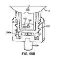
図31は、本開示の別の態様によるローリングダイヤフラム112およびプランジャ144の側断面図である。プランジャ144は、内側要素268と、内側要素268を包囲しかつ外側要素270に対して移動可能な外側要素270とを有している。外側要素270は、外側要素270の外周から半径方向外側に突出する1つまたは複数の把持要素246を有している。外側要素270の1つまたは複数の把持要素246は、折縁226においてローリングダイヤフラム112の側壁134と係合する。内側要素268または外側要素270の少なくとも一部と係合するとき、1つまたは複数の把持要素246は後退可能であり得る。プランジャ144は、一連の漸進的なストロークにおいて外側要素270に対して内側要素268を往復移動させる。各ストロークは、遠位成分および近位成分を有し、近位成分は遠位成分より長い。このように、プランジャ144は、近位方向に正味の移動を有する。プランジャ144の各遠位移動により、内側要素268は外側要素270に対して遠位に移動し、それにより、外側要素270における半径方向荷重が解放され、ローリングダイヤフラム112の側壁134から(外側要素270内に把持要素246を引き出すことによる等)把持要素246の把持力が低減する。したがって、外側要素270を遠位に前進させて、折縁226の遠位で側壁134と係合させることができる。プランジャ144の各近位移動により、内側要素268は外側要素270に対して近位に移動し、それにより、外側要素270の半径方向荷重が増大し、把持要素246がローリングダイヤフラム112の側壁134と係合する。外側要素270は、折縁226に達するまでローリングダイヤフラム112の側壁134を近位方向に引っ張り、折縁226に達した後、プランジャの移動が繰り返される。このように、ローリングダイヤフラム112の内部容積114を流体で充填することができる。流体は、本明細書に記載するようにローリングダイヤフラム112から排出することができる。いくつかの態様では、外側要素270は、ばね等の弾性的に偏向可能な要素を有する拡張可能要素とすることができ、それは、プランジャ144が外側要素270と係合すると、ローリングダイヤフラム112の側壁134と接触するように半径方向外側に拡張する。 FIG. 31 is a side sectional view of the rolling
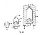
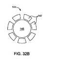
図32Aは、本開示の別の態様によるローリングダイヤフラム112およびプランジャ144の側断面図である。図32Bは、図32Aに示すプランジャ144の上面図である。プランジャ144は、中心部分145と、中心部分145に作動的に接続された複数の半径方向伸張可能要素147とを有している。中心部分145は、中心部分145の実質的に円錐形の遠位部分を画定する第1傾斜面145’を有している。半径方向伸張可能要素147の各々は、中心部分145の第1傾斜面145’に対応する第2傾斜面147’を有している。プランジャ144は、最初に、反転したローリングダイヤフラム112に挿入される。中心部分145が近位方向に移動することにより、中心部分145の第1傾斜面145’は、複数の半径方向伸張可能要素147のうちの少なくとも1つの第2傾斜面147’と係合する。第1傾斜面145’および第2傾斜面147’の勾配により、中心部分145の近位移動の結果として、半径方向伸張可能要素147の少なくとも1つに半径方向移動成分が加えられる。半径方向伸張可能要素147のうちの少なくとも1つのこうした半径方向移動により、プランジャ144が後退される際に、半径方向伸張可能要素147のうちの少なくとも1つの把持面147’’がローリングダイヤフラム112の側壁134の折畳み部分と係合する。 FIG. 32A is a side sectional view of the rolling
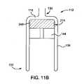
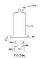
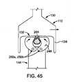
図33Aは、本開示の別の態様によるローリングダイヤフラム112およびプランジャ144の側断面図であり、プランジャ144は第1軸方向位置で示されている。図33Bは、図33Aに示すローリングダイヤフラム112およびプランジャ144の側断面図であり、プランジャ144は第2軸方向位置で示されている。ローリングダイヤフラム112の近位端132は、ローリングダイヤフラム112の近位端132において側壁134に対して半径方向外側に突出するリングとして形成されたプランジャ係合部分254を有している。プランジャ係合部分254は、ローリングダイヤフラム112の近位端132の周囲に連続的にまたは不連続に延在することができる。プランジャ144は、プランジャ144が遠位方向に移動すると、ローリングダイヤフラム112のプランジャ係合部分254と協働するように構成された半径方向内側窪み部分256を有している。いくつかの態様では、図33Aに示すように、圧縮されていないローリングダイヤフラム112において最初に半径方向外側方向に突出するプランジャ係合部分254は、プランジャ144の遠位方向の移動によりローリングダイヤフラム112の側壁134が折り畳まれたときに、図33Bに示すように半径方向内側に突出するように反転される。プランジャ係合部分254が半径方向内側方向に折り畳まれると、プランジャ144の窪み部分256は、プランジャ係合部分254を受け入れ、それにより、プランジャ係合部分254は、窪み部分256の遠位端のカラー258と窪み部分256の近位端のプランジャ基部260との間で軸方向に保持される。プランジャ144のカラー258は、プランジャ144をローリングダイヤフラム112のプランジャ係合部分254から解除することができるように、半径方向内側に後退可能であり得る。 FIG. 33A is a side sectional view of the rolling
図34Aは、本開示の別の態様によるローリングダイヤフラム112およびプランジャ144の側断面図であり、プランジャ144は第1軸方向位置で示されている。図34Bは、図34Aに示すローリングダイヤフラム112およびプランジャ144の側断面図であり、プランジャ144は第2軸方向位置で示されている。ローリングダイヤフラム112は、ローリングダイヤフラム112の近位端132に形成された第1係合部分244aを有している。第1係合部分244aは、プランジャ144と係合するように構成されている。いくかの態様では、第1係合部分244aは、近位端132の中心部分から近位に延在するタブとして形成されている。第1係合部分244aは、加熱による等、非変形可能であるかまたは変形可能であり得る。第1係合部分244は、プランジャ144に形成された第2係合部分244bに接続可能である。第2係合部分244bは、第1係合部分244aのタブを受け入れるように構成された凹部として形成することができる。いくつかの態様では、第2係合部分244aに第1係合部分244aを解除可能にまたは非解除可能に接続することができる。たとえば、第1係合部分244aの少なくとも一部を加熱することによる等、第1係合部分244aの少なくとも一部を第2係合部分244bに融着または接着することにより、第2係合部分244bに第1係合部分244aの少なくとも一部を永久的にかつ非解除可能に結合することができる。いくつかの態様では、スナップフィット接続を介してまたはねじ式接続を介して、第2係合部分244bに第1係合部分244aの少なくとも一部を解除可能に結合することができる。接続されると、第1係合部分244aおよび第2係合部分244bにより、プランジャ144が往復移動することができ、ローリングダイヤフラム112の充填または排出を可能にする。 FIG. 34A is a side sectional view of the rolling
いくつかの態様では、第1係合部分244aは、近位端132の中心部分から近位に延在するタブ244cとして形成されており、リップ244dが、タブ244cの近位端から半径方向外側に突出している。第1係合部分244aは、プランジャ144に形成された第2係合部分244dに接続可能である。第2係合部分244bは、第1係合部分244aのリップ244dと係合するように構成された一対の半径方向偏向可能フィンガ244eを有することができる。半径方向偏向可能フィンガ244eは、第2係合部分224bを第1係合部分244aに係止するように、プランジャ144が遠位に前進される際にリップ244dを通過するように第1位置から第2位置まで偏向可能であり得る。係止されると、フィンガ244eの少なくとも一部の周囲に延在するカラーにより、フィンガ244eの半径方向偏向を阻止することができる。いくつかの態様では、ローリングダイヤフラム112の充填中等、プランジャ144の近位方向の引戻し中に、フィンガ244eが第1係合部分244aからはずれないように、圧力ジャケット110(図2に示す)に対してフィンガ244eを係止することができる。 In some embodiments, the first engaging
図35は、本開示の別の態様によるローリングダイヤフラム112およびプランジャ144の側断面図である。プランジャ144は、第1端部144aおよび第2端部144bを有し、第1端部144aは第2端部144bに対して軸方向に移動可能である。第1端部144aおよび第2端部144bは、プランジャ144の長手方向軸に対して斜めに延在するウェビング144cによって互いに接続されている。第1端部144aが第2端部144bに向かって移動すると、ウェビング144cは、半径方向外側に拡張してローリングダイヤフラム112の側壁134と係合し、空のローリングダイヤフラム112の内側に面する壁の後退を可能にする。第2端部144bから離れるように第1端部144aが移動すると、ウェビング144cは、半径方向内側に収縮して、ローリングダイヤフラム112の側壁134から外れる。 FIG. 35 is a side sectional view of the rolling
図36Aは、本開示の別の態様によるプランジャ144の斜視図である。図36Bは、図36Aに示すプランジャ144とローリングダイヤフラム112との側断面図である。プランジャ144は、プランジャ144の本体に対して半径方向外側に突出する1つまたは複数の第1把持要素246aを有している。いくつかの態様では、1つまたは複数の第1把持要素246aは、プランジャ144の本体に接続された第1端部と、第1端部に対して半径方向外側に突出する第2端部とを有することができる。1つまたは複数の第1把持要素246aのうちの少なくとも1つを、ローリングダイヤフラム112(図示せず)の平滑な側壁134と係合するように構成することができる。図36Bに示す他の態様では、プランジャ144の1つまたは複数の第1把持要素246aのうちの少なくとも1つを、ローリングダイヤフラム112の側壁134に形成された対応する第2把持要素246bと係合するように構成することができる。第1把持要素246aと第2把持要素246bとの間の相互作用により、ローリングダイヤフラム112のプランジャ144と側壁134との間の接触面において把持力が増大する。1つまたは複数の把持要素は、図43に示すように、プランジャ144の本体に対して(半径方向伸張により)係合するかまたは(半径方向後退により)係合解除する能動的な把持要素であり得る。いくつかの態様では、プランジャ144の近位移動中に意図せずに外れないように、プランジャ144およびローリングダイヤフラム112の長手方向軸に対して、第1把持要素246aおよび第2把持要素246bのうちの少なくとも1つに角度をつけることができる。 FIG. 36A is a perspective view of the
図37は、本開示の別の態様によるローリングダイヤフラム112およびプランジャ144の側断面図である。プランジャ144は第1ねじ切り部分240aを有し、一方で、ローリングダイヤフラム112の側壁134の内側に面する外側部分が、プランジャ144の第1ねじ切り部分240aとねじ式に係合することができる第2ねじ切り部分240bを有している。いくつかの態様では、第1ねじ切り部分240aが第2ねじ切り部分240bと係合することができるように、プランジャ144を、その長手方向軸を中心に回転させ、長手方向軸に沿って直線状に移動させることができる。係合すると、プランジャ144を回転なしに軸方向に引き出されるように移動させることができる。第1ねじ切り部分240aと第2ねじ切り部分240bとの間のねじ式係合は、ローリングダイヤフラム112が、折畳み形態から近位方向に引き出されてローリングダイヤフラム112の内部容積114を流体で充填する際に、ローリングダイヤフラム112の側壁134に対してプランジャ144の把持力を増大させるのに役立つ。いくつかの態様では、第1ねじ切り部分240aおよび第2ねじ切り部分240bのうちの少なくとも一方は、ローリングダイヤフラム112のピストンおよび側壁134それぞれの周囲の少なくとも一部にわたって不連続であり得る。他の態様では、第1ねじ切り部分240aおよび第2ねじ切り部分240bは、プランジャ144およびローリングダイヤフラム112それぞれの長手方向軸を中心にらせん状に延在することができる。さらなる態様では、第1ねじ切り部分240aおよび第2ねじ切り部分240bは、プランジャ144およびローリングダイヤフラム112のうちの一方の複数の円形隆起と、プランジャ144およびローリングダイヤフラム112のうちの他方の対応する円形溝として形成することができる。FIG. 37 is a side sectional view of the rolling
図38は、本開示の別の態様によるローリングダイヤフラムおよびプランジャの側断面図である。ローリングダイヤフラム112の側壁134の折り畳まれた内側に面する部分とプランジャ144との間に、環状部材242を配置することができる。プランジャ144が近位方向に引き出されるときに側壁134の曲げおよび座屈を防止するために、ローリングダイヤフラム112の側壁134に対して拡張するように、環状部材242に加圧することができる。いくつかの実施形態では、環状部材242は、本明細書に記載するローリングダイヤフラム112の転動と同様にそれ自体の上で転動することができる。 FIG. 38 is a side sectional view of a rolling diaphragm and a plunger according to another aspect of the present disclosure. An
図39Aは、本開示の別の態様によるローリングダイヤフラム112およびプランジャ144の側断面図であり、プランジャ144は第1軸方向位置で示されている。図39Bは、図39Aに示すローリングダイヤフラム112およびプランジャ144の側断面図であり、プランジャ144は第2軸方向位置で示されている。ローリングダイヤフラム112は、ローリングダイヤフラム112の近位端132に形成された第1係合部分244aを有している。第1係合部分244aは、プランジャ144と係合するように構成されている。いくつかの態様では、第1係合部分244aは、近位端132の中心部分から近位に延在する1つまたは複数の脚244cとして形成されている。脚244cの各々は、その近位端において半径方向に延在する棚244dを有している。第1係合部分244aは、プランジャ144に形成された第2係合部分244bに接続可能である。第2係合部分244bは、第1係合部分244aの脚244cおよび棚244dを受け入れるように構成された凹部として形成することができる。いくつかの態様では、第2係合部分244bに第1係合部分244aを解除可能に接続することができる。たとえば、プランジャ144の第2係合部分244bは、ローリングダイヤフラム112の第1係合部分244aを選択的に係止するように移動可能な、移動可能係止要素244eを有することができる。いくつかの態様では、係止要素244eは、脚244cおよび棚244dを第2係合部分244bの凹部から引き出すことができるように、半径方向において直線状に移動可能であり得る。他の態様では、係止要素244eは、脚244cおよび棚244dが第2係合部分244bの凹部内で係止される係止位置と、脚244cおよび棚244dを第2係合部分244bの凹部から引き出すことができる係止解除位置との間で枢支点を中心に枢動可能であり得る。接続されると、第1係合部分244aおよび第2係合部分244bにより、プランジャ144は往復移動することができ、ローリングダイヤフラム112の充填または排出を可能にする。いくつかの態様では、バヨネット接続を用いて、第1係合部分244aおよび第2係合部分244bのうちの一方を第1係合部分244aおよび第2係合部分244bのうちの他方に対して回転させることにより、第1係合部分244aおよび第2係合部分244bを接続することができる。 FIG. 39A is a side sectional view of the rolling
図41Aは、本開示の別の態様によるローリングダイヤフラム112およびプランジャ144の側断面図であり、プランジャ144は第1軸方向位置で示されている。図41B~図42Cは、図41Aに示すローリングダイヤフラム112およびプランジャ144の側断面図であり、プランジャ144は、それぞれ第2軸方向位置および第3軸方向位置で示されている。ローリングダイヤフラム112は、圧縮されていないローリングダイヤフラムの外径より大きい内径を有する圧力ジャケット110内に配置され、それにより、圧力ジャケット110の内部側壁とローリングダイヤフラム112の側壁134の外側部分との間に空間Sがもたらされる。プランジャ144がローリングダイヤフラム112の遠位端130に向かって前進される際に、ローリングダイヤフラム112の側壁134は圧縮され、それにより、側壁134は、半径方向外側に拡張し、圧力ジャケット110の内部側壁と係合する。望ましくは、ローリングダイヤフラム112は、ローリングダイヤフラム112の出口においてまたは管セット(図示せず)内で所定圧力に達するまで、ローリングダイヤフラム112の内部容積114から流体が送達されないようにする高亀裂圧力弁とともに使用される。プランジャ144を遠位方向にさらに移動させることにより、ローリングダイヤフラム112の側壁134がさらに圧縮され、側壁134の弾性限界内で維持しながら側壁134に対する全ひずみを増大させる。 FIG. 41A is a side sectional view of the rolling
図42は、本開示の別の態様によるローリングダイヤフラム112およびプランジャ144の側断面図である。プランジャ144は、本明細書に記載するようなローリングダイヤフラム112の側壁134の内部部分と係合するように往復移動可能な外部部分143aを有している。プランジャ144は、外部部分143aに対して独立して移動可能な内部部分143bをさらに有している。外部部分143aは、ローリングダイヤフラム112の側壁134と接触するまで遠位に移動する。その後、内部部分143bは遠位に前進され、ローリングダイヤフラム112の側壁134を圧縮してローリングダイヤフラム112の内部容積114から流体を送達する。したがって、内部部分143bは近位に後退し、一方で外部部分143aは遠位に移動する。ローリングダイヤフラム112の内部容積114から流体を排出するようにする内部部分143bの移動は、連続的に行うことができる。プランジャ144は、外部部分143aに対して半径方向内側に突出する1つまたは複数の第1把持要素246aを有している。プランジャ144の1つまたは複数の第1把持要素246aのうちの少なくとも1つを、ローリングダイヤフラム112の側壁134に形成された対応する第2把持要素246bと係合するように構成することができる。第1把持要素246aと第2把持要素246bとの間の相互作用により、プランジャ144とローリングダイヤフラム112の側壁134との間の接触面における把持力が増大する。 FIG. 42 is a side sectional view of the rolling
図44は、本開示の別の態様によるローリングダイヤフラム112およびプランジャ144の側断面図である。プランジャ144は、共通枢支点250を中心に枢動可能である一対の枢動可能要素248を有している。枢動可能要素248の近位端248aを互いに向かって移動させることにより、遠位端248bは、互いにから離れてかつローリングダイヤフラム112の側壁134と係合するように移動する。逆に、枢動可能要素248の近位端248aを互いにから離れるように移動させることにより、遠位端248bは、互いに向かってかつローリングダイヤフラム112の側壁134と係合しなくなるように移動する。図45において、枢動可能要素248は、第1枢支点250aおよび第2枢支点250bを中心に枢動可能である。枢動可能要素248は、ローリングダイヤフラム112の近位端132から突出する係合部分244と係合するように半径方向内側に枢動可能である。いくつかの実施形態では、第1枢支点250aおよび第2枢支点250bは同じであり得る。 FIG. 44 is a side sectional view of the rolling
図46Aは、本開示の別の態様によるプランジャ144の側断面図である。図46Bは、ローリングダイヤフラム112と図46Aに示すプランジャ144との側断面図である。プランジャ144は、全体として参照により本明細書に組み込まれる、Reillyらの米国特許第5,383,858号明細書、Hitchinsらの同第5,873,861号明細書およびTrockiらの同第6,652,489号明細書に記載する接続機構を有するピストン178と係合するように構成された接続インタフェース254Aを有している。ピストン178は、ピストン178に対するプランジャのその長手方向軸を中心とする向きに関わらずプランジャ144と解除可能に係合するように適合された少なくとも1つの取付部材を有している。いくつかの態様では、プランジャ144は、プランジャ144の本体の少なくとも一部を覆うカバー280を有している。カバー280は、本体282の溝286と係合するリップ284によって本体282と保持される。本体282は、ピストン178から可逆的に伸張可能な1つまたは複数のピン290を受け入れる環状隆起288をさらに有している。1つまたは複数のピン290がピストン178から半径方向外側に延在するとき、ピン290のうちの少なくとも1つが環状隆起288の内側に受け入れられる。このように、ピストン178が近位または遠位に移動することにより、環状隆起288内にピン290のうちの少なくとも1つが係合する結果として、プランジャ144が対応して移動する。1つまたはピン290を半径方向内側方向に後退させることにより、1つまたは複数のピン290が環状隆起288から解除され、ピストン178をプランジャ144から解除することができる。FIG. 46A is a side sectional view of the
図47Aは、本開示の別の態様によるローリングダイヤフラム112およびプランジャ144の側断面図であり、プランジャ144は第1軸方向位置で示されている。図47Bは、図47Aに示すローリングダイヤフラム112およびプランジャ144の側断面図であり、プランジャ144は第2軸方向位置で示されている。ローリングダイヤフラム112は、近位端132から遠位端130に向かって半径方向外側に延在する円錐形状を有している。側壁134の外周は、側壁134の周囲に巻かれ、近位端132と遠位端130との間で延在する、ばね等の弾性要素252を有している。弾性要素252は、プランジャ144と係合すると、ローリングダイヤフラム112の側壁134の転動と同様にそれ自体の上で転動するように構成されている。いくつかの態様では、弾性要素252は、強化エラストマーばねまたは金属メッシュであり得る。 FIG. 47A is a side sectional view of the rolling
図48Aは、本開示の別の態様による、圧力ジャケット110、ローリングダイヤフラム112およびプランジャ144を有するシリンジの部分組立分解斜視図である。図48Bは、図48Aに示すシリンジの側断面図である。図48Aおよび図48Bに示すシリンジ104の構成要素は、図2および図3を参照して上述したシリンジ104の構成要素と実質的に同様である。図48Aおよび図48Bにおける参照数字は、図2および図3における対応する参照数字と同一の構成要素を示すために使用されている。図2および図3において概して示すシリンジ104に関する先の考察は、図48Aおよび図48Bに示す態様に適用可能であるため、これらのシステムの関連する相違のみを以下考察する。 FIG. 48A is a partially assembled disassembled perspective view of a syringe having a
図48Aおよび図48Bは、患者に送達する流体で予め充填される使い捨ての単回使用シリンジ104を示す。シリンジ104は、図2を参照して上述したように、注入器102とインタフェースする使い捨て圧力ジャケット110を含む。圧力ジャケット110の近位端118は、ローリングダイヤフラム112の端壁136と係合するプランジャ144を有している。プランジャ144は、ローリングダイヤフラム112の端壁136と係合する遠位端146と、注入器102のピストンヘッド138と係合するような形状である近位端148とを有している。圧力ジャケット110の近位端118には、シール150が設けられている。シール150は、注入器102(図48および図48Bには示さず)で使用する前に圧力ジャケット110の近位端118を封止する。さらに、シール150は、防湿材を提供する。望ましくは、シール150は、注入器102にシリンジ104を接続する前に取り除かれる。シリンジ104は、ローリングダイヤフラム112の遠位端130に設けられたキャップ152をさらに含む。キャップ152は、ローリングダイヤフラム112の遠位端130に成形し、接着し、ねじ込み、または他の方法で機械的に結合することができる。望ましくは、典型的な注入圧力に耐えるために、キャップ152とローリングダイヤフラム112の遠位端130との間に接続部が形成される。キャップ152は、流体流路セット(図示せず)に接続する、ルアー型コネクタ等のコネクタ154を有している。一態様では、流体流路セットは、キャップ152のコネクタ154に結合する対応するコネクタを含む。たとえば、流体流路セットに穿孔針156を設けて、キャップ152およびローリングダイヤフラム112の排出ポート142を穿孔してローリングダイヤフラム112の内部容積114を流体流路セットと流体接続することができる。望ましくは、流体流路セットは、使用後にローリングダイヤフラム112とともに廃棄される。 48A and 48B show a disposable single-
図49Aは、本開示の別の態様による圧力ジャケット110、ローリングダイヤフラム112およびプランジャ144を有するシリンジ104の部分組立分解斜視図である。図49Bは、図49Aに示すシリンジ104の側断面図である。 FIG. 49A is a partially assembled disassembled perspective view of a
図49Aおよび図49Bに示すシリンジ104の構成要素は、図48Aおよび図48Bを参照して上述したシリンジ104の構成要素と実質的に同様である。図49Aおよび図49Bにおける参照数字は、図48Aおよび図48Bにおける対応する参照数字と同一の構成要素を示すために使用されている。図48Aおよび図48Bにおいて概して示すシリンジ104に関する先の考察は、図49Aおよび図49Bに示す態様に適用可能であるため、これらのシステムの関連する相違のみを以下考察する。圧力ジャケット110は、種々のローリングダイヤフラム112と使用することができる再使用可能圧力ジャケット110であり得る。望ましくは、圧力ジャケット110は、実質的に円錐形であり、少なくともローリングダイヤフラム112の側壁134に沿って延在するように注入器102に取外し可能に接続可能である。圧力ジャケット110の遠位端116からローリングダイヤフラム112を装填することができる。キャップ152は、ローリングダイヤフラム112の遠位端130から側壁134の少なくとも一部まで延在するように形成される。キャップ152は、キャップ152の外面から半径方向外側に延在する少なくとも1つの係止タブ158を含む。係止タブ158は、注入器102に設けられた係止カラー160と係合するように形成されている。係止カラー160は、使用中は係止タブ158と係合させ、ローリングダイヤフラム112を圧力ジャケット110から取り除くべきときに係止タブ158から分離することができるように、後退可能である。プランジャ144は、再使用可能であり、かつ圧力ジャケット110の軸に沿った遠位方向における軸方向移動により半径方向に拡張する。プランジャ144に対して、1つまたは複数のばね162によってピストンヘッド138に対してばね荷重を与えることができる。ピストンヘッド138を近位方向に引き出すと、ばね162はプランジャ144をピストンヘッド138から押し離し、プランジャ144が近位方向に引き出される際にプランジャ144の直径を低減させることができる。一態様では、圧縮空気の噴出、またはローリングダイヤフラム112を容易に廃棄するために小型サイズに押しつぶす機械的ピストンの作用等、除去部材によって、使用済みローリングダイヤフラム112を圧力ジャケット110から取り除くことができる。 The components of the
図50Aは、本開示の別の態様による、圧力ジャケット110、ローリングダイヤフラム112(図示せず、圧力ジャケット110内)およびプランジャ144を有するシリンジ104の部分組立分解斜視図である。いくつかの態様では、圧力ジャケット110は、合わせて蝶番式に接続される2つの円筒状半体110a、110bから形成されている。圧力ジャケット110の長手方向軸と実質的に平行に蝶番166を設けることができ、または近位端118もしくは遠位端116に長手方向軸に対して実質的に垂直に、蝶番166を設けることができる。圧力ジャケット110を開放しローリングダイヤフラムのより容易な装填を可能にするように、蝶番の作用により、円筒状半体110a、110bの一方を他方に対して枢動させることにより、圧力ジャケット110を開放することができる。装填されると、注入器102に接続する前に圧力ジャケット110を閉鎖することができる。図50Bを参照すると、別の態様による圧力ジャケット110が示されている。この態様では、圧力ジャケット110は、クラムシェル形態で互いに接合される2つの円筒状半体110a、110bから形成される。圧力ジャケット110の遠位端116に、フィンガロック194が設けられている。ローリングダイヤフラム112をより容易に装填することができるように、円筒状半体110a、110bのうちの一方を他方に対して揺動させることにより、圧力ジャケット110を開放することができる。装填されると、注入器102(図示せず)に接続する前に圧力ジャケット110を閉鎖することができる。FIG. 50A is a partially assembled disassembled perspective view of a
図51は、本開示の別の態様による、圧力ジャケット110、ローリングダイヤフラム112およびプランジャ144を有するシリンジ104の側断面図である。圧力ジャケット110は、圧力ジャケット110の遠位端116を囲む取外し可能閉鎖具196を有している。閉鎖具196は、圧力ジャケット110内にローリングダイヤフラム112を装填するために、圧力ジャケット110の遠位端116から取り外し可能であり得る。ローリングダイヤフラム112が装填されると、圧力ジャケット110の遠位端116は、閉鎖具196によって閉鎖される。たとえば、閉鎖具196は、圧力ジャケット110の遠位端116の対応するねじ山と係合するめねじまたはおねじを有することができる。別法として、閉鎖具196は、圧力ジャケット110の遠位端116の対応するスロットまたはタブと係合するタブまたはスロットを有するバヨネット型閉鎖具であり得る。閉鎖具196は、流体流路セット(図示せず)に接続するねじ切り取付具を有することができる。 FIG. 51 is a side sectional view of a
図52Aおよび図52Bは、本開示の別の態様による、圧力ジャケット110、ローリングダイヤフラム112およびプランジャ144を有するシリンジ104の部分組立分解側断面図である。図52Aおよび図52Bに示すシリンジ104の構成要素は、図48Aおよび図48Bを参照して上述したシリンジ104の構成要素と実質的に同様である。図52Aおよび図52Bにおける参照数字は、図48Aおよび図48Bにおける対応する参照数字と同一の構成要素を示すために使用されている。図48Aおよび図48Bにおいて概して示すシリンジ104に関する先の考察は、図52Aおよび図52Bに示す態様に適用可能であるため、これらのシステムの間の関連する相違のみを以下考察する。図52aは、実質的に円筒状の圧力ジャケット110を有するシリンジ104を示す。さまざまな実施形態によれば、キャップ152は、キャップ152に取外し可能に接続される閉鎖部材168を有している。閉鎖部材168は、任意選択的に、キャップ152と一体的に形成することができ、一方で依然としてキャップ152に取外し可能に接続される。使用する前に、閉鎖部材168は、キャップ152と係合してキャップ152を封止し、その汚染を防止する。したがって、閉鎖部材168は取り除かれて、キャップ152を穿孔部材156で穿孔し流体流路セット(図示せず)に接続することができる。使用後、いかなる残りの流体もキャップ152からこぼれないように、キャップ152に閉鎖部材168を再接続することができる。 52A and 52B are partial assembly disassembled side sectional views of a
図53は、本開示の別の態様によるシリンジ104の側断面図である。シリンジ104は、圧力ジャケット110内に封入されるローリングダイヤフラム112を有し、流体スリーブ184がローリングダイヤフラム112の側壁134と圧力ジャケット110との間に配置されている。流体スリーブ184は、圧力ジャケット110内に配置された後のローリングダイヤフラム112の周囲で充填される。キャップ152は、圧力ジャケット110内で流体スリーブ184を密閉する。圧力ジャケット110の近位端から流体スリーブ184が漏れないように、圧力ジャケット110の近位端を第2キャップ186で封止することができる。 FIG. 53 is a side sectional view of the
図55Aおよび図55Bは、本開示の別の態様によるシリンジ104の側断面図である。図55Aおよび図55Bを参照すると、流体スリーブ184は、圧力ジャケット内でローリングダイヤフラム112を包囲するバッグの形態で(図55A)、またはローリングダイヤフラム112に対して近位のバッグとして(図55B)であり得る。プランジャ144は、ローリングダイヤフラム112からの流体が送達された後にプランジャ144の後退を可能にする逆止め弁188を有している。流体スリーブ184またはローリングダイヤフラム112の破断を検出するために、圧力ジャケット110内にセンサ190を設けることができる。図55Aを参照すると、ローリングダイヤフラム112は、ローリングダイヤフラム112の長手方向長さに沿って設けられた、対応する形状の流体スリーブ184を有している。一態様では、流体スリーブ184は、ローリングダイヤフラム112のミラーコピーであり得る。注入器102(図示せず)に挿入されるとき、ローリングダイヤフラム112は、流体流路セット(図示せず)に流体接続される。注入処置中、流体スリーブ184は、ローリングダイヤフラム112の内部容積114から流体を押し出す圧縮面として機能する。特に、プランジャ144等の注入器102の一部が、ローリングダイヤフラム112に対して流体スリーブ184を圧縮するように流体スリーブ184に作用する。このように、流体スリーブ184の圧縮力は、ローリングダイヤフラム112の表面全体にわたって均一に分散され、ローリングダイヤフラム112内に残っている流体の残留量を最小限にする。アセンブリの取扱を容易にするために、流体スリーブ184およびローリングダイヤフラム112の一方または両方の側方部分に、把持タブ192を設けることができる。 55A and 55B are side sectional views of the
図56Aおよび図56Bは、本開示の別の態様によるシリンジ104の側断面図である。ローリングダイヤフラム112は、ローリングダイヤフラム112の遠位端130に成形し、接着し、ねじ込み、または他の方法で機械的に結合することができるキャップ152を有する。望ましくは、典型的な注入圧力に耐えるように、ローリングダイヤフラム112のキャップ152と遠位端130との間に接続部が形成される。キャップ152は、流体流路セット108に接続する、ルアー型コネクタ等のコネクタ154を有している。一態様では、流体流路セットは、キャップ152のコネクタ154に結合するための対応するコネクタを含む。ローリングダイヤフラム112の排出ポート142を封止する、キャップ152の脆弱シール200の穿孔を可能にするために、流体流路セット108に穿孔針156が設けられている。図56Bに示す態様では、キャップ152内に穿孔針156を組み込むことができる。脆弱シール200が穿孔されると、ローリングダイヤフラム112の内部容積114は、流体流路セット108と流体接続される。図54を参照すると、ローリングダイヤフラム112は、その遠位端130に高圧シール202を有し、キャップ152は低圧シール204を有している。 56A and 56B are side sectional views of the
図58Aは、本開示の別の態様によるシリンジの側断面図である。図58Bは、図58Aに示すシールの部分断面斜視図である。ローリングダイヤフラム112の排出首部140は、二重シール構成をもたらすようにキャップ152のシール200aに当接するシール200を有している。キャップ152は、望ましくは、本明細書に記載する複数の方法のうちの1つで排出首部140に取り付けられる。キャップ152は、流体流路セット108のめねじとねじ式に係合する複数のおねじとして形成された接続部材212を有している。ローリングダイヤフラム112の内部容積114と流体流路セット108との間に流体連通を確立するために、二重シール構成に穿孔するように、流体流路セット108の終端部に穿孔針156が形成されている。 FIG. 58A is a side sectional view of the syringe according to another aspect of the present disclosure. FIG. 58B is a partial cross-sectional perspective view of the seal shown in FIG. 58A. The
図59を参照すると、本開示の別の態様によるシリンジの側断面図である。ローリングダイヤフラム112の排出首部140は最初に封止されている。キャップ152の穿孔針156が排出首部140においてローリングダイヤフラム112の側壁134に穿孔することができるように、キャップ152は圧力ジャケット110に取付可能である。いくつかの態様では、キャップ152は、流体流路セット108(図示せず)のめねじとねじ式に係合する複数のおねじとして形成された接続部材212を有することができる。ローリングダイヤフラム112の内部容積114間で流体連通を確立するために、ローリングダイヤフラム112の側壁134に穿孔するように、キャップ152の終端部に穿孔針156が形成されている。 FIG. 59 is a side sectional view of the syringe according to another aspect of the present disclosure. The
図60Aは、本開示の別の態様によるシリンジおよびローリングダイヤフラムとともに使用されるシールの側断面図であり、シール穿孔要素が第1封止位置で示されている。図60Bは、図60Bに示すシールの側断面図であり、シール穿孔要素は第2穿孔位置で示されている。シール150は、基部151と、基部151に対して実質的に垂直に突出する側壁153とを有することができる。基部151は、流体流路セットに設けられたスパイク等、穿孔要素155によって穿孔可能である。穿孔要素155が基部151を穿孔すると、基部151は、シール150の周囲を流体封止する。さらに、穿孔要素155の本体157は、シール150の側壁153と係合して二次シールを提供する。 FIG. 60A is a side sectional view of a seal used with a syringe and rolling diaphragm according to another aspect of the present disclosure, in which the seal perforation element is shown at the first sealing position. FIG. 60B is a side sectional view of the seal shown in FIG. 60B, in which the seal perforation element is shown at the second perforation position. The
図61は、本開示の別の態様によるローリングダイヤフラム112およびプランジャ144の側断面図である。プランジャ144は、内側要素300と内側要素300の少なくとも一部の周囲に巻きつけられた弾性要素310とを有している。近位端310aまたは遠位要素310b等の弾性要素310の一端は内側要素300に固定することができ、弾性要素310の反対側の端部は、内側要素300を中心に自由に回転することができる。弾性要素310の一端が内側要素300を中心に、右回り方向または左回り方向等、第1方向に回転すると、弾性要素310は、半径方向外側に拡張して、内側要素300および弾性要素310を包囲する外側要素320の内面と係合することができる。外側要素320は、その長手方向軸に沿ってスリットが延在する分割円筒体として形成することができる。外側要素320の外面は、ローリングダイヤフラム112の側壁134と係合する。したがって、弾性要素310が外側要素320の内面に対して拡張する際に、外側要素320は、その外面がローリングダイヤフラム112の側壁134と係合するように、半径方向外側に拡張する。このように、プランジャ144は、ローリングダイヤフラム112の内部容積114から流体を引き出すかまたは流体を排出するように、ローリングダイヤフラム112の側壁134を移動させることができる。いくつかの態様では、弾性要素310は、拡張状態で、ローリングダイヤフラム112の側壁134と係合することができる。弾性要素310を内側要素300の周囲で第1方向とは反対の第2方向に回転させると、弾性要素310は半径方向内側に収縮することができ、それにより外側要素320を係合解除する。いくつかの態様では、弾性要素310は、収縮状態では、ローリングダイヤフラム112の側壁134を係合解除することができる。 FIG. 61 is a side sectional view of the rolling
図62は、本開示の別の態様による圧力ジャケット110の側断面図である。圧力ジャケット110は、圧力ジャケット110を注入器102と解除可能に接続するアダプタ110aを有することができる。圧力ジャケット110の外側側壁は、外側側壁に対して半径方向外側に突出する1つまたは複数のタブ330を有している。1つまたは複数のタブ330は、対応するスロット340またはアダプタ110aに形成された係合機構に受け入れられる。いくつかの態様では、圧力ジャケット110をアダプタ110aの中心開口部内に挿入し、タブ330がスロット340内に受け入れられるまで、圧力ジャケット110をアダプタ110aに対して第1方向に(右回り方向または左周り方向に1/4回転等)回転させることにより、アダプタ110aに圧力ジャケット110を固定することができる。受け入れられると、圧力ジャケット110が第1方向と反対の第2方向に(左回り方向または右周り方向に1/4回転等)回転するまで、タブ330は、圧力ジャケット110をアダプタ110aと係止された状態で維持する。アダプタ110aは、流体が注入器102内に滴下しないように、外側側壁から突出する半径方向フランジ350を有することができる。注入器102の対応する係止機構とアダプタ110aを取外し可能に係止するために、アダプタ110aに1つまたは複数の係止要素360を設けることができる。いくつかの態様では、アダプタ110aは、バヨネット接続による等、注入器102に取外し可能に係止することができる。 FIG. 62 is a side sectional view of the
図63Aは、本開示の別の態様による、圧力ジャケット110を有するシリンジの斜視図である。図63Bは、図63Aに示すシリンジの側断面図である。図63Cは、図63Aに示す圧力ジャケット110と使用されるローリングダイヤフラム112の斜視図である。シリンジ104は、本明細書に記載するように、注入器102(図1に示す)と取外し可能にインタフェースする圧力ジャケット110を含む。圧力ジャケット110は、遠位端116と、近位端118と、貫通孔121(図63Bに示す)を画定するように、圧力ジャケット110の長手方向軸に沿って遠位端116と近位端118との間に延在する側壁119とを有している。いくつかの態様では、圧力ジャケット110の側壁119は、貫通孔121内にローリングダイヤフラム112(図63Bに示す)の少なくとも一部を受け入れるような形状である。圧力ジャケット110は、典型的には再使用可能構成要素であり、ローリングダイヤフラム112は、典型的には単回使用構成要素である。別の態様では、ローリングダイヤフラム112が流体で再充填可能であるように、ローリングダイヤフラム112は再使用可能であり得る。圧力ジャケット110の側壁119は、ローリングダイヤフラム112の少なくとも一部を受け入れる第1遠位部分360aと、注入器102とインタフェースする第2近位部分360bとを有している。いくつかの態様では、第2遠位部分360bは、第2近位部分360bの外面から半径方向外側に突出する係止ラグまたはリップ370を有している。係止ラグまたはリップ370は、第2近位部分360bの外周に連続的にまたは不連続に延在することができる。いくつかの態様では、係止ラグまたはリップ370は、開示内容が全体として参照により本明細書に組み込まれる、Reillyらの米国特許第5,383,858号明細書、Hitchinsらの同第5,873,861号明細書およびTrockiらの同第6,652,489号明細書、「Self-Orienting Syringe and Syringe Interface」という名称の米国特許出願第14/526,294号明細書、ならびに「Self-Orienting Syringe and Syringe Interface」という名称の米国特許出願第14/526,395号明細書に記載する流体注入器102の対応する係止機構に、圧力ジャケット110を解除可能に固定するように、接続インタフェースを有することができる。FIG. 63A is a perspective view of a syringe with a
図63Bを参照すると、圧力ジャケット110は、遠位端116に解除可能に固定されているキャップ390を有する。いくつかの態様では、ねじ式係合、バヨネット継手、または別の機械的締結構成により、圧力ジャケット110の遠位端116にキャップ390を固定することができる。たとえば、キャップ390は、圧力ジャケット110の少なくとも1つの溝440内に受け入れられる少なくとも1つの突起430を有することができ、それにより、少なくとも1つの突起430を溝440内にはまるように位置合わせすることにより、圧力ジャケット110にキャップ390を係止することができる。いくつかの態様では、キャップ390は、キャップ390を形成するように互いに接合される2つ以上の別個の要素から形成することができる。たとえば、キャップ390は、キャップ390の長手方向断面において互いに接合された2つの要素を有することができる。キャップ390の要素を保持するために、別個の要素の少なくとも一部の周囲にリングを設けることができる。キャップ390は、キャップ390を通って延在するノズル410とともに内側要素400を有することができる。ノズル410は、ローリングダイヤフラム112と流体連通して、ローリングダイヤフラム112内にまたはローリングダイヤフラム112から流体を送達することができる。ノズル410は、流体流路セット108(図1に示す)のコネクタ420に取外し可能に接続する接続インタフェースを有することができる。キャップ390は、ノズル410および/またはコネクタ420から滴下する可能性があるいかなる流体も収集するポケット450を有することができる。 Referring to FIG. 63B, the
図63Cを参照すると、キャップ390に、ローリングダイヤフラム112の少なくとも一部を取外し可能に固定することができる。いくつかの態様では、キャップ390の内部側壁は、ローリングダイヤフラム112の対応するねじ山140b(図5Aに示す)と係合する1つまたは複数のねじ山440A(図64Bに示す)を有することができる。他の態様では、スナップフィット、締り嵌め、接着接続、同時成形または他の任意の機械的締結構成によって、キャップ390にローリングダイヤフラム112を固定することができる。ローリングダイヤフラム112は、組込みキャップ390を有することができる。ローリングダイヤフラム112は、流体で予め充填することができ、または流体で充填することができるように空であり得る。さまざまな態様において、キャップ390にローリングダイヤフラム112を、取外し可能にまたは取外し不可能に接続することができる。望ましくは、ローリングダイヤフラム112は、圧力ジャケット110の貫通孔121に挿入される前にキャップ390に固定される。圧力ジャケット110にキャップ390を固定した後、プランジャ144(図2に示す)は、本明細書に記載するように、ローリングダイヤフラム112と係合して、ローリングダイヤフラム112内にまたはローリングダイヤフラム112から流体を送達することができる。With reference to FIG. 63C, at least a portion of the rolling
図64Aは、図63Aに示す圧力ジャケット110と使用されるキャップ390に対する代替実施形態の上面斜視図である。キャップ390は、ローリングダイヤフラム112をキャップ390に接続するねじ切りインタフェースを備えた一体型構造を有することができる。 FIG. 64A is a top perspective view of an alternative embodiment for the
上述した説明では、流体送達システムおよびそのために使用されるローリングダイヤフラムを有するシリンジの態様を提供したが、当業者は、本開示の範囲および趣旨から逸脱することなく、これらの態様に対する変更形態および改変形態をなし得ることができる。したがって、上述した説明は、限定するのではなく例示するように意図されている。上述した開示は、添付の特許請求の範囲によって定義され、請求項の均等性の意味および範囲内にある本開示に対するすべての変更形態はそれらの範囲内に包含されるべきである。 Although the above description has provided embodiments of a syringe with a fluid delivery system and a rolling diaphragm used therein, one of ordinary skill in the art will modify and modify these embodiments without departing from the scope and intent of the present disclosure. It can be in the form. Therefore, the above description is intended to be exemplary rather than limiting. The above-mentioned disclosures are defined by the scope of the appended claims, and all modifications to the present disclosure within the meaning and scope of the claims should be included within those scopes.
さらに、本発明では以下の例を含むことも好ましい。
[項1]
医療流体をその中に受け入れるローリングダイヤフラムであって、
プランジャと係合する端壁を備えた近位端と、圧力ジャケットの貫通孔内に受け入れられる遠位端であって、ノズルを有する遠位端と、長手方向軸に沿って前記近位端と前記遠位端との間に延在する側壁とを備え、前記側壁および前記端壁のうちの少なくとも一方の少なくとも一部が不均一な厚さを有し、
前記側壁が、前記プランジャによって作用されるとそれ自体の上で転動し、それにより、前記プランジャが前記近位端から前記遠位端に前進される際に、折畳み領域における前記側壁の外面が半径方向内側方向に折り畳まれるように、前記側壁の少なくとも一部が可撓性を有し、前記プランジャが前記近位端から前記遠位端に後退される際に、前記折畳み領域が半径方向外側方向に広げられる際に、前記側壁の前記外面が展開する、ローリングダイヤフラム。
[項2]
前記端壁が、連続的に厚さが増大する遠位に延在する傾斜面に遷移する丸みがつけられた折縁を有する、項1に記載のローリングダイヤフラム。
[項3]
前記端壁が、前記傾斜面の中心領域から近位に突出するプランジャ係合部分を有する、項2に記載のローリングダイヤフラム。
[項4]
前記端壁が、前記プランジャ係合部分から前記丸みが付けられた折縁に向かって半径方向外側に突出する1つまたは複数のリブを有する、項3に記載のローリングダイヤフラム。
[項5]
前記ローリングダイヤフラムのおよその中間点の遠位の前記側壁の第1部分が第1厚さを有し、前記ローリングダイヤフラムの前記およその中間点の近位の前記側壁の第2部分が第2厚さを有し、前記第1厚さが前記第2厚さより大きい、項1に記載のローリングダイヤフラム。
[項6]
前記近位端が、前記近位端と一体的に形成された剛性プランジャを有する、項1に記載のローリングダイヤフラム。
[項7]
前記プランジャ係合部分が、前記プランジャの開口部内に受け入れられる、項3に記載のローリングダイヤフラム。
[項8]
前記プランジャ係合部分が、前記プランジャの少なくとも一部と取外し不可能に固定される、項7に記載のローリングダイヤフラム。
[項9]
前記プランジャ係合部分の少なくとも一部は、前記プランジャ係合部分を前記プランジャの前記開口部内に保持するように、前記プランジャの前記開口部内に挿入された後に半径方向外側に拡張される、項7に記載のローリングダイヤフラム。
[項10]
前記ローリングダイヤフラムの内部が、医療流体で予め充填される、項1に記載のローリングダイヤフラム。
[項11]
前記ノズルが、流体流路セットに接続するコネクタを有する、項1に記載のローリングダイヤフラム。
[項12]
前記コネクタがルアーコネクタである、項11に記載のローリングダイヤフラム。
[項13]
前記ノズルが、前記ローリングダイヤフラムの内部を封止する穿孔可能なシールを有する、項1に記載のローリングダイヤフラム。
[項14]
前記ノズルが、前記ノズルと前記ローリングダイヤフラムの前記側壁との間の第1シールと、前記ノズルを流体流路セットに接続するインタフェースにおける第2シールとを有する、項1に記載のローリングダイヤフラム。
[項15]
流体送達システム用のシリンジであって、
遠位端、近位端、および前記遠位端と前記近位端との間に延在する貫通孔を有する圧力ジャケットと、
前記圧力ジャケットの前記貫通孔内に配置されたローリングダイヤフラムであって、プランジャと係合する端壁を有する近位端と、前記圧力ジャケットの前記遠位端において受け入れられる遠位端であって、ノズルを有する前記ローリングダイヤフラムの遠位端である遠位端と、長手方向軸に沿って前記ローリングダイヤフラムの前記近位端と前記遠位端との間に延在する側壁とを有し、前記端壁および前記側壁の少なくとも一部のうちの少なくとも一方が不均一な厚さを有する、ローリングダイヤフラムと
を備え、
前記ローリングダイヤフラムの前記側壁の少なくとも一部が、可撓性を有し、かつそれ自体の上で転動し、それにより、前記プランジャが前記ローリングダイヤフラムの前記近位端から前記遠位端に前進される際に、折畳み領域における前記側壁の外面が半径方向内側方向に折り畳まれ、および前記プランジャが前記ローリングダイヤフラムの前記近位端から前記遠位端に後退される際に、前記折畳み領域が半径方向外側方向に広げられる際に、前記側壁の前記外面が展開する、シリンジ。
[項16]
前記圧力ジャケットが、前記ローリングダイヤフラムの少なくとも一部を囲む取外し可能閉鎖具を有する、項15に記載のシリンジ。
[項17]
前記取外し可能閉鎖具が、前記圧力ジャケットの前記遠位端の対応するねじ山と係合するねじ切り端部を有するか、または前記取外し可能閉鎖具が、前記圧力ジャケットの前記遠位端のバヨネットロック機構と係合する対応するスロットに挿入される1つまたは複数の半径方向に伸張するタブを有する、項16に記載のシリンジ。
[項18]
前記圧力ジャケットの前記近位端が、流体注入器に解除可能に接続する接続インタフェースを有する、項16に記載のシリンジ。
[項19]
少なくとも1つの往復動作可能なピストンを備える流体注入器と、
前記ピストンに動作可能に接続可能なプランジャと、
遠位端、近位端、および前記遠位端と前記近位端との間に延在する貫通孔を有する圧力ジャケットであって、前記流体注入器に動作可能に接続可能な圧力ジャケットと、
前記圧力ジャケットの貫通孔内に配置されたローリングダイヤフラムであって、前記プランジャと係合する端壁を備えた近位端と、前記圧力ジャケットの前記遠位端において受け入れられる遠位端であって、ノズルを有する前記ローリングダイヤフラムの遠位端である遠位端と、長手方向軸に沿って前記ローリングダイヤフラムの前記近位端と前記遠位端との間に延在する側壁であって、前記側壁および前記端壁のうちの少なくとも一方の少なくとも一部が不均一な厚さを有する、側壁とを備える、ローリングダイヤフラムと
を備え、
前記ローリングダイヤフラムの前記側壁の少なくとも一部が、可撓性を有し、かつそれ自体の上で転動し、それにより、前記プランジャが前記ピストンにより前記ローリングダイヤフラムの前記近位端から前記遠位端に前進される際に、折畳み領域における前記側壁の外面が半径方向内側方向に折り畳まれ、および前記プランジャが前記ピストンにより前記ローリングダイヤフラムの前記近位端から前記遠位端に後退される際に、前記折畳み領域が半径方向外側方向に広げられる際に、前記側壁の前記外面が展開する、流体送達システム。Furthermore, it is also preferable to include the following examples in the present invention.
[Item 1]
A rolling diaphragm that accepts medical fluid in it,
A proximal end with an end wall that engages the plunger, a distal end that is accepted within the through hole of the pressure jacket and has a nozzle, and said proximal end along the longitudinal axis. It comprises a side wall extending between the distal end and at least a portion of the side wall and the end wall having a non-uniform thickness.
The sidewall rolls on itself when acted upon by the plunger, thereby causing the outer surface of the sidewall in the folding region to move forward from the proximal end to the distal end. At least a portion of the sidewall is flexible so that it folds radially inward, and when the plunger is retracted from its proximal end to its distal end, the folded area is radially outward. A rolling diaphragm in which the outer surface of the sidewall unfolds when unfolded in a direction.
[Item 2]
Item 2. The rolling diaphragm according to Item 1, wherein the end wall has a rounded fold edge that transitions to a distally extending inclined surface that continuously increases in thickness.
[Item 3]
Item 2. The rolling diaphragm according to Item 2, wherein the end wall has a plunger engaging portion projecting proximally from the central region of the inclined surface.
[Item 4]
Item 3. The rolling diaphragm according to Item 3, wherein the end wall has one or more ribs protruding radially outward from the plunger engaging portion toward the rounded fold edge.
[Item 5]
The first portion of the side wall distal to the approximate midpoint of the rolling diaphragm has a first thickness, and the second portion of the side wall proximal to the approximately midpoint of the rolling diaphragm has a second thickness. Item 2. The rolling diaphragm according to Item 1, wherein the first thickness is larger than the second thickness.
[Item 6]
Item 2. The rolling diaphragm according to Item 1, wherein the proximal end has a rigid plunger formed integrally with the proximal end.
[Item 7]
Item 3. The rolling diaphragm according to Item 3, wherein the plunger engaging portion is received in the opening of the plunger.
[Item 8]
Item 7. The rolling diaphragm according to Item 7, wherein the plunger engaging portion is irremovably fixed to at least a part of the plunger.
[Item 9]
Item 7 The plunger engaging portion is radially outwardly expanded after being inserted into the plunger engagement portion so as to hold the plunger engaging portion in the opening of the plunger. The rolling diaphragm described in.
[Item 10]
Item 2. The rolling diaphragm according to Item 1, wherein the inside of the rolling diaphragm is prefilled with a medical fluid.
[Item 11]
Item 2. The rolling diaphragm according to Item 1, wherein the nozzle has a connector for connecting to a fluid flow path set.
[Item 12]
Item 12. The rolling diaphragm according to Item 11, wherein the connector is a luer connector.
[Item 13]
Item 2. The rolling diaphragm according to Item 1, wherein the nozzle has a perforable seal that seals the inside of the rolling diaphragm.
[Item 14]
Item 2. The rolling diaphragm according to Item 1, wherein the nozzle has a first seal between the nozzle and the side wall of the rolling diaphragm and a second seal in an interface connecting the nozzle to a fluid flow path set.
[Item 15]
Syringe for fluid delivery system
A pressure jacket having a distal end, a proximal end, and a through hole extending between the distal end and the proximal end.
A rolling diaphragm disposed within the through hole of the pressure jacket, a proximal end having an end wall that engages the plunger and a distal end that is accepted at the distal end of the pressure jacket. It has a distal end that is the distal end of the rolling diaphragm having a nozzle and a side wall that extends along the longitudinal axis between the proximal and distal ends of the rolling diaphragm. With a rolling diaphragm in which at least one of the end wall and at least a portion of the sidewall has a non-uniform thickness.
At least a portion of the sidewall of the rolling diaphragm is flexible and rolls on itself, whereby the plunger advances from the proximal end of the rolling diaphragm to the distal end. When the outer surface of the side wall in the folding region is folded inward in the radial direction, and the plunger is retracted from the proximal end of the rolling diaphragm to the distal end, the folding region has a radius. A syringe in which the outer surface of the sidewall unfolds when unfolded outward in the direction.
[Item 16]
Item 15. The syringe according to Item 15, wherein the pressure jacket has a removable closure that surrounds at least a portion of the rolling diaphragm.
[Item 17]
The removable closure has a threaded end that engages a corresponding thread on the distal end of the pressure jacket, or the removable closure has a bayonet lock on the distal end of the pressure jacket. Item 16. The syringe of item 16, wherein the syringe has one or more radially extending tabs that are inserted into the corresponding slots that engage the mechanism.
[Item 18]
Item 16. The syringe according to Item 16, wherein the proximal end of the pressure jacket has a connection interface that is detachably connected to the fluid injector.
[Item 19]
A fluid injector with at least one reciprocating piston,
With a plunger that can be operably connected to the piston,
A pressure jacket having a distal end, a proximal end, and a through hole extending between the distal end and the proximal end and operably connectable to the fluid injector.
A rolling diaphragm disposed within the through hole of the pressure jacket, a proximal end with an end wall that engages the plunger and a distal end that is accepted at the distal end of the pressure jacket. , A sidewall extending between the distal end of the rolling diaphragm having a nozzle and the proximal and distal ends of the rolling diaphragm along a longitudinal axis. With a rolling diaphragm, with a side wall, at least a portion of the side wall and at least one of the end walls having a non-uniform thickness.
At least a portion of the sidewall of the rolling diaphragm is flexible and rolls on itself, thereby causing the plunger to be displaced by the piston from the proximal end of the rolling diaphragm. When the outer surface of the sidewall in the folding region is folded radially inward as it is advanced to the end, and the plunger is retracted by the piston from the proximal end of the rolling diaphragm to the distal end. A fluid delivery system in which the outer surface of the sidewall unfolds as the folding region expands radially outwardly.
100 流体送達システム
102 流体注入器
104シリンジ
108 流体流路セット
110 圧力ジャケット
112 軸方向折目
114 内部容積
116 遠位端
118 近位端
119 側壁
120 内部側壁
121 貫通孔
122 取付機構
124 液体注入器面板
126 ハウジング
128 出口ポート
130 遠位端
132 近位端
134側壁
136端壁
138 ピストンヘッド
140 排出首部
142 排出ポート
144 プランジャ
145 中心部分
145’ 第1傾斜面
146 遠位端
147 半径方向伸張可能要素
147’ 第2傾斜面
147’’ 把持面
148 近位端
150 シール
151 基部
152 キャップ
153 側壁
154 コネクタ
155 穿孔要素
156 穿孔針
157 本体
158 係止タブ
160 係止カラー
166 蝶番
168 閉鎖部材
170 部分
172 部分
174 スカート
176 折目
178 ピストン
180空洞
184 流体スリーブ
186 第2キャップ
188 弁
190 センサ
192 把持タブ
194 フィンガロック
196 可能閉鎖具
200 脆弱シール
202 高圧シール
204 低圧シール
206 溝
208 突起
210 部材
211 突起
212 接続部材
213 拡張可能リブ
214 拡張可能材料
215 ローラ
216 拡張可能バルーン
218 係合部材
220 支持要素
222 環状スリーブ
223 加熱素子
224 開口部
226 折縁
228 カラー
230 プランジャ支持基部
232 接着剤層
234 ピストン係合要素
236 可能タブ
240 流体存在指標
242 環状部材
244 プランジャ係合部分
246 把持要素
248 枢動可能要素
250 共通枢支点
252 弾性要素
254プランジャ係合部分
256 部分
258 カラー
260 プランジャ基部
262 遠位側壁
264 穿孔要素
266 シール
268 内側要素
270 外側要素
272 傾斜面
274 遠位部分
276 中心部分
278 リブ
280 カバー
282 本体
284 リップ
286 溝
288 環状隆起
290 ピン
300 内側要素
310 弾性要素
320 外側要素
330 タブ
340 スロット
350 半径方向フランジ
360 係止要素
370 リップ
390 キャップ
400 内側要素
410 ノズル
420 コネクタ
430 突起
440溝
450 ポケット100
112
132
140
145 Central 145'First inclined
157
223
450 pockets
Claims (11)
Translated fromJapaneseプランジャ(144)と係合する凹状の端壁(136)を備えた近位端であって、前記端壁(136)の少なくとも一部が不均一な厚さを有する、近位端(132)と、
排出首部(140)を有する遠位端(130)と、
長手方向軸に沿って前記近位端(132)と前記遠位端(130)との間に延在する可撓性の側壁(134)であって、前記可撓性の側壁(134)は、前記凹状の端壁(136)が前記遠位端(130)に向かって内側に反転するとともに、前記可撓性の側壁(134)の近位部分が反転される際に折畳み領域における前記側壁(134)の外面が半径方向内側方向に折り畳まれるような転動構成を取る、可撓性の側壁(134)と、
プランジャ係合部分(244)であって、前記凹状の端壁(136)により画定される空洞内で前記プランジャ係合部分(244)が少なくとも部分的に窪みを付けられるように、前記凹状の端壁(136)から近位に突出するプランジャ係合部分(244)と、
を備え、
前記プランジャ係合部分(244)と係合した前記プランジャ(144)が前記遠位端(130)から前記近位端(132)に後退されることにより前記ローリングダイヤフラム(112)を前記医療流体で充填する際に、前記折畳み領域が半径方向外側方向に広げられる際に、前記可撓性の側壁(134)の前記外面が展開する、ローリングダイヤフラム(112)。A rolling diaphragm (112) that accepts medical fluid in it,
Proximal end (132) with a concave end wall (136) that engages the plunger (144), wherein at least a portion of the end wall (136) has a non-uniform thickness. When,
Distal end (130) with drain neck (140) and
A flexible side wall (134) extending between the proximal end (132) and the distal end (130) along a longitudinal axis, the flexible side wall (134). , The side wall in the folding region as the concave end wall (136) flips inward towards the distal end (130) and the proximal portion of the flexible side wall (134) flips. A flexible side wall (134) having a rolling configuration in which the outer surface of (134) is folded inward in the radial direction.
The concave end of the plunger engaging portion (244) so that the plunger engaging portion (244) is at least partially recessed within the cavity defined by the concave end wall (136). Plunger engagement portion (244) protruding proximally from the wall (136),
Equipped with
The rolling diaphragm (112) is provided with the medical fluid by retracting the plunger (144) engaged with the plunger engaging portion (244) from the distal end (130) to the proximal end (132). A rolling diaphragm (112) in which the outer surface of the flexible side wall (134) unfolds as the folded region expands radially outward during filling.
遠位端(116)と、
近位端(118)と、
前記圧力ジャケット(110)の前記遠位端(116)と前記圧力ジャケット(110)の前記近位端(118)との間に延在する貫通孔(121)と、
を備え、
前記貫通孔(121)は、前記ローリングダイヤフラム(112)の少なくとも一部を受け入れるように構成されている、請求項1~10のいずれか一項に記載のローリングダイヤフラム(112)。A pressure jacket (110) is further provided, and the pressure jacket (110) is
Distal end (116) and
Proximal end (118) and
A through hole (121) extending between the distal end (116) of the pressure jacket (110) and the proximal end (118) of the pressure jacket (110).
Equipped with
The rolling diaphragm (112) according to any one of claims 1 to 10, wherein the through hole (121) is configured to receive at least a part of the rolling diaphragm (112).
Applications Claiming Priority (4)
| Application Number | Priority Date | Filing Date | Title |
|---|---|---|---|
| US201461984386P | 2014-04-25 | 2014-04-25 | |
| US61/984,386 | 2014-04-25 | ||
| US201461987086P | 2014-05-01 | 2014-05-01 | |
| US61/987,086 | 2014-05-01 |
Related Parent Applications (1)
| Application Number | Title | Priority Date | Filing Date |
|---|---|---|---|
| JP2017507929ADivisionJP6752774B2 (en) | 2014-04-25 | 2015-04-24 | Syringe with rolling diaphragm |
Publications (2)
| Publication Number | Publication Date |
|---|---|
| JP2020199276A JP2020199276A (en) | 2020-12-17 |
| JP7053739B2true JP7053739B2 (en) | 2022-04-12 |
Family
ID=54333294
Family Applications (2)
| Application Number | Title | Priority Date | Filing Date |
|---|---|---|---|
| JP2017507929AActiveJP6752774B2 (en) | 2014-04-25 | 2015-04-24 | Syringe with rolling diaphragm |
| JP2020138033AActiveJP7053739B2 (en) | 2014-04-25 | 2020-08-18 | Syringe with rolling diaphragm |
Family Applications Before (1)
| Application Number | Title | Priority Date | Filing Date |
|---|---|---|---|
| JP2017507929AActiveJP6752774B2 (en) | 2014-04-25 | 2015-04-24 | Syringe with rolling diaphragm |
Country Status (20)
| Country | Link |
|---|---|
| US (2) | US10583256B2 (en) |
| EP (2) | EP3134151B1 (en) |
| JP (2) | JP6752774B2 (en) |
| KR (1) | KR102462244B1 (en) |
| CN (2) | CN111617342B (en) |
| AU (2) | AU2015249322B2 (en) |
| BR (1) | BR112016024965B1 (en) |
| CA (1) | CA2946838C (en) |
| CL (1) | CL2016002675A1 (en) |
| DK (1) | DK3134151T3 (en) |
| ES (1) | ES2873963T3 (en) |
| IL (1) | IL248431B (en) |
| MX (1) | MX390087B (en) |
| NZ (1) | NZ726432A (en) |
| PH (1) | PH12016502093A1 (en) |
| RU (2) | RU2018147322A (en) |
| SA (1) | SA516380124B1 (en) |
| SG (1) | SG11201608847UA (en) |
| WO (1) | WO2015164783A1 (en) |
| ZA (1) | ZA201607180B (en) |
Families Citing this family (73)
| Publication number | Priority date | Publication date | Assignee | Title |
|---|---|---|---|---|
| USD1031029S1 (en) | 2003-11-25 | 2024-06-11 | Bayer Healthcare Llc | Syringe plunger |
| USD942005S1 (en) | 2007-03-14 | 2022-01-25 | Bayer Healthcare Llc | Orange syringe plunger cover |
| USD847985S1 (en) | 2007-03-14 | 2019-05-07 | Bayer Healthcare Llc | Syringe plunger cover |
| US11058811B2 (en) | 2013-03-15 | 2021-07-13 | Bayer Healthcare Llc | Intelligent and configurable fluid delivery system and methods for its use |
| US20140276379A1 (en) | 2013-03-15 | 2014-09-18 | Medrad, Inc. | Intelligent and configurable fluid delivery system and methods for its use |
| ES2873963T3 (en) | 2014-04-25 | 2021-11-04 | Bayer Healthcare Llc | Rolling Diaphragm Syringe |
| WO2015191560A1 (en) | 2014-06-10 | 2015-12-17 | Bayer Medical Care Inc. | Syringe with indicator float |
| EP3253110A4 (en)* | 2015-01-28 | 2018-08-29 | Sharp Kabushiki Kaisha | Terminal device, base station device, communication method, and integrated circuit |
| WO2016134275A1 (en) | 2015-02-20 | 2016-08-25 | Bayer Healthcare Llc | Contrast imaging agent with dissolved gas-evolving fluid |
| US10933190B2 (en)* | 2015-04-24 | 2021-03-02 | Bayer Healthcare Llc | Syringe with rolling diaphragm |
| DK3341048T3 (en) | 2015-08-28 | 2023-08-21 | Bayer Healthcare Llc | SYSTEM AND METHOD FOR VERIFYING INJECTION FLUID FILLING AND IMAGE RECOGNITION OF POWER INJECTOR SYSTEM TRAITS |
| US9480797B1 (en) | 2015-10-28 | 2016-11-01 | Bayer Healthcare Llc | System and method for syringe plunger engagement with an injector |
| CA3003321C (en)* | 2015-10-28 | 2023-09-26 | Bayer Healthcare Llc | System and method for fluid injector engagement with a pressure jacket and syringe cap |
| AU2016359665B2 (en) | 2015-11-25 | 2021-11-04 | Bayer Healthcare Llc | Syringe and connector system |
| EP3380157B1 (en) | 2015-11-25 | 2021-07-21 | Bayer Healthcare LLC | Syringe tip with fluid wicking drip flanges |
| BR112018010756B1 (en)* | 2015-11-25 | 2022-12-06 | Bayer Healthcare Llc | SYRINGE FILLING ADAPTER AND FLUID TRANSFER ASSEMBLY WITH SAID ADAPTER |
| EP3416609B1 (en)* | 2016-02-15 | 2020-12-16 | Rockfield Medical Devices Limited | Docking station for an enteral feeding device |
| US10898638B2 (en) | 2016-03-03 | 2021-01-26 | Bayer Healthcare Llc | System and method for improved fluid delivery in multi-fluid injector systems |
| KR102487355B1 (en) | 2016-04-25 | 2023-01-11 | 코스카 패밀리 리미티드 | medical delivery system |
| EP3481462B1 (en) | 2016-07-06 | 2021-03-24 | Bayer Healthcare LLC | Contrast heating system with in-line contrast warmer |
| US10532166B2 (en) | 2016-07-08 | 2020-01-14 | Bayer Heatlhcare Llc | System and method for identifying a fill volume of a fluid chamber |
| WO2018017447A1 (en) | 2016-07-18 | 2018-01-25 | Bayer Healthcare Llc | Fluid injector and patient set therefor |
| AR109649A1 (en) | 2016-09-16 | 2019-01-09 | Bayer Healthcare Llc | PRESSURE SHIRT WITH SYRINGE RETAINING ELEMENT |
| CN109843355B (en)* | 2016-10-17 | 2022-03-25 | 拜耳医药保健有限公司 | Fluid Syringe with Syringe Engagement Mechanism |
| CA3040484A1 (en)* | 2016-10-17 | 2018-04-26 | Bayer Healthcare Llc | Fluid injector with syringe engagement mechanism |
| CN109843369B (en) | 2016-10-17 | 2021-11-09 | 拜耳医药保健有限公司 | Fluid control valve and manifold |
| US12263326B2 (en) | 2016-11-14 | 2025-04-01 | Bayer Healthcare Llc | Methods and systems for verifying the contents of a syringe used for medical fluid delivery |
| KR101830148B1 (en)* | 2017-07-04 | 2018-02-20 | 주식회사 씨에이치바이오 | Apparatus for injecting liquid in body of wrinkle pump structure |
| AU2018317866B2 (en) | 2017-08-18 | 2024-06-13 | Bayer Healthcare Llc | System, method, and computer program product for predictive maintenance |
| JP7493337B2 (en) | 2017-08-31 | 2024-05-31 | バイエル・ヘルスケア・エルエルシー | Method for dynamic pressure control in a fluid injector system - Patents.com |
| EP3675931B1 (en) | 2017-08-31 | 2021-08-11 | Bayer Healthcare LLC | Injector pressure calibration system and method |
| EP3676854A1 (en) | 2017-08-31 | 2020-07-08 | Bayer Healthcare LLC | Fluid path impedance assessment for improving fluid delivery performance |
| AU2018326386B2 (en) | 2017-08-31 | 2024-03-28 | Bayer Healthcare Llc | Fluid injector system volume compensation system and method |
| WO2019046261A1 (en) | 2017-08-31 | 2019-03-07 | Bayer Healthcare Llc | System and method for drive member position and fluid injector system mechanical calibration |
| WO2019046259A1 (en) | 2017-08-31 | 2019-03-07 | Bayer Healthcare Llc | System and method having transition phase in multi-phase injection protocol |
| WO2019055497A1 (en) | 2017-09-13 | 2019-03-21 | Bayer Healthcare Llc | Sliding syringe cap for separate filling and delivery |
| CN111615409A (en) | 2017-11-17 | 2020-09-01 | 科斯卡家族有限公司 | Systems and methods for fluid delivery manifolds |
| CA3090285A1 (en) | 2018-02-05 | 2019-08-08 | Bayer Healthcare Llc | Surface texturization for rolling diaphragm syringe |
| US20210030950A1 (en)* | 2018-02-19 | 2021-02-04 | Bayer Healthcare Llc | Syringe rolling apparatus and method |
| CN112261959A (en) | 2018-04-19 | 2021-01-22 | 拜耳医药保健有限公司 | Method of removing gas from a reservoir |
| EP3781233B1 (en) | 2018-04-19 | 2025-09-17 | Bayer Healthcare LLC | System and method for air detection in fluid injector |
| JP7053373B2 (en)* | 2018-05-25 | 2022-04-12 | 日本ピラー工業株式会社 | Rolling diaphragm pump |
| CN112272571B (en)* | 2018-06-04 | 2022-11-29 | 拜耳医药保健有限公司 | Rolling diaphragm syringe with piston engagement portion |
| JP7450608B2 (en) | 2018-08-28 | 2024-03-15 | バイエル・ヘルスケア・エルエルシー | Fluid injector system, method for preventing fluid backflow, and computer program product |
| CA3111209A1 (en) | 2018-08-28 | 2020-03-05 | Bayer Healthcare Llc | Fluid injector system with improved ratio performance |
| AU2019340438A1 (en) | 2018-09-11 | 2021-03-04 | Bayer Healthcare Llc | Syringe retention feature for fluid injector system |
| WO2020055788A1 (en) | 2018-09-12 | 2020-03-19 | Bayer Healthcare Llc | System for conducting a fluid injection procedure |
| WO2020055818A1 (en) | 2018-09-12 | 2020-03-19 | Bayer Healthcare Llc | Syringe collar and frame |
| CN113692302A (en) | 2019-02-07 | 2021-11-23 | V·K·沙玛 | System and method for treating cancer cells with alternating polarity magnetic fields |
| US12077338B2 (en) | 2019-07-15 | 2024-09-03 | Bayer Healthcare Llc | Fluid-container and method for controlling crystallinity in blow-molded container |
| US11918775B2 (en) | 2019-09-10 | 2024-03-05 | Bayer Healthcare Llc | Pressure jackets and syringe retention features for angiography fluid injectors |
| WO2021102242A1 (en) | 2019-11-21 | 2021-05-27 | Bayer Healthcare Llc | System and method for fluid delivery using pressure-based motor control for fluid injector devices |
| AU2020387553A1 (en) | 2019-11-21 | 2022-06-02 | Bayer Healthcare Llc | System, method, and computer program product for smart fluid injector performance monitoring |
| EP4062415A1 (en) | 2019-11-21 | 2022-09-28 | Bayer HealthCare, LLC | System and method for configurable pressure limiting behaviour for fluid injection devices |
| CA3162093A1 (en) | 2019-11-21 | 2021-05-27 | Bayer Healthcare Llc | System, method, and computer program product for occlusion detection and improved pressure limiting behavior for fluid injector devices |
| EP4065192A1 (en) | 2019-11-25 | 2022-10-05 | Bayer HealthCare, LLC | System and method utilizing an integrated camera with a fluid injector |
| KR102128208B1 (en)* | 2019-12-06 | 2020-06-29 | 김가람 | Liquid Injecting apparatus in body |
| CR20220394A (en) | 2020-02-21 | 2023-01-23 | Bayer Healthcare Llc | Fluid path connectors for medical fluid delivery |
| PT4110452T (en) | 2020-02-28 | 2025-01-14 | Bayer Healthcare Llc | FLUID MIXING SET |
| WO2021188460A1 (en) | 2020-03-16 | 2021-09-23 | Bayer Healthcare Llc | Stopcock apparatus for angiography injector fluid paths |
| EP4126115A1 (en) | 2020-03-31 | 2023-02-08 | Bayer HealthCare LLC | System for air volume correction based on fluid pressure and flow rate |
| AU2021264011A1 (en) | 2020-04-30 | 2022-11-10 | Bayer Healthcare Llc | System, device, and method for safeguarding wellbeing of patients for fluid injection |
| USD1052082S1 (en) | 2020-06-01 | 2024-11-19 | Koska Family Limited | Sealed fluid container |
| CN115697435A (en) | 2020-06-18 | 2023-02-03 | 拜耳医药保健有限责任公司 | Inline Bubble Suspension Device for the Fluid Path of Angiography Injectors |
| RS66861B1 (en) | 2020-08-11 | 2025-06-30 | Bayer Healthcare Llc | Features for angiography syringe |
| CN116547022A (en) | 2020-12-01 | 2023-08-04 | 拜耳医药保健有限责任公司 | Cassette for holding fluid path components of a fluid injector system |
| CN117255898A (en)* | 2021-04-08 | 2023-12-19 | 全球力量Ip有限公司 | Improvements in or relating to pressure response of high pressure fluid valves, apparatus and methods therefor |
| WO2022265695A1 (en) | 2021-06-17 | 2022-12-22 | Bayer Healthcare Llc | System and method for detecting fluid type in tubing for fluid injector apparatus |
| USD992110S1 (en) | 2021-08-10 | 2023-07-11 | Koska Family Limited | Sealed fluid container |
| US12090498B2 (en)* | 2021-08-19 | 2024-09-17 | Insulet Corporation | Low-friction rolling plunger for a wearable drug delivery device |
| KR20250005376A (en) | 2022-04-28 | 2025-01-09 | 바이엘 헬쓰케어 엘엘씨 | Removable dust cap and tamper evident feature for syringes |
| AU2023364990A1 (en) | 2022-10-18 | 2025-04-03 | Bayer Healthcare Llc | Presssure release assembly for fluid injector tube set |
| WO2025101332A1 (en)* | 2023-11-07 | 2025-05-15 | The Johns Hopkins University | Magnetic resonance imaging (mri) compliant luer-bayonet adapter |
Citations (4)
| Publication number | Priority date | Publication date | Assignee | Title |
|---|---|---|---|---|
| US4171698A (en) | 1977-08-15 | 1979-10-23 | Abbott Laboratories | Prefilled two-compartment syringe |
| JP2000262614A (en) | 1999-03-18 | 2000-09-26 | Meteku:Kk | Medicinal liquid injector |
| US6620134B1 (en) | 1998-11-23 | 2003-09-16 | Medrad, Inc. | Syringes and injector systems with collapsible cartridges |
| WO2012061140A1 (en) | 2010-10-25 | 2012-05-10 | Medrad, Inc. | Bladder syringe fluid delivery system |
Family Cites Families (163)
| Publication number | Priority date | Publication date | Assignee | Title |
|---|---|---|---|---|
| US352715A (en) | 1886-11-16 | Clock-movement frame | ||
| US798093A (en) | 1904-05-11 | 1905-08-29 | Edward F Dean | Hypodermic syringe. |
| US937029A (en) | 1907-10-30 | 1909-10-12 | Blessing B Strong | Means for hypodermic medication. |
| US1930929A (en) | 1931-05-12 | 1933-10-17 | Eisenberg Moses Joel | Hypodermic implement |
| US2062285A (en) | 1934-05-02 | 1936-12-01 | Bergman Sam | Syringe |
| US2514575A (en) | 1945-02-17 | 1950-07-11 | Howard T Hein | Introversion syringe |
| US2592381A (en) | 1949-10-13 | 1952-04-08 | Premo Pharmaceutical Lab Inc | Hypodermic syringe |
| US2690179A (en) | 1950-01-20 | 1954-09-28 | Fox Dorothy Brown | Syringe |
| US2673561A (en) | 1951-03-22 | 1954-03-30 | Jr Charles B Peterson | Disposable double-action syringe |
| US2672866A (en) | 1951-03-31 | 1954-03-23 | Kater Hermann | Medical syringe |
| US2667163A (en) | 1951-10-13 | 1954-01-26 | Arthur E Smith | Unitary syringe |
| US2688963A (en) | 1951-10-13 | 1954-09-14 | Arthur E Smith | Syringe unit |
| US2688964A (en) | 1951-12-26 | 1954-09-14 | Arthur E Smith | Syringe |
| US2667872A (en) | 1952-03-19 | 1954-02-02 | Arthur E Smith | Syringe unit |
| US2667165A (en) | 1952-03-19 | 1954-01-26 | Arthur E Smith | Disposable syringe |
| US2667164A (en) | 1952-03-19 | 1954-01-26 | Arthur E Smith | Syringe |
| US2717598A (en) | 1952-11-21 | 1955-09-13 | Louis R Krasno | Hypodermic syringe |
| NL92087C (en) | 1954-09-03 | |||
| US2911972A (en) | 1954-09-14 | 1959-11-10 | Elinger Adolfo Scholcoff | Hypodermic syringe-ampulla |
| US2805662A (en) | 1955-02-16 | 1957-09-10 | Becton Dickinson Co | Syringe assembly |
| US2950717A (en) | 1955-03-21 | 1960-08-30 | R K Price Associates Inc | Ampules |
| FR1288915A (en) | 1961-02-17 | 1962-03-30 | Flexible container deformation device | |
| FR1307952A (en) | 1961-09-12 | 1962-11-03 | Dispensing container with movable bottom | |
| US3155281A (en) | 1962-04-09 | 1964-11-03 | Questron America Inc | Container |
| US3161195A (en)* | 1963-01-29 | 1964-12-15 | American Cyanamid Co | Two-compartment aspirating hypodermic syringe |
| US3161194A (en) | 1963-02-04 | 1964-12-15 | Samuel L Chapman | Hypodermic syringe |
| US3190619A (en) | 1963-05-27 | 1965-06-22 | Union Carbide Corp | Fluid mixing container assembly |
| US3172577A (en) | 1963-07-23 | 1965-03-09 | R E Hartung Company Inc | Pump bottle |
| GB1095316A (en) | 1963-08-08 | 1967-12-13 | Arthur Bane | Improvements in ampoules for surgical hypodermic syringes |
| US3301293A (en) | 1964-12-16 | 1967-01-31 | Owens Illinois Inc | Collapsible container |
| US3353537A (en) | 1965-08-11 | 1967-11-21 | George W Knox | Automatic multi-dosage inoculating instrument |
| GB1175184A (en) | 1966-02-08 | 1969-12-23 | Arthur Bane | Improvements in Syringe Ampoules. |
| US3411503A (en) | 1966-06-27 | 1968-11-19 | Louis S. Santomieri | Collapsible mixing syringe with extrusion casing |
| US3390821A (en) | 1966-09-28 | 1968-07-02 | Mullan Joseph | Collapsible container |
| US3471058A (en) | 1966-10-06 | 1969-10-07 | Peter A Latham | Collapsible dispensing container |
| US3527215A (en)* | 1967-02-20 | 1970-09-08 | American Hospital Supply Corp | Syringe construction having internal bladder |
| US3442424A (en) | 1967-08-31 | 1969-05-06 | Rexall Drug Chemical | Multiple compartment collapsible tubes |
| US3474844A (en) | 1967-12-14 | 1969-10-28 | Rudolph O Lindstrom | Latching device for collapsible container |
| US3557788A (en) | 1968-03-08 | 1971-01-26 | Betty J Swartz | Disposable syringe |
| US3506163A (en) | 1968-05-22 | 1970-04-14 | James A Rauh | Article for holding and dispensing flowable materials |
| DE1806461B1 (en) | 1968-10-31 | 1970-03-12 | Otto Berkmueller | Tube or the like. Hollow cylindrical container for storing and dispensing a liquid or pasty filling material |
| US3618846A (en) | 1969-02-17 | 1971-11-09 | Patrick J Poli | Manually operated suction device |
| US3873003A (en) | 1970-07-06 | 1975-03-25 | Mayer & Co Inc O | Dome-bottomed container |
| US3826409A (en) | 1971-06-25 | 1974-07-30 | E Chilcoate | Liquid dosage dispenser |
| DE2341400C3 (en) | 1973-08-16 | 1979-01-18 | Frupack-Plastic, Kunststoffverarbeitungswerk Ingeborg Luetten, 2000 Hamburg | Method and device for producing a hollow body preferably filled with a liquid medium |
| US4066080A (en) | 1973-08-20 | 1978-01-03 | Sneider Vincent R | Disposable syringes |
| JPS5064490U (en)* | 1973-10-15 | 1975-06-11 | ||
| US3938514A (en) | 1974-07-18 | 1976-02-17 | Boucher Lionel J | Bladder wash method and apparatus |
| US4044836A (en) | 1974-11-19 | 1977-08-30 | Martin Edward J | Axial compression powder dispenser |
| US4064879A (en) | 1976-04-06 | 1977-12-27 | Metatech Corporation | Pressure-indicating syringe |
| US4131217A (en) | 1977-05-19 | 1978-12-26 | Landstingens Inkopscentral, L I C | Device for emptying a container |
| US4136802A (en) | 1977-09-21 | 1979-01-30 | The Continental Group, Inc. | Spray dispenser with spring biased flexible container |
| US4349129A (en) | 1979-12-03 | 1982-09-14 | The Procter & Gamble Company | Portable, measured volume dispenser |
| JPS5731870A (en)* | 1980-08-05 | 1982-02-20 | Korupo Kk | Injector |
| US4526296A (en) | 1981-12-07 | 1985-07-02 | Berger Richard F | Flexible pleated container structure |
| US4411656A (en) | 1982-01-29 | 1983-10-25 | Urologic & Enteric Research Associates | Compressible syringe |
| GB8509301D0 (en) | 1985-04-11 | 1985-05-15 | Clinical Products Dev Ltd | Device for surgical procedures |
| US4773458A (en) | 1986-10-08 | 1988-09-27 | William Touzani | Collapsible hollow articles with improved latching and dispensing configurations |
| US4850807A (en) | 1987-06-16 | 1989-07-25 | Frantz Medical Development Ltd. | Disposable cassette for fluid delivery pump systems |
| US5000739A (en) | 1988-07-12 | 1991-03-19 | Pinewood Medical, Inc. | Programmable infusion pump |
| NO169002C (en) | 1989-02-03 | 1992-04-29 | Georg Osbakk | COMPRESSABLE BOTTLE OF PLASTIC. |
| DE4037482A1 (en) | 1990-11-24 | 1992-05-27 | Freudenberg Carl Fa | BELLOWS FROM THERMOPLASTIC ELASTOMER |
| US5238150A (en) | 1991-02-01 | 1993-08-24 | William Dispenser Corporation | Dispenser with compressible piston assembly for expelling product from a collapsible reservoir |
| US5300031A (en) | 1991-06-07 | 1994-04-05 | Liebel-Flarsheim Company | Apparatus for injecting fluid into animals and disposable front loadable syringe therefor |
| ES2123516T3 (en)* | 1991-08-07 | 1999-01-16 | Abbott Lab | SET OF SAFETY SYRINGES FOR PRE-FILLED MEDICINE CARTRIDGES. |
| US5242422A (en) | 1991-11-29 | 1993-09-07 | Professional Medical Products, Inc. | One piece molded syringe with tethered cap |
| US5370250A (en) | 1992-01-21 | 1994-12-06 | Gilbert; Neil Y. | Collapsible container |
| USRE36377E (en) | 1992-01-21 | 1999-11-09 | Gilbert; Neil Y. | Collapsible container |
| US5269428A (en) | 1992-01-21 | 1993-12-14 | Gilbert Neil Y | Collapsible container |
| US5333761A (en) | 1992-03-16 | 1994-08-02 | Ballard Medical Products | Collapsible bottle |
| US5209372A (en) | 1992-04-08 | 1993-05-11 | Norwood Peter M | Collapsible spiral container |
| US5201438A (en) | 1992-05-20 | 1993-04-13 | Norwood Peter M | Collapsible faceted container |
| US5383858B1 (en) | 1992-08-17 | 1996-10-29 | Medrad Inc | Front-loading medical injector and syringe for use therewith |
| US5353961A (en) | 1993-01-15 | 1994-10-11 | Reseal International Limited Partnership | Dual chamber dispenser |
| EP0611700B1 (en) | 1993-02-19 | 1999-09-15 | Fuji Photo Film Co., Ltd. | Container for a liquid |
| DE4310510C2 (en) | 1993-03-31 | 1995-04-20 | Freudenberg Carl Fa | Bellows |
| US5592948A (en) | 1994-01-28 | 1997-01-14 | Gatten; Ronald A. | Self contained vial for drawing, storing, sealing and identifying a fluid sample |
| US5683369A (en) | 1994-04-12 | 1997-11-04 | Tsukada Medical Research Co., Ltd. | Bellows type container charged with liquid medicine |
| USD372667S (en) | 1994-04-26 | 1996-08-13 | Masayosi Mazda | Bellows container |
| USD372669S (en) | 1994-05-10 | 1996-08-13 | Masayosi Mazda | Bellows container |
| KR960001558U (en) | 1994-06-09 | 1996-01-19 | 정명길 | Synthetic resin wrinkle container |
| US5615791A (en) | 1994-08-10 | 1997-04-01 | Vatelot; Yves | System of a bottle and of an associated co-operating device |
| US5609580A (en) | 1994-09-16 | 1997-03-11 | Vital Signs, Inc. | Injection holder for a plungerless syringe and combination plungerless syringe and injection holder |
| WO1996011145A1 (en) | 1994-10-11 | 1996-04-18 | Masayosi Mazda | Bellows-shape container |
| DE19522451C2 (en) | 1995-06-21 | 1997-11-06 | Bernd Hansen | Device for dispensing a flowable substance from a container |
| US5779675A (en) | 1995-08-25 | 1998-07-14 | Medrad, Inc. | Front load pressure jacket system with syringe holder |
| WO1997009079A1 (en) | 1995-09-08 | 1997-03-13 | Yoshino, Shigeo | Syringe serving also as an ampule and syringe for collecting blood |
| JPH09173450A (en)* | 1995-12-26 | 1997-07-08 | Nissho Corp | Prefilled syringe |
| KR0122190Y1 (en) | 1996-06-19 | 1998-08-01 | 신웅식 | Carbonated beverage containers |
| US5794107A (en) | 1996-09-09 | 1998-08-11 | Xerox Corporation | Toner container with molded spring |
| TW330907B (en) | 1996-09-09 | 1998-05-01 | Riso Kagaku Corp | The ink container and ink supplied device for packing ink container |
| US5944694A (en) | 1996-11-12 | 1999-08-31 | Medrad, Inc. | Prefillable syringes and injectors for use therewith |
| US5873861A (en) | 1996-11-12 | 1999-02-23 | Medrad, Inc. | Plunger systems |
| US6105815A (en) | 1996-12-11 | 2000-08-22 | Mazda; Masayosi | Contraction-controlled bellows container |
| JP3293122B2 (en) | 1996-12-13 | 2002-06-17 | ニプロ株式会社 | Prefilled syringe |
| US6054194A (en) | 1997-02-11 | 2000-04-25 | Kane; Nathan R. | Mathematically optimized family of ultra low distortion bellow fold patterns |
| US6332876B1 (en) | 1997-09-08 | 2001-12-25 | Richard Q. Poynter | Compressible syringe |
| US6077252A (en) | 1997-09-17 | 2000-06-20 | Siegel; Robert | Single or multiple dose syringe |
| IT236202Y1 (en) | 1997-09-30 | 2000-08-08 | Sar Spa | CONTAINER WITH REDUCABLE DURING USE, WITH SPOUT PROVIDED WITH NON-RETURN VALVE |
| DE19753766A1 (en) | 1997-12-04 | 1999-06-17 | Schott Glas | Elongated hollow plastic body and process for its production |
| US6224577B1 (en) | 1998-03-02 | 2001-05-01 | Medrad, Inc. | Syringes and plungers for use therein |
| EP0992438A1 (en) | 1998-10-09 | 2000-04-12 | Wilhelm A. Keller | Thin wall cartridge for use within a reusable dispenser |
| WO2001008727A1 (en) | 1999-07-30 | 2001-02-08 | Medrad, Inc. | Injector systems and syringe adapters for use therewith |
| US6216915B1 (en) | 1999-08-24 | 2001-04-17 | Owens-Brockway Plastic Products Inc. | Dual chamber package |
| US7011650B2 (en) | 1999-09-09 | 2006-03-14 | Paradigm Medical, Llc | Multiple-dose syringe with collapsible container |
| US6270482B1 (en) | 1999-09-09 | 2001-08-07 | Tri-Med International, Llc | Multiple-dose syringe |
| DE19943877B4 (en) | 1999-09-14 | 2008-08-07 | Alfred Fischbach Kg Kunststoff-Spritzgusswerk | Two-component cartridge for flowable media |
| US6328715B1 (en) | 1999-09-21 | 2001-12-11 | William B. Dragan | Unit dose low viscosity material dispensing system |
| US6315761B1 (en) | 1999-09-29 | 2001-11-13 | Alexis Shcherbina | Injection device with bellowed reservoir |
| US6306191B1 (en) | 1999-11-12 | 2001-10-23 | Millipore Corporation | Sanitary seal design and vent using such seal |
| US6652489B2 (en) | 2000-02-07 | 2003-11-25 | Medrad, Inc. | Front-loading medical injector and syringes, syringe interfaces, syringe adapters and syringe plungers for use therewith |
| US6485471B1 (en) | 2000-03-03 | 2002-11-26 | Roche Diagnostics Corporation | Bellowed fluid delivery apparatus |
| US6250505B1 (en) | 2000-03-29 | 2001-06-26 | The Gillette Company | Fluid dispensers |
| AUPQ867900A0 (en) | 2000-07-10 | 2000-08-03 | Medrad, Inc. | Medical injector system |
| GB2374143A (en) | 2000-07-26 | 2002-10-09 | Diamond H Controls Ltd | Thermally-responsive actuator with rolling diaphragm |
| GB2367756B (en) | 2000-10-12 | 2003-01-08 | Bespak Plc | Dispensing apparatus |
| KR100373458B1 (en) | 2000-11-14 | 2003-02-25 | 고려알파라인(주) | container |
| US6773417B2 (en) | 2001-07-06 | 2004-08-10 | Ispg, Inc. | Epidural space locating device |
| KR100789120B1 (en) | 2001-07-17 | 2007-12-28 | 베른트 한센 | Material distribution device |
| US7563249B2 (en) | 2002-12-20 | 2009-07-21 | Medrad, Inc. | Syringe having an alignment flange, an extending lip and a radial expansion section of reduced wall thickness |
| US6840164B2 (en) | 2002-01-31 | 2005-01-11 | Eastman Outdoors, Inc. | Convertible marinade container/dispenser having a flexibly compressible wall, and method of using same |
| US7553294B2 (en) | 2002-05-30 | 2009-06-30 | Medrad, Inc. | Syringe plunger sensing mechanism for a medical injector |
| DE10245318A1 (en) | 2002-09-27 | 2004-04-08 | Hansen, Bernd, Dipl.-Ing. | Blow molding and/or vacuum forming process for manufacture of a fluid filled container involves molding the container, filling with fluid, insertion of a plug with cannula and molding tube end to form a cover |
| JP4338447B2 (en) | 2003-06-06 | 2009-10-07 | 株式会社根本杏林堂 | Chemical injection system |
| CN100503377C (en) | 2003-06-13 | 2009-06-24 | 森明英 | extendable container |
| US7419478B1 (en) | 2003-06-25 | 2008-09-02 | Medrad, Inc. | Front-loading syringe for medical injector having a flexible syringe retaining ring |
| US7666169B2 (en) | 2003-11-25 | 2010-02-23 | Medrad, Inc. | Syringe and syringe plungers for use with medical injectors |
| DK1722834T3 (en) | 2003-12-22 | 2012-10-22 | Regentis Biomaterials Ltd | Matrix, which includes naturally occurring cross-linked protein skeleton |
| CZ298274B6 (en) | 2003-12-22 | 2007-08-15 | Kinyo Holding Inc. | Plastic-made collapsible bottle with ribs arranged in accordion-like manner |
| US7604613B2 (en)* | 2004-01-20 | 2009-10-20 | Beckton, Dickinson And Company | Syringe having a retractable needle |
| US7250039B2 (en) | 2004-07-15 | 2007-07-31 | P. Rowan Smith, Jr. | Compression bulb hypodermic syringe |
| US7604623B2 (en) | 2005-08-30 | 2009-10-20 | Kimberly-Clark Worldwide, Inc. | Fluid applicator with a press activated pouch |
| WO2009038955A1 (en) | 2007-09-20 | 2009-03-26 | Mallinckrodt Inc. | Syringe mount for front-loading power injector |
| EP2098258A1 (en) | 2008-03-03 | 2009-09-09 | Jean-Denis Rochat | Device for dispensing an injection liquid and method of manufacturing a cartridge |
| FR2933307B1 (en) | 2008-07-07 | 2012-08-03 | Jean Paul Cahen | DEVICE FOR INJECTING A MEDICAL USE FLUID |
| WO2010014654A1 (en) | 2008-07-29 | 2010-02-04 | Mallinckrodt Inc. | Multi-syringe cassette |
| JP5253081B2 (en) | 2008-10-14 | 2013-07-31 | キヤノン株式会社 | Projection optical system, exposure apparatus, and device manufacturing method |
| EP2362791B1 (en) | 2009-02-04 | 2018-07-04 | Liebel-Flarsheim Company LLC | Syringe with visual use indicator |
| US20100286650A1 (en) | 2009-05-07 | 2010-11-11 | Alan Fitzgerald | Medical Fluid Container |
| EP2429615A1 (en)* | 2009-05-13 | 2012-03-21 | Sanofi-Aventis Deutschland GmbH | A fluid drug delivery system and method for manufacturing a drug delivery system |
| EP2456572B1 (en) | 2009-07-24 | 2014-02-26 | BAYER Medical Care Inc. | Multi-fluid medical injector system |
| DE102009040783B4 (en) | 2009-09-09 | 2012-04-26 | F. Holzer Gmbh | Metering device for metered dispensing of liquid preparations, method for filling and use of a metering device according to the invention |
| KR101243276B1 (en) | 2009-10-08 | 2013-03-13 | 서울대학교병원 | Method and medium for inducing high activity of stem cells from human adipose tissue |
| JP5878115B2 (en) | 2010-04-16 | 2016-03-08 | 株式会社根本杏林堂 | Syringe holding structure |
| US9498570B2 (en)* | 2010-10-25 | 2016-11-22 | Bayer Healthcare Llc | Bladder syringe fluid delivery system |
| JP5934335B2 (en)* | 2011-03-28 | 2016-06-15 | ベクトン・ディキンソン・アンド・カンパニーBecton, Dickinson And Company | Plastic stopper |
| EP2707049B1 (en) | 2011-05-12 | 2019-07-03 | Bayer Healthcare LLC | Fluid injection system having various systems for controlling an injection procedure |
| RU2623490C2 (en) | 2011-10-19 | 2017-06-26 | БАЙЕР ХелсКер ЛЛСи | Sterile maintaining medical connector unit and method |
| US9265877B2 (en) | 2012-02-03 | 2016-02-23 | Merit Medical Systems, Inc. | Devices, systems and methods for carbon dioxide angiography |
| US9180252B2 (en) | 2012-04-20 | 2015-11-10 | Bayer Medical Care Inc. | Bellows syringe fluid delivery system |
| RU2638112C2 (en) | 2012-08-17 | 2017-12-15 | Ф. Хоффманн-Ля Рош Аг | Method for preparing pyrazole-carboxylic acid derivatives |
| AU2014337084B2 (en) | 2013-10-18 | 2019-06-20 | Bayer Healthcare Llc | Magnetic pressure jacket for fluid injector |
| US10328208B2 (en) | 2013-11-01 | 2019-06-25 | Bayer Healthcare Llc | Blow-molded syringe for use with an injector |
| ES2873963T3 (en) | 2014-04-25 | 2021-11-04 | Bayer Healthcare Llc | Rolling Diaphragm Syringe |
| DE102014115122A1 (en) | 2014-10-17 | 2016-04-21 | HARTING Electronics GmbH | Connector for capacitive data transmission |
| US9199033B1 (en) | 2014-10-28 | 2015-12-01 | Bayer Healthcare Llc | Self-orienting syringe and syringe interface |
| WO2016069714A1 (en) | 2014-10-28 | 2016-05-06 | Bayer Healthcare Llc | Self-orienting pressure jacket and pressure jacket-to-injector interface |
| US10792418B2 (en) | 2014-10-28 | 2020-10-06 | Bayer Healthcare Llc | Self-orienting pressure jacket and pressure jacket-to-injector interface |
| NO2689315T3 (en) | 2014-10-28 | 2018-04-14 | ||
| US10933190B2 (en) | 2015-04-24 | 2021-03-02 | Bayer Healthcare Llc | Syringe with rolling diaphragm |
| AR109649A1 (en) | 2016-09-16 | 2019-01-09 | Bayer Healthcare Llc | PRESSURE SHIRT WITH SYRINGE RETAINING ELEMENT |
| CA3090285A1 (en) | 2018-02-05 | 2019-08-08 | Bayer Healthcare Llc | Surface texturization for rolling diaphragm syringe |
| EP3800700A4 (en) | 2018-12-21 | 2021-09-01 | Lg Chem, Ltd. | SEPARATOR FOR ELECTROCHEMICAL DEVICE AND ELECTROCHEMICAL DEVICE THEREFORE |
- 2015
- 2015-04-24ESES15783517Tpatent/ES2873963T3/enactiveActive
- 2015-04-24AUAU2015249322Apatent/AU2015249322B2/enactiveActive
- 2015-04-24CACA2946838Apatent/CA2946838C/enactiveActive
- 2015-04-24EPEP15783517.4Apatent/EP3134151B1/enactiveActive
- 2015-04-24JPJP2017507929Apatent/JP6752774B2/enactiveActive
- 2015-04-24CNCN202010337626.7Apatent/CN111617342B/enactiveActive
- 2015-04-24RURU2018147322Apatent/RU2018147322A/enunknown
- 2015-04-24MXMX2016013881Apatent/MX390087B/enunknown
- 2015-04-24CNCN201580022072.9Apatent/CN106659851B/enactiveActive
- 2015-04-24EPEP20189103.3Apatent/EP3834866A1/ennot_activeWithdrawn
- 2015-04-24DKDK15783517.4Tpatent/DK3134151T3/enactive
- 2015-04-24BRBR112016024965-8Apatent/BR112016024965B1/enactiveIP Right Grant
- 2015-04-24RURU2016146169Apatent/RU2678791C2/enactive
- 2015-04-24SGSG11201608847UApatent/SG11201608847UA/enunknown
- 2015-04-24WOPCT/US2015/027582patent/WO2015164783A1/enactiveApplication Filing
- 2015-04-24KRKR1020167029296Apatent/KR102462244B1/enactiveActive
- 2015-04-24USUS15/305,285patent/US10583256B2/enactiveActive
- 2015-04-24NZNZ726432Apatent/NZ726432A/enunknown
- 2016
- 2016-10-18ZAZA2016/07180Apatent/ZA201607180B/enunknown
- 2016-10-20CLCL2016002675Apatent/CL2016002675A1/enunknown
- 2016-10-20ILIL248431Apatent/IL248431B/enactiveIP Right Grant
- 2016-10-20PHPH12016502093Apatent/PH12016502093A1/enunknown
- 2016-10-24SASA516380124Apatent/SA516380124B1/enunknown
- 2020
- 2020-03-09USUS16/812,912patent/US11717614B2/enactiveActive
- 2020-04-29AUAU2020202821Apatent/AU2020202821B2/enactiveActive
- 2020-08-18JPJP2020138033Apatent/JP7053739B2/enactiveActive
Patent Citations (4)
| Publication number | Priority date | Publication date | Assignee | Title |
|---|---|---|---|---|
| US4171698A (en) | 1977-08-15 | 1979-10-23 | Abbott Laboratories | Prefilled two-compartment syringe |
| US6620134B1 (en) | 1998-11-23 | 2003-09-16 | Medrad, Inc. | Syringes and injector systems with collapsible cartridges |
| JP2000262614A (en) | 1999-03-18 | 2000-09-26 | Meteku:Kk | Medicinal liquid injector |
| WO2012061140A1 (en) | 2010-10-25 | 2012-05-10 | Medrad, Inc. | Bladder syringe fluid delivery system |
Also Published As
Similar Documents
| Publication | Publication Date | Title |
|---|---|---|
| JP7053739B2 (en) | Syringe with rolling diaphragm | |
| KR102551552B1 (en) | Syringe with Curl Diaphragm | |
| CN105233371B (en) | The passive retracted needle syringe of dual cavity | |
| US8172813B2 (en) | Syringe with two piece plunger rod | |
| MX2011013671A (en) | Passive reuse prevention syringe that uses a flange lock. | |
| TWI664988B (en) | Syringe, syringe plunger with dynamic seal, and methods of making a plunger and a syringe |
Legal Events
| Date | Code | Title | Description |
|---|---|---|---|
| A621 | Written request for application examination | Free format text:JAPANESE INTERMEDIATE CODE: A621 Effective date:20200907 | |
| A521 | Request for written amendment filed | Free format text:JAPANESE INTERMEDIATE CODE: A523 Effective date:20200918 | |
| A131 | Notification of reasons for refusal | Free format text:JAPANESE INTERMEDIATE CODE: A131 Effective date:20210705 | |
| A521 | Request for written amendment filed | Free format text:JAPANESE INTERMEDIATE CODE: A523 Effective date:20210930 | |
| TRDD | Decision of grant or rejection written | ||
| A01 | Written decision to grant a patent or to grant a registration (utility model) | Free format text:JAPANESE INTERMEDIATE CODE: A01 Effective date:20220307 | |
| A61 | First payment of annual fees (during grant procedure) | Free format text:JAPANESE INTERMEDIATE CODE: A61 Effective date:20220331 | |
| R150 | Certificate of patent or registration of utility model | Ref document number:7053739 Country of ref document:JP Free format text:JAPANESE INTERMEDIATE CODE: R150 | |
| R250 | Receipt of annual fees | Free format text:JAPANESE INTERMEDIATE CODE: R250 |