JP7053724B2 - Self-oriented syringe and syringe interface - Google Patents
Self-oriented syringe and syringe interfaceDownload PDFInfo
- Publication number
- JP7053724B2 JP7053724B2JP2020112840AJP2020112840AJP7053724B2JP 7053724 B2JP7053724 B2JP 7053724B2JP 2020112840 AJP2020112840 AJP 2020112840AJP 2020112840 AJP2020112840 AJP 2020112840AJP 7053724 B2JP7053724 B2JP 7053724B2
- Authority
- JP
- Japan
- Prior art keywords
- syringe
- engaging member
- lock
- locking mechanism
- injector
- Prior art date
- Legal status (The legal status is an assumption and is not a legal conclusion. Google has not performed a legal analysis and makes no representation as to the accuracy of the status listed.)
- Active
Links
Images


Classifications
- A—HUMAN NECESSITIES
- A61—MEDICAL OR VETERINARY SCIENCE; HYGIENE
- A61M—DEVICES FOR INTRODUCING MEDIA INTO, OR ONTO, THE BODY; DEVICES FOR TRANSDUCING BODY MEDIA OR FOR TAKING MEDIA FROM THE BODY; DEVICES FOR PRODUCING OR ENDING SLEEP OR STUPOR
- A61M5/00—Devices for bringing media into the body in a subcutaneous, intra-vascular or intramuscular way; Accessories therefor, e.g. filling or cleaning devices, arm-rests
- A61M5/14—Infusion devices, e.g. infusing by gravity; Blood infusion; Accessories therefor
- A61M5/142—Pressure infusion, e.g. using pumps
- A61M5/145—Pressure infusion, e.g. using pumps using pressurised reservoirs, e.g. pressurised by means of pistons
- A61M5/1452—Pressure infusion, e.g. using pumps using pressurised reservoirs, e.g. pressurised by means of pistons pressurised by means of pistons
- A61M5/14546—Front-loading type injectors
- A—HUMAN NECESSITIES
- A61—MEDICAL OR VETERINARY SCIENCE; HYGIENE
- A61M—DEVICES FOR INTRODUCING MEDIA INTO, OR ONTO, THE BODY; DEVICES FOR TRANSDUCING BODY MEDIA OR FOR TAKING MEDIA FROM THE BODY; DEVICES FOR PRODUCING OR ENDING SLEEP OR STUPOR
- A61M5/00—Devices for bringing media into the body in a subcutaneous, intra-vascular or intramuscular way; Accessories therefor, e.g. filling or cleaning devices, arm-rests
- A61M5/007—Devices for bringing media into the body in a subcutaneous, intra-vascular or intramuscular way; Accessories therefor, e.g. filling or cleaning devices, arm-rests for contrast media
- A—HUMAN NECESSITIES
- A61—MEDICAL OR VETERINARY SCIENCE; HYGIENE
- A61M—DEVICES FOR INTRODUCING MEDIA INTO, OR ONTO, THE BODY; DEVICES FOR TRANSDUCING BODY MEDIA OR FOR TAKING MEDIA FROM THE BODY; DEVICES FOR PRODUCING OR ENDING SLEEP OR STUPOR
- A61M5/00—Devices for bringing media into the body in a subcutaneous, intra-vascular or intramuscular way; Accessories therefor, e.g. filling or cleaning devices, arm-rests
- A61M5/14—Infusion devices, e.g. infusing by gravity; Blood infusion; Accessories therefor
- A61M5/1407—Infusion of two or more substances
- A61M5/1408—Infusion of two or more substances in parallel, e.g. manifolds, sequencing valves
- A—HUMAN NECESSITIES
- A61—MEDICAL OR VETERINARY SCIENCE; HYGIENE
- A61M—DEVICES FOR INTRODUCING MEDIA INTO, OR ONTO, THE BODY; DEVICES FOR TRANSDUCING BODY MEDIA OR FOR TAKING MEDIA FROM THE BODY; DEVICES FOR PRODUCING OR ENDING SLEEP OR STUPOR
- A61M5/00—Devices for bringing media into the body in a subcutaneous, intra-vascular or intramuscular way; Accessories therefor, e.g. filling or cleaning devices, arm-rests
- A61M5/14—Infusion devices, e.g. infusing by gravity; Blood infusion; Accessories therefor
- A61M5/142—Pressure infusion, e.g. using pumps
- A61M5/145—Pressure infusion, e.g. using pumps using pressurised reservoirs, e.g. pressurised by means of pistons
- A61M5/1452—Pressure infusion, e.g. using pumps using pressurised reservoirs, e.g. pressurised by means of pistons pressurised by means of pistons
- A61M5/14566—Pressure infusion, e.g. using pumps using pressurised reservoirs, e.g. pressurised by means of pistons pressurised by means of pistons with a replaceable reservoir for receiving a piston rod of the pump
- A—HUMAN NECESSITIES
- A61—MEDICAL OR VETERINARY SCIENCE; HYGIENE
- A61M—DEVICES FOR INTRODUCING MEDIA INTO, OR ONTO, THE BODY; DEVICES FOR TRANSDUCING BODY MEDIA OR FOR TAKING MEDIA FROM THE BODY; DEVICES FOR PRODUCING OR ENDING SLEEP OR STUPOR
- A61M5/00—Devices for bringing media into the body in a subcutaneous, intra-vascular or intramuscular way; Accessories therefor, e.g. filling or cleaning devices, arm-rests
- A61M5/178—Syringes
- A61M5/31—Details
- A61M5/315—Pistons; Piston-rods; Guiding, blocking or restricting the movement of the rod or piston; Appliances on the rod for facilitating dosing ; Dosing mechanisms
- A61M5/31533—Dosing mechanisms, i.e. setting a dose
- A61M5/31545—Setting modes for dosing
- A—HUMAN NECESSITIES
- A61—MEDICAL OR VETERINARY SCIENCE; HYGIENE
- A61M—DEVICES FOR INTRODUCING MEDIA INTO, OR ONTO, THE BODY; DEVICES FOR TRANSDUCING BODY MEDIA OR FOR TAKING MEDIA FROM THE BODY; DEVICES FOR PRODUCING OR ENDING SLEEP OR STUPOR
- A61M5/00—Devices for bringing media into the body in a subcutaneous, intra-vascular or intramuscular way; Accessories therefor, e.g. filling or cleaning devices, arm-rests
- A61M5/14—Infusion devices, e.g. infusing by gravity; Blood infusion; Accessories therefor
- A61M5/142—Pressure infusion, e.g. using pumps
- A61M5/145—Pressure infusion, e.g. using pumps using pressurised reservoirs, e.g. pressurised by means of pistons
- A61M5/1452—Pressure infusion, e.g. using pumps using pressurised reservoirs, e.g. pressurised by means of pistons pressurised by means of pistons
- A61M5/14546—Front-loading type injectors
- A61M2005/14553—Front-loading type injectors comprising a pressure jacket
- A—HUMAN NECESSITIES
- A61—MEDICAL OR VETERINARY SCIENCE; HYGIENE
- A61M—DEVICES FOR INTRODUCING MEDIA INTO, OR ONTO, THE BODY; DEVICES FOR TRANSDUCING BODY MEDIA OR FOR TAKING MEDIA FROM THE BODY; DEVICES FOR PRODUCING OR ENDING SLEEP OR STUPOR
- A61M5/00—Devices for bringing media into the body in a subcutaneous, intra-vascular or intramuscular way; Accessories therefor, e.g. filling or cleaning devices, arm-rests
- A61M5/14—Infusion devices, e.g. infusing by gravity; Blood infusion; Accessories therefor
- A61M5/142—Pressure infusion, e.g. using pumps
- A61M5/145—Pressure infusion, e.g. using pumps using pressurised reservoirs, e.g. pressurised by means of pistons
- A61M5/1452—Pressure infusion, e.g. using pumps using pressurised reservoirs, e.g. pressurised by means of pistons pressurised by means of pistons
- A61M2005/14573—Pressure infusion, e.g. using pumps using pressurised reservoirs, e.g. pressurised by means of pistons pressurised by means of pistons with a replaceable reservoir for quick connection/disconnection with a driving system
- A—HUMAN NECESSITIES
- A61—MEDICAL OR VETERINARY SCIENCE; HYGIENE
- A61M—DEVICES FOR INTRODUCING MEDIA INTO, OR ONTO, THE BODY; DEVICES FOR TRANSDUCING BODY MEDIA OR FOR TAKING MEDIA FROM THE BODY; DEVICES FOR PRODUCING OR ENDING SLEEP OR STUPOR
- A61M2205/00—General characteristics of the apparatus
- A61M2205/19—Constructional features of carpules, syringes or blisters
- A—HUMAN NECESSITIES
- A61—MEDICAL OR VETERINARY SCIENCE; HYGIENE
- A61M—DEVICES FOR INTRODUCING MEDIA INTO, OR ONTO, THE BODY; DEVICES FOR TRANSDUCING BODY MEDIA OR FOR TAKING MEDIA FROM THE BODY; DEVICES FOR PRODUCING OR ENDING SLEEP OR STUPOR
- A61M2205/00—General characteristics of the apparatus
- A61M2205/60—General characteristics of the apparatus with identification means
- A61M2205/6063—Optical identification systems
Landscapes
- Health & Medical Sciences (AREA)
- Vascular Medicine (AREA)
- Engineering & Computer Science (AREA)
- Anesthesiology (AREA)
- Biomedical Technology (AREA)
- Heart & Thoracic Surgery (AREA)
- Hematology (AREA)
- Life Sciences & Earth Sciences (AREA)
- Animal Behavior & Ethology (AREA)
- General Health & Medical Sciences (AREA)
- Public Health (AREA)
- Veterinary Medicine (AREA)
- Infusion, Injection, And Reservoir Apparatuses (AREA)
Description
Translated fromJapanese本開示は、一般的に、流体インジェクタと共に使用する自己配向式フロントローディング・シリンジを含むシステム、さらに、シリンジを流体インジェクタに固定するための接続インターフェース、およびシリンジの流体インジェクタへの装填および流体インジェクタからの取り外しに関する。 The present disclosure is generally from a system including a self-aligned front-loading syringe for use with a fluid injector, as well as a connection interface for fixing the syringe to the fluid injector, and loading and loading of the syringe into the fluid injector and from the fluid injector. Regarding the removal of.
多くの医学診断および治療手順では、医師のような医療従事者が患者に1つ以上の医療用流体を注入する。近年、造影剤溶液(多くの場合、単に「造影剤」と呼ばれる)、生理食塩水などの洗浄剤、および他の医療用流体などの医療用流体の加圧注射用の多くのインジェクタ作動型シリンジおよび流体インジェクタが、血管造影、コンピュータ断層撮影(CT)、超音波、磁気共鳴撮像(MRI)、陽電子放射断層撮影(PET)、および他の分子イメージング手順などの手順で使用するために開発されている。一般に、これらの流体インジェクタは、予め設定された圧力および/または流量で予め設定された量の流体を送出するように設計される。 In many medical diagnostic and therapeutic procedures, a healthcare professional, such as a doctor, injects a patient with one or more medical fluids. In recent years, many injector-actuated syringes for pressurized injection of contrast medium solutions (often simply referred to as "contrast media"), cleaning agents such as physiological saline, and other medical fluids such as other medical fluids. And fluid injectors have been developed for use in procedures such as angiography, computer tomography (CT), ultrasound, magnetic resonance imaging (MRI), positron radiation tomography (PET), and other molecular imaging procedures. There is. Generally, these fluid injectors are designed to deliver a preset amount of fluid at a preset pressure and / or flow rate.
幾つかの注射手順では、医療従事者は、チューブに接続されたカテーテルまたは針、あるいは他の流体送達接続部を患者の静脈または動脈に挿入する。カテーテルまたはチューブは、手動または自動流体注入機構のいずれかに接続される。自動流体注入機構は、一般的には、例えば少なくとも1つの動力式リニアピストンを有する少なくとも1つの流体インジェクタに接続された少なくとも1つのシリンジを含む。少なくとも1つのシリンジは、例えば造影源および/または洗浄流体源を含む。医療従事者は、規定量の造影剤および/または生理食塩水ならびに規定の注射速度について、それぞれ流体インジェクタの電子制御システムに設定を入力する。 In some injection procedures, the healthcare professional inserts a catheter or needle connected to the tube, or other fluid delivery connection, into the patient's vein or artery. The catheter or tube is connected to either a manual or automatic fluid infusion mechanism. The automatic fluid injection mechanism generally includes at least one syringe connected to at least one fluid injector having, for example, at least one powered linear piston. The at least one syringe comprises, for example, a contrast source and / or a wash fluid source. The healthcare professional inputs settings to the electronic control system of the fluid injector for the specified amount of contrast agent and / or saline and the specified injection rate, respectively.
注入された造影剤および/または生理食塩水は、患者の腕または鼠径部のような患者の体内に挿入されたカテーテルまたは針を通して患者の血管系に送達される。造影剤の一回分はボーラスと呼ばれる。造影剤のボーラスが所望の部位に送達されると、その領域は、血管造影撮像または走査、コンピュータ断層撮影(CT)、超音波、磁気共鳴撮像(MRI)、陽電子放射断層撮影(PET)、および他の分子イメージング手順などの従来の画像化技術を用いて画像化される。造影剤の存在が、周囲の組織の背景に対してはっきりと見えるようになる。 The injected contrast and / or saline is delivered to the patient's vasculature through a catheter or needle inserted into the patient's body, such as the patient's arm or groin. A single dose of contrast medium is called a bolus. Once the contrast bolus is delivered to the desired site, the area is angiographic or scanned, computer tomography (CT), ultrasound, magnetic resonance imaging (MRI), positron emission tomography (PET), and It is imaged using conventional imaging techniques such as other molecular imaging procedures. The presence of contrast agent becomes clearly visible against the background of the surrounding tissue.
シリンジの流体インジェクタへの装填および流体インジェクタからの取り外しを容易にするために、様々なフロントローディング接続インターフェースが開発されている。幾つかの実施形態では、保持特徴部を有するシリンジは、シリンジを、流体インジェクタに設けられた対応するロック特徴部と整列させることによって、流体インジェクタのシリンジポートに挿入される。医療従事者は、シリンジがインジェクタに装填される前に、シリンジの保持特徴部を流体インジェクタの対応するロック特徴部と手動で整列させる必要があることが多い。場合によっては、米国特許第6,336,913号明細書に示されているように、アラインメントが1つまたは2つだけ存在する。このシリンジでは、操作者は、シリンジを流体インジェクタと係合させるアライメントを探すために、シリンジを手動で回転させなければならない。その後、インジェクタの操作のために十分に強く係合させるために、操作者は、ロック特徴部に対してシリンジを手動で回転させる必要がある。米国特許第6,652,489号明細書に開示された別のシリンジでは、シリンジを回転させながら整列させる必要はなく、また、設置または係合のためにシリンジを回転させる必要もない。シリンジを取り外すには、操作者は、シリンジを長手方向軸を中心に少なくとも45度、より一般的には90度回転させて、ロック機構を分離しなければならない。回転後、操作者はインジェクタからシリンジを物理的に引き抜かなければならない。幾つかの実施形態では、操作者は、シリンジを回転させながら同時にシリンジを引っ張らなければならない。このようなシリンジインジェクタの特徴は、インジェクタからシリンジを装填/取り出すための余分な時間および労力を必要とし、結果として医療注射手順の時間が長くなる。 Various front-loading connection interfaces have been developed to facilitate loading and unloading of the syringe into the fluid injector. In some embodiments, the syringe with the retaining feature is inserted into the syringe port of the fluid injector by aligning the syringe with the corresponding locking feature provided on the fluid injector. Healthcare professionals often need to manually align the holding feature of the syringe with the corresponding locking feature of the fluid injector before the syringe is loaded into the injector. In some cases, there is only one or two alignments, as shown in US Pat. No. 6,336,913. With this syringe, the operator must manually rotate the syringe to find an alignment that engages the syringe with the fluid injector. The operator then needs to manually rotate the syringe with respect to the lock feature to engage it strongly enough to operate the injector. Another syringe disclosed in US Pat. No. 6,652,489 does not require the syringe to be rotated and aligned, nor does it need to rotate the syringe for installation or engagement. To remove the syringe, the operator must rotate the syringe at least 45 degrees, more generally 90 degrees, about the longitudinal axis to separate the locking mechanism. After rotation, the operator must physically remove the syringe from the injector. In some embodiments, the operator must rotate the syringe while simultaneously pulling on the syringe. Such a syringe injector feature requires extra time and effort to load / unload the syringe from the injector, resulting in longer time for the medical injection procedure.
したがって、当技術分野において、例えば操作者がシリンジを同時に引っ張り、回転させる労力を軽減するために、操作者がシリンジを流体インジェクタからより簡単に分離または解放することができる改良されたシリンジおよびインジェクタ取り付け、インターフェース、および/またはロック特徴部が要求される。さらに当技術分野において、シリンジを流体インジェクタに取り付ける際に、シリンジを流体インジェクタと回転させながら整列させる必要を低減または排除することが要求される。様々なシリンジ、シリンジ接続インターフェースおよび方法が医療分野で知られているが、改良されたシリンジ、シリンジと流体インジェクタとの間の接続インターフェース、およびシリンジの流体インジェクタへの装填および流体インジェクタからの取り外し方法が引き続き求められている。 Thus, in the art, improved syringe and injector mounting allows the operator to more easily separate or release the syringe from the fluid injector, for example to reduce the effort of the operator to pull and rotate the syringe simultaneously. , Interface, and / or lock features are required. Further, in the art, it is required to reduce or eliminate the need to rotate and align the syringe with the fluid injector when attaching the syringe to the fluid injector. Various syringes, syringe connection interfaces and methods are known in the medical field, but improved syringes, connection interfaces between syringes and fluid injectors, and how to load and remove syringes from fluid injectors. Is still being sought after.
シリンジと流体インジェクタとの間の既存の接続インターフェースの欠点を鑑み、先行技術の欠点を克服するシリンジと流体インジェクタとの間の改良されたシリンジおよび接続インターフェースが要求される。シリンジを流体インジェクタに対してその長手方向軸を中心に回転させながら整列する必要なく、シリンジの流体インジェクタへの装填または流体インジェクタからの取り出しを可能にするための、シリンジを流体インジェクタに装填または設置し、かつ流体インジェクタから取り出す改善された方法がさらに要求される。 Given the shortcomings of the existing connection interface between the syringe and the fluid injector, an improved syringe and connection interface between the syringe and the fluid injector that overcomes the shortcomings of the prior art is required. Loading or installing a syringe in a fluid injector to allow loading or removal of the syringe into or out of the fluid injector without the need to align the syringe with respect to the fluid injector while rotating it about its longitudinal axis. However, there is a further need for improved methods of removal from fluid injectors.
一実施形態では、シリンジは、遠位端部、近位端部、および遠位端部と近位端部との間に長手方向軸に沿って略周方向に延在する側壁を有するバレルを含んでもよい。少なくとも1つの係合部材は、長手方向軸に沿って近位方向に側壁の近位端部の末端部分から突出してもよい。少なくとも1つの係合部材は、遠位端部から近位端部に向かう方向に軸方向および/または周方向に先細になっていてもよい。少なくとも1つの係合部材は、流体インジェクタのシリンジポート内にシリンジを解放可能に配置するために、流体インジェクタのロック機構と係合するように構成されてもよい。少なくとも1つの係合部材のテーパは、シリンジを回転させながら案内してロック機構と整列させ、シリンジの回転時にシリンジを軸方向に排出するように構成されてもよい。 In one embodiment, the syringe has a barrel with a distal end, a proximal end, and a side wall extending approximately circumferentially along the longitudinal axis between the distal end and the proximal end. It may be included. At least one engaging member may project proximally along the longitudinal axis from the end portion of the proximal end of the sidewall. The at least one engaging member may be axially and / or circumferentially tapered in the direction from the distal end to the proximal end. At least one engaging member may be configured to engage the locking mechanism of the fluid injector in order to displace the syringe in the syringe port of the fluid injector. The taper of at least one engaging member may be configured to rotate and guide the syringe to align with the locking mechanism and to eject the syringe axially as the syringe rotates.
別の実施形態では、複数の係合部材が、末端部分の円周の少なくとも一部の周りに延在してもよい。複数の係合部材は、末端部分の円周の周りに均等にまたは不均等に離間していてもよい。特定の実施形態では、少なくとも1つの係合部材は、波形状または略正弦波形状を有してもよい。他の実施形態では、少なくとも1つの係合部材は、長手方向軸に沿って遠位方向に、尖った近位端部から側壁の末端部分まで延在する少なくとも1つのテーパ面を備えた尖った近位端部を有してもよい。少なくとも1つの係合部材の尖った近位端部は、尖ったまたは丸い点を有してもよい。少なくとも1つのテーパ面は、長手方向軸の方向に対して角度をなしていてもよい。少なくとも1つのテーパ面は、直線状、曲線状、連続状、不連続状、または平面状であってもよい。幾つかの実施形態では、少なくとも1つの係合部材の少なくとも1つの上などの、シリンジの少なくとも一部上に符号化装置を設けてもよい。特定の実施形態では、少なくとも1つの係合部材は、側壁の末端部分と一体的に形成されてもよい。少なくとも1つの係合部材は、円形、三角形、または多角形の形状を有してもよい。他の実施形態では、少なくとも1つの係合部材は、側壁の末端部分から分離可能であってもよい。 In another embodiment, the plurality of engaging members may extend around at least a portion of the circumference of the end portion. The plurality of engaging members may be evenly or unevenly spaced around the circumference of the end portion. In certain embodiments, the at least one engaging member may have a wavy or substantially sinusoidal shape. In another embodiment, the at least one engaging member is pointed with at least one tapered surface extending distally along the longitudinal axis from the pointed proximal end to the end of the side wall. It may have a proximal end. The pointed proximal end of at least one engaging member may have a pointed or rounded point. At least one tapered surface may be angled with respect to the direction of the longitudinal axis. The at least one tapered surface may be linear, curved, continuous, discontinuous, or planar. In some embodiments, a coding device may be provided on at least a portion of the syringe, such as on at least one of the at least one engaging member. In certain embodiments, the at least one engaging member may be formed integrally with the end portion of the sidewall. The at least one engaging member may have a circular, triangular, or polygonal shape. In other embodiments, the at least one engaging member may be separable from the end portion of the sidewall.
別の実施形態では、保持フランジは、長手方向軸に対して側壁の外面から半径方向外向きに、かつ少なくとも1つの係合部材の遠位に突出し、流体インジェクタのロック機構と係合してシリンジを流体インジェクタのシリンジポートに解放可能にロックする。保持フランジは、側壁の外面の少なくとも一部の周りに延在してもよい。保持フランジは、少なくとも1つの偏向可能な保持要素と相互作用して、シリンジをロック機構内に保持してもよい。特定の実施形態では、保持フランジは、シリンジのロック機構への長手方向の挿入の長さを制限するための長手方向の停止面を有してもよい。プランジャは、シリンジのバレル内に摺動可能に配置され、近位端部と遠位端部との間で移動可能である。シリンジは、医療用流体がシリンジの遠位端部から医療用インジェクタのシリンジポートに滴下して、医療用インジェクタの内部機構を汚染することを防止するための、保持フランジの遠位にドリップフランジをさらに含んでもよい。 In another embodiment, the retaining flange projects radially outward from the outer surface of the sidewall with respect to the longitudinal axis and distal to at least one engaging member, engaging with the locking mechanism of the fluid injector and the syringe. Releasably locks into the syringe port of the fluid injector. The holding flange may extend around at least a portion of the outer surface of the sidewall. The holding flange may interact with at least one deflectable holding element to hold the syringe within the locking mechanism. In certain embodiments, the retaining flange may have a longitudinal stop surface to limit the length of longitudinal insertion of the syringe into the locking mechanism. The plunger is slidably located within the barrel of the syringe and is movable between the proximal and distal ends. The syringe has a drip flange distal to the retention flange to prevent medical fluid from dripping from the distal end of the syringe into the syringe port of the medical injector and contaminating the internal mechanism of the medical injector. Further may be included.
別の実施形態では、流体注入装置は、遠位端部と、近位端部と、遠位端部と近位端部との間に長手方向軸に沿って略周方向に延在する側壁とを備えたバレルを有する少なくとも1つのシリンジを含んでもよい。バレルは、長手方向軸に沿って近位方向に側壁の近位端部の末端部分から突出する少なくとも1つの係合部材を有してもよい。少なくとも1つの係合部材は、遠位端部から近位端部に向かう方向に軸方向および/または周方向に先細になっていてもよい。流体注入装置は、少なくとも1つのシリンジの近位端部を収納するための少なくとも1つのシリンジポートを画定するインジェクタハウジングを有するインジェクタをさらに含んでもよい。ロック機構は、少なくとも1つのシリンジを少なくとも1つのシリンジポート内に解放可能に固定するために、少なくとも1つのシリンジポートに関連付けられてもよい。ロック機構は、少なくとも1つのシリンジを解放可能に配置するために、シリンジの少なくとも1つの係合部材を係合するように構成されてもよい。少なくとも1つの係合部材のテーパは、シリンジを回転させながら案内してロック機構と自己整列させ、ロック機構内でのシリンジの回転時にシリンジを軸方向に排出するように構成されてもよい。特定の実施形態では、ロック機構内のシリンジの回転は、シリンジを軸方向に排出する前に、保持フランジを少なくとも1つの偏向可能な保持要素から分離する。 In another embodiment, the fluid infusion device is a side wall extending approximately circumferentially along the longitudinal axis between the distal end, the proximal end, and the distal end and the proximal end. It may include at least one syringe having a barrel with and. The barrel may have at least one engaging member projecting proximally along the longitudinal axis from the end portion of the proximal end of the sidewall. The at least one engaging member may be axially and / or circumferentially tapered in the direction from the distal end to the proximal end. The fluid infusion device may further include an injector having an injector housing defining at least one syringe port for accommodating the proximal end of at least one syringe. The locking mechanism may be associated with at least one syringe port to releasably secure at least one syringe within at least one syringe port. The locking mechanism may be configured to engage at least one engaging member of the syringe in order to dispose the at least one syringe in a releasable manner. The taper of at least one engaging member may be configured to rotate and guide the syringe to self-align with the locking mechanism and to eject the syringe axially as the syringe rotates within the locking mechanism. In certain embodiments, the rotation of the syringe within the locking mechanism separates the holding flange from at least one deflectable holding element prior to axially ejecting the syringe.
さらに別の実施形態では、ロック機構は、少なくとも1つのシリンジの近位端部を収納するように構成された中央開口部を有するハウジングを含んでもよい。ガイドリングは、ガイドリングの中心軸がハウジングの中心軸と同軸に整列した状態で、ハウジングに対して固定されていてもよい。ガイドリングは、ガイドリングの内周からガイドリングの外周まで延在する少なくとも1つの凹部を有していてもよい。少なくとも1つの偏向可能な保持要素は、ガイドリングの少なくとも1つの凹部内に移動可能に収納されるように構成されてもよい。ロック/解放リングは、少なくとも1つのシリンジが少なくとも1つのシリンジポートに挿入される場合に、少なくとも1つの係合部材と係合するように構成されてもよい。ロック/解放リングは、少なくとも1つのシリンジの長手方向軸の周りの回転に伴って、ハウジングに対して回転可能であってもよい。少なくとも1つの弾性部材は、一端で少なくとも1つの偏向可能な保持要素の少なくとも一部に接続され、少なくとも1つの偏向可能な保持要素を半径方向内向きに付勢して、少なくとも1つのシリンジ上の保持フランジを分離してもよい。 In yet another embodiment, the locking mechanism may include a housing with a central opening configured to house the proximal end of at least one syringe. The guide ring may be fixed to the housing with the central axis of the guide ring aligned coaxially with the central axis of the housing. The guide ring may have at least one recess extending from the inner circumference of the guide ring to the outer circumference of the guide ring. The at least one deflectable retaining element may be configured to be movably housed within at least one recess in the guide ring. The lock / release ring may be configured to engage at least one engaging member when at least one syringe is inserted into at least one syringe port. The lock / release ring may be rotatable with respect to the housing as it rotates about the longitudinal axis of at least one syringe. The at least one elastic member is connected at one end to at least a portion of the at least one deflectable retaining element, and the at least one deflectable retaining element is radially inwardly urged onto at least one syringe. The holding flange may be separated.
別の実施形態では、少なくとも1つの偏向可能な保持要素は、長手方向軸に対して角度をなしているロックリップを有し、少なくとも1つのシリンジの近位方向への移動が、少なくとも1つの偏向可能な保持要素の半径方向外向きの移動をもたらしてもよい。ロック/解放リングは、少なくとも1つの係合部材を収納するために、相補形状を有する1つ以上のシリンジ係合部材を含んでもよい。ロック/解放リングは、少なくとも1つの偏向可能な保持要素の移動を案内するための、上面に配置された少なくとも1つのガイドスロットを含んでもよい。少なくとも1つのガイドスロットは、少なくとも1つのガイドトラックを含んでもよい。少なくとも1つの偏向可能な保持要素は、少なくとも1つの偏向可能な保持要素が第1の半径方向位置にある場合に、第1の端部で少なくとも1つのガイドトラックと係合し、少なくとも1つの偏向可能な保持要素が、第1の半径方向位置とは異なる第2の半径方向位置にある場合、第2の端部で、少なくとも1つのガイドトラックと係合してもよい。少なくとも1つの凹部の横縁部は、少なくとも1つの偏向可能な保持要素の移動を案内するための移動経路を画定してもよい。ガイドリングの上面の少なくとも一部は、少なくとも1つのシリンジが少なくとも1つのシリンジポートに挿入される場合に、少なくとも1つのシリンジの近位方向への移動を制限する停止面を画定してもよい。 In another embodiment, the at least one deflectable retaining element has a lock lip that is angled with respect to the longitudinal axis, and the proximal movement of at least one syringe is at least one deflection. It may result in a radial outward movement of the possible retaining element. The lock / release ring may include one or more syringe engaging members having a complementary shape to accommodate at least one engaging member. The lock / release ring may include at least one guide slot located on the top surface to guide the movement of at least one deflectable retaining element. At least one guide slot may include at least one guide track. The at least one deflectable retaining element engages at least one guide track at the first end and at least one deflection when the at least one deflectable retaining element is in the first radial position. If the possible holding element is in a second radial position different from the first radial position, it may engage with at least one guide track at the second end. The lateral edges of the at least one recess may define a movement path to guide the movement of the at least one deflectable retaining element. At least a portion of the top surface of the guide ring may define a stop surface that limits the proximal movement of at least one syringe when at least one syringe is inserted into at least one syringe port.
さらなる実施形態では、シリンジは、遠位端部、近位端部、および遠位端部と近位端部との間に長手方向軸に沿って略周方向に延在する側壁を有するバレルを含んでもよい。少なくとも1つの係合部材は、長手方向軸に沿って近位方向に側壁の近位端部の末端部分から突き出てもよい。少なくとも1つの係合部材は、遠位端部から近位端部に向かう方向に軸方向および/または周方向に先細になっていてもよい。保持フランジは、長手方向軸に対して側壁の外面から半径方向外向きに、かつ少なくとも1つの係合部材の遠位に突出していてもよい。少なくとも1つの係合部材は、流体インジェクタのシリンジポート内にシリンジを解放可能に配置するために、流体インジェクタのロック機構と係合するように構成されてもよい。少なくとも1つの係合部材のテーパは、シリンジを回転させながら案内してロック機構と自己整列させ、シリンジの回転時にシリンジを軸方向に排出するように構成されてもよい。特定の実施形態では、ロック機構内のシリンジの回転は、シリンジを軸方向に排出する前に、保持フランジを少なくとも1つの偏向可能な保持要素から分離する。 In a further embodiment, the syringe has a barrel with a distal end, a proximal end, and a side wall extending approximately circumferentially along the longitudinal axis between the distal end and the proximal end. It may be included. At least one engaging member may project proximally along the longitudinal axis from the end portion of the proximal end of the sidewall. The at least one engaging member may be axially and / or circumferentially tapered in the direction from the distal end to the proximal end. The holding flange may project radially outward from the outer surface of the side wall with respect to the longitudinal axis and distal to at least one engaging member. At least one engaging member may be configured to engage the locking mechanism of the fluid injector in order to displace the syringe in the syringe port of the fluid injector. The taper of at least one engaging member may be configured to rotate and guide the syringe to self-align with the locking mechanism and to eject the syringe axially as the syringe rotates. In certain embodiments, the rotation of the syringe within the locking mechanism separates the holding flange from at least one deflectable holding element prior to axially ejecting the syringe.
一態様によると、本開示は、
遠位端部、近位端部、および遠位端部と近位端部との間に長手方向軸に沿って略周方向に延在する側壁を有するバレルと、
長手方向軸に沿って近位方向に側壁の末端部分から突出する少なくとも1つの係合部材であって、遠位端部から近位端部に向かう方向に、軸方向に先細になっている、少なくとも1つの係合部材と
を備え、
少なくとも1つの係合部材が、流体インジェクタのシリンジポートと共にシリンジを解放可能に配置するために、流体インジェクタのロック機構と係合するように構成され、
少なくとも1つの係合部材のテーパが、シリンジを回転させながら案内してロック機構と整列させ、シリンジの回転時にシリンジを軸方向に排出するように構成される、
シリンジを提供する。According to one aspect, the present disclosure is:
A barrel with a distal end, a proximal end, and a side wall extending approximately circumferentially along the longitudinal axis between the distal end and the proximal end.
At least one engaging member that projects proximally from the end of the side wall along the longitudinal axis and is axially tapered in the direction from the distal end to the proximal end. With at least one engaging member,
At least one engaging member is configured to engage the locking mechanism of the fluid injector to displace the syringe releasably with the syringe port of the fluid injector.
The taper of at least one engaging member is configured to rotate and guide the syringe to align with the locking mechanism and to eject the syringe axially as the syringe rotates.
Provide a syringe.
別の態様によると、本開示は、複数の係合部材が末端部分の円周の少なくとも一部の周りに延在する、本明細書に記載の態様のいずれかによるシリンジを提供する。 According to another aspect, the present disclosure provides a syringe according to any of the embodiments described herein, wherein the plurality of engaging members extend around at least a portion of the circumference of the terminal portion.
別の態様によると、本開示は、複数の係合部材が末端部分の円周の周りに均等に離間している、本明細書に記載の態様のいずれかによるシリンジを提供する。 According to another aspect, the present disclosure provides a syringe according to any of the aspects described herein, wherein the engaging members are evenly spaced around the circumference of the terminal portion.
別の態様によると、本開示は、少なくとも1つの係合部材が波形状または正弦波形状を有する、本明細書に記載の態様のいずれかによるシリンジを提供する。 According to another aspect, the present disclosure provides a syringe according to any of the embodiments described herein, wherein the at least one engaging member has a wavy or sinusoidal shape.
別の態様によると、本開示は、少なくとも1つの係合部材が、長手方向軸に沿って遠位方向に、尖った近位端部から側壁の末端部分まで延在する少なくとも1つのテーパ面を備えた尖った近位端部を有している、本明細書に記載の態様のいずれかによるシリンジを提供する。 According to another aspect, the present disclosure comprises at least one tapered surface extending distally along a longitudinal axis from a pointed proximal end to the end of a side wall. Provided is a syringe according to any of the embodiments described herein, having a pointed proximal end provided.
別の態様によると、本開示は、少なくとも1つの係合部材の尖った近位端部が尖ったまたは丸い点を有する、本明細書に記載の態様のいずれかによるシリンジを提供する。 According to another aspect, the present disclosure provides a syringe according to any of the aspects described herein, wherein the pointed proximal end of at least one engaging member has a pointed or rounded point.
別の態様によると、本開示は、少なくとも1つのテーパ面が長手方向軸の方向に対して角度をなしている、本明細書に記載の態様のいずれかによるシリンジを提供する。 According to another aspect, the present disclosure provides a syringe according to any of the aspects described herein, wherein at least one tapered surface is angled with respect to the direction of the longitudinal axis.
別の態様によると、本開示は、少なくとも1つのテーパ面が直線状または曲線状である、本明細書に記載の態様のいずれかによるシリンジを提供する。 According to another aspect, the present disclosure provides a syringe according to any of the aspects described herein, wherein at least one tapered surface is linear or curved.
別の態様によると、本開示は、少なくとも1つのテーパ面が連続状または不連続状である、本明細書に記載の態様のいずれかによるシリンジを提供する。 According to another aspect, the present disclosure provides a syringe according to any of the aspects described herein, wherein at least one tapered surface is continuous or discontinuous.
別の態様によると、本開示は、少なくとも1つのテーパ面が平面状である、本明細書に記載の態様のいずれかによるシリンジを提供する。 According to another aspect, the present disclosure provides a syringe according to any of the aspects described herein, wherein at least one tapered surface is planar.
別の態様によると、本開示は、シリンジの少なくとも一部上に少なくとも1つの符号化装置をさらに備える、本明細書に記載の態様のいずれかによるシリンジを提供する。 According to another aspect, the present disclosure provides a syringe according to any of the aspects described herein, further comprising at least one coding device on at least a portion of the syringe.
別の態様によると、本開示は、少なくとも1つの符号化装置が、少なくとも1つの係合部材の少なくとも1つの上にある、本明細書に記載の態様のいずれかによるシリンジを提供する。 According to another aspect, the present disclosure provides a syringe according to any of the embodiments described herein, wherein the at least one coding device is on at least one of the at least one engaging member.
別の態様によると、本開示は、少なくとも1つの係合部材が、側壁の末端部分と一体的に形成される、本明細書に記載の態様のいずれかによるシリンジを提供する。 According to another aspect, the present disclosure provides a syringe according to any of the aspects described herein, wherein at least one engaging member is formed integrally with the end portion of the sidewall.
別の態様によると、本開示は、少なくとも1つの係合部材が、側壁の末端部分から分離可能である、本明細書に記載の態様のいずれかによるシリンジを提供する。 According to another aspect, the present disclosure provides a syringe according to any of the aspects described herein, wherein at least one engaging member is separable from the end portion of the sidewall.
別の態様によると、本開示は、長手方向軸に対して側壁の外面から半径方向外向きに、かつ少なくとも1つの係合部材の遠位に突出し、流体インジェクタのロック機構と係合してシリンジを流体インジェクタのシリンジポートに解放可能にロックする、フランジをさらに備えた、本明細書に記載の態様のいずれかによるシリンジを提供する。 According to another aspect, the present disclosure projects radially outward from the outer surface of the sidewall with respect to the longitudinal axis and distal to at least one engaging member and engages with the locking mechanism of the fluid injector to form a syringe. Provided is a syringe according to any of the embodiments described herein, further comprising a flange that releasably locks to the syringe port of the fluid injector.
別の態様によると、本開示は、フランジが側壁の外面の少なくとも一部の周りに延在する、本明細書に記載の態様のいずれかによるシリンジを提供する。 According to another aspect, the present disclosure provides a syringe according to any of the aspects described herein, in which the flange extends around at least a portion of the outer surface of the sidewall.
別の態様によると、本開示は、フランジが、シリンジのロック機構への長手方向の挿入の長さを制限するための長手方向の停止面を有する、本明細書に記載の態様のいずれかによるシリンジを提供する。 According to another aspect, the present disclosure is in accordance with any of the aspects described herein, wherein the flange has a longitudinal stop surface for limiting the length of longitudinal insertion of the syringe into the locking mechanism. Provide a syringe.
別の態様によると、本開示は、少なくとも1つの係合部材が円形、三角形、または多角形の形状を有する、本明細書に記載の態様のいずれかによるシリンジを提供する。 According to another aspect, the present disclosure provides a syringe according to any of the embodiments described herein, wherein the at least one engaging member has a circular, triangular, or polygonal shape.
別の態様によると、本開示は、バレル内に摺動可能に配置され、近位端部と遠位端部との間で移動可能なプランジャをさらに備える、本明細書に記載の態様のいずれかによるシリンジを提供する。 According to another aspect, any of the embodiments described herein, wherein the disclosure is slidably disposed within a barrel and further comprises a plunger that is movable between the proximal and distal ends. Provide a syringe.
別の態様によると、本開示は、
遠位端部、近位端部、および遠位端部と近位端部との間に長手方向軸に沿って略周方向に延在する側壁を有するバレルであって、長手方向軸に沿って近位方向に側壁の末端部分から突出する少なくとも1つの係合部材を有し、少なくとも1つの係合部材が、遠位端部から近位端部に向かう方向に、軸方向に先細になっている、バレルを有する、少なくとも1つのシリンジと、
少なくとも1つのシリンジを収納するための少なくとも1つのシリンジポートを画定するインジェクタハウジングを含むインジェクタと、
少なくとも1つのシリンジを少なくとも1つのシリンジポート内に解放可能に固定するために、少なくとも1つのシリンジポートに関連付けられ、少なくとも1つのシリンジを少なくとも1つのシリンジポート内に解放可能に配置するためにシリンジの少なくとも1つの係合部材を係合するように構成されるロック機構と
を備え、
少なくとも1つの係合部材のテーパが、シリンジを回転させながら案内してロック機構と整列させ、シリンジの回転時にシリンジを軸方向に排出するように構成される
流体注入装置を提供する。According to another aspect, the present disclosure is:
A barrel with a distal end, a proximal end, and a side wall extending approximately circumferentially along the longitudinal axis between the distal and proximal ends, along the longitudinal axis. Has at least one engaging member projecting proximally from the end of the sidewall, at least one engaging member axially tapered in the direction from the distal end to the proximal end. With at least one syringe, which has a barrel,
An injector that includes an injector housing that defines at least one syringe port for accommodating at least one syringe.
Of a syringe associated with at least one syringe port to releasably secure at least one syringe in at least one syringe port and releasably placing at least one syringe in at least one syringe port Equipped with a locking mechanism configured to engage at least one engaging member,
Provided is a fluid infusion device in which the taper of at least one engaging member is configured to rotate and guide the syringe to align with the locking mechanism and to eject the syringe axially as the syringe rotates.
別の態様によると、本開示は、ロック機構が、
少なくとも1つのシリンジの近位端部を収納するように構成された中央開口部を有するハウジングと、
ガイドリングの中心軸がハウジングの中心軸と同軸に整列した状態で、ハウジングに対して固定されており、ガイドリングの内周からガイドリングの外周まで延在する少なくとも1つの凹部を有するガイドリングと、
ガイドの少なくとも凹部内に移動可能に収納されるように構成された少なくとも1つの偏向可能な保持要素と、
少なくとも1つのシリンジが少なくとも1つのシリンジポートに挿入される場合に、少なくとも1つの係合部材と係合するように構成され、少なくとも1つのシリンジの長手方向軸の周りの回転に伴って、ハウジングに対して回転可能であるロック/解放リングと
をさらに備える、本明細書に記載の態様のいずれかによる流体注入装置を提供する。According to another aspect, the present disclosure is based on the locking mechanism.
A housing with a central opening configured to house the proximal end of at least one syringe,
With a guide ring that is fixed to the housing with the center axis of the guide ring aligned coaxially with the center axis of the housing and has at least one recess extending from the inner circumference of the guide ring to the outer circumference of the guide ring. ,
With at least one deflectable holding element configured to be movably housed in at least the recess of the guide.
When at least one syringe is inserted into at least one syringe port, it is configured to engage at least one engaging member and into the housing as the at least one syringe rotates about its longitudinal axis. Provided is a fluid infusion device according to any of the embodiments described herein, further comprising a lock / release ring that is rotatable relative to it.
別の態様によると、本開示は、一端で少なくとも1つの偏向可能な保持要素の少なくとも一部に接続され、少なくとも1つの偏向可能な保持要素を半径方向内向きに付勢する、少なくとも1つの弾性部材をさらに備える本明細書に記載の態様のいずれかによる流体注入装置を提供する。 According to another aspect, the present disclosure is at least one elastic that is connected to at least a portion of at least one deflectable retaining element at one end and urges the at least one deflectable retaining element inward in the radial direction. Provided is a fluid injection device according to any of the embodiments described herein, further comprising a member.
別の態様によると、本開示は、少なくとも1つのシリンジの近位方向への移動が少なくとも1つの偏向可能な保持要素の半径方向外向きの移動をもたらすように、少なくとも1つの偏向可能な保持要素が、長手方向軸に対して角度をなしているロックリップを備える本明細書に記載の態様のいずれかによる流体注入装置を提供する。 According to another aspect, the present disclosure discloses at least one deflectable retaining element such that proximal movement of at least one syringe results in radial outward movement of at least one deflectable retaining element. Provided is a fluid infusion device according to any of the embodiments described herein, comprising a lock lip that is angled with respect to the longitudinal axis.
別の態様によると、本開示は、ロック/解放リングが、少なくとも1つの係合部材を収納するために、相補形状を有する1つ以上のシリンジ係合部材を備えた、本明細書に記載の態様のいずれかによる流体注入装置を提供する。 According to another aspect, the present disclosure is described herein in which the lock / release ring comprises one or more syringe engaging members having a complementary shape to accommodate at least one engaging member. Provided is a fluid injection device according to any one of the embodiments.
別の態様によると、本開示は、ロック/解放リングが、少なくとも1つの偏向可能な保持要素の移動を案内するための、上面に配置された少なくとも1つのガイドスロットを備えた、本明細書に記載の態様のいずれかによる流体注入装置を提供する。 According to another aspect, the present disclosure comprises a lock / release ring comprising at least one guide slot located on the top surface for guiding the movement of at least one deflectable retaining element. Provided is a fluid injection device according to any of the described embodiments.
別の態様によると、本開示は、少なくとも1つのガイドスロットが少なくとも1つのガイドトラックを備えた、本明細書に記載の態様のいずれかによる流体注入装置を提供する。 According to another aspect, the present disclosure provides a fluid infusion device according to any of the aspects described herein, wherein at least one guide slot comprises at least one guide track.
別の態様によると、本開示は、少なくとも1つの偏向可能な保持要素が、少なくとも1つの偏向可能な保持要素が第1の半径方向位置にある場合に、少なくとも1つの偏向可能な保持要素が第1の端部で少なくとも1つのガイドトラックと係合し、少なくとも1つの偏向可能な保持要素が第1の半径方向位置とは異なる第2の半径方向位置にある場合、第2の端部で少なくとも1つのガイドトラックと係合する、本明細書に記載の態様のいずれかによる流体注入装置を提供する。 According to another aspect, the present disclosure contemplates that at least one deflectable retaining element is at least one deflectable retaining element when the at least one deflectable retaining element is in the first radial position. If at least one guide track is engaged at one end and at least one deflectable retaining element is in a second radial position different from the first radial position, then at least at the second end Provided is a fluid infusion device according to any of the embodiments described herein, which engages with one guide track.
別の態様によると、本開示は、少なくとも1つの凹部の横縁部が、少なくとも1つの偏向可能な保持要素の移動を案内するための移動経路を画定する、本明細書に記載の態様のいずれかによる流体注入装置を提供する。 According to another aspect, any of the embodiments described herein, wherein the flanks of at least one recess define a path of travel for guiding the movement of at least one deflectable retaining element. A fluid injection device is provided.
別の態様によると、本開示は、ガイドリングの上面の少なくとも一部が、少なくとも1つのシリンジが少なくとも1つのシリンジポートに挿入される場合に、少なくとも1つのシリンジの近位方向への移動を制限する停止面を画定してもよい、本明細書に記載の態様のいずれかによる流体注入装置を提供する。 According to another aspect, the present disclosure limits the proximal movement of at least one syringe when at least a portion of the top surface of the guide ring is inserted into at least one syringe port. Provided is a fluid injection device according to any of the embodiments described herein, wherein the stop plane may be defined.
一態様によると、本開示は、
遠位端部、近位端部、および遠位端部と近位端部との間に長手方向軸に沿って略周方向に延在する側壁を有するバレルと、
長手方向軸に沿って近位方向に側壁の末端部分から突出する少なくとも1つの係合部材であって、遠位端部から近位端部に向かう方向に、軸方向に先細になっている、少なくとも1つの係合部材と、
長手方向軸に対して側壁の外面から半径方向外向きに、かつ少なくとも1つの係合部材の遠位に突出していてもよいフランジと
を備え、
少なくとも1つの係合部材が、流体インジェクタの流体ポートと共にシリンジを解放可能に配置するために、流体インジェクタのロック機構と係合するように構成され、
少なくとも1つの係合部材のテーパが、シリンジを回転させながら案内してロック機構と整列させ、シリンジの回転時にシリンジを軸方向に排出するように構成される、
シリンジを提供する。According to one aspect, the present disclosure is:
A barrel with a distal end, a proximal end, and a side wall extending approximately circumferentially along the longitudinal axis between the distal end and the proximal end.
At least one engaging member that projects proximally from the end of the side wall along the longitudinal axis and is axially tapered in the direction from the distal end to the proximal end. With at least one engaging member,
With a flange that may project radially outward from the outer surface of the sidewall with respect to the longitudinal axis and distal to at least one engaging member.
At least one engaging member is configured to engage the locking mechanism of the fluid injector to displace the syringe releasably along with the fluid port of the fluid injector.
The taper of at least one engaging member is configured to rotate and guide the syringe to align with the locking mechanism and to eject the syringe axially as the syringe rotates.
Provide a syringe.
流体注入装置のシリンジおよびシリンジ接続インターフェース、ならびに関連構成要素および部品の組み合わせの動作および機能の方法、ならびに製造の経済性のこれらおよび他の特徴および特性については、全てが本明細書の一部を形成し、様々な図において対応する部品を同様の参照符号が示す添付の図面を参照し、以下の記載および添付の特許請求の範囲を考察すると一層明らかになるであろう。しかしながら、図面は、単に例示および説明の目的のためであることを明確に理解すべきである。本明細書および特許請求の範囲で使用されるように、単数形の「a」、「an」および「the」は、別段の明確な指示がない限り複数形の対象物を含む。 All of these and other features and characteristics of the syringe and syringe connection interface of the fluid infusion device, as well as the method of operation and function of the combination of related components and components, as well as the economics of manufacture, are part of this specification. It will be further clarified by referring to the attached drawings, which are formed and the corresponding parts in various figures are indicated by similar reference numerals, and the following description and the appended claims. However, it should be clearly understood that the drawings are for illustration and illustration purposes only. As used herein and in the claims, the singular "a," "an," and "the" include plural objects unless otherwise specified.
以降の説明のため、用語「上」、「下」、「右」、「左」、「垂直」、「水平」、「頂部」、「底部」、「側方」、「長手方向」およびそれらの派生語は、本開示の図面における方向付けに関連する。シリンジに関して使用する場合、用語「近位」は、インジェクタに接続するためにシリンジを方向付けるときに、インジェクタに最も近いシリンジの部分を指す。「遠位」という用語は、インジェクタに接続するためにシリンジを方向付けるときに、インジェクタから最も遠いシリンジの部分を指す。用語「半径方向」は、基端と先端との間に延在するシリンジの長手方向軸に垂直な断面平面の方向を指す。用語「周方向」は、シリンジの側壁の内面または外面を回る方向を指す。用語「軸方向」は、基端と先端との間に延在するシリンジの長手方向軸に沿った方向を指す。用語「自己配向」は、シリンジが挿入されるとき、技術者の労力なしにシリンジポート内で自己的に正しい方向を向くことを意味する。用語「軸方向のテーパ」、「軸方向テーパリング」および「軸方向にテーパが付いた」は、円筒形平面投影図において、シリンジの遠位端部から近位端部への方向の、シリンジ上の少なくとも1つの仮想面または実際面の傾斜角を意味する。添付の図面に示され、以下の明細書に記載される特定の装置およびプロセスは、本開示の単なる例示的な実施形態であることも理解されたい。したがって、本明細書に開示される実施形態(すなわち、態様、変形形態、変形例など)に関連する特定の寸法および他の物理的特性は、限定と解釈すべきではない。 For the purposes of the following explanation, the terms "top", "bottom", "right", "left", "vertical", "horizontal", "top", "bottom", "side", "longitudinal" and them. Derivatives of are related to the orientation in the drawings of the present disclosure. When used with respect to a syringe, the term "proximal" refers to the portion of the syringe that is closest to the injector when orienting the syringe to connect to the injector. The term "distal" refers to the portion of the syringe farthest from the injector when orienting the syringe to connect to the injector. The term "radial" refers to the direction of the cross-sectional plane perpendicular to the longitudinal axis of the syringe that extends between the proximal and distal ends. The term "circumferential" refers to the direction around the inner or outer surface of the side wall of a syringe. The term "axial" refers to the direction along the longitudinal axis of the syringe that extends between the proximal and the distal ends. The term "self-orientation" means that when a syringe is inserted, it self-orients in the syringe port without the effort of a technician. The terms "axially tapered," "axially tapered," and "axially tapered" are used in a cylindrical plan view to indicate a syringe in the direction from the distal end to the proximal end of the syringe. Means the tilt angle of at least one virtual or real plane above. It should also be appreciated that the particular devices and processes shown in the accompanying drawings and described in the following specification are merely exemplary embodiments of the present disclosure. Therefore, certain dimensions and other physical properties related to the embodiments disclosed herein (ie, embodiments, variants, variants, etc.) should not be construed as limitations.
同様の参照符号が、それらの幾つかの図を通して同様の部分を指す図面を参照すると、本開示は、一般的に、少なくとも1つのシリンジと流体インジェクタとの間の接続インターフェースに関する。 Referring to the drawings in which similar reference numerals refer to similar parts through some of those figures, the present disclosure generally relates to a connection interface between at least one syringe and a fluid injector.
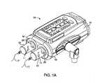
図1Aを参照すると、自動または動力式流体インジェクタなどの流体インジェクタ10(以下、「インジェクタ10」と呼ぶ)が示されており、これは1つ以上のシリンジ12と接続し、かつシリンジを駆動し、シリンジは造影剤、生理食塩水、または任意の所望の医療用流体などの医療用流体Fで満たされていてもよい。インジェクタ10は、医療手順の間に使用され、シリンジ12のプランジャ26をピストン要素で駆動することによって患者の体内に医療用流体を注入してもよい。インジェクタ10は、マルチシリンジインジェクタであってもよく、幾つかのシリンジ12は、並列または他の関係で配向されてもよく、インジェクタ10に関連するそれぞれのリニアアクチュエータまたはピストン要素上のプランジャ26によって別々に作動されてもよい。インジェクタ10は、少なくとも1つのシリンジ12から1つ以上の流体を独立して送達するように構成されてもよい。 Referring to FIG. 1A, a fluid injector 10 (hereinafter referred to as “
インジェクタ10は、プラスチックまたは金属などの適切な構造材料から形成されたハウジング14内に収容してもよい。ハウジング14は、所望の用途に応じて様々な形状および大きさであってよい。例えば、インジェクタ10は、床に配置されるように構成された自立構造であってもよく、または適切なテーブルまたは支持フレーム上に配置するためのより小さい設計であってもよい。インジェクタ10は、少なくとも1つのシリンジ12をそれぞれのピストン要素に接続するための少なくとも1つのシリンジポート16を含む。以下に説明するように、幾つかの実施形態では、シリンジ12は、インジェクタ10のシリンジポート16内に、シリンジ12を解放可能に自己配向させるように構成された少なくとも1つの係合部材を含む。本明細書で説明するように、少なくとも1つの係合部材は、インジェクタ10のシリンジポート16に設けられたロック機構を動作可能と係合させるように構成され、シリンジ12のシリンジポート16からの排出を含み、シリンジ12のインジェクタ10への装着およびインジェクタ10からの取り出しを容易にする。少なくとも1つの係合部材およびロック機構は、少なくとも1つのシリンジ12をインジェクタ10に可逆的に接続するための接続インターフェースを共に画定する。 The
流体通路セット17は、少なくとも1つのシリンジ12から血管アクセス部位で患者に挿入されたカテーテル(図示せず)、針、または、他の流体送達接続部に医療用流体Fを送達するために、少なくとも1つのシリンジ12の内の少なくとも1つのシリンジと流体接続されてもよい。少なくとも1つのシリンジ12からの流体の流れは、流体制御モジュール(図示せず)によって調整されてもよい。流体制御モジュールは、様々なピストン、弁および流れ調整構造が、注射速度、持続時間、総注射量および造影剤と生理食塩水の比などのユーザが選択した注射パラメータに基づいて、患者への生理食塩水および造影剤などの医療用流体の送達を調整するように操作する。本明細書に記載された、少なくとも1つのシリンジの流体インジェクタとの自己配向装填および解放可能な保持のための、少なくとも1つのシリンジおよび少なくとも1つのシリンジインターフェースでの使用のために改変されてもよい適切なフロントローディング流体インジェクタが、全体の引用により組み入れられるReillyらの米国特許第5,383,858号に開示される。改変されてもよい他の関連する多流体送達システムは、Lazzaroらの米国特許第7,553,294号明細書、Cowanらの米国特許第7,666,169号明細書、国際特許出願第PCT/US2012/037491号パンフレット(国際公開第2012/155035号パンフレットとして公開)、およびRileyらの米国特許出願公開第2014/0027009号明細書に記載され、それらの全ては、本開示の譲受人に譲渡されており、その開示は引用により本明細書に組み込まれる。 The fluid passage set 17 is at least for delivering the medical fluid F from at least one
インジェクタ10の一般的な構造および機能を説明したため、少なくとも1つのシリンジ12の構造を、以下により詳細に説明する。図1Bを参照すると、シリンジ12は、一般に、ガラス、金属、または適切な医学グレードのプラスチックから形成された略円筒形のシリンジバレル18を有する。バレル18は、バレル18の中心を通って延在する長手方向軸15の長さに沿って間に延在する略周側壁19を備えた近位端部20および遠位端部24を有する。バレル18は、透明または半透明の材料で作られ、シリンジバレル18(図1Aに示す)内の流体Fの存在を確認するための少なくとも1つの流体確認部材11を含んでいてもよい。流体通路17に接続するためのノズル22は、バレル18の遠位端部24から延在している。バレル18は、外面21と、内部に医療用流体を収納するように構成された内部容積25を画定する内面23とを有する。バレル18の近位端部20は、バレル18を通って摺動可能なプランジャ26で封止されてもよい。プランジャ26は、バレル18の側壁19の内面に対して、可逆的に前進する際に液密封止を形成する。プランジャ26は、インジェクタ10のピストンと係合するように構成された剛性内部要素28を有していてもよい。プランジャ26は、剛性内部要素28の少なくとも一部の上に配置されたエラストマーカバー29をさらに含んでいてもよい。エラストマーカバー29は、可逆的に前進する際にバレル18の内面23と係合し、バレル18の側壁19に対して液密封止を提供するように構成される。 Having described the general structure and function of the
引き続き図1Bを参照すると、シリンジ12の近位端部20は、(図1Aに示される)インジェクタ10の少なくとも1つのシリンジポート16内に挿入されるように寸法決めされ適合される。幾つかの実施形態では、シリンジ12の近位端部20は、インジェクタ10のシリンジポート16に取り外し可能に挿入されるように構成された挿入部30を画定する一方、シリンジ12の残りの部分はシリンジポート16の外側に留まる。以下で詳細に説明するように、特定の実施形態では、シリンジ12の近位端部20は、シリンジポート16内のシリンジ12を開放可能に保持するために、インジェクタ10のシリンジポート16内の対応するロック機構と共にロック係合を形成するように構成された少なくとも1つの係合部材32を含む。保持フランジ41を備えた1つ以上の係合部材32を有するシリンジ12と、インジェクタ10のロック機構35(図2Bに示す)との組み合わせは、シリンジ12のインジェクタ10への装填およびインジェクタ10からの取り外しのための接続インターフェースを画定する。 Continuing with reference to FIG. 1B, the
特定の実施形態によると、ドリップフランジ36は、長手方向軸15に対してシリンジバレル18の外面21から半径方向外向きに延在してもよい。ドリップフランジ36は、バレル18の外周の少なくとも一部の周りに延在してもよい。一実施形態では、ドリップフランジ36は、1つ以上の係合部材32に対して長手方向軸15に沿って遠位に、かつ保持フランジ41の遠位に配置される。ドリップフランジ36は、ノズル22から滴下する流体がインジェクタ10のシリンジポート16に入るのを防止するように構成されてもよい。このようにして、ドリップフランジ36は、シリンジポート16に入り、接続インターフェース100を詰まらせる、または妨げる、あるいはインジェクタ10の機構または電子機器を汚染する可能性がある流体の量を低減するのに役立つ。幾つかの実施形態では、ドリップフランジ36は、シリンジ12の挿入部30がインジェクタ10のシリンジポート16および/またはロック機構に、どの程度まで挿入され得るかを定める挿入停止面を画定してもよい。ドリップフランジ36は、バレル18と一体的に形成されてもよく、または例えば、摩擦嵌合および/または接着剤、溶接を使用して、または成形によって、バレル18の外面21に取り付けられる、または固定されてもよい。他の実施形態では、ドリップフランジ36は、エッチング、レーザ切断、または機械加工によってバレル18の外面21に形成されてもよい。 According to certain embodiments, the
他の実施形態では、挿入停止面は、存在する場合には、ドリップフランジ36に対してバレル18の近位端部20の近くに配置された保持フランジ41によって画定されてもよい。保持フランジ41は、長手方向軸15に対してシリンジバレル18の外面21から半径方向外向きに延在してもよい。保持フランジ41は、バレル18の外周の少なくとも一部の周りに延在してもよく、単一の連続フランジあるいは1つ以上の不連続または断続的なセグメントであってもよい。一実施形態では、保持フランジ41は、係合部材32に対して長手方向軸15に沿って遠位に配置される。保持フランジ41は、バレル18と一体的に形成されてもよく、または例えば、摩擦嵌合および/または接着剤、溶接を使用して、または成形によって、バレル18の外面21に取り付けられる、または固定されてもよい。他の実施形態では、保持フランジ41は、エッチング、レーザ切断、または機械加工によってバレル18の外面21に形成されてもよい。保持フランジ41は、1つ以上の係合部材32から遠位方向にバレル18の長さに沿う任意の場所にあってもよい。幾つかの実施形態では、保持フランジ41は、1つ以上の係合部材32上に直接または隣接して形成されてもよい。保持フランジ41は、バレル18の内径を一定に保ちながら、側壁19の厚さを増加させることによって、またはバレル18の内径を大きくし、かつ側壁19の厚さを維持、減少または増加させることによっても形成されてもよい。この例示的な実施形態では、保持フランジ41の遠位表面は、シリンジポート16の1つ以上の保持要素78の1つ以上の保持面78R(図2Bに示す)と接触する保持面41R(図2Aに示す)を形成する。保持フランジ41の少なくとも一部分、例えば保持フランジ41の近位面は、長手方向軸15に向かってまたは遠ざかるように半径方向に先細るまたは面取りされてもよい。 In other embodiments, the insertion stop surface, if present, may be defined by a holding
図2A~図2Bを特に参照すると、インジェクタ10(図1に示す)の少なくとも1つのシリンジポート16から少なくとも1つのシリンジ12を装填し、かつ取り外す/排出するための接続インターフェース100が、一実施形態により示される。シリンジ12およびインジェクタ10は、シリンジ12に設けられた少なくとも1つの係合部材32およびインジェクタ10のシリンジポート16(図1に示す)に設けられた対応するロック機構35を有する接続インターフェース100を含む。一実施形態では、少なくとも1つの係合部材32は、シリンジバレル18の近位端部20に設けられる。例えば、少なくとも1つの係合部材32は、シリンジバレル18の終端部27から近位方向に軸方向に突出していてもよい。少なくとも1つの係合部材32は、バレル18と一体的にかつ一体的に形成されてもよく、または例えば、摩擦嵌合および/または接着剤を使用して、または溶接によって、バレル18の終端部27に取り付けられる、または固定されてもよい。他の実施形態では、少なくとも1つの係合部材32は、エッチング、レーザ切断、機械加工、または成形によってバレル18の終端部27に形成されてもよい。幾つかの実施形態では、1つ以上の係合部材32は、ロック機構の少なくとも一部と協働して、シリンジポート16に対してシリンジ12を自己配向させ、シリンジ12をシリンジポート16および/またはロック機構35に向けるために、シリンジの物理的な整列あるいは他のユーザまたは技術者による努力なしに、シリンジ12はシリンジポート16に解放可能にロックされてもよい。 With particular reference to FIGS. 2A-2B, one embodiment is a
図2A~図2Bに示す実施形態では、少なくとも1つの係合部材32は、図1Bおよび図2A~図2Bに破線で示すシリンジバレル18の終端部27から近位方向に軸方向に突出する1つ以上の突起として形成される。少なくとも1つの係合部材32は、少なくとも1つの係合部材32がバレル18の外面21および内面23(図1Bに示す)と略連続するように、シリンジバレル18の側壁19と同じ半径方向の厚さを有していてもよい。他の実施形態では、少なくとも1つの係合部材32は、バレル18の外面21に対して半径方向外向きまたは半径方向内向きに突出していてもよい。さらに、または代替的に、少なくとも1つの係合部材32は、バレル18の内面23に対して半径方向外向きまたは半径方向内向きに突出していてもよい。他の実施形態では、少なくとも1つの係合部材32は、例えば、内面23および外面21の終端部が少なくとも1つの係合部材32の近位端部と略同じ高さであるように、側壁19の内部に配置されてもよい。特定の実施形態では、複数の係合部材32は、本明細書で詳述するように、バレル18の円周の周りに波形状または正弦波形状で配置されてもよい。3つ以上の係合部材32が設けられる実施形態では、係合部材32は、バレル18の外周の周りに均等に離間していてもよい。例えば、6つの係合部材32を有する実施形態では、各係合部材32は、隣接する係合部材32から60度離される。x個の係合部材32を有する他の実施形態では、各係合部材32は、隣接する係合部材32から360/x度離されており、xは1~360の整数である。他の実施形態では、少なくとも1つの係合部材32は、バレル18の外周の周りに不等角度間隔を有していてもよい。例えば、1つ以上の係合部材32は、バレル18の円周の60度を超えるかまたは60度未満であってもよい角度A(図1Bに示す)を定めてもよい。少なくとも1つの係合部材32が不等角度間隔を有する幾つかの実施形態では、様々な係合部材32の間隔および配置は、例えば製造業者、ロット番号、製造年月日、容量、圧力最小/最大、様々な医療用流体との適合性などのシリンジおよび/またはシリンジの内容に関する情報を符号化するために使用されてもよい。幾つかの実施形態では、係合部材32の各々は、シリンジバレル18の終端部27から近位方向に等距離で突出していてもよい。他の実施形態では、1つ以上の係合部材32は、残りの係合部材32よりも長くても短くてもよい。各係合部材32は、略剛性があり、シリンジ12のシリンジポート16への挿入およびシリンジポート16からの取り外しの間、半径方向または周方向に偏向することがない。各係合部材32は、連続して途切れない、または係合部材32を共に画定する複数の別個の要素で構成されていてもよい。 In the embodiments shown in FIGS. 2A-2B, at least one engaging
図1Bを再び参照すると、各係合部材32は、長手方向軸15に沿って、係合部材32の近位端部37からシリンジ12の終端部27に向けて遠位方向に延在する一対のテーパ面39A~39Bを備えた略尖った近位端部37を有していてもよい。近位端部37は、尖ったまたは丸い点を有してもよい。テーパ面39A~39Bの少なくとも1つは、長手方向軸15の方向に対して角度Bで軸方向および/または周方向に角度をなしていてもよい(図1Bに示す)。長手方向軸15に対する少なくとも1つのテーパ面39A~39Bの軸方向/周方向の先細りは、シリンジバレル18の遠位端部24から近位端部20に向かう方向に、円筒形の平面投影図において少なくとも1つのテーパ面39A~39Bの傾斜角として画定されてもよい。テーパ面39A~39Bは、長手方向軸15に対して同じまたは異なる角度で角度をなしていてもよい。幾つかの実施形態では、テーパ面39A~39Bは、直線状、曲線状、またはそれらの組み合わせであってもよい。他の実施形態では、テーパ面39A~39Bの内の片方の断面は、テーパ面39A~39Bの他方のものと同じであっても異なっていてもよい。例えば、テーパ面39A~39Bの内の片方は、長手方向軸15の方向に対して角度をなしていてもよく、一方、テーパ面39A~39Bの他方は、長手方向軸15の方向と平行であってもよい。少なくとも2つの係合部材32が互いに隣接して配置される実施形態では、1つの係合部材32のテーパ面39Aは、隣接する各係合部材32のテーパ面39Bに移行してもよい。 Referring again to FIG. 1B, each engaging
図2A~図2Bは、少なくとも1つの係合部材32の1つの非限定的な実施形態を示しているが、様々な他の形状も考えられる(例えば、他の非限定的な実施形態の図4A~図4Qを参照)。例えば、少なくとも1つの係合部材32は、ほぼ円形、三角形、正方形、長方形、または他の多角形の形状を有してもよい。本明細書で説明するように、各実施形態において、少なくとも1つの係合部材32は、保持フランジ41と組み合わせて、シリンジポート16内のシリンジ12を開放可能に保持するために、インジェクタ10のシリンジポート16内の対応するロック機構35と共に自己配向式ロック係合を形成するように構成される。係合部材32の各実施形態について、さらに、使用される係合部材32の数は、本開示の範囲内にある限り、変更されてもよいと考えられる。例えば、図1Bに示すシリンジ12では、1つの係合部材32のみがシリンジ12の終端部27に設けられることが企図されている。単一の係合部材32を使用してもよいが、シリンジ12の実施形態は、少なくとも2つの係合部材32を有してもよい。偶数個の係合部材32を有する幾つかの実施形態では、係合部材32は互いに正反対に位置してもよい。他の実施形態では、係合部材32は、互いに隣接して設けられる。係合部材32は、適切な大きさであってもよく、任意に、異なる円周寸法であってもよい。少なくとも1つの係合部材32の適切な形状の様々な非限定的な実施形態が、図4A~図4Qを参照して本明細書で説明される。 2A-2B show one non-limiting embodiment of at least one engaging
図2A~図2Bを引き続き参照すると、インジェクタ10のシリンジポート16は、シリンジ12の少なくとも1つの係合部材32と保持フランジ41とを動作可能と係合するように構成されたロック機構35を有する。ロック機構35は、シリンジ12の近位端部20を収納するように構成された中央開口部71を備えたハウジング70を含む。ハウジング70は、インジェクタ10のハウジング14の一部として形成されてもよく(図1Aに示される)、ハウジング14に取り付けられて、既存のインジェクタを、現在説明されているロック機構35を含むように改造してもよい。ガイドリング48がハウジング70に対して固定され、ガイドリング48がハウジング70に対して回転したり、長手方向に移動したりすることはない。一実施形態では、ガイドリング48は、本体72の外周から半径方向外向きに延在する1つ以上のタブ74(図2Aに示す)を有する本体72を有する。ガイドリング48の本体72は、連続的な環状形状を有してもよく、または2つ以上の別個のセグメントから形成されてもよい。ハウジング70内に設置される場合、1つ以上のタブ74は、ハウジング70の内側壁73上の対応する1つ以上の溝76と係合し(図2Aに示される)、ガイドリング48の回転/長手方向移動を防止する。他の実施形態では、ガイドリング48は、クリップ、留め具、またはスナップフィット装置などの他の機械的固定装置によってハウジング70に固定されてもよい。さらなる実施形態では、ガイドリング48は、ハウジング70と溶接、接着または成形されてもよい。ハウジング70に設置される場合、ガイドリング48の中心軸は、ハウジング70の中心軸と同軸である。 With reference to FIGS. 2A-2B, the
図2Aを参照すると、ガイドリング48は、対応する1つ以上の偏向可能な保持要素78を摺動可能に収納するように構成された1つ以上の第1の凹部60を有する。1つ以上の第1の凹部60は、ガイドリング48の本体72の周りに均等に離間していてもよい。一実施形態では、1つ以上の第1の凹部60は、ガイドリング48の内周から外周に延在している。例えば、ガイドリング48が4つの第1の凹部60を有する実施形態では、各第1の凹部60は、両側に隣接する第1の凹部60から90度離れて分離されてもよい。他の実施形態では、1つ以上の第1の凹部60は、ガイドリング48の本体72の周りに不均等に離間していてもよい。ガイドリング48上の第1の凹部60の数は、偏向可能な保持要素78の数に対応してもよい。第1の凹部60は、偏向可能な保持要素78の移動を案内するために、偏向可能な保持要素78の底面のピンまたは溝とそれぞれ接触するように、底面に溝またはピンを含んでいてもよい。各第1の凹部60の側縁は、シリンジ12の挿入部30がガイドリング48に挿入され、かつガイドリング48から排出されるときに、偏向可能な保持要素78の移動を半径方向に案内する半径方向移動経路を画定する。シリンジ12がロック機構35内に挿入される場合に、ガイドリング48の上面の少なくとも一部は、シリンジ12の近位方向への移動を制限する停止面59を画定してもよい。一実施形態では、シリンジ12の保持フランジ41が停止面59と係合して、シリンジ12の近位方向への移動を制限する。 Referring to FIG. 2A, the
引き続き図2Aを参照すると、ロック機構35は、ガイドリング48に対して半径方向に摺動するように構成された1つ以上の偏向可能な保持要素78をさらに含む。さらに詳述するように、1つ以上の偏向可能な保持要素78の各々は、両方とも互いに固定されたガイドリング48およびハウジング70に対して半径方向に摺動可能である。ばねのような少なくとも1つの第1の弾性部材102(図2Aに示す)は、一端で、1つ以上の偏向可能な保持要素78の少なくとも一部に接続され、他端でハウジング70の少なくとも一部に接続される。少なくとも1つの第1の弾性部材102は、1つ以上の偏向可能な保持要素78を、少なくとも1つの偏向可能な保持要素78上のロックリップ80がガイドリング48の停止面59上に配置される第1の位置(図2B参照)に付勢し、保持ギャップ81を画定する(図2B参照)。一実施形態では、シリンジ12をシリンジポート16に挿入することによって、シリンジ12の保持フランジ41が少なくとも1つの偏向可能な保持要素78のロックリップ80と係合して、偏向可能な保持要素78を半径方向外向きに偏向させ、シリンジ12がロック機構35に挿入されるのを可能にする。ロックリップ80は、シリンジ12の近位方向への移動が、少なくとも1つの偏向可能な保持要素78をシリンジ12に対して半径方向外向きに付勢する半径方向向きの成分を有する力をもたらすように、長手方向軸15に対して半径方向に角度をなしていてもよい。代替的には、保持フランジ41の近位面は、シリンジ12の近位方向への移動が、少なくとも1つの偏向可能な保持要素78をシリンジ12に対して半径方向外向きに付勢する半径方向向きの成分を有する力をもたらすように、長手方向軸15に対して半径方向に傾斜すなわち面取りされていてもよい。シリンジ12の保持フランジ41がロックリップ80を放出した後、少なくとも1つの偏向可能な保持要素78は、少なくとも1つの第1の弾性部材102の付勢下で初期の第1の位置に復帰する。本明細書に説明するように、シリンジ12をロック機構35から解放するために、シリンジ12の1つ以上の係合部材32がロック/解放リング84と係合し、回転すると、1つ以上の偏向可能な保持要素78を第2の位置すなわち開位置に移動し、シリンジ12をロック機構35から排出させることができる。 Continuing with reference to FIG. 2A, the
引き続き図2Aを参照すると、ロック機構35は、概ね環状の形状を有するロック/解放リング84をさらに含んでいてもよい。ロック/解放リング84は、少なくとも1つの係合部材32の1つ以上と係合し、シリンジポート16内のシリンジ12の選択的な位置決めを制御し、1つ以上の偏向可能な保持要素78の、シリンジ12の保持フランジ41との選択的ロック係合を可能にするように構成される。ロック/解放リング84は、少なくとも1つの係合部材32を少なくとも1つのシリンジ係合部材83と係合することによって、シリンジ12のその長手方向軸15を中心にした回転に伴い、ハウジング70に対して回転可能である。 Continuing with reference to FIG. 2A, the
特定の実施形態では、ロック/解放リング84は、ロック/解放リング84の内周の周りに延在する1つ以上のシリンジ係合部材83を有する。1つ以上のシリンジ係合部材83は、シリンジ12上の少なくとも1つの係合部材32の内の1つ以上の係合部材の形状と相補的な形状を有する。一実施形態では、1つ以上のシリンジ係合部材83は、シリンジ12の終端部27における少なくとも1つの係合部材32の形状に対応する形状にされる。例えば、様々な実施形態において、1つ以上のシリンジ係合部材83は、波形状または正弦波形状を有してもよい。1つ以上のシリンジ係合部材83は、シリンジ12がシリンジポート16に挿入されるか、シリンジポート16から引き抜かれる際に、テーパ面39A~39Bがスライドすることができる相互作用面85Aおよび85Bを有する。相互作用面85Aおよび85Bは、シリンジ12に面する遠位方向に先細り、尖ったまたは丸い点になっている。相互作用面85Aおよび85Bの少なくとも1つは、長手方向軸15の方向に対して軸方向に角度をなしていてもよい。長手方向軸15に対する少なくとも1つの相互作用面85A~85Bの軸方向の先細りは、シリンジ12がシリンジポート16内に挿入される場合に、シリンジ12の近位端部20に向かう方向に、円筒形の平面投影図において相互作用面85A~85Bの傾斜角として画定されてもよい。相互作用面85A~85Bは、長手方向軸15に対して同じまたは異なる角度で角度をなしていてもよい。幾つかの実施形態では、相互作用面85A~85Bは、直線状、曲線状、階段状であってもよいが略直線状/曲線状表面を画定する、またはそれらの組み合わせであってもよい。他の実施形態では、相互作用面85A~85Bの内の片方の断面は、相互作用面85A~85Bの他方のものと同じであっても異なっていてもよい。例えば、相互作用面85A~85Bの内の片方は、長手方向軸15の方向に対して角度をなしていてもよく、一方、相互作用面85A~85Bの他方は、長手方向軸15の方向と平行であってもよい。 In certain embodiments, the lock /
2つ以上の係合部材32がシリンジ12に設けられる実施形態では、各係合部材32がそれぞれのシリンジ係合部材83と係合するように、1つ以上のシリンジ係合部材83は、対応するすなわち相補的な形状および角度間隔を有するように成形されてもよい。他の実施形態では、少なくとも1つの係合部材32は、1つ以上のシリンジ係合部材83の数に対して複数の係合部材32を有してもよい。シリンジ12がロック機構35内にロックされる場合のような第1の位置では、各係合部材32は、対応するシリンジ係合部材83と整列される。シリンジ12がロック機構35から取り外される場合のような第2の位置では、各係合部材32は、対応するシリンジ係合部材83からずらして回転させながら移動される。 In an embodiment in which two or more
引き続き図2Aを参照すると、ロック/解放リング84は、偏向可能な保持要素78の各々の動きを案内するためのガイドスロット86をさらに含む。各ガイドスロット86は、ロック/解放リング84の上面88の外周に配置されている。各ガイドスロット86は、対応する偏向可能な保持要素78が、シリンジ12がロック機構35内でロックされる第1の位置と、シリンジ12がロック機構35からロック解除される第2の位置との間で案内されるガイドトラック90を有する。一実施形態では、各偏向可能な保持要素78の少なくとも一部は、偏向可能な保持要素78の底部から近位に突出するピンまたは他の係合部材などによって、ガイドトラック90と係合する。第1の位置では、各偏向可能な保持要素78は、第1の端部92でガイドトラック90と係合し、各偏向可能な保持要素78はその最も半径方向内側の位置にある。この位置では、シリンジ12の保持フランジ41は、1つ以上の偏向可能な保持要素78のロックリップ80によって保持されており、シリンジ12をその長手方向軸15に対して回転させ、かつ解放機構と係合することなくして、シリンジ12をロック機構35から取り外すことはできない。シリンジ12がその長手方向軸15の周りで回転すると、ロック/解放リング84が回転し、各偏向可能な保持要素78は、ガイドトラック90に沿って半径方向外向きに、各偏向可能な保持要素78がその最も半径方向外向きの位置にある第2の端部94に向かって案内される。この位置で、保持フランジ41が各偏向可能な保持要素78のロックリップ80を放出するように、シリンジ12を遠位方向に排出または付勢することによって、シリンジ12はロック機構35から取り外される。シリンジ12がロック機構35から解放されると、ロック/解放リング84は、ハウジング70のベース98に固定されていてもよい第2の弾性部材96の復元作用下で、同時に第1の位置に回転される。特定の実施形態では、第2の弾性部材96の復元作用下で、ロック/解放リング84を第1の位置に戻して回転させると、シリンジ12に、シリンジポート16からシリンジ12を排出または付勢する横方向の力が与えられる。 Continuing with reference to FIG. 2A, the lock /
シリンジ12をシリンジポート16内に挿入するために、シリンジ12の長手方向軸15は、シリンジポート16の長手方向軸とほぼ整列している。最初に、シリンジ12は、シリンジ12をシリンジポート16に対して長手方向軸15の周りに回転させながら配向することなく、中央開口部71の上部に挿入することができる。シリンジ12の挿入部30は、シリンジポート16の開口部71に挿入される。シリンジ保持フランジ41は、少なくとも1つの偏向可能な保持要素78のロックリップ80と接触するように近位方向に付勢され、保持要素が半径方向外向きに偏向されて、シリンジ12がハウジング70内に挿入することが可能になる。シリンジポート16に対するシリンジ12の近位への移動が継続すると、1つ以上の偏向可能な保持要素78が第1の凹部60内で半径方向外向きに第2の位置に偏向され、ここで中央開口部のサイズが増大して、保持フランジ41が通過することが可能になる。係合部材32の山部がシリンジポート16上のシリンジ係合部材83の谷部に収納される、および/または保持フランジ41がガイドリング48上の停止面59と係合するまで、各係合部材32の1つ以上のテーパ面39A~39Bが対応する相互作用面85A~85Bと接触して、シリンジ12を回転させながら自己配向させるように、シリンジ12は、シリンジポート16内に近位に前進される。少なくとも1つの第1の弾性部材102の復元作用下で、1つ以上の偏向可能な保持要素78は、第2の位置から第1の位置へと半径方向に付勢され、1つ以上の偏向可能な保持要素78のロックリップ80が、停止面59とロックリップ80の底面との間の保持フランジ41上に配置されてもよい。ドリップフランジ36が保持フランジ41として機能する特定の実施形態では、1つ以上の偏向可能な保持要素78を保持フランジ41の上に配置して、ドリップフランジ36を停止面59とロックリップ80の底面との間に保持してもよい。この動作によって、シリンジ12がシリンジポート16内にロックされていることをユーザに示すために、可聴フィードバックおよび/または触覚フィードバックが提供されてもよい。 To insert the
シリンジ12をシリンジポート16からロック解除して解放するために、シリンジ12は、例えば時計回りまたは反時計回りの方向に、その長手方向軸15の周りを回転してもよい。シリンジ12の回転により、少なくとも1つの係合部材32が1つ以上のシリンジ係合部材83に対して移動し、ロック/解放リング84を回転させて1つ以上の偏向可能な保持要素78を半径方向に第2の位置に移動させ、保持フランジ41をロックリップ80から解放する。シリンジ係合部材83の相互作用テーパ面85A~85Bに沿ったテーパ面39A~39Bの移動によって、シリンジ12に付与される軸方向の力成分により、シリンジ12の継続的な回転は、1つ以上のシリンジ係合部材83に対する、つまり軸方向に整列しない、少なくとも1つの係合部材32のさらなる移動をもたらす。このようにして、シリンジ12の終端部27は、1つ以上のシリンジ係合部材83の相互作用テーパ面85A~85Bに沿うテーパ面39A~39Bの移動によって、遠位方向に付勢/放出される。本明細書で説明するように、シリンジ12が回転すると、ロック/解放リング84も回転し、各偏向可能な保持要素78は、ガイドトラック90に沿って半径方向外向きに、各偏向可能な保持要素78がその最も半径方向外向きの位置にある第2の端部94に向かって案内される。この位置で、テーパ面39A~39Bと、シリンジ係合部材83の相互作用テーパ面85A~85Bとの相互作用によって生じる軸方向の力のために、シリンジバレル18および保持リング41は、1つ以上の偏向可能な保持要素78に対して遠位に付勢され、これはさらに、1つ以上の偏向可能な保持要素78を、第1の位置から第2の位置に半径方向外向きに付勢する。使用者が遠位への力を加えずに、1つ以上の偏向可能な保持要素78のロックリップ80がシリンジ12の保持フランジ41を放出する場合、シリンジ12は、シリンジポート16から排出され、付勢され、または飛び出してもよい。ロック解除するための十分な回転のこの触覚的および物理的確認、ならびに軸方向の引っ張りを必要としないなど、さらなる使用者の労力を必要としないシリンジ12の排出または飛び出しは、従来技術のシリンジおよびシリンジインジェクタポートに対して著しい改良である。排出されたシリンジ12は、シリンジ12を遠位方向に引き出すことによって、ロック機構35から容易に取り外すことができる。保持リング41がロックリップ80を越えて遠位に移動し、および/または少なくとも1つの係合部材32が1つ以上のシリンジ係合部材83から分離するなど、シリンジ12がロック機構35から排出されると、1つ以上の偏向可能な保持要素78がそれらの第1の初期位置に戻され、ロック機構35が新しいシリンジ12の挿入の準備ができているように、第2の弾性部材96の復元作用下で、ロック/解放リング84が第1の位置に回転される。 To unlock and release the
ロック機構35の動作をさらに説明するために、係合されるとシリンジポート16内にシリンジ12を保持するために協働するシリンジ12およびシリンジポート16の保持面は、シリンジ12の保持フランジ41の1つ以上の表面およびシリンジポート16の偏向可能な保持要素78の1つ以上の表面である。シリンジ12は、最初は概ね軸方向に整列され、シリンジポート16の開口部71に挿入される。一旦部分的に挿入されると、設置のためにシリンジ12およびシリンジポート16を自己配向させるか、自動的に回転移動を強制して自己配向させるために協働するシリンジ12およびシリンジポート16のガイド面は、シリンジ12上の係合部材32の1つ以上の表面39A~39Bおよびシリンジポート16上のシリンジ係合部材83の1つ以上のテーパガイド面85A~85Bである。シリンジ12の設置のためにシリンジポート16を押し開くために協働するシリンジ12およびシリンジポート16の開口面は、シリンジ12上の保持フランジ41の1つ以上の底面およびシリンジポート16上のロックリップ80の1つ以上のテーパ面である。機械的な遊びまたは公差を吸収するために協働するシリンジ12およびシリンジポート16の締め付け面は、シリンジポート16の外側ハウジングすなわち封止に対して押し、保持フランジ41をシリンジポート16上のロックリップ80に対して付勢するシリンジ12上のドリップフランジ36上の1つ以上の表面を含んでいてもよい。また、シリンジ12を前方に付勢するための締め付け力は、ロック/解放リング84を回転させながら付勢し、シリンジ12上の係合部材32の1つ以上の表面39A~39Bと、シリンジ係合部材83の1つ以上のテーパガイド面85A~85Bとの相互作用から遠位への力をもたらす第2の弾性部材96、あるいはロック/解放リング84を遠位方向に付勢し、十分な長さのシリンジ12と協働する場合、保持フランジ41をロックリップ80に対して付勢する第3の弾性部材(図示せず)などの弾性部材によって提供されてもよい。シリンジ12をシリンジポート16から分離するまたは取り外すために協働するシリンジ12およびシリンジポート16の分離面は、シリンジ12の係合部材32の表面およびシリンジポート16のシリンジ係合部材83の表面である。遠位方向の力を生成するために協働して、シリンジ12のシリンジポート16からの放出を促すシリンジ12およびシリンジポート16の排出面は、シリンジ12の係合部材32の1つ以上の表面39Aおよび39Bならびにシリンジポート16上のシリンジ係合部材83の1つ以上のテーパガイド面85A~85Bである。シリンジ12上にルアーコネクタがねじ止めされると、協働して回転を防止するシリンジ12およびシリンジポート16の回転停止面は、シリンジ12の係合部材32上の1つ以上のテーパ面39Aおよび39Bと、シリンジポート16上のシリンジ係合部材83の1つ以上のテーパガイド面85A~85Bであり、同時にシリンジ12の保持フランジ41の1つ以上の面とシリンジポート16の偏向可能な保持要素78の1つ以上の保持面との間および/またはドリップフランジ36の底面とシリンジポート16の外側ハウジングすなわち封止との間の摩擦力を防ぐ。 To further illustrate the operation of the
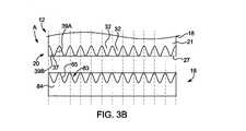
図3A~図3Dは、シリンジ12の近位端部20における少なくとも1つの係合部材32と、シリンジ12の近位端部20を収納するための対応するシリンジポート16のシリンジ係合部材83との様々な実施形態の円筒形の平面投影図を示す。図3Aを参照すると、シリンジ12の近位端部20における少なくとも1つの係合部材32とロック/解放リング84のシリンジ係合部材83との間の境界面の円筒形の平面投影図が、シリンジ12をシリンジポート16に嵌合するために回転させながら整列された向きで示される。この例示的な実施形態では、シリンジ12上の少なくとも1つの係合部材32およびシリンジポート16上の対応するシリンジ係合部材83は、シリンジ12上およびロック/解放リング84上の交互の山部および谷部を有するシリンジ12の近位端部20で、概ね正弦波状の突起として構成される。シリンジ12上の係合部材32は、シリンジ12の終端部27から軸方向に離れて突出している。シリンジ12とシリンジ係合部材83とが最初に整列していない場合、矢印Aの方向の下方すなわち遠位への力は、シリンジ12上のテーパ面39A~39Bと対応するシリンジ係合部材83上のテーパガイド面85A~85Bとの摺動相互作用をもたらす。そのような摺動相互作用は、シリンジ係合部材83上の対応するテーパガイド面85A-85Bと整列させる正しい回転位置に、シリンジ12を回転して自己配向させ、シリンジポート16へのシリンジ12の正しい向きの取り付けをもたらす。 3A-3D show at least one engaging
図3Bは、シリンジ12の別の実施形態の別の円筒形の平面投影図である。本実施形態では、係合部材32は、シリンジバレル18の側壁19の厚さに部分的にのみ延在している。幾つかの実施形態では、係合部材32は、シリンジバレル18の外面21上に配置されてもよい。係合部材32の近位端部37は、シリンジバレル18の終端部27で終端してもよい。他の実施形態では、近位端部37は、例えば図3Aに示すように、シリンジバレル18の終端部27に対して近位方向に延在していてもよい。このようにして、シリンジバレル18をより剛性な軸方向整列のためにより強く製造することができる。さらに、近位端部20の内面は、シリンジプランジャ26の取り付けを容易にするための滑らかな連続面として形成されてもよい。同様に、ロック/解放リング84は、ロック/解放リング84の半径方向の厚さの一部のみを通って延在するシリンジ係合部材83を有してもよい。図3Cは、係合部材32がシリンジバレル18の側壁19の厚さの一部のみを通って延在し、シリンジバレル18の内側表面上に配置されている別の実施形態の別の円筒形の平面投影図である。シリンジ係合部材83の対応する相補的装置がロック/解放リング84上に存在する。本実施形態では、ロック/解放リング84の内側の材料は、シリンジバレル18の近位端部20を強化し、より高圧の注射で使用してもよい。幾つかの実施形態では、係合部材32は、シリンジバレル18の側壁19の少なくとも一部を通って、シリンジ12の外面21または内面23から延在していてもよい。他の実施形態では、係合部材32は、シリンジバレル18の側壁19内に適切な断面のボイドまたはポケットを形成することによって形成される。ボイドまたはポケットは、ロック/解放リング84上に存在する相補的なシリンジ係合部材83と相互作用するように構成されてもよい。 FIG. 3B is another cylindrical plan projection of another embodiment of the
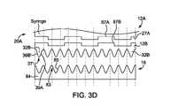
図3Dは、本明細書に記載のシリンジポート16および/またはロック機構35と直接的に接触することができない代替のシリンジ12Aと共に使用するためのアダプタ12Bの実施形態の円筒形の平面投影図である。一実施形態によると、アダプタ12Bは、代替のシリンジ12Aの終端部27Aの少なくとも一部に取り外し可能または取り外し不能に取り付けられる、あるいはシリンジポート16内のロック機構35に挿入されて、ロック機構35を代替シリンジ12Aと相互作用させる、例えば環状、円弧状、または他の形状で構成されてもよい。アダプタ12Bは、本明細書に記載のシリンジ12の少なくとも1つの係合部材32と同様の1つ以上の係合部材32Bを有していてもよい。各係合部材32Bは、シリンジポート16の対応するシリンジ係合部材83と相互作用するように構成されてもよい。アダプタ12Bの遠位は、シリンジ12Aの対応する特徴部または突起部と嵌合する特徴部または突起部を有してもよい。例えば、アダプタ12Bは、シリンジ12A上の対応するロック部材87A内に収納されるように構成されたロック部材87B、またはシリンジ12Aがアダプタ12Bと嵌合し、シリンジポート16および/またはロック機構35内に保持されることを可能にする他のロック特徴部を有してもよい。 FIG. 3D is a cylindrical plan projection of an embodiment of the
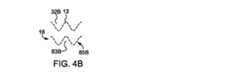
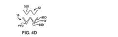
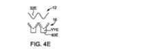
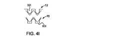
図4A~図4Qは、シリンジ12上の少なくとも1つの係合部材32の一部の様々な実施形態、およびシリンジポート16内のロック/解放リング84上のシリンジ係合部材83の対応する実施形態の円筒形の平面投影図の一部を示す。図4A~図4Qは、シリンジ12の実施形態での使用に適した係合部材32(32A~32Qとして示す)および/またはシリンジ係合部材83(83A~83Qとして示す)および/またはシリンジポート16内のロック/解放リング84の代替の実施形態の形状を表示する。図4Aは、図3Aを参照して本明細書で説明した実施形態の係合部材32および83のセグメントを円筒形の平面投影図で示している。図4Bは、様々な実施形態のために、シリンジ12上の係合部材32Bの近似面およびシリンジポート16上の対応するシリンジ係合部材83Bを点線で示す。図4Cは、シリンジ係合部材83Cの谷部YYCが係合部材32Cの表面に比べて拡張されている実施形態を示しており、一方図4Dは、シリンジ係合部材83Dの表面が1つ以上の直線セグメントを含み、係合部材32Dを収納するための谷部YYDを画定する。図4Eは、83Eの谷部YYEの少なくとも一部が、例えば任意の破片または他の外部材料からの干渉を低減するために、略長方形の断面を有し、係合部材34Eと依然として相互作用することができる実施形態を示す。図4Fは、シリンジ係合部材83Fが、シリンジ12上の係合部材32Fに選択的に接触してもよい1つ以上の遠位突起部83FBを備えた平らな底面83FAを有する実施形態を示す。本実施形態では、シリンジ12の係合部材32Fの底部セグメントは、シリンジ係合部材83Fの谷部YYFに接触して、シリンジ12の回転の前の幾つかの回転スロップ、ギャップまたは公差がテーパ面32Fと1つ以上の遠位突起部83FBとの間の接触、およびロック/解放リング84Fの対応する回転をもたらす。図4Gに示す実施形態では、係合部材32Gの底部セグメントは、シリンジ係合部材83Gの谷部分YYGに接触しない。むしろ、係合部材32Gは、図4Fの動作と同様の動作で突起部83GBの少なくとも一部と係合する。図4Hは、係合部材32Hとシリンジ係合部材83Hの両方が少なくとも1つの区分化された直線面を有し、シリンジ係合部材83Hの山部がシリンジ12上の係合部材32Hの谷部に嵌合するが、好ましくは完全には塞がない実施形態を示す。図4Iは、係合部材32Iおよびシリンジ係合部材83Iの両方が、各部材の傾斜面間で相互作用が確実に起こるように、それぞれの谷部に完全に嵌合するには幅が大きすぎる別の実施形態を示す。 4A-4Q show various embodiments of a portion of at least one engaging
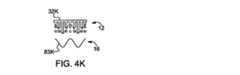
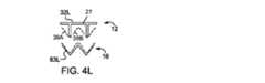
図4Jは、長手方向軸15に変化する長さの複数の別個のセグメントを有する係合部材32Jを示し、セグメントの遠位端部または端部は、本明細書に説明するシリンジ係合部材83J内に嵌合するのに必要な概ね正弦波状断面またはその他の断面を画定する。図4Kは、シリンジ12がシリンジポート16内に挿入された場合に、セグメントの一部が半径方向には撓むが周方向には曲がらない場合があるように、共通の長さの複数の別個のセグメントを有する係合部材32Kを示す。本実施形態では、係合部材32Kがシリンジ係合部材83Kと相互作用する場合、本明細書で説明するように、重なり合う突起部はシリンジ係合部材83Kに対して半径方向に撓むが、係合部材32K上の重ならない突起部は対応するシリンジ係合部材83Kと係合する。別の実施形態では、シリンジ係合部材83は、シリンジ12上の係合部材32の輪郭と一致するように周方向に移動して共に群を成し、分離動作を作動させる回転力を伝達するばね付勢ボールまたはフィンガーを含んでいてもよい。図4Lは、シリンジ係合部材83Lと相互作用するように構成された長手方向軸15と略平行な突起部を含む棒状構造を有する係合部材32Lを有する実施形態を示す。係合部材32Lは、各係合部材32Lの基端遠位端部から遠位方向にシリンジバレル18(図1Bに示す)の終端部27に向かって延在する仮想テーパ面39A~39Bを有する。図4Mは、長手方向軸15(図2Bに示す)に対して先細るように傾斜した突起部を備えた棒状構造を有する係合部材32Mの実施形態を示す。幾つかの実施形態では、係合部材32Mは、シリンジ係合部材83Mと相互作用するのに十分な剛性があってもよい。係合部材32の他の実施形態は、シリンジ終端部27と突起部の中間部との間に補強支持部を含んでいてもよい。あるいは、係合部材32Mは、シリンジポート16からのシリンジ12の排出中に、分離するために回転すると撓んで、追加のばね力を提供してもよい。 FIG. 4J shows an engaging
図4Nは、係合部材32Nおよびシリンジ係合部材83Nが、略傾斜した山部を形成するために接触する略線形のテーパ面を有する鋸歯パターンを画定する実施形態を示す。係合部材32Nは、シリンジ係合部材83Nに対して等しいまたは等しくないピーク間高さまたはテーパ角を有してもよく、またはその逆であってもよい。図4Oは、シリンジ12上の係合部材32Oの周波数が、シリンジポート16内のロック/解放リング84上のシリンジ係合部材83Oの周波数よりも、例えば2倍大きい実施形態を示す。他の実施形態では、シリンジ12上の係合部材32Oの周波数は、シリンジポート16上のシリンジ係合部材83Oの周波数に対して整数倍であってもよい。他の実施形態では、シリンジ12上の係合部材32Oの周波数は、シリンジポート16上のシリンジ係合部材83Oの周波数よりも小さくてよく、例えば、周波数の整数比であってもよい。図4Pは、1つ以上のシリンジ係合部材83Pが存在しない実施形態を示す。図示されていないが、シリンジ12上の1つ以上の係合部材32Pも存在しなくてもよい。あるいは、1つ以上の係合部材32Pが存在しなくてもよい。図4Qは、係合部材32Qが基点で丸みを帯び、最先端点で角度を有し、相補的なシリンジ係合部材83Qが略尖った山部を有する実施形態を示す。少なくとも1つの係合部材32の形状の様々な非制限的実施形態が図4A~図4Qに示されているが、このような形状は、本開示の他の実施形態により、シリンジ係合部材83に、または係合部材32とシリンジ係合部材83の両方に使用されてもよいことを理解されたい。さらに、様々な係合部材の形状の組み合わせは、シリンジ12、ロック/解放リング84、またはその両方に使用してもよい。さらに、シリンジ12上の係合部材32は、本明細書に記載されるように、図4A~図4Qに示される係合部材の様々な実施形態と均等物の様々な組み合わせを含んでいてもよい。さらに、ロック/解放リング84上のシリンジ係合部材83は、本明細書に記載されるように、図4A~図4Qに示されるシリンジ係合部材の様々な実施形態と均等物の様々な組み合わせを含んでいてもよい。 FIG. 4N shows an embodiment in which an engaging
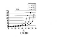
図5Aは、シリンジ12をシリンジポート16に挿入する間、少なくとも1つの係合部材32上のテーパ面39A~39Bと、少なくとも1つのシリンジ係合部材83上のテーパガイド面85A~85Bとの間に存在する力の一般化された自由体図である。シリンジ12上の少なくとも1つの係合部材32は、使用者の手によって提供される遠位方向の力Pのために、シリンジポート16上の少なくとも1つのシリンジ係合部材83と相互作用する。図5Bに示すように、この一般化された相互作用に関する静的力解析を実行することにより、表面間の様々な摩擦係数μに対する2組のテーパ面の相互作用の軸方向から測定した角度Aの関数として挿入力の推定値が得られる。幾つかの実施形態では、シリンジ12はポリエチレンテレフタレート(PET)材料から製造され、ロック/解放リング84はDELRIN(商標)などのポリオキシメチレン(POM)材料から製造されてもよい。他のDELRIN(商標)表面上のDELRIN(商標)の摩擦係数μは約0.4である。様々な他の表面の摩擦係数を測定し、適切に計算に使用することができる。この値を用いると、妥当な挿入挙動を可能にするための角度Aの実際的な限界は、シリンジ12の長手方向軸15の方向に対して測定し、約60~65度である。角度Aの他の実際的な限界は、少なくとも1つの係合部材32および少なくとも1つのシリンジ係合部材83のそれぞれのテーパ面39A~39Bおよび85A~85Bの最適な角度範囲を決定するために、他の摩擦係数について決定されてもよい。摩擦係数が0.6の場合、50~55°未満の角度を使用してもよい。 FIG. 5A shows between the
図6Aは、シリンジ12の少なくとも1つの係合部材32に対する3つの異なる正弦曲線設計の重なりを示す。パターンAAは、0.2インチのピーク間高さと直径1.9インチのシリンジの周りに16サイクルの繰り返しを有する。バレル壁の厚さは、シリンジの直径に比べて比較的小さい。パターンBBは、0.2インチのピーク間高さと、直径1.9インチのシリンジの周りに6サイクルの繰り返しを有する。パターンCCは、0.4インチのピーク間高さと、直径1.9インチのシリンジの周りに8サイクルの繰り返しを有する。図6Bは、直径1.9インチのシリンジの円周の周りの長手方向軸15(図5Aに示す)に対する角度方向を示す。角度は、Angle=90-Abs(ArcTan(-(H*N/D)*Sin(N*θ)))の式で表されてもよく、ここでHは、パターンのピーク間高さであり、Dはパターンの直径であり、Nはバレル周りの繰り返しのサイクル数であり、角度は、図5Aに示す長手方向軸15の向きに平行な方向から測定される。この計算から、パターンAAおよびCCは、角度が65°を上回る小さい部分を有し、したがって、挿入するのが困難であり得る。 FIG. 6A shows the overlap of three different sinusoidal designs for at least one engaging
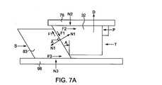
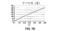
図7Aは、シリンジ12をシリンジポート16へ解放排出するときに存在する、少なくとも1つの係合部材32上のテーパ面39A~39Bと少なくとも1つのシリンジ係合部材83上のテーパガイド面85A~85Bとの間にかかる力の一般化された自由体図を示す。シリンジ12上の力は、例えば、係合部材83に対する係合部材32の法線力N1および摩擦力F1、保持フランジ41上の偏向可能な保持要素78の法線力N2および摩擦力F2ならびに使用者がシリンジを回転させるために加える回転力T、さらにドリップフランジ36によって与えられるシリンジを近位に付勢する任意の力Dである。シリンジ係合部材83は、ベース98上を摺動する際の法線力N3および摩擦力F3と、第2の弾性部材96からの復元力Sとを有する。図7Bに示すように、静的解析は、係合部材32とシリンジ係合部材83との間の界面における滑りに角度Aが必要であることを示している。摩擦係数μ1が0.4の場合、最小角度は約20度である。したがって、20度よりも大きな角度に対しては滑りが生じ、偏向可能な保持要素78が保持フランジ41を放出するのに十分な移動の際に、シリンジはシリンジポート16から排出される。図7Cは、第2の弾性部材96の復元力Sが増加するときの、シリンジ12を回転させる回転力Tの比率を示す。比は、角度が大きくなると同時に比較的一定であるが、大きな角度では比が劇的に増加する。幾つかの例では、30度以上で約60度未満の角度を使用してもよい。 FIG. 7A shows
別の実施形態では、シリンジバレル18の周囲の少なくとも1つの係合部材32の1つ以上の存在または欠如を用いて、シリンジ12またはシリンジ内容物に関する情報を伝えるまたは符号化してもよい(例えば、予め充填されたシリンジで)。例えば、シリンジ12の周囲の特定の部位における少なくとも1つの係合部材32の1つ以上の存在または欠如は、様々な電子手段、例えば光センサ、機械的スイッチ、容量センサ、およびインジェクタ10のシリンジポート16内の他の手段によって検知することができる。少なくとも1つの係合部材32の1つ以上の存在または欠如によって表されてもよい符号化された情報の例として、単一の符号は係合部材32の欠如、2つ以上の係合部材32の欠如は、例えば係合部材32間の異なる空間に複数の符号を提供してもよい。 In another embodiment, the presence or absence of one or more of at least one engaging
図8Aを参照すると、それ用の取り付け部材を含む連結器130は、シリンジバレル18とは別個に、かつシリンジバレルに取り付け可能であるように製造することができる。連結器130は、例えば、本明細書に記載の少なくとも1つの係合部材32を有するシリンジ12を収納し、かつ少なくとも1つの係合部材32を収納するように構成されないロック機構を備えたシリンジポートを有する流体インジェクタと共に使用するためにシリンジ12を適合させるように構成することができる。例えば、連結器130は、米国特許第5,383,858号明細書または米国特許第6,652,489号明細書に記載の流体インジェクタまたは他の流体インジェクタと共に使用するためにシリンジ12を適合させることができる。幾つかの実施形態では、連結器130は、インジェクタに取り外し可能に接続可能である。他の実施形態では、連結器130は、流体インジェクタのロック機構に挿入され、保持されてもよい。連結器130はまた、インジェクタへの連結器の取り付けとは独立して、シリンジ12に取り外し可能に接続されるか、または取り付けられてもよい。 With reference to FIG. 8A, the
図8Aを参照すると、連結器130は、本明細書に記載の実施形態による少なくとも1つの係合部材32を有するシリンジ12を、収納するように構成された第1部分132と、本明細書に記載の実施形態による少なくとも1つの係合部材32を有するシリンジ12を、収納するように構成されないシリンジポートを有するインジェクタに装填するように構成される第2部分134とを有する。第1部分132は、第2部分134と直接接続され、一体的に形成されてもよい。幾つかの実施形態では、様々な第2部分(図9A~図9Bに示される)が第1部分132と共に使用されてもよいように、第1部分132は、第2部分134に解放可能に接続されてもよい。引き続き図8Aを参照すると、第1部分132は、本明細書に記載のロック機構35を有する。様々な実施形態において、連結器130の第1部分132は、本明細書で説明するように、対応する少なくとも1つの係合部材32を有するシリンジ12を解放可能に収納するように構成されてもよい。図9A~図9Bを参照すると、連結器130の第2部分134は、本明細書に記載の少なくとも1つの係合部材32を有するシリンジ12を収納することができないインジェクタと接続するように構成された接続インターフェースを有してもよい。図9Aは、米国特許第5,383,858号明細書に記載のインジェクタの係合機構と共に使用するように構成された第2部分134を示し、図9Bは、米国特許第6,652,489号明細書に記載のインジェクタの係合機構と共に使用するように構成された第2部分134を示す。第2部分134は、シリンジの近位端部の係合機構の構成に基づいて、本明細書に明示的に記載されていない様々な他のインジェクタと接触するように構成されてもよい。幾つかの実施形態では、連結器130は、連結器130をインジェクタのロック機構と係脱するための別個の機構を有してもよい。 Referring to FIG. 8A, the
図8Bを参照すると、アダプタ230は、本明細書に記載の実施形態の1つにより、ロック機構35を有するインジェクタに取り外し可能に挿入するための本明細書に記載の1つ以上の係合部材32を有さないシリンジSを収納するように構成されてもよい。様々な実施形態では、アダプタ230は、インジェクタに後で取り付けるためにシリンジSに接続するように構成されてもよい。例えば、アダプタ230は、対応していないシリンジSに解放可能にまたは永久的に接続されてもよい。このようなアダプタ230は、本明細書で説明する実施形態による少なくとも1つの係合部材32を有する接続インターフェースを有していてもよい。アダプタ230は、本明細書に記載のロック機構35を有するインジェクタと解放可能に接続可能に構成されてもよい。インジェクタに接続する前に、アダプタ230とシリンジSを接続してもよく、アダプタ230は、シリンジSをアダプタ230に接続する前にインジェクタに接続してもよい。アダプタ230およびシリンジSは、使用後にインジェクタから取り外してもよく、アダプタ230はシリンジSと共に配置されるか、または使用済みシリンジSから取り外され、その後別のシリンジSと使用するために保管されてもよい。 Referring to FIG. 8B, the
一実施形態では、アダプタ230の第1部分232は、本明細書に記載のロック機構35のいずれとも使用に対応していないシリンジSを、永久的にまたは解放可能に収納するように構成されてもよい。幾つかの実施形態では、シリンジSは、米国特許第5,383,858号明細書または米国特許第6,652,489号明細書に記載のシリンジ、または他の任意のシリンジタイプであってもよい。アダプタ230は、対応していないシリンジSが、本明細書に記載のロック機構35に係合して保持されることを可能にする。幾つかの実施形態では、アダプタ230は、アダプタ230がインジェクタ10のロック機構35に接続されたままで、シリンジSを係脱するための別個の機構を有してもよい。第1部分232はまた、他のシリンジS、例えば手持ち式シリンジまたは異なる保持機構または特徴部を有し、それらがロック機構35と係合し保持されることを可能にするシリンジ、を把持または保持するためのクレードルまたはスリーブであってもよい。アダプタ230の第2部分234は、本明細書に記載の実施形態により、少なくとも1つの係合部材32を有してもよい。幾つかの実施形態では、少なくとも1つの係合部材32は、図1B~図4Qを参照して本明細書で説明される構成を有してもよい。アダプタ230の第2部分234は、本明細書に記載のロック機構35を有するインジェクタと解放可能に接続可能に構成されてもよい。このようにして、様々な対応していないシリンジSを、本明細書に記載のロック機構35を有するインジェクタと共に使用してもよい。様々な実施形態において、アダプタ230は、高圧を必要とする注射手順で使用するための圧力ジャケット(図示せず)をインジェクタに接続するように構成されてもよい。例えば、圧力ジャケットを有するアダプタ230は、インジェクタと解放可能に接続可能に構成されてもよい。このようなアダプタ230は、本明細書に記載された実施形態による少なくとも1つの係合部材32を有する接続インターフェースを有するか、または、対応していないシリンジをインジェクタと共に使用することを可能にする接続インターフェースを有してもよい。アダプタ230は、本明細書に記載されたロック機構35を有するインジェクタに解放可能に、永久的に、または半永久的に接続され、代替の保持機構を有するシリンジSをインジェクタと共に使用することを可能にするように構成されてもよい。一旦インジェクタに接続されると、シリンジSは、アダプタ230またはそれに取り付けられた圧力ジャケットに装填され、その近位端部または遠位端部で保持されてもよい。 In one embodiment, the
様々な実施形態において、アダプタ230は、図3Dを参照して本明細書で説明されるように、本明細書に記載されたインジェクタ10への後続の取り付けに必要な特徴部の全てではないが幾つかを有するシリンジを接続するように構成されてもよい。アダプタ230は、自身ではインジェクタポート16と嵌合または完全には機能することができないシリンジが、ロック機構35と嵌合および少なくとも保持機能を実行することを可能にする。アダプタ230を回転させることによって、シリンジおよびアダプタは、シリンジポートから解放されてもよい。同様に、挿入時に、アダプタ230をシリンジとの係合のために近位に押してもよい。本明細書で論じるように、アダプタは、インジェクタポート16およびシリンジ12Aと接触する図3Dに示すアダプタ12Bのようなリングとすることができる。オプションとして、アダプタ230は、操作者がアダプタの1つ以上の態様を移動させて、アダプタをシリンジポートから解放し、および/またはシリンジに力を直接加えたり、移動させたりする必要なくアダプタからシリンジを解放することができるレバー、ハンドルまたはリングなどの追加の表面(図示せず)を含むことができる。 In various embodiments, the
図2Aを参照すると、シリンジ12からインジェクタ10(図1Aに示す)に情報を送信するシステムが設けられていてもよい。一実施形態では、シリンジ12に、例えば、1つ以上の係合部材32上に1つ以上の符号化装置49を設けてもよい。他の実施形態では、1つ以上の符号化装置49は、外面21(図1Bに示す)、内面23(図1Bに示す)、シリンジ12の近位端部20の側壁19(図1Bに示す)の少なくとも一部分内、またはプランジャ26上に設けられてもよい。幾つかの実施形態では、符号化装置49は、バーコードなどの光学的に読み取り可能な部材であってもよく、他の実施形態では、符号化装置49は、RFIDタグ、近距離通信装置、または他の任意の適切な符号化装置であってもよい。複数の符号化装置49は、シリンジ12および/またはプランジャ26の内周または外周に設けられてもよい。符号化装置49を読み取るために、少なくとも1つのセンサ51(図2Aに示す)をシリンジポート16上に設けてもよい。幾つかの実施形態では、少なくとも1つのセンサ51は、少なくとも1つの偏向可能な保持要素78上に設けられてもよい。符号化装置49で符号化することができる情報の例には、限定されないが、シリンジ12の寸法、シリンジ12の容量、シリンジ12の内容(予め充填されたシリンジの場合)、ロット番号、日付およびツールキャビティ番号などの製造情報、推奨される造影剤の流量および圧力、および/または充填/注射シーケンスを含む。一実施形態では、1つ以上の係合部材32の存在または欠如が符号化装置としての役割を果たしてもよい。例えば、1つの係合部材32の欠如は、第1の符号を表してもよい。2つ以上の隣接する係合部材32の欠如は、第2の符号を表してもよい。2つ以上の隣接しない係合部材32の欠如は、第3の符号を表してもよい。係合部材32の存在/欠如の他の様々な組み合わせは、様々な他の符号を表してもよい。個々の係合部材32の存在または欠如は、機械的スイッチ、電気材料センサ、光学的、視覚的、またはセンシング技術分野で知られている他の手段により、インジェクタによって判断することができる。このシリンジ符号化情報は、操作者との通信のため、ならびにインジェクタを正確にプログラミングおよび制御する際の後続の使用のために、インジェクタ制御装置に伝達される。 Referring to FIG. 2A, a system may be provided to transmit information from the
幾つかの実施形態では、図2Aおよび図3Aに示すロック機構35のベース98のようなインジェクタ10(図1Aに示す)の少なくとも一部は、シリンジ12の近位端部20の内部容積25の少なくとも一部分に突出する内部支持リング(図示せず)を有してもよい。そのような支持リングは、内部容積25の少なくとも一部の中に取り外し可能に伸長可能であってもよい。シリンジ12がロック機構35内に挿入される場合、支持リングは、シリンジ12の1つ以上の係合部材32および/または内側壁23(図1Bに示される)の少なくとも一部に、半径方向および軸方向の支持を提供してもよい。図2Aに示すような少なくとも1つのセンサ51がシリンジポート16上に設けられる実施形態では、支持リングは、少なくとも1つの符号化装置49の存在または欠如を検出するための対照面を提供してもよい。例えば、支持リングは、少なくとも1つの符号化装置49の検出を容易にするために、シリンジ12の半透明または透明な側壁19に対して対照的な不透明な表面を提供してもよい。 In some embodiments, at least a portion of the injector 10 (shown in FIG. 1A), such as the
本開示は、現在最も実用的かつ好ましい実施形態であると現在考えられているものに基づいて説明するために詳細に記載されているが、そのような詳細はその目的のためのみであり、本開示は、開示された実施形態に限定されず、逆に、修正および同等の仕組みをカバーすることが意図されている。例えば、本開示は、可能な限り、任意の実施形態の1つ以上の特徴を任意の他の実施形態の1つ以上の特徴と組み合わせることができることを意図することを理解されたい。 The present disclosure has been described in detail for illustration based on what is currently considered to be the most practical and preferred embodiment, but such details are for that purpose only and are described in this publication. Disclosure is not limited to the disclosed embodiments and, conversely, is intended to cover modifications and equivalent mechanisms. For example, it should be understood that the present disclosure is intended to be able to combine one or more features of any other embodiment with one or more features of any other embodiment wherever possible.
10 流体インジェクタ
11 流体確認部材
12 シリンジ
12A 代替シリンジ
12B アダプタ
14 ハウジング
15 長手方向軸
16 シリンジポート、インジェクタポート
17 流体通路
18 シリンジバレル
19 側壁
20 近位端部
21 外面
22 ノズル
23 内側壁、内面
24 遠位端部
25 内部容積
26 プランジャ
27 終端部
27A 終端部
28 剛性内部要素
29 エラストマーカバー
30 挿入部
32 係合部材
32B 係合部材
32C 係合部材
32D 係合部材
32F 係合部材、テーパ面
32G 係合部材
32H 係合部材
32I 係合部材
32J 係合部材
32K 係合部材
32L 係合部材
32M 係合部材
32N 係合部材
32O 係合部材
32P 係合部材
32Q 係合部材
34E 係合部材
35 ロック機構
36 ドリップフランジ
37 近位端部
39A テーパ面
39B テーパ面
41 保持フランジ、保持リング
41R 保持面
48 ガイドリング
49 符号化装置
51 センサ
59 停止面
60 凹部
70 ハウジング
71 中央開口部
72 本体
73 内側壁
74 タブ
76 溝
78 保持要素
78R 保持面
80 ロックリップ
81 保持ギャップ
83 シリンジ係合部材
83B シリンジ係合部材
83C シリンジ係合部材
83D シリンジ係合部材
83F シリンジ係合部材
83FA 底面
83FB 遠位突起部
83G シリンジ係合部材
83GB 突起部
83H シリンジ係合部材
83I シリンジ係合部材
83J シリンジ係合部材
83K シリンジ係合部材
83L シリンジ係合部材
83M シリンジ係合部材
83N シリンジ係合部材
83O シリンジ係合部材
83P シリンジ係合部材
83Q シリンジ係合部材
84 解放リング
84F 解放リング
85A 相互作用テーパ面、テーパガイド面
85B 相互作用テーパ面、テーパガイド面
86 ガイドスロット
87A ロック部材
87B ロック部材
88 上面
90 ガイドトラック
92 端部
94 端部
96 弾性部材
98 ベース
100 接続インターフェース
102 弾性部材
130 連結器
132 第1部分
134 第2部分
230 アダプタ
232 第1部分
234 第2部分10 fluid injector
11 Fluid confirmation member
12 Syringe
12A alternative syringe
12B adapter
14 Housing
15 Longitudinal axis
16 Syringe port, injector port
17 Fluid passage
18 Syringe barrel
19 Side wall
20 Proximal end
21 exterior
22 Nozzle
23 Inner side wall, inner surface
24 Distal end
25 internal volume
26 Plunger
27 Termination
27A Termination
28 Rigid internal elements
29 Elastomer cover
30 Insert
32 Engagement member
32B engaging member
32C engaging member
32D engaging member
32F engaging member, tapered surface
32G engaging member
32H engaging member
32I Engagement member
32J engaging member
32K engagement member
32L engaging member
32M engaging member
32N engaging member
32O engaging member
32P engaging member
32Q engaging member
34E Engagement member
35 Lock mechanism
36 drip flange
37 Proximal end
39A Tapered surface
39B Tapered surface
41 Retaining flange, retaining ring
41R holding surface
48 guide ring
49 Encoding device
51 Sensor
59 Stop surface
60 recess
70 housing
71 Central opening
72 body
73 Inner wall
74 tabs
76 groove
78 Retention element
78R Holding surface
80 rock lip
81 Retention gap
83 Syringe engagement member
83B Syringe engagement member
83C Syringe Engagement Member
83D Syringe Engagement Member
83F Syringe engagement member
83FA bottom
83FB Distal protrusion
83G Syringe Engagement Member
83GB protrusion
83H Syringe engagement member
83I Syringe engagement member
83J Syringe engagement member
83K Syringe Engagement Member
83L syringe engagement member
83M Syringe Engagement Member
83N Syringe engagement member
83O Syringe engagement member
83P Syringe engagement member
83Q Syringe engagement member
84 Release ring
84F release ring
85A Interaction taper surface, taper guide surface
85B Interaction taper surface, taper guide surface
86 guide slot
87A Lock member
87B Lock member
88 Top surface
90 guide track
92 end
94 end
96 Elastic member
98 base
100 connection interface
102 Elastic member
130 coupler
132
134
230 adapter
232
234
Claims (13)
Translated fromJapanese前記少なくとも1つのシリンジを前記少なくとも1つのシリンジポート内に固定するために、前記少なくとも1つのシリンジポートに設けられたロック機構であって、前記少なくとも1つのシリンジを前記少なくとも1つのシリンジポート内に解放可能に配置およびロックするために、前記少なくとも1つのシリンジの近位端部に近い外周の少なくとも一部の周りの保持フランジおよび前記シリンジの前記近位端部における複数の係合部材を係合するように構成されるロック機構と
を備え、
前記複数の係合部材の各々のテーパが、前記シリンジの回転時に前記シリンジを軸方向に排出する、
流体インジェクタ。An injector housing defining at least one syringe port for accommodating at least one syringe,
A locking mechanism provided in the at least one syringe port to secure the at least one syringe in the at least one syringe port, releasing the at least one syringe into the at least one syringe port. Engage a holding flange around at least a portion of the outer circumference near the proximal end of the at least one syringe and a plurality of engaging members at the proximal end of the syringe to allow for placement and locking. Equipped with a locking mechanism configured to
Each taper of the plurality of engaging members ejects the syringe axially as the syringe rotates.
Fluid injector.
前記少なくとも1つのシリンジが前記少なくとも1つのシリンジポートに挿入される場合に、前記複数の係合部材の1つ以上と係合するための相補形状を有している1つ以上のシリンジ係合部材を備えているロック/解放リングであって、前記少なくとも1つのシリンジの長手方向軸の周りの回転に伴って、前記ハウジングに対して回転可能である、ロック/解放リング
をさらに備え、
前記ロック/解放リングの回転は、前記ロック機構を前記シリンジ上の前記フランジから分離させ、前記少なくとも1つのシリンジが前記少なくとも1つのシリンジポートから軸方向に排出することを可能にさせる、請求項1に記載の流体インジェクタ。The lock mechanism
One or more syringe engagement members having a complementary shape for engaging with one or more of the plurality of engagement members when the at least one syringe is inserted into the at least one syringe port. A lock / release ring comprising a lock / release ring that is rotatable with respect to the housing as the at least one syringe rotates about a longitudinal axis.
The rotation of the lock / release ring separates the lock mechanism from the flange on the syringe and allows the at least one syringe to be axially ejected from the at least one syringe port. The fluid injector described in.
シリンジが前記流体インジェクタのシリンジポートに挿入される場合に、複数の係合部材の1つ以上と係合するための相補形状を有している1つ以上のシリンジ係合部材を備えているロック/解放リングであって、前記シリンジの長手方向軸の周りの回転に伴って、前記流体インジェクタのハウジングに対して回転可能であるロック/解放リングと、
前記ロック機構内で前記シリンジを解放可能に保持するために前記少なくとも1つのシリンジの近位端部に近い外周の少なくとも一部の周りの保持フランジと相互作用するように構成された少なくとも1つの偏向可能な保持要素であって、前記少なくとも1つのシリンジの近位方向への移動が、前記少なくとも1つの偏向可能な保持要素の半径方向外向きの移動をもたらすように、前記長手方向軸に対して角度をなしているロックリップを有している、少なくとも1つの偏向可能な保持要素と、
一端で、前記少なくとも1つの偏向可能な保持要素の少なくとも一部に接続され、第2の端部で前記流体インジェクタの少なくとも一部に接続される少なくとも1つの弾性部材であって、前記少なくとも1つの偏向可能な保持要素を半径方向内向きに付勢する少なくとも1つの弾性部材とを含むロック機構。A syringe lock mechanism for fluid injectors,
A lock comprising one or more syringe engaging members having a complementary shape for engaging with one or more of the plurality of engaging members when the syringe is inserted into the syringe port of the fluid injector. A lock / release ring that is rotatable with respect to the housing of the fluid injector as it rotates about the longitudinal axis of the syringe.
At least one deflection configured to interact with a holding flange around at least a portion of the outer circumference near the proximal end of the at least one syringe to hold the syringe releasably within the locking mechanism. A possible holding element with respect to the longitudinal axis such that proximal movement of the at least one syringe results in radial outward movement of the at least one deflectable holding element. With at least one deflectable retaining element, which has an angled lock lip,
At least one elastic member at one end connected to at least a portion of the at least one deflectable retaining element and at a second end connected to at least a portion of the fluid injector, said at least one. A locking mechanism that includes at least one elastic member that urges the deflectable holding element inward in the radial direction.
Applications Claiming Priority (2)
| Application Number | Priority Date | Filing Date | Title |
|---|---|---|---|
| US14/526,395 | 2014-10-28 | ||
| US14/526,395US9199033B1 (en) | 2014-10-28 | 2014-10-28 | Self-orienting syringe and syringe interface |
Related Parent Applications (1)
| Application Number | Title | Priority Date | Filing Date |
|---|---|---|---|
| JP2017522967ADivisionJP6728155B2 (en) | 2014-10-28 | 2015-10-28 | Self-orienting syringe and syringe interface |
Publications (2)
| Publication Number | Publication Date |
|---|---|
| JP2020168420A JP2020168420A (en) | 2020-10-15 |
| JP7053724B2true JP7053724B2 (en) | 2022-04-12 |
Family
ID=54542532
Family Applications (2)
| Application Number | Title | Priority Date | Filing Date |
|---|---|---|---|
| JP2017522967AActiveJP6728155B2 (en) | 2014-10-28 | 2015-10-28 | Self-orienting syringe and syringe interface |
| JP2020112840AActiveJP7053724B2 (en) | 2014-10-28 | 2020-06-30 | Self-oriented syringe and syringe interface |
Family Applications Before (1)
| Application Number | Title | Priority Date | Filing Date |
|---|---|---|---|
| JP2017522967AActiveJP6728155B2 (en) | 2014-10-28 | 2015-10-28 | Self-orienting syringe and syringe interface |
Country Status (16)
| Country | Link |
|---|---|
| US (3) | US9199033B1 (en) |
| EP (2) | EP3848068A1 (en) |
| JP (2) | JP6728155B2 (en) |
| KR (1) | KR20170074969A (en) |
| CN (1) | CN106999654B (en) |
| AR (1) | AR102458A1 (en) |
| BR (1) | BR112017008404A2 (en) |
| CA (1) | CA2965814C (en) |
| DK (1) | DK3212255T3 (en) |
| ES (1) | ES2860700T3 (en) |
| IL (1) | IL251553A0 (en) |
| MX (1) | MX2017005238A (en) |
| RU (1) | RU2017118364A (en) |
| TW (1) | TWI627978B (en) |
| WO (1) | WO2016069688A1 (en) |
| ZA (1) | ZA201703640B (en) |
Families Citing this family (68)
| Publication number | Priority date | Publication date | Assignee | Title |
|---|---|---|---|---|
| USD1031029S1 (en) | 2003-11-25 | 2024-06-11 | Bayer Healthcare Llc | Syringe plunger |
| US7666169B2 (en) | 2003-11-25 | 2010-02-23 | Medrad, Inc. | Syringe and syringe plungers for use with medical injectors |
| US8926569B2 (en) | 2006-03-15 | 2015-01-06 | Bayer Medical Care Inc. | Plunger covers and plungers for use in syringes and methods of fabricating plunger covers and plungers for use in syringes |
| USD847985S1 (en) | 2007-03-14 | 2019-05-07 | Bayer Healthcare Llc | Syringe plunger cover |
| USD942005S1 (en) | 2007-03-14 | 2022-01-25 | Bayer Healthcare Llc | Orange syringe plunger cover |
| US9174003B2 (en) | 2012-09-28 | 2015-11-03 | Bayer Medical Care Inc. | Quick release plunger |
| AU2015231396B2 (en) | 2014-03-19 | 2018-12-06 | Bayer Healthcare Llc | System for syringe engagement to an injector |
| ES2873963T3 (en) | 2014-04-25 | 2021-11-04 | Bayer Healthcare Llc | Rolling Diaphragm Syringe |
| WO2015191560A1 (en) | 2014-06-10 | 2015-12-17 | Bayer Medical Care Inc. | Syringe with indicator float |
| CN107073197A (en) | 2014-06-10 | 2017-08-18 | 拜耳医药保健有限公司 | The antidrip guard of syringe |
| WO2016069714A1 (en)* | 2014-10-28 | 2016-05-06 | Bayer Healthcare Llc | Self-orienting pressure jacket and pressure jacket-to-injector interface |
| US9199033B1 (en)* | 2014-10-28 | 2015-12-01 | Bayer Healthcare Llc | Self-orienting syringe and syringe interface |
| WO2016134275A1 (en) | 2015-02-20 | 2016-08-25 | Bayer Healthcare Llc | Contrast imaging agent with dissolved gas-evolving fluid |
| US10933190B2 (en) | 2015-04-24 | 2021-03-02 | Bayer Healthcare Llc | Syringe with rolling diaphragm |
| DK3341048T3 (en) | 2015-08-28 | 2023-08-21 | Bayer Healthcare Llc | SYSTEM AND METHOD FOR VERIFYING INJECTION FLUID FILLING AND IMAGE RECOGNITION OF POWER INJECTOR SYSTEM TRAITS |
| CA3003321C (en) | 2015-10-28 | 2023-09-26 | Bayer Healthcare Llc | System and method for fluid injector engagement with a pressure jacket and syringe cap |
| US9480797B1 (en) | 2015-10-28 | 2016-11-01 | Bayer Healthcare Llc | System and method for syringe plunger engagement with an injector |
| EP3380157B1 (en) | 2015-11-25 | 2021-07-21 | Bayer Healthcare LLC | Syringe tip with fluid wicking drip flanges |
| US10898638B2 (en) | 2016-03-03 | 2021-01-26 | Bayer Healthcare Llc | System and method for improved fluid delivery in multi-fluid injector systems |
| EP3481462B1 (en) | 2016-07-06 | 2021-03-24 | Bayer Healthcare LLC | Contrast heating system with in-line contrast warmer |
| US10532166B2 (en) | 2016-07-08 | 2020-01-14 | Bayer Heatlhcare Llc | System and method for identifying a fill volume of a fluid chamber |
| WO2018017447A1 (en) | 2016-07-18 | 2018-01-25 | Bayer Healthcare Llc | Fluid injector and patient set therefor |
| AR109649A1 (en) | 2016-09-16 | 2019-01-09 | Bayer Healthcare Llc | PRESSURE SHIRT WITH SYRINGE RETAINING ELEMENT |
| US11999084B2 (en) | 2016-09-27 | 2024-06-04 | Bayer Healthcare Llc | Rotary injection molding apparatus for producing plastic components such as syringes |
| CA3040484A1 (en) | 2016-10-17 | 2018-04-26 | Bayer Healthcare Llc | Fluid injector with syringe engagement mechanism |
| CN109843355B (en) | 2016-10-17 | 2022-03-25 | 拜耳医药保健有限公司 | Fluid Syringe with Syringe Engagement Mechanism |
| US12263326B2 (en) | 2016-11-14 | 2025-04-01 | Bayer Healthcare Llc | Methods and systems for verifying the contents of a syringe used for medical fluid delivery |
| HUE063479T2 (en) | 2017-01-06 | 2024-01-28 | Bayer Healthcare Llc | Syringe plunger with dynamic seal |
| PL3589337T3 (en) | 2017-02-28 | 2024-03-11 | Bayer Healthcare Llc | Identification tag reader system |
| CN106823070B (en)* | 2017-03-21 | 2023-03-07 | 深圳安特医疗股份有限公司 | Syringe identification device, high-pressure injector and control method thereof |
| JP7493337B2 (en) | 2017-08-31 | 2024-05-31 | バイエル・ヘルスケア・エルエルシー | Method for dynamic pressure control in a fluid injector system - Patents.com |
| AU2018326386B2 (en) | 2017-08-31 | 2024-03-28 | Bayer Healthcare Llc | Fluid injector system volume compensation system and method |
| EP3675931B1 (en) | 2017-08-31 | 2021-08-11 | Bayer Healthcare LLC | Injector pressure calibration system and method |
| EP3676854A1 (en) | 2017-08-31 | 2020-07-08 | Bayer Healthcare LLC | Fluid path impedance assessment for improving fluid delivery performance |
| WO2019046259A1 (en) | 2017-08-31 | 2019-03-07 | Bayer Healthcare Llc | System and method having transition phase in multi-phase injection protocol |
| WO2019046261A1 (en) | 2017-08-31 | 2019-03-07 | Bayer Healthcare Llc | System and method for drive member position and fluid injector system mechanical calibration |
| WO2019055497A1 (en) | 2017-09-13 | 2019-03-21 | Bayer Healthcare Llc | Sliding syringe cap for separate filling and delivery |
| US11191893B2 (en)* | 2018-01-31 | 2021-12-07 | Bayer Healthcare Llc | System and method for syringe engagement with injector |
| HUE061426T2 (en) | 2018-02-27 | 2023-06-28 | Bayer Healthcare Llc | Syringe piston switch mechanism |
| EP3781233B1 (en) | 2018-04-19 | 2025-09-17 | Bayer Healthcare LLC | System and method for air detection in fluid injector |
| US11147956B2 (en)* | 2018-06-21 | 2021-10-19 | Becton, Dickinson And Company | Enteral syringe with vented collar |
| CA3111209A1 (en) | 2018-08-28 | 2020-03-05 | Bayer Healthcare Llc | Fluid injector system with improved ratio performance |
| JP7450608B2 (en) | 2018-08-28 | 2024-03-15 | バイエル・ヘルスケア・エルエルシー | Fluid injector system, method for preventing fluid backflow, and computer program product |
| AU2019340438A1 (en) | 2018-09-11 | 2021-03-04 | Bayer Healthcare Llc | Syringe retention feature for fluid injector system |
| WO2020055788A1 (en) | 2018-09-12 | 2020-03-19 | Bayer Healthcare Llc | System for conducting a fluid injection procedure |
| WO2020055818A1 (en) | 2018-09-12 | 2020-03-19 | Bayer Healthcare Llc | Syringe collar and frame |
| US11918775B2 (en) | 2019-09-10 | 2024-03-05 | Bayer Healthcare Llc | Pressure jackets and syringe retention features for angiography fluid injectors |
| CR20220394A (en) | 2020-02-21 | 2023-01-23 | Bayer Healthcare Llc | Fluid path connectors for medical fluid delivery |
| PT4110452T (en) | 2020-02-28 | 2025-01-14 | Bayer Healthcare Llc | FLUID MIXING SET |
| WO2021188460A1 (en) | 2020-03-16 | 2021-09-23 | Bayer Healthcare Llc | Stopcock apparatus for angiography injector fluid paths |
| AU2021264011A1 (en) | 2020-04-30 | 2022-11-10 | Bayer Healthcare Llc | System, device, and method for safeguarding wellbeing of patients for fluid injection |
| CN115697435A (en) | 2020-06-18 | 2023-02-03 | 拜耳医药保健有限责任公司 | Inline Bubble Suspension Device for the Fluid Path of Angiography Injectors |
| BR112022023788A2 (en) | 2020-06-18 | 2022-12-27 | Bayer Healthcare Llc | SYSTEM AND METHOD OF COUPLING A SYRINGE PLUNGER WITH AN INJECTOR |
| RS66861B1 (en) | 2020-08-11 | 2025-06-30 | Bayer Healthcare Llc | Features for angiography syringe |
| CN116547022A (en) | 2020-12-01 | 2023-08-04 | 拜耳医药保健有限责任公司 | Cassette for holding fluid path components of a fluid injector system |
| WO2022265695A1 (en) | 2021-06-17 | 2022-12-22 | Bayer Healthcare Llc | System and method for detecting fluid type in tubing for fluid injector apparatus |
| CN113274590B (en)* | 2021-07-23 | 2021-10-08 | 科睿驰(深圳)医疗科技发展有限公司 | Connection device for medical equipment |
| US12419703B2 (en) | 2022-08-01 | 2025-09-23 | Imperative Care, Inc. | Robotic drive system for achieving supra-aortic access |
| US20230052862A1 (en) | 2021-08-12 | 2023-02-16 | Imperative Care, Inc. | Sterile packaging assembly for robotic interventional device |
| USD1028224S1 (en) | 2022-03-04 | 2024-05-21 | Regeneron Pharmaceuticals, Inc. | Retainer adapter assembly |
| WO2023168414A1 (en)* | 2022-03-04 | 2023-09-07 | Regeneron Pharmaceuticals, Inc. | Devices and methods for a retainer adapter assembly |
| USD1024321S1 (en) | 2022-03-04 | 2024-04-23 | Regeneron Pharmaceuticals, Inc. | Retainer adapter assembly |
| TWI836482B (en)* | 2022-06-23 | 2024-03-21 | 謝士偉 | Clamp device for stable acupuncture application |
| US20240041480A1 (en) | 2022-08-02 | 2024-02-08 | Imperative Care, Inc. | Multi catheter system with integrated fluidics management |
| US20240181213A1 (en) | 2022-12-01 | 2024-06-06 | Imperative Care, Inc. | Drive table with shuttle |
| WO2024220709A2 (en) | 2023-04-20 | 2024-10-24 | Bayer Healthcare Llc | Fluid injector system with dual display arrangement |
| US12377206B2 (en) | 2023-05-17 | 2025-08-05 | Imperative Care, Inc. | Fluidics control system for multi catheter stack |
| WO2025034954A1 (en) | 2023-08-09 | 2025-02-13 | Bayer Healthcare Llc | Noble gas delivery device, cartridge, and triggering system for lung functional and structural imaging |
Citations (2)
| Publication number | Priority date | Publication date | Assignee | Title |
|---|---|---|---|---|
| JP2003514629A (en) | 1999-11-24 | 2003-04-22 | メドラッド インコーポレーテッド | Front-loading medical injector and syringe |
| US20040122370A1 (en) | 2002-12-20 | 2004-06-24 | Joyce Thomas P. | Front load pressure jacket system with pivotal locking members |
Family Cites Families (216)
| Publication number | Priority date | Publication date | Assignee | Title |
|---|---|---|---|---|
| US2734504A (en) | 1956-02-14 | Hypodermic injection devices | ||
| US1591761A (en) | 1926-03-26 | 1926-07-06 | Faichney Instr Corp | Means for securing hypodermic-needle mounts |
| US1988480A (en) | 1932-05-13 | 1935-01-22 | Campkin Hugh Titford | Hypodermic syringe |
| US2157503A (en) | 1936-04-10 | 1939-05-09 | Arthur E Smith | Ampoule syringe |
| US2627720A (en) | 1948-10-08 | 1953-02-10 | Packard Motor Car Co | Circumferentially arranged combustion chamber with arcuate walls defining an air flow path between chambers |
| FR1136467A (en) | 1955-10-05 | 1957-05-23 | Syringe enhancements | |
| US2946331A (en) | 1957-10-21 | 1960-07-26 | Hoechst Ag | Injection casing for injection syringes |
| US2956563A (en) | 1958-10-02 | 1960-10-18 | Cartrix Corp | Hypodermic syringe devices |
| US3012125A (en) | 1959-08-25 | 1961-12-05 | Interlux Corp | Apparatus for loosening solid content of cups |
| US3115135A (en) | 1962-03-12 | 1963-12-24 | Stanley J Sarnoff | Aspirating piston and plunger coupling |
| FR1396385A (en) | 1964-02-24 | 1965-04-23 | Advanced medical injection device | |
| US3348545A (en) | 1964-10-22 | 1967-10-24 | Sarnoff | Latched cartridge |
| US3395704A (en) | 1964-11-19 | 1968-08-06 | Frey Max | Power operated syringe |
| US3631847A (en) | 1966-03-04 | 1972-01-04 | James C Hobbs | Method and apparatus for injecting fluid into the vascular system |
| US3738539A (en) | 1970-05-08 | 1973-06-12 | American Hospital Supply Corp | Syringe with self-returnable plunger |
| US3701345A (en) | 1970-09-29 | 1972-10-31 | Medrad Inc | Angiographic injector equipment |
| US3752145A (en) | 1971-11-01 | 1973-08-14 | Mdt Instr Co | Method for preventing air embolism in a syringe for angiographic power injector |
| US3880138A (en) | 1973-03-12 | 1975-04-29 | Lear Siegler Inc | Method for injecting contrast media into the vascular system |
| US3812843A (en) | 1973-03-12 | 1974-05-28 | Lear Siegler Inc | Method and apparatus for injecting contrast media into the vascular system |
| US4006736A (en) | 1974-11-27 | 1977-02-08 | Medrad, Inc. | Angiographic injector |
| FR2348709A1 (en) | 1976-04-23 | 1977-11-18 | Pistor Michel | MESOTHERAPIC TREATMENT PROCESS AND INJECTION DEVICE, FORMING AUTOMATIC MICRO-INJECTOR, INCLUDING APPLICATION |
| US4634431A (en) | 1976-11-12 | 1987-01-06 | Whitney Douglass G | Syringe injector |
| US4267836A (en) | 1976-11-12 | 1981-05-19 | Whitney Douglass G | Injection device and method |
| US4273122A (en) | 1976-11-12 | 1981-06-16 | Whitney Douglass G | Self contained powered injection system |
| US4150672A (en) | 1976-11-12 | 1979-04-24 | Martin John K | Injection device and method |
| US4351335A (en) | 1979-04-16 | 1982-09-28 | Whitney Douglass G | Injection device and method |
| US4424720A (en) | 1980-12-15 | 1984-01-10 | Ivac Corporation | Mechanism for screw drive and syringe plunger engagement/disengagement |
| DE3264434D1 (en) | 1981-11-24 | 1985-08-01 | Contraves Ag | Injection device for dispensing controlled amounts of fluid |
| DE3468173D1 (en) | 1983-09-07 | 1988-02-04 | Disetronic Ag | Portable infusion apparatus |
| US4854324A (en) | 1984-01-31 | 1989-08-08 | Medrad, Inc. | Processor-controlled angiographic injector device |
| US4573978A (en) | 1984-03-15 | 1986-03-04 | Medrad, Inc. | Angiographic syringe and connector for joining a catheter thereto |
| ATE51525T1 (en) | 1984-06-06 | 1990-04-15 | Medrad Inc | ANGIOGRAPHY INJECTOR AND ANGIOGRAPHY SYRINGE USABLE WITH THEM. |
| GB8509301D0 (en) | 1985-04-11 | 1985-05-15 | Clinical Products Dev Ltd | Device for surgical procedures |
| US4636198A (en) | 1985-11-18 | 1987-01-13 | Mallinckrodt, Inc. | Power syringe with volume reducing adapter |
| US4695271A (en) | 1986-02-03 | 1987-09-22 | Liebel-Flarsheim Company | Angiographic injector |
| DE3609672A1 (en) | 1986-03-21 | 1987-09-24 | Klaus Draenert | EVACUABLE BONE CEMENT SYRINGE |
| US4744786A (en) | 1986-06-17 | 1988-05-17 | Cordis Corporation | Infusion pump |
| GB8713810D0 (en) | 1987-06-12 | 1987-07-15 | Hypoguard Uk Ltd | Measured dose dispensing device |
| US4869720A (en) | 1988-05-05 | 1989-09-26 | E-Z-Em, Inc. | Hypodermic syringe assembly |
| DE3833821A1 (en) | 1988-10-05 | 1990-04-12 | Braun Melsungen Ag | INJECTION DEVICE |
| US5002538A (en) | 1988-10-25 | 1991-03-26 | Johnson Johnnie M | Syringe adapter and method |
| US5007904A (en) | 1989-01-19 | 1991-04-16 | Coeur Laboratories, Inc. | Plunger for power injector angiographic syringe, and syringe comprising same |
| JPH0451966A (en) | 1990-06-19 | 1992-02-20 | Toichi Ishikawa | Medical fluid continuous injector |
| US5098386A (en) | 1991-05-17 | 1992-03-24 | Smith Ina L | Infant nasal suction apparatus |
| US5300031A (en) | 1991-06-07 | 1994-04-05 | Liebel-Flarsheim Company | Apparatus for injecting fluid into animals and disposable front loadable syringe therefor |
| US5219099A (en) | 1991-09-06 | 1993-06-15 | California Institute Of Technology | Coaxial lead screw drive syringe pump |
| US5209731A (en) | 1991-12-13 | 1993-05-11 | Endovascular Technologies, Inc. | Hand-held gun for inflating and aspirating large volume balloons |
| US5269762A (en) | 1992-04-21 | 1993-12-14 | Sterling Winthrop, Inc. | Portable hand-held power assister device |
| US5322511A (en) | 1992-04-21 | 1994-06-21 | Sterling Winthrop Inc. | Portable hand-held power injector |
| US5383858B1 (en) | 1992-08-17 | 1996-10-29 | Medrad Inc | Front-loading medical injector and syringe for use therewith |
| US6402718B1 (en)* | 1992-08-17 | 2002-06-11 | Medrad, Inc. | Front-loading medical injector and syringe for use therewith |
| US5373684A (en) | 1992-12-14 | 1994-12-20 | Mallinckrodt Medical, Inc. | Process and apparatus used in producing prefilled, sterile delivery devices |
| US5451221A (en) | 1993-12-27 | 1995-09-19 | Cynosure, Inc. | Endoscopic light delivery system |
| DK0665027T3 (en) | 1994-01-28 | 2000-04-03 | Mallinckrodt Medical Gmbh | Conversion kit for an injection machine for use with syringes of different diameters |
| US5535746A (en) | 1994-03-29 | 1996-07-16 | Sterling Winthrop Inc. | Prefilled syringe for use with power injector |
| JP3306796B2 (en) | 1995-01-26 | 2002-07-24 | 大成化工株式会社 | Glass cartridge for injection cylinder pre-filled with chemical solution |
| US5779675A (en) | 1995-08-25 | 1998-07-14 | Medrad, Inc. | Front load pressure jacket system with syringe holder |
| US5520653A (en) | 1995-09-01 | 1996-05-28 | Medrad, Inc. | Syringe adapter for front-loading medical injector |
| AU2551097A (en) | 1996-03-29 | 1997-10-22 | Robert J. Ashcraft Jr. | Front-loading syringe adapter for front-loading medical injector |
| US5947935A (en) | 1996-11-12 | 1999-09-07 | Medrad, Inc. | Syringes, syringe plungers and injector systems |
| US5944694A (en) | 1996-11-12 | 1999-08-31 | Medrad, Inc. | Prefillable syringes and injectors for use therewith |
| US5873861A (en) | 1996-11-12 | 1999-02-23 | Medrad, Inc. | Plunger systems |
| US6368307B1 (en) | 1997-07-18 | 2002-04-09 | Liebel-Flarsheim Company | Front-loading power injector and method of loading flanged syringe therein |
| US6569127B1 (en) | 1997-07-18 | 2003-05-27 | Liebel-Flarsheim Company | Adapter and syringe for front-loading medical fluid injector |
| FR2766374B1 (en) | 1997-07-24 | 2000-01-28 | Medex Sa | DEVICE FOR INJECTING A LIQUID FOR MEDICAL SYRINGE ASSOCIATED WITH THE DEVICE AND METHOD FOR PLACING THE SYRINGE |
| US5848993A (en) | 1997-08-07 | 1998-12-15 | Deroyal Industries, Inc. | Bulb syringe providing for visual observation of contents thereof and for enhanced deflation/inflation control |
| US5947929A (en) | 1997-08-22 | 1999-09-07 | Coeur Laboratories, Inc. | Front-load angiographic injector system, angiographic syringe and plunger for angiographic syringe |
| US7449008B2 (en) | 1998-04-10 | 2008-11-11 | Milestone Scientific, Inc. | Drug infusion device with tissue identification using pressure sensing |
| US6743202B2 (en) | 1998-06-15 | 2004-06-01 | Medrad, Inc. | Encoding of syringe information |
| EP1105175A1 (en) | 1998-08-21 | 2001-06-13 | Medrad Inc. | Connector and tubing assembly for use with a syringe |
| DE19840532A1 (en) | 1998-08-28 | 2000-03-09 | Schering Ag | Syringe filled with ultrasound contrast medium with a mechanical movement device |
| DE19840536A1 (en) | 1998-08-28 | 2000-03-09 | Schering Ag | Syringe filled with ultrasound contrast medium with a magnetic movement device |
| CA2345439C (en) | 1998-10-29 | 2005-08-09 | Minimed, Inc. | Compact pump drive system |
| US6620134B1 (en) | 1998-11-23 | 2003-09-16 | Medrad, Inc. | Syringes and injector systems with collapsible cartridges |
| WO2001008727A1 (en) | 1999-07-30 | 2001-02-08 | Medrad, Inc. | Injector systems and syringe adapters for use therewith |
| US6520930B2 (en) | 1999-11-24 | 2003-02-18 | Medrad, Inc. | Injectors, injector systems and injector control |
| US6958053B1 (en) | 1999-11-24 | 2005-10-25 | Medrad, Inc. | Injector providing drive member advancement and engagement with syringe plunger, and method of connecting a syringe to an injector |
| AU1816701A (en) | 1999-12-07 | 2001-06-18 | Medrad, Inc. | Syringes, syringe tubing and fluid transfer systems |
| JP4593714B2 (en) | 2000-02-10 | 2010-12-08 | 株式会社根本杏林堂 | Syringe outer cylinder, syringe holder, syringe piston and piston holder |
| US6652489B2 (en) | 2000-02-07 | 2003-11-25 | Medrad, Inc. | Front-loading medical injector and syringes, syringe interfaces, syringe adapters and syringe plungers for use therewith |
| US20010047162A1 (en) | 2000-02-17 | 2001-11-29 | Yasumi Yugari | Injection kit and injection device |
| US6432089B1 (en) | 2000-06-21 | 2002-08-13 | Medrad, Inc. | Medical syringe |
| AUPQ867900A0 (en) | 2000-07-10 | 2000-08-03 | Medrad, Inc. | Medical injector system |
| US7462166B2 (en) | 2000-12-11 | 2008-12-09 | Medrad, Inc. | Encoding and sensing of syringe information |
| CN1286536C (en) | 2001-01-18 | 2006-11-29 | 梅德拉股份有限公司 | Syringe holder for medical injector |
| JP4245350B2 (en) | 2001-01-18 | 2009-03-25 | メドラッド インコーポレーテッド | Syringe interface and syringe adapter for use in medical injectors |
| WO2002081011A1 (en) | 2001-04-03 | 2002-10-17 | Medrad, Inc. | Encoding and sensing of syringe information |
| US6796957B2 (en) | 2001-07-10 | 2004-09-28 | Myocardial Therapeutics, Inc. | Sterile aspiration/reinjection systems |
| JP4794767B2 (en) | 2001-08-01 | 2011-10-19 | 株式会社根本杏林堂 | Cylinder holder, chemical solution injection system, and syringe outer cylinder used therefor |
| US7563249B2 (en) | 2002-12-20 | 2009-07-21 | Medrad, Inc. | Syringe having an alignment flange, an extending lip and a radial expansion section of reduced wall thickness |
| US7549977B2 (en)* | 2002-12-20 | 2009-06-23 | Medrad, Inc. | Front load pressure jacket system with syringe holder and light illumination |
| US6808507B2 (en) | 2002-05-10 | 2004-10-26 | Cambridge Biostability Ltd. | Safety injectors |
| US6979316B1 (en) | 2002-05-23 | 2005-12-27 | Seedlings Life Science Ventures Llc | Apparatus and method for rapid auto-injection of medication |
| US7553294B2 (en) | 2002-05-30 | 2009-06-30 | Medrad, Inc. | Syringe plunger sensing mechanism for a medical injector |
| WO2004004812A1 (en) | 2002-07-03 | 2004-01-15 | Novo Nordisk A/S | A needle mounting system and a method for mounting a needle assembly |
| AU2002336381A1 (en) | 2002-08-26 | 2004-03-11 | Penjet Corporation | Apparatus for needle-less injection with a degassed fluid |
| JP4286019B2 (en) | 2003-02-04 | 2009-06-24 | 株式会社根本杏林堂 | Chemical injection system |
| US20040158195A1 (en) | 2003-02-06 | 2004-08-12 | Sibert Gary J. | Needle-free mass injection device |
| JP4490642B2 (en) | 2003-04-01 | 2010-06-30 | 株式会社根本杏林堂 | Chemical injection device |
| WO2004096313A2 (en) | 2003-04-30 | 2004-11-11 | Coeur, Inc | Syringe adapter |
| JP4338447B2 (en) | 2003-06-06 | 2009-10-07 | 株式会社根本杏林堂 | Chemical injection system |
| JP2005000203A (en) | 2003-06-09 | 2005-01-06 | Nemoto Kyorindo:Kk | Liquid medication injection system |
| US7419478B1 (en) | 2003-06-25 | 2008-09-02 | Medrad, Inc. | Front-loading syringe for medical injector having a flexible syringe retaining ring |
| US7500961B2 (en) | 2003-07-07 | 2009-03-10 | Nemoto Kyorindo Co., Ltd. | Chemical liquid injection system detecting mount and dismount of chemical liquid syringe to and from chemical liquid injector |
| JP4654129B2 (en) | 2003-07-18 | 2011-03-16 | 株式会社根本杏林堂 | A chemical injection device that displays an image of the input injection conditions |
| JP2005074065A (en) | 2003-09-02 | 2005-03-24 | Nemoto Kyorindo:Kk | Medicinal solution injection apparatus |
| JP2005131007A (en) | 2003-10-29 | 2005-05-26 | Nemoto Kyorindo:Kk | Medical fluid injection system |
| WO2005039675A1 (en) | 2003-10-29 | 2005-05-06 | Nemoto Kyorindo Co., Ltd | Medicinal liquid infusion apparatus |
| US7666169B2 (en) | 2003-11-25 | 2010-02-23 | Medrad, Inc. | Syringe and syringe plungers for use with medical injectors |
| JPWO2005051463A1 (en) | 2003-11-25 | 2007-06-14 | 株式会社根本杏林堂 | Chemical injection device |
| US20050148867A1 (en) | 2003-12-31 | 2005-07-07 | Liebel-Flarsheim Company | Injector with changeable syringe constants |
| US7771389B2 (en) | 2004-02-17 | 2010-08-10 | Mallinckrodt Inc. | Injector auto purge |
| CN103143079B (en) | 2004-03-03 | 2016-09-28 | 株式会社根本杏林堂 | Chemical liquid infusion system |
| WO2005088661A1 (en) | 2004-03-12 | 2005-09-22 | Nemoto Kyorindo Co., Ltd | Input operation device |
| US7497843B1 (en) | 2004-03-12 | 2009-03-03 | Medrad, Inc. | Syringe interfaces, syringe adapters and injector systems |
| US20080287785A1 (en) | 2004-04-05 | 2008-11-20 | Yasufumi Saitoh | Chemical Liquid Injection System |
| DE202004005433U1 (en) | 2004-04-06 | 2004-07-08 | Medtron Ag | Device for injecting a liquid from a syringe is constituted so that the syringe with a protruding piston end is introducible in a radial direction into its holding element |
| DE202004006479U1 (en) | 2004-04-21 | 2004-08-26 | Medtron Ag | Device for injecting a liquid from a syringe with a holder for the syringe |
| DE102004032970A1 (en) | 2004-07-08 | 2006-02-02 | Medtron Ag | Apparatus for injection of a liquid by means of a syringe comprises a fixing plate for the syringe close to the nuclear spin tomography unit, and an electric motor outside the magnetic fields of the tomography unit |
| US7686789B2 (en) | 2004-07-14 | 2010-03-30 | Nemoto Kyorindo Co., Ltd. | Chemical liquid injection system |
| US7507221B2 (en) | 2004-10-13 | 2009-03-24 | Mallinckrodt Inc. | Powerhead of a power injection system |
| EP1825876A4 (en) | 2004-11-11 | 2009-09-16 | Nemoto Kyorindo Co Ltd | Chemical liquid infusion system |
| US20060106347A1 (en) | 2004-11-17 | 2006-05-18 | Liebel-Flarsheim Company | Disposable front loadable syringe and injector |
| EP1825877A4 (en) | 2004-11-18 | 2009-09-16 | Nemoto Kyorindo Co Ltd | Chemical liquid infusion system |
| WO2006054650A1 (en) | 2004-11-18 | 2006-05-26 | Nemoto Kyorindo Co., Ltd. | Controller unit |
| JP4934431B2 (en) | 2004-11-26 | 2012-05-16 | 株式会社根本杏林堂 | Chemical injection system |
| JP4769198B2 (en) | 2004-11-30 | 2011-09-07 | 株式会社根本杏林堂 | Mechanical system |
| NL1028756C1 (en) | 2005-04-13 | 2006-10-16 | Medical Dispensing Systems V O | Method and device for preparing liquid-filled product containers. |
| US20060271014A1 (en) | 2005-05-31 | 2006-11-30 | Mallinckrodt Inc. | Heat retention device for a syringe and methods of use |
| WO2007026684A1 (en) | 2005-08-29 | 2007-03-08 | Nemoto Kyorindo Co., Ltd. | Drug solution infusion system |
| DE102005042076B4 (en) | 2005-08-31 | 2007-06-06 | Bayer Schering Pharma Ag | Burst protection device for a syringe |
| CN101304775A (en) | 2005-09-12 | 2008-11-12 | 株式会社根本杏林堂 | Chemical liquid infusion system |
| DE102005045391A1 (en) | 2005-09-23 | 2007-03-29 | Medtron Ag | Syringe pickup for a medical injector |
| US8926569B2 (en) | 2006-03-15 | 2015-01-06 | Bayer Medical Care Inc. | Plunger covers and plungers for use in syringes and methods of fabricating plunger covers and plungers for use in syringes |
| WO2007130061A1 (en) | 2006-05-10 | 2007-11-15 | Medrad, Inc. | Front-loading medical injector and syringes for use therewith |
| US7674244B2 (en) | 2006-05-23 | 2010-03-09 | Medrad, Inc. | Devices, systems and methods for detecting increase fluid levels in tissue |
| EP2037987B1 (en) | 2006-06-30 | 2019-09-04 | Novo Nordisk A/S | A medical delivery system comprising a coding mechanism |
| EP2043708B1 (en) | 2006-07-15 | 2010-12-29 | Novo Nordisk A/S | Medical delivery system with asymmetrical coding means |
| US7681606B2 (en) | 2006-08-10 | 2010-03-23 | Fht, Inc. | Automated system and process for filling drug delivery devices of multiple sizes |
| US10058656B2 (en) | 2006-10-24 | 2018-08-28 | Pmt Partners, Llc | Syringe with rotatable element, systems including the syringe, and associated methods |
| EP2114493B1 (en) | 2006-11-22 | 2011-10-05 | Mallinckrodt LLC | Universal adapter for a syringe plunger |
| US8454560B2 (en) | 2006-12-05 | 2013-06-04 | Mallinckrodt Llc | Syringe mount for a medical fluid injector |
| EP2158928A2 (en) | 2007-04-11 | 2010-03-03 | Mallinckrodt Inc. | Universal syringe |
| GB2452030A (en) | 2007-08-10 | 2009-02-25 | Owen Mumford Ltd | Injection devices |
| EP2187996B1 (en) | 2007-08-13 | 2011-10-12 | Mallinckrodt LLC | Drive ram for medical injectors |
| EP2187993A1 (en) | 2007-08-21 | 2010-05-26 | Mallinckrodt Inc. | Dual-head injector with single motor and back-drive lock |
| EP2808046B1 (en) | 2007-09-21 | 2017-11-08 | Imaxeon Pty Ltd | A releasable connecting mechanism |
| IL194941A0 (en) | 2007-10-29 | 2009-08-03 | Animas Corp | Drug delivery system with cartridge interlock |
| ES2391719T3 (en) | 2007-11-19 | 2012-11-29 | Mallinckrodt Llc | Fluid delivery system with multi-dose fluid source |
| ES2401831T3 (en) | 2007-11-19 | 2013-04-24 | Mallinckrodt Llc | Automatic injector with status messaging |
| WO2009067212A1 (en) | 2007-11-19 | 2009-05-28 | Mallinckrodt Inc. | Power injector having patency check with pressure monitoring |
| JP5597138B2 (en) | 2007-11-20 | 2014-10-01 | マリンクロッド エルエルシー | Power injector with flow rate evaluation |
| CN101868268B (en) | 2007-11-20 | 2015-01-07 | 马林克罗特有限公司 | Power injector with ram retraction |
| WO2009073644A1 (en) | 2007-12-07 | 2009-06-11 | Mallinckrodt Inc. | Power injector syringe mounting system |
| WO2009073650A1 (en) | 2007-12-07 | 2009-06-11 | Mallinckrodt Inc. | Push to install syringe mount for powered injector systems |
| WO2009091851A2 (en) | 2008-01-18 | 2009-07-23 | Mallinckrodt Inc. | Medical fluid injector with auto-calibration based on system wear and usage |
| EP2085147B1 (en) | 2008-01-29 | 2012-04-04 | Medmix Systems AG | Device with pressure charged piston for dispensing a multiple syringe or multiple cartridge |
| JP2011516111A (en) | 2008-03-11 | 2011-05-26 | マリンクロッド・インコーポレイテッド | Power injector with help functionality |
| CN103041478B (en) | 2008-04-10 | 2015-01-21 | 松下健康医疗控股株式会社 | Medication administering device |
| US8431074B2 (en) | 2008-07-29 | 2013-04-30 | Mallinckrodt Llc | Ultraviolet tubing and tip sterilizer |
| EP2327432B1 (en) | 2008-08-08 | 2012-10-17 | Mallinckrodt LLC | Power injector with automatic ram homing function |
| ES2397135T3 (en) | 2008-08-19 | 2013-03-05 | Mallinckrodt Llc | Automatic injector with tilt sensor and syringe communication logic |
| JP5539357B2 (en) | 2008-08-19 | 2014-07-02 | マリンクロッド エルエルシー | Electric injector syringe clamp assembly with RFID antenna |
| WO2010022013A2 (en) | 2008-08-22 | 2010-02-25 | Mallinckrodt Inc. | Power injector with decay constant functionality |
| CN102067139A (en) | 2008-08-26 | 2011-05-18 | 马林克罗特公司 | Power injector with keep vein open functionality |
| WO2010027695A2 (en) | 2008-08-26 | 2010-03-11 | Mallinckrodt Inc. | Power injector having calibrated pressure monitoring functionality |
| GB2463071A (en) | 2008-09-02 | 2010-03-03 | Owen Mumford Ltd | Auto-injector syringe with safety shield |
| US9833569B2 (en) | 2008-10-10 | 2017-12-05 | Deka Products Limited Partnership | Infusion pump assembly |
| JP2012507357A (en) | 2008-10-31 | 2012-03-29 | マリンクロッド エルエルシー | Multiple dose injection system |
| CA2722991A1 (en) | 2008-11-28 | 2010-06-03 | Mallinckrodt Inc. | Workflow driven user interface for medical fluid delivery systems |
| CN102105186A (en) | 2008-12-05 | 2011-06-22 | 马林克罗特公司 | Inductively coupled injector faceplate |
| CN102256644B (en) | 2008-12-22 | 2015-04-29 | 松下健康医疗控股株式会社 | drug delivery device |
| KR101063763B1 (en) | 2009-01-22 | 2011-09-08 | 서울대학교산학협력단 | Plasma generation system |
| EP2362791B1 (en) | 2009-02-04 | 2018-07-04 | Liebel-Flarsheim Company LLC | Syringe with visual use indicator |
| JP5451741B2 (en) | 2009-03-04 | 2014-03-26 | パナソニック株式会社 | Drug injection device |
| US8968246B2 (en) | 2009-03-18 | 2015-03-03 | Nemoto Kyorindo Co., Ltd. | Syringe adapter |
| JP5436897B2 (en) | 2009-03-18 | 2014-03-05 | 株式会社根本杏林堂 | Syringe lock mechanism |
| JP5346231B2 (en)* | 2009-03-19 | 2013-11-20 | 株式会社根本杏林堂 | Syringe holder |
| US10383995B2 (en) | 2009-03-27 | 2019-08-20 | Nemoto Kyorindo Co., Ltd. | Syringe holding structure |
| WO2010117919A1 (en) | 2009-04-08 | 2010-10-14 | Mallinckrodt Inc. | Vacuum assist syringe filling |
| WO2010117918A1 (en) | 2009-04-08 | 2010-10-14 | Mallinckrodt Inc. | Medical fluid delivery system with reusable rfid fixture |
| CN102365106B (en) | 2009-04-08 | 2014-12-17 | 马林克罗特有限公司 | Multi-dose medical fluid injection system having patient-specific tubing set with use indicator |
| CA2757958C (en) | 2009-04-09 | 2017-08-22 | Mallinckrodt Llc | Medical fluid delivery system with rfid-equipped wand |
| US9242040B2 (en) | 2009-04-23 | 2016-01-26 | Bayer Healthcare Llc | Syringe assemblies, methods of forming syringe assemblies and adapters for forming syringe assemblies |
| GB0907534D0 (en) | 2009-05-01 | 2009-06-10 | Owen Mumford Ltd | Injection devices |
| EP2456572B1 (en) | 2009-07-24 | 2014-02-26 | BAYER Medical Care Inc. | Multi-fluid medical injector system |
| JP2013501584A (en) | 2009-08-13 | 2013-01-17 | マリンクロッド エルエルシー | Electric injector syringe assembly |
| CA2760057C (en) | 2009-09-29 | 2018-01-09 | Mallinckrodt Llc | Systems and method for assessing functionality of dual check valve arrangements in medical tubing sets |
| EP2485790A4 (en) | 2009-10-07 | 2014-08-20 | Nordson Corp | Medical injector and adapter for coupling a medicament container and an actuator |
| ES2523776T3 (en) | 2010-02-15 | 2014-12-01 | Mallinckrodt Llc | Syringe products and related methods and uses |
| CN102958550B (en) | 2010-04-23 | 2016-05-18 | 赛诺菲-安万特德国有限公司 | Cartridge case retainer and alignment interface |
| CN102946927B (en) | 2010-04-23 | 2015-01-21 | 赛诺菲-安万特德国有限公司 | Labeled Cartridge Components |
| GB201015799D0 (en) | 2010-09-21 | 2010-10-27 | Owen Mumford Ltd | Autoinjectors |
| EP2621553B1 (en) | 2010-09-27 | 2018-06-27 | Liebel-Flarsheim Company LLC | Contrast media management using patient renal function |
| CA2818224C (en) | 2010-11-24 | 2019-10-29 | Mallinckrodt Llc | Medical fluid injector system |
| EP2468340A1 (en) | 2010-12-21 | 2012-06-27 | Sanofi-Aventis Deutschland GmbH | Auto injector with an interlock switch detecting the position of the needle shroud |
| GB2486690B (en) | 2010-12-22 | 2016-12-28 | Owen Mumford Ltd | Autoinjectors |
| GB2487235A (en) | 2011-01-17 | 2012-07-18 | Owen Mumford Ltd | Injection device with pneumatic damping of the drive mechanism |
| JP6087629B2 (en) | 2011-02-01 | 2017-03-01 | 株式会社根本杏林堂 | Chemical injection device |
| CN103442750B (en) | 2011-03-11 | 2015-09-23 | 斯冈株式会社 | Joint mechanism |
| US9744289B2 (en) | 2011-03-18 | 2017-08-29 | Liebel-Flarsheim Company Llc | Method to determine contrast media injection parameters to control signal intensity during magnetic resonance angiography |
| JP5968872B2 (en) | 2011-03-31 | 2016-08-10 | 株式会社根本杏林堂 | Leak detection sensor and chemical injection system |
| US20120279996A1 (en) | 2011-05-06 | 2012-11-08 | Nordson Corporation | Adapter for syringes and associated dispensing devices and methods |
| WO2012154816A2 (en) | 2011-05-09 | 2012-11-15 | Mallinckrodt Llc | Contrast media injection data management system |
| EP2707049B1 (en) | 2011-05-12 | 2019-07-03 | Bayer Healthcare LLC | Fluid injection system having various systems for controlling an injection procedure |
| WO2013009532A2 (en) | 2011-07-14 | 2013-01-17 | Mallinckrodt Llc | Injection data management system and method |
| MX361930B (en) | 2011-07-18 | 2018-12-19 | Liebel Flarsheim Co Llc | Injection system with capacitive sensing. |
| BR112014024651B1 (en) | 2012-04-05 | 2021-09-21 | Sanofi-Aventis Deutschland Gmbh | PEN TYPE INJECTOR |
| US9180252B2 (en) | 2012-04-20 | 2015-11-10 | Bayer Medical Care Inc. | Bellows syringe fluid delivery system |
| GB2501897B (en) | 2012-05-09 | 2014-09-03 | Owen Mumford Ltd | Injection devices |
| US9597706B2 (en) | 2013-03-15 | 2017-03-21 | Rooftop Research, Llc | Container and substance dispensing system |
| JP5755700B2 (en) | 2013-09-27 | 2015-07-29 | 株式会社根本杏林堂 | Syringe |
| WO2015123577A1 (en) | 2014-02-17 | 2015-08-20 | Illinois Tool Works Inc. | Syringe adapter with concentric rings |
| NO2689315T3 (en) | 2014-10-28 | 2018-04-14 | ||
| US9199033B1 (en)* | 2014-10-28 | 2015-12-01 | Bayer Healthcare Llc | Self-orienting syringe and syringe interface |
| WO2016069714A1 (en)* | 2014-10-28 | 2016-05-06 | Bayer Healthcare Llc | Self-orienting pressure jacket and pressure jacket-to-injector interface |
- 2014
- 2014-10-28USUS14/526,395patent/US9199033B1/enactiveActive
- 2015
- 2015-10-28CNCN201580058594.4Apatent/CN106999654B/enactiveActive
- 2015-10-28EPEP20209661.6Apatent/EP3848068A1/ennot_activeWithdrawn
- 2015-10-28EPEP15794707.8Apatent/EP3212255B1/enactiveActive
- 2015-10-28CACA2965814Apatent/CA2965814C/enactiveActive
- 2015-10-28KRKR1020177014091Apatent/KR20170074969A/ennot_activeWithdrawn
- 2015-10-28DKDK15794707.8Tpatent/DK3212255T3/enactive
- 2015-10-28TWTW104135470Apatent/TWI627978B/ennot_activeIP Right Cessation
- 2015-10-28ESES15794707Tpatent/ES2860700T3/enactiveActive
- 2015-10-28BRBR112017008404Apatent/BR112017008404A2/ennot_activeApplication Discontinuation
- 2015-10-28WOPCT/US2015/057709patent/WO2016069688A1/enactiveApplication Filing
- 2015-10-28ARARP150103495Apatent/AR102458A1/enunknown
- 2015-10-28JPJP2017522967Apatent/JP6728155B2/enactiveActive
- 2015-10-28MXMX2017005238Apatent/MX2017005238A/enunknown
- 2015-10-28RURU2017118364Apatent/RU2017118364A/enunknown
- 2015-11-30USUS14/953,867patent/US10512720B2/enactiveActive
- 2017
- 2017-04-04ILIL251553Apatent/IL251553A0/enunknown
- 2017-05-26ZAZA2017/03640Apatent/ZA201703640B/enunknown
- 2019
- 2019-12-13USUS16/713,335patent/US11577022B2/enactiveActive
- 2020
- 2020-06-30JPJP2020112840Apatent/JP7053724B2/enactiveActive
Patent Citations (2)
| Publication number | Priority date | Publication date | Assignee | Title |
|---|---|---|---|---|
| JP2003514629A (en) | 1999-11-24 | 2003-04-22 | メドラッド インコーポレーテッド | Front-loading medical injector and syringe |
| US20040122370A1 (en) | 2002-12-20 | 2004-06-24 | Joyce Thomas P. | Front load pressure jacket system with pivotal locking members |
Also Published As
| Publication number | Publication date |
|---|---|
| ES2860700T3 (en) | 2021-10-05 |
| ZA201703640B (en) | 2019-02-27 |
| US20200114065A1 (en) | 2020-04-16 |
| EP3212255B1 (en) | 2021-01-06 |
| MX2017005238A (en) | 2017-06-30 |
| US9199033B1 (en) | 2015-12-01 |
| TWI627978B (en) | 2018-07-01 |
| US20160114100A1 (en) | 2016-04-28 |
| IL251553A0 (en) | 2017-05-29 |
| CN106999654A (en) | 2017-08-01 |
| CA2965814C (en) | 2023-02-14 |
| US11577022B2 (en) | 2023-02-14 |
| US10512720B2 (en) | 2019-12-24 |
| WO2016069688A1 (en) | 2016-05-06 |
| JP2020168420A (en) | 2020-10-15 |
| CN106999654B (en) | 2021-02-09 |
| WO2016069688A8 (en) | 2017-05-11 |
| AR102458A1 (en) | 2017-03-01 |
| EP3212255A1 (en) | 2017-09-06 |
| JP6728155B2 (en) | 2020-07-22 |
| CA2965814A1 (en) | 2016-05-06 |
| KR20170074969A (en) | 2017-06-30 |
| JP2017532157A (en) | 2017-11-02 |
| TW201628665A (en) | 2016-08-16 |
| EP3848068A1 (en) | 2021-07-14 |
| RU2017118364A (en) | 2018-11-29 |
| BR112017008404A2 (en) | 2018-06-19 |
| DK3212255T3 (en) | 2021-03-29 |
Similar Documents
| Publication | Publication Date | Title |
|---|---|---|
| JP7053724B2 (en) | Self-oriented syringe and syringe interface | |
| AU2020201603B2 (en) | Self-orienting pressure jacket and pressure jacket-to-injector interface | |
| JP6816174B2 (en) | Self-oriented syringe and syringe interface | |
| US20170333624A1 (en) | Self-orienting pressure jacket and pressure jacket-to-injector interface | |
| JP2018531735A (en) | System and method for syringe plunger engagement with an injector |
Legal Events
| Date | Code | Title | Description |
|---|---|---|---|
| A621 | Written request for application examination | Free format text:JAPANESE INTERMEDIATE CODE: A621 Effective date:20200707 | |
| A131 | Notification of reasons for refusal | Free format text:JAPANESE INTERMEDIATE CODE: A131 Effective date:20210607 | |
| A521 | Request for written amendment filed | Free format text:JAPANESE INTERMEDIATE CODE: A523 Effective date:20210901 | |
| TRDD | Decision of grant or rejection written | ||
| A01 | Written decision to grant a patent or to grant a registration (utility model) | Free format text:JAPANESE INTERMEDIATE CODE: A01 Effective date:20220307 | |
| A61 | First payment of annual fees (during grant procedure) | Free format text:JAPANESE INTERMEDIATE CODE: A61 Effective date:20220331 | |
| R150 | Certificate of patent or registration of utility model | Ref document number:7053724 Country of ref document:JP Free format text:JAPANESE INTERMEDIATE CODE: R150 | |
| R250 | Receipt of annual fees | Free format text:JAPANESE INTERMEDIATE CODE: R250 |