JP7053443B2 - Control device for robots that perform manual operations with the operating device - Google Patents
Control device for robots that perform manual operations with the operating deviceDownload PDFInfo
- Publication number
- JP7053443B2 JP7053443B2JP2018230022AJP2018230022AJP7053443B2JP 7053443 B2JP7053443 B2JP 7053443B2JP 2018230022 AJP2018230022 AJP 2018230022AJP 2018230022 AJP2018230022 AJP 2018230022AJP 7053443 B2JP7053443 B2JP 7053443B2
- Authority
- JP
- Japan
- Prior art keywords
- robot
- unit
- movement
- stick
- control unit
- Prior art date
- Legal status (The legal status is an assumption and is not a legal conclusion. Google has not performed a legal analysis and makes no representation as to the accuracy of the status listed.)
- Active
Links
Images


Classifications
- B—PERFORMING OPERATIONS; TRANSPORTING
- B25—HAND TOOLS; PORTABLE POWER-DRIVEN TOOLS; MANIPULATORS
- B25J—MANIPULATORS; CHAMBERS PROVIDED WITH MANIPULATION DEVICES
- B25J13/00—Controls for manipulators
- B—PERFORMING OPERATIONS; TRANSPORTING
- B25—HAND TOOLS; PORTABLE POWER-DRIVEN TOOLS; MANIPULATORS
- B25J—MANIPULATORS; CHAMBERS PROVIDED WITH MANIPULATION DEVICES
- B25J13/00—Controls for manipulators
- B25J13/02—Hand grip control means
- B—PERFORMING OPERATIONS; TRANSPORTING
- B25—HAND TOOLS; PORTABLE POWER-DRIVEN TOOLS; MANIPULATORS
- B25J—MANIPULATORS; CHAMBERS PROVIDED WITH MANIPULATION DEVICES
- B25J9/00—Programme-controlled manipulators
- B25J9/0081—Programme-controlled manipulators with leader teach-in means
- B—PERFORMING OPERATIONS; TRANSPORTING
- B25—HAND TOOLS; PORTABLE POWER-DRIVEN TOOLS; MANIPULATORS
- B25J—MANIPULATORS; CHAMBERS PROVIDED WITH MANIPULATION DEVICES
- B25J13/00—Controls for manipulators
- B25J13/06—Control stands, e.g. consoles, switchboards
- B—PERFORMING OPERATIONS; TRANSPORTING
- B25—HAND TOOLS; PORTABLE POWER-DRIVEN TOOLS; MANIPULATORS
- B25J—MANIPULATORS; CHAMBERS PROVIDED WITH MANIPULATION DEVICES
- B25J13/00—Controls for manipulators
- B25J13/08—Controls for manipulators by means of sensing devices, e.g. viewing or touching devices
- B—PERFORMING OPERATIONS; TRANSPORTING
- B25—HAND TOOLS; PORTABLE POWER-DRIVEN TOOLS; MANIPULATORS
- B25J—MANIPULATORS; CHAMBERS PROVIDED WITH MANIPULATION DEVICES
- B25J9/00—Programme-controlled manipulators
- B25J9/16—Programme controls
- B25J9/1628—Programme controls characterised by the control loop
- B25J9/1633—Programme controls characterised by the control loop compliant, force, torque control, e.g. combined with position control
- B—PERFORMING OPERATIONS; TRANSPORTING
- B25—HAND TOOLS; PORTABLE POWER-DRIVEN TOOLS; MANIPULATORS
- B25J—MANIPULATORS; CHAMBERS PROVIDED WITH MANIPULATION DEVICES
- B25J9/00—Programme-controlled manipulators
- B25J9/16—Programme controls
- B25J9/1656—Programme controls characterised by programming, planning systems for manipulators
- B25J9/1664—Programme controls characterised by programming, planning systems for manipulators characterised by motion, path, trajectory planning
- G—PHYSICS
- G05—CONTROLLING; REGULATING
- G05B—CONTROL OR REGULATING SYSTEMS IN GENERAL; FUNCTIONAL ELEMENTS OF SUCH SYSTEMS; MONITORING OR TESTING ARRANGEMENTS FOR SUCH SYSTEMS OR ELEMENTS
- G05B2219/00—Program-control systems
- G05B2219/30—Nc systems
- G05B2219/36—Nc in input of data, input key till input tape
- G05B2219/36157—Pendant control box for handwheel control, mounted on controlled axis
- G—PHYSICS
- G05—CONTROLLING; REGULATING
- G05B—CONTROL OR REGULATING SYSTEMS IN GENERAL; FUNCTIONAL ELEMENTS OF SUCH SYSTEMS; MONITORING OR TESTING ARRANGEMENTS FOR SUCH SYSTEMS OR ELEMENTS
- G05B2219/00—Program-control systems
- G05B2219/30—Nc systems
- G05B2219/39—Robotics, robotics to robotics hand
- G05B2219/39427—Panel on arm, hand of robot, controlled axis
- G—PHYSICS
- G05—CONTROLLING; REGULATING
- G05B—CONTROL OR REGULATING SYSTEMS IN GENERAL; FUNCTIONAL ELEMENTS OF SUCH SYSTEMS; MONITORING OR TESTING ARRANGEMENTS FOR SUCH SYSTEMS OR ELEMENTS
- G05B2219/00—Program-control systems
- G05B2219/30—Nc systems
- G05B2219/39—Robotics, robotics to robotics hand
- G05B2219/39439—Joystick, handle, lever controls manipulator directly, manually by operator
Landscapes
- Engineering & Computer Science (AREA)
- Robotics (AREA)
- Mechanical Engineering (AREA)
- Human Computer Interaction (AREA)
- Manipulator (AREA)
- Numerical Control (AREA)
Description
Translated fromJapanese本発明は、操作装置にて手動操作を行うロボットの制御装置に関する。 The present invention relates to a control device for a robot that is manually operated by an operating device.
従来の技術において、ロボットの動作プログラムを作成する場合に、作業者がロボットの教示点を指定する方法が知られている。作業者は、ロボットを手動にて駆動して、ワークに対する作業ツールの位置および姿勢を定める。そして、この時のロボットの位置および姿勢を含む情報を教示点として制御装置に記憶させることができる。作業者は、ロボットの作業に応じて複数の教示点を設定する。制御装置は、例えば、工具先端点が教示点または教示点の近傍を通るように動作プログラムを生成することができる。また、制御装置は、教示点において、ロボットの姿勢が作業者の指定した姿勢になるように動作プログラムを作成することができる。 In the prior art, there is known a method in which an operator specifies a teaching point of a robot when creating an operation program of the robot. The operator manually drives the robot to determine the position and posture of the work tool with respect to the work. Then, the information including the position and posture of the robot at this time can be stored in the control device as a teaching point. The operator sets a plurality of teaching points according to the work of the robot. The control device can generate an operation program so that the tool tip point passes through the teaching point or the vicinity of the teaching point, for example. Further, the control device can create an operation program so that the posture of the robot becomes the posture specified by the operator at the teaching point.
教示点を設定するためにロボットを駆動する方法としては、作業者が教示操作盤に配置されたボタンを押すことにより、ロボットを駆動することが知られている(例えば、特開2016-439号公報を参照)。作業者は、予め定められた座標系の座標軸に沿ってロボットを駆動することができる。 As a method of driving the robot to set the teaching point, it is known that the operator drives the robot by pressing a button arranged on the teaching operation panel (for example, Japanese Patent Application Laid-Open No. 2016-439). See publication). The operator can drive the robot along the coordinate axes of a predetermined coordinate system.
また、教示点を教示する場合に、ロボットに取り付けられた操作ハンドルを作業者が動かすことにより、ロボットの位置および姿勢を変更する方法が知られている。この教示方法は、ダイレクトティーチング法と呼ばれている。操作ハンドルまたはロボットには力覚センサが取り付けられる。制御装置は、力覚センサにより操作ハンドルの操作の方向を検出してロボットを駆動する。このように、作業者の操作ハンドルの操作に応じてロボットが位置および姿勢を変更する制御が知られている(例えば、特開2015-182142号公報、特開2017-177293号公報、特開平8-216074号公報、特開平10-230489号公報、および国際公開第2017/064851号を参照)。 Further, there is known a method of changing the position and posture of a robot by an operator moving an operation handle attached to the robot when teaching a teaching point. This teaching method is called a direct teaching method. A force sensor is attached to the operating handle or robot. The control device drives the robot by detecting the direction of operation of the operation handle by the force sensor. As described above, it is known that the robot changes its position and posture according to the operation of the operation handle of the operator (for example, JP-A-2015-182142, JP-A-2017-177293, JP-A-8). -216074, Japanese Patent Application Laid-Open No. 10-230489, and International Publication No. 2017/064851).
または、ロボットを操作するための操作装置をロボット等に取り付けることが知られている(例えば、特開2010-269418号公報、特許第5637883号公報、および特開平11-882号公報を参照)。作業者は、操作装置を操作することにより、ロボットを所望の位置および姿勢に変更することができる。 Alternatively, it is known that an operating device for operating a robot is attached to a robot or the like (see, for example, Japanese Patent Application Laid-Open Nos. 2010-269418, Japanese Patent No. 5637883, and Japanese Patent Application Laid-Open No. 11-882). The operator can change the robot to a desired position and posture by operating the operating device.
また、ロボットが移動する経路を表示器に表示する制御が知られている(例えば、特開2016-221653号公報および特開平9-230917号公報を参照)。 Further, it is known to control the display of the route on which the robot moves on the display (see, for example, Japanese Patent Application Laid-Open No. 2016-221653 and Japanese Patent Application Laid-Open No. 9-230917).
作業者が教示操作盤等を使用して教示点を設定する場合に、ロボットの位置および姿勢を大きく動かす場合がある。このような動作はジョグ動作と称されている。教示操作盤には、予め定められた座標軸に沿ってロボットを駆動するための正側のボタンおよび負側のボタンが配置されている。ジョグ動作を行う場合には、作業者がボタンを連続的に押すことにより、座標軸に沿ってロボットの位置および姿勢を変更することができる。 When the operator sets the teaching point using the teaching operation panel or the like, the position and posture of the robot may be greatly moved. Such an operation is called a jog operation. On the teaching operation panel, a positive button and a negative button for driving the robot along a predetermined coordinate axis are arranged. When performing a jogging motion, the operator can change the position and posture of the robot along the coordinate axes by continuously pressing the buttons.
一方で、作業者は、教示点を設定するために、ロボットの位置および姿勢を僅かに変更したい場合がある。例えば、所望の位置の近傍では、ロボットの位置および姿勢を微調整する場合がある。ロボットの制御装置は、ロボットの位置および姿勢を僅かに変更する寸動動作を実施できるように形成されることができる。作業者は、寸動動作を実施するモードに切り替える。そして、作業者は、教示操作盤の座標軸のボタンを押すことにより、各座標軸に沿ってロボットの位置および姿勢を僅かに変更することができる。 On the other hand, the operator may want to slightly change the position and posture of the robot in order to set the teaching point. For example, in the vicinity of a desired position, the position and posture of the robot may be fine-tuned. The control device of the robot can be formed so as to be able to perform a cun motion that slightly changes the position and posture of the robot. The operator switches to the mode in which the cun movement is performed. Then, the operator can slightly change the position and posture of the robot along each coordinate axis by pressing the button of the coordinate axis of the teaching operation panel.
しかしながら、従来の技術においては、寸動動作を行う場合に、予め定められた座標軸に沿う方向以外の方向にはロボットを駆動することができないために、操作性が悪いという問題がある。また、作業者は、教示操作盤におけるボタンの位置を確認するために、操作を行う度に教示操作盤を見る必要がある。 However, in the conventional technique, there is a problem that the operability is poor because the robot cannot be driven in a direction other than the direction along the predetermined coordinate axis when the cun motion is performed. Further, the operator needs to look at the teaching operation panel every time the operation is performed in order to confirm the position of the button on the teaching operation panel.
また、作業者が誤ってボタンに触れると、ボタンに対応する駆動軸に沿ってロボットが駆動する場合がある。または、寸動動作を実施する時の移動量は、座標軸に沿った長さである。作業者は、移動量を変更する場合には、座標軸に沿った長さを算出する。そして、作業者は、教示操作盤にてボタンを操作して移動量を変更する必要がある。このように、従来の制御装置においては、寸動動作を行うときの操作性が悪いといる問題があった。この結果、ロボットが目標の位置および姿勢に到達するまでに時間がかかるという問題があった。 Further, if the operator accidentally touches the button, the robot may be driven along the drive axis corresponding to the button. Alternatively, the amount of movement when performing the cun motion is the length along the coordinate axis. When changing the movement amount, the worker calculates the length along the coordinate axes. Then, the operator needs to operate a button on the teaching operation panel to change the movement amount. As described above, in the conventional control device, there is a problem that the operability at the time of performing the sizing operation is poor. As a result, there is a problem that it takes time for the robot to reach the target position and posture.
本開示の第1の態様のロボットの制御装置は、作業者が手動にてロボットの位置および姿勢を変更する操作を行う操作装置と、操作装置からの信号を処理する処理装置とを備える。操作装置は、押す操作、引く操作、および予め定められた方向に倒す操作が可能な可動部と、可動部の操作を検出する操作検出部とを有する。処理装置は、操作検出部にて検出された可動部の操作に応じてロボットの位置および姿勢を予め定められた微小量にて変更する寸動動作を制御する手動制御部を含む。手動制御部は、操作検出部の出力に基づいて可動部が操作された力の大きさを検出する力検出部を有する。手動制御部は、可動部が操作された力の大きさに基づいて、寸動動作を実施するか否かを判定する。処理装置は、ロボットを操作する操作モードと、寸動動作を実施する時のロボットに取り付けられた作業ツールの移動量および移動方向のうち少なくとも一方を設定する設定モードとが切り替え可能に形成されている。手動制御部は、設定モードにおいて、可動部を操作する回数に応じて作業ツールの移動量および移動方向のうち少なくとも一方を設定する。The robot control device of the first aspect of the present disclosure includes an operation device in which an operator manually changes the position and posture of the robot, and a processing device for processing a signal from the operation device. The operation device has a movable portion capable of pushing operation, pulling operation, and tilting operation in a predetermined direction, and an operation detecting unit for detecting the operation of the movable portion. The processing device includes a manual control unit that controls a cun motion that changes the position and posture of the robot by a predetermined minute amount according to the operation of the movable unit detected by the operation detection unit. The manual control unit has a force detection unit that detects the magnitude of the force operated by the movable unit based on the output of the operation detection unit. The manual control unit determines whether or not to perform a pun motion based on the magnitude of the force operated by the movable unit.The processing device is formed so as to be switchable between an operation mode for operating the robot and a setting mode for setting at least one of the movement amount and the movement direction of the work tool attached to the robot when performing a cun motion. There is. In the setting mode, the manual control unit sets at least one of the movement amount and the movement direction of the work tool according to the number of times the movable part is operated.
本開示の第2の態様のロボットの制御装置は、作業者が手動にてロボットの位置および姿勢を変更する操作を行う操作装置と、操作装置からの信号を処理する処理装置とを備える。操作装置は、押す操作、引く操作、および予め定められた方向に倒す操作が可能な可動部と、可動部の操作を検出する操作検出部とを有する。処理装置は、操作検出部にて検出された可動部の操作に応じてロボットの位置および姿勢を予め定められた微小量にて変更する寸動動作を制御する手動制御部を含む。手動制御部は、操作検出部の出力に基づいて可動部が操作された力の大きさを検出する力検出部を有し、可動部が操作された力の大きさに基づいて、寸動動作を実施するか否かを判定する。処理装置は、ロボットを操作する操作モードと、寸動動作を実施する時のロボットに取り付けられた作業ツールの移動量および移動方向のうち少なくとも一方を設定する設定モードとが切り替え可能に形成されている。手動制御部は、可動部が操作されてからの経過時間を測定する時間測定部を有する。手動制御部は、設定モードにおいて、1回目の可動部を操作する方向に基づいて移動方向を設定し、2回目の可動部を操作する時間の長さに基づいて移動量を設定する。The robot control device of the second aspect of the present disclosure includes an operation device in which an operator manually changes the position and posture of the robot, and a processing device for processing a signal from the operation device. The operation device has a movable portion capable of pushing operation, pulling operation, and tilting operation in a predetermined direction, and an operation detecting unit for detecting the operation of the movable portion. The processing device includes amanual control unit that controls a cun motion that changes the position and posture of the robot by a predetermined minute amount according to the operation of the movable unit detected by the operation detection unit.The manual control unit has a force detection unit that detects the magnitude of the force operated by the movable unit based on the output of the operation detection unit, and the cun operation is based on the magnitude of the force operated by the movable unit. Is determined whether or not to carry out. The processing device is formed so as to be switchable between an operation mode for operating the robot and a setting mode for setting at least one of the movement amount and the movement direction of the work tool attached to the robot when performing a cun motion. There is. The manual control unit has a time measuring unit that measures the elapsed time since the movable unit is operated. In the setting mode, the manual control unit sets the movement direction based on the direction in which the first movable portion is operated, and sets the movement amount based on the length of time for operating the second movable portion.
本開示の第3の態様のロボットの制御装置は、ロボットの位置および姿勢を変更する操作が可能な操作装置と、操作装置からの信号を処理する処理装置とを備える。操作装置は、可動部と、可動部の操作を検出する操作検出部とを有する。処理装置は、操作検出部にて検出された可動部の操作に応じてロボットの位置および姿勢を予め定められた微小量にて変更する寸動動作を制御する制御部を含む。処理装置は、ロボットを操作する操作モードと、寸動動作を実施する時のロボットに取り付けられた作業ツールの移動量および移動方向のうち少なくとも一方を設定する設定モードとが切り替え可能に形成されている。制御部は、設定モードにおいて、可動部を操作する回数に応じて作業ツールの移動量および移動方向のうち少なくとも一方を設定する。
本開示の第4の態様のロボットの制御装置は、ロボットの位置および姿勢を変更する操作が可能な操作装置と、操作装置からの信号を処理する処理装置とを備える。操作装置は、可動部と、可動部の操作を検出する操作検出部とを有する。処理装置は、操作検出部にて検出された可動部の操作に応じてロボットの位置および姿勢を予め定められた微小量にて変更する寸動動作を制御する制御部を含む。処理装置は、ロボットを操作する操作モードと、寸動動作を実施する時のロボットに取り付けられた作業ツールの移動量および移動方向のうち少なくとも一方を設定する設定モードとが切り替え可能に形成されている。制御部は、可動部が操作されてからの経過時間を測定する時間測定部を有する。設定モードにおいて、1回目の可動部を操作する方向に基づいて移動方向を設定し、2回目の可動部を操作する時間の長さに基づいて移動量を設定する。The robot control device of the third aspect of the present disclosure includes an operation device capable of changing the position and posture of the robot, and a processing device for processing a signal from the operation device. The operation device has a movable portion and an operation detection unit for detecting the operation of the movable portion. The processing device includes a control unit that controls a cun motion that changes the position and posture of the robot by a predetermined minute amount according to the operation of the movable unit detected by the operation detection unit. The processing device is formed so as to be switchable between an operation mode for operating the robot and a setting mode for setting at least one of the movement amount and the movement direction of the work tool attached to the robot when performing a cun motion. There is. In the setting mode, the control unit sets at least one of the movement amount and the movement direction of the work tool according to the number of times the movable part is operated.
The robot control device of the fourth aspect of the present disclosure includes an operation device capable of changing the position and posture of the robot, and a processing device for processing a signal from the operation device. The operation device has a movable portion and an operation detection unit for detecting the operation of the movable portion. The processing device includes a control unit that controls a cun motion that changes the position and posture of the robot by a predetermined minute amount according to the operation of the movable unit detected by the operation detection unit. The processing device is formed so as to be switchable between an operation mode for operating the robot and a setting mode for setting at least one of the movement amount and the movement direction of the work tool attached to the robot when performing a cun motion. There is. The control unit has a time measuring unit that measures the elapsed time since the movable unit is operated. In the setting mode, the movement direction is set based on the direction in which the first movable portion is operated, and the movement amount is set based on the length of time for operating the second movable portion.
本開示の一態様によれば、優れた操作性にて手動動作を実施することができるロボットの制御装置を提供することができる。 According to one aspect of the present disclosure, it is possible to provide a robot control device capable of performing manual operation with excellent operability.
図1から図10を参照して、実施の形態におけるロボットの制御装置について説明する。本実施の形態のロボットの制御装置は、作業者が手動にてロボットを駆動できるように形成されている。また、制御装置は、微小の駆動量にてロボットが位置および姿勢を変更する寸動動作を実施できるように形成されている。作業が手動にてロボットを駆動する制御は、例えば、教示点を設定する時に使用することができる。 The robot control device according to the embodiment will be described with reference to FIGS. 1 to 10. The robot control device of the present embodiment is formed so that the operator can manually drive the robot. Further, the control device is formed so that the robot can perform a cun motion to change the position and the posture with a minute driving amount. The control in which the work manually drives the robot can be used, for example, when setting a teaching point.
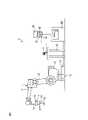
図1は、本実施の形態におけるロボット装置の概略図である。ロボット装置9は、作業ツールとしてのハンド2と、ハンド2を移動するロボット1とを備える。本実施の形態のロボット1は、複数の関節部を含む多関節ロボットである。ロボット1のそれぞれの構成部材は、ロボット1の駆動軸の周りに回転するように形成される。本実施の形態のロボット1は、ベース部14と、ベース部14に支持された旋回ベース13とを含む。旋回ベース13は、ベース部14に対して回転する。ロボット1は、上部アーム11および下部アーム12を含む。下部アーム12は、旋回ベース13に支持されている。上部アーム11は、下部アーム12に支持されている。ロボット1は、上部アーム11に支持されている手首部15を含む。手首部15のフランジ16には、ワークを把持したり解放したりするためのハンド2が固定されている。 FIG. 1 is a schematic diagram of a robot device according to the present embodiment. The robot device 9 includes a
本実施の形態のロボット1は、6個の駆動軸を有するが、この形態に限られない。任意の機構にて位置および姿勢を変更するロボットを採用することができる。また、本実施の形態の作業ツールは、ワークを把持するハンドであるが、この形態に限れられない。作業者は、ロボット装置が行う作業に応じた作業ツールを選定することができる。例えば、バリを除去する作業ツール、溶接を行う作業ツール、または接着剤を塗布する作業ツールなどを採用することができる。 The robot 1 of the present embodiment has six drive shafts, but is not limited to this embodiment. A robot that changes its position and posture by any mechanism can be adopted. Further, the work tool of the present embodiment is a hand that grips the work, but is not limited to this form. The worker can select a work tool according to the work performed by the robot device. For example, a work tool for removing burrs, a work tool for welding, a work tool for applying an adhesive, and the like can be adopted.
本実施の形態のロボット装置9には、基準座標系71が設定されている。図1に示す例では、ロボット1のベース部14に、基準座標系71の原点が配置されている。基準座標系71はワールド座標系とも称される。基準座標系71は、原点の位置が固定され、更に、座標軸の向きが固定されている座標系である。ロボット1の位置および姿勢が変化しても基準座標系71の位置および向きは変化しない。基準座標系71は、座標軸として、互いに直交するX軸、Y軸、およびZ軸を有する。また、X軸の周りの座標軸としてW軸が設定される。Y軸の周りの座標軸としてP軸が設定される。Z軸の周りの座標軸としてR軸が設定される。 A reference coordinate
本実施の形態では、作業ツールの任意の位置に設定された原点を有するツール座標系72が設定されている。本実施の形態のツール座標系72の原点は、工具先端点70に設定されている。ツール座標系72は、座標軸として、互いに直交するX軸、Y軸、およびZ軸を有する。図1に示す例では、ツール座標系72は、Z軸の延びる方向がハンド2の爪部の延びる方向と平行になるように設定されている。また、ツール座標系72は、X軸の周りのW軸、Y軸の周りのP軸、およびZ軸の周りのR軸を有する。例えば、ロボット1の位置は、工具先端点70の位置に相当する。また、ロボット1の姿勢は、基準座標系71に対するツール座標系72の向きに相当する。 In this embodiment, a tool coordinate
図2に、本実施の形態におけるロボット装置のブロック図を示す。図1および図2を参照して、ロボット1は、ロボット1の位置および姿勢を変化させるロボット駆動装置を含む。ロボット駆動装置は、アームおよび手首部等の構成部材を駆動するロボット駆動モータ22を含む。本実施の形態では、それぞれの駆動軸に対応して、複数のロボット駆動モータ22が配置されている。 FIG. 2 shows a block diagram of the robot device according to the present embodiment. With reference to FIGS. 1 and 2, the robot 1 includes a robot drive that changes the position and orientation of the robot 1. The robot drive device includes a
ロボット装置9は、ハンド2を駆動するハンド駆動装置を備える。ハンド駆動装置は、ハンド2の爪部を駆動するハンド駆動モータ21を含む。ハンド駆動モータ21が駆動することによりハンド2の爪部が開いたり閉じたりする。 The robot device 9 includes a hand drive device that drives the
ロボット装置9は、ロボット1およびハンド2を制御する制御装置4を備える。制御装置4は、制御を行う処理装置40と、作業者が処理装置40を操作するための教示操作盤37とを含む。処理装置40は、CPU(Central Processing Unit)と、CPUにバスを介して接続されたRAM(Random Access Memory)およびROM(Read Only Memory)とを有する演算処理装置(コンピュータ)を含む。ロボット1およびハンド2は、通信装置を介して制御装置4に接続されている。 The robot device 9 includes a
教示操作盤37は、通信装置を介して処理装置40に接続されている。教示操作盤37は、ロボット1およびハンド2に関する情報を入力する入力部38を含む。入力部38は、キーボードおよびダイヤルなどにより構成されている。作業者は、変数の設定値、および変数の許容範囲などを入力部38から処理装置40に入力することができる。教示操作盤37は、ロボット1およびハンド2に関する情報を表示する表示部39を含む。 The
作業者は、ロボット1を手動にて駆動することにより、ロボット1の教示点を設定することができる。制御装置4は、教示点に基づいて、ロボット1およびハンド2の動作を行うために動作プログラムを生成することができる。または、動作プログラムが制御装置4に入力されても構わない。 The operator can set the teaching point of the robot 1 by manually driving the robot 1. The
処理装置40は、ロボット1およびハンド2の制御に関する情報を記憶する記憶部42を含む。動作プログラムは、記憶部42に記憶される。本実施の形態のロボット装置9は、動作プログラムに基づいてワークを搬送する。ロボット1は、自動的に初期の位置から目標位置までワークを搬送することができる。 The
処理装置40は、ロボット1の動作を制御する動作制御部43を含む。動作制御部43は、動作プログラムに基づいて、ロボット1を駆動するための動作指令をロボット駆動部45に送出する。ロボット駆動部45は、ロボット駆動モータ22を駆動する電気回路を含む。ロボット駆動部45は、動作指令に基づいてロボット駆動モータ22に電気を供給する。また、動作制御部43は、ハンド2の動作を制御する。動作制御部43は、動作プログラムに基づいてハンド2を駆動する動作指令をハンド駆動部44に送出する。ハンド駆動部44は、ハンド駆動モータ21を駆動する電気回路を含む。ハンド駆動部44は、動作指令に基づいてハンド駆動モータ21に電気を供給する。 The
ロボット1は、ロボット1の位置および姿勢を検出するための状態検出器を含む。本実施の形態における状態検出器は、アーム等の駆動軸に対応するロボット駆動モータ22に取り付けられた位置検出器19を含む。位置検出器19の出力により、それぞれの駆動軸における構成部材の向きを取得することができる。例えば、位置検出器19は、ロボット駆動モータ22が駆動するときの回転角を検出する。本実施の形態では、複数の位置検出器19の出力に基づいて、ロボット1の位置および姿勢が検出される。 The robot 1 includes a state detector for detecting the position and posture of the robot 1. The state detector in this embodiment includes a
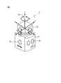
図3に、本実施の形態における操作装置の拡大斜視図を示す。図1から図3を参照して、本実施の形態におけるロボットの制御装置4は、作業者が手動にてロボット1の位置および姿勢を変更する操作を行う操作装置5を備える。本実施の形態では、操作装置5は不動の架台81に固定されている。作業者は、架台81の近傍に立って操作装置5を操作することにより、ロボット1の手動操作を実施することができる。 FIG. 3 shows an enlarged perspective view of the operating device according to the present embodiment. With reference to FIGS. 1 to 3, the
本実施の形態の操作装置5は、CPUおよびRAM等を含む演算処理部を含む。操作装置5は、通信を行うための無線通信部58を含む。また、教示操作盤37は、無線通信部としての無線ドングル36を含む。操作装置5は、教示操作盤37と無線にて互いに通信できるように形成されている。また、操作装置5は、教示操作盤37を介して、処理装置40と通信できるように形成されている。処理装置40は、操作装置5からの信号を処理することができる。 The
本実施の形態の操作装置5は、教示操作盤37と無線にて通信可能に形成されているが、この形態に限られない。操作装置5は、通信線を介して教示操作盤37に接続されていても構わない。または、操作装置5は、無線または通信線にて、処理装置40と通信が可能なように形成されていても構わない。 The operating
本実施の形態における操作装置5は、本体部51と、本体部51に支持された可動部としてのスティック52を含む。スティック52は、本体部51に対して動くように形成されている。本体部51は、架台81に固定されている。 The operating
図3には、スティック52の動作を説明するための操作座標系73が記載されている。操作座標系73の原点は、スティック52から手を離したときのスティック52の軸線上に配置することができる。また、操作座標系73の向きは、任意の向きに設定することができる。図3に示す例では、スティック52から手を離したときのスティック52の軸線に重なる様にZ軸を配置している。 FIG. 3 shows an operating coordinate
本実施の形態のスティック52は、操作座標系73のX軸方向およびY軸方向に倒すことができるように形成されている。すなわち、予め定められた回動中心の周りに、スティック52が回動するように形成されている。また、スティック52は、X軸およびY軸に挟まれる中間の領域においても倒すことができるように形成されている。このように、スティック52は、任意の方向に倒す操作が可能に形成されている。また、スティック52は、Z軸方向に引く操作または押す操作が可能なように形成されている。 The
本体部51の内部には、スティック52を中立状態に戻すように付勢する弾性部材としてのバネが配置されている。中立状態は、例えばスティック52の軸線が鉛直方向に延びる状態である。Z軸方向においては、押す操作および引く操作の操作可能な範囲の中央の位置が中立状態の位置に相当する。 Inside the
更に、本実施の形態における操作装置5は、スティック52を操作座標系73のZ軸の周りのR軸の方向に回転させることが出来るように形成されている。すなわち、作業者がスティック52を捩じることができるように形成されている。このときの中立状態の位置は、R軸に沿って捩じる操作が可能な範囲の中央の位置に対応する。 Further, the operating
操作装置5の演算処理部は、作業者の操作を検出するための操作検出部57を有する。作業者がスティック52を操作した場合には、操作検出部57は、スティック52の操作方向と操作量とを検出する。操作量としては、スティック52における予め定められた位置の移動量、またはスティック52が回動する時の回転中心の周りの回転角度を検出することができる。 The arithmetic processing unit of the
操作検出部57は、操作座標系73のそれぞれの座標値を用いて操作方向および操作量を検出することができる。特に、操作検出部57は、スティック52の中立状態からの操作量を検出できるように形成されている。このように、操作検出部57は、作業者が行う操作を検出することができる。なお、操作検出部は、CPUを有する演算処理部を含まなくても構わない。操作検出部は、機械的な機構により、作業者のスティックの操作を検出できるように形成されていても構わない。 The
本実施の形態における操作装置5は、架台81に固定されているが、この形態に限られない。操作装置5は、様々な位置に配置することができる。例えば、操作装置5は、ロボット1の手首部15またはハンド2に支持部材を配置して、支持部材に固定することができる。すなわち、ロボット1の手首部15またはハンド2と共に動くように操作装置5を配置することができる。この場合に、作業者は、ロボット1の近傍に立って操作装置5を操作することにより、ロボット1の位置および姿勢を手動にて変更することができる。または、操作装置は、作業者が手で持って操作しても構わない。 The operating
図4に、操作装置のスティックの操作方向と、ロボットが駆動する方向との対応を説明する操作装置およびロボットの概略図を示す。図2および図4を参照して、本実施の形態における処理装置40は、スティック52の操作を行っている期間は、ロボット1の位置および姿勢を連続的に変更するジョグ動作を実施可能に形成されている。また、処理装置40は、スティック52の操作に応じてロボット1の位置および姿勢を予め定められた微小量にて変更する寸動動作を実施可能に形成されている。本実施の形態の操作装置5は、ジョグ動作を行うジョグモードと、寸動動作を行うインチングモードとを切替えるボタン53を含む。作業者は、ボタン53を押すことにより、ジョグモードとインチングモードとを切り替えることができる。 FIG. 4 shows a schematic diagram of an operating device and a robot for explaining the correspondence between the operating direction of the stick of the operating device and the direction in which the robot is driven. With reference to FIGS. 2 and 4, the
(ジョグ動作の制御)
ロボット1の位置および姿勢を連続的に変更するジョグ動作について説明する。ジョグ動作を行う場合に、作業者は、制御モードをジョグモードに設定する。処理装置40は、スティック52を操作している期間中は、ロボット1の位置および姿勢を変更する。ジョグ動作では、操作装置5のスティック52の操作方向および操作量に応じてロボット1の位置および姿勢が変更される。(Control of jog movement)
A jog motion for continuously changing the position and posture of the robot 1 will be described. When performing the jog operation, the operator sets the control mode to the jog mode. The
本実施の形態における処理装置40は、操作装置5の操作に応じてロボット1の位置および姿勢を変更する手動制御部61を含む。手動制御部61は、操作装置5の操作に応じた動作指令を動作制御部43に送出する。動作制御部43は、動作指令に基づいてロボット1の位置および姿勢を変更する。 The
ジョグ動作では、手動制御部61は、操作座標系73における座標軸の方向と、ツール座標系72の座標軸の方向とが対応するようにロボット1を駆動することができる。例えば、作業者は、スティック52を操作座標系73のX軸方向に倒した場合には、手動制御部61は、工具先端点70がツール座標系72のX軸の方向に移動するようにロボット1を制御する。 In the jog operation, the
本実施の形態では、操作装置5が架台に固定されている。操作装置5の位置および向きは不動であるために、操作座標系73の位置および向きは固定されている。作業者は、設定値48として、操作座標系73の位置および向きを入力することができる。例えば、作業者は、基準座標系71に対する操作座標系73の位置および向きを予め入力することができる。また、手動制御部61は、位置検出器19の出力に基づいて、基準座標系71に対するツール座標系72の位置および向きを算出することができる。このために、手動制御部61は、操作座標系73に対するツール座標系72の相対的な位置および向きを算出することができる。 In this embodiment, the operating
操作装置5がハンドまたはロボットの手首部に固定されている場合にも同様に、基準座標系71に対する操作座標系73の位置および向きは、位置検出器19の出力に基づいて算出される。このために、手動制御部61は、操作座標系73に対するツール座標系72の相対的な位置および向きを算出することができる。 Similarly, when the
作業者が、操作座標系73の1つの方向にスティック52を操作した場合に、手動制御部61は、ツール座標系72(ハンド2)がスティック52を操作した方向に移動するように、ロボット1の位置および姿勢を変更する。 When the operator operates the
ここで、制御装置4は、ハンド2の姿勢を維持しながら工具先端点70の位置を移動する並進動作と、予め定められた点の位置を維持しながらハンド2の姿勢を変更する回転動作とを切替えることができるように形成されている。本実施の形態の回転動作では、工具先端点70を回転中心としてハンド2が回転する。作業者は、本体部51に配置されたボタン55を押すことにより、並進動作と回転動作とを切替えることができる。例えば、図3を参照して、並進動作では、スティック52を操作座標系73のX軸の方向に倒すことにより、ハンド2がツール座標系72のX軸の方向に移動するように制御される。回転動作では、スティック52を操作座標系73のX軸の方向に倒すことにより、ハンド2がツール座標系72のW軸の方向に回転するように制御される。 Here, the
ジョグ動作におけるハンド2の移動速度および回転速度(ツール座標系72の移動速度および回転速度)は、作業者が予め定めておいて、設定値48として記憶部42に記憶させておくことができる。また、ジョグ動作の移動量としては、作業者がスティック52を操作している期間中は、ロボット1の駆動が継続される。 The movement speed and rotation speed of the
上記のジョグ動作の形態においては、操作座標系73の座標軸と、ツール座標系72の座標軸とが対応するように、ロボット1の位置および姿勢を変更しているが、この形態に限られない。操作装置5のスティック52の操作に応じて、任意の方向に作業ツールが移動または回転するように、ロボット1を制御することができる。例えば、手動制御部61は、操作座標系73の座標軸と、基準座標系71の座標軸とが対応するように、ロボット1の位置および姿勢を変更しても構わない。例えば、スティック52を操作座標系73のX軸の方向に倒した場合に、手動制御部61は、工具先端点70の位置が基準座標系71のX軸の方向に移動するように制御しても構わない。 In the above-mentioned form of the jog operation, the position and posture of the robot 1 are changed so that the coordinate axes of the operation coordinate
または、手動制御部は、操作装置をロボットの手首部に配置した場合に、スティックを操作する方向に手首部が移動するように制御することができる。この場合に、スティックを操作する方向と手首部が移動する方向とが一致するように、操作座標系の座標軸とツール座標系の座標軸とを設定しても構わない。 Alternatively, the manual control unit can control the wrist portion to move in the direction in which the stick is operated when the operating device is arranged on the wrist portion of the robot. In this case, the coordinate axes of the operation coordinate system and the coordinate axes of the tool coordinate system may be set so that the direction in which the stick is operated and the direction in which the wrist is moved coincide with each other.
(寸動動作の制御)
次に、ロボット1の位置および姿勢を予め定められた微小量にて変更する寸動動作について説明する。寸動動作を実施する場合に、作業者は、ボタン53を押すことにより、制御モードをインチングモードに切り替える。インチングモードでのロボットの駆動量は、微小である。例えば、並進動作では、ハンド2の移動距離(ツール座標系72の移動距離)が10mm以下になるように設定される。より好ましくは、ハンド2の移動距離が5mm以下になるように設定される。回転動作では、例えば、ハンド2の回転角度(ツール座標系72の回転角度)が5°以下になるように設定される。より好ましくは、作業ツールの回転角度が1°以下になるように設定される。(Control of cun movement)
Next, a sizing motion that changes the position and posture of the robot 1 by a predetermined minute amount will be described. When performing the sizing operation, the operator switches the control mode to the inching mode by pressing the
(寸動動作を実施するか否かを判定する判定制御)
始めに、寸動動作を実施する否かを判定する判定制御について説明する。判定制御の第1の制御は、ジョグ動作の制御と同様である。作業者がスティック52を動かしたときに、手動制御部61は、寸動動作を実施する制御を実施する。すなわち、スティック52を操作した時間またはスティック52に加えられた力に関わらずに、スティック52が操作された時に、手動制御部61は、予め定められた移動量にて寸動動作を実施する。(Judgment control to determine whether or not to perform a cun motion)
First, a determination control for determining whether or not to perform a cun motion will be described. The first control of the determination control is the same as the control of the jog operation. When the operator moves the
判定制御の第2の制御および第3の制御では、手動制御部61は、スティック52が操作されてからの経過時間に基づいて、寸動動作を実施するか否かを判定する。図2を参照して、本実施の形態における手動制御部61は、スティック52の操作に関連する時間を測定する時間測定部62を有する。操作の経過時間の判定値は、作業者が予め定めておくことができる。経過時間の判定値としては、例えば1秒以下の時間を設定することができる。作業者は、判定値を設定値48として記憶部42に記憶させておくことができる。 In the second control and the third control of the determination control, the
判定制御の第2の制御では、手動制御部61は、スティック52が操作されてから手を離すまでの経過時間が、予め定められた判定値よりも長い場合には、寸動動作を実施しない。一方で、手動制御部61は、スティック52が操作されてから手を離すまでの経過時間が予め定められた判定値以下の場合には、寸動動作を実施する。手動制御部61は、スティック52が中立状態に戻った場合に、作業者がスティック52から手を離したと判定する。 In the second control of the determination control, the
第2の制御では、予め定められた判定値よりも長い時間にて、作業者がスティック52の操作を継続した場合には、手動制御部61は寸動動作を実施しない。一方で、予め定められた判定値以下の期間に、作業者が手を離した場合に、手動制御部61は、1回の寸動動作を実施する。 In the second control, if the operator continues to operate the
寸動動作では、僅かにロボット1の位置および姿勢が変化する。第2の制御では、作業者が短時間にてスティック52を操作した場合に寸動動作を実施する。第2の制御では、僅かな移動量の寸動動作を実施する場合に、僅かな時間の操作を実施すれば良く、作業者は、違和感がなく寸動動作を実施することができる。または、作業者は、現在の制御モードがインチングモードであるにも関わらずに、現在の制御モードがジョグモードであると誤解している場合がある。このような場合に、スティック52を長い時間にて操作してロボット1が駆動することを回避することができる。 In the sizing motion, the position and posture of the robot 1 change slightly. In the second control, when the operator operates the
判定制御の第3の制御では、手動制御部61は、スティック52が操作されてから手を離すまでの経過時間が、予め定められた判定値よりも短い場合には、寸動動作を実施しない。一方で、スティック52が操作されてからの経過時間が予め定められた判定値以上の場合に、手動制御部61は、寸動動作を実施する。 In the third control of the determination control, the
第3の制御では、予め定められた判定値よりも短い時間内に、作業者がスティック52から手を離した場合に、手動制御部61は寸動動作を実施しない。一方で、予め定められた判定値以上の時間にて、スティック52の操作を継続した場合に、手動制御部61は、1回の寸動動作を実施する。第3の制御を実施することにより、作業者が誤ってスティックを操作したり、作業者がスティックにぶつかったりした場合に、寸動動作が実施されることを回避できる。 In the third control, when the operator releases the
次に、判定制御の第4の制御および第5の制御では、手動制御部61は、スティック52が操作された力の大きさに基づいて、寸動動作を実施するか否かを判定する。このような力の判定値は、作業者が予め定めておくことができる。そして判定値は、設定値48として記憶部42に記憶させておくことができる。大きさの判定値は、例えば、5N以下の値を設定することができる。より好ましくは、力の大きさの判定値は、2N以下の値を設定することができる。または、力の判定値は、スティック52の移動量に基づいて設定しても構わない。例えば、力の判定値は、スティック52の最大の移動量の1/2の位置まで操作する時の大きさに設定することができる。 Next, in the fourth control and the fifth control of the determination control, the
手動制御部61は、スティック52が操作されたときにスティック52に加えられた力の大きさを検出する力検出部63を有する。力検出部63は、操作検出部57の出力に基づいてスティック52が操作された力の大きさを検出する。本実施の形態の力検出部63は、スティック52の中立状態からの操作量を、操作検出部57から取得する。力検出部63は、スティック52の操作量に基づいて作業者が加えた力の大きさを算出することができる。 The
本実施の形態においては、前述のように、本体部51の内部に、スティック52が中立状態に戻るように、ばねが配置されている。操作検出部57にて検出される操作量が大きくなるほど、作業者にて加えられた力は大きくなる。力検出部63は、スティック52の操作量に基づいて、スティック52に加えられた力の大きさを算出することができる。 In the present embodiment, as described above, a spring is arranged inside the
判定制御の第4の制御では、手動制御部61は、スティック52が操作された力の大きさが予め定められた判定値以上の場合に、寸動動作を実施しない制御を実施する。一方で、手動制御部61は、スティック52が操作された力の大きさが予め定められた判定値未満の場合に、寸動動作を実施する。手動制御部61は、1回の操作に対して1回の寸動動作を実施する。 In the fourth control of the determination control, the
第4の制御においては、小さな力で寸動動作を実施することができる。スティック52の僅かな移動量にて寸動動作を実施することができる。このために、寸動動作を複数回実施する場合に、短時間で寸動動作を実施することができる。このために、目標の位置および姿勢まで短時間でロボット1を駆動することができる。 In the fourth control, the pun motion can be performed with a small force. The pun movement can be performed with a small amount of movement of the
判定制御の第5の制御では、手動制御部61は、スティック52が操作された力の大きさが予め定められた判定値以下の場合に、寸動動作を実施しない。一方で、手動制御部61は、スティック52が操作された時の力の大きさが予め定められた判定値よりも大きい場合に、寸動動作を実施する。手動制御部61は、1回の操作に対して1回の寸動動作を実施する。 In the fifth control of the determination control, the
第5の制御においては、スティック52に加えられた力が大きな場合に、寸動動作を実施する。このために、作業者が誤ってスティック52に触れたときに、寸動動作が実施されることを回避することができる。 In the fifth control, when the force applied to the
なお、第4の制御および第5の制御においては、時間測定部62にてスティック52を操作する時間を測定しても構わない。スティック52を操作する時間の範囲を定めることができる。手動制御部61は、この時間の範囲内にてスティックに加わる力の判定を行っても構わない。 In the fourth control and the fifth control, the time for operating the
また、処理装置40は、ロボット1の寸動動作を実施するか否かを判定する判定制御に関して、上記の複数の制御を実施できるように形成されていても構わない。この場合には、処理装置40は、複数の制御を切替えるように形成することができる。 Further, the
本実施の形態の判定制御では、寸動動作を実施するか否かを操作装置の操作によって判定することができるために、手動操作における操作性が向上する。 In the determination control of the present embodiment, it is possible to determine whether or not to perform the sizing operation by operating the operating device, so that the operability in the manual operation is improved.
(作業ツールの移動方向に関する移動方向制御)
次に、作業ツールの移動方向に関する制御について説明する。作業ツールの移動方向に関する第1の制御では、前述のジョグ動作の制御と同様の制御を寸動動作おいても実施する。手動制御部61は、操作座標系73におけるスティック52の操作の方向に対応するツール座標系72の方向に向かってハンド2が移動するように、ロボット1の位置および姿勢を変更することができる。(Movement direction control regarding the movement direction of the work tool)
Next, control regarding the movement direction of the work tool will be described. In the first control regarding the moving direction of the work tool, the same control as the above-mentioned control of the jog movement is performed even in the cun movement. The
例えば、作業者は、並進動作または回転動作をボタン55にて選択する。手動制御部61は、操作座標系73に基づくスティック52の操作を取得する。手動制御部61は、スティック52の操作の方向に対応するツール座標系72の方向に、ハンド2が移動または回転するように、ロボット1の位置および姿勢を変更する。例えば、並進動作を実施する制御モードの時に、作業者が操作座標系73のX軸の方向にスティック52を倒したときに、手動制御部61は、ツール座標系72のX軸の方向に工具先端点70が移動するように、ロボット1の位置および姿勢を変更する。 For example, the operator selects a translation operation or a rotation operation with the
第1の制御では、スティック52を操作する方向とハンド2が移動する方向とが対応するために、作業者は、教示操作盤37を見なくてもロボット1を操作することができる。例えば、教示操作盤37に配置されている動作方向に対応するボタンの位置を確認せずに、ロボット1を見ながら操作することができる。 In the first control, since the direction in which the
次に、作業ツールの移動方向に関する第2の制御では、手動制御部61は、スティック52の操作の種類に関わらずに、予め定められた設定方向にハンド2が移動するように、寸動動作を実施する。作業者は、ハンド2が移動する設定方向を設定し、設定値48として記憶部42に記憶させておくことができる。 Next, in the second control regarding the moving direction of the work tool, the
例えば、ハンド2が移動する設定方向として、基準座標系71のY軸の正側の方向を設定することができる。作業者が、スティック52を、操作座標系73のX軸方向に倒したり、Y軸方向に倒したり、Z軸方向に押したり、Z軸方向に引いたりしても、手動制御部61は、工具先端点70がY軸の正側の方向に移動するようにロボット1を制御する。 For example, as the setting direction in which the
または、作業者は、ハンド2が移動する曲線状の移動経路を予め設定しておくことができる。作業者は、曲線状の移動経路を設定値48として記憶部42に記憶させておくことができる。移動経路は、任意の座標系にて設定することができる。例えば、移動経路としては、基準座標系71にて表現した経路を設定することができる。移動経路には、ハンド2が移動する方向に加えて、ハンド2の姿勢が含まれる。 Alternatively, the operator can preset a curved movement path in which the
図5に、曲線状の移動経路を説明する概略図を示す。図5には、基準座標系71の座標軸が示されている。作業者は、ロボット1の周りの空間において、工具先端点70が移動する移動経路85を設定しておくことができる。また、移動経路85にはハンド2の姿勢を設定しておくことができる。例えば、工具先端点70が位置P0に配置されている。作業者は、スティック52を任意の方向に操作することにより、工具先端点70が位置P0から位置P1に移動するようにロボット1の位置および姿勢が変化する。工具先端点70は、移動経路85に沿って移動する。 FIG. 5 shows a schematic diagram illustrating a curved movement path. FIG. 5 shows the coordinate axes of the reference coordinate
第2の制御を実施することにより、予め定められた移動経路85に沿ってハンド2が移動するように、寸動動作を実施することができる。例えば、ワークの角部に形成されたバリの除去を実施する場合に、作業ツールに取り付けられた工具が角部の形状に沿って移動するか否かを確認する場合がある。作業者は、角部の形状に沿う曲線状の移動経路を設定することができる。そして、作業者は、寸動動作を行うことにより、作業ツールの位置および姿勢を移動経路に沿って微小量ごとに変化させる。作業者は、微小区間ごとに作業ツールの位置および姿勢が適正であるか否かを確認することができる。なお、上記の例では、移動経路が曲線状であるが、この形態に限られない。移動経路は、直線状であっても構わない。 By carrying out the second control, it is possible to carry out the pun motion so that the
次に、作業ツールの移動方向に関する第3の制御では、作業者がスティック52を操作する方向に対して予め定められた角度にてずらした方向にハンド2が移動するように、ロボット1を制御することができる。このような予め定められた角度は、作業者が予め設定して設定値48として記憶部42に記憶させておくことができる。 Next, in the third control regarding the moving direction of the work tool, the robot 1 is controlled so that the
例えば、作業者は、操作方向をずらす角度として、R軸の正側の30°を設定することができる。並進動作において、作業者がスティック52を操作座標系73のX軸の正側に倒す操作を実施する。手動制御部61は、ツール座標系72のX軸の正側の方向からR軸の正側の方向に30°ずらした方向にハンド2が移動するように、ロボット1の位置および姿勢を制御することができる。 For example, the operator can set 30 ° on the positive side of the R axis as an angle for shifting the operation direction. In the translation operation, the operator performs an operation of tilting the
処理装置40は、上記のハンドの移動方向に関する複数の制御を実施できるように形成されていても構わない。この場合には、処理装置40は、複数の制御の切り替えが可能な様に形成されることができる。 The
本実施の形態の移動方向制御では、ハンドを移動する方向に対応した操作装置の操作にてハンドを所望の方向に移動することができる。このために、手動操作における操作性が向上する。 In the movement direction control of the present embodiment, the hand can be moved in a desired direction by operating the operating device corresponding to the direction in which the hand is moved. Therefore, the operability in the manual operation is improved.
(ハンドの移動量に関する移動量制御)
次に、1回の寸動動作においてハンド2が位置および姿勢を変更する移動量に関する制御について説明する。並進動作においては、例えば、ハンド2(または工具先端点70)が移動する時の長さが移動量に対応する。また、回転動作については、例えば、ハンド2が回転する回転角度が移動量に対応する。移動量は、様々な形態で設定することができる。作業者は、移動量を予め定めて、設定値48として記憶部42に記憶させておくことができる。手動制御部61は、ハンド2を移動する方向が決まった時に、予め定められた移動量にてハンド2が移動するように、ロボット1の位置および姿勢を変更する。(Movement amount control related to the movement amount of the hand)
Next, the control regarding the movement amount in which the
ハンドの移動量に関する第1の制御では、並進動作を行う場合に、作業者は、現在の位置P0から移動後の位置P1までの直線距離を移動量として設定する。すなわち、工具先端点70が移動する直線距離を移動量として設定する。また、作業者は、回転動作を行う場合に、ハンド2の回転角度を移動量として設定することができる。 In the first control regarding the movement amount of the hand, when performing the translation operation, the operator sets the linear distance from the current position P0 to the position P1 after the movement as the movement amount. That is, the linear distance at which the
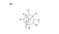
図6に、第1の制御における移動量を説明する第1のグラフを示す。図6には、並進動作における作業ツールの移動量がツール座標系72にて示されている。すなわち、工具先端点70が、寸動動作の開始点の位置P0から寸動動作が終了した時の位置P1に移動する距離が示されている。全ての方向における移動量は、球87にて示されている。図6では、寸動動作における移動量は、全ての方向について等しい距離が設定されている。例えば、矢印94に示す移動方向における移動量と、矢印95に示す移動方向における移動量とは、等しく設定されている。 FIG. 6 shows a first graph illustrating the amount of movement in the first control. FIG. 6 shows the movement amount of the work tool in the translation operation in the tool coordinate
図7に、第1の制御における移動量を説明する第2のグラフを示す。図7には、並進動作における作業ツールの移動量がツール座標系72にて示されている。それぞれの移動方向において、移動量が異なるように設定することができる。第2のグラフにおいては、移動量は、四角柱88にて示されている。図7に示す例においては、X軸の方向には移動量が大きく設定され、Y軸の方向およびZ軸の方向には、移動量は小さく設定されている。この結果、矢印96に示す移動方向の移動量は、矢印97に示す移動方向の移動量よりも小さくなる。このように、移動量は、それぞれの方向において任意の距離を設定することができる。 FIG. 7 shows a second graph illustrating the amount of movement in the first control. FIG. 7 shows the movement amount of the work tool in the translation operation in the tool coordinate
上記の図6および図7に示す例では、並進動作について説明を行っているが、回転動作についての同様の制御を実施することができる。例えば、ツール座標系72のW軸、P軸、およびR軸について、同一の移動量(回転角度)を設定することができる。または、ツール座標系72のW軸、P軸、およびR軸ごとに異なる移動量(回転角度)を設定しても構わない。 In the examples shown in FIGS. 6 and 7 above, the translational operation is described, but the same control for the rotational operation can be performed. For example, the same movement amount (rotation angle) can be set for the W axis, P axis, and R axis of the tool coordinate
次に、ハンドの移動量に関する第2の制御では、並進動作において、現在の位置P0から寸動動作が終了する位置P1までの直線移動において、予め定められた平面に投影した長さを移動量に設定する。 Next, in the second control regarding the movement amount of the hand, in the translational movement, in the linear movement from the current position P0 to the position P1 where the cun movement ends, the length projected on a predetermined plane is the movement amount. Set to.
図8に、直線の移動経路をXY平面に投影した長さを説明する概略図を示す。図8の移動経路は、ツール座標系72にて示されている。ここでの例では、予め定められた平面としてXY平面が設定されている。寸動動作を行うことにより、工具先端点70は位置P0から位置P1に移動する。この時に、作業者は、移動量として例えばX軸およびY軸を含むXY平面に移動経路を投影した距離dxyを設定することができる。手動制御部61は、移動方向に基づいてXY平面において距離dxyになる目標の位置P1を算出する。手動制御部61は、工具先端点70が位置P0から位置P1に移動するように、ロボット1の位置および姿勢を変更する。 FIG. 8 shows a schematic diagram illustrating the length of the linear movement path projected onto the XY plane. The movement path of FIG. 8 is shown in the tool coordinate
次に、移動量に関する第3の制御は、図5に示すように、ハンド2が移動する曲線状の移動経路85が予め定められている場合の制御である。作業者がスティック52の操作の種類の関わらず、工具先端点70が移動経路85に沿って移動する。 Next, as shown in FIG. 5, the third control regarding the movement amount is the control when the
図9に、第3の制御の移動量を説明する図を示す。第3の制御においては、寸動動作により現在の位置P0から位置P1に移動する。この場合の移動量は、予め定められた平面に投影した長さにて設定されている。ここでの例では、予め定められた平面としてXY平面が設定されている。作業者は、XY平面に投影された長さdxyを移動量に設定することができる。手動制御部61は、位置P0の位置および移動経路85に基づいて、投影された長さが長さdxyになる位置P1を算出することができる。手動制御部61は、工具先端点70が移動経路85に沿って位置P0から位置P1に向かって移動するように、ロボット1の位置および姿勢を変更する。 FIG. 9 shows a diagram illustrating a movement amount of the third control. In the third control, the position P0 is moved from the current position P0 by the cun motion. The amount of movement in this case is set by a length projected onto a predetermined plane. In the example here, the XY plane is set as a predetermined plane. The operator can set the length dxy projected on the XY plane as the movement amount. The
次に、移動量に関する第4の制御は、図5に示すように、ハンド2が移動する曲線状の移動経路85が予め定められている場合の制御である。第4の制御では、移動量として、移動経路85に沿った移動長さが設定される。 Next, as shown in FIG. 5, the fourth control regarding the movement amount is the control when the
図10に、第4の制御の移動量を説明する図を示す。移動経路85は曲線状に設定されている。ロボット1の工具先端点70は、移動経路85に沿って位置P0から位置P1まで移動する。第4の制御においては、位置P0から位置P1までの移動経路85に沿った移動長さとして、長さdxyを移動量に設定することができる。手動制御部61は、位置P0の位置および移動経路85に基づいて、移動経路85に沿って移動する移動長さがdxyになる位置P1を算出する。操作装置5を操作したときに、手動制御部61は、工具先端点70が移動経路85に沿って位置P0から位置P1に向かって移動するように、ロボット1の位置および姿勢を変更する。 FIG. 10 shows a diagram illustrating a movement amount of the fourth control. The
本実施の形態の移動量制御では、それぞれのハンドを移動する形態に対応して、移動量を適切な方法にて設定することができる。このために、手動操作における操作性が向上する。 In the movement amount control of the present embodiment, the movement amount can be set by an appropriate method according to the mode in which each hand is moved. Therefore, the operability in the manual operation is improved.
(移動量および移動方向を設定する設定制御)
次に、寸動動作における移動量および移動方向を設定する設定制御について説明する。設定制御の第1の制御では、教示操作盤37を操作することにより、ハンド2の移動量および移動方向を設定する。作業者は、表示部39を見ながら入力部38を操作することにより、移動量を設定する。(Setting control to set the movement amount and movement direction)
Next, the setting control for setting the movement amount and the movement direction in the cun motion will be described. In the first control of the setting control, the movement amount and the movement direction of the
または、移動量および移動方向を設定するために、教示操作盤37とは異なる入力装置を配置することができる。例えば、スライダー式のハンドルを有する入力装置または回転式のつまみを有する入力装置を教示操作盤37に接続することができる。作業者は、教示操作盤37の表示部39を見ながらスライダー式のハンドルを倒すことにより、移動量および移動方向を設定することができる。または、作業者は、教示操作盤37の表示部39を見ながらつまみを回転することにより、移動量および移動方向を設定することができる。 Alternatively, an input device different from the
設定制御の第2の制御から第6の制御では、本実施の形態の操作装置5を操作することにより、移動量および移動方向を設定する。図7に示すように、操作座標系73のX軸、Y軸、およびZ軸ごとに移動量を変化させる場合には、それぞれの座標軸ごとに移動量を設定することができる。制御装置4は、ロボット1の操作を行う操作モードと設定値の設定を行う設定モードとを切り替えることができるように形成されている。設定モードは、移動量を設定するモードと、移動方向を設定するモードとを含む。移動量を設定する場合に、作業者は、設定モードのうち移動量を設定するモードに切り替える。移動方向を設定する場合に、作業者は、設定モードのうち移動方向を設定するモードに切り替える。 In the second control to the sixth control of the setting control, the movement amount and the movement direction are set by operating the
設定制御の第2の制御および第3の制御では、手動制御部61は、操作装置5のスティック52を操作する時間に基づいて、移動量を設定する。時間測定部62は、スティック52を操作してからの時間を測定する。 In the second control and the third control of the setting control, the
設定制御の第2の制御では、手動制御部61は、スティック52を予め定められた判定値の時間内に操作する回数に基づいて移動量を設定する。例えば、5秒以内にスティック52を操作座標系73のZ軸の方向に2回押した場合には、移動量を5mmに設定することができる。また、5秒以内にスティック52を操作座標系73のZ軸の方向に3回押した場合には、移動量を10mmに設定することができる。 In the second control of the setting control, the
設定制御の第3の制御では、手動制御部61は、スティック52の操作を継続する時間に基づいて移動量を設定する制御を実施する。操作を継続する時間の判定値は、予め定めておくことができる。例えば、スティック52をX軸の正側に倒したときに、1秒以内に手を離してスティック52が中立状態に戻った場合に、手動制御部61は、移動量を5mmに設定することができる。また、スティック52をX軸の正側に倒したときに、手を離すまでの経過時間が1秒よりも長い場合には、移動量を10mmに設定することができる。 In the third control of the setting control, the
設定制御の第4の制御では、手動制御部61は、スティック52に加える力の大きさに基づいて移動量を設定する。力検出部63は、スティック52に加わる力を検出する。手動制御部61は、力検出部63にて取得した力の大きさに応じて移動量を設定する。力の大きさの判定値は、予め定めておくことができる。力の大きさの判定値は、例えば、5Nに設定することができる。作業者がX軸方向の正側にスティック52を判定値よりも弱い力にて操作した場合には、移動量を5mmに設定することができる。また、作業者がX軸方向の正側にスティック52を判定値以上の力にて操作した場合には、移動量を10mmに設定することができる。 In the fourth control of the setting control, the
移動方向の設定については、次の第5の制御と第6の制御とを実施することができる。設定制御の第5の制御では、作業ツールの移動方向に関する制御のうち第2の制御において、予め定められた移動方向にハンド2を移動する場合に実施することができる。作業者は、操作座標系73において移動方向に対応する方向にスティック52を操作することにより、移動方向を設定することができる。 Regarding the setting of the moving direction, the following fifth control and sixth control can be carried out. The fifth control of the setting control can be executed when the
設定制御の第6の制御では、移動量の設定と同様に、手動制御部61は、スティック52を予め定められた判定値の時間内に操作する回数に基づいて移動方向を設定することができる。例えば、5秒以内にスティック52を操作座標系73のZ軸の方向に2回押した場合に、移動方向をX軸の正側の方向に設定することができる。また、5秒以内にスティック52を操作座標系73のZ軸の方向に3回押した場合には、移動方向をX軸の正側の方向に設定することができる。 In the sixth control of the setting control, the
また、作業ツールの移動方向に関する制御のうち第3の制御において、スティック52を操作する方向に対してずらした角度を設定する場合にも、スティック52を操作する回数に基づいて、ずらす角度を設定することができる。 Further, in the third control of the control related to the moving direction of the work tool, even when the angle shifted with respect to the direction in which the
移動量および移動方向を設定する制御については、上記の設定の制御を組み合わせることができる。作業者は、制御装置4を設定値の設定を行う設定モードに切り替える。1回目のスティック52の操作にて移動方向を設定することができる。2回目のスティック52の操作にて移動量を設定することができる。 For the control for setting the movement amount and the movement direction, the control of the above settings can be combined. The operator switches the
例えば、1回目にスティック52を操作する方向を工具先端点70が移動する移動方向に設定することができる。2回目の操作では、スティック52をZ軸方向に押す時間に基づいて、移動量を設定することができる。例えば、スティック52を押す時間が1秒以内の場合に、移動量を5mmに設定することができる。または、スティック52を押す時間が1秒よりも長い場合に、移動量を10mmに設定することができる。このように、移動量および移動方向を、連続して設定することができる。 For example, the direction in which the
なお、移動量および移動方向の設定については、上記の形態に限られない。例えば、教示操作盤とは異なる装置にて設定した移動量および移動方向を、通信装置を介して処理装置に入力しても構わない。 The movement amount and the movement direction are not limited to the above modes. For example, the movement amount and the movement direction set by the device different from the teaching operation panel may be input to the processing device via the communication device.
本実施の形態の設定制御の第2の制御から第6の制御では、操作装置の操作により、移動量および移動方向を設定することができる。このために、手動操作における操作性が向上する。 In the second control to the sixth control of the setting control of the present embodiment, the movement amount and the movement direction can be set by operating the operating device. Therefore, the operability in the manual operation is improved.
(ロボットの動作を許可する許可制御)
本実施の形態の操作装置5には、イネーブルスイッチの機能を付与することができる。イネーブルスイッチは、押すことによりロボットの動作を許可するスイッチである。例えば、イネーブルスイッチを押している期間に、ロボットの動作を行えるように制御することができる。または、イネーブルスイッチを1回押すとロボットの動作を許可し、再度、イネーブルスイッチを押すとロボットの動作を禁止する制御を実施することができる。(Permission control to allow robot movement)
The
本実施の形態のロボット1の動作を許可する第1の制御では、手動制御部61は、スティック52が操作されてからの経過時間に基づいて、ロボット1の動作を許可するか禁止するかを判定する。作業者が制御装置4の電源を入れた直後には、手動制御部61は、ロボット1の動作を禁止している。この状態で、作業者がスティック52を操作する。 In the first control for permitting the operation of the robot 1 of the present embodiment, the
時間測定部62は、スティック52が操作されてからの経過時間を測定する。作業者がスティック52を操作してから手を離すまで(スティック52が中立状態に戻るまで)の経過時間が、予め定められた時間の判定値未満の場合に、手動制御部61は、ロボット1の動作を許可する制御を実施する。一方で、作業者がスティック52を操作してから手を離すまでの経過時間が、予め定められた時間の判定値以上の場合に、手動制御部61は、ロボット1の動作を禁止する制御を実施する。時間の判定値としては、例えば、1秒以下の時間を設定することができる。 The
すなわち、作業者が短時間にてスティック52を操作した場合に、手動制御部61は、ロボット1の動作を許可する。例えば、ロボット1を動作させる操作を行う前に、スティック52を操作座標系73のZ軸の方向に短時間押すことにより、手動制御部61は、ロボット1の動作を許可する制御を実施する。 That is, when the operator operates the
または、作業者がスティック52を操作してから手を離すまでの経過時間が、予め定められた時間の判定値よりも大きい場合に、手動制御部61は、ロボット1の動作を許可する制御を実施しても構わない。すなわち、作業者が長い時間にてスティック52を操作した場合に、手動制御部61は、ロボット1の動作を許可することができる。この時の時間の判定値としても、例えば、1秒以下の時間を設定することができる。 Alternatively, when the elapsed time from the operation of the
ロボット1の動作を許可する第2の制御では、手動制御部61は、スティック52が操作された力の大きさに基づいて、ロボット1の動作を許可するか禁止するかを判定する。手動制御部61がロボット1の動作を禁止している状態において、作業者がスティック52を操作する。力検出部63は、スティック52に加えられる力の大きさを検出する。スティック52が操作された力の大きさが予め定められた判定値より大きい場合に、手動制御部61は、ロボット1の動作を許可する制御を実施する。力の大きさの判定値は、例えば、5N以下の値を設定することができる。より好ましくは、力の大きさの判定値は、2N以下の値を設定することができる。 In the second control for permitting the operation of the robot 1, the
このように、作業者が強い力にてスティック52を操作した場合に、手動制御部61は、ロボット1の動作を許可する制御を実施する。例えば、作業者がスティック52を最も深い位置まで押したときに、手動制御部61は、ロボット1の動作を許可する制御を実施する。スティック52が操作された力の大きさが予め定められた判定値以下の場合には、手動制御部61は、ロボット1の動作を禁止する制御を実施する。 In this way, when the operator operates the
または、スティック52が操作された力の大きさが予め定められた判定値より小さい場合に、手動制御部61は、ロボット1の動作を許可する制御を実施しても構わない。すなわち、作業者が弱い力にてスティック52を操作した場合に、ロボット1の動作を許可し、作業者が強い力にてスティック52を操作した場合に、ロボット1の動作を禁止する制御を実施しても構わない。この場合に力の判定値についても、例えば、5N以下の値を設定することができる。より好ましくは、力の大きさの判定値は、2N以下の値を設定することができる。 Alternatively, when the magnitude of the operated force of the
このように、手動制御部61は、作業者がスティックを操作する時間またはスティックを操作する力の大きさに基づいて、ロボット1の動作を許可する状態とロボット1の動作を禁止する状態とに切り替えることができる。ロボット1の動作を許可する状態では、手動制御部61は、作業者のスティック52の操作に応じてロボット1を駆動する。一方で、ロボット1の動作を禁止する状態では、作業者がスティック52を操作しても、手動制御部61はロボット1を駆動しない。 As described above, the
ロボット1の動作が許可された後には、作業者はロボット1を駆動することができる。ここで、時間測定部62は、作業者がスティック52を操作しない時間を測定することができる。作業者がスティック52を操作しない時間が、予め定められた時間の判定値を超えた場合に、手動制御部61は、ロボット1の動作を禁止する制御を実施することができる。すなわち、作業者がスティック52を操作しない時間が長い場合に、手動制御部61は、ロボット1の動作を禁止する制御を実施することができる。 After the operation of the robot 1 is permitted, the operator can drive the robot 1. Here, the
または、スティック52の操作により、手動制御部61は、ロボット1の動作を禁止する制御を実施することができる。例えば、作業者がスティック52をR軸方向にねじる操作を実施した場合に、手動制御部61は、ロボット1の動作を禁止する制御を実施することができる。作業者は、ロボット1の動作を再開する場合には、手動制御部61がロボット1の動作を許可するように、前述のスティック52の操作を行うことができる。 Alternatively, by operating the
本実施の形態の許可制御では、ロボットの動作を許可する状態および禁止する状態を操作装置にて切り替えることができる。このために、ロボット1の手動操作における操作性が向上する。 In the permission control of the present embodiment, the state in which the operation of the robot is permitted and the state in which the operation of the robot is prohibited can be switched by the operating device. Therefore, the operability in the manual operation of the robot 1 is improved.
また、制御装置4を起動した場合に、ロボット1の動作を許可するためのスティック52の操作を実施した直後に、スティック52の操作により、上記の寸動動作を実施するか否かを判定する判定制御、または作業ツールの移動方向に関する移動方向制御などについて、制御の種類を選定することができる。例えば、ロボット1の動作を許可するようにスティック52の操作を実施した直後に、スティック52をZ軸方向に押しながらX軸の正側に倒した場合には、複数の判定制御のうち第1の制御を実施するように設定することができる。または、スティック52をZ軸方向に押しながらX軸の負側に倒した場合には、第2の制御を実施するように設定することができる。または、スティック52をZ軸方向に押しながらY軸の正側に倒した場合には、第3の制御を実施するように設定することができる。このように、スティック52の連続する操作によって、予め定められた複数の制御を選択して実施しても構わない。 Further, when the
上記の実施の形態は、適宜組み合わせることができる。上述のそれぞれの図において、同一または相等する部分には同一の符号を付している。なお、上記の実施の形態は例示であり発明を限定するものではない。また、実施の形態においては、特許請求の範囲に示される実施の形態の変更が含まれている。 The above embodiments can be combined as appropriate. In each of the above figures, the same or equal parts are designated by the same reference numerals. It should be noted that the above embodiment is an example and does not limit the invention. Further, in the embodiment, the modification of the embodiment shown in the claims is included.
1 ロボット
2 ハンド
4 制御装置
5 操作装置
36 無線ドングル
37 教示操作盤
40 処理装置
42 記憶部
48 設定値
51 本体部
52 スティック
57 操作検出部
58 無線通信部
61 手動制御部
62 時間測定部
63 力検出部
70 工具先端点
85 移動経路1
Claims (5)
Translated fromJapanese前記操作装置からの信号を処理する処理装置とを備え、
前記操作装置は、押す操作、引く操作、および予め定められた方向に倒す操作が可能な可動部と、可動部の操作を検出する操作検出部とを有し、
前記処理装置は、操作検出部にて検出された可動部の操作に応じてロボットの位置および姿勢を予め定められた微小量にて変更する寸動動作を制御する手動制御部を含み、
前記手動制御部は、操作検出部の出力に基づいて可動部が操作された力の大きさを検出する力検出部を有し、可動部が操作された力の大きさに基づいて、前記寸動動作を実施するか否かを判定し、
前記処理装置は、ロボットを操作する操作モードと、前記寸動動作を実施する時のロボットに取り付けられた作業ツールの移動量および移動方向のうち少なくとも一方を設定する設定モードとが切り替え可能に形成されており、
前記手動制御部は、設定モードにおいて、可動部を操作する回数に応じて作業ツールの移動量および移動方向のうち少なくとも一方を設定する、ロボットの制御装置。An operating device that allows the operator to manually change the position and posture of the robot,
A processing device for processing a signal from the operating device is provided.
The operating device has a movable portion capable of pushing, pulling, and tilting in a predetermined direction, and an operation detecting unit for detecting the operation of the movable portion.
The processing device includes a manual control unit that controls a cun motion that changes the position and posture of the robot by a predetermined minute amount according to the operation of the movable unit detected by the operation detection unit.
The manual control unit has a force detection unit that detects the magnitude of the force operated by the movable unit based on the output of the operation detection unit, and the dimension is based on the magnitude of the force operated by the movable unit. Determine whether or not to carry out dynamic movement,
The processing device is formed so as to be switchable between an operation mode for operating the robot and a setting mode for setting at least one of the movement amount and the movement direction of the work tool attached to the robot when performing the cun motion. Has been
The manual control unit is a robot control device that sets at least one of the movement amount and the movement direction of the work tool according to the number of times the movable part is operated in the setting mode.
前記操作装置からの信号を処理する処理装置とを備え、
前記操作装置は、押す操作、引く操作、および予め定められた方向に倒す操作が可能な可動部と、可動部の操作を検出する操作検出部とを有し、
前記処理装置は、操作検出部にて検出された可動部の操作に応じてロボットの位置および姿勢を予め定められた微小量にて変更する寸動動作を制御する手動制御部を含み、
前記手動制御部は、操作検出部の出力に基づいて可動部が操作された力の大きさを検出する力検出部を有し、可動部が操作された力の大きさに基づいて、前記寸動動作を実施するか否かを判定し、
前記処理装置は、ロボットを操作する操作モードと、前記寸動動作を実施する時のロボットに取り付けられた作業ツールの移動量および移動方向のうち少なくとも一方を設定する設定モードとが切り替え可能に形成されており、
前記手動制御部は、可動部が操作されてからの経過時間を測定する時間測定部を有し、
前記手動制御部は、設定モードにおいて、1回目の可動部を操作する方向に基づいて移動方向を設定し、2回目の可動部を操作する時間の長さに基づいて移動量を設定する、ロボットの制御装置。An operating device that allows the operator to manually change the position and posture of the robot,
A processing device for processing a signal from the operating device is provided.
The operating device has a movable portion capable of pushing, pulling, and tilting in a predetermined direction, and an operation detecting unit for detecting the operation of the movable portion.
The processing device includes a manual control unit that controls a cun motion that changes the position and posture of the robot by a predetermined minute amount according to the operation of the movable unit detected by the operation detection unit.
The manual control unit has a force detection unit that detects the magnitude of the force operated by the movable unit based on the output of the operation detection unit, and the dimension is based on the magnitude of the force operated by the movable unit. Determine whether or not to carry out dynamic movement,
The processing device is formed so as to be switchable between an operation mode for operating the robot and a setting mode for setting at least one of the movement amount and the movement direction of the work tool attached to the robot when performing the cun motion. Has been
The manual control unit has a time measuring unit that measures the elapsed time since the movable unit is operated.
In the setting mode, the manual control unit sets the movement direction based on the direction in which the first movable part is operated, and sets the movement amount based on the length of time for operating the second movable part. Control device.
前記操作装置からの信号を処理する処理装置とを備え、
前記操作装置は、可動部と、可動部の操作を検出する操作検出部とを有し、
前記処理装置は、操作検出部にて検出された可動部の操作に応じてロボットの位置および姿勢を予め定められた微小量にて変更する寸動動作を制御する制御部を含み、
前記処理装置は、ロボットを操作する操作モードと、前記寸動動作を実施する時のロボットに取り付けられた作業ツールの移動量および移動方向のうち少なくとも一方を設定する設定モードとが切り替え可能に形成されており、
前記制御部は、設定モードにおいて、可動部を操作する回数に応じて作業ツールの移動量および移動方向のうち少なくとも一方を設定する、ロボットの制御装置。An operating device that can change the position and posture of the robot,
A processing device for processing a signal from the operating device is provided.
The operation device has a movable portion and an operation detection unit for detecting the operation of the movable portion.
The processing device includes a control unit that controls a cun motion that changes the position and posture of the robot by a predetermined minute amount according to the operation of the movable unit detected by the operation detection unit.
The processing device is formed so as to be switchable between an operation mode for operating the robot and a setting mode for setting at least one of the movement amount and the movement direction of the work tool attached to the robot when performing the cun motion. Has been
The control unit is a robot control device that sets at least one of the movement amount and the movement direction of the work tool according to the number of times the movable part is operated in the setting mode.
前記操作装置からの信号を処理する処理装置とを備え、
前記操作装置は、可動部と、可動部の操作を検出する操作検出部とを有し、
前記処理装置は、操作検出部にて検出された可動部の操作に応じてロボットの位置および姿勢を予め定められた微小量にて変更する寸動動作を制御する制御部を含み、
前記処理装置は、ロボットを操作する操作モードと、前記寸動動作を実施する時のロボットに取り付けられた作業ツールの移動量および移動方向のうち少なくとも一方を設定する設定モードとが切り替え可能に形成されており、
前記制御部は、可動部が操作されてからの経過時間を測定する時間測定部を有し、設定モードにおいて、1回目の可動部を操作する方向に基づいて移動方向を設定し、2回目の可動部を操作する時間の長さに基づいて移動量を設定する、ロボットの制御装置。An operating device that can change the position and posture of the robot,
A processing device for processing a signal from the operating device is provided.
The operation device has a movable portion and an operation detection unit for detecting the operation of the movable portion.
The processing device includes a control unit that controls a cun motion that changes the position and posture of the robot by a predetermined minute amount according to the operation of the movable unit detected by the operation detection unit.
The processing device is formed so as to be switchable between an operation mode for operating the robot and a setting mode for setting at least one of the movement amount and the movement direction of the work tool attached to the robot when performing the cun motion. Has been
The control unit has a time measuring unit that measures the elapsed time since the movable unit is operated, and in the setting mode, the movement direction is set based on the direction in which the movable unit is operated for the first time, and the second time. A robot control device that sets the amount of movement based on the length of time it takes to operate a moving part.
Priority Applications (5)
| Application Number | Priority Date | Filing Date | Title |
|---|---|---|---|
| JP2018230022AJP7053443B2 (en) | 2018-12-07 | 2018-12-07 | Control device for robots that perform manual operations with the operating device |
| DE102019008337.7ADE102019008337B4 (en) | 2018-12-07 | 2019-11-29 | CONTROL DEVICE OF A ROBOT FOR CARRYING OUT A MANUAL OPERATION BY MEANS OF AN OPERATING DEVICE |
| US16/701,837US11858130B2 (en) | 2018-12-07 | 2019-12-03 | Controller of robot for performing manual operation by operation device |
| CN201911219674.XACN111283701B (en) | 2018-12-07 | 2019-12-03 | Control device for robot manually operated by operating device |
| JP2022054315AJP7351957B2 (en) | 2018-12-07 | 2022-03-29 | Robot control devices and robot devices that are manually operated using operating devices |
Applications Claiming Priority (1)
| Application Number | Priority Date | Filing Date | Title |
|---|---|---|---|
| JP2018230022AJP7053443B2 (en) | 2018-12-07 | 2018-12-07 | Control device for robots that perform manual operations with the operating device |
Related Child Applications (1)
| Application Number | Title | Priority Date | Filing Date |
|---|---|---|---|
| JP2022054315ADivisionJP7351957B2 (en) | 2018-12-07 | 2022-03-29 | Robot control devices and robot devices that are manually operated using operating devices |
Publications (2)
| Publication Number | Publication Date |
|---|---|
| JP2020089958A JP2020089958A (en) | 2020-06-11 |
| JP7053443B2true JP7053443B2 (en) | 2022-04-12 |
Family
ID=70776424
Family Applications (2)
| Application Number | Title | Priority Date | Filing Date |
|---|---|---|---|
| JP2018230022AActiveJP7053443B2 (en) | 2018-12-07 | 2018-12-07 | Control device for robots that perform manual operations with the operating device |
| JP2022054315AActiveJP7351957B2 (en) | 2018-12-07 | 2022-03-29 | Robot control devices and robot devices that are manually operated using operating devices |
Family Applications After (1)
| Application Number | Title | Priority Date | Filing Date |
|---|---|---|---|
| JP2022054315AActiveJP7351957B2 (en) | 2018-12-07 | 2022-03-29 | Robot control devices and robot devices that are manually operated using operating devices |
Country Status (4)
| Country | Link |
|---|---|
| US (1) | US11858130B2 (en) |
| JP (2) | JP7053443B2 (en) |
| CN (1) | CN111283701B (en) |
| DE (1) | DE102019008337B4 (en) |
Families Citing this family (4)
| Publication number | Priority date | Publication date | Assignee | Title |
|---|---|---|---|---|
| JP6730247B2 (en)* | 2017-11-28 | 2020-07-29 | ファナック株式会社 | Robot operating device |
| DE102020206568B4 (en) | 2020-05-26 | 2022-01-13 | Dr. Doll Engineering Gmbh | Programming system for manually programming a movement of an industrial robot, industrial robot with such a programming system and method for manually programming a movement of an industrial robot |
| CN112558618B (en)* | 2021-02-24 | 2021-06-25 | 北京哈崎机器人科技有限公司 | Robot control method, device, medium and electronic equipment |
| US12076857B2 (en) | 2021-11-10 | 2024-09-03 | Robotic Technologies Of Tennessee, Llc | Method for precise, intuitive positioning of robotic welding machine |
Citations (5)
| Publication number | Priority date | Publication date | Assignee | Title |
|---|---|---|---|---|
| JP2010149273A (en) | 2008-12-05 | 2010-07-08 | Como Spa | Robot system |
| CN102354153A (en) | 2011-08-31 | 2012-02-15 | 北京配天大富精密机械有限公司 | Machine inching control system and method and numerical control machine |
| JP2015217477A (en) | 2014-05-19 | 2015-12-07 | キヤノン株式会社 | Operation input device and robot system |
| JP2016000439A (en) | 2014-06-12 | 2016-01-07 | キヤノン株式会社 | Robot device |
| JP2017177293A (en) | 2016-03-30 | 2017-10-05 | ファナック株式会社 | Human cooperation-type robot system |
Family Cites Families (34)
| Publication number | Priority date | Publication date | Assignee | Title |
|---|---|---|---|---|
| JPS54117522A (en) | 1978-03-02 | 1979-09-12 | Takakore Yano | Frame receiver of mortar pouring machine for molding machine of press roof tile |
| JPS60200316A (en)* | 1984-03-23 | 1985-10-09 | Amada Co Ltd | Inching operating device for mobile shaft or the like |
| JPS63273909A (en) | 1987-05-01 | 1988-11-11 | Honda Motor Co Ltd | Teaching controller for industrial robot |
| JP2874275B2 (en) | 1990-04-26 | 1999-03-24 | オムロン株式会社 | DC motor rotation speed and acceleration detector |
| JPH0451302A (en)* | 1990-06-20 | 1992-02-19 | Canon Inc | Inching system for robot |
| JPH05237784A (en) | 1992-02-28 | 1993-09-17 | Matsushita Electric Ind Co Ltd | Direct teaching device for articulated robot |
| JPH06262403A (en) | 1993-03-11 | 1994-09-20 | Mori Seiki Co Ltd | Position control device for moving body in machine tool |
| JPH08216074A (en) | 1995-02-17 | 1996-08-27 | Yaskawa Electric Corp | Robot direct teaching device |
| JPH08336785A (en)* | 1995-06-09 | 1996-12-24 | Yaskawa Electric Corp | Teaching device for industrial robot |
| KR100449429B1 (en) | 1995-09-14 | 2004-12-13 | 가부시키가이샤 야스가와덴끼 | Robot teaching device |
| JPH09230917A (en) | 1996-02-28 | 1997-09-05 | Mitsubishi Heavy Ind Ltd | Robot controller |
| JP3377740B2 (en) | 1996-12-16 | 2003-02-17 | 株式会社三協精機製作所 | Control method of force assist device and control device using this method |
| JPH10202568A (en)* | 1997-01-17 | 1998-08-04 | Mitsubishi Heavy Ind Ltd | Industrial robot and its teaching method |
| JPH11882A (en)* | 1997-06-12 | 1999-01-06 | Meidensha Corp | Teaching device for robot |
| JPH11262884A (en)* | 1998-03-19 | 1999-09-28 | Denso Corp | Manual operation device for robot |
| JP3923053B2 (en)* | 2004-03-31 | 2007-05-30 | ファナック株式会社 | Robot teaching device |
| JP2007199936A (en)* | 2006-01-25 | 2007-08-09 | Daihen Corp | Robot controller |
| WO2010084743A1 (en) | 2009-01-22 | 2010-07-29 | パナソニック株式会社 | Apparatus and method for controlling robot arm, robot, program for controlling robot arm, and integrated electronic circuit |
| JP5481932B2 (en) | 2009-05-22 | 2014-04-23 | 株式会社Ihi | Robot control apparatus and control method thereof |
| DE102009041946A1 (en) | 2009-09-17 | 2011-03-24 | Kuka Roboter Gmbh | Input device and method for a manipulator |
| JP5345046B2 (en)* | 2009-11-30 | 2013-11-20 | 三菱電機株式会社 | Robot teaching device and robot control device |
| JP5637883B2 (en) | 2011-02-01 | 2014-12-10 | ファナック株式会社 | Robot teaching device for direct teaching of robots based on force sensor output |
| US20170028557A1 (en) | 2015-07-28 | 2017-02-02 | Comprehensive Engineering Solutions, Inc. | Robotic navigation system and method |
| JP6297784B2 (en) | 2013-03-21 | 2018-03-20 | 株式会社椿本チエイン | Manipulator device |
| JP6450960B2 (en) | 2014-03-20 | 2019-01-16 | セイコーエプソン株式会社 | Robot, robot system and teaching method |
| CN105430255A (en)* | 2014-09-16 | 2016-03-23 | 精工爱普生株式会社 | Image processing device and robot system |
| JP6690265B2 (en)* | 2015-03-19 | 2020-04-28 | 株式会社デンソーウェーブ | Robot operating device, robot operating method |
| JP2016221653A (en) | 2015-06-03 | 2016-12-28 | セイコーエプソン株式会社 | Robot control device and robot system |
| US9815198B2 (en)* | 2015-07-23 | 2017-11-14 | X Development Llc | System and method for determining a work offset |
| WO2017064851A1 (en) | 2015-10-14 | 2017-04-20 | 川崎重工業株式会社 | Method for teaching robot and device for controlling robot arm |
| ITUB20169976A1 (en) | 2016-01-14 | 2017-07-14 | Comau Spa | System for robot-assisted control of a transrectal probe, for example for use in performing a prostatic ultrasound |
| US20170259433A1 (en)* | 2016-03-11 | 2017-09-14 | Seiko Epson Corporation | Robot control device, information processing device, and robot system |
| JP6733239B2 (en) | 2016-03-18 | 2020-07-29 | セイコーエプソン株式会社 | Controller and robot system |
| JP6549545B2 (en)* | 2016-10-11 | 2019-07-24 | ファナック株式会社 | Control device and robot system for learning a human action and controlling a robot |
- 2018
- 2018-12-07JPJP2018230022Apatent/JP7053443B2/enactiveActive
- 2019
- 2019-11-29DEDE102019008337.7Apatent/DE102019008337B4/enactiveActive
- 2019-12-03USUS16/701,837patent/US11858130B2/enactiveActive
- 2019-12-03CNCN201911219674.XApatent/CN111283701B/enactiveActive
- 2022
- 2022-03-29JPJP2022054315Apatent/JP7351957B2/enactiveActive
Patent Citations (5)
| Publication number | Priority date | Publication date | Assignee | Title |
|---|---|---|---|---|
| JP2010149273A (en) | 2008-12-05 | 2010-07-08 | Como Spa | Robot system |
| CN102354153A (en) | 2011-08-31 | 2012-02-15 | 北京配天大富精密机械有限公司 | Machine inching control system and method and numerical control machine |
| JP2015217477A (en) | 2014-05-19 | 2015-12-07 | キヤノン株式会社 | Operation input device and robot system |
| JP2016000439A (en) | 2014-06-12 | 2016-01-07 | キヤノン株式会社 | Robot device |
| JP2017177293A (en) | 2016-03-30 | 2017-10-05 | ファナック株式会社 | Human cooperation-type robot system |
Also Published As
| Publication number | Publication date |
|---|---|
| JP2020089958A (en) | 2020-06-11 |
| DE102019008337B4 (en) | 2025-02-20 |
| JP2022088535A (en) | 2022-06-14 |
| CN111283701A (en) | 2020-06-16 |
| US20200180143A1 (en) | 2020-06-11 |
| CN111283701B (en) | 2024-10-18 |
| US11858130B2 (en) | 2024-01-02 |
| DE102019008337A1 (en) | 2020-06-10 |
| JP7351957B2 (en) | 2023-09-27 |
Similar Documents
| Publication | Publication Date | Title |
|---|---|---|
| JP2022088535A (en) | Robot controller for performing manual operation in operation device and robot device | |
| US9339934B2 (en) | Method for manually adjusting the pose of a manipulator arm of an industrial robot and industrial robots | |
| CN109834709B (en) | Robot control device for setting micro-motion coordinate system | |
| KR101631033B1 (en) | Method for programming an industrial robot and related industrial robot | |
| US10870199B2 (en) | Robot system and robot teaching method | |
| EP4049103A1 (en) | Maintaining free-drive mode of robot arm for period of time | |
| JP6680752B2 (en) | Control device that limits the speed of the robot | |
| EP3473386B1 (en) | Controller for end portion control of multi-degree-of-freedom robot, method for controlling multi-degree-of-freedom robot by using controller, and robot operated thereby | |
| WO2021078346A1 (en) | Robot arm with adaptive three-dimensional boundary in free-drive | |
| US12138786B2 (en) | Teaching device, teaching method, and recording medium | |
| KR102071162B1 (en) | Manipulators for controlling or programming manipulators | |
| WO2021078344A1 (en) | Safe activation of free-drive mode of robot arm | |
| CN111716329B (en) | Multi-joint robot system, method for driving multi-joint arm of multi-joint robot system, and control device | |
| US10315305B2 (en) | Robot control apparatus which displays operation program including state of additional axis | |
| JPH06250728A (en) | Direct teaching device for robot | |
| KR20180063266A (en) | Robot arm with input member | |
| CN110509256A (en) | Control device and robot system | |
| WO2006112069A1 (en) | Origin adjustment method for industrial robot | |
| KR102059534B1 (en) | Robotic arm | |
| JP7172485B2 (en) | robot controller | |
| JPH10202568A (en) | Industrial robot and its teaching method | |
| JP2011067895A (en) | Fine adjustment method of robot tool position, and robot control system | |
| WO2024009382A1 (en) | Robot device | |
| JP2025065683A (en) | Teaching device, robot system and program | |
| JP2025085435A (en) | Industrial robot and method for controlling industrial robot |
Legal Events
| Date | Code | Title | Description |
|---|---|---|---|
| A621 | Written request for application examination | Free format text:JAPANESE INTERMEDIATE CODE: A621 Effective date:20200513 | |
| A977 | Report on retrieval | Free format text:JAPANESE INTERMEDIATE CODE: A971007 Effective date:20210330 | |
| A131 | Notification of reasons for refusal | Free format text:JAPANESE INTERMEDIATE CODE: A131 Effective date:20210601 | |
| A521 | Request for written amendment filed | Free format text:JAPANESE INTERMEDIATE CODE: A523 Effective date:20210728 | |
| A131 | Notification of reasons for refusal | Free format text:JAPANESE INTERMEDIATE CODE: A131 Effective date:20220104 | |
| A521 | Request for written amendment filed | Free format text:JAPANESE INTERMEDIATE CODE: A523 Effective date:20220216 | |
| TRDD | Decision of grant or rejection written | ||
| A01 | Written decision to grant a patent or to grant a registration (utility model) | Free format text:JAPANESE INTERMEDIATE CODE: A01 Effective date:20220301 | |
| A61 | First payment of annual fees (during grant procedure) | Free format text:JAPANESE INTERMEDIATE CODE: A61 Effective date:20220331 | |
| R150 | Certificate of patent or registration of utility model | Ref document number:7053443 Country of ref document:JP Free format text:JAPANESE INTERMEDIATE CODE: R150 |