JP7052711B2 - Charge control device, charging case, charging system, charge control method and program - Google Patents
Charge control device, charging case, charging system, charge control method and programDownload PDFInfo
- Publication number
- JP7052711B2 JP7052711B2JP2018243456AJP2018243456AJP7052711B2JP 7052711 B2JP7052711 B2JP 7052711B2JP 2018243456 AJP2018243456 AJP 2018243456AJP 2018243456 AJP2018243456 AJP 2018243456AJP 7052711 B2JP7052711 B2JP 7052711B2
- Authority
- JP
- Japan
- Prior art keywords
- earphone
- battery
- remaining capacity
- unit
- charging
- Prior art date
- Legal status (The legal status is an assumption and is not a legal conclusion. Google has not performed a legal analysis and makes no representation as to the accuracy of the status listed.)
- Active
Links
Images


Classifications
- Y—GENERAL TAGGING OF NEW TECHNOLOGICAL DEVELOPMENTS; GENERAL TAGGING OF CROSS-SECTIONAL TECHNOLOGIES SPANNING OVER SEVERAL SECTIONS OF THE IPC; TECHNICAL SUBJECTS COVERED BY FORMER USPC CROSS-REFERENCE ART COLLECTIONS [XRACs] AND DIGESTS
- Y02—TECHNOLOGIES OR APPLICATIONS FOR MITIGATION OR ADAPTATION AGAINST CLIMATE CHANGE
- Y02E—REDUCTION OF GREENHOUSE GAS [GHG] EMISSIONS, RELATED TO ENERGY GENERATION, TRANSMISSION OR DISTRIBUTION
- Y02E60/00—Enabling technologies; Technologies with a potential or indirect contribution to GHG emissions mitigation
- Y02E60/10—Energy storage using batteries
Landscapes
- Headphones And Earphones (AREA)
- Charge And Discharge Circuits For Batteries Or The Like (AREA)
- Secondary Cells (AREA)
Description
Translated fromJapanese本発明は、充電制御装置、充電ケース、充電システム、充電制御方法およびプログラムに関する。 The present invention relates to a charge control device, a charge case, a charge system, a charge control method and a program.
Bluetooth(登録商標)イヤホンなどバッテリを内蔵した商品が増えている中、商品の小型化が進んでいる。それに伴って、バッテリの小型化も進んでおり、バッテリの持ち時間が課題になっている。このような状況では、バッテリ残量がわずかとなった場合、充電を促す通知機能が重要になっている。イヤホン自体がバッテリ残量を監視して、イヤホン自体が通知音を鳴らす技術が知られている(例えば、特許文献1参照)。 While the number of products with built-in batteries such as Bluetooth (registered trademark) earphones is increasing, the miniaturization of products is progressing. Along with this, the miniaturization of batteries is progressing, and the battery life has become an issue. In such a situation, a notification function that prompts charging when the battery level is low is important. There is known a technique in which the earphone itself monitors the remaining battery level and the earphone itself sounds a notification sound (see, for example, Patent Document 1).
しかしながら、ユーザがイヤホンを装着していない場合、通知音を聞き漏らすおそれがある。また、音楽再生中に通知音が鳴った場合、ユーザが不快に感じるおそれがある。 However, if the user does not wear the earphones, the notification sound may be missed. Further, if the notification sound is sounded during music playback, the user may feel uncomfortable.
本発明は、上記に鑑みてなされたものであって、適切に残容量を通知する充電制御装置、充電ケース、充電システム、充電制御方法およびプログラムを提供することを目的とする。 The present invention has been made in view of the above, and an object of the present invention is to provide a charge control device, a charge case, a charge system, a charge control method, and a program for appropriately notifying the remaining capacity.
上述した課題を解決し、目的を達成するために、本発明に係る充電制御装置は、ワイヤレスイヤホンを着脱可能な筐体への前記ワイヤレスイヤホンの着脱状態を検出する検出部と、前記筐体に配置されたケース用バッテリによって充電される前記ワイヤレスイヤホンのイヤホン用バッテリの使用可能時間を予測する予測部と、前記検出部が前記ワイヤレスイヤホンが前記筐体から取り外し状態であることを検出した場合、前記予測部の予測結果に基づいて、前記イヤホン用バッテリの残容量を通知する時間に到達したかを判定する判定部と、前記判定部が前記イヤホン用バッテリの残容量を通知する時間に到達したと判定した場合、前記イヤホン用バッテリの残容量に関する通知を出力する制御を行う出力制御部と、を備えることを特徴とする。 In order to solve the above-mentioned problems and achieve the object, the charge control device according to the present invention has a detection unit for detecting the attachment / detachment state of the wireless earphone to the attachment / detachment state of the wireless earphone to the attachment / detachable housing, and the housing. When the prediction unit that predicts the usable time of the earphone battery of the wireless earphone charged by the arranged case battery and the detection unit detects that the wireless earphone is in the removed state from the housing. Based on the prediction result of the prediction unit, the determination unit for determining whether the time for notifying the remaining capacity of the earphone battery has been reached and the time for the determination unit to notify the remaining capacity of the earphone battery have been reached. When it is determined that the earphone is determined to be, it is characterized by including an output control unit that controls to output a notification regarding the remaining capacity of the earphone battery.
本発明に係る充電ケースは、ワイヤレスイヤホンを着脱可能な筐体と、前記筐体に配置され、前記ワイヤレスイヤホンのイヤホン用バッテリを充電するケース用バッテリと、前記ケース用バッテリから供給される電力によって前記イヤホン用バッテリを充電する充電回路と、前記筐体へのワイヤレスイヤホンの着脱状態を検出する検出部と、前記イヤホン用バッテリの使用可能時間を予測する予測部と、前記検出部が前記ワイヤレスイヤホンが前記筐体から取り外し状態であることを検出した場合、前記予測部の予測結果に基づいて、前記イヤホン用バッテリの残容量を通知する時間に到達したかを判定する判定部と、前記判定部が前記イヤホン用バッテリの残容量を通知する時間に到達したと判定した場合、前記イヤホン用バッテリの残容量に関する通知を出力する制御を行う出力制御部と、ことを特徴とする。 The charging case according to the present invention is based on a housing in which the wireless earphone can be attached and detached, a case battery arranged in the housing and charging the earphone battery of the wireless earphone, and power supplied from the case battery. The charging circuit for charging the earphone battery, the detection unit for detecting the attachment / detachment state of the wireless earphone to the housing, the prediction unit for predicting the usable time of the earphone battery, and the detection unit are the wireless earphone. When it is detected that the headphone is removed from the housing, a determination unit for determining whether or not the time for notifying the remaining capacity of the earphone battery has been reached based on the prediction result of the prediction unit, and the determination unit. Is characterized by an output control unit that controls to output a notification regarding the remaining capacity of the earphone battery when it is determined that the time for notifying the remaining capacity of the earphone battery has been reached.
本発明に係る充電システムは、上記の充電ケースと、ワイヤレスイヤホンと、を備えることを特徴とする。 The charging system according to the present invention is characterized by including the above-mentioned charging case and wireless earphones.
本発明に係る充電制御方法は、ワイヤレスイヤホンを着脱可能な筐体への前記ワイヤレスイヤホンの着脱状態を検出する検出ステップと、前記筐体に配置されたケース用バッテリによって充電される前記ワイヤレスイヤホンのイヤホン用バッテリの使用可能時間を予測する予測ステップと、前記検出ステップによって前記ワイヤレスイヤホンが前記筐体から取り外し状態であることが検出された場合、前記予測ステップにおける予測結果に基づいて、前記イヤホン用バッテリの残容量を通知する時間に到達したかを判定する判定ステップと、前記判定ステップによって前記イヤホン用バッテリの残容量を通知する時間に到達したと判定された場合、前記イヤホン用バッテリの残容量に関する通知を出力する制御を行う出力制御ステップと、を含む。 The charge control method according to the present invention includes a detection step of detecting the attachment / detachment state of the wireless earphone to the detachable housing of the wireless earphone, and the wireless earphone charged by the case battery arranged in the housing. When the prediction step for predicting the usable time of the earphone battery and the detection step detect that the wireless earphone is removed from the housing, the earphone for the earphone is based on the prediction result in the prediction step. When it is determined by the determination step of determining whether the time for notifying the remaining capacity of the battery has been reached and the time for notifying the remaining capacity of the earphone battery has been reached by the determination step, the remaining capacity of the earphone battery is determined. Includes an output control step that controls the output of notifications about.
本発明に係るプログラムは、ワイヤレスイヤホンを着脱可能な筐体への前記ワイヤレスイヤホンの着脱状態を検出する検出ステップと、前記筐体に配置されたケース用バッテリによって充電される前記ワイヤレスイヤホンのイヤホン用バッテリの使用可能時間を予測する予測ステップと、前記検出ステップによって前記ワイヤレスイヤホンが前記筐体から取り外し状態であることが検出された場合、前記予測ステップにおける予測結果に基づいて、前記イヤホン用バッテリの残容量を通知する時間に到達したかを判定する判定ステップと、前記判定ステップによって前記イヤホン用バッテリの残容量を通知する時間に到達したと判定された場合、前記イヤホン用バッテリの残容量に関する通知を出力する制御を行う出力制御ステップとをコンピュータに実行させる。 The program according to the present invention includes a detection step for detecting the attachment / detachment state of the wireless earphone to the detachable housing of the wireless earphone, and the earphone of the wireless earphone charged by the case battery arranged in the housing. When the prediction step for predicting the usable time of the battery and the detection step detect that the wireless earphone is in a detached state from the housing, the earphone battery is based on the prediction result in the prediction step. A determination step for determining whether the time for notifying the remaining capacity has been reached, and a notification regarding the remaining capacity of the earphone battery when it is determined by the determination step that the time for notifying the remaining capacity of the earphone battery has been reached. Have the computer execute an output control step that controls the output of.
本発明によれば、適切に残容量を通知する充電制御装置、充電ケース、充電システム、充電制御方法およびプログラムを提供することができるという効果を奏する。 According to the present invention, it is possible to provide a charge control device, a charge case, a charge system, a charge control method and a program for appropriately notifying the remaining capacity.
以下に添付図面を参照して、本発明に係る充電システム1の実施形態を詳細に説明する。なお、以下の実施形態により本発明が限定されるものではない。 Hereinafter, embodiments of the charging system 1 according to the present invention will be described in detail with reference to the accompanying drawings. The present invention is not limited to the following embodiments.
[第一実施形態]
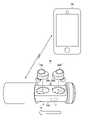
図1は、第一実施形態に係る充電システムの概略を示す斜視図である。充電システム1は、充電ケース10と、左右分離型のワイヤレスイヤホン50とを有する。充電システム1は、充電ケース10のケース用バッテリ17がワイヤレスイヤホン50のイヤホン用バッテリ56を充電する。充電システム1は、充電ケース10がワイヤレスイヤホン50の使用可能時間を予測して、残容量の通知を行う。[First Embodiment]
FIG. 1 is a perspective view showing an outline of a charging system according to the first embodiment. The charging system 1 has a
ここで、ワイヤレスイヤホン50は、分離された左イヤホン50Lと右イヤホン50Rとを有する。以下の説明において、左イヤホン50Lと右イヤホン50Rとの区別を要しない場合、ワイヤレスイヤホン50として説明する。また、イヤホン用バッテリ56は、左イヤホン用バッテリ(以下、「左バッテリ」という。)56Lと右イヤホン用バッテリ(以下、「右バッテリ」という。)56Rとを含む。以下の説明において、左バッテリ56Lと右バッテリ56Rとの区別を要しない場合、イヤホン用バッテリ56として説明する。 Here, the
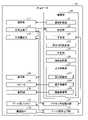
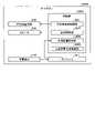
さらに、図2を用いて、充電ケース10について説明する。図2は、第一実施形態に係る充電ケース10の構成例を示すブロック図である。充電ケース10は、ワイヤレスイヤホン50を収容可能なケースである。充電ケース10は、ワイヤレスイヤホン50を収容した状態で充電する。充電ケース10は、筐体10Hと、通信部11と、表示部12と、スピーカ13と、振動部14と、左イヤホン用充電端子(以下、「左充電端子」という。)15と、右イヤホン用充電端子(以下、「右充電端子」という。)16と、ケース用バッテリ17と、電源端子18と、ケース用充電回路21と、イヤホン用充電回路(充電回路)22と、制御部(充電制御装置)30とを有する。 Further, the
筐体10Hは、充電ケース10の外形を規定する。筐体10Hは、ワイヤレスイヤホン50を着脱可能である。より詳しくは、筐体10Hは、内部にワイヤレスイヤホン50を収容可能である。本実施形態は、筐体10Hは、円筒状に形成されている。筐体10Hには、通信部11と表示部12とスピーカ13と振動部14と左充電端子15と右充電端子16とケース用バッテリ17と電源端子18とケース用充電回路21とイヤホン用充電回路22と制御部30とが配置されている。 The
通信部11は、通信ユニットである。通信部11は、ワイヤレスイヤホン50および携帯用電子機器100とデータを送受信可能に接続する。通信部11は、例えば、Bluetooth、または、NFMI(Near Field Magnetic Induction)を含む近距離無線通信や近距離電磁誘導が可能である。本実施形態では、通信部11は、ワイヤレスイヤホン50と、Bluetooth接続によってペアリング可能である。本実施形態では、通信部11は、携帯用電子機器100と、Bluetooth接続によってペアリング可能である。 The communication unit 11 is a communication unit. The communication unit 11 is connected to the
表示部12は、イヤホン用バッテリ56の残容量に関する通知を表示する。表示部12は、液晶ディスプレイ(LCD:Liquid Crystal Display)または有機EL(Organic Electro-Luminescence)ディスプレイなどを含むディスプレイである。本実施形態では、表示部12は、筐体10Hの外周面に配置されている。表示部12は、出力制御部37の表示制御部371から出力された表示信号に基づいて、情報を表示する。 The display unit 12 displays a notification regarding the remaining capacity of the
スピーカ13は、イヤホン用バッテリ56の残容量に関する通知の音声を出力する。スピーカ13は、出力制御部37の音声制御部372から出力された音声信号に基づいて、音声を表示する。スピーカ13は、筐体10Hの外周に配置されている。 The
振動部14は、イヤホン用バッテリ56の残容量に関する通知を示す振動を発生させる。振動部14は、出力制御部37の振動制御部373から出力された制御信号に基づいて、振動を発生させる。 The vibration unit 14 generates vibration indicating a notification regarding the remaining capacity of the
左充電端子15は、ワイヤレスイヤホン50の左イヤホン50Lの左充電端子57L(図3参照)が接続可能な端子である。左充電端子15は、イヤホン用充電回路22を介して、ケース用バッテリ17と接続されている。左充電端子15は、左充電端子57Lを介して、ケース用バッテリ17から左イヤホン50Lの左バッテリ56Lへ充電電流を供給する。左充電端子15は、筐体10Hの内周面に配置されている。 The left charging terminal 15 is a terminal to which the left charging terminal 57L (see FIG. 3) of the
右充電端子16は、ワイヤレスイヤホン50の右イヤホン50Rの右充電端子57R(図4参照)が接続可能な端子である。右充電端子16は、イヤホン用充電回路22を介して、ケース用バッテリ17と接続されている。右充電端子16は、右充電端子57Rを介して、ケース用バッテリ17から右イヤホン50Rの右バッテリ56Rへ充電電流を供給する。右充電端子16は、筐体10Hの内周面に配置されている。 The
ケース用バッテリ17は、ワイヤレスイヤホン50のイヤホン用バッテリ56を充電する。ケース用バッテリ17は、ケース用充電回路21とイヤホン用充電回路22とに接続されている。ケース用バッテリ17は、繰り返し充放電を実行可能な充電池である。ケース用バッテリ17は、例えば、ニッケル水素充電池、リチウムイオン充電池またはリチウムポリマー充電池である。ケース用バッテリ17は、筐体10Hに内蔵されている。 The
電源端子18は、交流電源(商用電源)または直流電源と接続可能である。電源端子18は、ケース用充電回路21に接続されている。電源端子18は、交流電源から供給された交流、または、モバイルバッテリなどの直流電源から供給された直流をケース用充電回路21へ出力する。 The
ケース用充電回路21は、ケース用バッテリ17を充電する充電回路である。ケース用充電回路21は、ケース用バッテリ17と電源端子18とに接続されている。ケース用充電回路21は、電源端子18に交流電源が接続されている場合、電源端子18を介して入力された交流をケース用バッテリ17の充電に適した直流に変換して、ケース用バッテリ17へ供給する。ケース用充電回路21は、電源端子18に直流電源が接続されている場合、電源端子18を介して入力された直流をケース用バッテリ17へ供給する。 The
イヤホン用充電回路22は、ワイヤレスイヤホン50のイヤホン用バッテリ56を充電する充電回路である。イヤホン用充電回路22は、ケース用バッテリ17と左充電端子15と右充電端子16と予測部33とに接続されている。イヤホン用充電回路22は、ケース用バッテリ17から出力された直流をイヤホン用バッテリ56の充電に適した直流に変換して、左充電端子15と右充電端子16とを介してイヤホン用バッテリ56へ供給する。 The
制御部30は、例えば、CPU(Central Processing Unit)などで構成された演算処理装置である。制御部30は、図示しない記憶部に記憶されているプログラムをメモリにロードして、プログラムに含まれる命令を実行する。制御部30には図示しない内部メモリが含まれ、データの一時記憶などに用いられる。制御部30は、通信制御部31と、検出部32と、予測部33と、通知時間設定部34と、判定部35と、通知選択部36と、出力制御部37とを有する。 The
通信制御部31は、通信部11を制御することで、ワイヤレスイヤホン50または携帯用電子機器100と無線通信を行う。 The
検出部32は、筐体10Hへのワイヤレスイヤホン50の着脱状態を検出する。検出部32は、左充電端子15と左イヤホン50Lとの電気的な接続状態、および、右充電端子16と右イヤホン50Rとの電気的な接続状態に基づいて、着脱状態を検出する。検出部32は、左充電端子15と左イヤホン50Lとが電気的に接続され、右充電端子16と右イヤホン50Rとが電気的に接続されている場合、筐体10Hへワイヤレスイヤホン50が取り付けられた状態であることを検出する。検出部32は、左充電端子15と左イヤホン50Lとが電気的に接続されていない、または、右充電端子16と右イヤホン50Rとが電気的に接続されていない場合、筐体10Hからワイヤレスイヤホン50が取り外された状態であることを検出する。 The
検出部32は、筐体10Hへのワイヤレスイヤホン50の着脱状態を、他の方法によって検出してもよい。例えば、検出部32は、筐体10Hへのワイヤレスイヤホン50の着脱によって可動する可動部材の動作に基づいて着脱状態を検出してもよい。検出部32は、筐体10Hへのワイヤレスイヤホン50の着脱を検出するセンサの検出結果に基づいて着脱状態を検出してもよい。例えば、検出部32は、ワイヤレスイヤホン50から取得した使用状態を表す使用情報が音楽データを再生していることを示す場合、ワイヤレスイヤホン50が取り外されていることを検出してもよい。 The
予測部33は、ワイヤレスイヤホン50のイヤホン用バッテリ56の使用可能時間を予測する。より詳しくは、予測部33は、ワイヤレスイヤホン50のイヤホン用バッテリ56の充電時、イヤホン用充電回路22から充電電流と充電時間とを含む充電情報を取得する。そして、予測部33は、イヤホン用充電回路22から取得した充電情報に基づいて、イヤホン用バッテリ56の残容量を算出して、残容量から使用可能時間を予測する。なお、イヤホン用バッテリ56の残容量と使用可能時間との関係は、あらかじめ記憶部に記憶されている。または、予測部33は、筐体10Hにワイヤレスイヤホン50が取り付けられた状態において、左充電端子15または右充電端子16からイヤホン用バッテリ56の電圧の情報を取得して、イヤホン用バッテリ56の電圧から使用可能時間を予測してもよい。なお、イヤホン用バッテリ56の電圧と使用可能時間との関係は、あらかじめ記憶部に記憶されている。 The
通知時間設定部34は、予測部33が予測した使用可能時間に基づいて、残容量の通知を行う時間を設定する。より詳しくは、通知時間設定部34は、使用可能時間の所定時間前を残容量の通知を行う時間に設定する。例えば、通知時間設定部34は、使用可能時間が「180分」である場合、使用可能時間の「30分前」である「150分後」を残容量の通知を行う時間に設定する。または、通知時間設定部34は、使用可能時間に所定割合を乗算した時間を残容量の通知を行う時間に設定してもよい。例えば、通知時間設定部34は、使用可能時間が「100分」である場合、「0.8」を乗算した「80分後」を残容量の通知を行う時間に設定してもよい。 The notification
判定部35は、検出部32がワイヤレスイヤホン50が筐体10Hから取り外し状態であることを検出した場合、予測部33の予測結果に基づいて、イヤホン用バッテリ56の残容量を通知する時間に到達したかを判定する。判定部35は、検出部32の検出結果が示すワイヤレスイヤホン50の状態が、装着状態から取り外し状態に変わったときからの経過時間、言い換えると、ワイヤレスイヤホン50を取り外したときからの経過時間が残容量を通知する時間に到達したかを判定する。 When the
通知選択部36は、判定部35が残容量を通知する時間に到達したと判定した場合、イヤホン用バッテリ56の残容量を通知する通知方法を選択する。より詳しくは、通知選択部36は、ワイヤレスイヤホン50から取得した音楽データの再生状態を示す再生情報を含む使用情報が示す使用状態に応じて、表示によって通知する方法、音声によって通知する方法、または、振動によって通知する方法のうち1つ以上の通知方法を選択する。例えば、通知選択部36は、使用情報がワイヤレスイヤホン50が音楽データを再生していることを示す場合、表示によって通知する方法、および、振動によって通知する方法を選択する。例えば、通知選択部36は、使用情報がワイヤレスイヤホン50が音楽データを再生していないことを示す場合、音声によって通知する方法を選択する。 When the determination unit 35 determines that the time for notifying the remaining capacity has been reached, the notification selection unit 36 selects a notification method for notifying the remaining capacity of the
さらに、通知選択部36は、検出部32の検出結果に応じて、残容量の通知を、充電ケース10、ワイヤレスイヤホン50、または、携帯用電子機器100のいずれが行うかを選択してもよい。通知選択部36は、ワイヤレスイヤホン50が取り外し状態であり、ワイヤレスイヤホン50の残容量がゼロである場合、残容量の通知を充電ケース10または携帯用電子機器100が行う通知方法を選択する。通知選択部36は、ワイヤレスイヤホン50が取り外し状態であり、ワイヤレスイヤホン50の残容量がゼロより大きい場合、残容量の通知をワイヤレスイヤホン50が行う通知方法を選択する。通知選択部36は、残容量の通知を充電ケース10が行う通知方法を選択した場合、出力制御部37に、残容量の通知を実行させる。通知選択部36は、残容量の通知を携帯用電子機器100またはワイヤレスイヤホン50が行う通知方法を選択した場合、通信制御部31を介して、携帯用電子機器100またはワイヤレスイヤホン50に残容量の通知を実行させる制御信号を出力する。 Further, the notification selection unit 36 may select whether the charging
出力制御部37は、判定部35がイヤホン用バッテリ56の残容量を通知する時間に到達したと判定し、通知選択部36が充電ケース10から通知する通知方法を選択した場合、イヤホン用バッテリ56の残容量に関する通知を出力する制御を行う。出力制御部37は、通知選択部36が選択した通知方法に基づいて、制御を行う。出力制御部37は、表示制御部371と、音声制御部372と、振動制御部373とを有する。出力制御部37は、通知選択部36が選択した選択方法に従って、表示制御部371、音声制御部372、または、振動制御部373を制御する。 When the
表示制御部371は、通知選択部36が表示によって通知する方法と、充電ケース10が通知する通知方法を選択した場合、通知を示す情報を表示部12で出力する制御を行う。 The display control unit 371 controls the display unit 12 to output information indicating the notification when the notification selection unit 36 selects the method of notifying by display and the charging
音声制御部372は、通知選択部36が音声によって通知する方法と、充電ケース10が通知する通知方法を選択した場合、通知を示す音声をスピーカ13から出力させる制御を行う。 The
振動制御部373は、通知選択部36が振動によって通知する方法と、充電ケース10が通知する通知方法を選択した場合、通知を示す振動を振動部14によって発生させる制御を行う。 The
ワイヤレスイヤホン50は、左イヤホン50Lと右イヤホン50Rとを有する。左イヤホン50Lと右イヤホン50Rとは、例えばBluetooth接続によってペアリングされている。 The
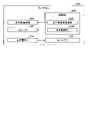
図3を用いて、左イヤホン50Lについて説明する。図3は、第一実施形態に係る左イヤホンの構成例を示すブロック図である。左イヤホン50Lは、左耳用のイヤホンである。左イヤホン50Lは、携帯用電子機器100から音楽データを取得する。左イヤホン50Lは、音楽データの左チャンネルデータをスピーカ54Lから出力する。左イヤホン50Lは、音楽データの右チャンネルデータを右イヤホン50Rへ出力する。左イヤホン50Lは、通信部51Lと、左右用通信部52Lと、発光部53Lと、スピーカ54Lと、振動部55Lと、左バッテリ56Lと、左充電端子57Lと、制御部60Lとを有する。 The
通信部51Lは、通信ユニットである。通信部51Lは、携帯用電子機器100とデータを送受信可能に接続する。本実施形態では、通信部51Lは、携帯用電子機器100から、音楽データを含むデータを受信する。通信部51Lは、例えば、Bluetooth、または、NFMIを含む近距離無線通信や近距離電磁誘導が可能である。本実施形態では、通信部51Lは、携帯用電子機器100と、Bluetooth接続によってペアリング可能である。 The
左右用通信部52Lは、通信ユニットである。左右用通信部52Lは、右イヤホン50Rとデータを送受信可能に接続する。本実施形態では、左右用通信部52Lは、携帯用電子機器100から受信した音楽データのうち、右チャンネルデータを右イヤホン50Rへ送信する。左右用通信部52Lは、例えば、Bluetoothを含む近距離無線通信が可能である。通信部51Lは、右イヤホン50Rと、Bluetooth接続によってペアリング可能である。 The left /
発光部53Lは、イヤホン用バッテリ56の残容量を発光によって表示する。発光部53Lは、例えばLED(Light Emitting Diode)である。発光部53Lは、本実施形態では、左イヤホン50Lの外周面に配置されている。発光部53Lは、出力制御部63Lの発光制御部631Lから出力された制御信号に基づいて、発光したり発光を停止したりする。 The
スピーカ54Lは、左耳において視聴させる音声を出力する。スピーカ54Lは、出力制御部63Lの音声制御部632Lにおいて、音楽データの左チャンネルデータをD/A変換して得られた電気信号を音に変換して出力する。また、スピーカ54Lは、音声制御部632Lから出力された、イヤホン用バッテリ56の残容量に関する通知の音声を出力する。 The
振動部55Lは、イヤホン用バッテリ56の残容量に関する通知を示す振動を発生させる。振動部55Lは、出力制御部63Lの振動制御部633Lから出力された制御信号に基づいて、振動を発生させる。 The
左バッテリ56Lは、左イヤホン50Lが動作するための電力を供給する。左バッテリ56Lは、左充電端子57Lと接続されている。左バッテリ56Lは、繰り返し充放電を実行可能な電池である。左バッテリ56Lは、例えば、ニッケル水素充電池、リチウムイオン充電池またはリチウムポリマー充電池である。左バッテリ56Lは、左イヤホン50Lに内蔵されている。 The
左充電端子57Lは、充電ケース10の左充電端子15と接続可能な端子である。左充電端子57Lは、左バッテリ56Lに接続されている。左充電端子57Lは、左充電端子15から供給された充電電流を左バッテリ56Lに供給する。左充電端子57Lは、左イヤホン50Lの外周に配置されている。 The left charging terminal 57L is a terminal that can be connected to the left charging terminal 15 of the charging
制御部60Lは、例えば、CPU(Central Processing Unit)などで構成された演算処理装置である。制御部60Lは、図示しない記憶部に記憶されているプログラムをメモリにロードして、プログラムに含まれる命令を実行する。制御部60Lには図示しない内部メモリが含まれ、データの一時記憶などに用いられる。制御部60Lは、通信制御部61Lと、左右用通信制御部62Lと、出力制御部63Lとを有する。 The
通信制御部61Lは、通信部51Lを制御することで、携帯用電子機器100及び充電ケース10と無線通信を行う。 The
左右用通信制御部62Lは、左右用通信部52Lを制御することで、右イヤホン50Rと無線通信を行う。 The left / right
出力制御部63Lは、左イヤホン50Lにおける出力を制御する。より詳しくは、出力制御部63Lは、左イヤホン50Lにおいて、音楽データを音として出力する制御を行う。また、出力制御部63Lは、ワイヤレスイヤホン50において、イヤホン用バッテリ56の残容量に関する通知を出力する制御を行う。出力制御部63Lは、発光制御部631Lと、音声制御部632Lと、振動制御部633Lとを有する。 The
発光制御部631Lは、発光部53Lの発光と発光の停止とを制御する。発光制御部631Lは、通知選択部36が表示によって通知する方法と、ワイヤレスイヤホン50が通知する通知方法を選択した場合、発光部53Lを発光させて通知を示す情報を出力する制御を行う。発光制御部631Lは、発光部53Lを発光させた後、所定時間が経過した場合、ユーザが通知を停止する操作を行った場合、または、イヤホン用バッテリ56の充電が開始された場合、発光を停止させる。 The light emission control unit 631L controls the light emission of the
音声制御部632Lは、音楽データの左チャンネルデータをD/A変換して増幅した信号をスピーカ54Lから出力させる。また、音声制御部632Lは、通知選択部36が音声によって通知する方法と、ワイヤレスイヤホン50が通知する通知方法を選択した場合、通知の音声をスピーカ54Lから出力させる制御を行う。音声制御部632Lは、スピーカ54Lから通知の音声を出力した後、所定時間が経過した場合、ユーザが通知を停止する操作を行った場合、または、イヤホン用バッテリ56の充電が開始された場合、通知の音声の出力を停止する。 The
振動制御部633Lは、通知選択部36が振動によって通知する方法と、ワイヤレスイヤホン50が通知する通知方法を選択した場合、通知を示す振動を振動部55Lによって発生させる制御を行う。振動制御部633Lは、振動部55Lを振動させた後、所定時間が経過した場合、ユーザが通知を停止する操作を行った場合、または、イヤホン用バッテリ56の充電が開始された場合、振動を停止させる。 The vibration control unit 633L controls the
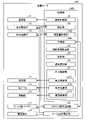
図4を用いて、右イヤホン50Rについて説明する。図4は、第一実施形態に係る右イヤホンの構成例を示すブロック図である。右イヤホン50Rは、右耳用のイヤホンである。右イヤホン50Rは、左イヤホン50Lから音楽データの右チャンネルデータを取得して出力する。右イヤホン50Rは、左右用通信部52Rと、スピーカ54Rと、右バッテリ56Rと、右充電端子57Rと、制御部60Rとを有する。 The
左右用通信部52Rは、通信ユニットである。左右用通信部52Rは、左イヤホン50Lとデータを送受信可能に接続する。本実施形態では、左右用通信部52Rは、左イヤホン50Lから音楽データの右チャンネルデータを受信する。左右用通信部52Rは、例えば、Bluetoothを含む近距離無線通信が可能である。左右用通信部52Rは、左イヤホン50Lと、Bluetooth接続によってペアリング可能である。 The left / right communication unit 52R is a communication unit. The left / right communication unit 52R is connected to the
スピーカ54Rは、右耳において視聴させる音声を出力する。スピーカ54Rは、音声制御部632Rにおいて、音楽データの右チャンネルデータをD/A変換して得られた電気信号を音に変換して出力する。 The
右バッテリ56Rは、右イヤホン50Rが動作するための電力を供給する。右バッテリ56Rは、右充電端子57Rと接続されている。右バッテリ56Rは、繰り返し充放電を実行可能な電池である。右バッテリ56Rは、例えば、ニッケル水素充電池、リチウムイオン充電池またはリチウムポリマー充電池である。右バッテリ56Rは、右イヤホン50Rに内蔵されている。 The
右充電端子57Rは、充電ケース10の右充電端子16と接続可能な端子である。右充電端子57Rは、右バッテリ56Rに接続されている。右充電端子57Rは、右充電端子16から供給された充電電流を右バッテリ56Rに供給する。右充電端子57Rは、右イヤホン50Rの外周に配置されている。 The right charging terminal 57R is a terminal that can be connected to the
制御部60Rは、例えば、CPU(Central Processing Unit)などで構成された演算処理装置である。制御部60Rは、図示しない記憶部に記憶されているプログラムをメモリにロードして、プログラムに含まれる命令を実行する。制御部60Rには図示しない内部メモリが含まれ、データの一時記憶などに用いられる。制御部60Rは、左右用通信制御部62Rと、音声制御部632Rとを有する。 The control unit 60R is, for example, an arithmetic processing unit composed of a CPU (Central Processing Unit) or the like. The control unit 60R loads a program stored in a storage unit (not shown) into a memory and executes an instruction included in the program. The control unit 60R includes an internal memory (not shown), which is used for temporary storage of data and the like. The control unit 60R includes a left / right
左右用通信制御部62Rは、左右用通信部52Rを制御することで、左イヤホン50Lと無線通信を行う。 The left / right
音声制御部632Rは、右イヤホン50Rにおいて、音楽データを音として出力する制御を行う。音声制御部632Rは、音楽データの右チャンネルデータをD/A変換して増幅した信号をスピーカ54Rから出力させる。 The
本実施形態では、ワイヤレスイヤホン50は、左イヤホン50Lが携帯用電子機器100と通信可能な親機であり、右イヤホン50Rが左イヤホン50Lと通信可能な子機であるものとして説明したが、これに限定されない。ワイヤレスイヤホン50は、右イヤホン50Rが親機であり、左イヤホン50Lが子機であってもよく、この場合、左イヤホン50Lと右イヤホン50Rとの構成が上記とは逆になる。 In the present embodiment, the
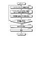
次に、図5を用いて、充電システム1における情報処理について説明する。図5は、第一実施形態に係る充電システムにおける処理の流れを示すフローチャートである。 Next, information processing in the charging system 1 will be described with reference to FIG. FIG. 5 is a flowchart showing a processing flow in the charging system according to the first embodiment.
制御部30は、予測部33によって、イヤホン用バッテリ56の使用可能時間を予測する(ステップS101)。例えば、予測部33は、ワイヤレスイヤホン50のイヤホン用バッテリ56の充電時、イヤホン用充電回路22から取得した充電情報に基づいて、使用可能時間を予測する。制御部30は、ステップS102に進む。 The
制御部30は、検出部32によって、ワイヤレスイヤホン50が充電ケース10から取り外されたかを判定する(ステップS102)。検出部32は、ワイヤレスイヤホン50が充電ケース10から取り外されたと判定する場合(ステップS102でYes)、ステップS103に進む。検出部32は、ワイヤレスイヤホン50が充電ケース10から取り外されていないと判定する場合(ステップS102でNo)、ステップS101の処理を再度実行する。 The
ワイヤレスイヤホン50が充電ケース10から取り外されたと判定する場合(ステップS102でYes)、制御部30は、通知時間設定部34によって、予測部33が予測した使用可能時間に基づいて、残容量の通知を行う時間を設定する(ステップS103)。より詳しくは、制御部30は、通知時間設定部34によって、ワイヤレスイヤホン50が取り外されたときの使用可能時間から残容量の通知を行う時間を設定する。例えば、予測された使用可能時間が「180分」である場合、使用可能時間の「30分前」である「150分後」を残容量の通知を行う時間に設定する。制御部30は、ステップS104に進む。 When it is determined that the
制御部30は、残容量の通知を行う時間に到達したかを判定する(ステップS104)。制御部30は、ワイヤレスイヤホン50が装着状態から取り外し状態に変わったときからの経過時間が残容量の通知を行う時間に到達したと判定する場合(ステップS104でYes)、ステップS105に進む。制御部30は、残容量の通知を行う時間に到達していないと判定する場合(ステップS104でNo)、ステップS103の処理を再度実行する。 The
制御部30は、通知選択部36によって、通知方法を選択する(ステップS105)。より詳しくは、通知選択部36は、ワイヤレスイヤホン50から取得した使用情報が示す使用状態に応じて、表示によって通知する方法、音声によって通知する方法、または、振動によって通知する方法のうち1つ以上の通知方法を選択する。また、通知選択部36は、検出部32の検出結果に応じて、残容量の通知を、充電ケース10、ワイヤレスイヤホン50、または、携帯用電子機器100のいずれが行うかを選択してもよい。制御部30は、ステップS106に進む。 The
制御部30は、残容量を通知する(ステップS106)。より詳しくは、制御部30は、通知選択部36が充電ケース10が通知する通知方法を選択した場合、出力制御部37によって、通知を示す情報を充電ケース10から出力する制御を行う。制御部30は、通知選択部36がワイヤレスイヤホン50が通知する通知方法を選択した場合、出力制御部63Lによって、通知を示す情報を左イヤホン50Lから出力する制御を行う。制御部30は、通知選択部36が携帯用電子機器100が通知する通知方法を選択した場合、通知を示す情報を携帯用電子機器100から出力する制御を行う。 The
制御部30は、残容量の通知を行った後、所定時間が経過した場合、ユーザが通知を停止する操作を行った場合、または、イヤホン用バッテリ56の充電が開始された場合、通知を停止させる。 The
このようにして、充電ケース10は、予測部33によってワイヤレスイヤホン50の使用可能時間を予測する。そして、充電ケース10は、検出部32がワイヤレスイヤホン50が筐体10Hから取り外し状態であることを検出した場合、判定部35によって、残容量の通知時間に到達したかを判定する。そして、充電ケース10は、判定部35が残容量の通知時間に到達したと判定する場合、残容量の通知を行う。 In this way, the charging
本実施形態は、ワイヤレスイヤホン50の使用状態に応じて、表示によって通知する方法、音声によって通知する方法、または、振動によって通知する方法のうち1つ以上の通知方法を選択する。また、本実施形態は、検出部32の検出結果に応じて、残容量の通知を、充電ケース10、ワイヤレスイヤホン50、または、携帯用電子機器100のいずれが行うかを選択可能である。本実施形態によれば、状況に応じて、適切に残容量を通知することができる。これにより、例えば、本実施形態は、ユーザがワイヤレスイヤホン50を使用していないときでも、残容量を通知することができる。例えば、本実施形態は、ユーザがワイヤレスイヤホン50で音楽データを再生を使用しているとき、視聴を妨げずに残容量を通知することができる。 In the present embodiment, one or more notification methods are selected from a method of notifying by display, a method of notifying by voice, and a method of notifying by vibration, depending on the usage state of the
本実施形態は、残容量の通知を充電ケース10のみで行なう構成とすることも可能である。この場合、充電ケース10の通信部11および通信制御部31の構成が不要となり、簡易な構成とすることができる。 In this embodiment, it is also possible to notify the remaining capacity only by the charging
上述したように、本実施形態は、充電ケース10の予測部33によってワイヤレスイヤホン50の使用可能時間を予測する。そして、本実施形態は、充電ケース10の検出部32がワイヤレスイヤホン50が筐体10Hから取り外し状態であることを検出した場合、判定部35によって、残容量の通知時間に到達したかを判定する。このようにして、本実施形態は、充電ケースの判定部35が残容量の通知時間に到達したと判定する場合、残容量の通知を行うことができる。本実施形態によれば、ワイヤレスイヤホン50の電源が入っていないときでも、残容量の通知を行うことができる。本実施形態は、ワイヤレスイヤホン50の充電し忘れを抑制することができる。 As described above, in the present embodiment, the
[第二実施形態]
図6、図7を参照しながら、本実施形態に係る充電システム1Aについて説明する。図6は、第二実施形態に係る充電ケースの構成例を示すブロック図である。図7は、第二実施形態に係る充電システムにおける処理の流れを示すフローチャートである。充電システム1Aは、基本的な構成は第一実施形態の充電システム1と同様である。以下の説明においては、充電システム1と同様の構成要素には、同一の符号または対応する符号を付し、その詳細な説明は省略する。充電システム1Aの充電ケース10Aは、制御部30Aが特定部38Aを有する点と、予測部33Aと判定部35Aとにおける処理とが第一実施形態と異なる。[Second Embodiment]
The charging system 1A according to the present embodiment will be described with reference to FIGS. 6 and 7. FIG. 6 is a block diagram showing a configuration example of the charging case according to the second embodiment. FIG. 7 is a flowchart showing a processing flow in the charging system according to the second embodiment. The basic configuration of the charging system 1A is the same as that of the charging system 1 of the first embodiment. In the following description, the same components as those of the charging system 1 are designated by the same reference numerals or corresponding reference numerals, and detailed description thereof will be omitted. The charging case 10A of the charging system 1A is different from the first embodiment in that the
予測部33Aは、ワイヤレスイヤホン50のイヤホン用バッテリ56について、左バッテリ56Lの使用可能時間と、右バッテリ56Rの使用可能時間とをそれぞれ予測する。より詳しくは、予測部33Aは、ワイヤレスイヤホン50のイヤホン用バッテリ56の充電時、イヤホン用充電回路22から、左バッテリ56Lおよび右バッテリ56Rのそれぞれの充電情報を取得する。そして、予測部33Aは、イヤホン用充電回路22から取得した充電情報に基づいて、左バッテリ56Lおよび右バッテリ56Rの残容量をそれぞれ算出して、残容量から使用可能時間をぞれぞれ予測する。または、予測部33Aは、筐体10Hにワイヤレスイヤホン50が取り付けられた状態において、左充電端子15および右充電端子16からイヤホン用バッテリ56の電圧の情報をそれぞれ取得して、左バッテリ56Lおよび右バッテリ56Rの電圧から使用可能時間をそれぞれ予測してもよい。 The prediction unit 33A predicts the usable time of the
特定部38Aは、予測部33Aが予測した使用可能時間に基づいて、イヤホン用バッテリ56の左バッテリ56Lおよび右バッテリ56Rのうち、残容量が少ない方を特定する。 The
判定部35Aは、特定部38Aによって特定された残容量が少ない方についての予測部33Aの予測結果に基づいて、イヤホン用バッテリ56の残容量を通知する時間に到達したかを判定する。 The
次に、図7を用いて、充電システム1Aにおける情報処理について説明する。図7に示すフローチャートのステップS111、ステップS113、ステップS115ないしステップS117は、図5に示すフローチャートのステップS101、ステップS102、ステップS104ないしステップS106と同様の処理を行う。 Next, information processing in the charging system 1A will be described with reference to FIG. 7. Step S111, step S113, and steps S115 to S117 of the flowchart shown in FIG. 7 perform the same processing as steps S101, S102, and steps S104 to S106 of the flowchart shown in FIG.
制御部30Aは、使用可能時間が少ない方を特定する(ステップS112)。より詳しくは、制御部30Aは、特定部38Aによって、予測部33Aの予測結果に基づいて、イヤホン用バッテリ56の左バッテリ56Lおよび右バッテリ56Rのうち、残容量が少ない方を特定する。制御部30Aは、ステップS113に進む。 The
制御部30Aは、通知時間設定部34によって、予測部33Aが予測した、使用可能時間が少ない方の使用可能時間に基づいて、残容量の通知を行う時間を設定する(ステップS114)。制御部30Aは、ステップS115に進む。 The
このようにして、充電ケース10Aがワイヤレスイヤホン50の左バッテリ56Lおよび右バッテリ56Rのそれぞれ使用可能時間を予測して、少ない方の使用可能時間に基づいて、残容量の通知を行う。 In this way, the charging case 10A predicts the usable time of the
上述したように、本実施形態では、充電ケース10Aがワイヤレスイヤホン50の左バッテリ56Lおよび右バッテリ56Rのそれぞれ使用可能時間を予測して、少ない方の使用可能時間に基づいて、残容量の通知を行うことができる。本実施形態によれば、左バッテリ56Lおよび右バッテリ56Rの使用可能時間が異なる場合でも、適切に残容量を通知することができる。 As described above, in the present embodiment, the charging case 10A predicts the usable time of the
[第三実施形態]
図8ないし図12を参照しながら、本実施形態に係る充電システム1Bについて説明する。図8は、第三実施形態に係る充電ケースの構成例を示すブロック図である。図9は、第三実施形態に係る左イヤホンの構成例を示すブロック図である。図10は、第三実施形態に係る右イヤホンの構成例を示すブロック図である。図11は、第三実施形態に係る充電システムにおける処理の流れを示すフローチャートである。図12は、第三実施形態に係る充電システムにおける処理の流れの他の例を示すフローチャートである。充電システム1Bの充電ケース10Bは、制御部30Bが残容量取得部39Bを有する点と、予測部33Bにおける処理とが第一実施形態と異なる。左イヤホン50LBは、制御部60LBが左残容量取得部64LBと残容量送信制御部65LBとを有する点が第一実施形態と異なる。右イヤホン50RBは、制御部60RBが右残容量取得部64RBと右残容量送信制御部65RBとを有する点が第一実施形態と異なる。[Third Embodiment]
The charging system 1B according to the present embodiment will be described with reference to FIGS. 8 to 12. FIG. 8 is a block diagram showing a configuration example of the charging case according to the third embodiment. FIG. 9 is a block diagram showing a configuration example of the left earphone according to the third embodiment. FIG. 10 is a block diagram showing a configuration example of the right earphone according to the third embodiment. FIG. 11 is a flowchart showing a processing flow in the charging system according to the third embodiment. FIG. 12 is a flowchart showing another example of the processing flow in the charging system according to the third embodiment. The charging case 10B of the charging system 1B is different from the first embodiment in that the
残容量取得部39Bは、ワイヤレスイヤホン50からイヤホン用バッテリ56の残容量を示す残容量情報を取得する。本実施形態では、残容量取得部39Bは、左バッテリ56Lおよび右バッテリ56Rのそれぞれの残容量を示す残容量情報を取得する。 The remaining
予測部33Bは、残容量取得部39Bが取得した残容量情報に基づいて、イヤホン用バッテリ56の使用可能時間を予測する。本実施形態では、予測部33Bは、残容量取得部39Bが取得した残容量情報に基づいて、左バッテリ56Lの使用可能時間と、右バッテリ56Rの使用可能時間とをそれぞれ予測する。 The
左残容量取得部64LBは、左バッテリ56Lの残容量を取得する。 The left remaining capacity acquisition unit 64LB acquires the remaining capacity of the
残容量送信制御部65LBは、左残容量取得部64LBが取得した左バッテリ56Lの残容量の情報と、右イヤホン50RBから取得した右バッテリ56Rの残容量の情報とを、充電ケース10Bへ送信する。 The remaining capacity transmission control unit 65LB transmits the information on the remaining capacity of the
右残容量取得部64RBは、右バッテリ56Rの残容量を取得する。 The right remaining capacity acquisition unit 64RB acquires the remaining capacity of the
右残容量送信制御部65RBは、右残容量取得部64RBが取得した右バッテリ56Rの残容量の情報を、左イヤホン50LBへ送信する。 The right remaining capacity transmission control unit 65RB transmits the information on the remaining capacity of the
次に、図11を用いて、充電システム1Bにおける情報処理について説明する。図11に示すフローチャートのステップS123ないしステップS126は、図5に示すフローチャートのステップS103ないしステップS106と同様の処理を行う。 Next, information processing in the charging system 1B will be described with reference to FIG. Steps S123 to S126 of the flowchart shown in FIG. 11 perform the same processing as steps S103 to S106 of the flowchart shown in FIG.
制御部30Bは、残容量取得部39Bによって、ワイヤレスイヤホン50からイヤホン用バッテリ56の残容量を取得する(ステップS121)。より詳しくは、残容量取得部39Bは、左イヤホン50LBの残容量送信制御部65LBから送信された、左バッテリ56Lの残容量の情報と右バッテリ56Rの残容量の情報とを取得する。制御部30Bは、ステップS122に進む。 The
制御部30Bは、予測部33Bによって、ワイヤレスイヤホン50から取得したイヤホン用バッテリ56の残容量の情報に基づいて、イヤホン用バッテリ56の使用可能時間を予測する(ステップS122)。制御部30Bは、ステップS123に進む。 The
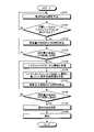
次に、図12を用いて、充電システム1Bにおける情報処理の他の例について説明する。図12に示すフローチャートのステップS131、ステップS132は、図5に示すフローチャートのステップS101、ステップS102と同様の処理を行う。図12に示すフローチャートのステップS135ないしステップS140は、図11に示すフローチャートのステップS121ないしステップS126と同様の処理を行う。 Next, another example of information processing in the charging system 1B will be described with reference to FIG. Step S131 and step S132 of the flowchart shown in FIG. 12 perform the same processing as steps S101 and S102 of the flowchart shown in FIG. Steps S135 to S140 of the flowchart shown in FIG. 12 perform the same processing as steps S121 to S126 of the flowchart shown in FIG.
制御部30Bは、予測部33Bが予測した使用可能時間に基づいて、ワイヤレスイヤホン50から残容量の取得を行う時間を設定する(ステップS133)。より詳しくは、制御部30Bは、ワイヤレスイヤホン50が取り外されたときの使用可能時間から残容量の取得を開始する時間を設定する。例えば、予測された使用可能時間が「180分」である場合、使用可能時間の「60分前」である「120分後」を残容量の取得を開始する時間に設定する。制御部30Bは、ステップS134に進む。 The
制御部30Bは、残容量の取得を開始する時間に到達したかを判定する(ステップS134)。制御部30Bは、ワイヤレスイヤホン50が装着状態から取り外し状態に変わったときからの経過時間が残容量の取得を開始する時間に到達したと判定する場合(ステップS134でYes)、ステップS135に進む。制御部30Bは、残容量の取得を開始する時間に達していないと判定する場合(ステップS134でNo)、ステップS133の処理を再度実行する。 The
このようにして、充電ケース10Bがワイヤレスイヤホン50から取得した残容量の情報に基づいて使用可能時間を予測して、残容量の通知を行う。 In this way, the chargeable case 10B predicts the usable time based on the information on the remaining capacity acquired from the
上述したように、本実施形態では、充電ケース10Bがワイヤレスイヤホン50から取得した残容量の情報に基づいて使用可能時間を予測して、残容量の通知を行うことができる。本実施形態によれば、イヤホン用バッテリ56の使用可能時間をより適切に予測することができる。 As described above, in the present embodiment, the usable time can be predicted based on the information of the remaining capacity acquired from the
本実施形態によれば、ワイヤレスイヤホン50の使用状態に応じて残容量が変化しても、イヤホン用バッテリ56の使用可能時間を適切に予測することができる。 According to the present embodiment, even if the remaining capacity changes according to the usage state of the
本実施形態は、残容量の取得を開始する時間を設定して、残容量の取得を開始する時間に到達した後に、ワイヤレスイヤホン50から残容量の取得を行うことができる。本実施形態によれば、ワイヤレスイヤホン50から残容量の取得を行うためのデータの送受信の回数を抑制することができる。 In this embodiment, the time for starting the acquisition of the remaining capacity is set, and after the time for starting the acquisition of the remaining capacity is reached, the remaining capacity can be acquired from the
図示した充電システム1の各構成要素は、機能概念的なものであり、必ずしも物理的に図示の如く構成されていなくてもよい。すなわち、各装置の具体的形態は、図示のものに限られず、各装置の処理負担や使用状況などに応じて、その全部または一部を任意の単位で機能的または物理的に分散または統合してもよい。 Each component of the illustrated charging system 1 is functionally conceptual and does not necessarily have to be physically configured as shown. That is, the specific form of each device is not limited to the one shown in the figure, and all or part of the device is functionally or physically dispersed or integrated in an arbitrary unit according to the processing load and usage status of each device. You may.
充電システム1の構成は、例えば、ソフトウェアとして、メモリにロードされたプログラムなどによって実現される。上記実施形態では、これらのハードウェアまたはソフトウェアの連携によって実現される機能ブロックとして説明した。すなわち、これらの機能ブロックについては、ハードウェアのみ、ソフトウェアのみ、または、それらの組み合わせによって種々の形で実現できる。 The configuration of the charging system 1 is realized, for example, by a program loaded in a memory as software. In the above embodiment, it has been described as a functional block realized by cooperation of these hardware or software. That is, these functional blocks can be realized in various forms by hardware only, software only, or a combination thereof.
上記に記載した構成要素には、当業者が容易に想定できるもの、実質的に同一のものを含む。さらに、上記に記載した構成は適宜組み合わせが可能である。また、本発明の要旨を逸脱しない範囲において構成の種々の省略、置換または変更が可能である。 The components described above include those easily assumed by those skilled in the art and substantially the same. Further, the configurations described above can be combined as appropriate. Further, various omissions, substitutions or changes of the configuration can be made without departing from the gist of the present invention.
上記では、イヤホン用バッテリ56は、充電ケース10と端子によって電気的に接続された状態で充電するものとして説明したが、非接触充電であってもよい。 In the above, the
第三実施形態では、右イヤホン50RBが右バッテリ56Rの残容量の情報を左イヤホン50LBへ送信して、左イヤホン50LBが左バッテリ56Lの残容量の情報と右バッテリ56Rの残容量の情報とを充電ケース10Bへ送信するものとして説明したが、これに限定されない。右イヤホン50RBが右バッテリ56Rの残容量の情報を充電ケース10Bへ直接送信するようにしてもよい。 In the third embodiment, the right earphone 50RB transmits information on the remaining capacity of the
さらに、制御部30は、充電ケース10のケース用バッテリ17の残容量を取得して、ケース用バッテリ17の残容量を通知するようにしてもよい。例えば、図5に示すフローチャートのステップS102でYesと判定された後で、ステップS103の処理を実行する前に、ケース用バッテリ17の残容量が所定値以下である場合、ケース用バッテリ17の残容量を通知してから、ステップS103の処理を実行してもよい。これにより、ケース用バッテリ17の充電し忘れを抑制することができる。 Further, the
1 充電システム
10 充電ケース
10H 筐体
17 ケース用バッテリ
21 ケース用充電回路
22 イヤホン用充電回路(充電回路)
30 制御部(充電制御装置)
32 検出部
33 予測部
34 通知時間設定部
35 判定部
36 通知選択部
37 出力制御部
50 ワイヤレスイヤホン
50L 左イヤホン
56L 左バッテリ
60L 制御部
50R 右イヤホン
56R 右バッテリ
60R 制御部1 Charging
30 Control unit (charge control device)
32
Claims (8)
Translated fromJapanese前記筐体に配置されたケース用バッテリによって充電される前記ワイヤレスイヤホンのイヤホン用バッテリの使用可能時間を予測する予測部と、
前記検出部が前記ワイヤレスイヤホンが前記筐体から取り外し状態であることを検出した場合、前記予測部の予測結果に基づいて、前記イヤホン用バッテリの残容量を通知する時間に到達したかを判定する判定部と、
前記判定部が前記イヤホン用バッテリの残容量を通知する時間に到達したと判定した場合、前記イヤホン用バッテリの残容量に関する通知を出力する制御を行う出力制御部と、
を備えることを特徴とする充電制御装置。A detection unit that detects the attachment / detachment state of the wireless earphone to the detachable housing of the wireless earphone, and
A predictor that predicts the usable time of the earphone battery of the wireless earphone charged by the case battery arranged in the housing, and
When the detection unit detects that the wireless earphone is in the removed state from the housing, it is determined whether or not the time for notifying the remaining capacity of the earphone battery has been reached based on the prediction result of the prediction unit. Judgment unit and
When the determination unit determines that the time for notifying the remaining capacity of the earphone battery has been reached, an output control unit that controls to output a notification regarding the remaining capacity of the earphone battery, and an output control unit.
A charge control device characterized by being equipped with.
前記筐体に配置され、前記ワイヤレスイヤホンのイヤホン用バッテリを充電するケース用バッテリと、
前記ケース用バッテリから供給される電力によって前記イヤホン用バッテリを充電する充電回路と、
前記筐体へのワイヤレスイヤホンの着脱状態を検出する検出部と、
前記イヤホン用バッテリの使用可能時間を予測する予測部と、
前記検出部が前記ワイヤレスイヤホンが前記筐体から取り外し状態であることを検出した場合、前記予測部の予測結果に基づいて、前記イヤホン用バッテリの残容量を通知する時間に到達したかを判定する判定部と、
前記判定部が前記イヤホン用バッテリの残容量を通知する時間に到達したと判定した場合、前記イヤホン用バッテリの残容量に関する通知を出力する制御を行う出力制御部と、
を備えることを特徴とする充電ケース。With a detachable housing for wireless earphones,
A case battery arranged in the housing and charging the earphone battery of the wireless earphone,
A charging circuit that charges the earphone battery with the electric power supplied from the case battery, and
A detection unit that detects the attachment / detachment state of the wireless earphone to the housing, and
A predictor that predicts the usable time of the earphone battery,
When the detection unit detects that the wireless earphone is in the removed state from the housing, it is determined whether or not the time for notifying the remaining capacity of the earphone battery has been reached based on the prediction result of the prediction unit. Judgment unit and
When the determination unit determines that the time for notifying the remaining capacity of the earphone battery has been reached, an output control unit that controls to output a notification regarding the remaining capacity of the earphone battery, and an output control unit.
A charging case characterized by being equipped with.
を備え、
前記判定部は、前記特定部によって特定された残容量が少ない方についての前記予測部の予測結果に基づいて、前記イヤホン用バッテリの残容量を通知する時間に到達したかを判定する、
請求項2に記載の充電ケース。A specific part that specifies which of the left earphone battery and the right earphone battery of the earphone battery has the smaller remaining capacity.
Equipped with
The determination unit determines whether or not the time for notifying the remaining capacity of the earphone battery has been reached based on the prediction result of the prediction unit for the one with the smaller remaining capacity specified by the specific unit.
The charging case according to claim 2.
を備え、
前記予測部は、前記残容量取得部が取得した前記残容量に基づいて、予測する、
請求項2または3に記載の充電ケース。Remaining capacity acquisition unit that acquires the remaining capacity from the earphone battery,
Equipped with
The prediction unit predicts based on the remaining capacity acquired by the remaining capacity acquisition unit.
The charging case according to claim 2 or 3.
を備え、
前記出力制御部は、前記通知選択部が選択した通知方法に基づいて、制御を行う、
請求項2から4のいずれか一項に記載の充電ケース。A notification selection unit that selects a notification method for notification regarding the remaining capacity of the earphone battery based on the playback information of music data in the wireless earphone.
Equipped with
The output control unit controls based on the notification method selected by the notification selection unit.
The charging case according to any one of claims 2 to 4.
前記ワイヤレスイヤホンと、
を備えることを特徴とする充電システム。The charging case according to any one of claims 2 to 5.
With the wireless earphone
A charging system characterized by being equipped with.
前記筐体に配置されたケース用バッテリによって充電される前記ワイヤレスイヤホンのイヤホン用バッテリの使用可能時間を予測する予測ステップと、
前記検出ステップによって前記ワイヤレスイヤホンが前記筐体から取り外し状態であることが検出された場合、前記予測ステップにおける予測結果に基づいて、前記イヤホン用バッテリの残容量を通知する時間に到達したかを判定する判定ステップと、
前記判定ステップによって前記イヤホン用バッテリの残容量を通知する時間に到達したと判定された場合、前記イヤホン用バッテリの残容量に関する通知を出力する制御を行う出力制御ステップと、
を含む充電制御方法。A detection step for detecting the attachment / detachment state of the wireless earphone to the detachable housing of the wireless earphone, and
A prediction step for predicting the usable time of the earphone battery of the wireless earphone charged by the case battery arranged in the housing, and
When it is detected by the detection step that the wireless earphone is removed from the housing, it is determined whether the time for notifying the remaining capacity of the earphone battery has been reached based on the prediction result in the prediction step. Judgment step to do and
When it is determined by the determination step that the time for notifying the remaining capacity of the earphone battery has been reached, an output control step for controlling to output a notification regarding the remaining capacity of the earphone battery, and an output control step.
Charge control methods including.
前記筐体に配置されたケース用バッテリによって充電される前記ワイヤレスイヤホンのイヤホン用バッテリの使用可能時間を予測する予測ステップと、
前記検出ステップによって前記ワイヤレスイヤホンが前記筐体から取り外し状態であることが検出された場合、前記予測ステップにおける予測結果に基づいて、前記イヤホン用バッテリの残容量を通知する時間に到達したかを判定する判定ステップと、
前記判定ステップによって前記イヤホン用バッテリの残容量を通知する時間に到達したと判定された場合、前記イヤホン用バッテリの残容量に関する通知を出力する制御を行う出力制御ステップと、
を充電制御装置として動作するコンピュータに実行させるためのプログラム。A detection step for detecting the attachment / detachment state of the wireless earphone to the detachable housing of the wireless earphone, and
A prediction step for predicting the usable time of the earphone battery of the wireless earphone charged by the case battery arranged in the housing, and
When it is detected by the detection step that the wireless earphone is removed from the housing, it is determined whether the time for notifying the remaining capacity of the earphone battery has been reached based on the prediction result in the prediction step. Judgment step to do and
When it is determined by the determination step that the time for notifying the remaining capacity of the earphone battery has been reached, an output control step for controlling to output a notification regarding the remaining capacity of the earphone battery, and an output control step.
A program to run a computer that operates as a charge control device.
Priority Applications (1)
| Application Number | Priority Date | Filing Date | Title |
|---|---|---|---|
| JP2018243456AJP7052711B2 (en) | 2018-12-26 | 2018-12-26 | Charge control device, charging case, charging system, charge control method and program |
Applications Claiming Priority (1)
| Application Number | Priority Date | Filing Date | Title |
|---|---|---|---|
| JP2018243456AJP7052711B2 (en) | 2018-12-26 | 2018-12-26 | Charge control device, charging case, charging system, charge control method and program |
Publications (2)
| Publication Number | Publication Date |
|---|---|
| JP2020108223A JP2020108223A (en) | 2020-07-09 |
| JP7052711B2true JP7052711B2 (en) | 2022-04-12 |
Family
ID=71449589
Family Applications (1)
| Application Number | Title | Priority Date | Filing Date |
|---|---|---|---|
| JP2018243456AActiveJP7052711B2 (en) | 2018-12-26 | 2018-12-26 | Charge control device, charging case, charging system, charge control method and program |
Country Status (1)
| Country | Link |
|---|---|
| JP (1) | JP7052711B2 (en) |
Families Citing this family (6)
| Publication number | Priority date | Publication date | Assignee | Title |
|---|---|---|---|---|
| CN111757212B (en)* | 2020-07-29 | 2022-06-21 | 歌尔科技有限公司 | Earphone box and audio assembly |
| CN115885479A (en)* | 2021-01-20 | 2023-03-31 | 辉达公司 | Techniques to perform data decoding of wireless communication signals |
| CN113286215B (en)* | 2021-02-07 | 2024-06-04 | 珠海市杰理科技股份有限公司 | Wireless earphone and control method thereof, and earphone system |
| CN113391692A (en)* | 2021-06-11 | 2021-09-14 | 上海明略人工智能(集团)有限公司 | Electric quantity prompting method, device and system of recording equipment |
| US12228644B2 (en) | 2021-11-16 | 2025-02-18 | Samsung Electronics Co., Ltd. | Method for sensing wearing of electronic device and electronic device applied the same |
| KR102689094B1 (en)* | 2023-03-16 | 2024-07-26 | 주식회사 엠제이바이오켐 | Wireless Earphone Case with Anti-loss Function for Smart-Phone |
Citations (9)
| Publication number | Priority date | Publication date | Assignee | Title |
|---|---|---|---|---|
| JP2001016791A (en) | 1999-06-25 | 2001-01-19 | Casio Comput Co Ltd | Charging device |
| JP2001176562A (en) | 1999-12-20 | 2001-06-29 | Hitachi Maxell Ltd | Notification method for running out of battery in mobile devices |
| JP2004152648A (en) | 2002-10-31 | 2004-05-27 | Victor Co Of Japan Ltd | Battery remaining power notifying device |
| JP2009207281A (en) | 2008-02-27 | 2009-09-10 | Kyocera Corp | Electronics |
| JP2011205851A (en) | 2010-03-26 | 2011-10-13 | Ntt Docomo Inc | Electronic apparatus and notification control method |
| JP2013051626A (en) | 2011-08-31 | 2013-03-14 | Sony Corp | Earphone apparatus |
| JP2014003835A (en) | 2012-06-20 | 2014-01-09 | Nikon Corp | Electronic apparatus, power control system, and power control unit |
| US20170064429A1 (en) | 2015-08-29 | 2017-03-02 | Bragi GmbH | Smart Case Power Utilization Control System and Method |
| JP2017099259A (en) | 2015-09-30 | 2017-06-01 | アップル インコーポレイテッド | Case for charging and holding portable listening devices |
Family Cites Families (1)
| Publication number | Priority date | Publication date | Assignee | Title |
|---|---|---|---|---|
| JPH0743439A (en)* | 1994-03-14 | 1995-02-14 | Olympus Optical Co Ltd | Battery remaining computing apparatus |
- 2018
- 2018-12-26JPJP2018243456Apatent/JP7052711B2/enactiveActive
Patent Citations (9)
| Publication number | Priority date | Publication date | Assignee | Title |
|---|---|---|---|---|
| JP2001016791A (en) | 1999-06-25 | 2001-01-19 | Casio Comput Co Ltd | Charging device |
| JP2001176562A (en) | 1999-12-20 | 2001-06-29 | Hitachi Maxell Ltd | Notification method for running out of battery in mobile devices |
| JP2004152648A (en) | 2002-10-31 | 2004-05-27 | Victor Co Of Japan Ltd | Battery remaining power notifying device |
| JP2009207281A (en) | 2008-02-27 | 2009-09-10 | Kyocera Corp | Electronics |
| JP2011205851A (en) | 2010-03-26 | 2011-10-13 | Ntt Docomo Inc | Electronic apparatus and notification control method |
| JP2013051626A (en) | 2011-08-31 | 2013-03-14 | Sony Corp | Earphone apparatus |
| JP2014003835A (en) | 2012-06-20 | 2014-01-09 | Nikon Corp | Electronic apparatus, power control system, and power control unit |
| US20170064429A1 (en) | 2015-08-29 | 2017-03-02 | Bragi GmbH | Smart Case Power Utilization Control System and Method |
| JP2017099259A (en) | 2015-09-30 | 2017-06-01 | アップル インコーポレイテッド | Case for charging and holding portable listening devices |
Also Published As
| Publication number | Publication date |
|---|---|
| JP2020108223A (en) | 2020-07-09 |
Similar Documents
| Publication | Publication Date | Title |
|---|---|---|
| JP7052711B2 (en) | Charge control device, charging case, charging system, charge control method and program | |
| DK2672731T3 (en) | Hearing instrument system with rechargeable battery | |
| US8295532B2 (en) | Method and system for wireless headset instant on capability during battery charging | |
| CN113475051B (en) | Apparatus and method for providing user interface according to wireless power sharing | |
| US10150029B2 (en) | Vibrating apparatus and vibrating method | |
| US11658703B2 (en) | Electronic device and method for wired and wireless charging in electronic device | |
| JP2009065347A (en) | Wireless headphone system | |
| CN112653956B (en) | Earphone box, earphone device, mobile terminal and charging method for wireless earphone | |
| JP2016052186A (en) | Charging type electric apparatus | |
| EP3702885B1 (en) | Method of controlling charging of battery and electronic device to which the method is applied | |
| KR20200101175A (en) | Electronic device for wireless charging external device | |
| KR20220022707A (en) | Audio output device and method for transmitting information about charging status of audio output device | |
| JP6185396B2 (en) | Wearable small electrical equipment | |
| CN112653957A (en) | Earphone box, earphone device, mobile terminal and charging method of wireless earphone | |
| US9219371B2 (en) | Apparatus and method for charging a battery pack | |
| US20150125017A1 (en) | Hearing device using multiple batteries and method of managing power of hearing device | |
| WO2023020322A1 (en) | Wireless earphone, earphone case and wireless earphone system | |
| CN111342506B (en) | Charging technique for series-connected batteries | |
| CN114503390A (en) | Method for controlling charging of battery of electronic device and electronic device thereof | |
| CN212909978U (en) | Earphone wearing detection structure and supra-aural earphone | |
| KR101188358B1 (en) | Apparatus of controlling a power of a electronic device without power-off and the controlling method thereof | |
| JP2021016292A (en) | Electronic apparatus and charging system of the same | |
| JP2020108311A (en) | Charger | |
| EP4062653B1 (en) | Method of operating a hearing assistive device having a rechargeable battery | |
| JP2004040845A (en) | Battery pack, and electric equipment with battery pack |
Legal Events
| Date | Code | Title | Description |
|---|---|---|---|
| A621 | Written request for application examination | Free format text:JAPANESE INTERMEDIATE CODE: A621 Effective date:20210226 | |
| A977 | Report on retrieval | Free format text:JAPANESE INTERMEDIATE CODE: A971007 Effective date:20220222 | |
| TRDD | Decision of grant or rejection written | ||
| A01 | Written decision to grant a patent or to grant a registration (utility model) | Free format text:JAPANESE INTERMEDIATE CODE: A01 Effective date:20220301 | |
| A61 | First payment of annual fees (during grant procedure) | Free format text:JAPANESE INTERMEDIATE CODE: A61 Effective date:20220314 | |
| R150 | Certificate of patent or registration of utility model | Ref document number:7052711 Country of ref document:JP Free format text:JAPANESE INTERMEDIATE CODE: R150 |