JP7047300B2 - Medium cooling member and image forming device - Google Patents
Medium cooling member and image forming deviceDownload PDFInfo
- Publication number
- JP7047300B2 JP7047300B2JP2017181516AJP2017181516AJP7047300B2JP 7047300 B2JP7047300 B2JP 7047300B2JP 2017181516 AJP2017181516 AJP 2017181516AJP 2017181516 AJP2017181516 AJP 2017181516AJP 7047300 B2JP7047300 B2JP 7047300B2
- Authority
- JP
- Japan
- Prior art keywords
- axial direction
- transfer
- cooling
- gas
- medium cooling
- Prior art date
- Legal status (The legal status is an assumption and is not a legal conclusion. Google has not performed a legal analysis and makes no representation as to the accuracy of the status listed.)
- Active
Links
- 238000001816coolingMethods0.000titleclaimsdescription169
- 238000012546transferMethods0.000claimsdescription110
- 238000009423ventilationMethods0.000claimsdescription12
- 238000001514detection methodMethods0.000claimsdescription5
- 238000013022ventingMethods0.000claimsdescription2
- 230000032258transportEffects0.000description25
- 230000007246mechanismEffects0.000description15
- 238000010586diagramMethods0.000description10
- 238000004804windingMethods0.000description10
- 238000011144upstream manufacturingMethods0.000description9
- 238000012986modificationMethods0.000description8
- 230000004048modificationEffects0.000description8
- 238000011084recoveryMethods0.000description6
- 230000017525heat dissipationEffects0.000description4
- 238000010438heat treatmentMethods0.000description4
- 230000008859changeEffects0.000description3
- 238000002474experimental methodMethods0.000description3
- 230000006870functionEffects0.000description3
- 239000010410layerSubstances0.000description3
- 239000007788liquidSubstances0.000description3
- 238000000034methodMethods0.000description3
- 238000012545processingMethods0.000description3
- 230000001737promoting effectEffects0.000description3
- 230000005540biological transmissionEffects0.000description2
- 239000003086colorantSubstances0.000description2
- 238000004891communicationMethods0.000description2
- 230000000052comparative effectEffects0.000description2
- 239000000110cooling liquidSubstances0.000description2
- 230000007423decreaseEffects0.000description2
- 230000007547defectEffects0.000description2
- 230000006866deteriorationEffects0.000description2
- 235000010724Wisteria floribundaNutrition0.000description1
- 230000009471actionEffects0.000description1
- 238000013459approachMethods0.000description1
- 230000004323axial lengthEffects0.000description1
- 238000007664blowingMethods0.000description1
- 238000004140cleaningMethods0.000description1
- 230000010365information processingEffects0.000description1
- 230000002265preventionEffects0.000description1
- 238000007639printingMethods0.000description1
- 230000004044responseEffects0.000description1
- 239000002344surface layerSubstances0.000description1
- 238000009736wettingMethods0.000description1
Images


Landscapes
- Electrophotography Configuration And Component (AREA)
- Control Or Security For Electrophotography (AREA)
Description
Translated fromJapanese本発明は、媒体冷却部材および画像形成装置に関する。 The present invention relates to a medium cooling member and an image forming apparatus.
画像形成装置において、定着後の媒体を冷却する技術に関して、以下の特許文献1~3に記載の技術が知られている。
特許文献1としての特開2012-8346号公報には、定着器(44)の下流側に、用紙の最大幅よりも広いゴム製の冷却ローラ(54)を配置して、定着後の用紙に接触しながら回転することで冷却する構成が記載されている。In the image forming apparatus, the techniques described in the following
In Japanese Patent Application Laid-Open No. 2012-8346 as
特許文献2としての特開2012-226102号公報には、定着器(33)の下流側において、記録用紙を案内するガイド板(45,46)に、通風孔(451,461)を形成して、ファン(47,48)で空気を送って、ガイド板(45,46)の間を通過する記録用紙を冷却する構成が記載されている。 In Japanese Patent Application Laid-Open No. 2012-226102 as
特許文献3としての特開2011-227315号公報には、熱定着装置(16)の下流側に配置された冷却ローラ(22)において、中空の冷却ローラ(22)の内部に、冷却液を循環させて、冷却ローラ(22)に接触する用紙を冷却する技術が記載されている。特許文献3には、冷却ローラ(22)の内部に螺旋状の突起(60)を設けて、冷却液に乱流を発生させる構成も記載されている。 In Japanese Patent Application Laid-Open No. 2011-227315 as
本発明は、媒体冷却部材からの放熱を促す気流を特定の一方向から吹き付ける場合に比べて、媒体幅方向における媒体の冷却ムラを抑制することを技術的課題とする。 It is a technical subject of the present invention to suppress uneven cooling of the medium in the width direction of the medium as compared with the case where an air flow promoting heat dissipation from the medium cooling member is blown from a specific direction.
前記技術的課題を解決するために、請求項1に記載の発明の媒体冷却部材は、
媒体に外面が接触して回転する回転部と、
前記回転部の内面に沿い且つ前記回転部の回転軸方向に沿って延び、気体が通過可能な通気部と、
前記回転部の回転中心の軸方向の両端部の外側を覆い、軸方向の外側からの気体を軸方向の中心部から径方向外側の通気部に向けて案内する第1の気体の案内体と、
前記通気部の軸方向の両端部に配置され且つ前記第1の気体の案内体に対して径方向で内側に間隔をあけて配置され、前記回転中心の軸方向の端部にいくにつれて窄まる形状に形成され、軸方向の外側からの気体を径方向の中心部から径方向外側の通気部に向けて案内する第2の気体の案内体と、
前記通気部に空気を移送する移送部材と、
前記通気部に対して軸方向の一方からの空気の移送と前記軸方向の他方からの空気の移送とを切り替える制御部と、
を備えたことを特徴とする。In order to solve the technical problem, the medium cooling member of the invention according to
A rotating part that rotates when the outer surface comes into contact with the medium,
A ventilation section that extends along the inner surface of the rotating section and along the rotation axis direction of the rotating section and allows gas to pass through.
With a first gas guide body that covers the outside ofboth ends in the axial direction of the rotation center of the rotating portion and guides gas from the outside in the axial direction from the central portion in the axial direction toward the venting portion on the outer side in the radial direction. ,
It is arranged atboth ends of the ventilation portion in the axial directionand is arranged at intervals inward in the radial direction with respect to the guide body of the first gas, and narrows toward the axial end portion of the center of rotation. A second gas guide, which is formed in a shape and guides the gas from the outside in the axial direction from the center in theradial direction toward the ventilation part on the outer side in the radial direction.
A transfer member that transfers air to the vent and
A control unit that switches between the transfer of air from one axial direction and the transfer of air from the other axial direction to the ventilation unit.
It is characterized by being equipped with.
請求項2に記載の発明は、請求項1に記載の媒体冷却部材において、
軸方向の一端部に配置された第1の移送部材と、軸方向の他端部に配置された第2の移送部材と、を有する前記移送部材、
を備えたことを特徴とする。The invention according to
The transfer member having a first transfer member arranged at one end in the axial direction and a second transfer member arranged at the other end in the axial direction.
It is characterized by being equipped with.
請求項3に記載の発明は、請求項2に記載の媒体冷却部材において、
軸方向の一方の端部に配置され且つ軸方向の一方から他方に向けて気体を移送する第1の移送部材と、
軸方向の他方の端部に配置され且つ軸方向の他方から一方に向けて気体を移送する第2の移送部材と、
前記第1の移送部材と前記第2の移送部材の一方とを交互に作動させ、且つ、他方を交互に作動停止させる前記制御部と、
を備えたことを特徴とする。The invention according to
A first transfer member located at one end in the axial direction and transferring gas from one axial direction to the other.
A second transfer member located at the other end in the axial direction and transferring gas from the other in the axial direction toward one.
The control unit that alternately operates one of the first transfer member and the second transfer member and alternately stops the operation of the other.
It is characterized by being equipped with.
請求項4に記載の発明は、請求項2または3に記載の媒体冷却部材において、
軸方向の一方の端部に配置され且つ前記回転部の軸方向の一方から他方に向けて気体を移送する第1の吸気部材と、軸方向の一方の端部に配置され且つ前記回転部の軸方向の他方から一方に向けて気体を移送する第1の排気部材と、を有する前記第1の移送部材と、
軸方向の他方の端部に配置され且つ前記回転部の軸方向の他方から一方に向けて気体を移送する第2の吸気部材と、軸方向の他方の端部に配置され且つ前記回転部の軸方向の一方から他方に向けて気体を移送する第2の排気部材と、を有する前記第2の移送部材と、
前記第1の吸気部材および前記第2の排気部材とを作動させ且つ前記第2の吸気部材および前記第1の排気部材とを停止させる状態と、前記第2の吸気部材および前記第1の排気部材とを作動させ且つ前記第1の吸気部材および前記第2の排気部材とを停止させる状態と、を切り替える制御部と、
を備えたことを特徴とする。The invention according to
A first intake member arranged at one end in the axial direction and transferring gas from one axial direction of the rotating portion toward the other, and a first intake member arranged at one end in the axial direction and of the rotating portion. A first transfer member comprising a first exhaust member that transfers gas from the other in the axial direction to one direction.
A second intake member located at the other end of the axial direction and transferring gas from the other axial direction of the rotating portion to one, and a second intake member arranged at the other end of the axial direction and of the rotating portion. A second transfer member comprising a second exhaust member that transfers gas from one axial direction to the other.
A state in which the first intake member and the second exhaust member are operated and the second intake member and the first exhaust member are stopped, and the second intake member and the first exhaust member. A control unit that switches between a state in which the member is operated and the first intake member and the second exhaust member are stopped.
It is characterized by being equipped with.
請求項5に記載の発明は、請求項1ないし4のいずれかに記載の媒体冷却部材において、
回転して気体を移送する前記移送部材であって、正逆回転が可能な前記移送部材と、
前記移送部材の正回転と逆回転とを切り替える前記制御部と、
を備えたことを特徴とする。The invention according to
The transfer member that rotates to transfer gas, and is capable of forward and reverse rotation, and the transfer member.
The control unit that switches between forward rotation and reverse rotation of the transfer member,
It is characterized by being equipped with.
請求項6に記載の発明は、請求項5に記載の媒体冷却部材において、
回転部の軸方向の端部に配置された移送部材、
を備えたことを特徴とする。The invention according to
A transfer member located at the axial end of the rotating part,
It is characterized by being equipped with.
請求項7に記載の発明は、請求項1ないし6のいずれかに記載の媒体冷却部材において、
予め設定された期間が経過した場合に切替を行う制御部、
を備えたことを特徴とする。The invention according to
A control unit that switches when a preset period has elapsed,
It is characterized by being equipped with.
請求項8に記載の発明は、請求項1ないし7のいずれかに記載の媒体冷却部材において、
前記回転部の温度を検知する検知部材と、
検知部材で検知された温度が、予め設定された温度に達した場合に、前記空気の移送方向を切り替える制御部と、
を備えたことを特徴とする。The invention according to
A detection member that detects the temperature of the rotating part, and
A control unit that switches the air transfer direction when the temperature detected by the detection member reaches a preset temperature.
It is characterized by being equipped with.
前記技術的課題を解決するために、請求項9に記載の発明の画像形成装置は、
像保持体と、
前記像保持体の表面の画像を媒体に転写する転写装置と、
媒体に転写された画像を加熱して定着する定着装置と、
前記定着装置に対して媒体搬送方向の下流側に配置され、画像定着後の媒体を冷却する請求項1ないし8のいずれかに記載の媒体冷却部材と、
を備えたことを特徴とする。In order to solve the technical problem, the image forming apparatus of the invention according toclaim 9 is used.
Image holder and
A transfer device that transfers an image of the surface of the image holder to a medium,
A fixing device that heats and fixes the image transferred to the medium,
The medium cooling member according to any one of
It is characterized by being equipped with.
請求項1,9に記載の発明によれば、媒体冷却部材からの放熱を促す気流を特定の一方向から吹き付ける場合に比べて、媒体幅方向における媒体の冷却ムラを抑制することができる。
請求項2に記載の発明によれば、軸方向の一方にしか移送部材を配置しない場合に比べて、冷却性能を向上させることができる。
請求項3に記載の発明によれば、2つの移送部材の作動を交互に切り替えて気流の方向を切り替えることができる。According to the inventions of
According to the second aspect of the present invention, the cooling performance can be improved as compared with the case where the transfer member is arranged only in one of the axial directions.
According to the third aspect of the present invention, the operation of the two transfer members can be alternately switched to switch the direction of the air flow.
請求項4に記載の発明によれば、軸方向の片側から吸気または排気する場合に比べて、軸方向の両側から吸気部材と排気部材で気体を移送する方が、冷却性能を向上させることができる。
請求項5に記載の発明によれば、正逆回転可能な移送部材で、気流の方向を切り替えることができる。
請求項6に記載の発明によれば、軸方向の端部の移送部材で冷たい外気を吸引または外気に排気することができる。According to the invention of
According to the fifth aspect of the present invention, the direction of the air flow can be switched by the transfer member that can rotate forward and reverse.
According to the sixth aspect of the present invention, the cold outside air can be sucked or exhausted by the transfer member at the end in the axial direction.
請求項7に記載の発明によれば、予め設定された期間で切り替えることで安定して軸方向の冷却ムラが抑制される。
請求項8に記載の発明によれば、冷却部材の実際の温度に応じた切り替えを行うことができる。According to the invention of
According to theeighth aspect of the present invention, switching can be performed according to the actual temperature of the cooling member.
次に図面を参照しながら、本発明の実施の形態の具体例としての実施例を説明するが、本発明は以下の実施例に限定されるものではない。
なお、以後の説明の理解を容易にするために、図面において、前後方向をX軸方向、左右方向をY軸方向、上下方向をZ軸方向とし、矢印X,-X,Y,-Y,Z,-Zで示す方向または示す側をそれぞれ、前方、後方、右方、左方、上方、下方、または、前側、後側、右側、左側、上側、下側とする。
また、図中、「○」の中に「・」が記載されたものは紙面の裏から表に向かう矢印を意味し、「○」の中に「×」が記載されたものは紙面の表から裏に向かう矢印を意味するものとする。
なお、以下の図面を使用した説明において、理解の容易のために説明に必要な部材以外の図示は適宜省略されている。Next, an embodiment as a specific example of the embodiment of the present invention will be described with reference to the drawings, but the present invention is not limited to the following examples.
In order to facilitate the understanding of the following explanations, in the drawings, the front-back direction is the X-axis direction, the left-right direction is the Y-axis direction, and the up-down direction is the Z-axis direction. The directions indicated by Z and −Z or the indicated sides are referred to as anterior, posterior, right, left, upward, downward, or anterior, posterior, right, left, upper, and inferior, respectively.
In addition, in the figure, the one with "・" in "○" means the arrow from the back of the paper to the front, and the one with "×" in "○" is the front of the paper. It shall mean an arrow pointing from to the back.
In addition, in the explanation using the following drawings, the illustrations other than the members necessary for the explanation are omitted as appropriate for the sake of easy understanding.
(実施例1のプリンタUの全体構成の説明)
図1は実施例1の画像形成装置の全体説明図である。
図1において、本発明の実施例1の画像形成装置の一例としてのプリンタUは、プリンタの本体U1と、プリンタの本体U1に媒体を供給する供給装置の一例としてのフィーダーユニットU2と、画像が記録された媒体が回収される回収装置の一例としての回収ユニットU3と、を有する。(Explanation of the overall configuration of the printer U of the first embodiment)
FIG. 1 is an overall explanatory view of the image forming apparatus of the first embodiment.
In FIG. 1, the printer U as an example of the image forming apparatus of the first embodiment of the present invention includes a printer main body U1, a feeder unit U2 as an example of a supply device for supplying a medium to the printer main body U1, and an image. It has a recovery unit U3 as an example of a recovery device in which a recorded medium is recovered.
(実施例1のマーキングの構成の説明)
図1において、前記プリンタの本体U1は、プリンタUの制御を行う制御部Cや、プリンタUの外部に図示しない専用のケーブルを介して接続された情報の送信装置の一例としてのプリント画像サーバCOMから送信された画像情報を受信する図示しない通信部、媒体に画像を記録する画像記録部の一例としてのマーキング部U1a等を有する。前記プリント画像サーバCOMには、有線または無線の通信回線を通じて接続され、プリンタUで印刷される画像の情報が送信される画像の送信装置の一例としてのパーソナルコンピュータPCが接続されている。
前記マーキング部U1aは、像保持体の一例としてY:イエロー、M:マゼンタ、C:シアン、K:黒の各色用の感光体Py,Pm,Pc,Pkと、一例として写真画像等を印刷する場合に画像に光沢を出す光沢トナーを使用した画像を形成するための感光体Poと、を有する。(Explanation of Marking Configuration of Example 1)
In FIG. 1, the main body U1 of the printer is a print image server COM as an example of a control unit C that controls the printer U and an information transmission device connected to the outside of the printer U via a dedicated cable (not shown). It has a communication unit (not shown) for receiving image information transmitted from the printer, a marking unit U1a as an example of an image recording unit for recording an image on a medium, and the like. A personal computer PC as an example of an image transmission device connected to the print image server COM via a wired or wireless communication line and to which information on an image printed by the printer U is transmitted is connected to the print image server COM.
The marking portion U1a prints photoconductors Py, Pm, Pc, Pk for each color of Y: yellow, M: magenta, C: cyan, K: black as an example of an image holder, and a photographic image or the like as an example. It has a photoconductor Po for forming an image using a glossy toner that gives a gloss to the image in some cases.
図1において、黒色の感光体Pkの周囲には、感光体Pkの回転方向に沿って、帯電器CCk、潜像の形成装置の一例としての露光機ROSk、現像器Gk、一次転写器の一例としての一次転写ロールT1k、像保持体用の清掃器の一例としての感光体クリーナCLkが配置されている。
他の感光体Py,Pm,Pc,Poの周囲にも同様に、帯電器CCy,CCm,CCc,CCo、露光機ROSy,ROSm,ROSc,ROSo、現像器Gy,Gm,Gc,Go、一次転写ロールT1y,T1m,T1c,T1o、感光体クリーナCLy,CLm,CLc,CLoが配置されている。
マーキング部U1aの上部には、収容容器の一例として、現像器Gy~Goに補給される現像剤が収容された図示しないトナーカートリッジが着脱可能に支持されている。In FIG. 1, around the black photoconductor Pk, an example of a charger CCk, an exposure machine ROSk as an example of a latent image forming apparatus, a developer Gk, and a primary transfer device along the rotation direction of the photoconductor Pk. The primary transfer roll T1k as an example and the photoconductor cleaner CLk as an example of a cleaner for an image holder are arranged.
Similarly, around the other photoconductors Py, Pm, Pc, Po, the charger CCy, CCm, CCc, CCo, the exposure machine ROSy, ROSm, ROSc, ROSo, the developer Gy, Gm, Gc, Go, and the primary transfer. Rolls T1y, T1m, T1c, T1o, and photoconductor cleaners CLy, CLm, CLc, and CLo are arranged.
As an example of a container, a toner cartridge (not shown) containing a developer to be replenished in the developing machines Gy to Go is detachably supported on the upper portion of the marking portion U1a.
各感光体Py~Poの下方には、中間転写体の一例であって、像保持体の一例としての中間転写ベルトBが配置されており、中間転写ベルトBは、感光体Py~Poと一次転写ロールT1y~T1oとの間に挟まれる。中間転写ベルトBの裏面は、駆動部材の一例としてのドライブロールRdと、張力付与部材の一例としてのテンションロールRtと、蛇行防止部材の一例としてのウォーキングロールRwと、従動部材の一例としての複数のアイドラロールRfと、2次転写用の対向部材の一例としてのバックアップロールT2aと、可動部材の一例としての複数のリトラクトロールR1と、前記一次転写ロールT1y~T1oにより支持されている。
中間転写ベルトBの表面には、ドライブロールRdの近傍に、中間転写体の清掃器の一例としてのベルトクリーナCLBが配置されている。Below each of the photoconductors Py to Po, an intermediate transfer belt B, which is an example of an intermediate transfer body and is an example of an image holder, is arranged, and the intermediate transfer belt B is primary with the photoconductors Py to Po. It is sandwiched between the transfer rolls T1y to T1o. The back surface of the intermediate transfer belt B includes a drive roll Rd as an example of a drive member, a tension roll Rt as an example of a tension applying member, a walking roll Rw as an example of a meandering prevention member, and a plurality of driven members. Is supported by the idler roll Rf, the backup roll T2a as an example of the facing member for the secondary transfer, the plurality of retract rolls R1 as an example of the movable member, and the primary transfer rolls T1y to T1o.
On the surface of the intermediate transfer belt B, a belt cleaner CLB as an example of a cleaning device for the intermediate transfer body is arranged in the vicinity of the drive roll Rd.
バックアップロールT2aには、中間転写ベルトBを挟んで、対向部材の一例であり、転写部材の一例であって、2次転写部材の一例としての2次転写ロールT2bが対向して配置されている。なお、実施例1の2次転写ロールT2bは、中間転写ベルトBのバックアップロールT2aへの巻きつきの中心である下端に対して、中間転写ベルトBの回転方向の上流側にずれた位置に接触するように構成されている。また、実施例1の2次転写ロールT2bは、付勢部材の一例としての図示しないバネによりバックアップロールT2aに向けて押し当てられている。 On the backup roll T2a, the secondary transfer roll T2b, which is an example of the facing member, is an example of the transfer member, and is an example of the secondary transfer member, is arranged so as to face each other with the intermediate transfer belt B interposed therebetween. .. The secondary transfer roll T2b of Example 1 comes into contact with the lower end, which is the center of the winding of the intermediate transfer belt B around the backup roll T2a, at a position shifted to the upstream side in the rotational direction of the intermediate transfer belt B. It is configured as follows. Further, the secondary transfer roll T2b of the first embodiment is pressed against the backup roll T2a by a spring (not shown) as an example of the urging member.
また、バックアップロールT2aには、バックアップロールT2aに現像剤の帯電極性とは逆極性の電圧を印加するために、接触部材の一例としてのコンタクトロールT2cが接触している。
前記バックアップロールT2a、2次転写ロールT2b、コンタクトロールT2cにより、転写装置の一例としての実施例1の2次転写器T2が構成されており、一次転写ロールT1y~T1o、中間転写ベルトB、2次転写器T2等により、実施例1の転写装置T1,B,T2が構成されている。Further, the backup roll T2a is in contact with the contact roll T2c as an example of the contact member in order to apply a voltage having a polarity opposite to the charging polarity of the developer to the backup roll T2a.
The backup roll T2a, the secondary transfer roll T2b, and the contact roll T2c constitute the secondary transfer device T2 of Example 1 as an example of the transfer device, and the primary transfer rolls T1y to T1o, the intermediate transfer belt B, and 2 The transfer devices T1, B, and T2 of the first embodiment are configured by the next transfer device T2 and the like.
前記フィーダーユニットU2には、連続する媒体の一例としての連続紙Sがロール状に巻き取られた給紙部材U2aが回転可能に支持されている。給紙部材U2aから延びる連続紙Sは、第1の張力調整機構U2bに送られる。第1の張力調整機構U2bは、案内部材の一例としてのガイドロールR1を有する。ガイドロールR1は、連続紙Sの搬送方向に沿って一対配置されている。ガイドロールR1の間には、張力付与部材の一例としてのダンサーロールR2が配置されている。ダンサーロールR2は、連続紙Sの表面に接触し且つ昇降自由な状態で支持されている。したがって、ダンサーロールR2は、ダンサーロールR2の自重で、連続紙Sに張力を付与する。なお、実施例1の給紙部材U2aは、ダンサーロールR2の高さが予め設定された送り出し高さよりも高くなると連続紙Sを送り出し、ダンサーロールR2の高さが予め設定された停止高さよりも低くなると連続紙Sの送り出しを停止するように回転が制御される。 In the feeder unit U2, a paper feed member U2a in which continuous paper S as an example of a continuous medium is wound up in a roll shape is rotatably supported. The continuous paper S extending from the paper feed member U2a is sent to the first tension adjusting mechanism U2b. The first tension adjusting mechanism U2b has a guide roll R1 as an example of the guide member. A pair of guide rolls R1 are arranged along the transport direction of the continuous paper S. A dancer roll R2 as an example of the tension applying member is arranged between the guide rolls R1. The dancer roll R2 is in contact with the surface of the continuous paper S and is supported in a state of being free to move up and down. Therefore, the dancer roll R2 applies tension to the continuous paper S by its own weight of the dancer roll R2. The paper feed member U2a of the first embodiment feeds out the continuous paper S when the height of the dancer roll R2 becomes higher than the preset feed height, and the height of the dancer roll R2 is higher than the preset stop height. When it becomes low, the rotation is controlled so as to stop the feeding of the continuous paper S.
連続紙Sの搬送方向に対して、第1の張力調整装置U2bの下流側には、連続紙Sの搬送装置の一例としての給紙機構U2cが配置されている。給紙機構U2cは、案内部材の一例としてのガイドロールR3を複数有する。ガイドロールR3の下流側には、第1の搬送部材の一例であり、駆動部材の一例であって給紙部材の一例としての給紙ロールR4が配置されている。給紙ロールR4には、対向部材の一例としての挟み込みロールR5が、連続紙Sを挟んで配置されている。給紙ロールR4は、予め設定された連続紙Sの搬送速度で連続紙Sを給紙する。挟み込みロールR5は、給紙ロールR4と連続紙Sとの間で滑りの発生を低減するために、予め設定された圧力で連続紙Sを給紙ロールR4との間で挟み込んでいる。また、ガイドロールR3は、給紙ロールR4と連続紙Sとの間での滑りの発生を低減するために、給紙ロールR4に連続紙Sが巻き付く領域が大きくなるように、連続紙Sの経路を案内している。 A paper feeding mechanism U2c as an example of the continuous paper S transport device is arranged on the downstream side of the first tension adjusting device U2b with respect to the transport direction of the continuous paper S. The paper feeding mechanism U2c has a plurality of guide rolls R3 as an example of the guide member. On the downstream side of the guide roll R3, a paper feed roll R4, which is an example of a first transport member, an example of a drive member, and an example of a paper feed member, is arranged. On the paper feed roll R4, a sandwiching roll R5 as an example of the facing member is arranged so as to sandwich the continuous paper S. The paper feed roll R4 feeds the continuous paper S at a preset transport speed of the continuous paper S. The sandwiching roll R5 sandwiches the continuous paper S between the paper feed roll R4 and the continuous paper S at a preset pressure in order to reduce the occurrence of slippage between the paper feed roll R4 and the continuous paper S. Further, in the guide roll R3, in order to reduce the occurrence of slippage between the paper feed roll R4 and the continuous paper S, the continuous paper S has a large area around which the continuous paper S is wound around the paper feed roll R4. It guides the route of.
給紙機構U2cから送り出された連続紙Sは、プリンタの本体U1の入口に配置された搬送部材の一例としての搬送ロールRaに挟まれる。搬送ロールRaの右方には、案内部材の一例として、複数のガイドロールRbが配置されている。実施例1のガイドロールRbは、回転可能なロール状に構成されている。
2次転写ロールT2bに対して、連続紙Sの搬送方向の下流側には、案内部材の一例としてのアイドラロールR6が配置されている。アイドラロールR6は、連続紙Sの下面、すなわち、像が転写された面とは反対側の面に接触するように配置されている。アイドラロールR6は、連続紙Sを支持した状態で回転可能に構成されている。The continuous paper S sent out from the paper feed mechanism U2c is sandwiched between the transport roll Ra as an example of the transport member arranged at the inlet of the main body U1 of the printer. A plurality of guide rolls Rb are arranged on the right side of the transport roll Ra as an example of the guide member. The guide roll Rb of the first embodiment is configured in a rotatable roll shape.
An idler roll R6 as an example of the guide member is arranged on the downstream side of the continuous paper S in the transport direction with respect to the secondary transfer roll T2b. The idler roll R6 is arranged so as to be in contact with the lower surface of the continuous paper S, that is, the surface opposite to the surface on which the image is transferred. The idler roll R6 is configured to be rotatable while supporting the continuous paper S.
アイドラロールR6の下流側には、定着装置Fが配置されている。定着装置Fは、第1の定着部材の一例であって、加熱部材の一例としての加熱ロールFhと、第2の定着部材の一例であって、加圧部材の一例としての加圧ロールFpとを有する。加熱ロールFhの内部には、熱源の一例としてのヒータhが収容されている。 A fixing device F is arranged on the downstream side of the idler roll R6. The fixing device F is an example of a first fixing member, a heating roll Fh as an example of a heating member, and an example of a second fixing member, a pressure roll Fp as an example of a pressure member. Has. Inside the heating roll Fh, a heater h as an example of a heat source is housed.
定着装置Fの下流側には、回収ユニットU3が配置されている。回収ユニットU3は、冷却機構U3aを有する。冷却機構U3aは、第1の媒体冷却部材の一例としての第1の冷却ロールR11と、第2の媒体冷却部材の一例としての第2の冷却ロールR12とを有する。第2の冷却ロールR12は、第1の冷却ロールR11に対して、連続紙Sの搬送方向の下流側に配置されている。各冷却ロールR11,R12には、連続紙Sが巻き付けられている。 A recovery unit U3 is arranged on the downstream side of the fixing device F. The recovery unit U3 has a cooling mechanism U3a. The cooling mechanism U3a has a first cooling roll R11 as an example of the first medium cooling member and a second cooling roll R12 as an example of the second medium cooling member. The second cooling roll R12 is arranged on the downstream side of the continuous paper S in the transport direction with respect to the first cooling roll R11. Continuous paper S is wound around each of the cooling rolls R11 and R12.
連続紙Sの搬送方向に対して、冷却機構U3aの下流側には、搬送部材の一例としての搬送ロールR13が配置されている。搬送ロールR13は、連続紙Sを下流側に搬送する。
連続紙Sの搬送方向に対して、搬送ロールR13の下流側には、第2の張力調整機構U3bが配置されている。第2の張力調整機構U3bは、第1の張力調整機構U2bと同様に構成されている。したがって、一対のガイドロールR14と、ダンサーロールR15とを有する。A transport roll R13 as an example of a transport member is arranged on the downstream side of the cooling mechanism U3a with respect to the transport direction of the continuous paper S. The transport roll R13 transports the continuous paper S to the downstream side.
A second tension adjusting mechanism U3b is arranged on the downstream side of the transport roll R13 with respect to the transport direction of the continuous paper S. The second tension adjusting mechanism U3b is configured in the same manner as the first tension adjusting mechanism U2b. Therefore, it has a pair of guide rolls R14 and a dancer roll R15.
連続紙Sの搬送方向に対して、第2の張力調整機構U3bの下流側には、回収部材の一例としての巻取りロールU3cが配置されている。巻取りロールU3cは、連続紙Sが巻き取られる。なお、巻取りロールU3cは、ダンサーロールR15の高さが予め設定された巻き取り高さよりも低くなると連続紙Sを巻き取り、ダンサーロールR15の高さが予め設定された停止高さよりも高くなると連続紙Sの巻取りを停止する。 A take-up roll U3c as an example of the recovery member is arranged on the downstream side of the second tension adjusting mechanism U3b with respect to the transport direction of the continuous paper S. The continuous paper S is wound on the take-up roll U3c. The take-up roll U3c winds up the continuous paper S when the height of the dancer roll R15 becomes lower than the preset take-up height, and the height of the dancer roll R15 becomes higher than the preset stop height. Stop winding the continuous paper S.
(マーキングの動作)
前記プリンタUでは、パーソナルコンピュータPCから送信された画像情報を、プリント画像サーバCOMを介して受信すると、画像形成動作であるジョブが開始される。ジョブが開始されると、感光体Py~Poや中間転写ベルトB等が回転する。
感光体Py~Poは、図示しない駆動源により回転駆動される。
帯電器CCy~CCoは、予め設定された電圧が印加されて、感光体Py~Poの表面を帯電させる。
露光機ROSy~ROSoは、制御部Cからの制御信号に応じて、潜像を書き込む光の一例としてのレーザー光Ly,Lm,Lc,Lk,Loを出力して、感光体Py~Poの帯電された表面に静電潜像を書き込む。
現像器Gy~Goは、感光体Py~Poの表面の静電潜像を可視像に現像する。(Marking operation)
In the printer U, when the image information transmitted from the personal computer PC is received via the print image server COM, a job which is an image forming operation is started. When the job is started, the photoconductors Py to Po, the intermediate transfer belt B, and the like rotate.
The photoconductors Py to Po are rotationally driven by a drive source (not shown).
A preset voltage is applied to the chargers CCy to CCo to charge the surface of the photoconductors Py to Po.
The exposure machines ROSy to ROSo output laser light Ly, Lm, Lc, Lk, Lo as an example of light for writing a latent image in response to a control signal from the control unit C, and charge the photoconductors Py to Po. Write an electrostatic latent image on the surface.
The developers Gy to Go develop an electrostatic latent image on the surface of the photoconductors Py to Po into a visible image.
一次転写ロールT1y~T1oは、現像剤の帯電極性とは逆極性の一次転写電圧が印加され、感光体Py~Poの表面の可視像を中間転写ベルトBの表面に転写する。
感光体クリーナCLy~CLoは、一次転写後に感光体Py~Poの表面に残留した現像剤を除去して清掃する。
中間転写ベルトBは、感光体Py~Poに対向する一次転写領域を通過する際に、O,Y,M,C,Kの順に、画像が転写されて積層され、2次転写器T2に対向する2次転写領域Q4を通過する。なお、単色画像の場合は、1色のみの画像が転写されて2次転写領域Q4に送られる。A primary transfer voltage having a polarity opposite to the charging polarity of the developer is applied to the primary transfer rolls T1y to T1o, and the visible image on the surface of the photoconductors Py to Po is transferred to the surface of the intermediate transfer belt B.
The photoconductor cleaners CLi to CLo are cleaned by removing the developer remaining on the surface of the photoconductors Py to Po after the primary transfer.
When the intermediate transfer belt B passes through the primary transfer region facing the photoconductors Py to Po, images are transferred and laminated in the order of O, Y, M, C, and K, and the intermediate transfer belt B faces the secondary transfer device T2. Passes through the secondary transfer region Q4. In the case of a monochromatic image, an image of only one color is transferred and sent to the secondary transfer region Q4.
搬送ロールRaは、フィーダーユニットU2から延びる連続紙Sを下流側に搬送する。ガイドロールRbは、連続紙Sを2次転写領域Q4に案内する。
2次転写器T2は、コンタクトロールT2cを介してバックアップロールT2aに予め設定された現像剤の帯電極性と同極性の2次転写電圧が印加され、連続紙Sに中間転写ベルトBの画像を転写する。
定着装置Fは、加熱ロールFhと加圧ロールFpとが接触する定着領域Q5を通過する連続紙Sを加圧しながら加熱して、連続紙Sの表面の未定着画像を定着する。
回収ユニットU3は、冷却ロールR11,R12で連続紙Sを冷却した後、巻取りロールU3cが連続紙Sを巻き取る。The transport roll Ra transports the continuous paper S extending from the feeder unit U2 to the downstream side. The guide roll Rb guides the continuous paper S to the secondary transfer region Q4.
In the secondary transfer device T2, a secondary transfer voltage having the same polarity as the charging polarity of the developer preset on the backup roll T2a is applied via the contact roll T2c, and the image of the intermediate transfer belt B is transferred to the continuous paper S. do.
The fixing device F heats the continuous paper S passing through the fixing region Q5 where the heating roll Fh and the pressure roll Fp come into contact with each other while pressurizing the continuous paper S to fix the unfixed image on the surface of the continuous paper S.
In the recovery unit U3, the continuous paper S is cooled by the cooling rolls R11 and R12, and then the take-up roll U3c winds up the continuous paper S.
(媒体冷却部材の説明)
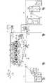
図2は実施例1の冷却機構の斜視図である。
図3は実施例1の媒体冷却部材の要部説明図であり、図3Aは端部の斜視図、図3Bは図3AのIIIB-IIIB線断面図である。
図2、図3において、実施例1の媒体冷却装置の一例としての冷却機構U3aでは、第1の冷却ロールR11は、回転中心の一例として、軸方向に延びるシャフト1を有する。シャフト1の両端部には、軸受け2を介して、案内体の支持部の一例としてのハブ部3が回転可能に支持されている。ハブ部3には、気体の案内体の一例としての内筒4が支持されている。内筒4は、シャフト1を囲む円筒状、スリーブ状に形成されている。(Explanation of medium cooling member)
FIG. 2 is a perspective view of the cooling mechanism of the first embodiment.
FIG. 3 is an explanatory view of a main part of the medium cooling member of the first embodiment, FIG. 3A is a perspective view of an end portion, and FIG. 3B is a sectional view taken along line IIIB-IIIB of FIG. 3A.
In FIGS. 2 and 3, in the cooling mechanism U3a as an example of the medium cooling device of the first embodiment, the first cooling roll R11 has a
図3Aにおいて、ハブ部3には、連結部の一例としてのスポーク部6の径方向内端が接続されている。実施例1のスポーク部6は、放射状に4つ配置されている。
スポーク部6の径方向外端には、本体の支持部の一例としてのリム部7が接続されている。実施例1のリム部7はシャフト1を中心とする円環状(リング状)に形成されている。
リム部7には、回転部の一例であって、冷却部材の本体の一例としての外筒8が支持されている。外筒8は、内筒4と同軸の円筒状、スリーブ状に形成されている。実施例1の第1の冷却ロールR11では、外筒8の外表面に連続紙Sが巻付くように接触し、連続紙Sの搬送に伴って外筒8が従動回転する。In FIG. 3A, the
A
The
図3において、シャフト1の両端部は、ハブ部3よりも軸方向の外側で、固定支持部の一例としての軸支持部11に支持されている。図3Aにおいて、軸支持部11は、下端が移動体の一例としてのスライダ12に支持されている。
図3Bにおいて、軸支持部11には、気体の案内体の一例としてのキャップ13が支持されている。キャップ13は、軸支持部11およびシャフト1の軸方向の外側を覆っている。
図2、図3Bにおいて、スライダ12には、気体の案内体の一例としての端部カバー14が支持されている、端部カバー14は、中空の円錐状に形成されており、軸方向の端部に行くにつれて内径が小さくなるように形成されている。In FIG. 3, both ends of the
In FIG. 3B, the
In FIGS. 2 and 3B, the
したがって、図3Bに示すように端部カバー14とキャップ13との間や、外筒8と内筒4との間に、通気部の一例として、気体が軸方向の一端から他端に向けて通過可能な流路16が形成されている。
端部カバー14の軸方向外側には、移送部材の一例としてのファン17が支持されている。実施例1の第1の冷却ロールR11では、軸方向の前側に第1の移送部材の一例としての前側ファン17aが支持され、軸方向の後ろ側に第2の移送部材の一例としての後側ファン17bが支持されている。なお、実施例1の前側ファン17aは、作動時に前方から後方に気体を移送するように設置されている。また、後側ファン17bは、作動時に後方から前方に気体を移送するように設置されている。Therefore, as shown in FIG. 3B, as an example of the ventilation portion between the
A
図2において、前記スライダ12は、冷却部材の案内体の一例としてのガイドレール21に移動可能に支持されている。ガイドレール21は、軸方向(前後方向)に交差する方向である左右方向に沿って延びており、スライダ12を左右方向に移動可能に支持する。スライダ12は、図示しないモータでガイドレール21に沿って移動可能に支持されている。したがって、利用者の入力、設定に応じて、第1の冷却ロールR11が左右方向に移動して、第1の冷却ロールR11に対する連続紙Sの巻付き角(巻付き量)や、連続紙Sの張力を変更、調整することが可能である。 In FIG. 2, the
図2において、第1の冷却ロールR11の左方には、第1の外部冷却器26が支持されている。第1の外部冷却器26は、第1の冷却ロールR11と対向して配置されている。第1の外部冷却器26は、第1の冷却ロールR11の軸方向に沿って、筐体の一例としてのハウジング27が延びている。ハウジング27の前端部には、吸気口27aが形成されている。ハウジング27には、移送部材の一例としてのファン28が複数配置されている。ファン28は、第1の冷却ロールR11の軸方向に複数配置されている。したがって、ファン28からの気体は、外筒8の外表面に吹き付けられる。 In FIG. 2, a first
図2において、実施例1の第2の冷却ロールR12も、第1の冷却ロールR11と同様に構成されている。すなわち、内筒4′(図示せず)と外筒8′の二重筒構造を有し、前後両端にファン17a′,17b′(前側のみ図示)が配置されている。なお、実施例1では、第2の冷却ロールR12のファン17a′,17b′は、第1の冷却ロール17a,17bと、ファン径等の仕様が同一のファンが使用され、部品が共通化されている。また、第2の冷却ロールR12も、スライダ12′がガイドレール21′に沿って左右方向にスライド移動可能に支持される。 In FIG. 2, the second cooling roll R12 of the first embodiment is configured in the same manner as the first cooling roll R11. That is, it has a double cylinder structure of an inner cylinder 4'(not shown) and an outer cylinder 8', and fans 17a'and 17b' (only the front side is shown) are arranged at both front and rear ends. In the first embodiment, the fans 17a'and 17b' of the second cooling roll R12 use fans having the same specifications such as the fan diameter as the first cooling rolls 17a and 17b, and the parts are standardized. ing. Further, the second cooling roll R12 is also supported so that the slider 12'can slide and move in the left-right direction along the guide rail 21'.
なお、実施例1の第2の冷却ロールR12は、第1の冷却ロールR11に比べて、内筒4′および外筒8′が小径に形成されている。したがって、第2の冷却ロールR12は、第1の冷却ロールR11に比べて、連続紙Sの冷却能力、すなわち、連続紙Sから吸熱する熱量、言い換えれば、連続紙Sから放熱される熱量が低く設定されている。 In the second cooling roll R12 of the first embodiment, the inner cylinder 4'and the outer cylinder 8'are formed to have smaller diameters than the first cooling roll R11. Therefore, the second cooling roll R12 has a lower cooling capacity of the continuous paper S, that is, the amount of heat absorbed from the continuous paper S, that is, the amount of heat dissipated from the continuous paper S, as compared with the first cooling roll R11. It is set.
また、実施例1の第2の冷却ロールR12では、第1の冷却ロールR11の外筒8と異なり、外筒8′の外表面には、連続紙Sの画像が転写、定着された面に接触するため、現像剤が付着しにくい離型層が形成されている。離型層は、必要とされる離型性に応じて任意の構成を採用可能であるが、フッ素樹脂を被膜することも可能であるし、表層を粗面加工して離型層とすることも可能である。 Further, in the second cooling roll R12 of the first embodiment, unlike the
また、第2の冷却ロールR12に対応して、第2の外部冷却器26′が配置されている。また、実施例1の第2の外部冷却器26′は、第1の外部冷却器26と同一仕様のファン28′を有する。実施例1の第2の外部冷却器26′は、第2の冷却ロールR12に対して、連続紙Sを挟んで対向している。したがって、第2の外部冷却器26′は、第1の外部冷却器26と異なり、連続紙Sに風を吹き付けて冷却している。したがって、連続紙Sに汚れが付着しないように、第2の外部冷却器26′のファン28′の吹出口には、フィルターを設けることが好ましい。 Further, a second external cooler 26'is arranged corresponding to the second cooling roll R12. Further, the second external cooler 26'of Example 1 has a fan 28'with the same specifications as the first
(実施例1の制御部の説明)
図2において、実施例1の各ファン17,17′,28,28′は、制御手段の一例としてのプリンタUの制御部Cにより制御される。制御部Cは、外部との信号の入出力等を行う入出力インターフェースI/Oを有する。また、制御部Cは、必要な処理を行うためのプログラムおよび情報等が記憶されたROM:リードオンリーメモリを有する。また、制御部Cは、必要なデータを一時的に記憶するためのRAM:ランダムアクセスメモリを有する。また、制御部Cは、ROM等に記憶されたプログラムに応じた処理を行うCPU:中央演算処理装置を有する。したがって、実施例1の制御部Cは、小型の情報処理装置、いわゆるマイクロコンピュータにより構成されている。よって、制御部Cは、ROM等に記憶されたプログラムを実行することにより種々の機能を実現することができる。(Explanation of Control Unit of Example 1)
In FIG. 2, each
(制御部Cの機能)
制御部Cは、第1の冷却部材の制御手段の一例としての第1の冷却ロールの制御手段C1を有する。第1の冷却ロールの制御手段C1は、前側ファンの制御手段C1Aと、後側ファンの制御手段C1Bとを有する。
前側ファンの制御手段C1Aは、前側ファン17aの作動と停止を制御する。実施例1の前側ファンの制御手段C1Aは、画像形成動作時に、予め設定された間隔で前側ファン17aを作動または停止させる。実施例1では、前側ファンの制御手段C1Aは、予め設定された間隔の一例としての1分間隔で、前側ファン17aの作動と停止を繰り返す。(Function of control unit C)
The control unit C has a control means C1 for the first cooling roll as an example of the control means for the first cooling member. The control means C1 of the first cooling roll has a control means C1A for the front fan and a control means C1B for the rear fan.
The front fan control means C1A controls the operation and stop of the
後側ファンの制御手段C1Bは、後側ファン17bの作動と停止を制御する。実施例1の後側ファンの制御手段C1Bは、前側ファン17aの作動と停止に連動して、後側ファン17bを停止または作動させる。
したがって、実施例1では、前側ファン17aと後側ファン17bの一方が作動し、且つ、他方が停止するように制御される。よって、前側ファン17aが作動中(後側ファン17bは停止中)は、第1の冷却ロールR11の流路16には、前から後ろに向けて気体が流れ、後側ファン17bが作動中(前側ファン17aは停止中)は、流路16には後ろから前に向けて気体が流れる。The rear fan control means C1B controls the operation and stop of the
Therefore, in the first embodiment, one of the
制御部Cの第2の冷却ロールの制御手段C2は、第1の冷却ロールの制御手段C1と同様に、前側ファンの制御手段C2Aと後側ファンの制御手段C2bと有する。前側ファンの制御手段C2Aおよび後側ファンの制御手段C2Bは、前述した第1の冷却ロールの制御手段C1の前側ファンの制御手段C1Aおよび後側ファンの制御手段C1Bと同様に、前側ファン17a′および後側ファン17b′を予め設定された間隔で交互に作動および停止させる。
制御部Cの外部冷却器の制御手段C3は、画像形成動作中に、外部冷却器26,26′を作動させる。The control means C2 of the second cooling roll of the control unit C has the control means C2A of the front fan and the control means C2b of the rear fan, similarly to the control means C1 of the first cooling roll. The front fan control means C2A and the rear fan control means C2B are the same as the front fan control means C1A and the rear fan control means C1B of the first cooling roll control means C1 described above. And the rear fan 17b'is alternately activated and stopped at preset intervals.
The control means C3 of the external cooler of the control unit C operates the
(実施例1の作用)
前記構成を備えた実施例1のプリンタUでは、画像形成動作の一例としてのジョブが開始されると、連続紙Sに画像が転写され、定着される。定着時に定着装置Fで加熱された連続紙Sの部分が冷却ロールR11,R12に差し掛かると、連続紙Sが冷却ロールR11,R12に接触して冷却される。(Action of Example 1)
In the printer U of the first embodiment having the above configuration, when a job as an example of the image forming operation is started, the image is transferred to the continuous paper S and fixed. When the portion of the continuous paper S heated by the fixing device F at the time of fixing approaches the cooling rolls R11 and R12, the continuous paper S comes into contact with the cooling rolls R11 and R12 and is cooled.
特許文献1に記載の構成のように、用紙に接触する冷却ロールを冷却するファン等を有しない構成では、複数ページの印刷が行われると経時的に冷却ロールの温度が上昇して冷却能力が低下していく。特に、連続紙を使用する構成では、紙に接触し続けているので、冷却ロールの温度が上昇しやすい。冷却能力が低下して用紙の冷却が不十分になると、冷却ロールの下流側の搬送ロールR13~R15に接触する際に、搬送ロールR13~R15に画像の一部が付着(画像抜け)したり、光沢にムラが発生する等の画像欠陥が発生しやすくなる。また、冷却が不十分な用紙が巻き取られた場合(連続紙)や排出トレイに排出された場合(カット紙)では、冷却が不十分な画像が次に重ねられた用紙に貼り付く問題がある。 In a configuration without a fan or the like for cooling the cooling roll in contact with the paper as in the configuration described in
また、特許文献2に記載の構成のように、ガイド板に通風孔を形成する構成では、用紙が部材に接触せずに冷却されると、接触して熱伝導で冷却する場合に比べて冷却効率が低い問題がある。また、用紙の前端が風に押されてガイド板に押し付けられる形になると、ガイド板に用紙の角が引っかかって紙詰まりが発生しやすくなる問題もある。
さらに、特許文献3に記載の構成のように、液体を使用すると、液体の漏れ出し等の対策も必要となる。したがって、漏れ出した液体が用紙をぬらさないように対策も必要となり、費用が高くなる問題がある。Further, in the configuration in which the ventilation holes are formed in the guide plate as in the configuration described in
Further, when a liquid is used as in the configuration described in
図4は比較例の実験結果の説明図であり、横軸に時間を取り、縦軸に温度を取ったグラフである。
図4において、富士ゼロックス社製のColor 1000 Pressを改造して、実験を行った。実験では、連続紙の搬送速度を500mm/sに設定し、第1の冷却ロールのロール径をφ200mm、前側ファン17aのみで冷却を行った。そして、冷却ロールの前側と後側に温度センサを配置して温度を計測した。
図4において、実験の結果、1分が経過するまでは、冷却ロールの前側と後側で温度差はほとんど発生しなかったが、1分を経過した後は、前側と後側とで温度差が発生し、時間が経過するほど温度差が拡大していった。FIG. 4 is an explanatory diagram of the experimental results of the comparative example, and is a graph in which time is taken on the horizontal axis and temperature is taken on the vertical axis.
In FIG. 4, the Color 1000 Press manufactured by Fuji Xerox Co., Ltd. was modified and an experiment was conducted. In the experiment, the transport speed of continuous paper was set to 500 mm / s, the roll diameter of the first cooling roll was φ200 mm, and cooling was performed only with the
In FIG. 4, as a result of the experiment, there was almost no temperature difference between the front side and the rear side of the cooling roll until 1 minute passed, but after 1 minute, the temperature difference between the front side and the rear side. Occurred, and the temperature difference increased as time passed.
したがって、図4に示す結果から、冷却ロールの軸方向の一方からファンで冷却する構成では、冷却ロールの軸方向の一方側と他方側とで冷却能力に経時的に差が発生する。したがって、用紙の幅方向の一方側と他方側とで冷却ムラ、温度ムラが発生することとなる。したがって、光沢ムラの発生や用紙の貼り付きの問題が発生する恐れがある。
これらに対して、実施例1のプリンタUでは、冷却ロールR11,R12のファン17,17′が前側と後側から交互に気流を発生させて、外筒8,8′を冷却している。したがって、冷却ロールR11,R12からの放熱を促す気流を特定の一方向(前側のみまたは後側のみ)から吹き付ける場合に比べて、連続紙Sの幅方向における連続紙Sの冷却ムラを抑制することが可能である。したがって、形成された画像の画質欠陥の発生や、連続紙Sの貼り付きの発生も低減される。また、実施例1の冷却ロールR11,R12を使用した場合、前述の特許文献2,3に記載の問題も発生しない。Therefore, from the results shown in FIG. 4, in the configuration in which cooling is performed by a fan from one of the axial directions of the cooling roll, a difference in cooling capacity occurs over time between one side and the other side of the cooling roll in the axial direction. Therefore, uneven cooling and uneven temperature occur on one side and the other side in the width direction of the paper. Therefore, there is a possibility that uneven gloss may occur and problems such as paper sticking may occur.
On the other hand, in the printer U of the first embodiment, the
さらに、実施例1のプリンタUでは、連続紙Sに接触する外筒8の内側に内筒4が配置されている。したがって、気流は、外筒8側に導かれる。特に、実施例1では、ハブ部3やキャップ13で内筒4の内側に気体が流入することが抑制されており、ほとんどの気体が外筒8側にガイドされる。仮に、内筒4を有しない構成では、シャフト1の近傍にも流れ、冷却する必要のある外筒8の近傍の風量が減少する。よって、内筒4を有する実施例1の冷却ロールR11,R12では、内筒4を有しない構成に比べて、冷却性能が向上する。 Further, in the printer U of the first embodiment, the
また、実施例1のプリンタUでは、第1の冷却ロールR11は、第1の外部冷却器26で外部からも冷却されている。したがって、第1の外部冷却器26を有しない構成に比べて、冷却性能が向上している。また、特許文献1に記載の構成のように、一般に、冷却ロールは、用紙に接触した領域で吸熱し、用紙が接触していない領域で放熱することとなる。カット紙を使用する場合は、先行用紙と後続用紙との間で用紙に接触しない期間もあり、放熱の機会が多い。しかし、連続紙は用紙に接触し続けるとともに、連続紙Sの巻付き角が大きくなると用紙に接触しない面積が狭くなって放熱しにくくなり、冷却性能が低下しやすい。したがって、第1の外部冷却器26が設けられていない構成では、冷却性能が特に低下しやすくなるが、実施例1では、第1の外部冷却器26で、冷却性能が維持されやすくなっている。 Further, in the printer U of the first embodiment, the first cooling roll R11 is also cooled from the outside by the first
さらに、実施例1では、2つの冷却ロールR11,R12を使用しており、冷却ロールが1つの場合に比べて冷却効率が向上している。
また、実施例1の冷却ロールR11,R12では、上流側の第1の冷却ロールR11は、連続紙Sの画像が転写、定着された面(画像面)とは逆側の面に接触し、下流側の第2の冷却ロールR12は、画像面に接触する。上流側の冷却ロールが画像面に接触する構成では、十分に冷却されていない状態で接触することとなり、画像抜け等の画質低下が発生する可能性が高くなるが、実施例1では、上流側の第1の冷却ロールR11が非画像面に接触しており画質低下の発生が抑制されている。Further, in the first embodiment, two cooling rolls R11 and R12 are used, and the cooling efficiency is improved as compared with the case where the cooling roll is one.
Further, in the cooling rolls R11 and R12 of the first embodiment, the first cooling roll R11 on the upstream side comes into contact with the surface opposite to the surface (image surface) on which the image of the continuous paper S is transferred and fixed. The second cooling roll R12 on the downstream side comes into contact with the image plane. In the configuration in which the cooling roll on the upstream side comes into contact with the image surface, the cooling roll on the upstream side comes into contact in a state where the image surface is not sufficiently cooled, and there is a high possibility that image quality deterioration such as image omission occurs. The first cooling roll R11 is in contact with the non-image surface, and the occurrence of image quality deterioration is suppressed.
特に、実施例1の冷却ロールR11,R12では、上流側の第1の冷却ロールR11の方が、外径が大きく、冷却能力が高い。一般に温度差が大きいほど熱伝導が大きくなって、冷却効率が高いことが知られている。連続紙Sは定着装置Fに近い上流側ほど高温であり、上流側の第1の冷却ロールR11の冷却能力が高い方が、全体としての冷却効率も高くなる。したがって、冷却ロールR11,R12の冷却性能が同一または下流側の方が、冷却能力が高い場合に比べて、全体として冷却効率が向上している。 In particular, in the cooling rolls R11 and R12 of the first embodiment, the first cooling roll R11 on the upstream side has a larger outer diameter and a higher cooling capacity. It is generally known that the larger the temperature difference, the larger the heat conduction and the higher the cooling efficiency. The temperature of the continuous paper S is higher toward the upstream side closer to the fixing device F, and the higher the cooling capacity of the first cooling roll R11 on the upstream side, the higher the cooling efficiency as a whole. Therefore, when the cooling performances of the cooling rolls R11 and R12 are the same or on the downstream side, the cooling efficiency is improved as a whole as compared with the case where the cooling capacity is high.
また、実施例1の冷却ロールR11,R12では、上流側の第1の冷却ロールR11で冷却された状態で、下流側の第2の冷却ロールR12で、画像面も冷却している。したがって、画像面側を冷却しない場合に比べて、画像面の現像剤も十分に冷却されやすい。したがって、下流側の搬送ロールR13~R15に接触した際に、画像抜けが発生したり、巻取りロールU3cで巻き取られた状態で、現像剤が重なった連続紙Sに貼り付きにくくなっている。
さらに、実施例1の冷却ロールR11,R12は、スライダ12がガイドレール21に沿って移動可能に支持されている。したがって、冷却ロールR11,R12をガイドレール21に沿って移動させると、連続紙Sの冷却ロールR11,R12への巻付き角が変化する。冷却ロールR11,R12が連続紙Sと接触する面積が広い方が、吸熱しやすくなって冷却能力が向上する。したがって、実施例1では、巻付き角を調整して、冷却ロールR11,R12の冷却能力を調整することが可能になっている。Further, in the cooling rolls R11 and R12 of the first embodiment, the image surface is also cooled by the second cooling roll R12 on the downstream side while being cooled by the first cooling roll R11 on the upstream side. Therefore, the developer on the image surface is likely to be sufficiently cooled as compared with the case where the image surface side is not cooled. Therefore, when the transport rolls R13 to R15 on the downstream side come into contact with each other, image omission occurs, and it is difficult for the developer to stick to the continuous paper S on which the developer is overlapped in a state of being wound by the take-up roll U3c. ..
Further, in the cooling rolls R11 and R12 of the first embodiment, the
(実施例1の変更例1)
図5は実施例1の変更例1の説明図である。
前記実施例1では、前側ファン17aと後側ファン17bは、それぞれ、軸方向の外側から内側に向けて気体を移送するように設置された構成を例示したがこれに限定されない。図5において、例えば、前側ファン17aおよび後側ファン17bを軸方向で逆に設置して、軸方向の内側から外側に気体を移送する構成とすることが可能である。いわば、実施例1では、各ファン17a,17bは、第1の冷却ロールR11の内部に「吸気」を行う構成であるが、第1の冷却ロールR11の内部から「排気」する構成とすることも可能である。すなわち、第1の排気部材の一例としての前側ファン51と、第2の排気部材の一例としての後側ファン52を設ける構成とすることも可能である。(
FIG. 5 is an explanatory diagram of a modified example 1 of the first embodiment.
In the first embodiment, the
(実施例1の変更例2)
図6は実施例1の変更例2の説明図である。
前記実施例1では、前側ファン17aおよび後側ファン17bが作動時に、特定の回転方向に回転して、特定の方向に気体を移送するファンで構成したが、これに限定されない。図6において、例えば、移送部材の一例としての正逆回転可能なファン61を使用して、予め設定された間隔(1分間隔)で正回転と逆回転を切り替えることで、気流の方向を切り替える構成とすることも可能である。なお、ファン自体の価格の面では、実施例1や実施例1の変更例1の方が低価格であり、有利である。(
FIG. 6 is an explanatory diagram of a modified example 2 of the first embodiment.
In the first embodiment, the
また、実施例1の変更例2において、軸方向の一方のファン61を正回転させて吸気するとともに、他方のファン62を逆回転させて排気することで、実施例1や実施例1の変更例1のように軸方向の一方だけで吸気または排気を行う構成に比べて、気流を強くすることが可能である。したがって、冷却ロールR11,R12の冷却効率を向上させることが可能である。
なお、正逆回転可能なファン61,62とした場合は、軸方向の両側に配置することが望ましいが、軸方向の一方のみに設ける構成とすることも可能であるし、両側に設ける構成とすることも可能である。
さらに、ファン61,62の位置は、軸方向の端部に限定されず、図6の破線で示すように、内筒4の一部または全部を取り外して、軸方向で内部に1つ配置する構成とすることも可能である。内部に配置する場合、冷却ロールR11,R12の端部にファン61,62を配置する場合に比べて、冷却ロールR11,R12の全体の軸方向の長さを小型化することが可能である。Further, in the second modification of the first embodiment, one
When the
Further, the positions of the
(実施例1の変更例3)
図7は実施例1の変更例3の説明図である。
前記実施例1では、前側ファン17aおよび後側ファン17bにそれぞれ1つずつ吸気用のファンを配置したが、これに限定されない。図7において、例えば、冷却ロールR11,R12の軸方向の前側に、第1の吸気部材の一例としての吸気用のファン17aと第1の排気部材の一例としての排気用ファン71を配置し、後側に第2の吸気部材の一例としての吸気用のファン17bと第2の排気部材の一例としての排気用ファン72を配置し、軸方向の一方で吸気用のファンが作動している状態では、他方で排気用のファンを作動させて気流を発生させる構成とすることも可能である。
なお、吸気用のファン17a,17bと排気用のファン71,72は、図7に示すように、径方向に隣り合うように配置することも可能であるし、軸方向に隣り合うように配置することも可能である。(
FIG. 7 is an explanatory diagram of a modified example 3 of the first embodiment.
In the first embodiment, one fan for intake is arranged for each of the
As shown in FIG. 7, the
(実施例1の変更例4)
図8は実施例1の変更例4の説明図である。
前記実施例1では、気流の向きを切り替える時期を、1分間隔とする構成を例示したが、これに限定されない。図8において、例えば、冷却ロールR11,R12の軸方向の両端部に、温度検知部材の一例としての温度センサSN1,SN2を設置して、外筒8の外表面の温度を検知し、2つの温度センサSN1,SN2の検知する温度が、所定の温度上限値以上になった場合に、気流の向きを切り替えるようにすることも可能である。また、温度差が、所定の温度差以上になった場合に切り替える構成とすることも可能である。(
FIG. 8 is an explanatory diagram of a modified example 4 of the first embodiment.
In the first embodiment, the configuration in which the time for switching the direction of the airflow is set to one minute intervals has been exemplified, but the present invention is not limited to this. In FIG. 8, for example, temperature sensors SN1 and SN2 as an example of the temperature detecting member are installed at both ends of the cooling rolls R11 and R12 in the axial direction to detect the temperature of the outer surface of the
(変更例)
以上、本発明の実施例を詳述したが、本発明は、前記実施例に限定されるものではなく、特許請求の範囲に記載された本発明の要旨の範囲内で、種々の変更を行うことが可能である。本発明の変更例(H01)~(H011)を下記に例示する。
(H01)前記実施例において、画像形成装置の一例としてのプリンタUを例示したが、これに限定されず、例えば、複写機、FAX、あるいはこれらの複数または全ての機能を有する複合機等により構成することも可能である。(Change example)
Although the embodiments of the present invention have been described in detail above, the present invention is not limited to the above embodiments, and various modifications are made within the scope of the gist of the present invention described in the claims. It is possible. Examples of modifications (H01) to (H011) of the present invention are illustrated below.
(H01) In the above embodiment, the printer U as an example of the image forming apparatus has been exemplified, but the present invention is not limited to this, and the printer U is composed of, for example, a copying machine, a fax machine, or a multifunction device having a plurality or all of these functions. It is also possible to do.
(H02)前記実施例において、プリンタUとして、5色の現像剤が使用される構成を例示したが、これに限定されず、例えば、単色の画像形成装置や、4色以下または6色以上の多色の画像形成装置にも適用可能である。
(H03)前記実施例において、転写部材の一例として、冷却ロールR11,R12は、2つ設ける構成を例示したが、これに限定されない。必要な冷却性能に応じて、1つとしたり、3つ以上とすることも可能である(H02) In the above embodiment, a configuration in which a five-color developer is used as the printer U has been exemplified, but the present invention is not limited to this, and for example, a monochromatic image forming apparatus, four colors or less, or six or more colors or more. It can also be applied to a multicolor image forming apparatus.
(H03) In the above embodiment, as an example of the transfer member, two cooling rolls R11 and R12 are provided, but the present invention is not limited to this. Depending on the required cooling performance, it can be one or three or more.
(H04)前記実施例において、ファン17,17′は軸方向の端部に配置する構成を例示したが、軸方向の中央部に配置することも可能である。
(H05)前記実施例において、内筒4を有する構成とすることが望ましいが、内筒4を有しない構成とすることも可能である。
(H06)前記実施例において、外部冷却器26,26′を設けることが望ましいが、設けない構成とすることも可能である。(H04) In the above embodiment, the
(H05) In the above embodiment, it is desirable to have a configuration having an
(H06) In the above embodiment, it is desirable to provide the
(H07)前記実施例において、スライダ12とガイドレール21のように、巻付き角を調整可能な構成を有することが望ましいが、これに限定されない。巻付き角を調整するための構成を設けないことも可能である。また、スライダ12とガイドレール21ではなく、上流側または下流側に連続紙Sを押して連続紙の姿勢、経路を、冷却ロールに対して変化させて巻付き角を調整する構成とすることも可能である。(H07) In the above embodiment, it is desirable to have a configuration in which the winding angle can be adjusted, such as the
(H08)前記実施例において、外筒8は連続紙Sに従動回転する構成を例示したが、これに限定されない。外筒8がモータとギアで駆動される構成とすることも可能である。
(H09)前記実施例において、前側ファン17aと後側ファン17bとは、交互に作動と停止をさせる構成を例示したが、これに限定されない。ファン17a,17bの回転が安定するまでの時間や、既に送り出した気流が反対側の端に到達するまでの時間等を考慮して、ファン17a,17bの切り替え時に、両方が停止している期間があったり、逆に、両方が作動している期間を設けたりすることも可能である。(H08) In the above embodiment, the
(H09) In the above embodiment, the
(H010)前記実施例において、本発明は連続紙Sを使用する画像形成装置において公的に使用可能であるが、カット紙を使用する画像形成装置にも適用可能である。
(H011)前記実施例において、各冷却ロールR11,R12は、連続紙Sに従動回転する構成を例示したが、これに限定されない。冷却ロールR11,R12の一方または両方の外筒8,8′がモータ等の駆動源からの駆動を受けて駆動する構成とすることも可能である。(H010) In the above embodiment, the present invention can be publicly used in an image forming apparatus using continuous paper S, but can also be applied to an image forming apparatus using cut paper.
(H011) In the above embodiment, each of the cooling rolls R11 and R12 exemplifies a configuration in which the continuous paper S is driven to rotate, but the present invention is not limited thereto. It is also possible to configure the
8,8′…回転部、
16…通気部、
17,17′…移送部材、
17a…第1の吸気部材、
17a,51,61,71…第1の移送部材、
17b…第2の吸気部材、
17b,52,62,72…第2の移送部材、
71…第1の排気部材、
72…第2の排気部材、
C…制御部、
F…定着装置、
Py,Pm,Pc,Pk,Po…像保持体、
R11,R12…媒体冷却部材、
S…媒体、
SN1,SN2…検知部材、
T1,B,T2…転写装置、
U…画像形成装置。8,8'... Rotating part,
16 ... Ventilation part,
17, 17'... Transfer member,
17a ... First intake member,
17a, 51, 61, 71 ... First transfer member,
17b ... Second intake member,
17b, 52, 62, 72 ... Second transfer member,
71 ... First exhaust member,
72 ... Second exhaust member,
C ... Control unit,
F ... Fixing device,
Py, Pm, Pc, Pk, Po ... Image holder,
R11, R12 ... Medium cooling member,
S ... medium,
SN1, SN2 ... Detection member,
T1, B, T2 ... Transfer device,
U ... Image forming apparatus.
Claims (9)
Translated fromJapanese前記回転部の内面に沿い且つ前記回転部の回転軸方向に沿って延び、気体が通過可能な通気部と、
前記回転部の回転中心の軸方向の両端部の外側を覆い、軸方向の外側からの気体を軸方向の中心部から径方向外側の通気部に向けて案内する第1の気体の案内体と、
前記通気部の軸方向の両端部に配置され且つ前記第1の気体の案内体に対して径方向で内側に間隔をあけて配置され、前記回転中心の軸方向の端部にいくにつれて窄まる形状に形成され、軸方向の外側からの気体を径方向の中心部から径方向外側の通気部に向けて案内する第2の気体の案内体と、
前記通気部に空気を移送する移送部材と、
前記通気部に対して軸方向の一方からの空気の移送と前記軸方向の他方からの空気の移送とを切り替える制御部と、
を備えたことを特徴とする媒体冷却部材。A rotating part that rotates when the outer surface comes into contact with the medium,
A ventilation section that extends along the inner surface of the rotating section and along the rotation axis direction of the rotating section and allows gas to pass through.
With a first gas guide body that covers the outside ofboth ends in the axial direction of the rotation center of the rotating portion and guides gas from the outside in the axial direction from the central portion in the axial direction toward the venting portion on the outer side in the radial direction. ,
It is arranged atboth ends of the ventilation portion in the axial directionand is arranged at intervals inward in the radial direction with respect to the guide body of the first gas, and narrows toward the axial end portion of the center of rotation. A second gas guide, which is formed in a shape and guides the gas from the outside in the axial direction from the center in theradial direction toward the ventilation part on the outer side in the radial direction.
A transfer member that transfers air to the vent and
A control unit that switches between the transfer of air from one axial direction and the transfer of air from the other axial direction to the ventilation unit.
A medium cooling member characterized by being provided with.
を備えたことを特徴とする請求項1に記載の媒体冷却部材。The transfer member having a first transfer member arranged at one end in the axial direction and a second transfer member arranged at the other end in the axial direction.
The medium cooling member according to claim 1, wherein the medium cooling member is provided.
軸方向の他方の端部に配置され且つ軸方向の他方から一方に向けて気体を移送する第2の移送部材と、
前記第1の移送部材と前記第2の移送部材の一方とを交互に作動させ、且つ、他方を交互に作動停止させる前記制御部と、
を備えたことを特徴とする請求項2に記載の媒体冷却部材。A first transfer member located at one end in the axial direction and transferring gas from one axial direction to the other.
A second transfer member located at the other end in the axial direction and transferring gas from the other in the axial direction toward one.
The control unit that alternately operates one of the first transfer member and the second transfer member and alternately stops the operation of the other.
The medium cooling member according to claim 2, wherein the medium cooling member is provided.
前記第1の吸気部材および前記第2の排気部材とを作動させ且つ前記第2の吸気部材および前記第1の排気部材とを停止させる状態と、前記第2の吸気部材および前記第1の排気部材とを作動させ且つ前記第1の吸気部材および前記第2の排気部材とを停止させる状態と、を切り替える制御部と、
を備えたことを特徴とする請求項2または3に記載の媒体冷却部材。A first intake member arranged at one end in the axial direction and transferring gas from one of the axial directions of the rotating portion toward the other, and a first intake member arranged at one end in the axial direction and of the rotating portion. The first transfer member having a first exhaust member that transfers gas from the other in the axial direction toward one, and the first transfer member that is arranged at the other end in the axial direction and from the other in the axial direction of the rotating portion. A second intake member that transfers gas toward one side, and a second exhaust member that is arranged at the other end in the axial direction and transfers gas from one axial direction of the rotating portion toward the other. With the second transfer member having
A state in which the first intake member and the second exhaust member are operated and the second intake member and the first exhaust member are stopped, and the second intake member and the first exhaust member. A control unit that switches between a state in which the member is operated and the first intake member and the second exhaust member are stopped.
The medium cooling member according to claim 2 or 3, wherein the medium cooling member is provided with.
前記移送部材の正回転と逆回転とを切り替える前記制御部と、
を備えたことを特徴とする請求項1ないし4のいずれかに記載の媒体冷却部材。The transfer member that rotates to transfer gas, and is capable of forward and reverse rotation, and the transfer member.
The control unit that switches between forward rotation and reverse rotation of the transfer member,
The medium cooling member according to any one of claims 1 to 4, wherein the medium cooling member is provided.
を備えたことを特徴とする請求項5に記載の媒体冷却部材。A transfer member located at the axial end of the rotating part,
The medium cooling member according to claim 5, wherein the medium cooling member is provided.
を備えたことを特徴とする請求項1ないし6のいずれかに記載の媒体冷却部材。A control unit that switches when a preset period has elapsed,
The medium cooling member according to any one of claims 1 to6 , wherein the medium cooling member is provided.
検知部材で検知された温度が、予め設定された温度に達した場合に、前記空気の移送方向を切り替える制御部と、
を備えたことを特徴とする請求項1ないし7のいずれかに記載の媒体冷却部材。A detection member that detects the temperature of the rotating part, and
A control unit that switches the air transfer direction when the temperature detected by the detection member reaches a preset temperature.
The medium cooling member according to any one of claims 1 to7 , wherein the medium cooling member is provided.
前記像保持体の表面の画像を媒体に転写する転写装置と、
媒体に転写された画像を加熱して定着する定着装置と、
前記定着装置に対して媒体搬送方向の下流側に配置され、画像定着後の媒体を冷却する請求項1ないし8のいずれかに記載の媒体冷却部材と、
を備えたことを特徴とする画像形成装置。Image holder and
A transfer device that transfers an image of the surface of the image holder to a medium,
A fixing device that heats and fixes the image transferred to the medium,
The medium cooling member according to any one of claims 1 to8 , which is arranged on the downstream side in the medium transport direction with respect to the fixing device and cools the medium after image fixing.
An image forming apparatus characterized by being equipped with.
Priority Applications (3)
| Application Number | Priority Date | Filing Date | Title |
|---|---|---|---|
| JP2017181516AJP7047300B2 (en) | 2017-09-21 | 2017-09-21 | Medium cooling member and image forming device |
| US16/004,438US10353342B2 (en) | 2017-09-21 | 2018-06-11 | Medium cooling apparatus and medium cooling member |
| CN201810863762.2ACN109541920B (en) | 2017-09-21 | 2018-08-01 | Medium cooling apparatus and image forming apparatus |
Applications Claiming Priority (1)
| Application Number | Priority Date | Filing Date | Title |
|---|---|---|---|
| JP2017181516AJP7047300B2 (en) | 2017-09-21 | 2017-09-21 | Medium cooling member and image forming device |
Publications (2)
| Publication Number | Publication Date |
|---|---|
| JP2019056835A JP2019056835A (en) | 2019-04-11 |
| JP7047300B2true JP7047300B2 (en) | 2022-04-05 |
Family
ID=66106550
Family Applications (1)
| Application Number | Title | Priority Date | Filing Date |
|---|---|---|---|
| JP2017181516AActiveJP7047300B2 (en) | 2017-09-21 | 2017-09-21 | Medium cooling member and image forming device |
Country Status (1)
| Country | Link |
|---|---|
| JP (1) | JP7047300B2 (en) |
Citations (6)
| Publication number | Priority date | Publication date | Assignee | Title |
|---|---|---|---|---|
| JP2000056598A (en) | 1998-06-05 | 2000-02-25 | Ricoh Co Ltd | Fixing device |
| JP2002072764A (en) | 2000-09-04 | 2002-03-12 | Ricoh Co Ltd | Image forming device |
| US20030063937A1 (en) | 2001-09-28 | 2003-04-03 | Toshiba Tec Kabushiki Kaisha | Image forming apparatus |
| JP2005321622A (en) | 2004-05-10 | 2005-11-17 | Konica Minolta Business Technologies Inc | Fixing apparatus |
| JP2007065090A (en) | 2005-08-29 | 2007-03-15 | Sharp Corp | Image forming apparatus |
| JP2008281879A (en) | 2007-05-11 | 2008-11-20 | Ricoh Co Ltd | Fixing apparatus and image forming apparatus |
Family Cites Families (1)
| Publication number | Priority date | Publication date | Assignee | Title |
|---|---|---|---|---|
| JPH03139670A (en)* | 1989-10-26 | 1991-06-13 | Ricoh Co Ltd | Image forming device ventilation device |
- 2017
- 2017-09-21JPJP2017181516Apatent/JP7047300B2/enactiveActive
Patent Citations (6)
| Publication number | Priority date | Publication date | Assignee | Title |
|---|---|---|---|---|
| JP2000056598A (en) | 1998-06-05 | 2000-02-25 | Ricoh Co Ltd | Fixing device |
| JP2002072764A (en) | 2000-09-04 | 2002-03-12 | Ricoh Co Ltd | Image forming device |
| US20030063937A1 (en) | 2001-09-28 | 2003-04-03 | Toshiba Tec Kabushiki Kaisha | Image forming apparatus |
| JP2005321622A (en) | 2004-05-10 | 2005-11-17 | Konica Minolta Business Technologies Inc | Fixing apparatus |
| JP2007065090A (en) | 2005-08-29 | 2007-03-15 | Sharp Corp | Image forming apparatus |
| JP2008281879A (en) | 2007-05-11 | 2008-11-20 | Ricoh Co Ltd | Fixing apparatus and image forming apparatus |
Also Published As
| Publication number | Publication date |
|---|---|
| JP2019056835A (en) | 2019-04-11 |
Similar Documents
| Publication | Publication Date | Title |
|---|---|---|
| JP5737531B2 (en) | Fixing apparatus and image forming apparatus | |
| JP4586867B2 (en) | Fixing apparatus and image forming apparatus | |
| JP7000041B2 (en) | Image forming device | |
| JP2004271563A (en) | Fixing device | |
| JP7047300B2 (en) | Medium cooling member and image forming device | |
| JP7336260B2 (en) | image forming device | |
| JP6052328B2 (en) | Fixing apparatus and image forming apparatus | |
| US9658587B2 (en) | Fixing device and image forming apparatus | |
| JP5034831B2 (en) | Fixing apparatus and image forming apparatus | |
| JP7009873B2 (en) | Medium cooling device and image forming device | |
| JP7009917B2 (en) | Medium cooling device and image forming device | |
| US11221586B2 (en) | Image forming apparatus | |
| CN109541920B (en) | Medium cooling apparatus and image forming apparatus | |
| JP6826774B2 (en) | Fixing device and image forming device | |
| JP6128368B2 (en) | Fixing apparatus and image forming apparatus | |
| JP7651972B2 (en) | Blower device and image forming apparatus | |
| JP2003029485A (en) | Color image fixing device | |
| JP4315039B2 (en) | Fixing device | |
| JP2019060949A (en) | Fixing device and image forming apparatus | |
| CN108073061B (en) | image forming apparatus | |
| JP2023031857A (en) | Exhaust device and image formation apparatus | |
| JP6103262B2 (en) | Fixing apparatus and image forming apparatus | |
| JP2023138666A (en) | Cooling system | |
| JP2024048147A (en) | Media scratch repair device and image forming device | |
| JP6794642B2 (en) | Cooling device and image forming device |
Legal Events
| Date | Code | Title | Description |
|---|---|---|---|
| A621 | Written request for application examination | Free format text:JAPANESE INTERMEDIATE CODE: A621 Effective date:20200831 | |
| A977 | Report on retrieval | Free format text:JAPANESE INTERMEDIATE CODE: A971007 Effective date:20210705 | |
| A131 | Notification of reasons for refusal | Free format text:JAPANESE INTERMEDIATE CODE: A131 Effective date:20210720 | |
| A521 | Request for written amendment filed | Free format text:JAPANESE INTERMEDIATE CODE: A523 Effective date:20210917 | |
| A131 | Notification of reasons for refusal | Free format text:JAPANESE INTERMEDIATE CODE: A131 Effective date:20211116 | |
| A521 | Request for written amendment filed | Free format text:JAPANESE INTERMEDIATE CODE: A523 Effective date:20220113 | |
| TRDD | Decision of grant or rejection written | ||
| A01 | Written decision to grant a patent or to grant a registration (utility model) | Free format text:JAPANESE INTERMEDIATE CODE: A01 Effective date:20220222 | |
| A61 | First payment of annual fees (during grant procedure) | Free format text:JAPANESE INTERMEDIATE CODE: A61 Effective date:20220307 | |
| R150 | Certificate of patent or registration of utility model | Ref document number:7047300 Country of ref document:JP Free format text:JAPANESE INTERMEDIATE CODE: R150 |