JP7046880B2 - Surgical instruments - Google Patents
Surgical instrumentsDownload PDFInfo
- Publication number
- JP7046880B2 JP7046880B2JP2019177054AJP2019177054AJP7046880B2JP 7046880 B2JP7046880 B2JP 7046880B2JP 2019177054 AJP2019177054 AJP 2019177054AJP 2019177054 AJP2019177054 AJP 2019177054AJP 7046880 B2JP7046880 B2JP 7046880B2
- Authority
- JP
- Japan
- Prior art keywords
- adapter
- substrate
- surgical instrument
- holding member
- movable member
- Prior art date
- Legal status (The legal status is an assumption and is not a legal conclusion. Google has not performed a legal analysis and makes no representation as to the accuracy of the status listed.)
- Active
Links
- 239000000758substrateSubstances0.000claimsdescription87
- 230000005540biological transmissionEffects0.000claimsdescription32
- 210000000078clawAnatomy0.000claimsdescription16
- 238000002432robotic surgeryMethods0.000claimsdescription14
- 230000002093peripheral effectEffects0.000claimsdescription6
- 230000006835compressionEffects0.000claimsdescription4
- 238000007906compressionMethods0.000claimsdescription4
- 239000012636effectorSubstances0.000description15
- 230000033001locomotionEffects0.000description12
- 238000001356surgical procedureMethods0.000description6
- 230000015271coagulationEffects0.000description4
- 238000005345coagulationMethods0.000description4
- 238000010586diagramMethods0.000description4
- 230000001105regulatory effectEffects0.000description4
- 230000001276controlling effectEffects0.000description3
- 238000012986modificationMethods0.000description3
- 230000004048modificationEffects0.000description3
- 230000036544postureEffects0.000description3
- 210000004247handAnatomy0.000description2
- 238000003780insertionMethods0.000description2
- 230000037431insertionEffects0.000description2
- 239000011347resinSubstances0.000description2
- 229920005989resinPolymers0.000description2
- 230000003028elevating effectEffects0.000description1
- 238000002324minimally invasive surgeryMethods0.000description1
- 238000000465mouldingMethods0.000description1
- 244000052769pathogenSpecies0.000description1
- 230000000149penetrating effectEffects0.000description1
- 230000000284resting effectEffects0.000description1
- 239000000126substanceSubstances0.000description1
- 238000011144upstream manufacturingMethods0.000description1
- 210000000707wristAnatomy0.000description1
Images


Classifications
- A—HUMAN NECESSITIES
- A61—MEDICAL OR VETERINARY SCIENCE; HYGIENE
- A61B—DIAGNOSIS; SURGERY; IDENTIFICATION
- A61B34/00—Computer-aided surgery; Manipulators or robots specially adapted for use in surgery
- A61B34/30—Surgical robots
- A61B34/37—Leader-follower robots
- A—HUMAN NECESSITIES
- A61—MEDICAL OR VETERINARY SCIENCE; HYGIENE
- A61B—DIAGNOSIS; SURGERY; IDENTIFICATION
- A61B34/00—Computer-aided surgery; Manipulators or robots specially adapted for use in surgery
- A61B34/30—Surgical robots
- A—HUMAN NECESSITIES
- A61—MEDICAL OR VETERINARY SCIENCE; HYGIENE
- A61B—DIAGNOSIS; SURGERY; IDENTIFICATION
- A61B34/00—Computer-aided surgery; Manipulators or robots specially adapted for use in surgery
- A61B34/70—Manipulators specially adapted for use in surgery
- A61B34/71—Manipulators operated by drive cable mechanisms
- A—HUMAN NECESSITIES
- A61—MEDICAL OR VETERINARY SCIENCE; HYGIENE
- A61B—DIAGNOSIS; SURGERY; IDENTIFICATION
- A61B90/00—Instruments, implements or accessories specially adapted for surgery or diagnosis and not covered by any of the groups A61B1/00 - A61B50/00, e.g. for luxation treatment or for protecting wound edges
- A61B90/50—Supports for surgical instruments, e.g. articulated arms
- A—HUMAN NECESSITIES
- A61—MEDICAL OR VETERINARY SCIENCE; HYGIENE
- A61B—DIAGNOSIS; SURGERY; IDENTIFICATION
- A61B17/00—Surgical instruments, devices or methods
- A61B2017/00477—Coupling
- A—HUMAN NECESSITIES
- A61—MEDICAL OR VETERINARY SCIENCE; HYGIENE
- A61B—DIAGNOSIS; SURGERY; IDENTIFICATION
- A61B34/00—Computer-aided surgery; Manipulators or robots specially adapted for use in surgery
- A61B34/30—Surgical robots
- A61B2034/301—Surgical robots for introducing or steering flexible instruments inserted into the body, e.g. catheters or endoscopes
- A—HUMAN NECESSITIES
- A61—MEDICAL OR VETERINARY SCIENCE; HYGIENE
- A61B—DIAGNOSIS; SURGERY; IDENTIFICATION
- A61B34/00—Computer-aided surgery; Manipulators or robots specially adapted for use in surgery
- A61B34/30—Surgical robots
- A61B2034/305—Details of wrist mechanisms at distal ends of robotic arms
Landscapes
- Health & Medical Sciences (AREA)
- Surgery (AREA)
- Engineering & Computer Science (AREA)
- Life Sciences & Earth Sciences (AREA)
- Heart & Thoracic Surgery (AREA)
- Biomedical Technology (AREA)
- Nuclear Medicine, Radiotherapy & Molecular Imaging (AREA)
- Medical Informatics (AREA)
- Molecular Biology (AREA)
- Animal Behavior & Ethology (AREA)
- General Health & Medical Sciences (AREA)
- Public Health (AREA)
- Veterinary Medicine (AREA)
- Robotics (AREA)
- Pathology (AREA)
- Oral & Maxillofacial Surgery (AREA)
- Manipulator (AREA)
Description
Translated fromJapaneseこの発明は、手術器具に関し、特に、ロボット手術システムのロボットアームにアダプタを介して取り外し可能に接続される手術器具に関する。 The present invention relates to surgical instruments, and in particular to surgical instruments that are detachably connected to the robot arm of a robotic surgical system via an adapter.
従来、ロボット手術システムのロボットアームにアダプタを介して取り外し可能に接続される手術器具が知られている(たとえば、特許文献1参照)。 Conventionally, surgical instruments that are detachably connected to a robot arm of a robotic surgery system via an adapter are known (see, for example, Patent Document 1).
上記特許文献1には、アダプタの保持部材に係合する複数のタブを有しアダプタに対して取り付けられる基体と、一方端が基体に接続された細長形状のシャフトと、シャフトの他方端に接続された処置具と、基体に回転可能に設けられ、処置具を操作するための細長要素の端部が接続された複数の被駆動部材とを備える、手術器具が開示されている。この特許文献1の手術器具では、手術器具をアダプタに対して取り付ける場合は、基体をアダプタに対してスライドさせて基体のタブをアダプタの保持部材に係合させるように構成されている。また、手術器具をアダプタから取り外す場合は、取り付け方向とは逆方向に手術器具をスライドさせて基体のタブとアダプタの保持部材との係合を解除させるように構成されている。 In Patent Document 1, a substrate having a plurality of tabs engaged with a holding member of the adapter and attached to the adapter, an elongated shaft having one end connected to the substrate, and connecting to the other end of the shaft. A surgical instrument is disclosed that comprises a surgical instrument that is rotatably provided on a substrate and has a plurality of driven members rotatably provided on the substrate and to which ends of an elongated element for operating the instrument are connected. In the surgical instrument of Patent Document 1, when the surgical instrument is attached to the adapter, the substrate is slid with respect to the adapter so that the tab of the substrate is engaged with the holding member of the adapter. Further, when the surgical instrument is removed from the adapter, the surgical instrument is slid in the direction opposite to the mounting direction to disengage the tab of the substrate from the holding member of the adapter.
しかしながら、特許文献1の手術器具では、手術器具をアダプタから取り外す場合は、取り付け方向とは逆方向に手術器具をスライドさせて基体のタブとアダプタの保持部材との係合を解除させるため、タブと保持部材との係合力が大きい場合、アダプタから手術器具を取り外す際に係合を解除するのに必要な力が大きくなる。この場合、アダプタに対して手術器具を容易に着脱することが困難であるという問題点がある。一方、タブと保持部材との係合力が小さい場合、アダプタに対して手術器具を固定する力が小さくなる。この場合、アダプタに安定して手術器具を固定することが困難であるという問題点がある。上記のように、特許文献1の手術器具では、アダプタに対して手術器具を容易に着脱することと、アダプタに安定して手術器具を固定することとを両立するのは困難であるという問題点がある。 However, in the surgical instrument of Patent Document 1, when the surgical instrument is removed from the adapter, the surgical instrument is slid in the direction opposite to the mounting direction to disengage the tab of the substrate from the holding member of the adapter. If the engagement force between the and the holding member is large, the force required to disengage the surgical instrument when removing the surgical instrument from the adapter is large. In this case, there is a problem that it is difficult to easily attach / detach the surgical instrument to / from the adapter. On the other hand, when the engaging force between the tab and the holding member is small, the force for fixing the surgical instrument to the adapter becomes small. In this case, there is a problem that it is difficult to stably fix the surgical instrument to the adapter. As described above, with the surgical instrument of Patent Document 1, it is difficult to easily attach / detach the surgical instrument to / from the adapter and to stably fix the surgical instrument to the adapter. There is.
この発明は、ロボット手術システムのロボットアームにアダプタを介して取り外し可能に接続される手術器具において、アダプタに対して手術器具を容易に着脱することができ、かつ、アダプタに安定して手術器具を固定することに向けたものである。 The present invention is a surgical instrument that is detachably connected to the robot arm of a robotic surgery system via an adapter, the surgical instrument can be easily attached to and detached from the adapter, and the surgical instrument can be stably attached to the adapter. It is intended to be fixed.
この発明の第1の局面による手術器具は、ロボット手術システムのロボットアームにアダプタを介して取り外し可能に接続される手術器具であって、アダプタに対する取付面を有する基体と、一方端が基体に接続された細長形状のシャフトと、シャフトの他方端に接続された処置具と、基体に回転可能に設けられ、処置具を操作するための細長要素の端部が接続された複数の被駆動部材と、一方端が基体により保持された複数の被駆動部材の他方端を回転可能に保持する保持部材と、保持部材および基体に対して移動可能に設けられ、アダプタに係合する可動部材と、を備え、可動部材は、保持部材および基体に対して移動することにより、アダプタとの係合が解除されるように構成されており、可動部材を基体の外周部方向に向けて付勢する第1付勢部材をさらに備え、第1付勢部材は、保持部材により保持されている。
この発明の第2の局面による手術器具は、ロボット手術システムのロボットアームにアダプタを介して取り外し可能に接続される手術器具であって、アダプタに対する取付面を有する基体と、一方端が基体に接続された細長形状のシャフトと、シャフトの他方端に接続された処置具と、基体に回転可能に設けられ、処置具を操作するための細長要素の端部が接続された複数の被駆動部材と、一方端が基体により保持された複数の被駆動部材の他方端を回転可能に保持する保持部材と、保持部材および基体に対して移動可能に設けられ、アダプタに係合する可動部材と、を備え、可動部材は、保持部材および基体に対して移動することにより、アダプタとの係合が解除されるように構成されており、保持部材は、基体に対して係合するとともに、被駆動部材の端部を留め具により保持することにより、基体に固定されている。
この発明の第3の局面による手術器具は、ロボット手術システムのロボットアームにアダプタを介して取り外し可能に接続される手術器具であって、アダプタに対する取付面を有する基体と、一方端が基体に接続された細長形状のシャフトと、シャフトの他方端に接続された処置具と、基体に回転可能に設けられ、処置具を操作するための細長要素の端部が接続された複数の被駆動部材と、一方端が基体により保持された複数の被駆動部材の他方端を回転可能に保持する保持部材と、保持部材および基体に対して移動可能に設けられ、アダプタに係合する可動部材と、を備え、可動部材は、保持部材および基体に対して移動することにより、アダプタとの係合が解除されるように構成されており、可動部材は、押圧操作される押圧部と、アダプタに係合する係合部とを含み、基体には、外部から係合部に通じる開口部が設けられている。
この発明の第4の局面による手術器具は、ロボット手術システムのロボットアームにアダプタを介して取り外し可能に接続される手術器具であって、アダプタに対する取付面を有する基体と、一方端が基体に接続された細長形状のシャフトと、シャフトの他方端に接続された処置具と、基体に回転可能に設けられ、処置具を操作するための細長要素の端部が接続された複数の被駆動部材と、一方端が基体により保持された複数の被駆動部材の他方端を回転可能に保持する保持部材と、保持部材および基体に対して移動可能に設けられ、アダプタに係合する可動部材と、を備え、可動部材は、保持部材および基体に対して移動することにより、アダプタとの係合が解除されるように構成されており、アダプタは、第1部材と、第2付勢部材を介して第1部材に対して移動可能に設けられた第2部材とを有し、被駆動部材に係合するように設けられた駆動伝達部材を含み、可動部材は、アダプタとの係合が解除されるように移動されることにより、駆動伝達部材の第1部材を被駆動部材と遠ざかる方向に移動させて、駆動伝達部材と被駆動部材との係合を解除する押下げ部を含む。The surgical instrument according tothe first aspect of the present invention is a surgical instrument that is detachably connected to the robot arm of a robotic surgical system via an adapter, and is connected to a base having a mounting surface for the adapter and one end connected to the base. An elongated shaft, a treatment tool connected to the other end of the shaft, and a plurality of driven members rotatably provided on the substrate and connected to the ends of an elongated element for operating the treatment tool. A holding member whose one end is rotatably holding the other end of the plurality of driven members held by the substrate, and a movable member movably provided with respect to the holding member and the substrate andengaged with the adapter. The movable member is configured to be disengaged from the adapter by moving with respect to the holding member and the substrate,and the movable member is urged toward the outer peripheral portion of the substrate. Anurging member is further provided, and the first urging member is held by a holding member .
The surgical instrument according to the second aspect of the present invention is a surgical instrument that is detachably connected to the robot arm of a robot surgical system via an adapter, and is connected to a base having a mounting surface for the adapter and one end connected to the base. An elongated shaft, a treatment tool connected to the other end of the shaft, and a plurality of driven members rotatably provided on the substrate and connected to the ends of an elongated element for operating the treatment tool. A holding member whose one end is rotatably holding the other end of the plurality of driven members held by the substrate, and a movable member movably provided with respect to the holding member and the substrate and engaged with the adapter. The movable member is configured to be disengaged from the adapter by moving with respect to the holding member and the substrate, and the holding member engages with the substrate and is driven. It is fixed to the substrate by holding the end of the robot with a fastener.
The surgical instrument according to the third aspect of the present invention is a surgical instrument that is removably connected to the robot arm of a robotic surgical system via an adapter, and has a base having a mounting surface for the adapter and one end connected to the base. An elongated shaft, a treatment tool connected to the other end of the shaft, and a plurality of driven members rotatably provided on the substrate and connected to the ends of an elongated element for operating the treatment tool. A holding member whose one end is rotatably holding the other end of the plurality of driven members held by the substrate, and a movable member movably provided with respect to the holding member and the substrate and engaged with the adapter. The movable member is configured to be disengaged from the adapter by moving with respect to the holding member and the substrate, and the movable member engages with the pressing portion to be pressed and the adapter. The substrate is provided with an opening leading to the engaging portion from the outside, including the engaging portion.
The surgical instrument according to the fourth aspect of the present invention is a surgical instrument that is detachably connected to the robot arm of a robotic surgical system via an adapter, and is connected to a base having a mounting surface for the adapter and one end connected to the base. An elongated shaft, a treatment tool connected to the other end of the shaft, and a plurality of driven members rotatably provided on the substrate and connected to the ends of an elongated element for operating the treatment tool. A holding member whose one end is rotatably holding the other end of the plurality of driven members held by the substrate, and a movable member movably provided with respect to the holding member and the substrate and engaged with the adapter. The movable member is configured to be disengaged from the adapter by moving with respect to the holding member and the substrate, and the adapter is configured via the first member and the second urging member. It has a second member movably provided with respect to the first member, includes a drive transmission member provided to engage the driven member, and the movable member is disengaged from the adapter. By being moved in such a manner, the first member of the drive transmission member is moved in a direction away from the driven member, and the push-down portion for releasing the engagement between the drive transmission member and the driven member is included.
この発明の第1~第4の局面による手術器具では、上記のように構成することによって、アダプタに対して可動部材を係合させることにより、アダプタに手術器具を容易に取り付けることができるとともに、アダプタに対して手術器具を安定して固定することができる。また、可動部材を保持部材および基体に対して移動させることにより、可動部材とアダプタとの係合を解除することができるので、アダプタから手術器具を容易に取り外すことができる。これらの結果、ロボット手術システムのロボットアームにアダプタを介して取り外し可能に接続される手術器具において、アダプタに対して手術器具を容易に着脱することができ、かつ、アダプタに安定して手術器具を固定することができる。In the surgical instrument accordingto the first to fourth aspects of the present invention, the surgical instrument can be easily attached to the adapter by engaging the movable member with the adapter by configuring as described above. The surgical instrument can be stably fixed to the adapter. Further, by moving the movable member with respect to the holding member and the substrate, the engagement between the movable member and the adapter can be disengaged, so that the surgical instrument can be easily removed from the adapter. As a result, in the surgical instrument that is detachably connected to the robot arm of the robot surgery system via the adapter, the surgical instrument can be easily attached to and detached from the adapter, and the surgical instrument can be stably attached to the adapter. Can be fixed.
本発明によれば、ロボット手術システムのロボットアームにアダプタを介して取り外し可能に接続される手術器具において、アダプタに対して手術器具を容易に着脱することができ、かつ、アダプタに安定して手術器具を固定することができる。 According to the present invention, in a surgical instrument that is detachably connected to a robot arm of a robotic surgery system via an adapter, the surgical instrument can be easily attached to and detached from the adapter, and stable surgery can be performed on the adapter. The instrument can be fixed.
以下、実施形態を図面に基づいて説明する。 Hereinafter, embodiments will be described with reference to the drawings.
(ロボット手術システムの構成)
図1および図2を参照して、一実施形態によるロボット手術システム100の構成について説明する。(Structure of robotic surgery system)
The configuration of the
図1に示すように、ロボット手術システム100は、遠隔操作装置10と、患者側装置20と、を備えている。遠隔操作装置10は、患者側装置20に設けられた医療器具(medical equipment)を遠隔操作するために設けられている。患者側装置20によって実行されるべき動作態様指令が術者(surgeon)である操作者Oにより遠隔操作装置10に入力されると、遠隔操作装置10は、動作態様指令をコントローラ26を介して患者側装置20に送信する。そして、患者側装置20は、遠隔操作装置10から送信された動作態様指令に応答して、ロボットアーム21a、21bに取り付けられた手術器具(surgical instrument)40、内視鏡50等の医療器具を操作する。これにより、低侵襲手術が行われる。 As shown in FIG. 1, the
患者側装置20は、患者Pに対して手術を行うインターフェースを構成する。患者側装置20は、患者Pが横たわる手術台30の傍らに配置される。患者側装置20は、複数のロボットアーム21aおよび21bを有し、このうち1つのロボットアーム21bに内視鏡50が取り付けられ、その他のロボットアーム21aに手術器具40が取り付けられる。各ロボットアーム21aおよび21bは、プラットホーム23に共通に支持されている。複数のロボットアーム21aおよび21bは、複数の関節を有し、それぞれの関節には、サーボモータを含む駆動部と、エンコーダ等の位置検出器とが設けられている。ロボットアーム21aおよび21bは、コントローラ26を介して与えられた駆動信号によりロボットアーム21aおよび21bに取り付けられた医療器具が所望の動作を行うように制御されるように構成されている。 The patient-
プラットホーム23は、手術室の床の上に載置されたポジショナ22に支持されている。ポジショナ22は、鉛直方向に調整可能な昇降軸を有する柱部24が、車輪を備え床面を移動可能なベース25に連結されている。 The
ロボットアーム21aには、先端部に医療器具としての手術器具40が着脱可能に取り付けられる。手術器具40は、ロボット手術システム100のロボットアーム21aにアダプタ60(図3参照)を介して取り外し可能に接続される。手術器具40は、図4に示すように、アダプタ60に対する取付面40aを有する基体40bと、一方端が基体40bに接続された細長形状のシャフト42と、シャフト42の他方端に接続されたエンドエフェクタ41とを備えている。エンドエフェクタ41として、例えば、把持鉗子、シザーズ、フック、高周波ナイフ、スネアワイヤ、クランプ、ステイプラーが挙げられるがこれに限られるものではなく、各種の処置具を適用することができる。患者側装置20を用いた手術において、ロボットアーム21aは、患者Pの体表に留置したカニューラ(トロッカ)を介して患者Pの体内に手術器具40を導入する。そして、手術器具40のエンドエフェクタ41は、手術部位の近傍に配置される。なお、エンドエフェクタ41は、特許請求の範囲の「処置具」の一例である。 A
ロボットアーム21bには、先端部に医療器具としての内視鏡50が着脱可能に取り付けられる。内視鏡50は、患者Pの体腔内を撮影するものであり、撮影した画像は、遠隔操作装置10に対して出力される。内視鏡50として、3次元画像を撮影することができる3D内視鏡若しくは2D内視鏡が用いられる。患者側装置20を用いた手術において、ロボットアーム21bは、患者Pに体表に留置したトロッカを介して患者Pの体内に内視鏡50を導入する。そして、内視鏡50が手術部位の近傍に配置される。 An
遠隔操作装置10は、操作者Oとのインターフェースを構成する。遠隔操作装置10は、ロボットアーム21aおよび21bに取り付けられた医療器具を操作者Oが操作するための装置である。すなわち、遠隔操作装置10は、操作者Oによって入力された手術器具40および内視鏡50によって実行されるべき動作態様指令をコントローラ26を介して患者側装置20へ送信可能に構成されている。遠隔操作装置10は、たとえば、マスタの操作をしながらも患者Pの様子がよく見えるように手術台30の傍らに設置される。なお、遠隔操作装置10は、例えば動作態様指令を無線で送信するようにし、手術台30が設置された手術室とは別室に設置することも可能である。 The
手術器具40によって実行されるべき動作態様とは、手術器具40の動作(一連の位置及び姿勢)及び手術器具40個別の機能によって実現される動作の態様である。たとえば、手術器具40が把持鉗子である場合には、手術器具40によって実行されるべき動作態様とは、エンドエフェクタ41の手首のロール回転位置及びピッチ回転位置と、ジョーの開閉を行う動作である。また、手術器具40が高周波ナイフである場合には、手術器具40によって実行されるべき動作態様とは、高周波ナイフの振動動作、具体的には高周波ナイフに対する電流の供給であり得る。また、手術器具40がスネアワイヤである場合には、手術器具40によって実行されるべき動作態様とは、束縛動作および束縛状態の解放動作であり得る。また、バイポーラやモノポーラに電流を供給することによって手術対象部位を焼き切る動作であり得る。 The motion mode to be performed by the
内視鏡50によって実行されるべき動作態様とは、たとえば、内視鏡50先端の位置及び姿勢、又はズーム倍率の設定である。 The operation mode to be performed by the
遠隔操作装置10は、図1および図2に示すように、操作ハンドル11と、操作ペダル部12と、表示部13と、制御装置14と、を備えている。 As shown in FIGS. 1 and 2, the
操作ハンドル11は、ロボットアーム21a、21bに取り付けられた医療器具を遠隔で操作するために設けられている。具体的には、操作ハンドル11は、医療器具(手術器具40、内視鏡50)を操作するための操作者Oによる操作を受け付ける。操作ハンドル11は、水平方向に沿って2つ設けられている。つまり、2つの操作ハンドル11のうち一方の操作ハンドル11は、操作者Oの右手により操作され、2つの操作ハンドル11のうち他方の操作ハンドル11は、操作者Oの左手により操作される。 The operation handle 11 is provided for remotely operating the medical device attached to the
また、操作ハンドル11は、遠隔操作装置10の後方側から、前方側に向かって延びるように配置されている。操作ハンドル11は、所定の3次元の操作領域内で動かすことができるように構成されている。すなわち、操作ハンドル11は、上下方向、左右方向、および前後方向に動かすことができるように構成されている。 Further, the operation handle 11 is arranged so as to extend from the rear side of the
遠隔操作装置10と患者側装置20とは、ロボットアーム21aおよびロボットアーム21bの動作の制御においては、マスタスレーブ型のシステムを構成する。すなわち、操作ハンドル11は、マスタスレーブ型のシステムにおけるマスタ側の操作部を構成し、医療器具が取り付けられたロボットアーム21aおよびロボットアーム21bはスレーブ側の動作部を構成する。そして、操作ハンドル11を操作者Oが操作すると、操作ハンドル11の動きをロボットアーム21aの先端部(手術器具40のエンドエフェクタ41)またはロボットアーム21bの先端部(内視鏡50)がトレースして移動するようにロボットアーム21aまたはロボットアーム21bの動作が制御される。 The
また、患者側装置20は、設定された動作倍率に応じてロボットアーム21aの動作を制御するよう構成されている。たとえば、動作倍率が1/2倍に設定されている場合、手術器具40のエンドエフェクタ41は、操作ハンドル11の移動距離の1/2の移動距離を移動するよう制御される。これによって、精細な手術を精確に行うことができる。 Further, the patient-
操作ペダル部12は、医療器具に関する機能を実行するための複数のペダルを含んでいる。複数のペダルは、凝固ペダルと、切断ペダルと、カメラペダルと、クラッチペダルと、を含んでいる。また、複数のペダルは、操作者Oの足により操作される。 The
凝固ペダルは、手術器具40を用いて手術部位を凝固させる操作を行うことができる。具体的には、凝固ペダルは、操作されることにより、手術器具40に凝固用の電圧が印加されて、手術部位の凝固が行われる。切断ペダルは、手術器具40を用いて手術部位を切断させる操作を行うことができる。具体的には、切断ペダルは、操作されることにより、手術器具40に切断用の電圧が印加されて、手術部位の切断が行われる。 The coagulation pedal can be operated to coagulate the surgical site by using the
カメラペダルは、体腔内を撮像する内視鏡50の位置及び姿勢を操作するために用いられる。具体的には、カメラペダルは、内視鏡50の操作ハンドル11による操作を有効にする。つまり、カメラペダルが押されている間は、操作ハンドル11により内視鏡50の位置および姿勢を操作することが可能である。たとえば、内視鏡50は、左右の操作ハンドル11の両方を用いることにより操作される。具体的には、左右の操作ハンドル11の中間点を中心に左右の操作ハンドル11を回動させることにより、内視鏡50が回動される。また、左右の操作ハンドル11を共に押し込むことにより、内視鏡50が奥に進む。また、左右の操作ハンドル11を共に引っ張ることにより、内視鏡50が手前に戻る。また、左右の操作ハンドル11を共に上下左右に移動させることにより、内視鏡50が上下左右に移動する。 The camera pedal is used to control the position and posture of the
クラッチペダルは、ロボットアーム21aと、操作ハンドル11との操作接続を一時切断し手術器具40の動作を停止させる場合に用いられる。具体的には、クラッチペダルが操作されている間は、操作ハンドル11を操作しても、患者側装置20のロボットアーム21aが動作しない。たとえば、操作により操作ハンドル11が移動可能な範囲の端部近傍に来た場合に、クラッチペダルが操作されることにより、操作接続を一時切断して、操作ハンドル11を中央位置付近に戻すことができる。そして、クラッチペダルの操作を中止するとロボットアーム21aと操作ハンドル11とが再び接続され、中央付近で操作ハンドル11の操作を再開することができる。 The clutch pedal is used when the operation connection between the
表示部13は、内視鏡50が撮像した画像を表示することができるものである。表示部13は、スコープ型表示部または非スコープ型表示部からなる。スコープ型表示部とは、たとえば、覗き込むタイプの表示部である。また、非スコープ型表示部とは、通常のパーソナルコンピュータのディスプレイのような覗き込むタイプではない平坦な画面を有する開放型の表示部を含む。 The
スコープ型表示部が取り付けられた場合、患者側装置20のロボットアーム21bに取り付けられた内視鏡50により撮像された3D画像が表示される。非スコープ型表示部が取り付けられた場合にも、患者側装置20に設けられた内視鏡50により撮像された3D画像が表示される。なお、非スコープ型表示部が取り付けられた場合、患者側装置20に設けられた内視鏡50により撮像された2D画像が表示されてもよい。 When the scope type display unit is attached, the 3D image captured by the
図2に示すように、制御装置14は、例えば、CPU等の演算器を有する制御部141と、ROMおよびRAM等のメモリを有する記憶部142と、画像制御部143とを含んでいる。制御装置14は、集中制御する単独の制御装置により構成されていてもよく、互いに協働して分散制御する複数の制御装置により構成されてもよい。制御部141は、操作ハンドル11により入力された動作態様指令を、操作ペダル部12の切替状態に応じて、ロボットアーム21aによって実行されるべき動作態様指令であるか、または、内視鏡50によって実行されるべき動作態様指令であるかを判定する。そして、制御部141は、操作ハンドル11に入力された動作態様指令が手術器具40によって実行されるべき動作態様指令であると判断すると、動作態様指令をロボットアーム21aに対して送信する。これによって、ロボットアーム21aが駆動され、この駆動によってロボットアーム21aに取り付けられた手術器具40の動作が制御される。 As shown in FIG. 2, the
また、制御部141は、操作ハンドル11に入力された動作態様指令が内視鏡50によって実行されるべき動作態様指令であると判定すると、当該動作態様指令をロボットアーム21bに対して送信する。これによって、ロボットアーム21bが駆動され、この駆動によってロボットアーム21bに取り付けられた内視鏡50の動作が制御される。 Further, when the
記憶部142には例えば手術器具40の種類に応じた制御プログラムが記憶されていて、取り付けられた手術器具40の種類に応じて制御部141がこれらの制御プログラムを読み出すことにより、遠隔操作装置10の操作ハンドル11及び/又は操作ペダル部12の動作指令が個別の手術器具40に適合した動作をさせることができる。 For example, a control program corresponding to the type of the
画像制御部143は、内視鏡50が取得した画像を表示部13に伝送する。画像制御部143は、必要に応じて画像の加工修正処理を行う。 The
(アダプタおよび手術器具の構成)
図3~図15を参照して、一実施形態によるアダプタ60および手術器具40の構成について説明する。(Composition of adapter and surgical instrument)
The configuration of the
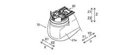
図3に示すように、ロボットアーム21aは、清潔区域において使用されるため、ドレープ70により覆われる。ここで、手術室では、手術により切開した部分および医療機器が病原菌や異物などにより汚染されることを防ぐため、清潔操作が行われる。この清潔操作においては、清潔区域および清潔区域以外の区域である汚染区域が設定される。手術部位は、清潔区域に配置される。操作者Oを含む手術チームのメンバーは、手術中、清潔区域に殺菌されている物体のみが位置するよう配慮し、かつ、汚染区域に位置している物体を清潔区域に移動させるときは、この物体に滅菌処理を施す。同様に、操作者Oを含む手術チームのメンバーがその手を汚染区域に位置させたときは、清潔区域に位置している物体に直接接触する前に、手の滅菌処理を行う。清潔区域において用いられる器具は、滅菌処理が行われる、または、滅菌処理されたドレープ70により覆われる。 As shown in FIG. 3, the
ドレープ70は、ロボットアーム21aと、手術器具40との間に配置される。具体的には、ドレープ70は、アダプタ60と、ロボットアーム21aとの間に配置される。また、ドレープ70は、ロボットアーム21bと、内視鏡50との間に配置される。アダプタ60は、ドレープ70を挟み込むようにして、ロボットアーム21aに取り付けられる。つまり、アダプタ60は、ロボットアーム21aとの間にドレープ70を挟み込むためのドレープアダプタである。また、手術器具40は、ロボットアーム21aにドレープ70を介して取り付けられたアダプタ60に取り付けられる。ロボットアーム21aは、手術器具40のエンドエフェクタ41を駆動させるために、アダプタ60を介して手術器具40に動力を伝達する。 The
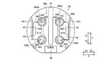
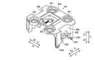
図4に示すように、アダプタ60は、基体61と、複数の駆動伝達部材62aおよび62bと、一対のガイドレール63と、先行ガイドレール64と、電極アレイ65と、アーム係合部66と、を備えている。また、図5に示すように、アダプタ60は、複数のアーム係合穴部67と、複数の位置決孔68とを備えている。駆動伝達部材62aおよび62bは、図4に示すように、駆動伝達部材62aがY2方向側に配置され、駆動伝達部材62bがY1方向側に配置されている。また、アダプタ60は、Z2方向側に配置された第1面60aがロボットアーム21aに取り付けられる。また、アダプタ60は、Z1方向側に配置された第2面60bに手術器具40が取り付けられる。 As shown in FIG. 4, the
手術器具40は、ロボット手術システム100のロボットアーム21aにアダプタ60を介して取り外し可能に接続される手術器具である。図5に示すように、手術器具40のハウジング43のZ2方向側に配置された取付面40aがアダプタ60に取り付けられる。また、手術器具40は、複数の被駆動部材44aおよび44bと、一対の案内溝45と、一対の可動部材46と、先行案内溝47と、電極アレイ48とを備えている。被駆動部材44aおよび44bは、被駆動部材44aがY1方向側に配置され、被駆動部材44bがY2方向側に配置されている。また、手術器具40は、アダプタ60に対する取付面40aを有する基体40bを備えている。 The
図4に示すように、ドレープ70は、本体部71と、取付部72とを備えている。本体部71は、フィルム状に形成されている。取付部72は、樹脂成型により形成されている。取付部72は、ロボットアーム21aおよびアダプタ60が係合する部分に貫通口が設けられている。貫通口は、係合する部分ごとに対応するように設けられていてもよい。また、貫通口は、複数の係合する部分に対応するように設けられていてもよい。 As shown in FIG. 4, the
ロボットアーム21aのアダプタ取付面211には、アダプタ60が取り付けられる。また、ロボットアーム21aは、回転駆動部212と、係合部213と、ボス214とを備えている。 The
図5に示すように、手術器具40の複数の被駆動部材44aおよび44bは、回転駆動されることにより、エンドエフェクタ41を駆動させる。具体的には、シャフト42は、一方端(Y2方向側の端部)が基体40bに接続され、他方端(Y1方向側の端部)にエンドエフェクタ41が接続されている。被駆動部材44aおよび44bとエンドエフェクタ41とは、シャフト42内に通されたワイヤ421(図9参照)により接続されている。つまり、被駆動部材44aおよび44bは、基体40bに回転可能に設けられている。また、被駆動部材44aおよび44bは、エンドエフェクタ41を操作するためのワイヤ421の端部が接続されている。そして、被駆動部材44aおよび44bが回転されることにより、ワイヤ421が引っ張られてエンドエフェクタ41が駆動される。また、被駆動部材44aおよび44bは、ハウジング43内において、シャフト42とギアにより接続されている。つまり、ハウジング43は、基体40bに、複数の被駆動部材44aおよび44bを覆うように設けられる。そして、被駆動部材44aおよび44bが回転されることにより、シャフト42が回転される。なお、ワイヤ421は、特許請求の範囲の「細長要素」の一例である。 As shown in FIG. 5, a plurality of driven
図5に示すように、たとえば、被駆動部材44aは、2つ設けられている。また、被駆動部材44bは、2つ設けられている。1つの被駆動部材44aの回転により、シャフト42が回転される。また、他の3つの被駆動部材44a、44bの回転により、エンドエフェクタ41が駆動される。4つの被駆動部材44a、44bは、X方向に2つ配列され、Y方向に2つ配列されている。 As shown in FIG. 5, for example, two driven
図5および図6に示すように、複数の被駆動部材44aは、それぞれ、アダプタ60に設けられた対応する駆動伝達部材62bに係合する係合部440aを含む。また、複数の被駆動部材44bは、それぞれ、アダプタ60に設けられた対応する駆動伝達部材62aに係合する係合部440bを含む。係合部440aは、スライド挿入方向上流側(Y1方向側)に位置する被駆動部材44aに設けられている。また、係合部440bは、スライド挿入方向下流側(Y2方向側)に位置する被駆動部材44bに設けられている。係合部440aと係合部440bとは異なる形状を有している。 As shown in FIGS. 5 and 6, each of the plurality of driven
具体的には、係合部440aは、第1突起部441と、第1突起部441と独立して設けられた第2突起部442と、第1突起部441および第2突起部442の間に配置された第3突起部443とを有している。また、係合部440bは、第3突起部443を有さずに、第1突起部441と、第2突起部442とを有している。 Specifically, the engaging
一対の案内溝45は、基体40bの取付面40aに設けられている。また、一対の案内溝45は、アダプタ60に設けられた一対のガイドレール63をスライドにより受け入れるために設けられている。案内溝45は、Y方向に沿って延びるように設けられている。また、案内溝45は、X方向に対向するように2つ設けられている。一対の案内溝45は、略平行に設けられている。一対の案内溝45は、アダプタ60の一対のガイドレール63が挿入されてアダプタ60への取り付けを案内する。 The pair of
案内溝45は、少なくとも可動部材46により形成されている。具体的には、案内溝45は、基体40bと可動部材46とにより形成されている。可動部材46は、保持部材49(図9参照)および基体40bに対して移動可能に設けられている。可動部材46は、保持部材49および基体40bに対して移動することにより、アダプタ60との係合が解除されるように構成されている。また、可動部材46を移動させることにより、案内溝45の溝幅を変更可能に構成されている。具体的には、案内溝45は、可動部材46がX方向に移動することにより、幅が変化する。つまり、可動部材46が内側に移動することにより、案内溝45の幅が拡張される。また、可動部材46が外側に移動することにより、案内溝45の幅が縮小される。可動部材46は、案内溝45の幅を狭める方向(外側方向)に向けて付勢されている。 The
これにより、可動部材46を移動させることにより案内溝45の溝幅を変更することができるので、溝幅を大きくした状態の案内溝45をアダプタ60のガイドレール63にスライドさせることにより、アダプタ60に対して手術器具40を容易に着脱することができる。また、アダプタ60のガイドレール63を案内溝45に挿入させた状態で、案内溝45の溝幅を小さくすることにより、アダプタ60に対して手術器具40の基体40bを係合させて固定することができるので、アダプタ60に対して手術器具40を安定して固定することができる。これらの結果、ロボット手術システム100のロボットアーム21aにアダプタ60を介して取り外し可能に接続される手術器具40において、アダプタ60に対して手術器具40を容易に着脱することができ、かつ、アダプタ60に安定して手術器具40を固定することができる。 As a result, the groove width of the
先行案内溝47は、Y方向に沿って延びるように設けられている。また、先行案内溝47は、一対の案内溝45の間に設けられている。また、先行案内溝47は、一対の案内溝45と略平行に延びるように形成されている。また、先行案内溝47は、X方向における取付面40aの略中央に設けられている。 The leading
電極アレイ48は、アダプタ60の電極アレイ65を介してロボットアーム21aに接続される。また、電極アレイ48は、ハウジング43内に設けられた基板に接続されている。つまり、手術器具40をアダプタ60を介してロボットアーム21aに取り付けることにより、手術器具40の基板と、ロボットアーム21aとが接続される。ハウジング43内の基板は、手術器具40の種類や手術器具40の使用回数を管理するためなどに用いられる。 The
図4に示すように、アダプタ60は、ロボット手術システム100のロボットアーム21aに手術器具40を取り外し可能に接続するために設けられている。 As shown in FIG. 4, the
駆動伝達部材62aおよび62bは、基体61に回転可能に設けられている。具体的には、駆動伝達部材62aおよび62bは、Z方向に延びる回転軸線を中心に回転可能に設けられている。駆動伝達部材62aおよび62bは、ロボットアーム21aの回転駆動部212の駆動力を、手術器具40の被駆動部材44bおよび44aに伝達する。駆動伝達部材62aおよび62bは、手術器具40の被駆動部材44bおよび44aに対応するように複数設けられている。また、複数の駆動伝達部材62aおよび62bは、手術器具40の被駆動部材44bおよび44aに対応する位置に各々配置されている。 The
ガイドレール63は、図7に示すように、第2面60bに設けられている。また、ガイドレール63は、Y方向に沿って延びるように設けられている。また、ガイドレール63は、X方向に対向するように2つ設けられている。また、一対のガイドレール63は、それぞれ、手術器具40の取付面40aに略平行に設けられた一対の案内溝45に対応するように設けられている。第2面60bの一対のガイドレール63は、取付面40aの一対の案内溝45をそれぞれ対応させてY方向にスライドさせることにより、複数の駆動伝達部材62aおよび62bの各々と、取付面40aに設けられた複数の被駆動部材44bおよび44aの各々とが対応するように手術器具40を案内するように構成されている。 As shown in FIG. 7, the
先行ガイドレール64は、第2面60bに設けられている。また、先行ガイドレール64は、Y方向に沿って延びるように設けられている。また、先行ガイドレール64は、一対のガイドレール63の間に設けられている。また、先行ガイドレール64は、一対のガイドレール63と略平行に延びるように形成されている。また、先行ガイドレール64は、X方向における第2面60bの略中央に設けられている。また、先行ガイドレール64は、取付面40aに設けられた先行案内溝47に対応して設けられている。つまり、先行ガイドレール64は、一対のガイドレール63よりも先行して手術器具40を案内する。 The leading
電極アレイ65は、手術器具40の電極アレイ48とロボットアーム21aとに接続される。 The
アーム係合部66は、図4および図5に示すように、ロボットアーム21aの係合部213に係合する。具体的には、アーム係合部66は、第1面60aに設けられたアーム係合穴部67に挿入された係合部213と係合する。また、アーム係合部66は、Y方向に移動可能である。アーム係合部66は、付勢部材によりY1方向に付勢されている。アーム係合部66は、Y1方向に移動されることにより、係合部213と係合する。一方アーム係合部66は、Y2方向に移動されることにより、係合部213との係合が解除される。 As shown in FIGS. 4 and 5, the
アーム係合穴部67は、複数設けられている。つまり、アダプタ60は、複数個所の係合により、ロボットアーム21aに固定される。アーム係合穴部67は、たとえば、5つ設けられている。また、複数のアーム係合穴部67は、第1面60aの周方向に沿って、均等に設けられている。 A plurality of
位置決孔68は、第1面60aに設けられている。位置決孔68は、ロボットアーム21aのボス214が嵌り込む。位置決孔68は、複数設けられている。位置決孔68は、第1面60aのY1方向側の端部近傍に設けられている。 The
図7に示すように、ガイドレール63は、レール部631と、張出部632と、爪部633とを含んでいる。レール部631は、Y方向に延びるように形成されている。レール部631は、手術器具40の案内溝45に入り込んで、アダプタ60に対する手術器具40の移動をガイドする。 As shown in FIG. 7, the
張出部632は、レール部631からX方向に張り出すように形成されている。具体的には、X1方向側のガイドレール63の張出部632は、レール部631に対してX1方向側に配置されている。また、X2方向側のガイドレール63の張出部632は、レール部631に対してX2方向側に配置されている。 The overhanging
爪部633は、レール部631からX方向に張り出すように形成されている。具体的には、X1方向側のガイドレール63の爪部633は、レール部631に対してX2方向側に配置されている。また、X2方向側のガイドレール63の爪部633は、レール部631に対してX1方向側に配置されている。つまり、張出部632は、レール部631に対して、爪部633の反対側に設けられている。張出部632は、レール部631に対してX方向における外側に配置されている。爪部633は、レール部631に対してX方向における内側に配置されている。 The
張出部632は、手術器具40の案内溝45に設けられた規制部451(図14参照)に係合する。張出部632が規制部451に係合することにより、アダプタ60に対して手術器具40がZ方向に抜けないように接続される。 The overhanging
爪部633は、手術器具40の案内溝45に設けられた係合穴462(図14参照)に係合する。具体的には、爪部633は、案内溝45を形成する可動部材46の側壁463に設けられた係合穴462に係合する。これにより、爪部633が係合穴462に係合されることによって、ガイドレール63により案内した手術器具40をアダプタ60に対して位置決めして固定することができる。つまり、爪部633が係合穴462に係合することにより、手術器具40がアダプタ60に対してY方向に位置決めされるとともに、アダプタ60に対して手術器具40がY方向に抜けないように固定(ロック)される。また、爪部633は、図14に示すように、X方向に沿って傾斜するように形成されている。 The
図8に示すように、駆動伝達部材62aは、第1部材621と、付勢部材623を介して第1部材621に対して移動可能に設けられた第2部材622と、を含んでいる。第1部材621は、第2部材622が嵌り込む凹部621bと、第2部材622に係合する係合部621cとを有している。第2部材622は、付勢部材623が収容される凹部622aと、第1部材621に係合する係合部622bとを有している。第1部材621と、第2部材622とは、付勢部材623を間に挟んだ状態でZ方向に篏合している。第1部材621は、第2面60b側(Z1方向側)に配置されている。第2部材622は、第1面60a側(Z2方向側)に配置されている。付勢部材623は、第1部材621を第2部材622に対してZ1方向側に付勢している。付勢部材623は、たとえば、圧縮コイルばねにより構成されている。なお、駆動伝達部材62bについて、手術器具40の被駆動部材44aに係合する部分の形状が異なる以外は、駆動伝達部材62aと同様の構成である。なお、付勢部材623は、特許請求の範囲の「第2付勢部材」の一例である。 As shown in FIG. 8, the
第1部材621は、Z方向において、基体61に対して移動可能に配置されている。これにより、手術器具40を一対のガイドレール63に沿って案内してアダプタ60に取り付ける場合に、手術器具40の移動の妨げにならないように駆動伝達部材62bおよび62aの第1部材621をZ方向にくぼむように移動させることができる。つまり、一対の案内溝45は、被駆動部材44aおよび44bと駆動伝達部材62bおよび62aとが係合する方向(Z方向)と交差する方向(Y方向)に一対のガイドレール63を案内するように構成されている。この場合に、手術器具40をガイドレール63に沿って案内してアダプタ60に取り付ける場合に、手術器具40の移動の妨げにならないように駆動伝達部材62bおよび62aの第1部材621を移動させることができる。 The
また、第1部材621は、第2部材622がZ方向の回転軸線を中心に回転することに伴って、回転されるように構成されている。具体的には、第1部材621の内周部に設けられた係合部621cと、第2部材622の外周部に設けられた係合部622bとが、係合するように構成されている。第1部材621の係合部621cは、凹部621bから内側に突出するように形成されている。第2部材622の係合部622bは、第2部材622の外周部から内側に凹むように形成されている。第1部材621の係合部621cと、第2部材622の係合部622bとは、第1部材621が第2部材622に対してZ方向に移動したとしても、互いに係合するように構成されている。つまり、第2部材622に対する第1部材621のZ方向における位置に関わらず、第1部材621は、第2部材622とともに回転されるように構成されている。これにより、第2部材622がロボットアーム21aの回転駆動部212の回転により回転されると、第1部材621も回転される。その結果、第1部材621に係合する手術器具40の被駆動部材44aおよび44bに、ロボットアーム21aの回転駆動部212の回転が伝達される。 Further, the
(可動部材の構成)
図9~図11に示すように、手術器具40の可動部材46は、押圧部461と、係合穴462と、側壁463と、押下げ部464と、一対のガイド部465と、凹部466とを含んでいる。また、可動部材46は、付勢部材467を挟み込むようにして、基体40bおよび保持部材49に取り付けられている。可動部材46は、図14および図15に示すように、付勢部材467により案内溝45の幅を狭める方向(外側方向)に付勢されている。可動部材46は、押圧部461を作業者が押すことにより、案内溝45の幅を広げる方向(内側方向)に移動する。具体的には、X1方向側の可動部材46は、付勢部材467によりX1方向側に付勢されている。また、X1方向側の可動部材46は、X2方向側に押されることにより、付勢力に抗してX2方向側に移動する。また、X2方向側の可動部材46は、付勢部材467によりX2方向側に付勢されている。また、X2方向側の可動部材46は、X1方向側に押されることにより、付勢力に抗してX1方向側に移動する。なお、係合穴462は、特許請求の範囲の「係合部」の一例である。また、付勢部材467は、特許請求の範囲の「第1付勢部材」の一例である。(Composition of movable members)
As shown in FIGS. 9 to 11, the
また、可動部材46は、シャフト42の延びる方向に対して略直交する方向(X方向)に沿って一対設けられている。これにより、一対の可動部材46をアダプタ60に係合させてバランスよく手術器具40を固定することができるので、アダプタ60に対してより安定して手術器具40を固定することができる。 Further, a pair of
押圧部461は、作業者により押圧されて操作されるために設けられている。押圧部461は、図5に示すように、ハウジング43から露出するように、X方向の外側に設けられている。押圧部461は、Y方向に沿った複数の溝が形成されている。これにより、押圧部461の位置を触るだけで認識することが可能であるとともに、操作する手が滑るのを抑制することが可能である。 The
係合穴462は、アダプタ60のガイドレール63に設けられた爪部633に係合する。係合穴462は、図11に示すように、側壁463に設けられている。また、係合穴462は、図14および図15に示すように、側壁463をX方向に貫通するように形成されている。これにより、ガイドレール63により案内した手術器具40をアダプタ60に対して位置決めして固定することができる。 The
また、可動部材46は、図15に示すように、保持部材49および基体40bに対して移動することにより、アダプタ60との係合が解除されるように構成されている。これにより、アダプタ60に対して可動部材46を係合させることにより、アダプタ60に手術器具40を容易に取り付けることができるとともに、アダプタ60に対して手術器具40を安定して固定することができる。また、可動部材46を保持部材49および基体40bに対して移動させることにより、可動部材46とアダプタ60との係合を解除することができるので、アダプタ60から手術器具40を容易に取り外すことができる。これらの結果、ロボット手術システム100のロボットアーム21aにアダプタ60を介して取り外し可能に接続される手術器具40において、アダプタ60に対して手術器具40を容易に着脱することができ、かつ、アダプタ60に安定して手術器具40を固定することができる。 Further, as shown in FIG. 15, the
側壁463は、案内溝45のX方向における内側の壁を構成する。つまり、側壁463は、図14および図15に示すように、基体40bに設けられた規制部451と対向するように配置されている。側壁463と規制部451とにより形成された案内溝45により、ガイドレール63のレール部631を挟み込むようにして、ガイドレール63がガイドされる。 The
規制部451は、案内溝45の基体40b側に、設けられている。規制部451は、Y方向に延びるように形成されている。規制部451は、取付面40aと平行な方向(X方向)に張り出すようにガイドレール63に設けられた張出部632に係合して、被駆動部材44a、44bの回転軸線方向(Z方向)に取付面40aがアダプタ60に対して移動するのを規制する。 The regulating
押下げ部464は、図14および図15に示すように、係合穴462のアダプタ60との係合が解除されるように移動されることにより、駆動伝達部材62a(62b)の第1部材621を被駆動部材44b(44a)と遠ざかる方向に移動させて、駆動伝達部材62a(62b)と被駆動部材44b(44a)との係合を解除する。これにより、可動部材46とアダプタ60との係合を解除する操作と、被駆動部材44b(44a)と駆動伝達部材62a(62b)との係合を解除する操作とを同時に行うことができるので、アダプタ60から手術器具40を取り外す際の作業を容易に行うことができる。 As shown in FIGS. 14 and 15, the push-down
具体的には、押下げ部464は、可動部材46の移動に伴って、被駆動部材44b(44a)と駆動伝達部材62a(62b)とが係合する方向(Z方向)と交差する方向(X方向)に移動されることにより、駆動伝達部材62a(62b)と被駆動部材44b(44a)との係合を解除するように構成されている。 Specifically, the push-down
つまり、押下げ部464は、可動部材46の移動に伴って第1部材621に設けられたテーパ部621aに乗り上げて、第1部材621を被駆動部材44b(44a)と遠ざかる方向(Z2方向)に移動させるように構成されている。 That is, the pushing-down
押下げ部464は、側壁463のZ2方向側部分に対しX方向内側に接続されている。押下げ部464は、XY平面状に延びる板状に形成されている。押下げ部464は、被駆動部材44b(44a)に対応する部分に切り欠きが設けられている。 The
一対のガイド部465は、可動部材46のX方向の移動をガイドするように構成されている。ガイド部465は、Y方向に沿って一対設けられている。また、一対のガイド部465は、X方向に延びるように形成されている。具体的には、ガイド部465は、押圧部461の内面から内側に延びるように形成されている。ガイド部465は、図13に示すように、保持部材49により上方への移動が規制され、基体40bにより下方への移動が規制される。 The pair of
凹部466は、図14に示すように、付勢部材467が嵌りこむように構成されている。凹部466は、押圧部461の内面から外側に窪むように設けられている。また、凹部466は、Z方向において押圧部461の中心近傍に設けられている。また、凹部466は、Y方向において押圧部461の中心近傍に設けられている。これにより、付勢部材467の付勢力が、押圧部461の中心に作用される。 As shown in FIG. 14, the
付勢部材467は、可動部材46を基体40bの外周部方向に向けて付勢するように構成されている。付勢部材467の内側の端部は、保持部材49により保持されている。これにより、付勢部材467のX方向内側への移動が規制されている。この結果、被駆動部材44b(44a)を保持する保持部材49により付勢部材467を保持することができるので、付勢部材467を保持するための専用の部材を別個に設ける必要がない。これにより、部品点数が増加するのを抑制することができる。付勢部材467の外側の端部は、押圧部461の内側の凹部466に嵌りこんでいる。付勢部材467は、たとえば、圧縮コイルばねにより構成されている。 The urging
図9に示すように、基体40bには、外部から係合穴462(係合部)に通じる開口部40cが設けられている。これにより、押圧部461の操作が困難である場合でも、開口部40cを介して係合穴462を移動させることができるので、係合穴462のアダプタ60との係合を解除させることができる。 As shown in FIG. 9, the
(保持部材の構成)
図12に示すように、手術器具40の保持部材49は、上面49aと、上面49aに接続された一対の側面49bと、を含んでいる。また、保持部材49の上面49aには、被駆動部材44aおよび44bを回転可能に支持する支持部491が設けられている。また、保持部材49の側面49bには、突起部492と、規制部493と、爪494とが設けられている。保持部材49は、樹脂により形成されている。(Structure of holding member)
As shown in FIG. 12, the holding
保持部材49は、一方端が基体40bにより保持された複数の被駆動部材44aおよび44bの他方端(Z1方向側の端部)を回転可能に保持するように構成されている。具体的には、図13に示すように、保持部材49は、基体40bに対して係合するとともに、被駆動部材44aおよび44bの端部を例えばeリングなどの止め輪445により保持することにより、基体40bに固定されている。これにより、保持部材49を基体40bに対して安定して固定することができるので、保持部材49により被駆動部材44aおよび44bを安定して保持することができる。 The holding
詳しくは、被駆動部材44a(44b)の軸444を、Z2方向から基体40bの貫通孔40d(図14参照)に、軸受を介して挿入する。そして、ワイヤ421を巻きまわす部材を軸444に取り付け、ワイヤ421を取り付ける。その後、保持部材49を、基体40bに対して係合させる。具体的には、保持部材49の複数の爪494を基体40bに対してスナップフィットにより係合させる。この際に、被駆動部材44a(44b)のZ1方向側の先端が、軸受を介して保持部材49の支持部491に挿入される。そして、留め具としての止め輪445が被駆動部材44a(44b)の軸444の外周に設けられた溝444aに嵌りこんで被駆動部材44a(44b)の端部が保持される。これにより、保持部材49が、基体40bに固定されるとともに、被駆動部材44a(44b)のZ1方向側の端部が回転可能に支持される。 Specifically, the
支持部491は、被駆動部材44aおよび44bの位置に対応する位置に設けられている。支持部491には、Z方向に貫通する貫通孔が形成されている。支持部491は、一方端が基体40bにより保持された複数の被駆動部材44aおよび44bの他方端(Z1方向側の端部)を回転可能に保持するように構成されている。 The
突起部492は、可動部材46側(外側)に突出するように設けられている。突起部492には、付勢部材467が挿入されている。これにより、保持部材49に設けられた突起部492により付勢部材467を容易に保持することができる。 The
規制部493は、可動部材46のガイド部465のZ1方向への移動を規制する。 The restricting
爪494は、基体40bにスナップフィットにより係合する。 The
(ロボットアームへの手術器具の取り付け)
図16~図18を参照して、一実施形態によるロボットアーム21aへの手術器具40の取り付けについて説明する。(Attachment of surgical instruments to the robot arm)
16 to 18, the attachment of the
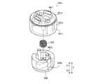
図16および図17に示すように、ロボットアーム21aをドレープ70で覆った状態で、ロボットアーム21aにアダプタ60を取り付ける。アダプタ60は、ロボットアーム21aに対してZ方向に移動させて、ロボットアーム21aに取り付けられる。図18に示すように、ロボットアーム21aに取り付けられたアダプタ60に対して手術器具40を取り付ける。手術器具40は、アダプタ60のガイドレール63に沿ってY1方向に移動させて、アダプタ60に取り付けられる。これにより、手術器具40がアダプタ60を介してロボットアーム21aに取り付けられる。 As shown in FIGS. 16 and 17, the
手術器具40をロボットアーム21aから取り外す場合は、手術器具40の可動部材46の押圧部461を押しながら、手術器具40をY2方向にスライド移動させることにより、手術器具40がアダプタ60から外される。 When removing the
(変形例)
なお、今回開示された実施形態は、すべての点で例示であって制限的なものではないと考えられるべきである。本発明の範囲は、上記した実施形態の説明ではなく特許請求の範囲によって示され、さらに特許請求の範囲と均等の意味および範囲内でのすべての変更(変形例)が含まれる。(Modification example)
It should be noted that the embodiments disclosed this time are exemplary in all respects and are not considered to be restrictive. The scope of the present invention is shown by the scope of claims rather than the description of the above-described embodiment, and further includes all modifications (modifications) within the meaning and scope equivalent to the scope of claims.
たとえば、上記実施形態では、アダプタの第2面に沿って手術器具をシャフトの延びる方向にスライド移動させることにより、着脱する構成の例を示したが、本発明はこれに限られない。本発明では、アダプタの第2面に沿って手術器具をシャフトの延びる方向と交差する方向にスライド移動させることにより、着脱させてもよい。 For example, in the above embodiment, an example of a configuration in which a surgical instrument is slid and moved in a direction in which a shaft extends along a second surface of an adapter is shown, but the present invention is not limited to this. In the present invention, the surgical instrument may be attached / detached by sliding the surgical instrument along the second surface of the adapter in a direction intersecting the extending direction of the shaft.
また、上記実施形態では、可動部材と基体とにより案内溝が形成されている構成の例を示したが、本発明はこれに限られない。本発明では、少なくとも可動部材によりアダプタに設けられたガイドレールをスライドにより受け入れるための案内溝が形成されていればよい。 Further, in the above embodiment, an example of the configuration in which the guide groove is formed by the movable member and the substrate is shown, but the present invention is not limited to this. In the present invention, at least a guide groove for receiving the guide rail provided on the adapter by a movable member by a slide may be formed.
また、上記実施形態では、可動部材がシャフトの延びる方向と交差する方向に移動可能な構成の例を示したが、本発明はこれに限られない。本発明では、可動部材がシャフトの延びる方向に移動可能であってもよい。また、可動部材は、被駆動部材の回転軸線方向に移動可能であってもよい。 Further, in the above embodiment, an example of the configuration in which the movable member can move in the direction intersecting the extending direction of the shaft is shown, but the present invention is not limited to this. In the present invention, the movable member may be movable in the extending direction of the shaft. Further, the movable member may be movable in the direction of the rotation axis of the driven member.
また、上記実施形態では、平面視において手術器具の取付面が略円形状を有する構成の例を示したが、本発明はこれに限られない。本発明では、手術器具の取付面の平面視における形状は略円形状でなくてもよい。たとえば、手術器具の取付面は、平面視において矩形形状を有していてもよい。 Further, in the above embodiment, an example of a configuration in which the mounting surface of the surgical instrument has a substantially circular shape in a plan view is shown, but the present invention is not limited to this. In the present invention, the shape of the mounting surface of the surgical instrument in a plan view does not have to be substantially circular. For example, the mounting surface of the surgical instrument may have a rectangular shape in a plan view.
また、上記実施形態では、手術器具の基体に4つの被駆動部材が設けられている構成の例を示したが、本発明はこれに限られない。本発明では、手術器具の基体に4つ以外の複数の被駆動部材が設けられていてもよい。 Further, in the above embodiment, an example of a configuration in which four driven members are provided on a substrate of a surgical instrument is shown, but the present invention is not limited to this. In the present invention, a plurality of driven members other than the four may be provided on the base of the surgical instrument.
また、上記実施形態では、アダプタとドレープとが別体に設けられている構成の例を示したが、本発明はこれに限られない。本発明では、アダプタとドレープとが一体的に設けられている構成でもよい。 Further, in the above embodiment, an example of a configuration in which the adapter and the drape are separately provided is shown, but the present invention is not limited to this. In the present invention, the adapter and the drape may be integrally provided.
21a:ロボットアーム、40:手術器具、40a:取付面、40b:基体、41:エンドエフェクタ(処置具)、42:シャフト、44a、44b:被駆動部材、45:案内溝、46:可動部材、49:保持部材、60:アダプタ、62a、62b:駆動伝達部材、63:ガイドレール、70:ドレープ、100:ロボット手術システム、421:ワイヤ(細長要素)、444:軸、444a:溝、445:止め輪(留め具)、461:押圧部、462:係合穴(係合部)、464:押下げ部、467:付勢部材(第1付勢部材)、492:突起部、621:第1部材、622:第2部材、623:付勢部材(第2付勢部材) 21a: Robot arm, 40: Surgical instrument, 40a: Mounting surface, 40b: Base, 41: End effector (treatment tool), 42: Shaft, 44a, 44b: Driven member, 45: Guide groove, 46: Movable member, 49: Retaining member, 60: Adapter, 62a, 62b: Drive transmission member, 63: Guide rail, 70: Drape, 100: Robotic surgery system, 421: Wire (elongated element), 444: Shaft, 444a: Groove, 445: Retaining ring (fastener), 461: pressing part, 462: engaging hole (engaging part), 464: pushing down part, 467: urging member (first urging member), 492: protrusion, 621: first 1 member, 622: 2nd member, 623: urging member (2nd urging member)
Claims (10)
Translated fromJapanese前記アダプタに対する取付面を有する基体と、
一方端が前記基体に接続された細長形状のシャフトと、
前記シャフトの他方端に接続された処置具と、
前記基体に回転可能に設けられ、前記処置具を操作するための細長要素の端部が接続された複数の被駆動部材と、
一方端が前記基体により保持された複数の前記被駆動部材の他方端を回転可能に保持する保持部材と、
前記保持部材および前記基体に対して移動可能に設けられ、前記アダプタに係合する可動部材と、を備え、
前記可動部材は、前記保持部材および前記基体に対して移動することにより、前記アダプタとの係合が解除されるように構成されており、
前記可動部材を前記基体の外周部方向に向けて付勢する第1付勢部材をさらに備え、
前記第1付勢部材は、前記保持部材により保持されている、手術器具。A surgical instrument that is detachably connected to the robot arm of a robotic surgery system via an adapter.
A substrate having a mounting surface for the adapter and
An elongated shaft whose one end is connected to the substrate,
A treatment tool connected to the other end of the shaft and
A plurality of driven members rotatably provided on the substrate and to which the ends of elongated elements for operating the treatment tool are connected.
A holding member whose one end rotatably holds the other end of the plurality of driven members held by the substrate,
A movable member that is movably provided with respect to the holding member and the substrateand engages with the adapter.
The movable member is configured to be disengaged from the adapter by moving with respect to the holding member and the substrate.
Further, a first urging member for urging the movable member toward the outer peripheral portion of the substrate is provided.
The first urging member is a surgical instrument held by the holding member .
前記案内溝は、前記可動部材を移動させることにより、溝幅を変更可能に構成されている、請求項1に記載の手術器具。At least the movable member forms a guide groove for receiving the guide rail provided in the adapter by a slide.
The surgical instrument according to claim 1, wherein the guide groove is configured so that the groove width can be changed by moving the movable member.
前記第1付勢部材は、圧縮コイルばねを含み、
前記突起部には、前記圧縮コイルばねが挿入されている、請求項1または2に記載の手術器具。The holding member includes a protrusion protruding toward the movable member, and the holding member includes a protrusion.
The first urging member includes a compression coil spring.
The surgical instrument according to claim1 or 2 , wherein the compression coil spring is inserted in the protrusion.
前記アダプタに対する取付面を有する基体と、
一方端が前記基体に接続された細長形状のシャフトと、
前記シャフトの他方端に接続された処置具と、
前記基体に回転可能に設けられ、前記処置具を操作するための細長要素の端部が接続された複数の被駆動部材と、
一方端が前記基体により保持された複数の前記被駆動部材の他方端を回転可能に保持する保持部材と、
前記保持部材および前記基体に対して移動可能に設けられ、前記アダプタに係合する可動部材と、を備え、
前記可動部材は、前記保持部材および前記基体に対して移動することにより、前記アダプタとの係合が解除されるように構成されており、
前記保持部材は、前記基体に対して係合するとともに、前記被駆動部材の端部を留め具により保持することにより、前記基体に固定されている、手術器具。A surgical instrument that is detachably connected to the robot arm of a robotic surgery system via an adapter.
A substrate having a mounting surface for the adapter and
An elongated shaft whose one end is connected to the substrate,
A treatment tool connected to the other end of the shaft and
A plurality of driven members rotatably provided on the substrate and to which the ends of elongated elements for operating the treatment tool are connected.
A holding member whose one end rotatably holds the other end of the plurality of driven members held by the substrate,
A movable member that is movably provided with respect to the holding member and the substrate and engages with the adapter.
The movable member is configured to be disengaged from the adapter by moving with respect to the holding member and the substrate.
Asurgical instrument in which the holding member is fixed to the base by engaging with the base and holding the end of the driven member with a fastener.
前記アダプタに対する取付面を有する基体と、
一方端が前記基体に接続された細長形状のシャフトと、
前記シャフトの他方端に接続された処置具と、
前記基体に回転可能に設けられ、前記処置具を操作するための細長要素の端部が接続された複数の被駆動部材と、
一方端が前記基体により保持された複数の前記被駆動部材の他方端を回転可能に保持する保持部材と、
前記保持部材および前記基体に対して移動可能に設けられ、前記アダプタに係合する可動部材と、を備え、
前記可動部材は、前記保持部材および前記基体に対して移動することにより、前記アダプタとの係合が解除されるように構成されており、
前記可動部材は、押圧操作される押圧部と、前記アダプタに係合する係合部とを含み、
前記基体には、外部から前記係合部に通じる開口部が設けられている、手術器具。A surgical instrument that is detachably connected to the robot arm of a robotic surgery system via an adapter.
A substrate having a mounting surface for the adapter and
An elongated shaft whose one end is connected to the substrate,
A treatment tool connected to the other end of the shaft and
A plurality of driven members rotatably provided on the substrate and to which the ends of elongated elements for operating the treatment tool are connected.
A holding member whose one end rotatably holds the other end of the plurality of driven members held by the substrate,
A movable member that is movably provided with respect to the holding member and the substrate and engages with the adapter.
The movable member is configured to be disengaged from the adapter by moving with respect to the holding member and the substrate.
The movable member includes a pressing portion to be pressed and an engaging portion engaging with the adapter.
Asurgical instrument provided with an opening in the substrate leading to the engaging portion from the outside.
前記アダプタに対する取付面を有する基体と、
一方端が前記基体に接続された細長形状のシャフトと、
前記シャフトの他方端に接続された処置具と、
前記基体に回転可能に設けられ、前記処置具を操作するための細長要素の端部が接続された複数の被駆動部材と、
一方端が前記基体により保持された複数の前記被駆動部材の他方端を回転可能に保持する保持部材と、
前記保持部材および前記基体に対して移動可能に設けられ、前記アダプタに係合する可動部材と、を備え、
前記可動部材は、前記保持部材および前記基体に対して移動することにより、前記アダプタとの係合が解除されるように構成されており、
前記アダプタは、第1部材と、第2付勢部材を介して前記第1部材に対して移動可能に設けられた第2部材とを有し、前記被駆動部材に係合するように設けられた駆動伝達部材を含み、
前記可動部材は、前記アダプタとの係合が解除されるように移動されることにより、前記駆動伝達部材の前記第1部材を前記被駆動部材と遠ざかる方向に移動させて、前記駆動伝達部材と前記被駆動部材との係合を解除する押下げ部を含む、手術器具。A surgical instrument that is detachably connected to the robot arm of a robotic surgery system via an adapter.
A substrate having a mounting surface for the adapter and
An elongated shaft whose one end is connected to the substrate,
A treatment tool connected to the other end of the shaft and
A plurality of driven members rotatably provided on the substrate and to which the ends of elongated elements for operating the treatment tool are connected.
A holding member whose one end rotatably holds the other end of the plurality of driven members held by the substrate,
A movable member that is movably provided with respect to the holding member and the substrate and engages with the adapter.
The movable member is configured to be disengaged from the adapter by moving with respect to the holding member and the substrate.
The adapter has a first member and a second member movably provided with respect to the first member via a second urging member, and is provided so as to engage with the driven member. Including the drive transmission member
The movable member is moved so as to be disengaged from the adapter, whereby the first member of the drive transmission member is moved in a direction away from the driven member, and the drive transmission member and the drive transmission member are moved away from the driven member. Asurgical instrument comprising a push-down portion that disengages engagement with the driven member.
Priority Applications (3)
| Application Number | Priority Date | Filing Date | Title |
|---|---|---|---|
| JP2019177054AJP7046880B2 (en) | 2019-09-27 | 2019-09-27 | Surgical instruments |
| EP20196266.9AEP3797726B1 (en) | 2019-09-27 | 2020-09-15 | Surgical instrument, assembly including adaptor and surgical instrument, and robotic surgical system |
| US17/023,428US11642187B2 (en) | 2019-09-27 | 2020-09-17 | Surgical instrument, assembly including adaptor and surgical instrument, and robotic surgical system |
Applications Claiming Priority (1)
| Application Number | Priority Date | Filing Date | Title |
|---|---|---|---|
| JP2019177054AJP7046880B2 (en) | 2019-09-27 | 2019-09-27 | Surgical instruments |
Publications (2)
| Publication Number | Publication Date |
|---|---|
| JP2021052906A JP2021052906A (en) | 2021-04-08 |
| JP7046880B2true JP7046880B2 (en) | 2022-04-04 |
Family
ID=72521427
Family Applications (1)
| Application Number | Title | Priority Date | Filing Date |
|---|---|---|---|
| JP2019177054AActiveJP7046880B2 (en) | 2019-09-27 | 2019-09-27 | Surgical instruments |
Country Status (3)
| Country | Link |
|---|---|
| US (1) | US11642187B2 (en) |
| EP (1) | EP3797726B1 (en) |
| JP (1) | JP7046880B2 (en) |
Families Citing this family (4)
| Publication number | Priority date | Publication date | Assignee | Title |
|---|---|---|---|---|
| EP4021333A4 (en)* | 2019-08-28 | 2023-11-29 | Covidien LP | STERILE INTERFACE MODULE FOR ROBOTIC SURGICAL SETS |
| EP4360582B1 (en)* | 2021-07-14 | 2025-07-02 | Cornerstone Technology (Shenzhen) Limited | Connecting structures and surgical robot |
| US20230049257A1 (en)* | 2021-08-12 | 2023-02-16 | Cmr Surgical Limited | Surgical robot arm and instrument detachment |
| US20250235088A1 (en)* | 2024-01-24 | 2025-07-24 | Verb Surgical Inc. | Tool drive adaptor for robotic surgical instrument |
Citations (2)
| Publication number | Priority date | Publication date | Assignee | Title |
|---|---|---|---|---|
| JP2009045428A (en) | 2007-07-25 | 2009-03-05 | Terumo Corp | Operating mechanism, medical manipulator and surgical robot system |
| JP2017512525A (en) | 2014-03-17 | 2017-05-25 | インテュイティブ サージカル オペレーションズ, インコーポレイテッド | Aseptic barrier between surgical instrument and remotely operated actuator |
Family Cites Families (6)
| Publication number | Priority date | Publication date | Assignee | Title |
|---|---|---|---|---|
| US8206406B2 (en) | 1996-12-12 | 2012-06-26 | Intuitive Surgical Operations, Inc. | Disposable sterile surgical adaptor |
| US9002518B2 (en)* | 2003-06-30 | 2015-04-07 | Intuitive Surgical Operations, Inc. | Maximum torque driving of robotic surgical tools in robotic surgical systems |
| CN113729964B (en)* | 2015-04-27 | 2024-08-02 | 直观外科手术操作公司 | Surgical instrument housing and related systems and methods |
| EP3463143A4 (en)* | 2016-05-26 | 2020-01-22 | Covidien LP | ROBOTIC SURGICAL ARRANGEMENTS |
| US11484310B2 (en)* | 2017-06-28 | 2022-11-01 | Cilag Gmbh International | Surgical instrument comprising a shaft including a closure tube profile |
| JP6772226B2 (en)* | 2018-08-28 | 2020-10-21 | 株式会社メディカロイド | Surgical instruments |
- 2019
- 2019-09-27JPJP2019177054Apatent/JP7046880B2/enactiveActive
- 2020
- 2020-09-15EPEP20196266.9Apatent/EP3797726B1/enactiveActive
- 2020-09-17USUS17/023,428patent/US11642187B2/enactiveActive
Patent Citations (2)
| Publication number | Priority date | Publication date | Assignee | Title |
|---|---|---|---|---|
| JP2009045428A (en) | 2007-07-25 | 2009-03-05 | Terumo Corp | Operating mechanism, medical manipulator and surgical robot system |
| JP2017512525A (en) | 2014-03-17 | 2017-05-25 | インテュイティブ サージカル オペレーションズ, インコーポレイテッド | Aseptic barrier between surgical instrument and remotely operated actuator |
Also Published As
| Publication number | Publication date |
|---|---|
| US11642187B2 (en) | 2023-05-09 |
| JP2021052906A (en) | 2021-04-08 |
| US20210093403A1 (en) | 2021-04-01 |
| EP3797726B1 (en) | 2025-01-15 |
| EP3797726A1 (en) | 2021-03-31 |
Similar Documents
| Publication | Publication Date | Title |
|---|---|---|
| JP6772226B2 (en) | Surgical instruments | |
| US11583352B2 (en) | Endoscope adaptor, surgical system including the same, and method of attaching endoscope to robot arm through the same | |
| JP7046880B2 (en) | Surgical instruments | |
| EP3616642B1 (en) | Adaptor and method of attaching surgical instrument to robot arm through adaptor | |
| JP7096935B2 (en) | How to install sterile drapes and surgical instruments | |
| JP6971284B2 (en) | Adapter set and adapter | |
| JP7035229B2 (en) | adapter | |
| JP6745306B2 (en) | Adapter and connection method | |
| EP3714829A1 (en) | Adaptor | |
| US12082891B2 (en) | Robotic surgical apparatus, surgical instrument, and method of attaching surgical instrument to robot arm | |
| US11266386B2 (en) | Adapter, robotic surgical system, and adapter attaching method | |
| US20220117691A1 (en) | Adaptor, method of detaching adaptor from robot arm, and robotic surgical system | |
| EP3811883A1 (en) | Surgical instrument |
Legal Events
| Date | Code | Title | Description |
|---|---|---|---|
| A521 | Request for written amendment filed | Free format text:JAPANESE INTERMEDIATE CODE: A523 Effective date:20201021 | |
| A621 | Written request for application examination | Free format text:JAPANESE INTERMEDIATE CODE: A621 Effective date:20201021 | |
| A977 | Report on retrieval | Free format text:JAPANESE INTERMEDIATE CODE: A971007 Effective date:20210818 | |
| A131 | Notification of reasons for refusal | Free format text:JAPANESE INTERMEDIATE CODE: A131 Effective date:20210907 | |
| A521 | Request for written amendment filed | Free format text:JAPANESE INTERMEDIATE CODE: A523 Effective date:20211101 | |
| TRDD | Decision of grant or rejection written | ||
| A01 | Written decision to grant a patent or to grant a registration (utility model) | Free format text:JAPANESE INTERMEDIATE CODE: A01 Effective date:20220322 | |
| A61 | First payment of annual fees (during grant procedure) | Free format text:JAPANESE INTERMEDIATE CODE: A61 Effective date:20220323 | |
| R150 | Certificate of patent or registration of utility model | Ref document number:7046880 Country of ref document:JP Free format text:JAPANESE INTERMEDIATE CODE: R150 | |
| R250 | Receipt of annual fees | Free format text:JAPANESE INTERMEDIATE CODE: R250 |