JP7046590B2 - Two-dimensional pulmonary vein display - Google Patents
Two-dimensional pulmonary vein displayDownload PDFInfo
- Publication number
- JP7046590B2 JP7046590B2JP2017244771AJP2017244771AJP7046590B2JP 7046590 B2JP7046590 B2JP 7046590B2JP 2017244771 AJP2017244771 AJP 2017244771AJP 2017244771 AJP2017244771 AJP 2017244771AJP 7046590 B2JP7046590 B2JP 7046590B2
- Authority
- JP
- Japan
- Prior art keywords
- image
- ablation
- map
- processor
- lumen
- Prior art date
- Legal status (The legal status is an assumption and is not a legal conclusion. Google has not performed a legal analysis and makes no representation as to the accuracy of the status listed.)
- Active
Links
Images


Classifications
- A—HUMAN NECESSITIES
- A61—MEDICAL OR VETERINARY SCIENCE; HYGIENE
- A61B—DIAGNOSIS; SURGERY; IDENTIFICATION
- A61B18/00—Surgical instruments, devices or methods for transferring non-mechanical forms of energy to or from the body
- A61B18/04—Surgical instruments, devices or methods for transferring non-mechanical forms of energy to or from the body by heating
- A61B18/12—Surgical instruments, devices or methods for transferring non-mechanical forms of energy to or from the body by heating by passing a current through the tissue to be heated, e.g. high-frequency current
- A—HUMAN NECESSITIES
- A61—MEDICAL OR VETERINARY SCIENCE; HYGIENE
- A61B—DIAGNOSIS; SURGERY; IDENTIFICATION
- A61B5/00—Measuring for diagnostic purposes; Identification of persons
- A61B5/74—Details of notification to user or communication with user or patient; User input means
- A61B5/742—Details of notification to user or communication with user or patient; User input means using visual displays
- A61B5/7425—Displaying combinations of multiple images regardless of image source, e.g. displaying a reference anatomical image with a live image
- A—HUMAN NECESSITIES
- A61—MEDICAL OR VETERINARY SCIENCE; HYGIENE
- A61B—DIAGNOSIS; SURGERY; IDENTIFICATION
- A61B18/00—Surgical instruments, devices or methods for transferring non-mechanical forms of energy to or from the body
- A61B18/04—Surgical instruments, devices or methods for transferring non-mechanical forms of energy to or from the body by heating
- A61B18/12—Surgical instruments, devices or methods for transferring non-mechanical forms of energy to or from the body by heating by passing a current through the tissue to be heated, e.g. high-frequency current
- A61B18/14—Probes or electrodes therefor
- A61B18/1492—Probes or electrodes therefor having a flexible, catheter-like structure, e.g. for heart ablation
- A—HUMAN NECESSITIES
- A61—MEDICAL OR VETERINARY SCIENCE; HYGIENE
- A61B—DIAGNOSIS; SURGERY; IDENTIFICATION
- A61B5/00—Measuring for diagnostic purposes; Identification of persons
- A61B5/0033—Features or image-related aspects of imaging apparatus, e.g. for MRI, optical tomography or impedance tomography apparatus; Arrangements of imaging apparatus in a room
- A61B5/0036—Features or image-related aspects of imaging apparatus, e.g. for MRI, optical tomography or impedance tomography apparatus; Arrangements of imaging apparatus in a room including treatment, e.g., using an implantable medical device, ablating, ventilating
- A—HUMAN NECESSITIES
- A61—MEDICAL OR VETERINARY SCIENCE; HYGIENE
- A61B—DIAGNOSIS; SURGERY; IDENTIFICATION
- A61B5/00—Measuring for diagnostic purposes; Identification of persons
- A61B5/0059—Measuring for diagnostic purposes; Identification of persons using light, e.g. diagnosis by transillumination, diascopy, fluorescence
- A61B5/0082—Measuring for diagnostic purposes; Identification of persons using light, e.g. diagnosis by transillumination, diascopy, fluorescence adapted for particular medical purposes
- A61B5/0084—Measuring for diagnostic purposes; Identification of persons using light, e.g. diagnosis by transillumination, diascopy, fluorescence adapted for particular medical purposes for introduction into the body, e.g. by catheters
- A—HUMAN NECESSITIES
- A61—MEDICAL OR VETERINARY SCIENCE; HYGIENE
- A61B—DIAGNOSIS; SURGERY; IDENTIFICATION
- A61B5/00—Measuring for diagnostic purposes; Identification of persons
- A61B5/02—Detecting, measuring or recording for evaluating the cardiovascular system, e.g. pulse, heart rate, blood pressure or blood flow
- A61B5/02007—Evaluating blood vessel condition, e.g. elasticity, compliance
- A—HUMAN NECESSITIES
- A61—MEDICAL OR VETERINARY SCIENCE; HYGIENE
- A61B—DIAGNOSIS; SURGERY; IDENTIFICATION
- A61B5/00—Measuring for diagnostic purposes; Identification of persons
- A61B5/48—Other medical applications
- A61B5/4836—Diagnosis combined with treatment in closed-loop systems or methods
- A—HUMAN NECESSITIES
- A61—MEDICAL OR VETERINARY SCIENCE; HYGIENE
- A61B—DIAGNOSIS; SURGERY; IDENTIFICATION
- A61B90/00—Instruments, implements or accessories specially adapted for surgery or diagnosis and not covered by any of the groups A61B1/00 - A61B50/00, e.g. for luxation treatment or for protecting wound edges
- A61B90/36—Image-producing devices or illumination devices not otherwise provided for
- A61B90/361—Image-producing devices, e.g. surgical cameras
- A—HUMAN NECESSITIES
- A61—MEDICAL OR VETERINARY SCIENCE; HYGIENE
- A61B—DIAGNOSIS; SURGERY; IDENTIFICATION
- A61B90/00—Instruments, implements or accessories specially adapted for surgery or diagnosis and not covered by any of the groups A61B1/00 - A61B50/00, e.g. for luxation treatment or for protecting wound edges
- A61B90/36—Image-producing devices or illumination devices not otherwise provided for
- A61B90/37—Surgical systems with images on a monitor during operation
- G—PHYSICS
- G06—COMPUTING OR CALCULATING; COUNTING
- G06T—IMAGE DATA PROCESSING OR GENERATION, IN GENERAL
- G06T11/00—2D [Two Dimensional] image generation
- G—PHYSICS
- G06—COMPUTING OR CALCULATING; COUNTING
- G06T—IMAGE DATA PROCESSING OR GENERATION, IN GENERAL
- G06T11/00—2D [Two Dimensional] image generation
- G06T11/003—Reconstruction from projections, e.g. tomography
- G—PHYSICS
- G06—COMPUTING OR CALCULATING; COUNTING
- G06T—IMAGE DATA PROCESSING OR GENERATION, IN GENERAL
- G06T11/00—2D [Two Dimensional] image generation
- G06T11/003—Reconstruction from projections, e.g. tomography
- G06T11/008—Specific post-processing after tomographic reconstruction, e.g. voxelisation, metal artifact correction
- G—PHYSICS
- G06—COMPUTING OR CALCULATING; COUNTING
- G06T—IMAGE DATA PROCESSING OR GENERATION, IN GENERAL
- G06T11/00—2D [Two Dimensional] image generation
- G06T11/60—Editing figures and text; Combining figures or text
- G—PHYSICS
- G06—COMPUTING OR CALCULATING; COUNTING
- G06T—IMAGE DATA PROCESSING OR GENERATION, IN GENERAL
- G06T15/00—3D [Three Dimensional] image rendering
- G06T15/08—Volume rendering
- G—PHYSICS
- G06—COMPUTING OR CALCULATING; COUNTING
- G06T—IMAGE DATA PROCESSING OR GENERATION, IN GENERAL
- G06T19/00—Manipulating 3D models or images for computer graphics
- G—PHYSICS
- G06—COMPUTING OR CALCULATING; COUNTING
- G06T—IMAGE DATA PROCESSING OR GENERATION, IN GENERAL
- G06T7/00—Image analysis
- G06T7/0002—Inspection of images, e.g. flaw detection
- G06T7/0012—Biomedical image inspection
- G06T7/0014—Biomedical image inspection using an image reference approach
- G—PHYSICS
- G06—COMPUTING OR CALCULATING; COUNTING
- G06T—IMAGE DATA PROCESSING OR GENERATION, IN GENERAL
- G06T7/00—Image analysis
- G06T7/70—Determining position or orientation of objects or cameras
- G06T7/73—Determining position or orientation of objects or cameras using feature-based methods
- G06T7/74—Determining position or orientation of objects or cameras using feature-based methods involving reference images or patches
- A—HUMAN NECESSITIES
- A61—MEDICAL OR VETERINARY SCIENCE; HYGIENE
- A61B—DIAGNOSIS; SURGERY; IDENTIFICATION
- A61B18/00—Surgical instruments, devices or methods for transferring non-mechanical forms of energy to or from the body
- A61B2018/00315—Surgical instruments, devices or methods for transferring non-mechanical forms of energy to or from the body for treatment of particular body parts
- A61B2018/00345—Vascular system
- A61B2018/00351—Heart
- A61B2018/00375—Ostium, e.g. ostium of pulmonary vein or artery
- A—HUMAN NECESSITIES
- A61—MEDICAL OR VETERINARY SCIENCE; HYGIENE
- A61B—DIAGNOSIS; SURGERY; IDENTIFICATION
- A61B18/00—Surgical instruments, devices or methods for transferring non-mechanical forms of energy to or from the body
- A61B2018/00571—Surgical instruments, devices or methods for transferring non-mechanical forms of energy to or from the body for achieving a particular surgical effect
- A61B2018/00577—Ablation
- A—HUMAN NECESSITIES
- A61—MEDICAL OR VETERINARY SCIENCE; HYGIENE
- A61B—DIAGNOSIS; SURGERY; IDENTIFICATION
- A61B18/00—Surgical instruments, devices or methods for transferring non-mechanical forms of energy to or from the body
- A61B2018/00571—Surgical instruments, devices or methods for transferring non-mechanical forms of energy to or from the body for achieving a particular surgical effect
- A61B2018/00589—Coagulation
- A—HUMAN NECESSITIES
- A61—MEDICAL OR VETERINARY SCIENCE; HYGIENE
- A61B—DIAGNOSIS; SURGERY; IDENTIFICATION
- A61B18/00—Surgical instruments, devices or methods for transferring non-mechanical forms of energy to or from the body
- A61B2018/00636—Sensing and controlling the application of energy
- A61B2018/00773—Sensed parameters
- A61B2018/00779—Power or energy
- A—HUMAN NECESSITIES
- A61—MEDICAL OR VETERINARY SCIENCE; HYGIENE
- A61B—DIAGNOSIS; SURGERY; IDENTIFICATION
- A61B18/00—Surgical instruments, devices or methods for transferring non-mechanical forms of energy to or from the body
- A61B2018/00636—Sensing and controlling the application of energy
- A61B2018/00773—Sensed parameters
- A61B2018/00886—Duration
- A—HUMAN NECESSITIES
- A61—MEDICAL OR VETERINARY SCIENCE; HYGIENE
- A61B—DIAGNOSIS; SURGERY; IDENTIFICATION
- A61B90/00—Instruments, implements or accessories specially adapted for surgery or diagnosis and not covered by any of the groups A61B1/00 - A61B50/00, e.g. for luxation treatment or for protecting wound edges
- A61B90/06—Measuring instruments not otherwise provided for
- A61B2090/064—Measuring instruments not otherwise provided for for measuring force, pressure or mechanical tension
- A61B2090/065—Measuring instruments not otherwise provided for for measuring force, pressure or mechanical tension for measuring contact or contact pressure
- A—HUMAN NECESSITIES
- A61—MEDICAL OR VETERINARY SCIENCE; HYGIENE
- A61B—DIAGNOSIS; SURGERY; IDENTIFICATION
- A61B90/00—Instruments, implements or accessories specially adapted for surgery or diagnosis and not covered by any of the groups A61B1/00 - A61B50/00, e.g. for luxation treatment or for protecting wound edges
- A61B90/36—Image-producing devices or illumination devices not otherwise provided for
- A61B2090/364—Correlation of different images or relation of image positions in respect to the body
- A—HUMAN NECESSITIES
- A61—MEDICAL OR VETERINARY SCIENCE; HYGIENE
- A61B—DIAGNOSIS; SURGERY; IDENTIFICATION
- A61B90/00—Instruments, implements or accessories specially adapted for surgery or diagnosis and not covered by any of the groups A61B1/00 - A61B50/00, e.g. for luxation treatment or for protecting wound edges
- A61B90/36—Image-producing devices or illumination devices not otherwise provided for
- A61B90/37—Surgical systems with images on a monitor during operation
- A61B2090/373—Surgical systems with images on a monitor during operation using light, e.g. by using optical scanners
- G—PHYSICS
- G06—COMPUTING OR CALCULATING; COUNTING
- G06T—IMAGE DATA PROCESSING OR GENERATION, IN GENERAL
- G06T2207/00—Indexing scheme for image analysis or image enhancement
- G06T2207/30—Subject of image; Context of image processing
- G06T2207/30004—Biomedical image processing
- G06T2207/30101—Blood vessel; Artery; Vein; Vascular
- G—PHYSICS
- G06—COMPUTING OR CALCULATING; COUNTING
- G06T—IMAGE DATA PROCESSING OR GENERATION, IN GENERAL
- G06T2210/00—Indexing scheme for image generation or computer graphics
- G06T2210/41—Medical
- G—PHYSICS
- G06—COMPUTING OR CALCULATING; COUNTING
- G06T—IMAGE DATA PROCESSING OR GENERATION, IN GENERAL
- G06T2219/00—Indexing scheme for manipulating 3D models or images for computer graphics
- G06T2219/021—Flattening
Landscapes
- Health & Medical Sciences (AREA)
- Life Sciences & Earth Sciences (AREA)
- Engineering & Computer Science (AREA)
- Surgery (AREA)
- Physics & Mathematics (AREA)
- General Health & Medical Sciences (AREA)
- Medical Informatics (AREA)
- Public Health (AREA)
- Animal Behavior & Ethology (AREA)
- Heart & Thoracic Surgery (AREA)
- Biomedical Technology (AREA)
- Molecular Biology (AREA)
- Veterinary Medicine (AREA)
- Nuclear Medicine, Radiotherapy & Molecular Imaging (AREA)
- Pathology (AREA)
- Theoretical Computer Science (AREA)
- General Physics & Mathematics (AREA)
- Biophysics (AREA)
- Radiology & Medical Imaging (AREA)
- Otolaryngology (AREA)
- Plasma & Fusion (AREA)
- Cardiology (AREA)
- Oral & Maxillofacial Surgery (AREA)
- Computer Vision & Pattern Recognition (AREA)
- Computer Graphics (AREA)
- Gynecology & Obstetrics (AREA)
- Vascular Medicine (AREA)
- Physiology (AREA)
- Quality & Reliability (AREA)
- Software Systems (AREA)
- Computer Hardware Design (AREA)
- General Engineering & Computer Science (AREA)
- Apparatus For Radiation Diagnosis (AREA)
- Magnetic Resonance Imaging Apparatus (AREA)
- Measuring And Recording Apparatus For Diagnosis (AREA)
- Surgical Instruments (AREA)
Description
Translated fromJapanese本発明は、概ね医療的アブレーション処置に関し、具体的には、医療的アブレーション処置を表示することに関する。 The present invention relates generally to medical ablation treatments, specifically to labeling medical ablation treatments.
カテーテルアブレーションは、不整脈を発症する傾向のある患者の心臓の部分的な異常電気経路を取り除くか、又は終端させるために用いられる低侵襲手術である。 Catheter ablation is a minimally invasive surgery used to remove or terminate a partially abnormal electrical pathway in the heart of a patient who is prone to develop arrhythmias.
米国特許出願第2013/0123598号は、対向する遠位端部分及び近位端部分を有する、細長く柔軟性のあるシャフトを含む、MRIに適合したカテーテルを開示している。この近位端部分はハンドルに取り付けられており、このハンドルは、シャフトの遠位端部分とつながったアクチュエータを含み、このアクチュエータにより、シャフトの遠位端部分が関節運動させられるように構成されている。シャフトの遠位端部分は、アブレーション先端部を含んでいてもよく、また、MRIスキャン装置に電気的に接続されたアブレーション先端部に近接して配置された、少なくとも1つのRFトラッキングコイルを含む。この少なくとも1つのRFトラッキングコイルは、少なくとも1つのRFトラッキングコイルがMRI環境に晒される際に、カップリングを低減する回路に電気的に接続されている。各RFトラッキングコイルは、巻数が1~10のソレノイドコイルであり、カテーテルの長手方向に沿った長さが約0.25mm~約4mmである。 U.S. Patent Application No. 2013/0123598 discloses an MRI-compliant catheter that includes an elongated and flexible shaft with opposing distal and proximal ends. This proximal end is attached to a handle, which includes an actuator connected to the distal end of the shaft, which is configured to allow the distal end of the shaft to be articulated. There is. The distal end portion of the shaft may include an ablation tip and also includes at least one RF tracking coil placed in close proximity to the ablation tip electrically connected to the MRI scanning device. The at least one RF tracking coil is electrically connected to a circuit that reduces coupling when the at least one RF tracking coil is exposed to an MRI environment. Each RF tracking coil is a solenoid coil with 1 to 10 turns and a length along the longitudinal direction of the catheter of about 0.25 mm to about 4 mm.
米国特許出願第2012/0189178号は、3D医用画像から最適な二次元(2D)医用画像を自動生成するための方法及び装置を開示しており、3Dで患者の体の一部を示す3Dボリューム画像データから、3Dボリュームを横断する少なくとも1つの仮想面が生成され、3Dボリューム画像データを仮想面に適用することにより、患者の体の一部の断面を表す少なくとも1つの2D画像が生成され、この少なくとも1つの2D画像から標的となる形状に最もよく似た形状を有する、患者の診断に好適な2D画像を出力する。 US Patent Application No. 2012/0189178 discloses methods and devices for automatically generating optimal two-dimensional (2D) medical images from 3D medical images, 3D volumes showing parts of the patient's body in 3D. From the image data, at least one virtual surface traversing the 3D volume is generated, and by applying the 3D volume image data to the virtual surface, at least one 2D image representing a cross section of a part of the patient's body is generated. From this at least one 2D image, a 2D image having a shape most similar to the target shape and suitable for patient diagnosis is output.
米国特許第8,135,185号は、対象の血管系の三次元血管造影画像に関して、血管の閉塞部分の位置を探知する方法を開示しており、この方法は、血管の閉塞部分の方向に対して実質的に横断方向の平面における、三次元画像データに由来する、一続きの二次元表示画像のそれぞれにおいて、血管の閉塞部分の位置を特定することを含む。続いて、血管の閉塞部分において特定された位置を用いて、血管の閉塞部分の経路を決定することができる。 U.S. Pat. No. 8,135,185 discloses a method for detecting the position of a occluded portion of a blood vessel with respect to a three-dimensional angiographic image of the vascular system of interest, in which the method is directed toward the occluded portion of the blood vessel. In contrast, it involves identifying the location of an obstructed portion of a blood vessel in each of a series of two-dimensional display images derived from three-dimensional image data in a substantially transverse plane. Subsequently, the location identified in the occluded portion of the blood vessel can be used to route the occluded portion of the blood vessel.
米国特許第7,961,924号は、単投影面画像化システムを用いた医療機器の遠位端の三次元位置及び配向を決定するための方法及びシステムを開示しており、この方法及びシステムでは、使用者又はコンピュータが決定した入力に応じた、局所的な機器の形状及び配向を記述する、医療機器の計算モデル及び医療機器の伝達関数が用いられる。この方法により、単投影画像化システムを用いて、インターベンショナルな医療システムを、患者の体内の一群の標的箇所に誘導することが可能となる。 US Pat. No. 7,961,924 discloses a method and system for determining the three-dimensional position and orientation of the distal end of a medical device using a single projection plane imaging system, which method and system. In, a medical device computational model and a medical device transfer function are used that describe the shape and orientation of the local device in response to input determined by the user or computer. This method allows the use of a single projection imaging system to guide an interventional medical system to a group of targets within the patient's body.
以下に記載する本発明の実施形態では、患者の管腔を視認するための方法が提供される。 The embodiments of the invention described below provide a method for visually recognizing a patient's lumen.
それ故、本発明の一実施形態によれば、対象の体内の管腔の三次元(3D)マップを取得することと、3Dマップを環形に投影することにより、管腔の3Dマップを二次元(2D)画像に変換することと、表示画面上に当該2D画像を提示することと、を含む、データ表示方法が提供される。 Therefore, according to one embodiment of the invention, a three-dimensional (3D) map of a lumen in a subject's body is obtained and the 3D map is projected into a ring to provide a two-dimensional map of the lumen. (2D) A data display method including converting into an image and presenting the 2D image on a display screen is provided.
開示された実施形態においては、2D画像を提示することは、静止2D画像を提示することを含む。 In the disclosed embodiments, presenting a 2D image comprises presenting a still 2D image.
いくつかの実施形態においては、3Dマップの3D画像と静止2D画像とを、表示画面の近接する部分に、同時に提示する。追加的に、又は代替的に、3D画像を操作している間、2D画像は静止したままとされてよい。 In some embodiments, a 3D image of a 3D map and a still 2D image are simultaneously presented in close proximity to the display screen. Additional or alternative, the 2D image may remain stationary while manipulating the 3D image.
開示された実施形態においては、3Dマップを取得することは、アブレーション処置を受ける管腔の3Dマップを取得することを含み、アブレーション処置には、心臓の肺静脈のアブレーションを行うことが含まれてよい。追加的に、又は代替的に、本方法は、肺静脈における所与の開始点について、アブレーション処置のための経路を計算することと、3Dマップの3D画像、及び2D画像上に、当該経路の画像を表示することと、を含む。 In the disclosed embodiments, obtaining a 3D map comprises obtaining a 3D map of the lumen undergoing an ablation procedure, the ablation procedure comprising performing ablation of the pulmonary veins of the heart. good. Additional or alternative, the method calculates a route for ablation treatment for a given starting point in the pulmonary vein and, on 3D and 2D images of a 3D map, of that route. Includes displaying images.
いくつかの実施形態においては、アブレーション損傷部の算出位置及び範囲は、3Dマップの3D画像及び2D画像上に表示される。追加的に、又は代替的に、更なるアブレーションのための推奨開始点が、アブレーション損傷部の算出位置及び範囲のうちの少なくとも一方に基づいて計算され、また、本方法は、3D画像及び2D画像上の印として、当該推奨開始点を表示することを含む。 In some embodiments, the calculated position and range of the ablation damaged portion is displayed on the 3D and 2D images of the 3D map. Additional or alternatively, a recommended starting point for further ablation is calculated based on at least one of the calculated positions and ranges of the ablation-damaged portion, and the method is a 3D image and a 2D image. The above mark includes displaying the recommended starting point.
更なる実施形態において、アブレーション処置の完了は、2D画像上に、連続的な閉じた損傷部の画像を提示することに応答して判断される。 In a further embodiment, the completion of the ablation procedure is determined in response to presenting an image of a continuous closed lesion on a 2D image.
また、本発明の一実施形態によれば、データを表示するための装置が提供され、本装置は、表示画面とプロセッサを含み、プロセッサは、対象の体内の管腔の3Dマップを取得することと、3Dマップを環形に投影することにより、管腔の3Dマップを2D画像に変換することと、表示画面上に2D画像を提示することと、を行うように構成される。 Further, according to one embodiment of the present invention, a device for displaying data is provided, the device includes a display screen and a processor, and the processor acquires a 3D map of a lumen in a subject's body. By projecting the 3D map in a ring shape, the 3D map of the lumen is converted into a 2D image, and the 2D image is presented on the display screen.
他の実施形態においては、2D画像は、静止している。 In other embodiments, the 2D image is stationary.
更なる他の実施形態においては、プロセッサは、3Dマップの3D画像、及び2D画像を、表示画面の近接する部分に、同時に提示するように構成されている。追加的に、又は代替的に、プロセッサは、3D画像を操作している間、2D画像が静止したままとなるように構成される。 In yet another embodiment, the processor is configured to simultaneously present a 3D image of a 3D map, and a 2D image, to adjacent portions of the display screen. Additional or alternative, the processor is configured to keep the 2D image stationary while manipulating the 3D image.
更なる他の実施形態においては、3Dマップは、アブレーション処置を受ける管腔の3Dマップを含み、アブレーション処置には、心臓の肺静脈のアブレーションを行うことが含まれてよい。追加的に、又は代替的に、プロセッサは、肺静脈における所与の開始点について、アブレーション処置のための経路を計算し、3Dマップの3D画像、及び2D画像上に、当該経路の画像を表示するように構成されている。 In yet another embodiment, the 3D map comprises a 3D map of the lumen undergoing an ablation procedure, the ablation procedure may include performing ablation of the pulmonary veins of the heart. Additionally or alternatively, the processor calculates a route for ablation treatment for a given starting point in the pulmonary vein and displays an image of that route on a 3D and 2D image of a 3D map. It is configured to do.
他の実施形態においては、プロセッサは、3Dマップの3D画像、及び2D画像上に、アブレーション損傷部の算出位置及び範囲を表示するように構成されている。追加的に、又は代替的に、プロセッサは、更なるアブレーションのための推奨開始点を、アブレーション損傷部の算出位置及び範囲のうちの少なくとも一方に基づいて計算し、3D画像及び2D画像上の印として、当該推奨開始点を表示するように構成されている。 In another embodiment, the processor is configured to display the calculated position and range of the ablation damaged portion on the 3D image and the 2D image of the 3D map. Additionally or additionally, the processor calculates a recommended starting point for further ablation based on at least one of the calculated positions and ranges of the ablation-damaged part and marks it on the 3D and 2D images. Is configured to display the recommended starting point.
一実施形態においては、プロセッサは、2D画像上に、連続的な閉じた損傷部の画像を提示することに応答して、アブレーション処置の完了を判断するように構成されている。 In one embodiment, the processor is configured to determine the completion of the ablation procedure in response to presenting an image of a continuous closed lesion on a 2D image.
本発明は、図面と総合すれば、以下の「発明を実施するための形態」からより完全に理解されるであろう。 The present invention, when combined with the drawings, will be more fully understood from the following "forms for carrying out the invention".
概略
肺静脈のアブレーションなど、カテーテルアブレーション処置の際の問題点の1つは、処置の可視化である。典型的には、肺静脈は、三次元(3D)画像として提示され、医師がアブレーションを行う際、医師は、画像を再配置したり、かつ/又は、回転させたり、かつ/又は、倍率を変更したりして、処置の進捗を観察する。処置を追跡するために、この方法を用いる医師にとっては、一般的にはアブレーションを行いながら3D画像を使用し、かつ操作することは、どちらも、複雑で、効率的に行うことが困難であると感じられるものであった。Overview One of the problems with catheter ablation procedures, such as pulmonary vein ablation, is the visualization of the procedure. Typically, the pulmonary veins are presented as a three-dimensional (3D) image, and when the doctor performs ablation, the doctor rearranges and / or rotates the image and / or magnifies it. Make changes and observe the progress of the procedure. For physicians using this method to track the procedure, using and manipulating 3D images, generally with ablation, is both complex and difficult to perform efficiently. It was something that I felt.
本発明の一実施形態では、対象の体内の肺静脈などの管腔の3Dマップを取得することによりこの問題を解決する。この3Dマップを環形に投影することにより、3Dマップを二次元(2D)画像に変換し、表示画面上において医師に対しこの2D画像を提示する。 In one embodiment of the invention, this problem is solved by acquiring a 3D map of a lumen such as a pulmonary vein in the subject's body. By projecting this 3D map into a ring shape, the 3D map is converted into a two-dimensional (2D) image, and the 2D image is presented to the doctor on the display screen.
本方法を用いれば、医師は、あるアブレーション領域について、その領域の静止二次元(2D)画像が同時に提示された状態で、上述したように、3D画像を視認及び操作することができる。 Using this method, a doctor can visually recognize and manipulate a 3D image of an ablation region while simultaneously presenting a stationary two-dimensional (2D) image of that region, as described above.
一実施形態においては、肺静脈のアブレーションにおいて、アブレーション領域は、円筒状構造を含む。3D画像を取得したプロセッサは、この円筒状構造を2Dの環形に変換し、ここで、この円筒状構造の2つの縁部は、環形の内周及び外周に変換され、円筒状構造の領域は、環形の領域に変換される。アブレーション処置中の医師が観察する表示画面は、2つの領域に分割されている。即ち、アブレーション領域の操作可能な3D画像が、心臓の他の部分と共に表示画面の一方の領域に表示され、他方の領域には、静止した2D環が表示される。 In one embodiment, in the ablation of the pulmonary vein, the ablation region comprises a cylindrical structure. The processor that acquired the 3D image converts this cylindrical structure into a 2D ring, where the two edges of the cylindrical structure are converted into the inner and outer circumferences of the ring, and the region of the cylindrical structure is , Converted to a ring-shaped region. The display screen observed by the doctor during the ablation procedure is divided into two areas. That is, a manipulable 3D image of the ablation region is displayed in one region of the display screen along with the rest of the heart, and a stationary 2D ring is displayed in the other region.
他の実施形態においては、医師がアブレーションの開始点を決定すると、プロセッサは、この開始点、及び肺静脈の既知の形状に基づいて、アブレーション処置の推奨経路を計算する。この経路については、医師をガイドするため3D画像と2D環形の両方において印が付けられる。推奨経路は、アブレーション処置が完了したときに、心拍活動の波がブロックされるような、肺静脈の周りの経路である。 In another embodiment, when the physician determines the starting point for ablation, the processor calculates the recommended route for ablation treatment based on this starting point and the known shape of the pulmonary veins. This route is marked in both 3D images and 2D annelids to guide the physician. The recommended route is around the pulmonary veins, where the wave of heart rate activity is blocked when the ablation procedure is complete.
更なる他の実施形態においては、処置中にアブレーション損傷部を拡げながら、アブレーション損傷部間の間隔を確実に無くすため、プロセッサにより、医師が次にアブレーション損傷部を開始すべき位置を計算する。このような位置は通常、2つあり、既存のアブレーション損傷部のそれぞれの側に1つある。これらの位置は、3D画像及び2D環形の両方において、印を付けられ、これらは、アブレーション損傷部が拡がるにつれて再計算され、移動する。 In yet another embodiment, the processor calculates where the physician should then start the ablation injury to ensure that there is no space between the ablation injury while expanding the ablation injury during the procedure. There are usually two such locations, one on each side of the existing ablation damage. These positions are marked in both the 3D image and the 2D annel, which are recalculated and moved as the ablation-damaged area expands.
開示された実施形態においては、任意の所与のアブレーション損傷部の寸法が、損傷部についてカテーテルの先端部により加えられている力、カテーテルの先端部から放出される高周波電力、経過時間の測定値を用いて、プロセッサにより、計算される。首尾よく行われているアブレーション処置においては、医師からは、アブレーション損傷部の完全な輪が形成されるまで、肺静脈の周りに拡がるアブレーション損傷部の計算画像の連続的な連なりが観察される。アブレーションを行う領域全体をひと目で見ることができることから、2D環を表示することにより、進捗、及びアブレーション損傷部の計算画像の輪の完全性の両方の可視化が大幅に容易になる。 In the disclosed embodiments, the dimensions of any given ablation injury are the force exerted by the tip of the catheter on the injury, the high frequency power emitted from the tip of the catheter, a measure of elapsed time. Is calculated by the processor using. In a successful ablation procedure, the physician observes a continuous sequence of computational images of the ablation injury that extends around the pulmonary veins until a complete ring of the ablation injury is formed. Since the entire area to be ablated can be seen at a glance, displaying the 2D ring greatly facilitates visualization of both the progress and the integrity of the circle of the calculated image of the ablation-damaged part.
システムの説明
図1は、本発明の実施形態による、装置12を用いた侵襲性医療処置の概略図である。処置は医師14により行われ、一例として、本明細書の以下の説明における処置は、ヒトの患者18の心臓46の肺静脈16の一部のアブレーションを含むと仮定される。ただし、本発明の実施形態は、この特定の処置にだけ適用されるものではなく、生物学的組織に対する実質的にいかなる処置をも包含し得るものと理解されるであろう。Explanation of the System FIG. 1 is a schematic diagram of an invasive medical procedure using the
アブレーションを行うために、医師14は、プローブ20(典型的には、カテーテル)を患者の管腔内に挿入し、プローブの遠位端22を、患者の肺静脈16に入れる。遠位端22は、遠位端の外側に取り付けられた電極24を含み、これらの電極は、肺静脈16の対応する位置に接触させられる。プローブ20の近位端28は、装置12のコンソール32に連結されている。 To perform ablation, the
装置12は、コンソール32内に配置されたプロセッサ30により制御される。コンソール32は、医師14がプロセッサ30と通信するために用いる制御手段34を含む。処置の間、プロセッサ30は、当該技術分野において公知である任意の方法を用いてプローブの遠位端22の位置及び配向を追跡するのが一般的である。例えば、プロセッサ30は、患者18の体外にある磁気送信機により、遠位端22に配置されたコイルで信号を発生させる、磁気追跡方法を使用してもよい。Biosense Webster(Diamond Bar、CA)により製造されるCarto(登録商標)システムは、このような追跡方法を使用する。 The
プロセッサ30用のソフトウェアは、例えば、ネットワーク経由で、電子的な形態でプロセッサにダウンロードすることができる。代替的に、又は追加的に、ソフトウェアは、例えば、光学的、磁気的、又は電子的記憶媒体のような非一時的有形媒体上で提供され得る。プロセッサ30は、表示画面36に連結されており、表示画面36は、以下に記載されるように、左側ディスプレイ38及び右側ディスプレイ40に分割されている。簡明にするため、本明細書の説明では、画面が左側ディスプレイ及び右側ディスプレイに分割されているものと仮定するが、本発明の範囲内には、画面分割、及び画像表示のための任意の他の便利な方法、例えば、上側及び下側のディスプレイ、又は、第1の画面及び別個の第2の画面といったものも含まれていることが理解されるであろう。 The software for the
装置12を操作するため、プロセッサ30は、電子回路42と通信し、この電子回路42は、装置を操作するためにプロセッサにより使用されるいくつかのモジュールを有する。例えば、電子回路42は、アブレーションモジュール43、遠位端22における力を測定する力モジュール45、及びプロセッサ30により使用される追跡方法を実行する追跡モジュール47などのモジュールを含む。モジュールは、ハードウェア要素並びにソフトウェア要素を含み得る。コンソール32に連結された、プローブ20の近位端28は、電子回路42の各モジュールに更に連結されている。 To operate the
以下に記載されるように、プロセッサ30は、遠位端22の先端部44により加えられている力、先端部から放出される高周波電力、アブレーションの経過時間、及び先端部の位置などの、モジュールからの測定結果を用いて、アブレーション処置の進捗を計算し、表示画面36上に画像表示する。 As described below, the
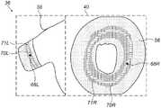
図2~図8は、図1に関連して、本発明の各実施形態により、患者18の肺静脈16のアブレーション処置の間に、医師14によって視認される表示画面36を示す。左側ディスプレイ38には、患者18の肺静脈16及び心臓46の3D画像が示されており、右側ディスプレイ40には、肺静脈16の選択部分の2D画像が示されている。以下に記載するように、左側ディスプレイ38の3D画像は、典型的には、操作可能であり、一方で、右側ディスプレイ40の2D画像は、典型的には、静止している。左側ディスプレイ38及び右側ディスプレイ40における対応する項目は、同じ番号でラベル付けされており、ここで、「L」及び「R」の文字は、それぞれ左側ディスプレイ及び右側ディスプレイを示している。表示画面36は、アブレーション処置に関連する追加的な情報、例えば、経過時間、及びアブレーションを行っている電極によって消費される電力などを表示してもよい。簡明にするため、このような追加的な情報は、図中に提示されない。 2-8, in connection with FIG. 1, show a
図2では、左側ディスプレイ38に、心臓46の3D画像50と、心臓46の肺静脈16の3D画像52が示されている。画像52の円筒状領域54は、医師14がアブレーション処置を実施する、肺静脈16の領域に対応する。処置の間、プロセッサ30は、右側ディスプレイ40において、円筒状領域54を2D環形56に投影し、ここで、画像50で近位側になっている、円筒状領域54の縁部58が環形56の内周60に投影され、画像50で遠位側になっている、縁部62が、環形56の外周64に投影されている。医師14は、肺静脈16に接触するようにプローブ20の先端部44を配置しており、その位置は、左側ディスプレイ38では、起点66Lで示されており、右側ディスプレイ40では起点66Rで示されている。起点66L及び起点66R、及び以下で述べる他の起点は、典型的には、先端部44に対応するアイコンとして画面36上に提示される。 In FIG. 2, the
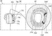
図3は、医師14がアブレーションを開始する、先端部44についての開始点を選択した後であり、かつ、アブレーションを開始する前の、表示画面36を示す。起点68L及び起点68Rは、左側ディスプレイ38及び右側ディスプレイ40におけるアブレーションの選択された開始点を、それぞれ示している。開始点が選択されると、プロセッサ30は、開始点、及び肺静脈16の既知の3D寸法に基づいて、推奨される閉じたアブレーション経路を計算する。推奨される閉じた経路が、医師14が選択した基準に基づいて計算され、この基準は、例えば、閉じた経路が肺静脈の周りの最短の経路であること、又は、閉じた経路が肺静脈の付け根から一定の距離にあること、などであってよい。推奨される閉じた経路は、領域70L及び70Rとして、左側ディスプレイ38及び右側ディスプレイ40にそれぞれ表示されている。領域70Lは、肺静脈16の周りの推奨経路に対応する画像54内の帯であり、領域70Rは、環形56内の輪である。領域70L及び70Rのそれぞれの内側には、より細い輪71L及び71Rに印が付けられ、アブレーション処置の指示において医師14を更に補助する。輪71L及び71Rは、アブレーションのための最適経路であり、領域70L及び70Rの幅は、典型的には、医師14が輪71L及び71Rから、ずらしたいと考える最大距離に基づいて、医師14によって設定される。推奨アブレーション経路は、アブレーション処置が完了したときに、心拍活動の波がブロックされるような、肺静脈16の周りの閉じた経路である。 FIG. 3 shows the
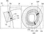
図4は、アブレーションの開始時の表示画面36を示す。左側ディスプレイ38及び右側ディスプレイ40は、図3に関して、それぞれ開始起点68L及び68Rから拡がる、第1のアブレーションについての、計算されたアブレーション損傷部画像72L及び72Rを示す。画面36においては、異なる要素の画像は、典型的には、色を変えて差異化される。本願の図面では、異なる要素の画像は、濃淡の種類の違いで差異化されている。それ故、完了したアブレーション損傷部領域は、画面36上に赤色で画像化されてもよく、図面内では網掛けで示されている。 FIG. 4 shows a
損傷部画像72L及び72Rの寸法は、先端部44により加えられている力、先端部から放出される高周波電力、経過したアブレーション時間の測定値を用いて、プロセッサ30により計算される。加えて、プロセッサ30は、領域70L及び70Rにおいて次に推奨される2つのアブレーション位置を計算し、それらを、左側ディスプレイ38における印74L及び印76Lとして、また、右側ディスプレイ40における印74R及び印76Rとして示す。次の推奨アブレーション位置は、医師に、後に続くアブレーションについて、開始位置の選択肢を2つ提供する。開示された実施形態においては、これらの位置は、アブレーションの最外縁部から一定距離にあるように計算される。一定距離は、医師14によって選択されてもよい。一実施形態においては、一定距離は、既定値が3mmであるが、この値よりも短い距離であってもよいし、又は長い距離であってもよい。 The dimensions of the damaged
次の推奨位置は、アブレーション損傷部の位置及びサイズに応じる。医師14は、肺静脈に沿って先端部44を滑らせることができ、同時に先端部を用いてアブレーションを行うことができる。代替的に、又は追加的に、医師は、アブレーションを行う間、先端部を静止させたままにしてもよい。どちらの場合も、アブレーション損傷部が拡がるにつれて、次の推奨位置が再計算され、「送り出されて(pushed out)」くる。画面36に提示される画像は、リアルタイムで生成され、2つのディスプレイ上の損傷部画像72L及び72Rのこうしたリアルタイムの提示により、医師14を補助する。医師14は、自身の判断と、画面36上の画像とに基づいて、しかしながら、画面36上のアブレーション損傷部画像が、領域70L及び70Rの縁部に達する以前に、アブレーションを終了させる。アブレーション損傷部のリアルタイムな可視化と、次のアブレーション位置の指示の両方が、アブレーション処置において連続して適用される。 The following recommended locations depend on the location and size of the ablation-damaged area. The
再び図2及び図3を参照すると、アブレーション処置の進捗と共に、左側ディスプレイ38において、医師14が、制御手段34を用いて3D画像を回転させたことがわかる。しかしながら、この回転の際、プロセッサ30により、右側ディスプレイ40の環形56が静止したままであることが確保されることから、医師14にとっては、アブレーション処置の進捗が簡単かつ迅速に観察しやすくなる。左側ディスプレイ38では、回転させるか又は他の様式で3D画像を、意のままに操作することができ、一方で、右側ディスプレイ40において、完全に静止した2D画像を同時に観察であることは、医師14にとっては大きな助けとなる。 With reference to FIGS. 2 and 3 again, it can be seen that on the
図5は、損傷部画像72L及び72Rとして表示されている第1のアブレーション損傷部の完了時、かつ、損傷部画像78L及び78Rとして示される第2のアブレーション損傷部の開始時の表示画面36を示す。図4において、それぞれ印76L及び印76Rで示された、「上側の」次の推奨位置において、第2のアブレーションが実施される。アブレーション処置が連続的であることから、プロセッサ30は、新たに次の推奨位置を計算する。それ故、プロセッサ30は、第2のアブレーション損傷部の存在を反映するために、新たな、移動した上側の次の推奨位置を計算し、印80L及び印80Rとして表示する。「下側の」次の推奨位置74L、74Rは変化しない。 FIG. 5 shows a
図6は、損傷部画像72L及び72Rとして示されている第1のアブレーション損傷部、並びに、損傷部画像78L及び78Rとして示されている第2のアブレーション損傷部が最終的なサイズに達して、互いに融合した後に、損傷部画像82L及び82Rとして示されている第3のアブレーション損傷部が形成され始めている、表示画面36を示す。この場合は、プロセッサ30は、下側の推奨位置の位置を新たな位置83L、83Rに変更し、一方で、上側の推奨位置80L、80Rの位置は変更しないままにする。 FIG. 6 shows that the first ablation-damaged part, shown as the
図7は、それぞれ損傷部画像84L及び84Rで示される連続したアブレーション損傷部が、肺静脈16の周囲の半分超に及んでいるときの、表示画面36上の、アブレーション処置の進捗を示す。アブレーション処置の進捗の迅速かつ容易な確認のために、右側ディスプレイ40上に2D画像を表示することによる利点が、左側ディスプレイ38上の3D画像と比較することで、明確に理解できる。図示されているように、2D画像の損傷部84Rでは、完全に連続した損傷部、位置83R、及びもう1つの推奨アブレーション位置85Rが表示されているが、3D画像84Lでは、損傷部の一部分と1つの推奨アブレーション位置85Lが視認できるだけである。 FIG. 7 shows the progress of the ablation procedure on the
図8には、完全なアブレーション損傷部が損傷部画像86L及び86Rとして示されている。どちらの画像も閉じた経路を表示しており、これは、図3で示した肺静脈の周りの閉じた推奨経路に対応している。しかしながら、右側ディスプレイ40の2D画像では、損傷部の連続性が直ちに視認可能かつ検証可能となっている一方で、左側ディスプレイ38の3D画像では、損傷部の連続性を検証するためには操作が必要である。 In FIG. 8, the complete ablation damaged portion is shown as the damaged
上に述べた実施形態は例として挙げたものであり、本発明は上に具体的に示し、説明したものに限定されない点が理解されるであろう。むしろ、本発明の範囲は、上記の種々の特徴の組み合わせ及び部分的組み合わせの両方、並びに前述の説明を読むことで当業者が想起するであろう、先行技術に開示されていない変形形態及び改変を含む。 It will be appreciated that the embodiments described above are given as examples and the invention is not limited to those specifically shown and described above. Rather, the scope of the invention is both combinations and partial combinations of the various features described above, as well as variants and modifications not disclosed in the prior art that would be recalled by those skilled in the art by reading the above description. including.
〔実施の態様〕
(1) 対象の体内の管腔の三次元(3D)マップを取得することと、
前記3Dマップを環形に投影することにより、前記管腔の前記3Dマップを二次元(2D)画像に変換することと、
表示画面上に前記2D画像を提示することと、を含む、データ表示方法。
(2) 前記2D画像を提示することは、静止2D画像を提示することを含む、実施態様1に記載の方法。
(3) 前記3Dマップの3D画像、及び前記静止2D画像を、前記表示画面の近接する部分に、同時に提示すること、を含む、実施態様2に記載の方法。
(4) 前記3D画像を操作している間、前記2D画像を静止したままとすることを含む、実施態様3に記載の方法。
(5) 前記3Dマップを取得することは、アブレーション処置を受ける管腔の3Dマップを取得することを含む、実施態様1に記載の方法。[Implementation mode]
(1) Obtaining a three-dimensional (3D) map of the lumen in the subject's body,
By projecting the 3D map into a ring shape, the 3D map of the lumen can be converted into a two-dimensional (2D) image.
A data display method including presenting the 2D image on a display screen.
(2) The method according to
(3) The method according to the second embodiment, comprising simultaneously presenting a 3D image of the 3D map and the still 2D image to a close portion of the display screen.
(4) The method according to the third embodiment, which comprises keeping the 2D image stationary while manipulating the 3D image.
(5) The method according to
(6) 前記アブレーション処置は、心臓の肺静脈のアブレーションを行うことを含む、実施態様5に記載の方法。
(7) 前記肺静脈における所与の開始点について、前記アブレーション処置のための経路を計算することと、前記3Dマップの3D画像、及び前記2D画像上に、前記経路の画像を表示することと、を含む、実施態様6に記載の方法。
(8) 前記3Dマップの3D画像、及び前記2D画像上に、アブレーション損傷部の算出位置及び範囲を表示することを含む、実施態様5に記載の方法。
(9) 更なるアブレーションのための推奨開始点が、前記アブレーション損傷部の前記算出位置及び前記範囲のうちの少なくとも一方に基づいて計算され、前記方法は、前記3D画像及び前記2D画像上の印として、前記推奨開始点を表示することを含む、実施態様8に記載の方法。
(10) 前記2D画像上に、連続的な閉じた損傷部の画像を提示することに応答して、前記アブレーション処置の完了を判断することを含む、実施態様6に記載の方法。(6) The method of embodiment 5, wherein the ablation procedure comprises ablating the pulmonary veins of the heart.
(7) To calculate the route for the ablation procedure for a given starting point in the pulmonary vein, and to display the image of the route on the 3D image of the 3D map and the 2D image. , The method according to embodiment 6.
(8) The method according to the fifth embodiment, which comprises displaying the calculated position and range of the ablation damaged portion on the 3D image of the 3D map and the 2D image.
(9) A recommended starting point for further ablation is calculated based on at least one of the calculated position and range of the ablation-damaged portion, the method of which is marking on the 3D image and the 2D image. The method according to embodiment 8, wherein the recommended starting point is displayed.
(10) The method of embodiment 6, comprising determining the completion of the ablation procedure in response to presenting an image of a continuous closed injury portion on the 2D image.
(11) データを表示する装置であって、
表示画面と、
プロセッサであって、
対象の体内の管腔の3Dマップを取得することと、
前記3Dマップを環形に投影することにより、前記管腔の前記3Dマップを2D画像に変換することと、
前記表示画面上に前記2D画像を提示することと、を行うように構成された、プロセッサと、を含む、装置。
(12) 前記2D画像は、静止している、実施態様11に記載の装置。
(13) 前記プロセッサは、前記3Dマップの3D画像、及び前記2D画像を、前記表示画面の近接する部分に、同時に提示するように構成されている、実施態様11に記載の装置。
(14) 前記プロセッサは、前記3D画像を操作している間、前記2D画像を静止したままとするように構成されている、実施態様13に記載の装置。
(15) 前記3Dマップは、アブレーション処置を受ける管腔の3Dマップを含む、実施態様11に記載の装置。(11) A device that displays data.
Display screen and
It ’s a processor,
Obtaining a 3D map of the lumen in the subject's body,
By projecting the 3D map in a ring shape, the 3D map of the lumen can be converted into a 2D image.
A device comprising a processor configured to present and perform the 2D image on the display screen.
(12) The device according to embodiment 11, wherein the 2D image is stationary.
(13) The apparatus according to embodiment 11, wherein the processor is configured to simultaneously present a 3D image of the 3D map and the 2D image to a nearby portion of the display screen.
(14) The apparatus according to embodiment 13, wherein the processor is configured to keep the 2D image stationary while manipulating the 3D image.
(15) The device of embodiment 11, wherein the 3D map comprises a 3D map of the lumen undergoing ablation treatment.
(16) 前記アブレーション処置は、心臓の肺静脈のアブレーションを行うことを含む、実施態様15に記載の装置。
(17) 前記プロセッサは、前記肺静脈における所与の開始点について、前記アブレーション処置のための経路を計算し、前記3Dマップの3D画像、及び前記2D画像上に、前記経路の画像を表示するように構成されている、実施態様16に記載の装置。
(18) 前記プロセッサは、前記3Dマップの3D画像、及び前記2D画像上に、アブレーション損傷部の算出位置及び範囲を表示するように構成されている、実施態様15に記載の装置。
(19) 前記プロセッサは、更なるアブレーションのための推奨開始点を、前記アブレーション損傷部の前記算出位置及び前記範囲のうちの少なくとも一方に基づいて計算し、前記3D画像及び前記2D画像上の印として、前記推奨開始点を表示するように構成されている、実施態様18に記載の装置。
(20) 前記プロセッサは、前記2D画像上に、連続的な閉じた損傷部の画像を提示することに応答して、前記アブレーション処置の完了を判断するように構成されている、実施態様16に記載の装置。(16) The device of embodiment 15, wherein the ablation procedure comprises ablating the pulmonary veins of the heart.
(17) The processor calculates a route for the ablation procedure for a given starting point in the pulmonary vein, and displays an image of the route on a 3D image of the 3D map and the 2D image. 16. The apparatus according to
(18) The apparatus according to embodiment 15, wherein the processor is configured to display a calculated position and range of an ablation damaged portion on a 3D image of the 3D map and the 2D image.
(19) The processor calculates a recommended starting point for further ablation based on at least one of the calculated position and the range of the ablation-damaged portion, and marks on the 3D image and the 2D image. The device according to
(20) In
Claims (14)
Translated fromJapanese前記3Dマップを環形に投影することにより、前記管腔の前記3Dマップを二次元(2D)画像に変換することと、
表示画面上に前記2D画像を提示することと、を含み、
前記3Dマップを取得することは、アブレーション処置を受ける管腔の3Dマップを取得することを含み、
前記アブレーション処置を受ける管腔の3Dマップは、心臓の肺静脈のアブレーション処置を受ける管腔の3Dマップであり、
前記肺静脈における所与の開始点について、前記アブレーション処置のための経路を計算することと、前記3Dマップの3D画像、及び前記2D画像上に、前記経路の画像を表示することと、を含む、データ表示装置の作動方法。Obtaining a three-dimensional (3D) map of the lumen in the subject's body,
By projecting the 3D map into a ring shape, the 3D map of the lumen can be converted into a two-dimensional (2D) image.
Including presenting the 2D image on the display screen,
Obtaining the 3D map includes obtaining a 3D map of the lumen undergoing ablation.
The 3D map of the lumen undergoing the ablation treatment is a 3D map of the lumen undergoing the ablation treatment of the pulmonary vein of the heart.
Includes calculating a route for the ablation procedure for a given starting point in the pulmonary vein and displaying an image of the route on a 3D image of the 3D map and on the 2D image. , Howto operate the data display device .
表示画面と、
プロセッサであって、
対象の体内の管腔の3Dマップを取得することと、
前記3Dマップを環形に投影することにより、前記管腔の前記3Dマップを2D画像に変換することと、
前記表示画面上に前記2D画像を提示することと、を行うように構成された、プロセッサと、を含み、
前記3Dマップは、アブレーション処置を受ける管腔の3Dマップを含み、前記アブレーション処置は、心臓の肺静脈のアブレーションを行うことを含み、
前記プロセッサは、前記肺静脈における所与の開始点について、前記アブレーション処置のための経路を計算し、前記3Dマップの3D画像、及び前記2D画像上に、前記経路の画像を表示するように構成されている、装置。A device that displays data
Display screen and
It ’s a processor,
Obtaining a 3D map of the lumen in the subject's body,
By projecting the 3D map in a ring shape, the 3D map of the lumen can be converted into a 2D image.
Includes a processor configured to present and perform the 2D image on the display screen.
The 3D map includes a 3D map of the lumen undergoing an ablation procedure, the ablation procedure comprising ablating the pulmonary veins of the heart.
The processor is configured to calculate a route for the ablation procedure for a given starting point in the pulmonary vein and display an image of the route on a 3D image of the 3D map and the 2D image. The devicethat has been .
Applications Claiming Priority (2)
| Application Number | Priority Date | Filing Date | Title |
|---|---|---|---|
| US15/388,029US10321878B2 (en) | 2016-12-22 | 2016-12-22 | Pulmonary vein display in two dimensions |
| US15/388,029 | 2016-12-22 |
Publications (2)
| Publication Number | Publication Date |
|---|---|
| JP2018102921A JP2018102921A (en) | 2018-07-05 |
| JP7046590B2true JP7046590B2 (en) | 2022-04-04 |
Family
ID=60811846
Family Applications (1)
| Application Number | Title | Priority Date | Filing Date |
|---|---|---|---|
| JP2017244771AActiveJP7046590B2 (en) | 2016-12-22 | 2017-12-21 | Two-dimensional pulmonary vein display |
Country Status (7)
| Country | Link |
|---|---|
| US (4) | US10321878B2 (en) |
| EP (2) | EP3714833B1 (en) |
| JP (1) | JP7046590B2 (en) |
| CN (1) | CN108210066B (en) |
| AU (1) | AU2017268512A1 (en) |
| CA (1) | CA2988549A1 (en) |
| IL (1) | IL255848B (en) |
Families Citing this family (15)
| Publication number | Priority date | Publication date | Assignee | Title |
|---|---|---|---|---|
| US11389232B2 (en) | 2006-06-28 | 2022-07-19 | Kardium Inc. | Apparatus and method for intra-cardiac mapping and ablation |
| US9119633B2 (en) | 2006-06-28 | 2015-09-01 | Kardium Inc. | Apparatus and method for intra-cardiac mapping and ablation |
| US8906011B2 (en) | 2007-11-16 | 2014-12-09 | Kardium Inc. | Medical device for use in bodily lumens, for example an atrium |
| US9198592B2 (en) | 2012-05-21 | 2015-12-01 | Kardium Inc. | Systems and methods for activating transducers |
| US10827977B2 (en) | 2012-05-21 | 2020-11-10 | Kardium Inc. | Systems and methods for activating transducers |
| US9017321B2 (en) | 2012-05-21 | 2015-04-28 | Kardium, Inc. | Systems and methods for activating transducers |
| US10368936B2 (en) | 2014-11-17 | 2019-08-06 | Kardium Inc. | Systems and methods for selecting, activating, or selecting and activating transducers |
| US10722184B2 (en) | 2014-11-17 | 2020-07-28 | Kardium Inc. | Systems and methods for selecting, activating, or selecting and activating transducers |
| WO2020053741A1 (en)* | 2018-09-11 | 2020-03-19 | St. Jude Medical, Cardiology Division, Inc. | Unibody intravascular catheter shaft |
| US11707320B2 (en)* | 2019-12-24 | 2023-07-25 | Biosense Webster (Israel) Ltd. | Irreversible electroporation (IRE) based on field, contact force and time |
| WO2021180826A1 (en)* | 2020-03-12 | 2021-09-16 | Koninklijke Philips N.V. | Dwelling treament monitoring for endoluminal therapy procedures |
| US11972855B2 (en) | 2021-08-12 | 2024-04-30 | Biosense Webster (Israel) Ltd. | Assessing lesions formed in an ablation procedure |
| US20230050590A1 (en)* | 2021-08-12 | 2023-02-16 | Biosense Webster (Israel) Ltd. | Presenting quality measures of tissue ablation in a blood vessel using a two-dimensional map |
| US20230190233A1 (en)* | 2021-12-20 | 2023-06-22 | Biosense Webster (Israel) Ltd. | Visualization of change in anatomical slope using 4d ultrasound catheter |
| US20240206960A1 (en)* | 2022-12-27 | 2024-06-27 | Biosense Webster (Israel) Ltd. | Caliper tool with toggling between multiple ablation modes |
Citations (7)
| Publication number | Priority date | Publication date | Assignee | Title |
|---|---|---|---|---|
| JP2005137455A (en) | 2003-11-04 | 2005-06-02 | Olympus Corp | Insertion supporting system |
| JP2007038005A (en) | 2005-08-02 | 2007-02-15 | Biosense Webster Inc | Guided procedure for treating atrial fibrillation |
| JP2011036600A (en) | 2009-08-18 | 2011-02-24 | Toshiba Corp | Image processor, image processing program and medical diagnostic system |
| JP2014507199A (en) | 2010-12-27 | 2014-03-27 | エンドーセンス エスアー | Prediction of atrial wall electrical reconnection based on contact force measured during RF ablation |
| JP2014219979A (en) | 2013-05-03 | 2014-11-20 | バイオセンス・ウエブスター・(イスラエル)・リミテッドBiosense Webster (Israel), Ltd. | Valve view map |
| WO2015164667A1 (en) | 2014-04-23 | 2015-10-29 | St. Jude Medical, Cardiology Division, Inc. | System and method for displaying cardiac mechanical activation patterns |
| JP2015226777A (en) | 2014-06-02 | 2015-12-17 | バイオセンス・ウエブスター・(イスラエル)・リミテッドBiosense Webster (Israel), Ltd. | Identification and visualization of gaps between ablation sites in the heart |
Family Cites Families (51)
| Publication number | Priority date | Publication date | Assignee | Title |
|---|---|---|---|---|
| US5718241A (en) | 1995-06-07 | 1998-02-17 | Biosense, Inc. | Apparatus and method for treating cardiac arrhythmias with no discrete target |
| CN1229346A (en) | 1996-07-05 | 1999-09-22 | 卡罗莱纳心脏研究所 | Electromagnetic Imaging and Medical Systems |
| JP3856406B2 (en)* | 1997-02-27 | 2006-12-13 | 株式会社東芝 | Image processing device |
| US8442618B2 (en)* | 1999-05-18 | 2013-05-14 | Mediguide Ltd. | Method and system for delivering a medical device to a selected position within a lumen |
| US6697538B1 (en) | 1999-07-30 | 2004-02-24 | Wisconsin Alumni Research Foundation | Apparatus for producing a flattening map of a digitized image for conformally mapping onto a surface and associated method |
| EP1393259B1 (en) | 2001-05-11 | 2018-06-13 | Koninklijke Philips N.V. | Method, system and computer program for producing a medical report |
| WO2003046811A1 (en)* | 2001-11-21 | 2003-06-05 | Viatronix Incorporated | Registration of scanning data acquired from different patient positions |
| EP1569570B1 (en) | 2002-11-27 | 2006-11-15 | Medical Device Innovations Limited | Tissue ablation apparatus |
| JP4607431B2 (en) | 2003-05-08 | 2011-01-05 | 株式会社東芝 | MRI equipment |
| DE112004001440T5 (en) | 2003-08-04 | 2007-08-09 | Siemens Medical Solutions Usa, Inc. | Unfolding a virtual organ for visualization |
| US7233329B2 (en) | 2003-11-03 | 2007-06-19 | Siemens Corporate Research, Inc. | Rendering for coronary visualization |
| US7574247B2 (en) | 2003-11-17 | 2009-08-11 | Siemens Medical Solutions Usa, Inc. | Automatic coronary isolation using a n-MIP ray casting technique |
| US7086407B2 (en)* | 2004-01-09 | 2006-08-08 | Ozone International Llc | Cleaning and sanitizing system |
| US20060025679A1 (en) | 2004-06-04 | 2006-02-02 | Viswanathan Raju R | User interface for remote control of medical devices |
| US8021300B2 (en)* | 2004-06-16 | 2011-09-20 | Siemens Medical Solutions Usa, Inc. | Three-dimensional fly-through systems and methods using ultrasound data |
| EP1761898B1 (en) | 2004-06-23 | 2019-03-27 | Koninklijke Philips N.V. | Image processing system for displaying information relating to parameters of a 3-d tubular object |
| US20060036163A1 (en) | 2004-07-19 | 2006-02-16 | Viswanathan Raju R | Method of, and apparatus for, controlling medical navigation systems |
| WO2006070669A1 (en)* | 2004-12-27 | 2006-07-06 | Olympus Corporation | Medical image processing apparatus, and medical image processing method |
| US7813535B2 (en) | 2005-04-19 | 2010-10-12 | Siemens Medical Solutions Usa, Inc. | System and method for fused PET-CT visualization for heart unfolding |
| CN101166470B (en) | 2005-04-28 | 2016-04-06 | 株式会社日立医药 | Image display device and method for displaying image |
| US7853304B2 (en) | 2005-05-13 | 2010-12-14 | Tomtec Imaging Systems Gmbh | Method and device for reconstructing two-dimensional sectional images |
| US7365745B2 (en) | 2005-09-15 | 2008-04-29 | St. Jude Medical, Atrial Fibrillation Division, Inc. | Method of rendering a surface from a solid graphical image |
| DE602006008040D1 (en) | 2005-12-19 | 2009-09-03 | Koninkl Philips Electronics Nv | PROCESS FOR FACILITATING REPRODUCTION OF IMAGES ON DEFORMABLE NETS |
| US7961924B2 (en) | 2006-08-21 | 2011-06-14 | Stereotaxis, Inc. | Method of three-dimensional device localization using single-plane imaging |
| US8135185B2 (en) | 2006-10-20 | 2012-03-13 | Stereotaxis, Inc. | Location and display of occluded portions of vessels on 3-D angiographic images |
| CN102172330B (en)* | 2007-07-10 | 2013-03-27 | 株式会社东芝 | X-ray imaging apparatus and image processing display apparatus |
| US8514218B2 (en)* | 2007-08-14 | 2013-08-20 | Siemens Aktiengesellschaft | Image-based path planning for automated virtual colonoscopy navigation |
| US20090082660A1 (en)* | 2007-09-20 | 2009-03-26 | Norbert Rahn | Clinical workflow for treatment of atrial fibrulation by ablation using 3d visualization of pulmonary vein antrum in 2d fluoroscopic images |
| US8320711B2 (en) | 2007-12-05 | 2012-11-27 | Biosense Webster, Inc. | Anatomical modeling from a 3-D image and a surface mapping |
| US8300047B2 (en) | 2008-03-10 | 2012-10-30 | Siemens Aktiengesellschaft | System and method for colon unfolding via skeletal subspace deformation |
| CN102292744B (en) | 2009-01-23 | 2015-11-25 | 皇家飞利浦电子股份有限公司 | Cardiac image process and analysis |
| CN102625670B (en)* | 2009-06-16 | 2015-07-15 | 核磁共振成像介入技术有限公司 | MRI-guided devices and MRI-guided interventional systems that can track and generate dynamic visualizations of the devices in near real time |
| US20110142306A1 (en) | 2009-12-16 | 2011-06-16 | Vivek Nair | Method and system for generating a medical image |
| US10423757B2 (en) | 2010-11-18 | 2019-09-24 | Koninklijke Philips N.V. | System and method for probabilistic ablation planning |
| KR101805619B1 (en)* | 2011-01-25 | 2017-12-07 | 삼성전자주식회사 | Apparatus and method for creating optimal 2-dimensional medical image automatically from 3-dimensional medical image |
| JP6166663B2 (en) | 2011-03-02 | 2017-07-19 | コーニンクレッカ フィリップス エヌ ヴェKoninklijke Philips N.V. | Visualization for navigation guidance |
| US20130012359A1 (en)* | 2011-05-06 | 2013-01-10 | Reed Hanoun | Sensor for Fitness Equipment |
| DE102011081987B4 (en) | 2011-09-01 | 2014-05-28 | Tomtec Imaging Systems Gmbh | Method for producing a model of a surface of a cavity wall |
| US8909502B2 (en) | 2011-12-29 | 2014-12-09 | St. Jude Medical, Atrial Fibrillation Division, Inc. | Method and system for constructing an electrophysiology map |
| CN102609623A (en)* | 2012-02-10 | 2012-07-25 | 中国人民解放军总医院 | Ablation therapy image guide device with two-dimensional image processing device |
| US9277970B2 (en) | 2012-07-19 | 2016-03-08 | Siemens Aktiengesellschaft | System and method for patient specific planning and guidance of ablative procedures for cardiac arrhythmias |
| US9895079B2 (en) | 2012-09-26 | 2018-02-20 | Biosense Webster (Israel) Ltd. | Electropotential mapping |
| JP6461916B2 (en) | 2013-04-18 | 2019-01-30 | セント・ジュード・メディカル・エイトリアル・フィブリレーション・ディヴィジョン・インコーポレーテッド | Method of operating a system for visualizing and analyzing arrhythmias utilizing a 2D planar projection and a partially developed surface mapping process |
| EP3119604A1 (en)* | 2014-03-21 | 2017-01-25 | Infiana Germany GmbH & Co. KG | Multi-layered plastic film with separation effect |
| US9835328B2 (en)* | 2014-08-02 | 2017-12-05 | Jeffrey S. Lance | Multipurpose outdoor gas fire place |
| US9536309B2 (en)* | 2014-11-27 | 2017-01-03 | Synaptive Medical (Barbados) Inc. | Method, system and apparatus for displaying surgical engagement paths |
| US20160331262A1 (en)* | 2015-05-13 | 2016-11-17 | Ep Solutions Sa | Combined Electrophysiological Mapping and Cardiac Ablation Methods, Systems, Components and Devices |
| US10779904B2 (en)* | 2015-07-19 | 2020-09-22 | 460Medical, Inc. | Systems and methods for lesion formation and assessment |
| US11842456B2 (en) | 2017-01-12 | 2023-12-12 | Navix International Limited | Flattened view for intra-lumenal navigation |
| EP3568068A1 (en) | 2017-01-12 | 2019-11-20 | Navix International Limited | Systems and methods for reconstruction of intra-body electrical readings to anatomical structure |
| EP3790453A1 (en) | 2018-05-07 | 2021-03-17 | Navix International Limited | Versatile imaging |
- 2016
- 2016-12-22USUS15/388,029patent/US10321878B2/enactiveActive
- 2017
- 2017-11-22ILIL255848Apatent/IL255848B/enactiveIP Right Grant
- 2017-11-28AUAU2017268512Apatent/AU2017268512A1/ennot_activeAbandoned
- 2017-12-11CACA2988549Apatent/CA2988549A1/ennot_activeAbandoned
- 2017-12-21EPEP20175693.9Apatent/EP3714833B1/enactiveActive
- 2017-12-21EPEP17209623.2Apatent/EP3338726B1/enactiveActive
- 2017-12-21JPJP2017244771Apatent/JP7046590B2/enactiveActive
- 2017-12-22CNCN201711415157.0Apatent/CN108210066B/enactiveActive
- 2019
- 2019-06-17USUS16/443,531patent/US11064954B2/enactiveActive
- 2021
- 2021-06-10USUS17/344,784patent/US11647966B2/enactiveActive
- 2023
- 2023-04-10USUS18/298,035patent/US12138083B2/enactiveActive
Patent Citations (7)
| Publication number | Priority date | Publication date | Assignee | Title |
|---|---|---|---|---|
| JP2005137455A (en) | 2003-11-04 | 2005-06-02 | Olympus Corp | Insertion supporting system |
| JP2007038005A (en) | 2005-08-02 | 2007-02-15 | Biosense Webster Inc | Guided procedure for treating atrial fibrillation |
| JP2011036600A (en) | 2009-08-18 | 2011-02-24 | Toshiba Corp | Image processor, image processing program and medical diagnostic system |
| JP2014507199A (en) | 2010-12-27 | 2014-03-27 | エンドーセンス エスアー | Prediction of atrial wall electrical reconnection based on contact force measured during RF ablation |
| JP2014219979A (en) | 2013-05-03 | 2014-11-20 | バイオセンス・ウエブスター・(イスラエル)・リミテッドBiosense Webster (Israel), Ltd. | Valve view map |
| WO2015164667A1 (en) | 2014-04-23 | 2015-10-29 | St. Jude Medical, Cardiology Division, Inc. | System and method for displaying cardiac mechanical activation patterns |
| JP2015226777A (en) | 2014-06-02 | 2015-12-17 | バイオセンス・ウエブスター・(イスラエル)・リミテッドBiosense Webster (Israel), Ltd. | Identification and visualization of gaps between ablation sites in the heart |
Also Published As
| Publication number | Publication date |
|---|---|
| US11064954B2 (en) | 2021-07-20 |
| US20190298274A1 (en) | 2019-10-03 |
| US20180177467A1 (en) | 2018-06-28 |
| IL255848B (en) | 2021-01-31 |
| US20210298692A1 (en) | 2021-09-30 |
| JP2018102921A (en) | 2018-07-05 |
| EP3714833B1 (en) | 2024-02-28 |
| US10321878B2 (en) | 2019-06-18 |
| EP3714833C0 (en) | 2024-02-28 |
| EP3714833A1 (en) | 2020-09-30 |
| CN108210066A (en) | 2018-06-29 |
| EP3338726A1 (en) | 2018-06-27 |
| AU2017268512A1 (en) | 2018-07-12 |
| CA2988549A1 (en) | 2018-06-22 |
| EP3338726B1 (en) | 2020-05-27 |
| US12138083B2 (en) | 2024-11-12 |
| US20230240622A1 (en) | 2023-08-03 |
| CN108210066B (en) | 2022-10-14 |
| US11647966B2 (en) | 2023-05-16 |
| IL255848A0 (en) | 2017-12-31 |
Similar Documents
| Publication | Publication Date | Title |
|---|---|---|
| JP7046590B2 (en) | Two-dimensional pulmonary vein display | |
| JP7612816B2 (en) | Velocity determination for intraluminal ultrasound imaging and related devices, systems and methods - Patents.com | |
| EP3422297B1 (en) | System and method for glass state view in real-time three-dimensional (3d) cardiac imaging | |
| JP7046591B2 (en) | Interactive anatomical mapping and quality estimation of anatomical mapping | |
| JP7179453B2 (en) | Method and apparatus for planning and controlling ablation | |
| CN110811835B (en) | Computed tomography enhanced fluoroscopy systems, devices, and methods of use thereof | |
| JP2021041171A (en) | Graphical user interface for ablation system | |
| JP2021016794A (en) | Visual guidance for positioning distal end of medical probe | |
| CN101467894B (en) | Flashlight view of anatomical structure | |
| JP7460355B2 (en) | Medical User Interface | |
| JP2020022749A (en) | Balloon positioning using magnetic resonance imaging (MRI) blood flow measurement | |
| JP7423292B2 (en) | Composite visualization of body parts | |
| US12387835B2 (en) | Assessing lesions formed in an ablation procedure | |
| CN107280737A (en) | A kind of computational methods for puncturing the anglec of rotation in traveling | |
| JP2025117691A (en) | Puncture support device, its operating method, and operating program for the puncture support device |
Legal Events
| Date | Code | Title | Description |
|---|---|---|---|
| A621 | Written request for application examination | Free format text:JAPANESE INTERMEDIATE CODE: A621 Effective date:20201023 | |
| A977 | Report on retrieval | Free format text:JAPANESE INTERMEDIATE CODE: A971007 Effective date:20210824 | |
| A131 | Notification of reasons for refusal | Free format text:JAPANESE INTERMEDIATE CODE: A131 Effective date:20210831 | |
| A521 | Request for written amendment filed | Free format text:JAPANESE INTERMEDIATE CODE: A523 Effective date:20211124 | |
| TRDD | Decision of grant or rejection written | ||
| A01 | Written decision to grant a patent or to grant a registration (utility model) | Free format text:JAPANESE INTERMEDIATE CODE: A01 Effective date:20220315 | |
| A61 | First payment of annual fees (during grant procedure) | Free format text:JAPANESE INTERMEDIATE CODE: A61 Effective date:20220323 | |
| R150 | Certificate of patent or registration of utility model | Ref document number:7046590 Country of ref document:JP Free format text:JAPANESE INTERMEDIATE CODE: R150 | |
| R250 | Receipt of annual fees | Free format text:JAPANESE INTERMEDIATE CODE: R250 |