JP7045890B2 - Pattern drawing device and pattern drawing method - Google Patents
Pattern drawing device and pattern drawing methodDownload PDFInfo
- Publication number
- JP7045890B2 JP7045890B2JP2018052209AJP2018052209AJP7045890B2JP 7045890 B2JP7045890 B2JP 7045890B2JP 2018052209 AJP2018052209 AJP 2018052209AJP 2018052209 AJP2018052209 AJP 2018052209AJP 7045890 B2JP7045890 B2JP 7045890B2
- Authority
- JP
- Japan
- Prior art keywords
- substrate
- cameras
- camera group
- arrangement direction
- camera
- Prior art date
- Legal status (The legal status is an assumption and is not a legal conclusion. Google has not performed a legal analysis and makes no representation as to the accuracy of the status listed.)
- Active
Links
- 238000000034methodMethods0.000titleclaimsdescription20
- 239000000758substrateSubstances0.000claimsdescription121
- 230000007246mechanismEffects0.000claimsdescription59
- 230000033001locomotionEffects0.000claimsdescription36
- 230000008569processEffects0.000claimsdescription11
- 230000008859changeEffects0.000claimsdescription5
- 238000012545processingMethods0.000description18
- 230000003287optical effectEffects0.000description15
- 238000003780insertionMethods0.000description6
- 230000037431insertionEffects0.000description6
- 238000010586diagramMethods0.000description5
- 238000005286illuminationMethods0.000description5
- 230000006870functionEffects0.000description4
- 238000004891communicationMethods0.000description3
- 230000001678irradiating effectEffects0.000description3
- 239000004973liquid crystal related substanceSubstances0.000description3
- XUIMIQQOPSSXEZ-UHFFFAOYSA-NSiliconChemical compound[Si]XUIMIQQOPSSXEZ-UHFFFAOYSA-N0.000description2
- 239000000919ceramicSubstances0.000description2
- 238000006243chemical reactionMethods0.000description2
- 238000005401electroluminescenceMethods0.000description2
- 239000004065semiconductorSubstances0.000description2
- 229910052710siliconInorganic materials0.000description2
- 239000010703siliconSubstances0.000description2
- 230000009471actionEffects0.000description1
- 239000000853adhesiveSubstances0.000description1
- 230000001070adhesive effectEffects0.000description1
- 230000008878couplingEffects0.000description1
- 238000010168coupling processMethods0.000description1
- 238000005859coupling reactionMethods0.000description1
- 230000026058directional locomotionEffects0.000description1
- 239000000835fiberSubstances0.000description1
- 230000004907fluxEffects0.000description1
- 239000000463materialSubstances0.000description1
- 238000005259measurementMethods0.000description1
- 238000012986modificationMethods0.000description1
- 230000004048modificationEffects0.000description1
Images


Classifications
- G—PHYSICS
- G03—PHOTOGRAPHY; CINEMATOGRAPHY; ANALOGOUS TECHNIQUES USING WAVES OTHER THAN OPTICAL WAVES; ELECTROGRAPHY; HOLOGRAPHY
- G03F—PHOTOMECHANICAL PRODUCTION OF TEXTURED OR PATTERNED SURFACES, e.g. FOR PRINTING, FOR PROCESSING OF SEMICONDUCTOR DEVICES; MATERIALS THEREFOR; ORIGINALS THEREFOR; APPARATUS SPECIALLY ADAPTED THEREFOR
- G03F1/00—Originals for photomechanical production of textured or patterned surfaces, e.g., masks, photo-masks, reticles; Mask blanks or pellicles therefor; Containers specially adapted therefor; Preparation thereof
- G03F1/20—Masks or mask blanks for imaging by charged particle beam [CPB] radiation, e.g. by electron beam; Preparation thereof
- G—PHYSICS
- G03—PHOTOGRAPHY; CINEMATOGRAPHY; ANALOGOUS TECHNIQUES USING WAVES OTHER THAN OPTICAL WAVES; ELECTROGRAPHY; HOLOGRAPHY
- G03F—PHOTOMECHANICAL PRODUCTION OF TEXTURED OR PATTERNED SURFACES, e.g. FOR PRINTING, FOR PROCESSING OF SEMICONDUCTOR DEVICES; MATERIALS THEREFOR; ORIGINALS THEREFOR; APPARATUS SPECIALLY ADAPTED THEREFOR
- G03F7/00—Photomechanical, e.g. photolithographic, production of textured or patterned surfaces, e.g. printing surfaces; Materials therefor, e.g. comprising photoresists; Apparatus specially adapted therefor
- G03F7/70—Microphotolithographic exposure; Apparatus therefor
- G03F7/70691—Handling of masks or workpieces
- G03F7/70775—Position control, e.g. interferometers or encoders for determining the stage position
- G—PHYSICS
- G03—PHOTOGRAPHY; CINEMATOGRAPHY; ANALOGOUS TECHNIQUES USING WAVES OTHER THAN OPTICAL WAVES; ELECTROGRAPHY; HOLOGRAPHY
- G03F—PHOTOMECHANICAL PRODUCTION OF TEXTURED OR PATTERNED SURFACES, e.g. FOR PRINTING, FOR PROCESSING OF SEMICONDUCTOR DEVICES; MATERIALS THEREFOR; ORIGINALS THEREFOR; APPARATUS SPECIALLY ADAPTED THEREFOR
- G03F9/00—Registration or positioning of originals, masks, frames, photographic sheets or textured or patterned surfaces, e.g. automatically
- G03F9/70—Registration or positioning of originals, masks, frames, photographic sheets or textured or patterned surfaces, e.g. automatically for microlithography
- G03F9/7003—Alignment type or strategy, e.g. leveling, global alignment
Landscapes
- Physics & Mathematics (AREA)
- General Physics & Mathematics (AREA)
- Exposure And Positioning Against Photoresist Photosensitive Materials (AREA)
- Length Measuring Devices By Optical Means (AREA)
- Container, Conveyance, Adherence, Positioning, Of Wafer (AREA)
Description
Translated fromJapanese本発明は、基板にパターンを描画する技術に関し、特に、基板の位置を特定する技術に関する。処理対象となる基板には、半導体基板、液晶表示装置および有機EL(Electroluminescence)表示装置などのFPD(Flat Panel Display)用基板、光ディスク用基板、磁気ディスク用基板、光磁気ディスク用基板、フォトマスク用基板、セラミック基板、太陽電池用基板、並びに、プリント基板などが含まれる。 The present invention relates to a technique for drawing a pattern on a substrate, and more particularly to a technique for specifying a position of the substrate. The substrates to be processed include FPD (Flat Panel Display) substrates such as semiconductor substrates, liquid crystal displays and organic EL (Electroluminescence) display devices, optical disk substrates, magnetic disk substrates, optomagnetic disk substrates, and photomasks. Boards, ceramic boards, solar cell boards, printed circuit boards, etc. are included.
基板に塗布された感光材料上に光を照射して、所定のパターンを描画するパターン描画装置が使用される場合がある。従来のパターン描画装置は、基板を水平姿勢で保持しつつ移動させるステージと、基板を移動させつつ基板の上面に光を照射する複数の光学ヘッドとを備えている。パターン描画装置では、基板を移動させつつ複数の光学ヘッドから断続的に光を照射することにより、基板の上面の所定の位置にパターンを描画する。 A pattern drawing device that draws a predetermined pattern by irradiating a photosensitive material coated on a substrate with light may be used. A conventional pattern drawing apparatus includes a stage for moving a substrate while holding it in a horizontal posture, and a plurality of optical heads for irradiating the upper surface of the substrate with light while moving the substrate. In the pattern drawing apparatus, a pattern is drawn at a predetermined position on the upper surface of the substrate by intermittently irradiating light from a plurality of optical heads while moving the substrate.
このようなパターン描画装置においては、基板の上面の正確な位置にパターンを描画するために、ステージ上に保持された基板の位置を補正するアライメント処理が行われる。アライメント処理は、例えば、基板の上面に予め形成されたアライメントマークを装置内のアライメントカメラにより撮影し、撮影されたアライメントマークの画像に基づいて基板の位置ずれが補正される。 In such a pattern drawing apparatus, in order to draw a pattern at an accurate position on the upper surface of the substrate, an alignment process for correcting the position of the substrate held on the stage is performed. In the alignment process, for example, an alignment mark formed in advance on the upper surface of the substrate is photographed by an alignment camera in the apparatus, and the misalignment of the substrate is corrected based on the image of the photographed alignment mark.
本発明に関連する先行技術としては、例えば特許文献1に記載のものがある。特許文献1には、アライメントマークにアライメントカメラで複数のアライメントマークを撮影することが記載されている。 As the prior art related to the present invention, for example, there is one described in Patent Document 1. Patent Document 1 describes that a plurality of alignment marks are photographed on the alignment marks by an alignment camera.
ところで、複数のアライメントマーク(以下、「マーク」と称する。)を複数のアライメントカメラ(以下、「カメラ」と称する。)で撮影する場合、マークの位置に合わせて、各カメラをその配列方向に移動させる。そして、基板を各カメラに対してカメラの配列方向に交差するスキャン方向へ相対的に移動させることにより、各マークを効率的に撮影することができる。 By the way, when a plurality of alignment marks (hereinafter referred to as "marks") are photographed by a plurality of alignment cameras (hereinafter referred to as "cameras"), each camera is moved in the arrangement direction according to the position of the marks. Move it. Then, by moving the substrate relative to each camera in the scanning direction intersecting the arrangement direction of the cameras, each mark can be efficiently photographed.
ところが、複数のカメラを用いる場合、各カメラを配列方向に移動させる動作軸がカメラの数分必要となるなど移動機構が複雑化する。このため、装置のコストアップ、および、制御の複雑化など、様々な問題が発生する。 However, when a plurality of cameras are used, the movement mechanism becomes complicated, for example, an operation axis for moving each camera in the arrangement direction is required for the number of cameras. Therefore, various problems such as an increase in the cost of the device and complicated control occur.
そこで、本発明は、基板に形成された複数のマークを複数のカメラで撮影するにあたって、装置のコストアップおよび制御の複雑化を軽減する技術を提供することを目的とする。 Therefore, an object of the present invention is to provide a technique for reducing the cost increase of the apparatus and the complexity of control when photographing a plurality of marks formed on a substrate with a plurality of cameras.
上記課題を解決するため、第1態様は、複数のマークが表面に形成された基板にパターンを描画するパターン描画装置であって、前記基板を保持する基板保持部と、前記基板における前記マークを撮影する複数のカメラを含む第1カメラ群と、前記第1カメラ群の前記複数のカメラを配列方向に配列された状態で連結する第1連結具と、前記第1連結具により連結された前記第1カメラ群を、前記配列方向へ一体的に移動させる配列方向移動機構と、前記第1カメラ群を、前記基板保持部に対して、前記配列方向に交差するスキャン方向に相対移動させるスキャン方向移動機構とを備え、前記基板保持部が複数の前記基板を前記配列方向に並べた状態で保持可能であり、前記第1カメラ群は、前記第1連結具によって、前記基板保持部に保持された複数の基板の各々の同一位置に形成された前記マーク各々を撮影可能な間隔で連結されている。In order to solve the above problems, the first aspect is a pattern drawing device for drawing a pattern on a substrate having a plurality of marks formed on the surface, wherein the substrate holding portion for holding the substrate and the marks on the substrate are drawn. The first camera group including a plurality of cameras for photographing, the first connecting tool for connecting the plurality of cameras of the first camera group in a state of being arranged in an array direction, and the first connecting tool connected by the first connecting tool. An arrangement direction moving mechanism that integrally moves the first camera group in the arrangement direction, and a scanning direction that moves the first camera group relative to the substrate holding portion in a scanning direction that intersects the arrangement direction. A moving mechanism is provided, and the substrate holding portion can hold a plurality of the substrates in a state of being arranged in the arrangement direction, and the first camera group is held by the substrate holding portion by the first connecting tool. Each of the marks formed at the same position on each of the plurality of substrates is connected at intervals that can be photographed .
第3態様は、複数のマークが表面に形成された基板にパターンを描画するパターン描画装置であって、前記基板を保持する基板保持部と、前記基板における前記マークを撮影する複数のカメラを含む第1カメラ群と、前記第1カメラ群の前記複数のカメラを配列方向に配列された状態で連結する第1連結具と、前記第1連結具により連結された前記第1カメラ群を、前記配列方向へ一体的に移動させる配列方向移動機構と、前記第1カメラ群を、前記基板保持部に対して、前記配列方向に交差するスキャン方向に相対移動させるスキャン方向移動機構と、前記基板における前記マークを撮影する複数のカメラを含む第2カメラ群と、前記第2カメラ群の前記複数のカメラを前記配列方向に配列された状態で連結する第2連結具と、を備え、前記配列方向移動機構は、前記第2カメラ群に対して前記第1カメラ群を前記配列方向に相対的に移動させるとともに、前記スキャン方向移動機構は、前記第1カメラ群および前記第2カメラ群を前記スキャン方向へ一体的に移動させる。A third aspect isa pattern drawing device that draws a pattern on a substrate on which a plurality of marks are formed on the surface, and includes a substrate holding portion that holds the substrate and a plurality of cameras that capture the marks on the substrate. The first camera group, the first connecting tool for connecting the plurality of cameras of the first camera group in a state of being arranged in the arrangement direction, and the first camera group connected by the first connecting tool are described. An arrangement direction moving mechanism that moves integrally in the arrangement direction, a scanning direction moving mechanism that moves the first camera group relative to the substrate holding portion in a scanning direction that intersects the arrangement direction, and the substrate. The arrangement includes a second camera group including a plurality of cameras for photographing the mark, and a second connecting tool forconnecting the plurality of cameras of the second camera group in a state of being arranged in the arrangement direction. The directional movement mechanism moves the first camera group relative to the second camera group in the arrangement direction, and the scan direction movement mechanism moves the first camera group and the second camera group to the second camera group. Move in one piece in the scanning direction.
第3態様は、第1態様または第2態様のパターン描画装置であって、前記第1連結具は、前記第1カメラ群の前記複数のカメラの間隔を変更可能にする間隔可変機構を備える。Thethird aspect is the pattern drawing apparatus of the first aspector the second aspect , and the first connecting tool includes the interval variable mechanism which makes it possible to change the interval of the plurality of cameras of the first camera group.
第4態様は、複数のマークが表面に形成された基板を処理するパターン描画方法であって、(a)基板保持部が前記基板を保持する工程と、(b) 前記工程(a)の後、第1連結具によって配列方向に配列された状態で連結された複数のカメラを含む第1カメラ群を、前記基板における前記複数のマークの位置に合わせて前記配列方向に一体的に移動させる工程と、(c) 前記工程(b)の後、前記第1カメラ群を、前記基板に対して、前記配列方向に交差するスキャン方向に相対移動させる工程とを含み、前記基板保持部が複数の前記基板を前記配列方向に並べた状態で保持可能であり、前記第1カメラ群は、前記第1連結具によって、前記基板保持部に保持された複数の基板の各々の同一位置に形成された前記マーク各々を撮影可能な間隔で連結されている。Thefourth aspect is a pattern drawing method for processing a substrate on which a plurality of marks are formed on the surface, in which (a) a step of holding the substrate by asubstrate holding portion and (b) after the step (a). , A step of integrally moving a first camera group including a plurality of cameras connected in a state of being arranged in the arrangement direction by the first connecting tool in the arrangement direction according to the positions of the plurality of marks on the substrate. And (c) after the step (b), the first camera group is relatively moved with respect to the substrate in the scanning direction intersecting the arrangement direction, andthe substrate holding portion is plurality. The substrates can be held in a state of being arranged in the arrangement direction, and the first camera group is formed by the first connector at the same position of each of the plurality of substrates held by the substrate holding portion. Each of the above marks is connected at intervals that can be photographed .
第1態様のパターン描画装置によると、第一カメラ群が第1連結具で連結されていることにより、各カメラを個別に配列方向へ移動させる場合よりも、移動機構を簡易化することができる。このため、装置のコストアップ、および、制御の複雑化を軽減することができる。 According to the pattern drawing apparatus of the first aspect, since the first camera group is connected by the first connector, the movement mechanism can be simplified as compared with the case where each camera is individually moved in the arrangement direction. .. Therefore, it is possible to reduce the cost increase of the device and the complexity of control.
しかも、スキャン方向への移動によって、各基板の同一位置に形成されたマーク各々を、第1カメラ群で撮影することができる。Moreover, by moving in the scanning direction, each mark formed at the same position on each substrate can be photographed by the first camera group.
第2態様のパターン描画装置によると、第1連結具および第2連結具によって連結された第1および第2カメラ群を、配列方向に相対的に移動させることによって、基板の配列方向に並ぶ複数のマークの位置に各カメラを移動させることができる。この状態で、第1および第2カメラ群をスキャン方向に移動させることにより、複数列のマークを撮影することができる。According to the pattern drawing apparatus of thesecond aspect, a plurality of first and second camera groups connected by the first connecting tool and the second connecting tool are arranged in the arrangement direction of the substrate by relatively moving in the arrangement direction. Each camera can be moved to the position of the mark. In this state, by moving the first and second camera groups in the scanning direction, it is possible to capture a plurality of rows of marks.
第3態様のパターン描画装置によると、間隔可変機構により第1連結具が複数のカメラの間隔を変えてこれらを連結することができる。これにより、複数のマークの配列方向の間隔に合わせて、各カメラの間隔を調整することができる。According to the pattern drawing apparatus of thethird aspect, the first connecting tool can change the distance between the plurality of cameras and connect them by the spacing variable mechanism. As a result, the spacing between the cameras can be adjusted according to the spacing in the arrangement direction of the plurality of marks.
第4態様のパターン描画方法によると、第一カメラ群が第1連結具で連結されていることにより、各カメラを個別に配列方向へ移動させる場合よりも、移動機構を簡易化することができる。このため、装置のコストアップ、および、制御の複雑化を軽減することができる。しかも、スキャン方向への移動によって、各基板の同一位置に形成されたマーク各々を、第1カメラ群で撮影することができる。
According to the pattern drawing method of thefourth aspect, since the first camera group is connected by the first connector, the movement mechanism can be simplified as compared with the case where each camera is individually moved in the arrangement direction. .. Therefore, it is possible to reduce the cost increase of the device and the complexity of control.Moreover, by moving in the scanning direction, each mark formed at the same position on each substrate can be photographed by the first camera group.
以下、添付の図面を参照しながら、本発明の実施形態について説明する。なお、この実施形態に記載されている構成要素はあくまでも例示であり、本発明の範囲をそれらのみに限定する趣旨のものではない。図面においては、理解容易のため、必要に応じて各部の寸法や数が誇張又は簡略化して図示されている場合がある。 Hereinafter, embodiments of the present invention will be described with reference to the accompanying drawings. It should be noted that the components described in this embodiment are merely examples, and the scope of the present invention is not limited to them. In the drawings, the dimensions and numbers of each part may be exaggerated or simplified as necessary for easy understanding.
<1. 第1実施形態>
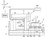
図1は、第1実施形態のパターン描画装置1を示す概略側面図である。パターン描画装置1は、レジストなどの層が形成された基板9の上面に、CADデータなどに応じて空間変調した光(描画光)を照射して、パターン(例えば、回路パターン)を露光(描画)する装置である。パターン描画装置1で処理対象とされる基板9は、例えば、プリント基板、半導体基板、液晶表示装置または有機EL(Electroluminescence)表示装置などのFPD(Flat Panel Display)用基板、光ディスク用基板、磁気ディスク用基板、光磁気ディスク用基板、フォトマスク用基板、セラミック基板、太陽電池用基板などである。以下の説明では、基板9は矩形板状に形成されているものとする。<1. First Embodiment>
FIG. 1 is a schematic side view showing the pattern drawing apparatus 1 of the first embodiment. The pattern drawing device 1 irradiates the upper surface of the
パターン描画装置1は、基台15、門型の支持フレーム16、ステージ2、ステージ駆動機構3、ステージ位置計測部4、カメラ5、描画ユニット6、および、制御部7を備える。 The pattern drawing device 1 includes a
ステージ2は、基板9を保持する保持部である。ステージ2は、基台15上に配置される。ステージ2は、具体的には、例えば、平板状の外形を有し、その上面に基板9を水平姿勢に載置して保持する。ステージ2は、複数の基板9を同時に保持することが可能である。例えば、ステージ2の上面には、複数の吸引孔(図示省略)が形成されており、この吸引孔に負圧(吸引圧)を形成することによって、ステージ2上に載置された基板9をステージ2の上面に固定保持する。なお、基板9を保持する構成は、これに限定されない。例えば、粘着シートなどを用いて基板9をステージ2上に接着させてもよい。 The
<ステージ駆動機構3>
ステージ駆動機構3は、ステージ2を基台15に対して相対的に移動させる。ステージ駆動機構3は、基台15上に配置されている。<Stage drive mechanism 3>
The stage drive mechanism 3 moves the
ステージ駆動機構3は、具体的には、ステージ2を回転方向(Z軸周りの回転方向(θ軸方向))に回転させる回転機構31と、回転機構31を介してステージ2を支持する支持プレート32と、支持プレート32を副走査方向(X軸方向)に移動させる副走査機構33とを備える。ステージ駆動機構3は、さらに、副走査機構33を介して支持プレート32を支持するベースプレート34と、ベースプレート34を主走査方向(Y軸方向)に移動させる主走査機構35とを備える。 Specifically, the stage drive mechanism 3 includes a
回転機構31は、ステージ2の上面(基板9の載置面)の中心を通り、当該載置面に垂直な回転軸Aを中心としてステージ2を回転させる。回転機構31は、例えば、上端が載置面の裏面側に固着され、鉛直軸に沿って延在する回転軸部311と、回転軸部311の下端に設けられ、回転軸部311を回転させる回転駆動部(例えば、回転モータ)312とを含む構成とすることができる。この構成においては、回転駆動部312が回転軸部311を回転させることにより、ステージ2が水平面内で回転軸Aを中心として回転することになる。 The
副走査機構33は、支持プレート32の下面に取り付けられた移動子とベースプレート34の上面に敷設された固定子とにより構成されたリニアモータ331とを有している。また、ベースプレート34には、副走査方向に延びる一対のガイド部材332が敷設されており、各ガイド部材332と支持プレート32との間には、ガイド部材332に摺動しながら当該ガイド部材332に沿って移動可能なボールベアリングが設置されている。つまり、支持プレート32は、当該ボールベアリングを介して一対のガイド部材332上に支持される。この構成においてリニアモータ331を動作させると、支持プレート32はガイド部材332に案内された状態で副走査方向に沿って滑らかに移動する。 The sub-scanning mechanism 33 has a
主走査機構35は、ベースプレート34の下面に取り付けられた移動子と基台15上に敷設された固定子とにより構成されたリニアモータ351を有している。また、基台15には、主走査方向に延びる一対のガイド部材352が敷設されており、各ガイド部材352とベースプレート34との間には例えばエアベアリングが設置されている。エアベアリングにはユーティリティ設備から常時エアが供給されており、ベースプレート34は、エアベアリングによってガイド部材352上に非接触で浮上支持される。この構成においてリニアモータ351を動作させると、ベースプレート34はガイド部材352に案内された状態で主走査方向に沿って摩擦なしで滑らかに移動する。 The
<ステージ位置計測部4>
ステージ位置計測部4は、ステージ2の位置を計測する。ステージ位置計測部4は、具体的には、例えば、ステージ2外からステージ2に向けてレーザ光を出射するとともにその反射光を受光する。ステージ位置計測部4は、当該反射光と出射光との干渉からステージ2の位置(具体的には、主走査方向に沿うY位置、および、回転方向に沿うθ位置)を計測する、干渉式のレーザ測長器を構成する。<Stage
The stage
<カメラ5>
カメラ5は、ステージ2に保持された基板9の上面を撮影する光学機器である。カメラ5は、支持フレーム16に支持される。カメラ5は、例えば、鏡筒と、フォーカシングレンズと、CCDイメージセンサと、駆動部とを備える。鏡筒は、撮影用の照明光(ただし、照明光としては、基板9上のレジストなどを感光させない波長の光が選択されている)を供給する照明ユニット500と、ファイバケーブルなどを介して接続されている。CCDイメージセンサは、エリアイメージセンサ(二次元イメージセンサ)などにより構成される。また、駆動部は、モータなどにより構成され、フォーカシングレンズを駆動してその高さ位置を変更する。駆動部が、フォーカシングレンズの高さ位置を調整することによって、オートフォーカスが行われる。<
The
このような構成を備えるカメラ5においては、照明ユニット500から出射される光が鏡筒に導入され、フォーカシングレンズを介して、ステージ2上の基板9の上面に導かれる。そして、その反射光が、CCDイメージセンサで受光される。これによって、基板9の上面に形成されたマーク91(図8参照)の撮影データが取得される。この撮影データは、制御部7に送られて、基板9のアライメント(位置合わせ)に供される。 In the
パターン描画装置1は、6つのカメラ5を備えている。6つのカメラ5は、X軸方向に並べられた状態で支持フレーム16に取り付けられている。以下の説明では、6つのカメラ5について、+X側から-X側に向けて、順に、カメラ5a,5b,5c,5d,5e,5fと称する。 The pattern drawing device 1 includes six
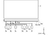
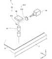
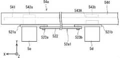
図2は、第1実施形態のカメラ5a~5fを示す概略平面図である。図3は、第1実施形態のカメラ5a,5dおよび配列方向移動機構54aを示す概略斜視図である。なお、図3は、配列方向移動機構54aを、-Y側正面から-X側に向かって斜めに見た様子を示す図である。図4は、第1実施形態のカメラ5a,5dおよび配列方向移動機構54aを示す概略平面図である。 FIG. 2 is a schematic plan view showing the
まず、図2にて概略的に示すように、2つのカメラ5a,5d(第1カメラ群)は連結具52a(第1連結具)で連結され、2つのカメラ5b,5e(第2カメラ群)は連結具52b(第2連結具)で連結され、2つのカメラ5c,5f(第3カメラ群)は連結具52c(第3連結具)で連結されている。 First, as schematically shown in FIG. 2, the two
連結具52a~52c各々は、X軸方向に延びる部材である。連結具52aは、カメラ5a,5dをX軸方向に所定の間隔をあけて連結する。同様に、連結具52b,52cは、それぞれ、カメラ5b,5e、および、カメラ5c,5fをX軸方向に所定の間隔をあけて並列させた状態で、各々を連結する。本実施形態では、X軸方向が配列方向に対応する。なお、本実施形態では、各連結具52a~52cは、それぞれ2つのカメラ5を連結させているが、3つ以上のカメラ5を連結していてもよい。 Each of the
パターン描画装置1は、配列方向移動機構54(54a,54b,54c)を備える。配列方向移動機構54aはカメラ5a,5dを、配列方向移動機構54bはカメラ5b,5eを、配列方向移動機構54cはカメラ5c,5fを、それぞれ一体的にX軸方向に移動させる。配列方向移動機構54a~54cは、上下(Z軸方向)に多段に重ねて設けられている。 The pattern drawing device 1 includes an arrangement direction moving mechanism 54 (54a, 54b, 54c). The arrangement
図3および図4にて詳細に示すように、配列方向移動機構54aは、ボールネジ541と、回転駆動部542、スライド部543a,543b、および、ガイド部544とを備えている。 As shown in detail in FIGS. 3 and 4, the arrangement
ボールネジ541、ガイド部544は、X軸方向に延びている。ボールネジ541は、ガイド部544の内部に収容されている。回転駆動部542は、ボールネジ541をX軸まわりに回転させる。 The
ガイド部544は、その内部にスライド部543a,543bをX軸方向に移動可能に保持している。詳細には、ガイド部544は、スライド部543a,543bを上下から摺接移動可能に保持している。ガイド部544は、スライド部543a,543bがX軸方向のみに移動するように移動方向を規制する。 The
ボールネジ541は、スライド部543a,543bをX軸方向に貫通している。スライド部543aは、ボールネジ541に螺合するネジ穴を有する。また、スライド部543bは、ボールネジ541の外径(ネジ山の径)よりも大きい内径の挿通孔543Hを有している。スライド部543bはボールネジ541には非接触の状態で、ガイド部544に保持されている。 The
ガイド部544の-Y側には、連結具52aが配されている。そして、連結具52aは、ガイド部544の内部に保持されたスライド部543a,543bに連結されている。図3に示すように、連結具52aの-Y側の表面に、カメラ5a,5dが取り付けられている。スライド部543aはカメラ5aとY軸方向に重なる位置に設けられており、スライド部543bはカメラ5dとY軸方向に重なる位置に設けられている。 A
回転駆動部542がボールネジ541を正回転または逆回転させることにより、スライド部543aが+X方向または-X方向に移動する。このスライド部543aの移動に伴い、連結具52aが+X方向または-X方向に移動する。このとき、連結具52aに連結されたスライド部543bがガイド部544に案内されて、+X方向または-X方向へ移動する。また、連結具52aの+X方向または-X方向への移動に伴い、カメラ5a,5dが一体的に+X方向または-X方向に一体的に移動する。 When the
配列方向移動機構54b,54cについても、配列方向移動機構54aと同様の構成を有する。配列方向移動機構54a~54cは、それぞれ、連結具52a~52cを互いに接触させないようにX軸方向に移動させる。 The arrangement
図1に戻って、描画ユニット6は、描画光を形成する光学装置である。パターン描画装置1は、描画ユニット6を複数(例えば、5つ)備える。もっとも、描画ユニット6の搭載数は、複数であることは必須ではなく、1つであってもよい。 Returning to FIG. 1, the
図5は、第1実施形態の描画ヘッド60を示す概略斜視図である。描画ユニット6は、描画ヘッド60と、光源装置61と、空間光変調デバイス62と、投影光学系63とを備える。光源装置61、空間光変調デバイス62および投影光学系63は、支持フレーム16(図1参照)に支持される。具体的には、例えば、光源装置61は、支持フレーム16の天板上に載置される収容ボックスに収容される。また、空間光変調デバイス62および投影光学系63は、支持フレーム16の+Y側に固定された収容ボックスに収容される。 FIG. 5 is a schematic perspective view showing the drawing
光源装置61は、描画ヘッド60に向けて光を出射する。光源装置61は、具体的には、例えば、レーザ光を出射するレーザ発振器などを備える。光源装置61は、レーザ発振器から出射された光(スポットビーム)を、強度分布が均一な線状の光(すなわち、光束断面が帯状の光であるラインビーム)とする照明光学系613を備える。照明光学系613は、光源装置61から出力された光を空間光変調デバイス62へと導く。照明光学系613は、例えば、レンズ614とミラー615とを備える。 The
空間光変調デバイス62は、例えば、DMD(デジタル・マイクロミラー・デバイス)を含む。DMDは、それぞれの向きが個別に変更可能な微小鏡面群を備えている。多数の微小鏡面は、シリコン基板上に形成されており、かつ、多数の微小鏡面が2次元に配列されている(すなわち、互いに垂直な2方向に整列されたアレイ状に配列されている)。 Spatial
空間光変調デバイス62では、各微小鏡面に対応するメモリセルに書き込まれたデータに従って、各微小鏡面が静電作用によりシリコン基板の表面に対して所定の角度だけ傾く。そして、所定のON状態に対応する姿勢にある微小鏡面からの反射光のみにより形成される光(すなわち、空間変調された光)が、投影光学系63へと導かれる。なお、空間光変調デバイス62として、反射型及び回折格子型の空間光変調器であるGLV(Grating Light Valve)も採用され得る。 In the spatial
空間光変調デバイス62にて空間変調された光は、投影光学系63により、ステージ2上の基板9(図1参照)へと導かれる。投影光学系63からの光は、空間光変調デバイス62の微小鏡面群に対して光学的に共役な基板9上の照射領域へと照射される。 The light spatially modulated by the spatial
図6は、第1実施形態の制御部7の構成を示すブロック図である。制御部7は、パターン描画装置1が備える各部と電気的に接続されており、各種の演算処理を実行しつつパターン描画装置1の各部の動作を制御する。 FIG. 6 is a block diagram showing the configuration of the
制御部7は、CPU71、ROM72、RAM73、記憶装置74等がバスライン75を介して相互接続された一般的なコンピュータとして構成される。ROM72は、基本プログラムなどを格納している。RAM73は、CPU71が所定の処理を行う際の作業領域として供される。記憶装置74は、フラッシュメモリ、あるいは、ハードディスク装置等の不揮発性の記憶装置によって構成されている。記憶装置74には、プログラムPGがインストールされている。当該プログラムPGに既述された手順に従って、主制御部としてのCPU71が演算処理を行うことにより、制御部7は、基板データ処理部711、配列方向移動制御部713、スキャン方向移動制御部715、画像処理部717として機能する。なお、各機能は、専用の論理回路で構成されたハードウェアによって実現されてもよい。 The
基板データ処理部711は、ステージ2に載置される基板9に関する基板データを取り込む。基板データは、基板9の大きさ、基板9におけるマーク91が形成されている位置情報などを含む。基板データは、例えば、記憶装置74などに保存されている。基板データ処理部711が取り込んだ基板データから、基板9のステージ2上における載置位置などが特定される。また、基板データから、ステージ2に載置された基板9におけるマーク91のパターン描画装置1における位置(X軸座標およびY軸座標)が特定可能となる。 The board
配列方向移動制御部713は、配列方向移動機構54a~54cを制御することにより、複数のカメラ5a~5fの配列方向(X軸方向)の移動を制御する。ここでは、配列方向移動制御部713は、基板データ処理部711が取り込んだ基板データから特定される複数のマーク91のX軸方向位置に合わせて、カメラ5a~5f各々を配列方向であるX軸方向に移動させる。 The arrangement direction
スキャン方向移動制御部715は、主走査機構35(スキャン方向移動機構)を制御することにより、ステージ2をY軸方向に移動させる。ステージ2がY軸方向に移動することにより、基板9をY軸方向に移動させることができる。これにより、複数のカメラ5または複数の描画ヘッド60に対して、基板9をY軸方向(スキャン方向)に相対的に移動させることができる。 The scan direction
画像処理部717は、各カメラ5a~5fが撮影することによって得られた画像データを、画像処理することによって、マーク91の位置を特定する。 The
また、制御部7は、バスライン75に接続された、入力部76、表示部77および通信部78を備える。入力部76は、例えば、キーボードおよびマウスによって構成される入力デバイスであり、オペレータからの各種の操作(コマンドや各種データの入力といった操作)を受け付ける。なお、入力部76は、各種スイッチ、タッチパネルなどにより構成されてもよい。表示部77は、液晶表示装置、ランプなどにより構成される表示装置であり、CPU71による制御の下、各種の情報を表示する。通信部78は、ネットワークを介して外部装置との間でコマンドやデータなどの送受信を行うデータ通信機能を有する。 Further, the
図7は、第1実施形態のマーク位置取得処理の流れを示す図である。まず、外部からパターン描画装置1に搬入された基板9が、ステージ2上に搬入されるとともに、当該基板9がステージ2上の一定位置に保持される(ステップS10)。なお、ステージ2に保持される基板9の数は、1つであってもよいし、複数であってもよい。 FIG. 7 is a diagram showing the flow of the mark position acquisition process of the first embodiment. First, the
基板9の搬入が完了すると、マーク位置取得処理が開始される。具体的には、制御部7が、基板データを取り込む(ステップS11)。詳細には、基板データ処理部711は、ステージ2に保持された基板9におけるマーク91の位置情報、および、基板9の大きさなどが記録された基板データを、記憶装置74から読み取りする。複数種類の基板に関する基板データが記憶装置74に保存されてる場合、基板データ処理部711は、処理対象の基板の種類や処理内容等が記録された処理レシピを参照する、あるいは、オペレータからの指定を受け付けることによって、ステージ2に保持された基板9を特定するとよい。 When the loading of the
続いて、基板データ処理部711が、基板データに基づき、基板9上の座標系を、パターン描画装置1におけるX軸・Y軸座標系に変換する(ステップS12)。詳細には、基板データ処理部711が、基板データから得られる基板9の大きさなどから、ステージ2上にて保持される位置(被保持位置)を特定する。そして、基板データ処理部711は、この被保持位置から、基板9上の座標系を、パターン描画装置1におけるX軸・Y軸座標系に変換する座標変換式が求められる。 Subsequently, the board
続いて、基板データ処理部711が、各カメラ5a~5fの移動開始位置を算出する(ステップS13)。詳細には、マーク91の位置情報が記録された基板データと、ステップS12にて求められた座標変換式に基づき、基板9に形成された複数のマーク91の各X軸座標が特定される。この各X軸座標が、各カメラ5a~5fの移動開始位置とされる。 Subsequently, the board
ステップS13の後、配列方向移動制御部713が、マーク91のX軸方向(配列方向)の位置に合わせて、各カメラ5a~5fをX軸方向に移動させる(ステップS14)。本実施形態では、カメラ5a,5d、カメラ5b,5e、および、カメラ5c,5fは、連結具52a~52cで連結されているため、一体的にX軸方向に移動する。ステップS14において、配列方向移動制御部713は、各カメラ5a~5fを、複数のマーク91のX軸方向の位置に対応するように移動させる。 After step S13, the arrangement direction
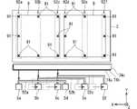
図8は、各カメラ5a~5fを配列方向に移動させる様子を示す概略平面図である。図8に示す例では、ステージ2上に、同一サイズの2つの基板9がX軸方向に所定の間隔をあけて並列するように保持されている。各基板9は、矩形状である。そして、各基板9には、計8つのマーク91がそれぞれ形成されている。具体的に、マーク91は、各基板9の四隅各々と、各基板9の四側辺の各中央に形成されている。すなわち、ステージ2に保持された各基板9には、Y軸方向に並ぶマーク91の列が、X軸方向に3列ずつ、計6列並んでいる。 FIG. 8 is a schematic plan view showing how the
ここで、+X側基板9の3つのマーク91の列について、+X側から-X側に向けて、順に、マーク列92a,92b,92cと称する。また、-X側基板9の3つのマーク91の列について、+X側から-X側に向けて、順に、マーク列92d,92e,92fと称する。マーク列92a,92c,92d,92f各々にはY軸方向に等間隔で並ぶ3つのマーク91が含まれ、マーク列92b,92eにはY軸方向に等間隔で並ぶ2つのマーク91が含まれる。 Here, the rows of the three
連結具52aで連結されたカメラ5a,5dの間隔は、マーク列92a,92dの間隔に一致する。このため、図8に示すように、配列方向移動制御部713が、カメラ5aのX軸方向位置をマーク列92aに合わせると、カメラ5dのX軸方向位置がマーク列92dに合わせられる。 The distance between the
同様に、連結具52bで連結されたカメラ5b,5eの間隔は、マーク列92b,92eの間隔に一致する。このため、図8に示すように配列方向移動制御部713がカメラ5bのX軸方向位置をマーク列92bに合わせると、カメラ5eのX軸方向位置が-X側基板9のマーク列92eに合わせられる。 Similarly, the distance between the
さらに、連結具52cで連結されたカメラ5c,5fの間隔は、マーク列92c,92fの間隔に一致する。このため、図8に示すように配列方向移動制御部713がカメラ5cのX軸方向位置をマーク列92cに合わせると、カメラ5fのX軸方向位置がマーク列92fに合わせられる。 Further, the distance between the
図7に戻って、配列方向移動制御部713がカメラ5a~5f各々を撮影開始位置移動させると、スキャン方向移動制御部715がステージ2をスキャン方向であるY軸方向に移動させる(ステップS15)。これにより、カメラ5a~5f各々は、下方を通過する各マーク91を撮影する。 Returning to FIG. 7, when the array direction
ステップS15により、カメラ5a~5fの基板9に対するY軸方向への1回の相対的移動が完了すると、制御部7は、基板データに基づき、全てのマーク91が撮影されたか否かを判定する(ステップS16)。未撮影のマーク91がある場合(ステップS16においてNo)、制御部7は、ステップS13~ステップS15を再度実行する。このように、全ての撮影すべきマーク91の撮影が完了するまで、ステップS13~ステップS16が繰り返し実行される。全てのマーク91の撮影が完了した場合(ステップS16においてYes)、制御部7は、マーク取得処理を終了する。 When one relative movement of the
図8に示す例では、上述したように、ステップS14にて、カメラ5a~5fがマーク列92a~92fのそれぞれに対応するX軸方向の位置に配置される。この状態から、ステップS15にてカメラ5a~5fに対して基板9を+Y方向(スキャン方向)に相対的に移動させることにより、各マーク列92a~92fを構成するマーク91を撮影することができる。また、この例では、+Y方向への1回のスキャンで、2つの基板9に形成された全てのマーク91について撮影することが可能となっている。 In the example shown in FIG. 8, as described above, in step S14, the
以上のように、パターン描画装置1では、複数のカメラ5a~5fがX軸方向に配列されている。このため、カメラ5a~5fの1回のスキャン方向(Y軸方向)への相対的な移動によって、X軸方向に複数列(図8に示す例では、マーク列92a~92f)で配された複数のマーク91を撮影することができる。したがって、マーク91の撮影時間を短縮できる。 As described above, in the pattern drawing apparatus 1, a plurality of
また、X軸方向に並列された複数のカメラ5(例えばカメラ5a,5d)が連結されて一体的にX軸方向に移動することができる。このため、各々のカメラ5について独立にX軸方向へ移動させる機構を設ける場合よりも移動機構を簡素化することができる。したがって、複数のカメラ5を設けることによる、パターン描画装置1のコストアップを軽減することができる。また、制御機構を簡素化することができるため、制御の複雑化を軽減することもできる。 Further, a plurality of cameras 5 (for example,
<2. 第2実施形態>
次に、第2実施形態について説明する。なお、以降の説明において、既に説明した要素と同様の機能を有する要素については、同じ符号又はアルファベット文字を追加した符号を付して、詳細な説明を省略する場合がある。<2. 2nd Embodiment>
Next, the second embodiment will be described. In the following description, elements having the same functions as the elements already described may be given the same code or a code to which alphabetic characters are added, and detailed description may be omitted.
図9は、第2実施形態の連結具52a1を示す概略平面図である。連結具52a~52cは、当該連結具52a~52cをX軸方向において長尺化または短尺化可能にする構成を備えていてもよい。 FIG. 9 is a schematic plan view showing the connector 52a1 of the second embodiment. The
図9に示すように、第2実施形態の連結具52a1は、連結具52aと同様に、カメラ5a,5dを連結する。連結具52a1は、一対の固定部材521a,521bと、連結部材522と、固定具523a,523bを備えている。 As shown in FIG. 9, the connecting tool 52a1 of the second embodiment connects the
固定部材521aは、一方側(-Y側)がカメラ5aに固定され、他方側(+Y側)がスライド部543aに固定されている。また、固定部材521bは、一方側がカメラ5dに固定され、他方側がスライド部543bに固定されている。 One side (−Y side) of the fixing
連結部材522は、X軸方向に延びる長尺板状に形成された部材である。連結部材522の両側の端部は、それぞれ固定具523a,523bによって固定部材521a,521bに連結されている。固定具523a,523bは、連結部材522を、固定部材521a,521bに対して連結解除可能に連結する部材である。固定具523a,523bは、例えば、ボルトなどの締結手段である。 The connecting
連結具52a1では、連結部材522を着脱交換することが可能である。このため、固定部材521a,521b間を、異なる長さの連結部材522で連結することにより、カメラ5a,5d間のX軸方向の間隔を変更することができる。これにより、複数のマーク91のX軸方向の間隔に対応して、カメラ5a,5d間の間隔を変更することができる。 In the connecting tool 52a1, the connecting
この連結具52a1において、固定部材521a,521b、連結部材522、および、固定具523a,523bは、2つのカメラ5a,5dの間隔を変更可能にする間隔可変機構の一例である。なお、間隔可変機構は、このような構成に限定されるものではない。 In the connecting tool 52a1, the fixing
例えば、連結具52a1において、例えば、固定具523aがボルトである場合、連結部材522の+X側端部(または、固定部材521a)に、X軸方向に並ぶ複数のボルト挿通孔を設けるとよい。この場合、固定具523aを通すボルト挿通孔を変更することにより、固定部材521aに連結される連結部材522の連結位置を変更することができる。したがって、連結具52a1が、長尺化または短尺化することが可能となり、カメラ5a,5dの間隔を可変としつつ、これらを連結することができる。なお、連結部材522(または固定部材521a)において、複数のボルト挿通孔を設ける代わりに、X軸方向に延びる長尺状のボルト挿通孔を設けてもよい。 For example, in the connecting tool 52a1, for example, when the
この発明は詳細に説明されたが、上記の説明は、すべての局面において、例示であって、この発明がそれに限定されるものではない。例示されていない無数の変形例が、この発明の範囲から外れることなく想定され得るものと解される。上記各実施形態及び各変形例で説明した各構成は、相互に矛盾しない限り適宜組み合わせたり、省略したりすることができる。 Although the invention has been described in detail, the above description is exemplary in all aspects and the invention is not limited thereto. It is understood that innumerable variations not illustrated can be assumed without departing from the scope of the present invention. Each configuration described in each of the above-described embodiments and modifications can be appropriately combined or omitted as long as they do not conflict with each other.
1 パターン描画装置
2 ステージ
3 ステージ駆動機構
35 主走査機構(スキャン方向移動機構)
5a,5d カメラ(第1カメラ群)
5b,5e カメラ(第2カメラ群)
5c,5f カメラ(第3カメラ群)
52a,52a1 連結具(第1連結具)
52b 連結具(第2連結具)
52c 連結具
54a~54c 配列方向移動機構
541 ボールネジ
542 回転駆動部
543H 挿通孔
543a,543b スライド部
544 ガイド部
6 描画ユニット
60 描画ヘッド
7 制御部
711 基板データ処理部
713 配列方向移動制御部
715 スキャン方向移動制御部
9 基板
91 マーク
92a~92f マーク列1
5a, 5d camera (1st camera group)
5b, 5e camera (second camera group)
5c, 5f camera (3rd camera group)
52a, 52a1 connector (first connector)
52b Coupling tool (second connecting tool)
Claims (4)
Translated fromJapanese前記基板を保持する基板保持部と、
前記基板における前記マークを撮影する複数のカメラを含む第1カメラ群と、
前記第1カメラ群の前記複数のカメラを配列方向に配列された状態で連結する第1連結具と、
前記第1連結具により連結された前記第1カメラ群を、前記配列方向へ一体的に移動させる配列方向移動機構と、
前記第1カメラ群を、前記基板保持部に対して、前記配列方向に交差するスキャン方向に相対移動させるスキャン方向移動機構と、
を備え、
前記基板保持部が複数の前記基板を前記配列方向に並べた状態で保持可能であり、
前記第1カメラ群は、前記第1連結具によって、前記基板保持部に保持された複数の基板の各々の同一位置に形成された前記マーク各々を撮影可能な間隔で連結されている、パターン描画装置。A pattern drawing device that draws a pattern on a substrate with multiple marks formed on the surface.
A substrate holding portion that holds the substrate and
A first camera group including a plurality of cameras that capture the mark on the substrate, and
A first connecting tool for connecting the plurality of cameras of the first camera group in a state of being arranged in the arrangement direction,
An array direction movement mechanism that integrally moves the first camera group connected by the first connector in the array direction,
A scanning direction moving mechanism that moves the first camera group relative to the substrate holding portion in the scanning direction intersecting the arrangement direction.
Equippedwith
The substrate holding portion can hold a plurality of the substrates in a state of being arranged in the arrangement direction.
In the first camera group, the marks formed at the same position of each of the plurality of boards held by the board holding portion are connected by the first connecting tool at intervals that can be photographed. Device.
前記基板を保持する基板保持部と、
前記基板における前記マークを撮影する複数のカメラを含む第1カメラ群と、
前記第1カメラ群の前記複数のカメラを配列方向に配列された状態で連結する第1連結具と、
前記第1連結具により連結された前記第1カメラ群を、前記配列方向へ一体的に移動させる配列方向移動機構と、
前記第1カメラ群を、前記基板保持部に対して、前記配列方向に交差するスキャン方向に相対移動させるスキャン方向移動機構と、
前記基板における前記マークを撮影する複数のカメラを含む第2カメラ群と、
前記第2カメラ群の前記複数のカメラを前記配列方向に配列された状態で連結する第2連結具と、
を備え、
前記配列方向移動機構は、前記第2カメラ群に対して前記第1カメラ群を前記配列方向に相対的に移動させるとともに、
前記スキャン方向移動機構は、前記第1カメラ群および前記第2カメラ群を前記スキャン方向へ一体的に移動させる、パターン描画装置。A pattern drawing device that draws a pattern on a substrate with multiple marks formed on the surface.
A substrate holding portion that holds the substrate and
A first camera group including a plurality of cameras that capture the mark on the substrate, and
A first connecting tool for connecting the plurality of cameras of the first camera group in a state of being arranged in the arrangement direction,
An array direction movement mechanism that integrally moves the first camera group connected by the first connector in the array direction,
A scanning direction moving mechanism that moves the first camera group relative to the substrate holding portion in the scanning direction intersecting the arrangement direction.
A second camera group including a plurality of cameras that capture the mark on the substrate, and a second camera group.
A second connecting tool for connecting the plurality of cameras of the second camera group in a state of being arranged in the arrangement direction,
Equipped with
The arrangement direction moving mechanism moves the first camera group relative to the second camera group in the arrangement direction, and at the same time,
The scanning direction moving mechanism is a pattern drawing device that integrally moves the first camera group and the second camera group in the scanning direction.
前記第1連結具は、前記第1カメラ群の前記複数のカメラの間隔を変更可能にする間隔可変機構を備える、パターン描画装置。The pattern drawing apparatus according toclaim 1 or 2 .
The first connector is a pattern drawing device including a spacing variable mechanism that makes it possible to change the spacing between the plurality of cameras in the first camera group.
(a)基板保持部が前記基板を保持する工程と、
(b) 前記工程(a)の後、第1連結具によって配列方向に配列された状態で連結された複数のカメラを含む第1カメラ群を、前記基板における前記複数のマークの位置に合わせて前記配列方向に一体的に移動させる工程と、
(c) 前記工程(b)の後、前記第1カメラ群を、前記基板に対して、前記配列方向に交差するスキャン方向に相対移動させる工程と、
を含み、
前記基板保持部が複数の前記基板を前記配列方向に並べた状態で保持可能であり、
前記第1カメラ群は、前記第1連結具によって、前記基板保持部に保持された複数の基板の各々の同一位置に形成された前記マーク各々を撮影可能な間隔で連結されている、パターン描画方法。It is a pattern drawing method that processes a substrate with multiple marks formed on the surface.
(a) The process in which thesubstrate holding portion holds the substrate,
(b) After the step (a), the first camera group including the plurality of cameras connected in a state of being arranged in the arrangement direction by the first connector is aligned with the positions of the plurality of marks on the substrate. The process of moving integrally in the arrangement direction and
(c) After the step (b), the step of moving the first camera group relative to the substrate in the scanning direction intersecting the arrangement direction, and
Including
The substrate holding portion can hold a plurality of the substrates in a state of being arranged in the arrangement direction.
In the first camera group, the marks formed at the same position of each of the plurality of boards held by the board holding portion are connected by the first connecting tool at intervals that can be photographed. Method.
Priority Applications (4)
| Application Number | Priority Date | Filing Date | Title |
|---|---|---|---|
| JP2018052209AJP7045890B2 (en) | 2018-03-20 | 2018-03-20 | Pattern drawing device and pattern drawing method |
| TW107146798ATWI700550B (en) | 2018-03-20 | 2018-12-24 | Pattern drawing apparatus and pattern drawing method |
| CN201910040947.8ACN110308626B (en) | 2018-03-20 | 2019-01-16 | Pattern drawing device and pattern drawing method |
| KR1020190015593AKR102212541B1 (en) | 2018-03-20 | 2019-02-11 | Pattern drawing apparatus and pattern drawing method |
Applications Claiming Priority (1)
| Application Number | Priority Date | Filing Date | Title |
|---|---|---|---|
| JP2018052209AJP7045890B2 (en) | 2018-03-20 | 2018-03-20 | Pattern drawing device and pattern drawing method |
Publications (2)
| Publication Number | Publication Date |
|---|---|
| JP2019164264A JP2019164264A (en) | 2019-09-26 |
| JP7045890B2true JP7045890B2 (en) | 2022-04-01 |
Family
ID=68066091
Family Applications (1)
| Application Number | Title | Priority Date | Filing Date |
|---|---|---|---|
| JP2018052209AActiveJP7045890B2 (en) | 2018-03-20 | 2018-03-20 | Pattern drawing device and pattern drawing method |
Country Status (4)
| Country | Link |
|---|---|
| JP (1) | JP7045890B2 (en) |
| KR (1) | KR102212541B1 (en) |
| CN (1) | CN110308626B (en) |
| TW (1) | TWI700550B (en) |
Families Citing this family (2)
| Publication number | Priority date | Publication date | Assignee | Title |
|---|---|---|---|---|
| JP7386742B2 (en)* | 2020-03-24 | 2023-11-27 | 株式会社Screenホールディングス | exposure equipment |
| JP7458950B2 (en)* | 2020-09-23 | 2024-04-01 | 株式会社Screenホールディングス | Drawing System |
Citations (9)
| Publication number | Priority date | Publication date | Assignee | Title |
|---|---|---|---|---|
| JP2000068192A (en) | 1998-08-18 | 2000-03-03 | Nikon Corp | Exposure apparatus, exposure method and position detection method |
| JP2006128693A (en) | 2004-10-28 | 2006-05-18 | Asml Netherlands Bv | Apparatus and method for optically evaluating position |
| US20060170934A1 (en) | 2005-01-28 | 2006-08-03 | Picciotto Carl E | Sensing a dimensional change in a surface |
| JP2006267191A (en) | 2005-03-22 | 2006-10-05 | Pentax Industrial Instruments Co Ltd | Exposure device |
| JP2006308996A (en) | 2005-04-28 | 2006-11-09 | Fuji Photo Film Co Ltd | Exposure device |
| JP2008203556A (en) | 2007-02-20 | 2008-09-04 | Fujifilm Corp | Digital exposure equipment |
| JP2008306109A (en) | 2007-06-11 | 2008-12-18 | Nsk Ltd | Substrate transport mechanism for exposure equipment |
| JP2014006433A (en) | 2012-06-26 | 2014-01-16 | Dainippon Screen Mfg Co Ltd | Pattern drawing device |
| JP2018173468A (en) | 2017-03-31 | 2018-11-08 | ウシオ電機株式会社 | Exposure equipment and exposure method |
Family Cites Families (11)
| Publication number | Priority date | Publication date | Assignee | Title |
|---|---|---|---|---|
| JP3537202B2 (en)* | 1994-12-19 | 2004-06-14 | オリンパス株式会社 | Multi-head microscope device |
| JP3758832B2 (en)* | 1997-09-17 | 2006-03-22 | ペンタックス株式会社 | Positioning mark illumination device |
| US6701197B2 (en) | 2000-11-08 | 2004-03-02 | Orbotech Ltd. | System and method for side to side registration in a printed circuit imager |
| TWI264532B (en)* | 2001-11-05 | 2006-10-21 | Olympus Corp | Substrate inspection device |
| JP2006235204A (en)* | 2005-02-24 | 2006-09-07 | Fuji Photo Film Co Ltd | Correction method of drawing apparatus |
| JP4485381B2 (en)* | 2005-02-25 | 2010-06-23 | 富士フイルム株式会社 | Image forming apparatus and image forming method |
| TW200702940A (en)* | 2005-04-28 | 2007-01-16 | Fuji Photo Film Co Ltd | Exposure apparatus |
| JP4606990B2 (en)* | 2005-10-07 | 2011-01-05 | 富士フイルム株式会社 | Digital exposure equipment |
| JP2009192693A (en)* | 2008-02-13 | 2009-08-27 | Dainippon Screen Mfg Co Ltd | Pattern drawing device |
| CN203658731U (en)* | 2013-12-27 | 2014-06-18 | 东莞市华恒工业自动化集成有限公司 | CCD (charge coupled device) visual aligning device for film aligning machine |
| CN204347441U (en)* | 2015-01-13 | 2015-05-20 | 苏州微影光电科技有限公司 | Write-through lithographic equipment |
- 2018
- 2018-03-20JPJP2018052209Apatent/JP7045890B2/enactiveActive
- 2018-12-24TWTW107146798Apatent/TWI700550B/enactive
- 2019
- 2019-01-16CNCN201910040947.8Apatent/CN110308626B/enactiveActive
- 2019-02-11KRKR1020190015593Apatent/KR102212541B1/enactiveActive
Patent Citations (9)
| Publication number | Priority date | Publication date | Assignee | Title |
|---|---|---|---|---|
| JP2000068192A (en) | 1998-08-18 | 2000-03-03 | Nikon Corp | Exposure apparatus, exposure method and position detection method |
| JP2006128693A (en) | 2004-10-28 | 2006-05-18 | Asml Netherlands Bv | Apparatus and method for optically evaluating position |
| US20060170934A1 (en) | 2005-01-28 | 2006-08-03 | Picciotto Carl E | Sensing a dimensional change in a surface |
| JP2006267191A (en) | 2005-03-22 | 2006-10-05 | Pentax Industrial Instruments Co Ltd | Exposure device |
| JP2006308996A (en) | 2005-04-28 | 2006-11-09 | Fuji Photo Film Co Ltd | Exposure device |
| JP2008203556A (en) | 2007-02-20 | 2008-09-04 | Fujifilm Corp | Digital exposure equipment |
| JP2008306109A (en) | 2007-06-11 | 2008-12-18 | Nsk Ltd | Substrate transport mechanism for exposure equipment |
| JP2014006433A (en) | 2012-06-26 | 2014-01-16 | Dainippon Screen Mfg Co Ltd | Pattern drawing device |
| JP2018173468A (en) | 2017-03-31 | 2018-11-08 | ウシオ電機株式会社 | Exposure equipment and exposure method |
Also Published As
| Publication number | Publication date |
|---|---|
| CN110308626B (en) | 2021-12-21 |
| JP2019164264A (en) | 2019-09-26 |
| KR102212541B1 (en) | 2021-02-04 |
| KR20190110429A (en) | 2019-09-30 |
| TW201940966A (en) | 2019-10-16 |
| CN110308626A (en) | 2019-10-08 |
| TWI700550B (en) | 2020-08-01 |
Similar Documents
| Publication | Publication Date | Title |
|---|---|---|
| US20080112609A1 (en) | Position detecting method and device, patterning device, and subject to be detected | |
| KR102333949B1 (en) | Lithography apparatus | |
| JP7045890B2 (en) | Pattern drawing device and pattern drawing method | |
| KR20090116333A (en) | Both sides up and down simultaneous exposure system | |
| US7248333B2 (en) | Apparatus with light-modulating unit for forming pattern | |
| WO2014002312A1 (en) | Pattern drawing device, pattern drawing method | |
| JP2015026738A (en) | Positioning device, positioning method and drawing device | |
| JP2007219011A (en) | Maskless exposure apparatus and exposure method thereof | |
| US20240027898A1 (en) | Exposure apparatus, method for manufacturing device, method for manufacturing flat panel display, and exposure method | |
| TWI542954B (en) | Pattern drawing apparatus, pattern drawing method | |
| JP7633044B2 (en) | Exposure method and exposure apparatus | |
| KR20240019240A (en) | Exposure apparatus, device manufacturing method, and flat panel display manufacturing method | |
| JP2012209443A (en) | Pattern drawing apparatus and pattern drawing method | |
| JP2008209632A (en) | Mask mounting method and exposure apparatus unit | |
| JP6227347B2 (en) | Exposure apparatus and optical apparatus | |
| JP2016071135A (en) | Drawing method | |
| KR102842861B1 (en) | Drawing apparatus | |
| TWI839958B (en) | Exposure apparatus and exposure method | |
| TWI856625B (en) | Method of acquiring drawing position information and drawing method | |
| JP5872310B2 (en) | Drawing apparatus, template creation apparatus, and template creation method | |
| JP5430335B2 (en) | Exposure apparatus, exposure method, and manufacturing method of display panel substrate | |
| WO2024070047A1 (en) | Light exposure device and beam interval measurement method for light exposure device | |
| TW202309476A (en) | Drawing apparatus, drawing method and program product containing program | |
| JP2013138100A (en) | Lithography equipment and lithography method | |
| TW202435277A (en) | Drawing apparatus and drawing method |
Legal Events
| Date | Code | Title | Description |
|---|---|---|---|
| A621 | Written request for application examination | Free format text:JAPANESE INTERMEDIATE CODE: A621 Effective date:20201218 | |
| A977 | Report on retrieval | Free format text:JAPANESE INTERMEDIATE CODE: A971007 Effective date:20211028 | |
| A131 | Notification of reasons for refusal | Free format text:JAPANESE INTERMEDIATE CODE: A131 Effective date:20211102 | |
| A521 | Request for written amendment filed | Free format text:JAPANESE INTERMEDIATE CODE: A523 Effective date:20211214 | |
| TRDD | Decision of grant or rejection written | ||
| A01 | Written decision to grant a patent or to grant a registration (utility model) | Free format text:JAPANESE INTERMEDIATE CODE: A01 Effective date:20220301 | |
| A61 | First payment of annual fees (during grant procedure) | Free format text:JAPANESE INTERMEDIATE CODE: A61 Effective date:20220322 | |
| R150 | Certificate of patent or registration of utility model | Ref document number:7045890 Country of ref document:JP Free format text:JAPANESE INTERMEDIATE CODE: R150 | |
| R250 | Receipt of annual fees | Free format text:JAPANESE INTERMEDIATE CODE: R250 |