JP7044867B2 - Estimated bird's-eye view to assist trailer retreat - Google Patents
Estimated bird's-eye view to assist trailer retreatDownload PDFInfo
- Publication number
- JP7044867B2 JP7044867B2JP2020516906AJP2020516906AJP7044867B2JP 7044867 B2JP7044867 B2JP 7044867B2JP 2020516906 AJP2020516906 AJP 2020516906AJP 2020516906 AJP2020516906 AJP 2020516906AJP 7044867 B2JP7044867 B2JP 7044867B2
- Authority
- JP
- Japan
- Prior art keywords
- trailer
- vehicle
- processing hardware
- representation
- image
- Prior art date
- Legal status (The legal status is an assumption and is not a legal conclusion. Google has not performed a legal analysis and makes no representation as to the accuracy of the status listed.)
- Active
Links
Images


Classifications
- B—PERFORMING OPERATIONS; TRANSPORTING
- B60—VEHICLES IN GENERAL
- B60R—VEHICLES, VEHICLE FITTINGS, OR VEHICLE PARTS, NOT OTHERWISE PROVIDED FOR
- B60R1/00—Optical viewing arrangements; Real-time viewing arrangements for drivers or passengers using optical image capturing systems, e.g. cameras or video systems specially adapted for use in or on vehicles
- B60R1/20—Real-time viewing arrangements for drivers or passengers using optical image capturing systems, e.g. cameras or video systems specially adapted for use in or on vehicles
- B60R1/22—Real-time viewing arrangements for drivers or passengers using optical image capturing systems, e.g. cameras or video systems specially adapted for use in or on vehicles for viewing an area outside the vehicle, e.g. the exterior of the vehicle
- B60R1/23—Real-time viewing arrangements for drivers or passengers using optical image capturing systems, e.g. cameras or video systems specially adapted for use in or on vehicles for viewing an area outside the vehicle, e.g. the exterior of the vehicle with a predetermined field of view
- B60R1/27—Real-time viewing arrangements for drivers or passengers using optical image capturing systems, e.g. cameras or video systems specially adapted for use in or on vehicles for viewing an area outside the vehicle, e.g. the exterior of the vehicle with a predetermined field of view providing all-round vision, e.g. using omnidirectional cameras
- B—PERFORMING OPERATIONS; TRANSPORTING
- B62—LAND VEHICLES FOR TRAVELLING OTHERWISE THAN ON RAILS
- B62D—MOTOR VEHICLES; TRAILERS
- B62D13/00—Steering specially adapted for trailers
- B62D13/06—Steering specially adapted for trailers for backing a normally drawn trailer
- B—PERFORMING OPERATIONS; TRANSPORTING
- B62—LAND VEHICLES FOR TRAVELLING OTHERWISE THAN ON RAILS
- B62D—MOTOR VEHICLES; TRAILERS
- B62D15/00—Steering not otherwise provided for
- B62D15/02—Steering position indicators ; Steering position determination; Steering aids
- B62D15/027—Parking aids, e.g. instruction means
- B62D15/0275—Parking aids, e.g. instruction means by overlaying a vehicle path based on present steering angle over an image without processing that image
- B—PERFORMING OPERATIONS; TRANSPORTING
- B62—LAND VEHICLES FOR TRAVELLING OTHERWISE THAN ON RAILS
- B62D—MOTOR VEHICLES; TRAILERS
- B62D15/00—Steering not otherwise provided for
- B62D15/02—Steering position indicators ; Steering position determination; Steering aids
- B62D15/029—Steering assistants using warnings or proposing actions to the driver without influencing the steering system
- G—PHYSICS
- G06—COMPUTING OR CALCULATING; COUNTING
- G06T—IMAGE DATA PROCESSING OR GENERATION, IN GENERAL
- G06T7/00—Image analysis
- G06T7/50—Depth or shape recovery
- G06T7/55—Depth or shape recovery from multiple images
- G—PHYSICS
- G06—COMPUTING OR CALCULATING; COUNTING
- G06T—IMAGE DATA PROCESSING OR GENERATION, IN GENERAL
- G06T7/00—Image analysis
- G06T7/60—Analysis of geometric attributes
- H—ELECTRICITY
- H04—ELECTRIC COMMUNICATION TECHNIQUE
- H04N—PICTORIAL COMMUNICATION, e.g. TELEVISION
- H04N23/00—Cameras or camera modules comprising electronic image sensors; Control thereof
- H04N23/60—Control of cameras or camera modules
- B—PERFORMING OPERATIONS; TRANSPORTING
- B60—VEHICLES IN GENERAL
- B60R—VEHICLES, VEHICLE FITTINGS, OR VEHICLE PARTS, NOT OTHERWISE PROVIDED FOR
- B60R2300/00—Details of viewing arrangements using cameras and displays, specially adapted for use in a vehicle
- B60R2300/30—Details of viewing arrangements using cameras and displays, specially adapted for use in a vehicle characterised by the type of image processing
- B—PERFORMING OPERATIONS; TRANSPORTING
- B60—VEHICLES IN GENERAL
- B60R—VEHICLES, VEHICLE FITTINGS, OR VEHICLE PARTS, NOT OTHERWISE PROVIDED FOR
- B60R2300/00—Details of viewing arrangements using cameras and displays, specially adapted for use in a vehicle
- B60R2300/60—Details of viewing arrangements using cameras and displays, specially adapted for use in a vehicle characterised by monitoring and displaying vehicle exterior scenes from a transformed perspective
- B60R2300/607—Details of viewing arrangements using cameras and displays, specially adapted for use in a vehicle characterised by monitoring and displaying vehicle exterior scenes from a transformed perspective from a bird's eye viewpoint
- G—PHYSICS
- G06—COMPUTING OR CALCULATING; COUNTING
- G06T—IMAGE DATA PROCESSING OR GENERATION, IN GENERAL
- G06T13/00—Animation
- G06T13/80—2D [Two Dimensional] animation, e.g. using sprites
- G—PHYSICS
- G06—COMPUTING OR CALCULATING; COUNTING
- G06T—IMAGE DATA PROCESSING OR GENERATION, IN GENERAL
- G06T2207/00—Indexing scheme for image analysis or image enhancement
- G06T2207/10—Image acquisition modality
- G06T2207/10028—Range image; Depth image; 3D point clouds
- G—PHYSICS
- G06—COMPUTING OR CALCULATING; COUNTING
- G06T—IMAGE DATA PROCESSING OR GENERATION, IN GENERAL
- G06T2207/00—Indexing scheme for image analysis or image enhancement
- G06T2207/30—Subject of image; Context of image processing
- G06T2207/30241—Trajectory
- G—PHYSICS
- G06—COMPUTING OR CALCULATING; COUNTING
- G06T—IMAGE DATA PROCESSING OR GENERATION, IN GENERAL
- G06T2207/00—Indexing scheme for image analysis or image enhancement
- G06T2207/30—Subject of image; Context of image processing
- G06T2207/30248—Vehicle exterior or interior
- G06T2207/30252—Vehicle exterior; Vicinity of vehicle
- G—PHYSICS
- G08—SIGNALLING
- G08G—TRAFFIC CONTROL SYSTEMS
- G08G1/00—Traffic control systems for road vehicles
- G08G1/16—Anti-collision systems
- G08G1/167—Driving aids for lane monitoring, lane changing, e.g. blind spot detection
Landscapes
- Engineering & Computer Science (AREA)
- Mechanical Engineering (AREA)
- Chemical & Material Sciences (AREA)
- Combustion & Propulsion (AREA)
- Transportation (AREA)
- Multimedia (AREA)
- Physics & Mathematics (AREA)
- Computer Vision & Pattern Recognition (AREA)
- General Physics & Mathematics (AREA)
- Theoretical Computer Science (AREA)
- Geometry (AREA)
- Signal Processing (AREA)
- Traffic Control Systems (AREA)
- Image Processing (AREA)
Description
Translated fromJapanese 関連出願の相互参照
本出願は、2017年9月21日に出願された米国仮特許出願第62/561,403号明細書の利益を主張するものであり、この仮特許出願は、参照により本明細書に組み込まれる。Cross-reference to related applications This application claims the benefit of US Provisional Patent Application No. 62 / 561,403 filed on September 21, 2017, which is hereby referred to. Incorporated in the specification.
技術分野
本開示は、トレーラの後退をアシストするためにトレーラに取り付けられている牽引車両に関連付けられた推定鳥瞰図を生成する方法に関する。Technical Field This disclosure relates to a method of generating an estimated bird's-eye view associated with a towing vehicle attached to a trailer to assist the trailer's retreat.
背景
トレーラは、通常、動力を有する牽引車両によって牽引される、動力を有していない車両である。トレーラは、ユーティリティー・トレーラ、ポップアップキャンピングカー、トラベルトレーラ、家畜用トレーラ、フラットベッドトレーラ、密閉型自動車運搬車、ボートトレーラ等であってよい。牽引車両は、自動車、クロスオーバー、トラック、バン、スポーツ・ユーティリティ・ビークル(SUV)、レクリエーショナル・ビークル(RV)またはトレーラに取り付けられており、トレーラを牽引するように構成されている任意の他の車両であってよい。トレーラは、トレーラヒッチを使用して動力車に取り付けられてよい。レシーバーヒッチが牽引車両に取り付けられ、トレーラヒッチにつながり、接続を形成する。トレーラヒッチは、ボールおよびソケット、第5のホイールおよびグースネックまたはトレーラジャックであってよい。他の取り付け機構が使用されてもよい。いくつかの例では、トレーラと動力車との間の機械的な接続に加えて、トレーラは牽引車両に電気的に接続されている。そのため、電気的な接続によってトレーラは動力車の尾灯回路から給電され、これによってトレーラは動力車のライトと同期するテールランプ、方向指示灯およびブレーキライトを有することができる。Background A trailer is a non-powered vehicle, usually towed by a powered tow vehicle. The trailer may be a utility trailer, a pop-up camper, a travel trailer, a livestock trailer, a flatbed trailer, a closed car carrier, a boat trailer, or the like. The towing vehicle is attached to a vehicle, crossover, truck, van, sport utility vehicle (SUV), recreational vehicle (RV) or trailer and any other configured to tow the trailer. It may be a vehicle. The trailer may be attached to the motor vehicle using a trailer hitch. A receiver hitch is attached to the towing vehicle and connects to the trailer hitch to form a connection. The trailer hitch may be a ball and socket, a fifth wheel and a gooseneck or trailer jack. Other mounting mechanisms may be used. In some examples, in addition to the mechanical connection between the trailer and the motor vehicle, the trailer is electrically connected to the towing vehicle. As such, the trailer is powered by the taillight circuit of the motor vehicle by electrical connection, which allows the trailer to have taillights, turn signal lights and brake lights that synchronize with the lights of the motor vehicle.
現在、多くの車両には、後向きのカメラが設けられている。このようなカメラは、運転者に、車両の後ろの景色を提供する。しかし、車両がトレーラを牽引しているときは、後向きのカメラの「景色」は本質的に遮られる。トレーラが牽引車両に取り付けられているときに、車両とトレーラとが空間内へバック(後退または後方移動)するとステアリングホイールの回転に応じてトレーラがどのように動くのかを認識するのは困難な場合がある。車両を動かす必要なく、トレーラがホイールの動きに応じてどのように動くのかを示すだろう、トレーラとその牽引車両との「鳥瞰」図を提供する方法および装置は、従来技術に対する改善になるだろう。 Currently, many vehicles are equipped with a rear-facing camera. Such a camera provides the driver with a view behind the vehicle. However, when the vehicle is towing the trailer, the "scenery" of the backward-facing camera is essentially obstructed. When the trailer is attached to a towing vehicle and it is difficult to recognize how the trailer moves in response to the rotation of the steering wheel when the vehicle and trailer back into space (backward or backward). There is. Methods and devices that provide a "bird's eye view" of the trailer and its towing vehicle, which will show how the trailer moves in response to wheel movement without the need to move the vehicle, will be an improvement over prior art. Let's go.
概要
本開示のある態様は、牽引車両および牽引車両に取り付けられているトレーラの俯瞰図を生成する方法を提供する。この方法は、処理ハードウェアで、牽引車両の後部環境を捕捉するために、牽引車両の後端に配置されているカメラから第1の画像を受け取ることを含んでいる。第1の画像は、トレーラの前端を含んでいる。この方法はまた、処理ハードウェアで、第1の画像に基づいてトレーラ幅を決定することを含んでいる。この方法は、処理ハードウェアで、カメラから第2の画像を受け取ることを含んでいる。第2の画像は、トレーラの側面と前端とを含んでいる。この方法はまた、処理ハードウェアで、第2の画像に基づいてトレーラ長を決定することを含んでいる。この方法は、処理ハードウェアで、牽引車両の後端に配置されている1つまたは複数のセンサからセンサデータを受け取ることを含んでいる。この方法は、処理ハードウェアで、センサデータに基づいてトレーラと牽引車両との間の分離距離を決定することを含んでいる。さらに、この方法は、処理ハードウェアと通信するハードウェアメモリから、車両長および車両幅を読み出すことを含んでいる。この方法はまた、処理ハードウェアで、トレーラ幅、トレーラ長、分離距離、車両長および車両幅に基づいて、車両表現およびトレーラ表現を含んでいる俯瞰画像を生成することを含んでいる。この方法は、処理ハードウェアから、処理ハードウェアと通信するディスプレイに、俯瞰画像を表示するための命令を伝送することを含んでいる。Overview One aspect of the present disclosure provides a method of generating a tow vehicle and a bird's eye view of a trailer attached to a tow vehicle. This method involves processing hardware that receives a first image from a camera located at the rear end of the towing vehicle in order to capture the rear environment of the towing vehicle. The first image includes the front edge of the trailer. The method also includes determining the trailer width on the processing hardware based on the first image. This method involves receiving a second image from the camera on the processing hardware. The second image includes the sides and front edge of the trailer. The method also involves determining the trailer length on the processing hardware based on a second image. This method involves processing hardware that receives sensor data from one or more sensors located at the rear end of the towing vehicle. This method involves processing hardware to determine the separation distance between the trailer and the towing vehicle based on sensor data. Further, this method involves reading the vehicle length and width from the hardware memory that communicates with the processing hardware. The method also includes generating a bird's-eye view image containing the vehicle representation and the trailer representation in the processing hardware based on the trailer width, trailer length, separation distance, vehicle length and vehicle width. This method involves transmitting instructions from the processing hardware to a display that communicates with the processing hardware to display a bird's-eye view image.
本開示のこの態様の実施形態は、以下の自由選択的な特徴のうちの1つまたは複数を含んでいてよい。いくつかの実施形態では、車両表現およびトレーラ表現は、牽引車両およびトレーラにそれぞれ比例している。 Embodiments of this aspect of the present disclosure may include one or more of the following freely selective features: In some embodiments, the vehicle and trailer representations are proportional to the towing vehicle and trailer, respectively.
いくつかの実施形態では、この方法はさらに、処理ハードウェアで、処理ハードウェアと通信するステアリングホイール角度入力デバイスからステアリングホイール角度を受け取ることを含んでいる。この方法は、処理ハードウェアで、このステアリングホイール角度に基づいて俯瞰画像を調整することを含んでいる。 In some embodiments, the method further comprises receiving the steering wheel angle from the steering wheel angle input device that communicates with the processing hardware in the processing hardware. This method involves adjusting the bird's-eye view image based on this steering wheel angle in the processing hardware.
いくつかの例では、この方法は、処理ハードウェアで、処理ハードウェアと通信するステアリングホイール角度入力デバイスからステアリングホイール角度を受け取ることを含んでいる。この方法は、処理ハードウェアで、ステアリングホイール角度に基づいてトレーラ表現の位置を決定することを含んでいる。この方法はまた、処理ハードウェアで、車両表現、トレーラ表現および投影されたトレーラ表現を含んでいる更新された俯瞰画像を生成することを含んでいる。投影されたトレーラ表現は、ステアリングホイール角度でのトレーラの位置を示す。 In some examples, this method involves processing hardware receiving a steering wheel angle from a steering wheel angle input device that communicates with the processing hardware. This method involves processing hardware to determine the position of the trailer representation based on the steering wheel angle. The method also involves producing an updated bird's-eye view image containing the vehicle representation, trailer representation and projected trailer representation in the processing hardware. The projected trailer representation indicates the position of the trailer at the steering wheel angle.
いくつかの実施形態では、カメラは、牽引車両およびトレーラが第1の位置にあるときに第1の画像を捕捉し、牽引車両およびトレーラが第2の位置にあるときに第2の画像を捕捉する。いくつかの例では、分離距離を決定することは、センサ信号が1つまたは複数のセンサから1つまたは複数のセンサに戻るまでの経過時間を計算することを含んでいる。 In some embodiments, the camera captures a first image when the towing vehicle and trailer are in the first position and a second image when the towing vehicle and trailer are in the second position. do. In some examples, determining the separation distance involves calculating the elapsed time for a sensor signal to return from one or more sensors to one or more sensors.
この方法はさらに、処理ハードウェアで、ネットワークを介して、処理ハードウェアと通信する1つまたは複数の車両から車両センサデータを受け取ることを含んでいてよい。この方法はまた、処理ハードウェアで、トレーラ幅、トレーラ長、分離距離、車両長、車両幅および車両センサデータに基づいて俯瞰画像を生成することを含んでいる。ネットワークは、処理ハードウェアと他の車両との間の車車間通信を提供するように構成されていてよい。 The method may further include receiving vehicle sensor data from the processing hardware from one or more vehicles communicating with the processing hardware over the network. The method also includes processing hardware to generate a bird's-eye view image based on trailer width, trailer length, separation distance, vehicle length, vehicle width and vehicle sensor data. The network may be configured to provide vehicle-to-vehicle communication between processing hardware and other vehicles.
本開示の別の態様は、牽引車両および牽引車両に取り付けられているトレーラの俯瞰図を生成するシステムを提供する。このシステムは、運転者ディスプレイと、運転者ディスプレイと通信する処理ハードウェアと、処理ハードウェアと通信するハードウェアメモリとを含んでいる。ハードウェアメモリは、実行時に処理ハードウェアに方法を実施させる命令を格納している。この方法は、牽引車両の後部環境を捕捉するために、牽引車両の後端に配置されているカメラから第1の画像を受け取ることを含んでいる。第1の画像は、トレーラの前端を含んでいる。この方法は、第1の画像に基づいてトレーラ幅を決定することを含んでいる。この方法は、カメラから第2の画像を受け取ることを含んでいる。ここで第2の画像は、トレーラの側面と前端とを含んでいる。この方法はまた、第2の画像に基づいてトレーラ長を決定することを含んでいる。この方法はまた、牽引車両の後端に配置されている1つまたは複数のセンサからセンサデータを受け取ることを含んでいる。この方法はまた、センサデータに基づいてトレーラと牽引車両との間の分離距離を決定することを含んでいる。この方法はまた、ハードウェアメモリから、車両長および車両幅を読み出すことを含んでいる。この方法はまた、トレーラ幅、トレーラ長、分離距離、車両長および車両幅に基づいて、車両表現およびトレーラ表現を含んでいる俯瞰画像を生成することを含んでいる。この方法はまた、運転者ディスプレイに、俯瞰画像を表示するための命令を伝送することを含んでいる。 Another aspect of the present disclosure provides a system that produces a tow vehicle and a bird's-eye view of a trailer attached to the tow vehicle. The system includes a driver display, processing hardware that communicates with the driver display, and hardware memory that communicates with the processing hardware. The hardware memory stores instructions that cause the processing hardware to implement the method at run time. The method comprises receiving a first image from a camera located at the rear end of the towing vehicle in order to capture the rear environment of the towing vehicle. The first image includes the front edge of the trailer. This method involves determining the trailer width based on the first image. This method involves receiving a second image from the camera. Here, the second image includes the side surface and the front end of the trailer. The method also includes determining the trailer length based on a second image. The method also includes receiving sensor data from one or more sensors located at the rear end of the towing vehicle. The method also includes determining the separation distance between the trailer and the towing vehicle based on sensor data. The method also includes reading the vehicle length and width from the hardware memory. The method also includes generating a bird's-eye view image containing the vehicle representation and the trailer representation based on the trailer width, trailer length, separation distance, vehicle length and vehicle width. The method also includes transmitting a command to display a bird's-eye view image on the driver's display.
本開示のこの態様の実施形態は、以下の自由選択的な特徴のうちの1つまたは複数を含んでいてよい。いくつかの実施形態では、車両表現およびトレーラ表現は、それぞれ牽引車両およびトレーラに比例している。この方法はさらに、処理ハードウェアと通信するステアリングホイール角度入力デバイスからステアリングホイール角度を受け取ることを含んでいてよい。この方法は、ステアリングホイール角度に基づいて俯瞰画像を調整することを含んでいてよい。この方法はさらに、処理ハードウェアと通信するステアリングホイール角度入力デバイスからステアリングホイール角度を受け取ることを含んでいる。この方法は、ステアリングホイール角度に基づいてトレーラ表現の位置を決定することを含んでいる。この方法はまた、車両表現、トレーラ表現および投影されたトレーラ表現を含んでいる更新された俯瞰画像を生成することを含んでおり、投影されたトレーラ表現は、ステアリングホイール角度におけるトレーラの位置を示す。いくつかの例では、カメラは、牽引車両およびトレーラが第1の位置にあるときに第1の画像を捕捉し、牽引車両およびトレーラが第2の位置にあるときに第2の画像を捕捉する。分離距離を決定することは、センサ信号が1つまたは複数のセンサから1つまたは複数のセンサに戻るまでの経過時間を計算することを含んでいてよい。この方法はさらに、ネットワークを介して、処理ハードウェアと通信する1つまたは複数の車両から車両センサデータを受け取ることを含んでいてよい。この方法はまた、トレーラ幅、トレーラ長、分離距離、車両長、車両幅および車両センサデータに基づいて俯瞰画像を生成することを含んでいてよい。ネットワークは、処理ハードウェアと他の車両との間の車車間通信を提供するように構成されていてよい。 Embodiments of this aspect of the present disclosure may include one or more of the following freely selective features: In some embodiments, the vehicle and trailer representations are proportional to the towing vehicle and trailer, respectively. The method may further include receiving the steering wheel angle from a steering wheel angle input device that communicates with the processing hardware. This method may include adjusting the bird's-eye view image based on the steering wheel angle. The method further comprises receiving the steering wheel angle from a steering wheel angle input device that communicates with the processing hardware. This method involves determining the position of the trailer representation based on the steering wheel angle. This method also includes generating an updated bird's-eye view image that includes a vehicle representation, a trailer representation, and a projected trailer representation, where the projected trailer representation indicates the position of the trailer at the steering wheel angle. .. In some examples, the camera captures the first image when the tow vehicle and trailer are in the first position and the second image when the tow vehicle and trailer are in the second position. .. Determining the separation distance may include calculating the elapsed time for a sensor signal to return from one or more sensors to one or more sensors. The method may further include receiving vehicle sensor data from one or more vehicles communicating with the processing hardware over the network. The method may also include generating a bird's-eye view image based on trailer width, trailer length, separation distance, vehicle length, vehicle width and vehicle sensor data. The network may be configured to provide vehicle-to-vehicle communication between processing hardware and other vehicles.
本開示のさらに別の態様は、牽引車両およびトレーラの俯瞰図をシミュレートする方法を提供する。牽引車両は、中心線、前端、カメラが付いている後端、長さ、幅およびホイールベースを有している。トレーラは、ヒッチ、ヒッチの後ろの前端、前端の後ろの後端、ヒッチと後端との間の長さ、幅、軸上の少なくとも2つのホイールおよび実質的に軸とヒッチとの間の距離に等しいホイールベースを含んでいる。この方法は、牽引車両の後端に取り付けられているカメラからトレーラの前端の画像を捕捉すること、および捕捉した画像をプロセッサに提供することを含んでいる。プロセッサは、非一過性のメモリデバイスに格納されているプログラム命令を実行し、実行時にこれによってプロセッサは、トレーラ幅を決定し、牽引車両とトレーラとの間の距離を決定し、中心線と軸との間の角度を決定し、牽引車両の後端に取り付けられているトレーラの上面図のアニメーションを生成し、生成されたアニメーションを、プロセッサに結合されているディスプレイデバイスに表示する。生成されたアニメーションは、牽引車両が後方に向けて移動するときに牽引車両およびトレーラがたどるだろう経路を表す。 Yet another aspect of the present disclosure provides a method of simulating a bird's-eye view of a towing vehicle and a trailer. The tow vehicle has a centerline, a front end, a rear end with a camera, a length, a width and a wheelbase. The trailer is the hitch, the front end behind the hitch, the rear end behind the front end, the length and width between the hitch and the rear end, at least two wheels on the axis and substantially the distance between the axis and the hitch. Includes a wheelbase equal to. This method involves capturing an image of the front end of the trailer from a camera mounted at the rear end of the towing vehicle and providing the captured image to the processor. The processor executes program instructions stored in a non-transient memory device, which at run time the processor determines the trailer width, the distance between the tow vehicle and the trailer, and the centerline. It determines the angle between the axes, generates an animation of the top view of the trailer attached to the rear end of the towed vehicle, and displays the generated animation on a display device coupled to the processor. The generated animation represents the path that the towing vehicle and trailer will follow as the towing vehicle moves backwards.
本開示のこの態様の実施形態は、以下の自由選択的な特徴のうちの1つまたは複数を含んでいてよい。いくつかの実施形態では、プロセッサは、牽引車両内のコントロールデバイスからの可変ステアリング角度信号の受信に応じて、生成されたアニメーションを変更する。変更された生成されたアニメーションは、牽引車両が後方に向けて移動するときにトレーラがたどるだろうさまざまな経路を表す。牽引車両とトレーラとの間の距離を決定することは、超音波信号を使用してこの距離を決定することを含んでいる。 Embodiments of this aspect of the present disclosure may include one or more of the following freely selective features: In some embodiments, the processor modifies the generated animation in response to receiving a variable steering angle signal from a control device within the towing vehicle. The modified generated animation represents the various paths that the trailer will follow as the towing vehicle moves backwards. Determining the distance between the towing vehicle and the trailer involves using ultrasonic signals to determine this distance.
いくつかの例では、トレーラは、軸に対して実質的に垂直になるようなサイズ、形状および配置を有する第1および第2の平行な側面を有している。車両の中心線と軸との間の角度を決定することは、第1の超音波信号を使用して、第1の側面と車両の後端との間の第1の距離を決定すること、第2の超音波信号を使用して、第2の側面と車両の後端との間の第2の距離を決定すること、および第1の距離と第2の距離との間の差を使用して、車両の中心線とトレーラの軸との間の上述した角度を計算することを含んでいる。 In some examples, the trailer has first and second parallel sides with a size, shape and arrangement that is substantially perpendicular to the axis. Determining the angle between the vehicle centerline and the axis uses the first ultrasonic signal to determine the first distance between the first side surface and the rear end of the vehicle. The second ultrasonic signal is used to determine the second distance between the second side surface and the rear end of the vehicle, and the difference between the first distance and the second distance is used. It involves calculating the above-mentioned angle between the centerline of the vehicle and the axis of the trailer.
本開示の別の態様は、牽引車両およびトレーラの俯瞰図をシミュレートする装置を提供する。牽引車両は、中心線、前端、カメラ(またはレーダー等の他のセンサ)が付いている後端、長さ、幅およびホイールベースを有している。トレーラは、ヒッチ、ヒッチの後ろの前端、前端の後ろの後端、ヒッチと後端との間の長さ、幅、軸上の少なくとも2つのホイールおよび実質的に軸とヒッチとの間の距離に等しいホイールベースを含んでいる。この装置は、トレーラの前端の画像を捕捉するように構成されているカメラと、ディスプレイデバイスと、カメラおよびディスプレイデバイスに結合されているプロセッサと、プロセッサに結合され、プログラム命令を格納する非一過性のメモリデバイスとを含んでいる。命令が実行されると、プロセッサは、捕捉された画像を使用してトレーラ幅を決定し、捕捉された画像から牽引車両とトレーラとの間の距離を決定し、捕捉された画像から、中心線とトレーラの軸との間の角度を決定し、牽引車両の後端に取り付けられているトレーラの上面図のアニメーションを生成し、生成されたアニメーションを、プロセッサに結合されているディスプレイデバイスに表示するように構成されている。生成されたアニメーションは、牽引車両が後方に向けて移動するときに牽引車両およびトレーラがたどるだろう経路を表す。 Another aspect of the present disclosure provides a device that simulates a bird's-eye view of a towing vehicle and a trailer. The tow vehicle has a centerline, a front end, a rear end with a camera (or other sensor such as radar), length, width and wheelbase. The trailer is the hitch, the front end behind the hitch, the rear end behind the front end, the length and width between the hitch and the rear end, at least two wheels on the axis and substantially the distance between the axis and the hitch. Includes a wheelbase equal to. This device is configured to capture an image of the front edge of the trailer, a display device, a processor coupled to the camera and display device, and a non-transitory processor coupled to the processor to store program instructions. Includes sex memory devices. When the instruction is executed, the processor uses the captured image to determine the trailer width, from the captured image the distance between the towing vehicle and the trailer, and from the captured image the centerline. Determines the angle between and the trailer axis, generates an animation of the trailer top view attached to the rear end of the towing vehicle, and displays the generated animation on a display device coupled to the processor. It is configured as follows. The generated animation represents the path that the towing vehicle and trailer will follow as the towing vehicle moves backwards.
本開示の1つまたは複数の実施形態の詳細は、添付の図面および以下の説明に示されている。他の態様、特徴および利点は、これらの説明および図面ならびに特許請求の範囲から明らかになるだろう。 Details of one or more embodiments of the present disclosure are set forth in the accompanying drawings and the following description. Other aspects, features and advantages will be apparent from these descriptions and drawings as well as the claims.
種々の図面における同じ参照符号は、同じ要素を示している。 The same reference numerals in the various drawings indicate the same elements.
詳細な説明
限定ではないが、自動車、クロスオーバー、トラック、バン、スポーツ・ユーティリティ・ビークル(SUV)およびレクリエーショナル・ビークル(RV)等の牽引車両は、トレーラを牽引するように構成されていてよい。牽引車両は、トレーラヒッチを介してトレーラにつながる。ディスプレイに表示される、牽引車両およびトレーラの鳥瞰図画像を生成することができる牽引車両を実現することが望まれる。生成された画像は、それぞれ車両およびトレーラの寸法に比例する車両およびトレーラの車両表現およびトレーラ表現を含んでいる。さらに、生成された画像によって、車両がターンしているときに、車両に対するトレーラの位置を運転者はより良く見ることができるだろう。Detailed Description Towing vehicles such as, but not limited to, vehicles, crossovers, trucks, vans, sport utility vehicles (SUVs) and recreational vehicles (RVs) may be configured to tow trailers. The towing vehicle is connected to the trailer via the trailer hitch. It is desired to realize a towing vehicle capable of generating a bird's-eye view image of a towing vehicle and a trailer displayed on a display. The generated image contains a vehicle and trailer representation of the vehicle and trailer proportional to the dimensions of the vehicle and trailer, respectively. In addition, the generated image will allow the driver to better see the position of the trailer with respect to the vehicle when the vehicle is turning.
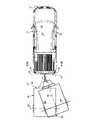
図1~図4を参照する。牽引車両10は、トレーラヒッチ27でトレーラ80に取り付けられている。牽引車両10は、前端12、後端14、乗員または右側16および運転者または左側18を含んでいる。いくつかの実施形態では、車両10は、センサシステム19を含んでおり、これは1つまたは複数の測定値を決定するために使用され得るセンサシステムデータ29を提供するセンサ20、22を含んでいる。センサシステム19は、1つまたは複数のセンサ20、22および/または1つまたは複数のカメラ26を含んでいてよい。センサ20、22はセンサデータ23を提供し、カメラは画像25を提供する。センサシステムデータ29はセンサデータ23および/または画像25を含んでいてよい。1つまたは複数のセンサ20、22には、超音波距離計、レーダー、ソナー、LIDAR(Light Detection and Ranging、これは遠隔ターゲットの距離および/または他の情報を見つけるために散乱光の特性を測定する光学リモートセンシングを必要とし得る)、LADAR(Laser Detection and Ranging)等が含まれ得るが、これらに限定されない。示されるように、第1のセンサ20および第2のセンサ22は、左側18および右側16の両方に沿って、牽引車両10の後端14に取り付けられている。しかし、車両10が、たとえば、車両の中心線28に沿って配置されている1つのセンサ20だけを支持してよい。付加的なセンサも可能であり得る。 1 to 4 will be referred to. The towing
いくつかの実施形態では、後向きカメラ26は、牽引車両10の後端14にも取り付けられているトレーラヒッチ27の上に取り付けられている。後向きカメラ26は、単眼カメラ、双眼カメラ、または牽引車両10の後方の走行経路の景色を提供することができる別のタイプのセンシングデバイスであってよい。後向きカメラ26は、車両10の後部環境の画像25を捕捉する。たとえば、トレーラ80が車両10に、トレーラヒッチ27で取り付けられている場合、カメラ26によって捕捉された画像25は、トレーラ80の前端90の表現を含んでいる。 In some embodiments, the
牽引車両10は、車両の全長を通り、右側16および左側18から実質的に等距離にある仮想線28である「中心線」を有している。いくつかの例では、トレーラヒッチ27はこの中心線28上に配置されている。したがって、トレーラ80は、牽引車両10に、牽引車両の中心線28で取り付けられている。 The towing
図1において、参照番号60によって識別される基準線は、中心線28に対して実質的に垂直であり、かつ牽引車両10の後端14と実質的に同一平面上にある「鉛直線」または想像上の線である。基準線62Aおよび62Bによって、カメラ26の視野が識別される。車両10とトレーラ80とが整列されているとき、すなわち、車両10とトレーラ80とが中心線28に沿って実質的に整列されているとき、車両10とトレーラ80との間のトレーラ角度αはゼロに等しい。しかし、トレーラ80と車両10とが整列されていない場合、車両10に対するトレーラ80の位置に応じて、このトレーラ角度αはゼロより大きいかまたは小さくなる。 In FIG. 1, the reference line identified by
車両10は、車両プロセッサ402、たとえば計算デバイスまたはデータ処理ハードウェアを含んでいる。これは、計算プロセッサ402上で実行可能な命令を格納することができる非一過性のメモリまたはハードウェアメモリ404、たとえばハードディスク、フラッシュメモリ、ランダムアクセスメモリと通信する1つまたは複数の計算プロセッサを有する中央処理ユニット等であるがこれらに限定されない。いくつかの例では、非一過性のメモリ404は命令を格納しており、この命令によって実行時にプロセッサ402は、受け取ったセンサシステムデータ29に基づいてトレーラ80の寸法を決定し、決定した寸法に基づいて、牽引車両10の後端14に取り付けられているトレーラ80の上面図のアニメーションを生成する。 The
ここでトレーラ80を参照すると、これも後端82、右側84、左側86、軸88および前端90を有している。前端90から延びるバー91がトレーラヒッチ27で牽引車両10に取り付けられる。 Referring here to the
いくつかの実施形態では、センサ20および22からの信号21(たとえば、音響信号または波)は、トレーラ80の左側86および右側84の前端90に当たり、反射される。信号21がセンサ20、22を出てトレーラの側面84、86に当たり、センサ20、22に戻るまでの経過時間は、「往復」時間を提供し、これによってプロセッサ402は、既知の音速を使用して、センサ20、22とトレーラ80の側面84、86との間の分離距離を計算することができる。いくつかの例では、各センサ20、22に対して、信号21の経過時間が異なる場合がある。これは、トレーラ80と車両10とが整列されておらず、車両10に対するトレーラ80の位置に応じて、トレーラ角度αがゼロより大きいまたはゼロより小さいことを示している。しかし、信号21に対する経過時間が等しい場合、プロセッサ402は、トレーラ80と車両10とが整列されており、トレーラ角度αがゼロに等しいことを決定する。さらに、プロセッサ402は、各信号21の経過時間に基づいてトレーラ角度αを決定してよい。したがって、基準線60ならびに中心線28に対する軸88の角度またはトレーラ角度αを、センサ20、22によって作成された距離または間隔測定値から決定することができる。他の実施形態では、プロセッサ402は、画像25を分析し、分離距離SDおよび/またはトレーラ角度αを決定してよい。 In some embodiments, the signal 21 (eg, an acoustic signal or wave) from the
引き続き図1および図2を参照する。牽引車両10は、全長L1、全幅W1および車両の軸の中心線28の間の距離であるホイールベースWBを有している。トレーラ80は、全長L2および全幅W2を有している。トレーラ80は、トレーラ80の前端90とトレーラヒッチ27または牽引車両10の後端14との間の距離として定義される分離距離SDによって、牽引車両10から分離されている。Continue to refer to FIGS. 1 and 2. The towing
いくつかの実施形態では、プロセッサ402は、センサシステム19から受け取ったセンサシステムデータ29(たとえば、センサデータ23および/または画像25)を分析することによって、トレーラ80の幅W2を決定する。いくつかの例では、プロセッサ402は、牽引車両10の後端14に取り付けられているカメラ26から受け取った画像25を分析することによってトレーラ80の幅W2を決定する。カメラ26は、トレーラの前端90のビデオの1つのフレームを捕捉し、プロセッサ402は、この捕捉された画像を、既知のトレーラ幅の1つまたは複数のテンプレート画像と比較する。例として、トレーラ80と牽引車両10との間の距離SDが長くなると、その捕捉された画像25によって表されるトレーラ80の見かけのサイズは低減するだろう。同じトレーラ80がカメラ26に近づくと、画像25によって捕捉される見かけのサイズは増大するだろう。既知の幅を有するトレーラの画像25が、牽引車両10の後方のトレーラの捕捉された画像と比較される場合、これらの2つの画像を比較することによってトレーラ幅を少なくとも推定することができる。In some embodiments, the
いくつかの実施形態では、運転者は、トレーラ幅W2を、乗員室に配置されている端末、たとえばユーザ運転者入力412に手動で入力してよく、またはその製造業者のモデル番号によって、トレーラの仕様または識別も入力されてよい。In some embodiments, the driver may manually enter the trailer width W2 into a terminal located in the passenger compartment, eg, the
さらに別の例では、プロセッサ402が、受け取った画像25を分析することによって、トレーラ80の幅W2を決定してよい。これはたとえば、画像25内のピクセルを分析することによって行われる。プロセッサ402がどのように幅W2を決定するのかに関係なく、トレーラ80の幅W2および長さL2を決定することは、牽引車両10およびトレーラ80のシミュレートされた俯瞰図を生成できるようにするために重要である。In yet another example, the
トレーラ80の長さL2が測定され、ユーザ運転者入力412を介して手動で入力されてよい。またトレーラ80の長さL2が、非一過性のメモリ404内に常駐する牽引車両データベース406内で「検索」されてよい。いくつかの例では、プロセッサ402は、センサシステムデータ29(たとえば、センサデータ23および/または画像25)を分析することによって、トレーラ80の長さL2を推定する。たとえば、トレーラ80が牽引車両10に対して、センサシステム19がトレーラの前端90および後端82の両方を「見る」ことができる角度αで配置されている場合、プロセッサ402は、トレーラ80の長さL2を推定することができる。いくつかの例では、プロセッサ402は、トレーラ80が牽引車両10に対して所定の角度αにあるときに捕捉された1つまたは複数の画像25を分析することによって、トレーラ80の長さL2を推定する。The length L2 of the
プロセッサ402が、トレーラ80の寸法を決定すると、すなわち、長さL2および幅W2、牽引車両10の後端14からの距離SDおよび車両の中心線28とトレーラの中心線89との間の角度αを決定すると、プロセッサ402は、牽引車両の中心線28に対するトレーラ80の位置を計算して、トレーラプロファイルまたはフットプリントの画像を生成することによって、牽引車両10の後端14に取り付けられているトレーラ80の上面図のアニメーションを生成する。When the
図3Aは、車両10がトレーラ80と実質的に整列されている第1の位置P1における牽引車両10およびトレーラ80を示している。換言すると、トレーラ角度はゼロである。図4Aを参照する。プロセッサが車両10およびトレーラ80の測定値を決定すると、プロセッサ402は、車両表現415aおよびトレーラ表現415bを含んでいる車両トレーラ表現415を生成する。車両トレーラ表現415は、車両10およびトレーラ80に比例している。たとえば、トレーラが車両長L1を上回る長さL2を有している場合、車両トレーラ表現415は、ディスプレイに示されるように、車両表現よりも長いトレーラ表現を示す。逆に、トレーラが車両長L1を下回る長さL2を有している場合、車両トレーラ表現415は、ディスプレイに示されるように、車両表現よりも短いトレーラ表現を示す。FIG. 3A shows the towing
図3Bは、トレーラ80が車両10に対してトレーラ角度αで配置されている第2の位置P2における牽引車両10およびトレーラ80を示している。図4Bは、図3Bに関連する車両トレーラ表現415を示している。示されているように、プロセッサ402は、トレーラ80の位置が車両10に対して変化するとき、またはトレーラ角度αが第1の位置P1から第2の位置P2に変化するとき、ディスプレイ414を更新する。プロセッサ402は、第1の信号21を使用して、トレーラ80の第1の側面前端84、90と車両後端14、すなわち第2のセンサ22との間の第1の距離を決定することによってトレーラ角度αを決定してよい。プロセッサ402は、第2の超音波信号21を使用して、第2の側面前端86、90と車両後端14、すなわち第1のセンサ20との間の第2の距離を決定してよい。次にプロセッサ402は、第1の距離と第2の距離との間の差に基づいて、トレーラ角度αを計算することができる。 FIG. 3B shows the towing
図4は、図1~図3Cにおいて説明したような、牽引車両10およびトレーラ80の俯瞰図415をシミュレートする装置400のブロック図である。以下に説明するように、さまざまなコンポーネントが必然的に車両の後端に配置されており、また他のコンポーネントは乗員室内に配置されている。プロセッサおよび関連するメモリデバイスは、事実上どこにでも配置可能である。 FIG. 4 is a block diagram of a
装置400は、車両プロセッサ402と、プロセッサ402のためのプログラム命令を格納する非一過性のメモリ404とを含んでいる。上述したように、プロセッサ402が、格納されている命令を実行すると、命令によって、プロセッサ402はとりわけ、上述したように、俯瞰図415の計算および生成を実行する。 The
プログラム命令を格納することに加えて、非一過性のメモリ404は、牽引車両データベース406を含んでいてよく、その内容は、トレーラを牽引することができる自動車の物理的特性を含んでいる。このような特性には、車両の全長L1、その全幅W1およびそのホイールベースWBが含まれ得るが、これらに限定されない。プロセッサ402は、これらの特性を使用して、俯瞰画像415を生成する。In addition to storing program instructions, the
非一過性のメモリ404はまた、トレーラデータベース408を格納してよい。これは、牽引車両データベース406と同様に、製造業者によるトレーラのリストまたはテーブルであり、トレーラ長、幅、軸の数および牽引バーの長さを含んでいる。牽引バーは、トレーラの前端およびそのヒッチから延在する。容易なアクセスのために、データベースを、以前に使用されたトレーラのみを含むように縮小してよい。ここでこれは、運転者によって入力された値か、またはユーザが入力せずにシステムによって決定された値を備える。 The
いくつかの実施形態では、ディスプレイデバイス414は、プロセッサ402と通信する。ディスプレイデバイス414は、牽引車両10のダッシュボードに配置されていてよい。ディスプレイデバイス414は、タッチスクリーンディスプレイであってよい。 In some embodiments, the
プロセッサ402、非一過性のメモリ404およびディスプレイデバイス414は、従来のアドレス/データ/コントロールバス410を介して相互に通信してよい。いくつかの例では、バス410は、プロセッサ402をユーザ入力デバイスに結合する。これは、同様に乗員室内、たとえばダッシュボードに配置されているキーボード412等である。ユーザ入力デバイス412は、車両10の運転者または他の乗員が、牽引車両10、トレーラ80の物理的な特性および牽引車両10とトレーラ80との間の間隔SDを手動で入力することを可能にする。 The
いくつかの例では、左側のセンサ20および右側のセンサ22ならびにカメラ26も、同じコントロールバス416を介してプロセッサ402と通信する。上述したように、センサ20および22によって、両方の車両10、80の側面16、18、84、86に沿った、牽引車両10の後端14とトレーラ80の前端90との間の距離が正確に決定される。プロセッサ402は、カメラ26から画像を受け取り、受け取った画像に基づいて、プロセッサ402は、トレーラ幅W2、牽引車両10とトレーラ80との間の分離距離SDを決定する。さらに、プロセッサ402は、カメラ26によって捕捉された画像に基づいて、牽引車両10の中心線28とトレーラ80との間の角度を決定してよい。In some examples, the
いくつかの例では、車両10は運転者ステアリングホイール角度入力デバイス418を含んでおり、これはたとえば、車両ダッシュボード上の回転ノブまたは車両のステアリングホイールに結合されている位置センサ等である。ステアリングホイール角度入力デバイス418は、プロセッサ402と通信する。いくつかの例では、ステアリングホイール角度入力デバイス418は、コントロールバス410を介してプロセッサに結合されている。ステアリングホイール角度入力デバイス418は、牽引車両10のステアリング角度の変化を表す信号を提供する。 In some examples, the
牽引車両が前方に駆動されているときに、ステアリングホイールを時計回りに回転させると、車両が右に曲がるか右に「進む」ことは当業者に既知である。逆に、ステアリングホイールを反時計回りに回転させると、車両が左に曲がるか左に「進む」。 It is known to those skilled in the art that rotating the steering wheel clockwise while the towing vehicle is being driven forward will cause the vehicle to turn to the right or "go" to the right. Conversely, turning the steering wheel counterclockwise causes the vehicle to turn left or "go" to the left.
トレーラ80が取り付けられている牽引車両10が後退するとき、すなわち、後ろ向きに駆動されているときには、車両10のステアリングホイールの時計回りまたは反時計回りの回転によって、取り付けられているトレーラ80は反対方向に向けられる。換言すると、ステアリングホイールを時計回りに回転させると、牽引車両10が後ろ向きに動き、取り付けられているトレーラ80を「左」に押す。ステアリングホイールを反時計回りに回転させると、牽引車両10が後ろ向きに動き、取り付けられているトレーラ80を「右」に押す。 When the towing
いくつかの実施形態では、ステアリングホイール角度入力デバイス418は、ステアリングホイール角度信号をプロセッサ402に伝送する。プロセッサ402は、車両の中心線28とトレーラの軸88との間の角度の変化を計算する。さらに、プロセッサ402は、トレーラ角度αの変化に基づいて、トレーラ80および車両10の上面図のアニメーションを生成する。したがって、運転者は、ステアリングホイール角度に応じてトレーラ80がどのように動くのかをディスプレイ414上で見ることができる。いくつかの例では、運転者がステアリングホイール角度を変更するときに、トレーラ角度αおよび俯瞰図415がリアルタイムで更新される。しかし、図3Eに示されているような他の例では、運転者がステアリングホイール角度を変更するときに、俯瞰図415だけが更新され、その後、運転者の入力後に、牽引車両10が後方または前方に移動している間にトレーラ角度αも変化する。このような場合、トレーラ80のゴースト画像145bb(すなわち、第2のトレーラ表現)が、実際のトレーラ表現415bの位置に重なる場合がある。示されているように、プロセッサ402は、車両10およびトレーラ80の寸法を考慮するので、プロセッサ402は、ジャックナイフ現象に関する警告を運転者に提供し得る。 In some embodiments, the steering wheel
ここで図5を参照する。図5は、図1~図4において説明した牽引車両10およびトレーラ80の俯瞰図をシミュレートする方法500を示す。ブロック502で、車両10の後端14に配置されているカメラ26が、牽引車両10の後ろに配置されているトレーラ80の画像を捕捉する。カメラ26は、捕捉された画像の少なくとも1つのフレームをプロセッサ402に送る。 Now refer to FIG. FIG. 5 shows a
ブロック504で、トレーラ80の幅W2が決定される。トレーラ80の幅W2は、たとえば、運転者によって入力されるキーボード等の入力デバイス412を介して受け取られてよい。いくつかの例では、トレーラ80の幅W2は、トレーラ80の画像をデータベース408内に格納されている1つまたは複数の事前に捕捉された画像と比較することによって決定される。プロセッサ402は、捕捉された画像を、関連付けられたトレーラ長を有するトレーラを識別する、事前に捕捉された画像と比較する。他の例では、プロセッサ402は、車両10の後端14に配置されている1つまたは複数のセンサからセンサデータ23を受け取る。プロセッサ402は、受け取ったセンサデータ23に基づいてトレーラ80の幅W2を決定する。ブロック506で、プロセッサ402は、牽引車両10とトレーラ80との間の距離SDを決定する。いくつかの例では、プロセッサ402は、運転者入力を介してキーボード412から、牽引車両10とトレーラ80との間の距離SDを受け取る。他の例では、プロセッサ402は、車両10の後端14に配置されている1つまたは複数のセンサからセンサデータ23を受け取り、受け取ったセンサデータ23に基づいて、プロセッサ402は牽引車両10とトレーラ80との間の距離SDを決定する。At
ブロック508で、プロセッサ402は、運転者入力デバイス418によるステアリング角度の変化に応じて、車両の中心線28とトレーラの軸88との間の角度の変化を計算する。ステップ512で、プロセッサ402は、アニメーションまたはビデオ画像を生成する。上述したアニメーションは、それがビデオであろうと1つの静止画像であろうと、ステップ514において、たとえば、乗員室のダッシュボード上にあるディスプレイパネル上に表示される。最後に、ステップ516で、プロセッサ402は、車両10が駐車されているか否かを判定する。本明細書で使用されるとき、用語「駐車されている」とは、車両が保管されるだろう最終的な場所へ移動されていることを意味する。車両10が駐車されていない場合、この方法500はステップ510に戻り、ダッシュボードに取り付けられている入力デバイスまたはステアリングホイール自体から異なるステアリング角度入力信号を受信する。 At
いくつかの実施形態では、車両10は、共有ネットワーク(図示せず)を介して他の車両またはデバイスと通信する。共有ネットワークは、通信信号の送信および受信を可能にする任意のタイプのネットワークを含んでいてよく、これは無線通信ネットワーク、携帯電話ネットワーク、時分割多元接続(TDMA)ネットワーク、符号分割多元接続(CDMA)ネットワーク、汎欧州デジタル移動電話方式(GSM)、第3世代移動通信システム(3G)ネットワーク、第4世代移動通信システム(4G)ネットワーク、衛星通信網および他の通信ネットワーク等である。共有ネットワークは、ワイド・エリア・ネットワーク(WAN)、ローカル・エリア・ネットワーク(LAN)およびパーソナル・エリア・ネットワーク(PAN)のうちの1つまたは複数を含んでいてよい。いくつかの例では、共有ネットワークは、データネットワーク、電気通信ネットワークおよびデータと電気通信ネットワークとの組み合わせを含んでいる。共有ネットワークは、処理ユニットおよび/またはストレージリソース等のクラウド計算リソースへのアクセスを提供する。用語「クラウド」サービスは一般的に、車両上でローカルに実行されるサービスではなく、1つまたは複数のネットワークを介してアクセス可能な1つまたは複数のリモートデバイスから配信されるサービスを指す。 In some embodiments, the
いくつかの実施形態では、ネットワークは、車両10と他の車両との間の車車間(V2V)通信を提供する。車両10、すなわちプロセッサ402は、ネットワークを介して1つまたは複数の車両からデータを受け取り、受け取ったデータを分析するように構成されている。いくつかの例では、受け取ったデータは、現在の牽引車両10に関連する情報を含んでいる。このようなケースでは、プロセッサ402は、受け取ったデータを使用して鳥瞰図を生成し、車両およびトレーラのより正確なレンダリングを提供する。いくつかの例では、プロセッサ402は、車両10によってサポートされるセンサ20、22からセンサデータ23を受け取り、受け取ったセンサデータ23およびV2V通信を介して他の車両から提供されたデータに基づいて、プロセッサ402は、鳥瞰図のより良いレンダリングを提供する。 In some embodiments, the network provides vehicle-to-vehicle (V2V) communication between
図6は、図1~図5のシステムを使用して牽引車両10および牽引車両10に取り付けられているトレーラ80の俯瞰図415を生成する方法600の動作の例示的な段取りを提供する。ブロック602で、方法600は、処理ハードウェア402、402で、処理ハードウェア402と通信するセンサシステム19から第1のセンサシステムデータ29を受け取る。センサシステム19は、センサ20、22および/またはカメラ26を含んでいる。第1のセンサシステムデータ29は、牽引車両10に対する第1のトレーラ位置P1に関連付けられている。ブロック604で、方法600は、処理ハードウェア402で、第1のセンサシステムデータ29に基づいてトレーラ幅W2を決定することを含んでいる。ブロック606で、方法600は、処理ハードウェア402で、センサシステム19から第2のセンサシステムデータ29を受け取ることを含んでいる。第2のセンサシステムデータ29は、牽引車両10に対する第2のトレーラ位置P2に関連付けられている。ブロック608で、方法600は、処理ハードウェア402で、第2のセンサデータに基づいてトレーラ長L2を決定することを含んでいる。ブロック610で、方法600は、処理ハードウェア402で、第1のセンサシステムデータ29および/または第2のセンサシステムデータ29に基づいて、トレーラ80と牽引車両10との間の分離距離SDを決定することを含んでいる。ブロック612で、方法600は、処理ハードウェア402と通信するハードウェアメモリ404から、車両長L1および車両幅W1を読み出すことを含んでいる。ブロック614で、方法600は、処理ハードウェア402で、トレーラ幅W2、トレーラ長L2、分離距離SD、車両長L1および車両幅W1に基づいて、車両表現415aおよびトレーラ表現415bを含んでいる俯瞰画像415を生成することを含んでいる。ブロック616で、方法600は、処理ハードウェア402から、処理ハードウェア402と通信するディスプレイ414に、俯瞰画像415を表示するための命令を伝送することを含んでいる。FIG. 6 provides an exemplary setup of the operation of
いくつかの実施形態では、方法600はさらに、処理ハードウェア402で、処理ハードウェア402と通信するステアリングホイール角度入力デバイス418(たとえば、回転ノブ)からステアリングホイール角度419を受け取ることを含んでいる。方法700は、処理ハードウェア402で、ステアリングホイール角度に基づいて俯瞰画像25を調整することを含んでいる。 In some embodiments, the
いくつかの例では、方法600は、処理ハードウェア402で、処理ハードウェア402と通信するステアリングホイール角度入力デバイス418(たとえば、回転ノブ)からステアリングホイール角度419を受け取ることを含んでいる。方法600は、処理ハードウェア402で、ステアリングホイール角度419に基づいてトレーラ表現415bの位置を決定することを含んでいる。方法600はまた、処理ハードウェア402で、車両表現415a、トレーラ表現415bおよび投影されたトレーラ表現415bbを含んでいる更新された俯瞰画像415を生成することを含んでいる。投影されたトレーラ表現415bbは、ステアリングホイール角度419を実行した後のトレーラの位置を示す。 In some examples, the
図7は、図1~図5のシステムを使用して牽引車両10および牽引車両10に取り付けられているトレーラ80の俯瞰図415を生成する方法700の動作の例示的な段取りを提供する。ブロック702で、方法700は、処理ハードウェア402で、牽引車両10の後部環境を捕捉するために、牽引車両10の後端14に配置されているカメラ26から、第1の画像25を受け取ることを含んでいる。第1の画像25は、トレーラ80の前端90を含んでいる。ブロック704で、方法700は、処理ハードウェア402で、第1の画像25に基づいてトレーラ幅W2を決定することを含んでいる。ブロック706で、方法700は、処理ハードウェア402で、カメラ26からの第2の画像25を受け取ることを含んでいる。第2の画像25は、トレーラ80の側面84、86および前端90を含んでいる。ブロック708で、方法700は、処理ハードウェア402で、第2の画像25に基づいてトレーラ長L2を決定することを含んでいる。ブロック710で、方法700は、処理ハードウェア402で、牽引車両10の後端14に配置されている1つまたは複数のセンサ20、22からセンサデータ23を受け取ることを含んでいる。ブロック712で、方法700は、処理ハードウェア402で、センサデータ23に基づいて、トレーラ80と牽引車両10との間の分離距離SDを決定することを含んでいる。さらに、ブロック714で、方法700は、処理ハードウェア402と通信するハードウェアメモリ404から、車両長L1および車両幅W1を読み出すことを含んでいる。ブロック716で、方法700は、処理ハードウェア402で、トレーラ幅W2、トレーラ長L2、分離距離SD、車両長L1および車両幅W1に基づいて、車両表現415aおよびトレーラ表現415bを含んでいる俯瞰画像415を生成することを含んでいる。ブロック718で、方法700は、処理ハードウェア402から、処理ハードウェア402と通信するディスプレイ414に、俯瞰画像415を表示するための命令を伝送することを含んでいる。FIG. 7 provides an exemplary setup of the operation of the
いくつかの実施形態では、車両表現415aおよびトレーラ表現415bは、牽引車両10およびトレーラ80にそれぞれ比例している。 In some embodiments, the
いくつかの実施形態では、方法700はさらに、処理ハードウェア402で、処理ハードウェア402と通信するステアリングホイール角度入力デバイス418(たとえば、回転ノブ)からステアリングホイール角度419を受け取ることを含んでいる。方法700は、処理ハードウェア402で、ステアリングホイール角度に基づいて俯瞰画像25を調整することを含んでいる。 In some embodiments, the
いくつかの例では、方法700は、処理ハードウェア402で、処理ハードウェア402と通信するステアリングホイール角度入力デバイス418(たとえば、回転ノブ)からステアリングホイール角度419を受け取ることを含んでいる。方法700は、処理ハードウェア402で、ステアリングホイール角度419に基づいてトレーラ表現415bの位置を決定することを含んでいる。方法700はまた、処理ハードウェア402で、車両表現415a、トレーラ表現415bおよび投影されたトレーラ表現415bbを含んでいる更新された俯瞰画像415を生成することを含んでいる。投影されたトレーラ表現415bbは、ステアリングホイール角度419を成した後のトレーラの位置を示す。 In some examples, the
いくつかの実施形態では、カメラ26は、牽引車両10およびトレーラ80が第1の位置にあるときに第1の画像25を捕捉し、牽引車両10およびトレーラ80が第2の位置にあるときに第2の画像25を捕捉する。いくつかの例では、分離距離SDを決定することは、センサ信号21が1つまたは複数のセンサ20、22から1つまたは複数のセンサ20、22に戻るまでの経過時間を計算することを含んでいる。 In some embodiments, the
方法700はさらに、処理ハードウェア402で、ネットワークを介して、処理ハードウェア402と通信する1つまたは複数の車両から車両センサデータを受け取ることを含んでいてよい。方法700はまた、処理ハードウェア402で、トレーラ幅W2、トレーラ長L2、分離距離SD、車両長L1、車両幅W1および車両センサデータに基づいて俯瞰画像415を生成することを含んでいる。ネットワークは、処理ハードウェア402と他の車両との間の車車間通信を提供するように構成されていてよい。
本明細書で説明したシステムおよび技法のさまざまな実施形態は、デジタル電子回路、集積回路、特別に設計されたASIC(特定用途向け集積回路)、コンピュータハードウェア、ファームウェア、ソフトウェアおよび/またはそれらの組み合わせで実現できる。これらのさまざまな実施形態は、プログラミング可能なシステム上で実行可能、かつ/または解釈可能な1つまたは複数のコンピュータプログラムでの実施形態を含み得る。これは少なくとも1つのプログラミング可能なプロセッサを含んでおり、このプロセッサは、ストレージシステム、少なくとも1つの入力デバイスおよび少なくとも1つの出力デバイスからデータおよび命令を受け取り、それらにデータおよび命令を伝送するように結合された、特殊なまたは汎用の目的のものであってよい。 Various embodiments of the systems and techniques described herein include digital electronic circuits, integrated circuits, specially designed ASICs (application specific integrated circuits), computer hardware, firmware, software and / or combinations thereof. Can be realized with. These various embodiments may include embodiments in one or more computer programs that are executable and / or interpretable on a programmable system. It contains at least one programmable processor that receives data and instructions from the storage system, at least one input device and at least one output device and combines them to transmit the data and instructions. It may be for special or general purpose purposes.
これらのコンピュータプログラム(プログラム、ソフトウェア、ソフトウェアアプリケーションまたはコードとしても知られている)は、プログラミング可能なプロセッサのための機械命令を含み、高水準の手続き型および/またはオブジェクト指向プログラミング言語で、かつ/またはアセンブリ/機械語で実装可能である。本明細書で使用される場合、用語「機械可読媒体」および「コンピュータ可読媒体」は、機械命令を機械可読信号として受け取る機械可読媒体を含んでいる、プログラミング可能なプロセッサに機械命令および/またはデータを提供するために使用される任意のコンピュータプログラム製品、装置および/またはデバイス(たとえば、磁気ディスク、光ディスク、メモリ、プログラマブルロジックデバイス(PLD))を指す。用語「機械可読信号」は、プログラミング可能なプロセッサに機械命令および/またはデータを提供するために使用される任意の信号を指す。 These computer programs (also known as programs, software, software applications or code) include machine instructions for programmable processors, are in a high-level procedural and / or object-oriented programming language, and / Or it can be implemented in assembly / machine language. As used herein, the terms "machine-readable medium" and "computer-readable medium" include machine-readable media that receive machine instructions as machine-readable signals, machine instructions and / or data to a programmable processor. Refers to any computer program product, device and / or device (eg, magnetic disk, optical disk, memory, programmable logic device (PLD)) used to provide. The term "machine readable signal" refers to any signal used to provide machine instructions and / or data to a programmable processor.
本明細書で説明された主題および機能動作の実施形態は、本明細書で開示される構造およびそれらの構造的等価物を含んでいる、デジタル電子回路もしくはコンピュータソフトウェア、ファームウェアもしくはハードウェア、またはそれらのうちの1つまたは複数の組み合わせで実装可能である。さらに、本明細書で説明された主題は、1つまたは複数のコンピュータプログラム製品、すなわち、コンピュータプログラム命令の1つまたは複数のモジュールとして実装可能である。これは、データ処理装置による実行のため、またはデータ処理装置の動作をコントロールするためにコンピュータ可読媒体に符号化されている。コンピュータ可読媒体は、機械可読ストレージデバイス、機械可読ストレージ基板、メモリデバイス、機械可読伝播信号をもたらす組成物、またはそれらのうちの1つまたは複数の組み合わせであり得る。用語「データ処理装置」、「計算デバイス」および「計算プロセッサ」は、例として、プログラミング可能なプロセッサ、コンピュータ、またはマルチプロセッサもしくはコンピュータを含んでいる、データを処理するためのすべての装置、デバイスおよび機械を包含する。装置は、ハードウェアに加えて、議論されているコンピュータプログラムの実行環境を作成するコード、たとえば、プロセッサファームウェア、プロトコルスタック、データベース管理システム、オペレーティングシステム、またはそれらのうちの1つまたは複数の組み合わせを構成するコードを含むことができる。伝播信号は、人工的に生成された信号、たとえば、適切な受信装置への伝送のために情報を符号化するために生成された、機械によって生成された電気信号、光学信号または電磁信号である。 Embodiments of the subject matter and functional operation described herein are digital electronic circuits or computer software, firmware or hardware, or them, comprising the structures disclosed herein and their structural equivalents. It can be implemented in one or more combinations of the above. Further, the subject matter described herein can be implemented as one or more computer program products, i.e., one or more modules of computer program instructions. It is encoded on a computer-readable medium for execution by the data processing device or to control the operation of the data processing device. The computer-readable medium can be a machine-readable storage device, a machine-readable storage board, a memory device, a composition that provides a machine-readable propagation signal, or a combination thereof. The terms "data processor", "computational device" and "computational processor", for example, include programmable processors, computers, or multiprocessors or computers, all devices, devices and devices for processing data. Including machines. In addition to the hardware, the device contains code that creates the execution environment for the computer programs being discussed, such as processor firmware, protocol stacks, database management systems, operating systems, or a combination of one or more of them. Can include constituent code. A propagating signal is an artificially generated signal, eg, a machine-generated electrical, optical or electromagnetic signal generated to encode information for transmission to a suitable receiver. ..
同様に、動作が特定の順序で図面に示されているが、これは、所望の結果を得るために、そのような動作を示された特定の順序で、または順次に実行すること、またはすべての図示された動作を実行することを要求するものとして理解されるべきではない。特定の状況では、マルチタスキングおよび並列処理が有利な場合がある。さらに、上述した実施形態におけるさまざまなシステムコンポーネントの分離は、すべての実施形態におけるそのような分離を要求するものとして理解されるべきではなく、説明されたプログラムコンポーネントおよびシステムがともに、一般的に1つのソフトウェア製品に統合可能であること、または複数のソフトウェア製品にパッケージ可能であることが理解されるべきである。 Similarly, the actions are shown in the drawings in a particular order, but this is to perform such actions in the particular order shown, or in sequence, or all to obtain the desired result. Should not be understood as requiring the performance of the illustrated actions of. In certain situations, multitasking and parallelism may be advantageous. Moreover, the separation of the various system components in the embodiments described above should not be understood as requiring such separation in all embodiments, and both the program components and systems described are generally 1. It should be understood that it can be integrated into one software product or packaged into multiple software products.
いくつかの実施形態が説明されてきたが、本開示の趣旨および範囲から逸脱することなく、さまざまな修正を行うことができることが理解されよう。したがって、他の実施形態は、以降の特許請求の範囲の範囲内にある。 Although some embodiments have been described, it will be appreciated that various modifications can be made without departing from the spirit and scope of the present disclosure. Therefore, other embodiments are within the scope of the subsequent claims.
Claims (19)
Translated fromJapanese処理ハードウェアで、前記処理ハードウェアと通信するセンサシステムから、前記牽引車両に対する第1のトレーラ位置に関連付けられている第1のセンサシステムデータを受け取るステップと、
前記処理ハードウェアで、前記第1のセンサシステムデータに基づいてトレーラ幅を決定するステップと、
前記処理ハードウェアで、前記センサシステムから、前記牽引車両に対する前記トレーラのトレーラ角度が前記第1のトレーラ位置とは異なる第2のトレーラ位置に関連付けられている第2のセンサシステムデータを受け取るステップと、
前記処理ハードウェアで、前記第2のセンサシステムデータに基づいてトレーラ長を決定するステップと、
前記処理ハードウェアで、前記第1のセンサシステムデータおよび/または前記第2のセンサシステムデータに基づいて、前記トレーラと前記牽引車両との間の分離距離を決定するステップと、
前記処理ハードウェアと通信するハードウェアメモリから、車両長および車両幅を読み出すステップと、
前記処理ハードウェアで、前記トレーラ幅、前記トレーラ長、前記分離距離、前記車両長および前記車両幅に基づいて、車両表現およびトレーラ表現を含む俯瞰画像を生成するステップと、
前記処理ハードウェアから、前記処理ハードウェアと通信するディスプレイに、前記俯瞰画像を表示するための命令を伝送するステップと、
を含み、
前記処理ハードウェアは、前記第1のセンサシステムデータに含まれる前記トレーラの前端を含む画像に基づいて、前記トレーラ幅を決定し、
前記処理ハードウェアは、前記第2のセンサシステムデータに含まれる前記トレーラの側面と前端とを含む画像に基づいて、前記トレーラ長を決定し、
前記トレーラの前端を含む画像と、前記トレーラの側面と前端とを含む画像とは、同一のカメラにより捕捉される、
方法。A method of generating a bird's-eye view of a towing vehicle and a trailer attached to the towing vehicle.
The step of receiving the first sensor system data associated with the first trailer position with respect to the towing vehicle from the sensor system communicating with the processing hardware in the processing hardware.
In the processing hardware, the step of determining the trailer width based on the first sensor system data, and
With the processing hardware, the step of receiving from the sensor system the second sensor system data associated with a second trailer position where the trailer angle of the trailer with respect to the towing vehicle is different from the first trailer position. ,
In the processing hardware, the step of determining the trailer length based on the second sensorsystem data, and
In the processing hardware, a step of determining the separation distance between the trailer and the towing vehicle based on the first sensor system data and / or the second sensor system data.
A step of reading the vehicle length and the vehicle width from the hardware memory that communicates with the processing hardware,
A step of generating a bird's-eye view image including a vehicle representation and a trailer representation on the processing hardware based on the trailer width, the trailer length, the separation distance, the vehicle length and the vehicle width.
A step of transmitting an instruction for displaying the bird's-eye view image from the processing hardware to a display communicating with the processing hardware.
Including
The processing hardware determines the trailer width based on an image including the front end of the trailer contained in the first sensor system data.
The processing hardware determines the trailer length based on an image including the side and front ends of the trailer included in the second sensor system data.
The image including the front end of the trailer and the image including the side surface and the front end of the trailer are captured by the same camera.
Method.
前記処理ハードウェアで、前記ステアリングホイール角度に基づいて前記俯瞰画像を調整するステップと、
をさらに含む、請求項1記載の方法。The step of receiving the steering wheel angle from the steering wheel angle input device that communicates with the processing hardware in the processing hardware.
With the processing hardware, the step of adjusting the bird's-eye view image based on the steering wheel angle, and
The method according to claim1 , further comprising.
前記処理ハードウェアで、前記ステアリングホイール角度に基づいて、前記トレーラ表現の位置を決定するステップと、
前記処理ハードウェアで、前記車両表現、前記トレーラ表現および投影されたトレーラ表現を含む更新された俯瞰画像を生成するステップと、
をさらに含み、
前記投影されたトレーラ表現は、前記ステアリングホイール角度における前記トレーラの位置を示す、
請求項1記載の方法。The step of receiving the steering wheel angle from the steering wheel angle input device that communicates with the processing hardware in the processing hardware.
In the processing hardware, the step of determining the position of the trailer representation based on the steering wheel angle, and
A step of generating an updated bird's-eye view image containing the vehicle representation, the trailer representation, and the projected trailer representation in the processing hardware.
Including
The projected trailer representation indicates the position of the trailer at the steering wheel angle.
The method according to claim1 .
処理ハードウェアで、前記牽引車両の後部環境を捕捉するために、前記牽引車両の後端に配置されているカメラから、前記トレーラの前端を含む第1の画像を受け取るステップと、
前記処理ハードウェアで、前記第1の画像に基づいてトレーラ幅を決定するステップと、
前記処理ハードウェアで、前記カメラから、前記トレーラの側面と前記前端とを含み、前記牽引車両に対する前記トレーラのトレーラ角度が前記第1の画像とは異なる第2の画像を受け取るステップと、
前記処理ハードウェアで、前記第2の画像に基づいてトレーラ長を決定するステップと、
前記処理ハードウェアで、前記牽引車両の前記後端に配置されている1つまたは複数のセンサからセンサ情報を受け取るステップと、
前記処理ハードウェアで、前記センサ情報に基づいて、前記トレーラと前記牽引車両との間の分離距離を決定するステップと、
前記処理ハードウェアと通信するハードウェアメモリから、車両長および車両幅を読み出すステップと、
前記処理ハードウェアで、前記トレーラ幅、前記トレーラ長、前記分離距離、前記車両長および前記車両幅に基づいて、車両表現およびトレーラ表現を含んでいる俯瞰画像を生成するステップと、
前記処理ハードウェアから、前記処理ハードウェアと通信するディスプレイに、前記俯瞰画像を表示するための命令を伝送するステップと、
を含む、方法。A method of generating a bird's-eye view of a towing vehicle and a trailer attached to the towing vehicle.
A step of receiving a first image, including the front end of the trailer, from a camera located at the rear end of the tow vehicle in order to capture the rear environment of the tow vehicle in the processing hardware.
In the processing hardware, the step of determining the trailer width based on the first image, and
A step of receiving from the camera a second image from the camera that includes the side surface and the front end of the trailer and the trailer angle of the trailer with respect to the towing vehicle is different from the first image.
In the processing hardware, the step of determining the trailer length based on the second image, and
A step of receiving sensor information from the processing hardware from one or more sensors located at the rear end of the towing vehicle.
A step of determining the separation distance between the trailer and the towing vehicle based on the sensor information in the processing hardware.
A step of reading the vehicle length and the vehicle width from the hardware memory that communicates with the processing hardware,
A step of generating a bird's-eye view image containing a vehicle representation and a trailer representation on the processing hardware based on the trailer width, the trailer length, the separation distance, the vehicle length and the vehicle width.
A step of transmitting an instruction for displaying the bird's-eye view image from the processing hardware to a display communicating with the processing hardware.
Including, how.
前記処理ハードウェアで、前記ステアリングホイール角度に基づいて前記俯瞰画像を調整するステップと、
をさらに含む、請求項4または5記載の方法。The step of receiving the steering wheel angle from the steering wheel angle input device that communicates with the processing hardware in the processing hardware.
With the processing hardware, the step of adjusting the bird's-eye view image based on the steering wheel angle, and
4. The method of claim4 or5 , further comprising.
前記処理ハードウェアで、前記ステアリングホイール角度に基づいて、前記トレーラ表現の位置を決定するステップと、
前記処理ハードウェアで、前記車両表現、前記トレーラ表現および投影されたトレーラ表現を含む更新された俯瞰画像を生成するステップと、
を含み、
前記投影されたトレーラ表現は、前記ステアリングホイール角度での前記トレーラの位置を示す、
請求項4または5記載の方法。The step of receiving the steering wheel angle from the steering wheel angle input device that communicates with the processing hardware in the processing hardware.
In the processing hardware, the step of determining the position of the trailer representation based on the steering wheel angle, and
A step of generating an updated bird's-eye view image containing the vehicle representation, the trailer representation, and the projected trailer representation in the processing hardware.
Including
The projected trailer representation indicates the position of the trailer at the steering wheel angle.
The method according to claim4 or5 .
前記処理ハードウェアで、前記トレーラ幅、前記トレーラ長、前記分離距離、前記車両長、前記車両幅および前記車両センサデータに基づいて前記俯瞰画像を生成するステップと、
をさらに含む、請求項4から9までのいずれか1項記載の方法。A step in which the processing hardware receives vehicle sensor data from one or more vehicles communicating with the processing hardware over a network.
A step of generating the bird's-eye view image based on the trailer width, the trailer length, the separation distance, the vehicle length, the vehicle width, and the vehicle sensor data in the processing hardware.
The method according to any one of claims4 to9 , further comprising.
運転者ディスプレイと、
前記運転者ディスプレイと通信する処理ハードウェアと、
前記処理ハードウェアと通信するハードウェアメモリと、
を含み、
前記ハードウェアメモリは命令を格納しており、前記命令は実行時に、前記処理ハードウェアに方法を実施させ、前記方法は、
前記牽引車両の後部環境を捕捉するために、前記牽引車両の後端に配置されているカメラから、前記トレーラの前端を含む第1の画像を受け取るステップと、
前記第1の画像に基づいてトレーラ幅を決定するステップと、
前記カメラから、前記トレーラの側面と前記前端とを含み、前記牽引車両に対する前記トレーラのトレーラ角度が前記第1の画像とは異なる第2の画像を受け取るステップと、
前記第2の画像に基づいてトレーラ長を決定するステップと、
前記牽引車両の前記後端に配置されている1つまたは複数のセンサからセンサデータを受け取るステップと、
前記センサデータに基づいて、前記トレーラと前記牽引車両との間の分離距離を決定するステップと、
前記ハードウェアメモリから、車両長および車両幅を読み出すステップと、
前記トレーラ幅、前記トレーラ長、前記分離距離、前記車両長および前記車両幅に基づいて、車両表現およびトレーラ表現を含む俯瞰画像を生成するステップと、
前記運転者ディスプレイに、前記俯瞰画像を表示するための命令を伝送するステップと、
を含む、
システム。A system that generates a bird's-eye view of a towing vehicle and a trailer attached to the towing vehicle.
With the driver display,
The processing hardware that communicates with the driver display,
The hardware memory that communicates with the processing hardware,
Including
The hardware memory stores an instruction, and the instruction causes the processing hardware to execute the method at the time of execution.
A step of receiving a first image including the front end of the trailer from a camera located at the rear end of the tow vehicle to capture the rear environment of the tow vehicle.
The step of determining the trailer width based on the first image and
A step of receiving a second image from the camera, including the side surface of the trailer and the front end, where the trailer angle of the trailer with respect to the towing vehicle is different from the first image.
The step of determining the trailer length based on the second image and
A step of receiving sensor data from one or more sensors located at the rear end of the towing vehicle.
A step of determining the separation distance between the trailer and the towing vehicle based on the sensor data, and
A step of reading the vehicle length and the vehicle width from the hardware memory,
A step of generating a bird's-eye view image including a vehicle representation and a trailer representation based on the trailer width, the trailer length, the separation distance, the vehicle length and the vehicle width.
A step of transmitting a command for displaying the bird's-eye view image on the driver display, and
including,
system.
前記処理ハードウェアと通信するステアリングホイール角度入力デバイスからステアリングホイール角度を受け取るステップと、
前記ステアリングホイール角度に基づいて前記俯瞰画像を調整するステップと、
を含む、請求項12または13記載のシステム。The method further
The step of receiving the steering wheel angle from the steering wheel angle input device that communicates with the processing hardware,
The step of adjusting the bird's-eye view image based on the steering wheel angle,
12. The system according to claim12 or13 .
前記処理ハードウェアと通信するステアリングホイール角度入力デバイスからステアリングホイール角度を受け取るステップと、
前記ステアリングホイール角度に基づいて前記トレーラ表現の位置を決定するステップと、
前記車両表現、前記トレーラ表現および投影されたトレーラ表現を含む更新された俯瞰画像を生成するステップと、
を含み、
前記投影されたトレーラ表現は、前記ステアリングホイール角度での前記トレーラの位置を示す、
請求項12または13記載のシステム。The method further
The step of receiving the steering wheel angle from the steering wheel angle input device that communicates with the processing hardware,
A step of determining the position of the trailer representation based on the steering wheel angle,
A step of generating an updated bird's-eye view image including the vehicle representation, the trailer representation, and the projected trailer representation.
Including
The projected trailer representation indicates the position of the trailer at the steering wheel angle.
The system according to claim12 or13 .
ネットワークを介して、前記処理ハードウェアと通信する1つまたは複数の車両から車両センサデータを受け取るステップと、
前記トレーラ幅、前記トレーラ長、前記分離距離、前記車両長、前記車両幅および前記車両センサデータに基づいて前記俯瞰画像を生成するステップと、
を含む、請求項12から17までのいずれか1項記載のシステム。The method further
A step of receiving vehicle sensor data from one or more vehicles communicating with said processing hardware over a network.
A step of generating the bird's-eye view image based on the trailer width, the trailer length, the separation distance, the vehicle length, the vehicle width, and the vehicle sensor data.
The system according to any one of claims12 to17 , wherein the system comprises.
Applications Claiming Priority (3)
| Application Number | Priority Date | Filing Date | Title |
|---|---|---|---|
| US201762561403P | 2017-09-21 | 2017-09-21 | |
| US62/561,403 | 2017-09-21 | ||
| PCT/US2018/052160WO2019060677A1 (en) | 2017-09-21 | 2018-09-21 | Inferred bird's-eye view for trailer reverse assist |
Publications (2)
| Publication Number | Publication Date |
|---|---|
| JP2020534209A JP2020534209A (en) | 2020-11-26 |
| JP7044867B2true JP7044867B2 (en) | 2022-03-30 |
Family
ID=63858076
Family Applications (1)
| Application Number | Title | Priority Date | Filing Date |
|---|---|---|---|
| JP2020516906AActiveJP7044867B2 (en) | 2017-09-21 | 2018-09-21 | Estimated bird's-eye view to assist trailer retreat |
Country Status (6)
| Country | Link |
|---|---|
| US (1) | US10703273B2 (en) |
| EP (1) | EP3684674B1 (en) |
| JP (1) | JP7044867B2 (en) |
| CN (1) | CN111344214B (en) |
| AU (1) | AU2018335764B2 (en) |
| WO (1) | WO2019060677A1 (en) |
Cited By (1)
| Publication number | Priority date | Publication date | Assignee | Title |
|---|---|---|---|---|
| US20220212599A1 (en)* | 2021-01-05 | 2022-07-07 | Magna Electronics Inc. | Vehicular trailer angle detection system for fifth-wheel trailers |
Families Citing this family (25)
| Publication number | Priority date | Publication date | Assignee | Title |
|---|---|---|---|---|
| DE102017112785A1 (en)* | 2017-06-09 | 2018-12-13 | Valeo Schalter Und Sensoren Gmbh | Method for assisting a driver of a team when maneuvering with the team, blind spot system and team |
| US10579067B2 (en)* | 2017-07-20 | 2020-03-03 | Huawei Technologies Co., Ltd. | Method and system for vehicle localization |
| US10942271B2 (en)* | 2018-10-30 | 2021-03-09 | Tusimple, Inc. | Determining an angle between a tow vehicle and a trailer |
| CN116184417A (en) | 2018-12-10 | 2023-05-30 | 北京图森智途科技有限公司 | Trailer pinch angle measuring method and device and vehicle |
| CN111319629B (en) | 2018-12-14 | 2021-07-16 | 北京图森智途科技有限公司 | A method, device and system for forming an autonomous vehicle fleet |
| US11351917B2 (en)* | 2019-02-13 | 2022-06-07 | Ford Global Technologies, Llc | Vehicle-rendering generation for vehicle display based on short-range communication |
| US11770991B2 (en)* | 2019-10-31 | 2023-10-03 | Deere & Company | Vehicle connection guidance |
| US11264707B2 (en) | 2019-11-20 | 2022-03-01 | Toyota Motor Engineering & Manufacturing North America, Inc. | Antenna apparatus and related communication systems for use with vehicle lamps |
| US11964689B2 (en) | 2019-12-16 | 2024-04-23 | Magna Electronics Inc. | Vehicular trailering guidance system |
| IT202000008995A1 (en) | 2020-04-24 | 2021-10-24 | Torino Politecnico | SYSTEM FOR THE ASSISTED DRIVING OF A CONVOY |
| AU2021203567A1 (en) | 2020-06-18 | 2022-01-20 | Tusimple, Inc. | Angle and orientation measurements for vehicles with multiple drivable sections |
| US20210405185A1 (en)* | 2020-06-30 | 2021-12-30 | Tusimple, Inc. | System and method providing truck-mounted sensors to detect trailer following vehicles and trailer conditions |
| EP4188774B1 (en)* | 2020-07-29 | 2025-09-10 | Continental Autonomous Mobility US, LLC | Vehicle trailer angle estimation via projective geometry |
| EP4189431A1 (en)* | 2020-07-29 | 2023-06-07 | Continental Autonomous Mobility US, LLC | Fusion of short-range radars and tailgate cameras for trailer angle estimation |
| CN114079852B (en)* | 2020-08-10 | 2023-05-16 | 中信科智联科技有限公司 | Method and device for determining vehicle position space and Internet of vehicles equipment |
| US11572098B2 (en)* | 2020-09-02 | 2023-02-07 | Ford Global Technologies, Llc | Hitch angle detection using automotive radar |
| KR102422585B1 (en)* | 2020-12-30 | 2022-07-20 | 아진산업(주) | Apparatus and method for providing AVM image for variable length truck |
| US11457181B1 (en) | 2021-03-19 | 2022-09-27 | Denso International America, Inc. | Vehicle maneuver assist with environment-fixed overhead composite image |
| EP4105676B1 (en) | 2021-06-16 | 2025-05-21 | Robert Bosch GmbH | Driver assistance system and method for operating a driver assistance system |
| CN113296107B (en)* | 2021-06-23 | 2024-07-23 | 上海西井科技股份有限公司 | Method, system, equipment and storage medium for cooperatively detecting pull angle by sensor |
| WO2023228668A1 (en)* | 2022-05-25 | 2023-11-30 | 株式会社デンソー | Surroundings monitoring device and program |
| US12145508B2 (en)* | 2022-10-24 | 2024-11-19 | GM Global Technology Operations LLC | Methods and systems for augmented trailer view for vehicles |
| CN115766982B (en)* | 2022-11-16 | 2024-12-24 | 浙江吉利控股集团有限公司 | Image generation method and device |
| US12157416B2 (en)* | 2022-12-15 | 2024-12-03 | GM Global Technology Operations LLC | System and method for enhancing occupant awareness |
| DE102024102015A1 (en) | 2024-01-24 | 2025-07-24 | Valeo Schalter Und Sensoren Gmbh | Method for determining a top view image for a motor vehicle with a trailer |
Citations (2)
| Publication number | Priority date | Publication date | Assignee | Title |
|---|---|---|---|---|
| US20090005932A1 (en) | 2007-06-27 | 2009-01-01 | Gm Global Technology Operations, Inc. | Trailer articulation angle estimation |
| US20140160276A1 (en) | 2012-09-26 | 2014-06-12 | Magna Electronics Inc. | Vehicle vision system with trailer angle detection |
Family Cites Families (5)
| Publication number | Priority date | Publication date | Assignee | Title |
|---|---|---|---|---|
| DE102012015435A1 (en)* | 2012-08-03 | 2014-02-06 | Volkswagen Aktiengesellschaft | Method and device for maneuvering a trailer |
| US9540043B2 (en)* | 2014-07-30 | 2017-01-10 | Ford Global Technologies, Llc | Trailer backup assist system with active trailer braking for curvature control |
| US10086870B2 (en)* | 2015-08-18 | 2018-10-02 | Magna Electronics Inc. | Trailer parking assist system for vehicle |
| DE102015012362A1 (en)* | 2015-09-19 | 2017-03-23 | GM Global Technology Operations LLC (n. d. Ges. d. Staates Delaware) | A method of assisting a driver of a motor vehicle combination, computer program product, lane departure warning |
| JP6748212B2 (en)* | 2016-01-14 | 2020-08-26 | コンチネンタル オートモーティブ システムズ インコーポレイテッドContinental Automotive Systems, Inc. | Vehicle-trailer retraction system with targetless hitch angle detection and trailer shape learning |
- 2018
- 2018-09-20USUS16/137,178patent/US10703273B2/enactiveActive
- 2018-09-21JPJP2020516906Apatent/JP7044867B2/enactiveActive
- 2018-09-21WOPCT/US2018/052160patent/WO2019060677A1/ennot_activeCeased
- 2018-09-21AUAU2018335764Apatent/AU2018335764B2/enactiveActive
- 2018-09-21CNCN201880075340.7Apatent/CN111344214B/enactiveActive
- 2018-09-21EPEP18786500.1Apatent/EP3684674B1/enactiveActive
Patent Citations (2)
| Publication number | Priority date | Publication date | Assignee | Title |
|---|---|---|---|---|
| US20090005932A1 (en) | 2007-06-27 | 2009-01-01 | Gm Global Technology Operations, Inc. | Trailer articulation angle estimation |
| US20140160276A1 (en) | 2012-09-26 | 2014-06-12 | Magna Electronics Inc. | Vehicle vision system with trailer angle detection |
Cited By (2)
| Publication number | Priority date | Publication date | Assignee | Title |
|---|---|---|---|---|
| US20220212599A1 (en)* | 2021-01-05 | 2022-07-07 | Magna Electronics Inc. | Vehicular trailer angle detection system for fifth-wheel trailers |
| US12384295B2 (en)* | 2021-01-05 | 2025-08-12 | Magna Electronics Inc. | Vehicular trailer angle detection system for fifth-wheel trailers |
Also Published As
| Publication number | Publication date |
|---|---|
| CN111344214A (en) | 2020-06-26 |
| AU2018335764B2 (en) | 2021-05-27 |
| AU2018335764A1 (en) | 2020-04-16 |
| JP2020534209A (en) | 2020-11-26 |
| WO2019060677A1 (en) | 2019-03-28 |
| EP3684674A1 (en) | 2020-07-29 |
| US20190084477A1 (en) | 2019-03-21 |
| CN111344214B (en) | 2022-09-27 |
| US10703273B2 (en) | 2020-07-07 |
| EP3684674B1 (en) | 2022-12-14 |
Similar Documents
| Publication | Publication Date | Title |
|---|---|---|
| JP7044867B2 (en) | Estimated bird's-eye view to assist trailer retreat | |
| JP7021372B2 (en) | Detection of couplers and traction bars through group points for automated trailer hitting | |
| CN112004696B (en) | Alignment of towing vehicle and trailer | |
| CN109094669B (en) | Method and apparatus for evaluating articulation angle | |
| JP7124114B2 (en) | Apparatus and method for determining the center of a trailer tow coupler | |
| JP6935009B2 (en) | Trailer length detection system | |
| CN111223135A (en) | System and method for enhancing range estimation by monocular camera using radar and motion data | |
| US20220343535A1 (en) | System and method for estimating relative trailer angle | |
| CN113614779B (en) | Image processing system and method | |
| CN115210764A (en) | Automatic trailer camera calibration | |
| CN114312698A (en) | Vehicle braking method, device, device and readable storage medium | |
| EP3973522A1 (en) | Trailer underneath and side visualization | |
| CN115187963A (en) | Vehicle obstacle detection method, system, equipment, medium and program | |
| CN116420094A (en) | Trailer angle estimation in combination with short range radar and tailgate camera | |
| US20200084395A1 (en) | Periphery monitoring device | |
| US12187198B2 (en) | Driver assistance method and apparatus | |
| JP2023536468A (en) | A long-term visual trailer tracker for vehicle-trailer angle estimation | |
| CN114290995B (en) | Implementation method and device of transparent A column, automobile and medium | |
| Abad et al. | Parking space detection | |
| CN119072719A (en) | Method, computing device, computer readable (storage) medium and system for providing at least one characteristic parameter characterizing a trailer | |
| JP2023141436A (en) | Parking support system and parking support method | |
| JP2023536469A (en) | Vehicle Trailer Angle Estimation by Projective Geometry | |
| US20220237923A1 (en) | Object detection device, object detection method, and storage medium | |
| Kreimer et al. | Assisted Trailer Parking using a Reverse Camera System and Inverse Kinematics | |
| CN117710914A (en) | Lane line detection method and related product |
Legal Events
| Date | Code | Title | Description |
|---|---|---|---|
| A621 | Written request for application examination | Free format text:JAPANESE INTERMEDIATE CODE: A621 Effective date:20200520 | |
| A131 | Notification of reasons for refusal | Free format text:JAPANESE INTERMEDIATE CODE: A131 Effective date:20210329 | |
| A521 | Request for written amendment filed | Free format text:JAPANESE INTERMEDIATE CODE: A523 Effective date:20210628 | |
| A02 | Decision of refusal | Free format text:JAPANESE INTERMEDIATE CODE: A02 Effective date:20210816 | |
| A521 | Request for written amendment filed | Free format text:JAPANESE INTERMEDIATE CODE: A523 Effective date:20211209 | |
| C60 | Trial request (containing other claim documents, opposition documents) | Free format text:JAPANESE INTERMEDIATE CODE: C60 Effective date:20211209 | |
| A911 | Transfer to examiner for re-examination before appeal (zenchi) | Free format text:JAPANESE INTERMEDIATE CODE: A911 Effective date:20211220 | |
| C21 | Notice of transfer of a case for reconsideration by examiners before appeal proceedings | Free format text:JAPANESE INTERMEDIATE CODE: C21 Effective date:20211222 | |
| TRDD | Decision of grant or rejection written | ||
| A01 | Written decision to grant a patent or to grant a registration (utility model) | Free format text:JAPANESE INTERMEDIATE CODE: A01 Effective date:20220216 | |
| A61 | First payment of annual fees (during grant procedure) | Free format text:JAPANESE INTERMEDIATE CODE: A61 Effective date:20220317 | |
| R150 | Certificate of patent or registration of utility model | Ref document number:7044867 Country of ref document:JP Free format text:JAPANESE INTERMEDIATE CODE: R150 | |
| R250 | Receipt of annual fees | Free format text:JAPANESE INTERMEDIATE CODE: R250 |