JP7044492B2 - Flow path member, liquid injection head and liquid injection device - Google Patents
Flow path member, liquid injection head and liquid injection deviceDownload PDFInfo
- Publication number
- JP7044492B2 JP7044492B2JP2017134998AJP2017134998AJP7044492B2JP 7044492 B2JP7044492 B2JP 7044492B2JP 2017134998 AJP2017134998 AJP 2017134998AJP 2017134998 AJP2017134998 AJP 2017134998AJP 7044492 B2JP7044492 B2JP 7044492B2
- Authority
- JP
- Japan
- Prior art keywords
- flow path
- plate
- ink
- discharge
- head
- Prior art date
- Legal status (The legal status is an assumption and is not a legal conclusion. Google has not performed a legal analysis and makes no representation as to the accuracy of the status listed.)
- Active
Links
- 239000007788liquidSubstances0.000titleclaimsdescription45
- 238000002347injectionMethods0.000titleclaimsdescription23
- 239000007924injectionSubstances0.000titleclaimsdescription23
- 238000011144upstream manufacturingMethods0.000claimsdescription46
- 238000001914filtrationMethods0.000claimsdescription21
- 230000005484gravityEffects0.000claimsdescription9
- 230000007423decreaseEffects0.000claimsdescription3
- 239000000976inkSubstances0.000description149
- 238000004891communicationMethods0.000description29
- 230000000149penetrating effectEffects0.000description21
- 230000035515penetrationEffects0.000description17
- 230000007246mechanismEffects0.000description16
- 239000000463materialSubstances0.000description13
- NJPPVKZQTLUDBO-UHFFFAOYSA-NnovaluronChemical compoundC1=C(Cl)C(OC(F)(F)C(OC(F)(F)F)F)=CC=C1NC(=O)NC(=O)C1=C(F)C=CC=C1FNJPPVKZQTLUDBO-UHFFFAOYSA-N0.000description12
- 239000000853adhesiveSubstances0.000description11
- 230000001070adhesive effectEffects0.000description11
- 239000007769metal materialSubstances0.000description7
- 238000003860storageMethods0.000description7
- 238000004140cleaningMethods0.000description6
- 238000000034methodMethods0.000description6
- 230000007723transport mechanismEffects0.000description5
- 238000007599dischargingMethods0.000description4
- 238000005192partitionMethods0.000description4
- 230000002093peripheral effectEffects0.000description4
- 229920005989resinPolymers0.000description4
- 239000011347resinSubstances0.000description4
- 229910001220stainless steelInorganic materials0.000description4
- 239000010935stainless steelSubstances0.000description4
- 229910052782aluminiumInorganic materials0.000description3
- XAGFODPZIPBFFR-UHFFFAOYSA-NaluminiumChemical compound[Al]XAGFODPZIPBFFR-UHFFFAOYSA-N0.000description3
- 239000003086colorantSubstances0.000description3
- 230000006698inductionEffects0.000description3
- 230000005499meniscusEffects0.000description3
- 238000012546transferMethods0.000description3
- 239000004642PolyimideSubstances0.000description2
- 239000000470constituentSubstances0.000description2
- 238000002788crimpingMethods0.000description2
- 238000010586diagramMethods0.000description2
- 238000009413insulationMethods0.000description2
- HFGPZNIAWCZYJU-UHFFFAOYSA-Nlead zirconate titanateChemical compound[O-2].[O-2].[O-2].[O-2].[O-2].[Ti+4].[Zr+4].[Pb+2]HFGPZNIAWCZYJU-UHFFFAOYSA-N0.000description2
- 229910052451lead zirconate titanateInorganic materials0.000description2
- 230000014759maintenance of locationEffects0.000description2
- 238000012986modificationMethods0.000description2
- 230000004048modificationEffects0.000description2
- 230000010287polarizationEffects0.000description2
- 229920001721polyimidePolymers0.000description2
- 238000007639printingMethods0.000description2
- 230000000717retained effectEffects0.000description2
- 239000000758substrateSubstances0.000description2
- 238000005452bendingMethods0.000description1
- 238000010828elutionMethods0.000description1
- 238000007667floatingMethods0.000description1
- 238000010030laminatingMethods0.000description1
- 238000012423maintenanceMethods0.000description1
- 239000012528membraneSubstances0.000description1
- 229920001296polysiloxanePolymers0.000description1
- 238000003825pressingMethods0.000description1
- 229920002050silicone resinPolymers0.000description1
- 238000009751slip formingMethods0.000description1
- 239000007779soft materialSubstances0.000description1
- 239000007787solidSubstances0.000description1
- 238000000638solvent extractionMethods0.000description1
Images


Classifications
- B—PERFORMING OPERATIONS; TRANSPORTING
- B41—PRINTING; LINING MACHINES; TYPEWRITERS; STAMPS
- B41J—TYPEWRITERS; SELECTIVE PRINTING MECHANISMS, i.e. MECHANISMS PRINTING OTHERWISE THAN FROM A FORME; CORRECTION OF TYPOGRAPHICAL ERRORS
- B41J2/00—Typewriters or selective printing mechanisms characterised by the printing or marking process for which they are designed
- B41J2/005—Typewriters or selective printing mechanisms characterised by the printing or marking process for which they are designed characterised by bringing liquid or particles selectively into contact with a printing material
- B41J2/01—Ink jet
- B41J2/17—Ink jet characterised by ink handling
- B41J2/19—Ink jet characterised by ink handling for removing air bubbles
- B—PERFORMING OPERATIONS; TRANSPORTING
- B41—PRINTING; LINING MACHINES; TYPEWRITERS; STAMPS
- B41J—TYPEWRITERS; SELECTIVE PRINTING MECHANISMS, i.e. MECHANISMS PRINTING OTHERWISE THAN FROM A FORME; CORRECTION OF TYPOGRAPHICAL ERRORS
- B41J2/00—Typewriters or selective printing mechanisms characterised by the printing or marking process for which they are designed
- B41J2/005—Typewriters or selective printing mechanisms characterised by the printing or marking process for which they are designed characterised by bringing liquid or particles selectively into contact with a printing material
- B41J2/01—Ink jet
- B41J2/17—Ink jet characterised by ink handling
- B41J2/175—Ink supply systems ; Circuit parts therefor
- B41J2/17563—Ink filters
- B—PERFORMING OPERATIONS; TRANSPORTING
- B41—PRINTING; LINING MACHINES; TYPEWRITERS; STAMPS
- B41J—TYPEWRITERS; SELECTIVE PRINTING MECHANISMS, i.e. MECHANISMS PRINTING OTHERWISE THAN FROM A FORME; CORRECTION OF TYPOGRAPHICAL ERRORS
- B41J2/00—Typewriters or selective printing mechanisms characterised by the printing or marking process for which they are designed
- B41J2/005—Typewriters or selective printing mechanisms characterised by the printing or marking process for which they are designed characterised by bringing liquid or particles selectively into contact with a printing material
- B41J2/01—Ink jet
- B41J2/135—Nozzles
- B41J2/14—Structure thereof only for on-demand ink jet heads
- B41J2/14201—Structure of print heads with piezoelectric elements
- B41J2/14209—Structure of print heads with piezoelectric elements of finger type, chamber walls consisting integrally of piezoelectric material
- B—PERFORMING OPERATIONS; TRANSPORTING
- B41—PRINTING; LINING MACHINES; TYPEWRITERS; STAMPS
- B41J—TYPEWRITERS; SELECTIVE PRINTING MECHANISMS, i.e. MECHANISMS PRINTING OTHERWISE THAN FROM A FORME; CORRECTION OF TYPOGRAPHICAL ERRORS
- B41J2/00—Typewriters or selective printing mechanisms characterised by the printing or marking process for which they are designed
- B41J2/005—Typewriters or selective printing mechanisms characterised by the printing or marking process for which they are designed characterised by bringing liquid or particles selectively into contact with a printing material
- B41J2/01—Ink jet
- B41J2/17—Ink jet characterised by ink handling
- B41J2/175—Ink supply systems ; Circuit parts therefor
- B—PERFORMING OPERATIONS; TRANSPORTING
- B41—PRINTING; LINING MACHINES; TYPEWRITERS; STAMPS
- B41J—TYPEWRITERS; SELECTIVE PRINTING MECHANISMS, i.e. MECHANISMS PRINTING OTHERWISE THAN FROM A FORME; CORRECTION OF TYPOGRAPHICAL ERRORS
- B41J2/00—Typewriters or selective printing mechanisms characterised by the printing or marking process for which they are designed
- B41J2/005—Typewriters or selective printing mechanisms characterised by the printing or marking process for which they are designed characterised by bringing liquid or particles selectively into contact with a printing material
- B41J2/01—Ink jet
- B41J2/17—Ink jet characterised by ink handling
- B41J2/18—Ink recirculation systems
- B—PERFORMING OPERATIONS; TRANSPORTING
- B41—PRINTING; LINING MACHINES; TYPEWRITERS; STAMPS
- B41J—TYPEWRITERS; SELECTIVE PRINTING MECHANISMS, i.e. MECHANISMS PRINTING OTHERWISE THAN FROM A FORME; CORRECTION OF TYPOGRAPHICAL ERRORS
- B41J2/00—Typewriters or selective printing mechanisms characterised by the printing or marking process for which they are designed
- B41J2/005—Typewriters or selective printing mechanisms characterised by the printing or marking process for which they are designed characterised by bringing liquid or particles selectively into contact with a printing material
- B41J2/01—Ink jet
- B41J2/135—Nozzles
- B41J2/14—Structure thereof only for on-demand ink jet heads
- B41J2002/14362—Assembling elements of heads
- B—PERFORMING OPERATIONS; TRANSPORTING
- B41—PRINTING; LINING MACHINES; TYPEWRITERS; STAMPS
- B41J—TYPEWRITERS; SELECTIVE PRINTING MECHANISMS, i.e. MECHANISMS PRINTING OTHERWISE THAN FROM A FORME; CORRECTION OF TYPOGRAPHICAL ERRORS
- B41J2/00—Typewriters or selective printing mechanisms characterised by the printing or marking process for which they are designed
- B41J2/005—Typewriters or selective printing mechanisms characterised by the printing or marking process for which they are designed characterised by bringing liquid or particles selectively into contact with a printing material
- B41J2/01—Ink jet
- B41J2/135—Nozzles
- B41J2/14—Structure thereof only for on-demand ink jet heads
- B41J2002/14403—Structure thereof only for on-demand ink jet heads including a filter
- B—PERFORMING OPERATIONS; TRANSPORTING
- B41—PRINTING; LINING MACHINES; TYPEWRITERS; STAMPS
- B41J—TYPEWRITERS; SELECTIVE PRINTING MECHANISMS, i.e. MECHANISMS PRINTING OTHERWISE THAN FROM A FORME; CORRECTION OF TYPOGRAPHICAL ERRORS
- B41J2/00—Typewriters or selective printing mechanisms characterised by the printing or marking process for which they are designed
- B41J2/005—Typewriters or selective printing mechanisms characterised by the printing or marking process for which they are designed characterised by bringing liquid or particles selectively into contact with a printing material
- B41J2/01—Ink jet
- B41J2/135—Nozzles
- B41J2/14—Structure thereof only for on-demand ink jet heads
- B41J2002/14419—Manifold
- B—PERFORMING OPERATIONS; TRANSPORTING
- B41—PRINTING; LINING MACHINES; TYPEWRITERS; STAMPS
- B41J—TYPEWRITERS; SELECTIVE PRINTING MECHANISMS, i.e. MECHANISMS PRINTING OTHERWISE THAN FROM A FORME; CORRECTION OF TYPOGRAPHICAL ERRORS
- B41J2202/00—Embodiments of or processes related to ink-jet or thermal heads
- B41J2202/01—Embodiments of or processes related to ink-jet heads
- B41J2202/07—Embodiments of or processes related to ink-jet heads dealing with air bubbles
- B—PERFORMING OPERATIONS; TRANSPORTING
- B41—PRINTING; LINING MACHINES; TYPEWRITERS; STAMPS
- B41J—TYPEWRITERS; SELECTIVE PRINTING MECHANISMS, i.e. MECHANISMS PRINTING OTHERWISE THAN FROM A FORME; CORRECTION OF TYPOGRAPHICAL ERRORS
- B41J2202/00—Embodiments of or processes related to ink-jet or thermal heads
- B41J2202/01—Embodiments of or processes related to ink-jet heads
- B41J2202/08—Embodiments of or processes related to ink-jet heads dealing with thermal variations, e.g. cooling
Landscapes
- Ink Jet (AREA)
- Particle Formation And Scattering Control In Inkjet Printers (AREA)
Description
Translated fromJapanese本発明は、流路部材、液体噴射ヘッド及び液体噴射装置に関する。 The present invention relates to a flow path member, a liquid injection head, and a liquid injection device.
従来、記録紙等の被記録媒体に液滴状のインクを吐出して、被記録媒体に画像や文字を記録する装置として、インクジェットヘッドを備えたインクジェットプリンタがある。インクジェットヘッドは、例えば各色に対応する複数のジェットモジュールがキャリッジに搭載されて構成されている。 Conventionally, there is an inkjet printer provided with an inkjet head as a device for ejecting droplet-shaped ink onto a recording medium such as recording paper and recording an image or characters on the recording medium. The inkjet head is configured by mounting, for example, a plurality of jet modules corresponding to each color on a carriage.
上述したジェットモジュールは、インクを吐出するヘッドチップや、ヘッドチップにインクを供給するインク流路が形成された流路部材を備えている(例えば、下記特許文献1参照)。 The jet module described above includes a head chip that ejects ink and a flow path member in which an ink flow path for supplying ink to the head chip is formed (see, for example,
ところで、上述したインク流路では、上流から下流に向かうに従い流路幅を拡大させる場合がある。このとき、流路深さを一定にした状態で流路幅を拡大すると、インク流路の流路断面積が急拡大する。すると、インク流路にインクを充填しきれず、非充填領域の空気が気泡となってインク流路に滞留するおそれがある。インク流路に気泡が滞留すると、吐出不良の原因となる。 By the way, in the above-mentioned ink flow path, the flow path width may be expanded from the upstream to the downstream. At this time, if the flow path width is expanded while the flow path depth is constant, the flow path cross-sectional area of the ink flow path rapidly expands. Then, the ink cannot be completely filled in the ink flow path, and the air in the non-filled region may become bubbles and stay in the ink flow path. If air bubbles stay in the ink flow path, it may cause ejection failure.
本発明は、このような事情に考慮してなされたもので、インク流路内での気泡の発生を抑制し、吐出性能に優れた流路部材、液体噴射ヘッド及び液体噴射装置を提供することを目的とする。 The present invention has been made in consideration of such circumstances, and provides a flow path member, a liquid injection head, and a liquid injection device that suppress the generation of bubbles in the ink flow path and have excellent ejection performance. With the goal.
上記課題を解決するために本発明の一態様に係る流路部材は、液体の供給源とヘッドチップとの間を連通させる液体流路が形成された流路板を備え、前記液体流路は、上流側に位置する幅狭流路と、前記幅狭流路に対して下流側に位置する幅広流路と、前記幅狭流路と前記幅広流路とを接続する接続流路と、を備え、前記接続流路は、上流側から下流側に向かうに従い流路幅が除々に広くなる一方、上流側から下流側に向かうに従い流路深さが徐々に浅くなっており、前記接続流路の下流端での流路断面積は、上流端での流路断面積よりも小さい。In order to solve the above problems, the flow path member according to one aspect of the present invention includes a flow path plate in which a liquid flow path for communicating between the liquid supply source and the head tip is formed, and the liquid flow path is provided. , A narrow flow path located on the upstream side, a wide flow path located on the downstream side of the narrow flow path, and a connection flow path connecting the narrow flow path and the wide flow path. Theconnecting flow path gradually widens from the upstream side to the downstream side, while the flow path depth gradually decreases from the upstream side to the downstream side.The flow path cross-sectional area at the downstream end of is smaller than the flow path cross-sectional area at the upstream end .
この構成によれば、接続流路において、上流側から下流側に向かうに従い流路幅を除々に広くする一方、上流側から下流側に向かうに従い流路深さを徐々に浅くすることで、流路幅の拡大に伴う流路断面積の変化量を緩やかにすることができる。これにより、流路断面積の急拡大に伴う気泡の発生を抑制できる。 According to this configuration, in the connecting flow path, the flow path width is gradually widened from the upstream side to the downstream side, while the flow path depth is gradually reduced from the upstream side to the downstream side. The amount of change in the cross-sectional area of the flow path due to the expansion of the road width can be moderated. As a result, it is possible to suppress the generation of bubbles due to the rapid expansion of the cross-sectional area of the flow path.
また、本態様によれば、接続流路の下流端での流路断面積を上流端での流路断面積よりも小さくすることで、下流端での流速を上流端での流速よりも速めることができる。そのため、仮に接続流路内で気泡が存在した場合に、気泡を接続流路よりも下流側に押し流すことができる。その結果、接続流路内での気泡の滞留を抑制できる。Further, according to this aspect, the flow velocity at the downstream end is made faster than the flow velocity at the upstream end by making the flow path cross-sectional area at the downstream end of the connecting flow path smaller than the flow path cross-sectional area at the upstream end. be able to. Therefore, if bubbles are present in the connecting flow path, the bubbles can be pushed downstream from the connecting flow path. As a result, the retention of bubbles in the connection flow path can be suppressed.
上記態様に係る流路部材において、前記流路幅及び前記流路深さが、上流側から下流側に向かうに従い漸次変化してもよい。
本態様によれば、接続流路において、流路断面積が漸次変化するので、接続流路での流速変化が一定になる。そのため、接続流路において、上流側から下流側に向けて液体をスムーズに流通させることができるとともに、接続流路内に滞留する気泡を下流側に効率的に押し流すことができる。In the flow path member according to the above aspect, the flow path width and the flow path depth may gradually change from the upstream side to the downstream side.
According to this aspect, since the cross-sectional area of the flow path gradually changes in the connecting flow path, the change in the flow velocity in the connecting flow path becomes constant. Therefore, in the connection flow path, the liquid can be smoothly circulated from the upstream side to the downstream side, and the bubbles staying in the connection flow path can be efficiently washed away to the downstream side.
上記態様に係る流路部材において、前記幅広流路は、前記流路板の厚さ方向に沿って液体が流通し、前記幅広流路には、液体を濾過するフィルタが配置されていてもよい。
本態様によれば、液体がフィルタを通過する際に、液体に含まれる異物や気泡を捕捉できる。
特に、本態様では、幅広流路内で流路板の厚さ方向に液体を流通させることで、フィルタの厚さ方向を流路板の厚さ方向に沿わせてフィルタを配置できる。これにより、フィルタ自体の面積を拡大させるにあたって、流路板を厚くする必要がない。そのため、フィルタ面積を確保した上で、薄型の流路部材を提供できる。In the flow path member according to the above aspect, the liquid may flow in the wide flow path along the thickness direction of the flow path plate, and a filter for filtering the liquid may be arranged in the wide flow path. ..
According to this aspect, when the liquid passes through the filter, foreign matter and air bubbles contained in the liquid can be captured.
In particular, in this embodiment, the filter can be arranged along the thickness direction of the flow path plate by circulating the liquid in the thickness direction of the flow path plate in the wide flow path. As a result, it is not necessary to thicken the flow path plate in order to expand the area of the filter itself. Therefore, it is possible to provide a thin flow path member while securing the filter area.
上記態様に係る流路部材において、前記流路板には、前記流路板の幅方向において前記フィルタよりも外側に位置する部分で前記幅広流路と前記液体流路の外部とを連通させる気泡排出部が形成されていてもよい。
本態様によれば、液体が幅広流路内を幅方向の外側に向けて流通する過程で、フィルタで捕捉された気泡や幅広流路内で滞留する気泡を、気泡排出部に向けて押し出すことができる。これにより、気泡排出部を通じて気泡を効果的に排出できる。In the flow path member according to the above aspect, the flow path plate is a bubble that allows the wide flow path and the outside of the liquid flow path to communicate with each other at a portion located outside the filter in the width direction of the flow path plate. A discharge portion may be formed.
According to this aspect, in the process of flowing the liquid in the wide flow path toward the outside in the width direction, the bubbles captured by the filter and the bubbles staying in the wide flow path are pushed out toward the bubble discharge portion. Can be done. As a result, bubbles can be effectively discharged through the bubble discharge section.
上記態様に係る流路部材において、前記流路板は、前記流路板の幅方向及び前記厚さ方向に交差する方向が重力方向に沿って配置され、前記流路板には、前記フィルタよりも上方に位置する部分で前記幅広流路と前記液体流路の外部とを連通させる気泡排出部が形成されていてもよい。
本態様によれば、幅広流路内で浮かび上がった気泡が気泡排出部に導かれる。そのため、気泡排出部を通じて気泡を効果的に排出できる。In the flow path member according to the above aspect, the flow path plate is arranged so that the width direction and the thickness direction of the flow path plate intersect with each other along the gravity direction, and the flow path plate has the filter. A bubble discharging portion for communicating the wide flow path and the outside of the liquid flow path may be formed at a portion located above.
According to this aspect, the bubbles that have emerged in the wide flow path are guided to the bubble discharge portion. Therefore, bubbles can be effectively discharged through the bubble discharge portion.
上記態様に係る流路部材において、前記気泡排出部は、前記幅広流路における前記幅方向の中心に対して線対称となる位置に一対で形成されていてもよい。
本態様によれば、気泡排出部が幅方向の中心に対して一方のみに配置されている場合に比べ、幅広流路内の気泡を効果的に排出できる。In the flow path member according to the above aspect, the bubble discharge portion may be formed in pairs at positions that are line-symmetrical with respect to the center in the width direction in the wide flow path.
According to this aspect, the bubbles in the wide flow path can be effectively discharged as compared with the case where the bubble discharge portion is arranged on only one side with respect to the center in the width direction.
本発明の一態様に係る液体噴射ヘッドは、上記態様に係る流路部材を備えている。
本態様によれば、気泡に起因する噴射ムラを抑制し、噴射性能に優れた液体噴射ヘッドを提供できる。The liquid injection head according to one aspect of the present invention includes a flow path member according to the above aspect.
According to this aspect, it is possible to provide a liquid injection head having excellent injection performance by suppressing injection unevenness caused by bubbles.
本発明の一態様に係る液体噴射装置は、上記態様に係る液体噴射ヘッドを備えている。
本態様によれば、気泡に起因する噴射ムラを抑制し、噴射性能に優れた液体噴射装置を提供できる。The liquid injection device according to one aspect of the present invention includes the liquid injection head according to the above aspect.
According to this aspect, it is possible to provide a liquid injection device having excellent injection performance by suppressing injection unevenness caused by bubbles.
本発明の一態様によれば、液体流路内での気泡の発生を抑制し、噴射性能に優れた流路部材、液体噴射ヘッド及び液体噴射装置を提供できる。 According to one aspect of the present invention, it is possible to provide a flow path member, a liquid injection head, and a liquid injection device which suppress the generation of bubbles in the liquid flow path and have excellent injection performance.
以下、本発明に係る実施形態について図面を参照して説明する。以下の実施形態では、インク(液体)を利用して被記録媒体に記録を行うインクジェットプリンタ(以下、単にプリンタという)を例に挙げて説明する。なお、以下の説明に用いる図面では、各部材を認識可能な大きさとするため、各部材の縮尺を適宜変更している。 Hereinafter, embodiments according to the present invention will be described with reference to the drawings. In the following embodiment, an inkjet printer (hereinafter, simply referred to as a printer) that records on a recording medium using ink (liquid) will be described as an example. In the drawings used in the following description, the scale of each member is appropriately changed in order to make each member recognizable.
[プリンタ]
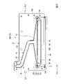
図1はプリンタ1の概略構成図である。
図1に示すように、本実施形態のプリンタ1は、一対の搬送機構2,3と、インク供給機構4と、インクジェットヘッド5A,5Bと、走査機構6と、を備えている。なお、以下の説明では、必要に応じてX,Y,Zの直交座標系を用いて説明する。この場合、X方向は被記録媒体P(例えば、紙等)の搬送方向(副走査方向)に一致している。Y方向は走査機構6の走査方向(主走査方向)に一致している。Z方向は、X方向及びY方向に直交する高さ方向(重力方向)を示している。以下の説明では、X方向、Y方向及びZ方向のうち、図中矢印方向をプラス(+)方向とし、矢印とは反対の方向をマイナス(-)方向として説明する。本実施形態において、+Z方向は重力方向の上方に相当し、-Z方向は重力方向の下方に相当する。[Printer]
FIG. 1 is a schematic configuration diagram of a
As shown in FIG. 1, the
搬送機構2,3は、被記録媒体Pを+X方向に搬送する。具体的に、搬送機構2は、Y方向に延設されたグリットローラ11と、グリットローラ11に平行に延設されたピンチローラ12と、グリットローラ11を軸回転させるモータ等の駆動機構(不図示)と、を備えている。同様に、搬送機構3は、Y方向に延設されたグリットローラ13と、グリットローラ13に平行に延設されたピンチローラ14と、グリットローラ13を軸回転させる駆動機構(不図示)と、を備えている。 The
インク供給機構4は、インクが収容されたインクタンク15と、インクタンク15とインクジェットヘッド5A,5Bとを接続するインク配管16と、を備えている。
本実施形態において、インクタンク15は、X方向に複数並べられている。各インクタンク15には、例えばイエロー、マゼンタ、シアン、ブラックの4色のインクが各別に収容されている。
インク配管16は、例えば可撓性を有するフレキシブルホースである。インク配管16は、各インクタンク15と各インクジェットヘッド5A,5Bとの間を接続している。The
In this embodiment, a plurality of
The
走査機構6は、インクジェットヘッド5A,5BをY方向に往復走査させる。具体的に、走査機構6は、Y方向に延設された一対のガイドレール21,22と、一対のガイドレール21,22に移動可能に支持されたキャリッジ23と、キャリッジ23をY方向に移動させる駆動機構24と、を備えている。 The
駆動機構24は、X方向におけるガイドレール21,22の間に配設されている。駆動機構24は、Y方向に間隔をあけて配設された一対のプーリ25,26と、一対のプーリ25,26間に巻回された無端ベルト27と、一方のプーリ25を回転駆動させる駆動モータ28と、を備えている。 The
キャリッジ23は、無端ベルト27に連結されている。キャリッジ23には、複数のインクジェットヘッド5A,5BがY方向に並んだ状態で搭載されている。各インクジェットヘッド5A,5Bは、1つのインクジェットヘッド5A,5Bにつき2色のインクを吐出可能に構成されている。したがって、本実施形態のプリンタ1では、各インクジェットヘッド5A,5Bそれぞれが互いに異なる2色のインクを吐出することで、イエロー、マゼンタ、シアン、ブラックの4色のインクを吐出可能に構成されている。 The
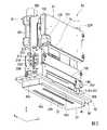
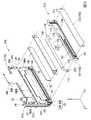
<インクジェットヘッド>
図2は、インクジェットヘッド5Aの斜視図である。図3は、インクジェットヘッド5Aにおいて、一部を分解した斜視図である。なお、インクジェットヘッド5A,5Bは、供給されるインクの色以外は何れも同等の構成である。そのため、以下の説明ではインクジェットヘッド5Aについて説明し、インクジェットヘッド5Bの説明を省略する。
図2、図3に示すように、本実施形態のインクジェットヘッド5Aは、ジェットモジュール30A,30B(図3参照)やダンパ31、ノズルプレート32(図2参照)、ノズルガード33等がベース部材38に搭載されて構成されている。<Inkjet head>
FIG. 2 is a perspective view of the
As shown in FIGS. 2 and 3, the
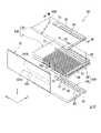
(ベース部材)
図4は、インクジェットヘッド5Aにおいて、ベース部材38と第1ジェットモジュール30Aの分解斜視図である。
図4に示すように、ベース部材38は、Z方向を厚さ方向とし、X方向を長手方向とする板状に形成されている。ベース部材38は、各ジェットモジュール30A,30Bを保持するベース本体部41と、ベース部材38をキャリッジ23(図1参照)に固定するためのキャリッジ固定部42と、を有している。なお、本実施形態において、ベース部材38は、金属材料により一体で形成されている。(Base member)
FIG. 4 is an exploded perspective view of the
As shown in FIG. 4, the
ベース本体部41には、モジュール収容部(第1モジュール収容部44A及び第2モジュール収容部44B)が形成されている。各モジュール収容部44A,44Bは、ジェットモジュール30A,30Bに対応してY方向に2つ並んで形成されている。各モジュール収容部44A,44Bは、ベース本体部41をZ方向に貫通している。各モジュール収容部44A,44Bには、対応するジェットモジュール30A,30Bがそれぞれ差込可能とされている。すなわち、ジェットモジュール30A,30Bは、-Z方向端部が各モジュール収容部44A,44B内に差し込まれることで、ベース部材38から+Z方向に起立した状態でベース本体部41に保持されている。 A module accommodating portion (first
ベース本体部41において、各モジュール収容部44A,44B間に位置する部分には、各モジュール収容部44A,44B間を仕切る仕切部46が形成されている。
ベース本体部41におけるX方向で対向する一対の短辺部45a,45bには、X方向の内側に向けて突出する突出壁47が形成されている。突出壁47は、X方向で対向する突出壁47同士を1組として、各モジュール収容部44A,44B毎に形成されている。In the base
A pair of
第1短辺部45aには第1付勢部材48が設けられている。第1付勢部材48は、各モジュール収容部44A,44Bに対応して設けられている。各第1付勢部材48は、第1短辺部45aと各ジェットモジュール30A,30Bとの間にそれぞれ介在する板ばね状に形成されている。各第1付勢部材48は、各ジェットモジュール30A,30Bを第2短辺部45bに向けて(-X方向)付勢する。 The first urging
キャリッジ固定部42は、ベース本体部41の+Z方向端部からXY平面に張り出している。キャリッジ固定部42には、ベース部材38をキャリッジ23(図1参照)に取り付けるための取付孔等が形成されている。 The
(ジェットモジュール)
図3に示すように、ジェットモジュール30A,30Bは、Y方向を厚さ方向とする板状に形成されている。ジェットモジュール30A,30Bは、インクタンク15(図1参照)から供給されるインクを被記録媒体Pに向けて吐出可能に構成されている。ジェットモジュール30A,30Bは、ベース部材38上にY方向に間隔をあけて搭載されている。(Jet module)
As shown in FIG. 3, the
本実施形態のインクジェットヘッド5Aでは、ジェットモジュール30A,30Bのうち、各ジェットモジュールで1色ずつインクを吐出するようになっている。なお、ベース部材38に搭載されるジェットモジュール30A,30Bの数や、ジェットモジュール30A,30Bから吐出するインクの色、種類等は、適宜変更が可能である。各ジェットモジュール30A,30Bは、同一の構成からなるジェットモジュール同士がY方向で互いに逆向きでベース部材38に搭載されている。したがって、以下の構成では、第1ジェットモジュール30Aを例にして説明する。 In the
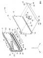
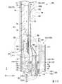
図5は、第1ジェットモジュール30Aの分解斜視図である。
図5に示すように、第1ジェットモジュール30Aは、吐出部50と、吐出部50を間に挟んでY方向で対向する第1流路部材51A及び第2流路部材51Bと、を主に備えている。FIG. 5 is an exploded perspective view of the
As shown in FIG. 5, the
(吐出部)
図6は、吐出部50の分解斜視図である。
図6に示すように、吐出部50は、第1ヘッドチップ52Aと、第1ヘッドチップ52Aに対して+Y方向に積層された第2ヘッドチップ52Bと、を有している。各ヘッドチップ52A,52Bは、後述する吐出チャネル57における延在方向(Z方向)の端部からインクを吐出する、いわゆるエッジシュートタイプのものである。(Discharge part)
FIG. 6 is an exploded perspective view of the
As shown in FIG. 6, the
第1ヘッドチップ52Aは、第1アクチュエータプレート55及び第1カバープレート56がY方向に重ね合わされて構成されている。 The
第1アクチュエータプレート55は、PZT(チタン酸ジルコン酸鉛)等により形成された圧電基板である。第1アクチュエータプレート55は、分極方向が厚さ方向(Y方向)に沿って一方向に設定されている。なお、第1アクチュエータプレート55は、分極方向がY方向で異なる2枚の圧電基板を積層して形成しても構わない(いわゆる、シェブロンタイプ)。 The
第1アクチュエータプレート55には、-Y方向を向く面(以下、「表面」という。)で開口する複数のチャネル57,58が、X方向に間隔をあけて並設されている。各チャネル57,58は、それぞれZ方向に沿って直線状に形成されている。各チャネル57,58は、第1アクチュエータプレート55における-Z方向端面上で開口している。なお、各チャネル57,58は、Z方向に対して傾いて延在していても構わない。 On the
図7は、図6のVII-VII線に沿う断面図である。
図6、図7に示すように、上述した複数のチャネル57,58は、インクが充填される吐出チャネル57、及びインクが充填されない非吐出チャネル58である。吐出チャネル57及び非吐出チャネル58は、X方向に交互に並んで配置されている。各チャネル57,58は、第1アクチュエータプレート55からなる駆動壁61によってそれぞれX方向に仕切られている。なお、チャネル57,58の内面には、駆動電極59が形成されている。駆動電極59は、第1アクチュエータプレート55の+Z方向端部において、第1アクチュエータプレート55の表面に形成された駆動端子(不図示)に接続されている。FIG. 7 is a cross-sectional view taken along the line VII-VII of FIG.
As shown in FIGS. 6 and 7, the plurality of
第1カバープレート56は、Y方向から見た平面視で矩形状に形成されている。第1カバープレート56は、第1アクチュエータプレート55の+Z方向端部を突出させた状態で、第1アクチュエータプレート55の表面に接合されている(図10参照)。 The
第1カバープレート56は、-Y方向を向く面(以下、「表面」という。)で開口する共通インク室62と、+Y方向を向く面(以下、「裏面」という。)で開口する複数のスリット63と、を有している。
共通インク室62は、Z方向において、吐出チャネル57の+Z方向端部に対応する位置に形成されている。共通インク室62は、第1カバープレート56の表面から+Y方向に向けて窪むとともに、X方向に延設されている。共通インク室62には、上述した第1流路部材51Aを通してインクが流入する。
スリット63は、共通インク室62のうち、吐出チャネル57とY方向で対向する位置に形成されている。スリット63は、共通インク室62内と各吐出チャネル57内とを各別に連通している。したがって、非吐出チャネル58は、共通インク室62内には連通していない。The
The
The
第1カバープレート56のうち、共通インク室62よりもX方向の外側に位置する部分には、一対の第1気泡抜き孔65Aが形成されている。各第1気泡抜き孔65Aは、第1カバープレート56をY方向に貫通した後、第1カバープレート56と第1アクチュエータプレート55との間を-Z方向に延在している。すなわち、第1気泡抜き孔65Aのうち、第1開口部は第1カバープレート56の表面で開口し、第2開口部は第1ヘッドチップ52Aの-Z方向端面で開口している。 A pair of first bubble vent holes 65A are formed in a portion of the
第2ヘッドチップ52Bは、第2アクチュエータプレート71及び第2カバープレート72がY方向に重ね合わされて構成されている。以下の説明では、第2ヘッドチップ52Bにおける第1ヘッドチップ52Aと同様の構成について、第1ヘッドチップ52Aと同一の符号を付して説明を省略する。 The
第2アクチュエータプレート71は、第1アクチュエータプレート55のうち、+Y方向を向く面(以下、「裏面」という。)に接合されている。第2ヘッドチップ52Bの吐出チャネル57及び非吐出チャネル58は、第1ヘッドチップ52Aの吐出チャネル57及び非吐出チャネル58の配列ピッチに対して半ピッチずれて配列されている。すなわち、各ヘッドチップ52A,52Bの吐出チャネル57同士及び非吐出チャネル58同士は、それぞれ千鳥状に配列されている。 The
第2カバープレート72は、第2アクチュエータプレート71における+Y方向を向く面(以下、「表面」という。)に接合されている。第2カバープレート72のうち、共通インク室62よりも少なくとも+X方向に位置する部分には、第2気泡抜き孔65Bが形成されている。第2気泡抜き孔65Bは、第2カバープレート72をY方向に貫通した後、第2カバープレート72と第2アクチュエータプレート71との間を-Z方向に延在している。 The
吐出部50において、チャネル57,58が配列された領域を吐出領域Q1とし、吐出領域Q1に対してX方向の両側に位置する領域(最外のチャネル57,58よりも外側の領域)を一対の非吐出領域Q2とする。非吐出領域Q2には、吐出部50(各ヘッドチップ52A,52B)をY方向に貫通する連通孔73(図6,7では、一方の連通孔73のみを示す)が形成されている。連通孔73は、各ヘッドチップ52A,52B(アクチュエータプレート55,71及びカバープレート56,72)をY方向に貫通し、各ヘッドチップ52A,52Bの共通インク室62同士を連通させている。なお、連通孔73の数や位置、形状等は適宜変更が可能である。 In the
(第1流路部材)
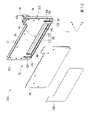
図8は、第1流路部材51Aにおいて、第1流路板77から+Y方向に展開させた分解斜視図である。
図8に示すように、第1流路部材51Aは、第1マニホールド75と、流入ポート76と、を有している。なお、第1マニホールド75及び流入ポート76は、一体に形成されていても構わない。
第1マニホールド75は、全体としてY方向を厚さ方向とする板状に形成されている。図3に示すように、第1マニホールド75は、-Z方向端部が上述した第1モジュール収容部44A内に差し込まれることで、+Z方向に起立した状態でベース部材38に保持されている。(First flow path member)
FIG. 8 is an exploded perspective view of the first
As shown in FIG. 8, the first
The
図8に示すように、第1マニホールド75は、第1流路板77と、第1流路板77に対して+Y方向に配設されたフロントカバー78と、第1流路板77に対して-Y方向に配設されたリアカバー79と、を有している。 As shown in FIG. 8, the
第1流路板77は、熱伝導性に優れた材料により形成されている。本実施形態において、第1流路板77の材料には、金属材料(例えば、アルミニウム等)が好適に用いられている。第1流路板77には、第1ヘッドチップ52Aに向けてインクが流通する第1インク流路81が形成されている。 The first
図9は、第1流路板77を+Y方向から見た正面図である。
図8、図9に示すように、第1インク流路81は、上流流路83、濾過流路84、下流流路85及び供給流路86(図11参照)が連なって形成されている。
上流流路83は、第1流路板77において+Y方向に開口している。具体的に、上流流路83は、幅狭流路91と、幅狭流路91及び濾過流路84間を接続する接続流路92と、を有している。FIG. 9 is a front view of the first
As shown in FIGS. 8 and 9, the first
The
幅狭流路91は、第1流路板77における+X方向、かつ+Z方向に位置する部分を上流端とし、第1流路板77におけるZ方向及びX方向の中央部に位置する部分を下流端として、上流端から下流端に向かうに従い屈曲しながら延在している。具体的に、幅狭流路91は、上流端から-Z方向に延在した後、-Z方向に向かうに従い-X方向に延在し、さらに-Z方向に延在している。本実施形態において、幅狭流路91の流路幅(流通方向及びY方向に直交する方向での幅)、及び流路深さ(Y方向での深さ)は、全体に亘って一様に設定されている。但し、幅狭流路91の形状や流路幅、流路深さは、適宜変更が可能である。 In the
図9に示すように、接続流路92は、+Y方向から見た正面視において、-Z方向に向かうに従い流路幅が漸次拡幅する三角形状に形成されている。接続流路92は、+Z方向端部において、幅狭流路91の下流端に連通している。本実施形態において、接続流路92の上流端(+Z方向端部)での流路幅は、幅狭流路91の下流端での流路幅と同等になっている。 As shown in FIG. 9, the connecting
図10は、図8のX-X線に相当する第1ジェットモジュール30Aの断面図である。
図10に示すように、接続流路92は、+X方向から見た断面視において、-Z方向に向かうに従い流路深さが漸次浅くなっている。すなわち、本実施形態の接続流路92は、上流側から下流側に向かうに従い流路幅が広くなる一方、上流側から下流側に向かうに従い流路深さが浅くなっている。本実施形態において、接続流路92の上流端での流路深さは、幅狭流路91の下流端での流路深さと同等になっている。FIG. 10 is a cross-sectional view of the
As shown in FIG. 10, the depth of the connecting
接続流路92における下流端(-Z方向端部)での流路断面積(XY平面での断面積)は、上流端での流路断面積よりも小さくなっていることが好ましい。但し、接続流路92の流路幅や流路深さ、流路断面積は、適宜変更が可能である。
なお、本実施形態では、流路幅及び流路深さが連続的(直線状)に変化する構成について説明したが、この構成のみに限られない。すなわち、接続流路92は、流路幅及び流路深さが下流側に向かうに従い徐々に変化する構成であれば、例えば階段状や曲線状に形成されていても構わない。また、傾きの異なる複数の直線が連なる構成であっても構わない。It is preferable that the flow path cross-sectional area (cross-sectional area in the XY plane) at the downstream end (end in the −Z direction) of the connecting
In the present embodiment, the configuration in which the channel width and the channel depth change continuously (linearly) has been described, but the configuration is not limited to this configuration. That is, the connecting
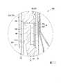
図11は、図10のXI部拡大図である。
図9、図11に示すように、濾過流路84は、接続流路92における下流端とZ方向で連通するとともに、接続流路92から流入するインクを-Y方向に向けて流通させる。具体的に、濾過流路84は、+Y方向に位置するフィルタ入口流路95と、フィルタ入口流路95に対して-Y方向に連なるフィルタ出口流路96と、を有している。
フィルタ入口流路95は、+Z方向端部(重力方向の上端部)において、接続流路92に連通している。フィルタ入口流路95におけるX方向での幅は、接続流路92における下流端でのX方向の幅と同等になっている。FIG. 11 is an enlarged view of the XI portion of FIG.
As shown in FIGS. 9 and 11, the
The filter
フィルタ出口流路96は、Y方向から見た正面視での面積(流路断面積)がフィルタ入口流路95に比べて一回り小さくなっている。すなわち、フィルタ入口流路95とフィルタ出口流路96との境界部分には、+Y方向を向く段差面97が形成されている。段差面97は、フィルタ入口流路95の外周縁に倣って延びる額縁状に形成されている。 The area (flow path cross-sectional area) of the filter
フィルタ入口流路95には、濾過流路84をフィルタ入口流路95とフィルタ出口流路96とにY方向で仕切るメインフィルタ99が配置されている。メインフィルタ99は、Y方向から見た平面視外形がフィルタ入口流路95と同等の大きさに形成されたメッシュシートである。メインフィルタ99は、外周部分が上述した段差面97に+Y方向から接合されている。インクは、フィルタ入口流路95からフィルタ出口流路96に流通する過程でメインフィルタ99を通過する。これにより、インク中に含まれる異物や気泡がメインフィルタ99により捕捉される。 In the filter
図11に示すように、フィルタ出口流路96の内面には、フィルタ出口流路96と下流流路85との間をY方向で仕切る貯留壁部100が形成されている。貯留壁部100は、フィルタ出口流路96の内面のうち、-Z方向(重力方向の下方)に位置する-Z方向内側面から+Z方向に立設されるとともに、フィルタ出口流路96におけるX方向の全体に亘って形成されている。 As shown in FIG. 11, a
貯留壁部100における+Z方向端部には、貯留壁部100をY方向に貫通する連通流路102が形成されている。連通流路102は、貯留壁部100(フィルタ出口流路96)におけるX方向の全体に亘って連続的に形成されている。本実施形態において、連通流路102の内面のうち、+Z方向に位置する+Z方向内側面は、フィルタ出口流路96の内面のうち、+Z方向に位置する+Z方向内側面と面一になっている。すなわち、連通流路102は、フィルタ出口流路96の最上端部で開口している。但し、連通流路102及びフィルタ出口流路96における+Z方向内側面同士は、面一である場合に限られない。 A
連通流路102の上流端での流路断面積(XZ平面での面積)は、上述したフィルタ入口流路95の最小流路断面積(XY平面での断面積)よりも小さくなっていることが好ましい。但し、連通流路102の流路断面積は、フィルタ入口流路95の最小流路断面積と同等以上であっても構わない。なお、本実施形態では、フィルタ入口流路95の最小流路断面積を、フィルタ入口流路95の上流端(接続流路92との境界部分)に設定した場合について説明したが、この構成のみに限られない。すなわち、フィルタ入口流路95の最小流路断面積は、フィルタ入口流路95の任意の位置に設定することが可能である。 The flow path cross-sectional area (area in the XZ plane) at the upstream end of the
図12は、第1流路部材51Aにおいて、第1流路板77から-Y方向に展開させた分解斜視図である。
図10、図12に示すように、下流流路85は、第1流路板77において-Y方向に開口している。具体的に、下流流路85は、ストレート部110と、ストレート部110の下流側に連なる拡大部111と、を有している。FIG. 12 is an exploded perspective view of the first
As shown in FIGS. 10 and 12, the
ストレート部110は、貯留壁部100を間に挟んでフィルタ出口流路96にY方向で対向している。ストレート部110は、X方向における流路幅がフィルタ出口流路96と同等に形成されるとともに、Y方向での流路深さがZ方向の全体に亘って一様に形成されている。ストレート部110は、+Z方向の端部において、連通流路102を通じてフィルタ出口流路96に連通している。なお、ストレート部110の流路幅や流路深さは、適宜変更が可能である。 The
拡大部111は、ストレート部110の-Z方向端部から-Z方向に延在している。拡大部111は、X方向での流路幅がストレート部110と同等に形成されている。拡大部111は、Y方向での流路深さが-Z方向に向かうに従い漸次深くなっている。すなわち、拡大部111の流路断面積(Z方向に直交する方向での断面積)は、下流側(-Z方向)に向かうに従い漸次拡大している。 The
供給流路86は、第1流路板77の-Z方向端部において、第1流路板77をY方向に貫通している。供給流路86におけるX方向での流路幅は、拡大部111よりも広くなっている。本実施形態において、供給流路86の流路幅は、共通インク室62と同等に設定されている。 The
供給流路86における上流端(-Y方向端部)は、拡大部111の下流端(-Z方向端部)に連通している。一方、供給流路86における下流端は、第1流路板77において+Y方向に開口している。 The upstream end (-Y direction end) of the
図9に示すように、第1流路板77には、第1インク流路81に連通する第1気泡排出流路120が形成されている。第1気泡排出流路120は、濾過流路84に対してX方向の両側に一対で形成されている。すなわち、各第1気泡排出流路120は、第1流路部材51AにおけるX方向の中心を通り、Z方向に延びる対称軸に対して線対称に形成されている。そのため、以下の説明では、第1インク流路81に対して+X方向に位置する第1気泡排出流路120について説明する。なお、第1気泡排出流路120は、一対に限られない。 As shown in FIG. 9, the first
図9、図12に示すように、第1気泡排出流路120は、誘導部121と、第1貫通部122と、排出部123と、第2貫通部124と、を有している。
誘導部121は、第1流路板77において+Y方向に開口している。誘導部121は、上述した接続流路92及びフィルタ入口流路95に対して+X方向に連なっている。具体的に、誘導部121は、+X方向に向かうに従いZ方向の幅が漸次縮小するテーパ状に形成されている。具体的に、誘導部121の内面のうち、+Z方向に位置する+Z方向内側面は、X方向に沿って直線状に延在している。但し、+Z方向内側面は、+X方向に向かうに従い+Z方向や-Z方向に向けて傾斜して延在しても構わない。As shown in FIGS. 9 and 12, the first bubble
The
誘導部121の内面のうち、-Z方向に位置する-Z方向内側面は、+X方向に向かうに従い+Z方向に延びる傾斜面に形成されている。なお、誘導部121におけるY方向での深さは、誘導部121の全体に亘って一様になっている。但し、誘導部121の深さは、例えば+X方向に向かうに従い徐々に浅くなっていても構わない。 Of the inner surface of the
第1貫通部122は、誘導部121の頂部(+Z方向内側面と-Z方向内側面との交差部分)において、誘導部121に連通している。第1貫通部122は、第1流路板77をY方向に貫通している。本実施形態において、第1貫通部122は、濾過流路84よりも+Z方向であって、+X方向に配置されている。なお、第1貫通部122は、濾過流路84よりも+Z方向に配置されるか、濾過流路84よりも+X方向に配置されるかの何れか一方を満たしていることが好ましい。但し、第1貫通部122のZ方向及びX方向での位置は適宜変更が可能である。 The first penetrating
図12に示すように、排出部123は、第1流路板77において、-Y方向に開口している。排出部123は、Z方向に延在している。排出部123における+Z方向端部は、上述した第1貫通部122に連通している。 As shown in FIG. 12, the
第2貫通部124は、排出部123の-Z方向端部に連通している。第2貫通部124は、第1流路板77をY方向に貫通している。第2貫通部124と排出部123との境界部分には、サブフィルタ126が配置されている。 The second penetrating
リアカバー79は、Y方向から見た正面視で第1流路板77と同等の外形を有し、かつY方向の厚さが第1流路板77よりも薄い矩形板状に形成されている。リアカバー79は、第1流路板77のうち-Y方向を向く面に固定されている。すなわち、リアカバー79は、第1インク流路81(下流流路85や供給流路86)及び第1気泡排出流路120(貫通部122,124や排出部123)を-Y方向から閉塞している。なお、本実施形態において、リアカバー79は、熱伝導性に優れた金属材料(例えば、ステンレス等)により形成されている。 The
リアカバー79における-Y方向を向く面には、ヒータ130が配置されている。ヒータ130は、リアカバー79を通じて第1インク流路81内を加熱することで、第1インク流路81内を流通するインクを所定の温度範囲内に保持(保温)する。 A
図8に示すように、フロントカバー78は、リアカバー79と同形同大に形成された矩形板状のものである。すなわち、フロントカバー78は、Y方向の厚さが第1流路板77よりも薄くなっている。フロントカバー78は、第1流路板77のうち、+Y方向を向く面に固定されている。すなわち、フロントカバー78は、第1インク流路81(上流流路83や濾過流路84)及び第1気泡排出流路120(誘導部121や貫通部122)を+Y方向から閉塞している。 As shown in FIG. 8, the
フロントカバー78のうち、Y方向から見て供給流路86と重なり合う位置には、供給流路86を開放させる連通口132が形成されている。連通口132は、Y方向から見た正面視で供給流路86と同等の形状をなし、フロントカバー78をY方向に貫通している。
フロントカバー78のうち、Y方向から見て上流流路83の上流端(+Z方向端部)と重なり合う位置には、上流流路83を開放させる流入口133が形成されている。流入口133は、フロントカバー78をY方向に貫通している。A
An
フロントカバー78のうち、Y方向から見て第2貫通部124と重なり合う位置には、第2貫通部124を開放させる排出口134が形成されている。排出口134は、フロントカバー78をY方向に貫通している。 A
本実施形態では、第1流路板77のみに溝状の第1インク流路81を形成した場合について説明したが、この構成のみに限らず、第1流路板77、フロントカバー78及びリアカバー79のうち少なくとも何れか一方にインク流路が形成されていれば構わない。この場合、例えば第1流路板77やフロントカバー78、リアカバー79のそれぞれに溝部を形成し、これら溝部を重ね合わせてインク流路としても構わない。 In the present embodiment, the case where the groove-shaped first
流入ポート76は、Z方向に延びる筒状に形成されている。流入ポート76は、フロントカバー78における+Z方向端部に固定されている。流入ポート76内は、上述した流入口133を通じて第1インク流路81内に連通している。 The
(第1絶縁シート)
図8に示すように、フロントカバー78における+Y方向を向く面には、第1絶縁シート135が設けられている。第1絶縁シート135は、Y方向から見た正面視で-Z方向に開口するU字状に形成されている。第1絶縁シート135は、フロントカバー78において連通口132の周囲を取り囲んでいる。具体的に、第1絶縁シート135は、連通口132に対してX方向の両側に位置する一対の外側台座部136と、外側台座部136の+Z方向端部同士を接続するブリッジ部137と、を有している。なお、本実施形態において、第1絶縁シート135は、例えばポリイミドが好適に用いられている。但し、第1絶縁シート135の材料は、絶縁性や耐インク性(耐溶出性)を有し、かつ比較的軟質な材料(例えば、樹脂材料やゴム材料)により形成されていれば適宜変更が可能である。(1st insulation sheet)
As shown in FIG. 8, the first insulating
外側台座部136において、Y方向から見て上述した排出口134と重なり合う位置には、排出口134を露出させる露出口140が形成されている。露出口140は、外側台座部136をY方向に貫通している。
外側台座部136において、露出口140よりも+Z方向に位置する部分には、外側台座部136をY方向に貫通する位置決め孔142が形成されている。位置決め孔142は、第1流路部材51Aから+Y方向に突出する係合ピン143を収容している。なお、位置決め孔142は、ブリッジ部137に形成しても構わない。An exposed
In the
ブリッジ部137は、連通口132に対して+Z方向に位置している。すなわち、フロントカバー78において、連通口132に対して-Z方向に位置する部分は、第1絶縁シート135が位置していないブランク領域141になっている。なお、第1絶縁シート135は、少なくとも非吐出領域Q2に外側台座部136のみを有していれば構わない。 The
図10に示すように、上述した第1ヘッドチップ52Aは、第1カバープレート56の表面を-Y方向に向けた状態でフロントカバー78や第1絶縁シート135に固定されている。具体的に、第1カバープレート56の表面のうち、第1絶縁シート135に対向する部分は、接着剤S1を介して第1絶縁シート135に固定されている。一方、第1カバープレート56の表面のうち、ブランク領域141に対向する部分は、接着剤S1を介してフロントカバー78に直接固定されている。 As shown in FIG. 10, the above-mentioned
第1ヘッドチップ52Aが第1流路部材51Aに固定された状態において、駆動壁61(図6に示す吐出領域Q1)はブランク領域141にY方向で対向する。すなわち、本実施形態において、駆動壁61とフロントカバー78との間には、接着剤S1のみが介在する(第1絶縁シート135が介在しない)ようになっている。この場合、接着剤S1は、共通インク室62及び連通口132の周囲を取り囲み、第1ヘッドチップ52Aと第1流路部材51Aとの間をシールしている。なお、本実施形態で用いる接着剤S1は、絶縁性を有し、かつ比較的軟質(第1絶縁シート135よりも軟質)な材料(例えば、シリコーン系)等が用いられている。 In a state where the
第1ヘッドチップ52Aが第1流路部材51Aに固定された状態において、第1カバープレート56の共通インク室62は、連通口132を通じて供給流路86に連通する。一方、図8に示すように、第1ヘッドチップ52Aの第1気泡抜き孔65A(図7参照)は、露出口140及び排出口134を通じて第1気泡排出流路120(第2貫通部124)に連通する。 In a state where the
(第2流路部材)
図5に示すように、第2流路部材51Bは、第2マニホールド150と、第2付勢部材151と、を有している。
第2マニホールド150は、全体としてY方向を厚さ方向とし、Z方向の長さが第1マニホールド75よりも短い板状に形成されている。図3に示すように、第2マニホールド150は、-Z方向端部が上述した第1モジュール収容部44A内に差し込まれることで、+Z方向に起立した状態でベース部材38に保持されている。(Second flow path member)
As shown in FIG. 5, the second
The
図5に示すように、第2マニホールド150は、第2流路板152と、流路カバー153と、を有している。
第2流路板152は、第1流路板77と同様に、金属材料(例えば、アルミニウム等)等により形成されている。第2流路板152には、第2ヘッドチップ52Bに向けてインクが流通する第2インク流路155が形成されている。As shown in FIG. 5, the
Like the first
図13は、第2流路板152を+Y方向から見た正面図である。
図13に示すように、第2インク流路155は、第2流路板152をY方向に貫通するとともに、X方向に帯状に延在している。第2インク流路155は、Y方向から見た正面視外形が共通インク室62と同等の形状に形成されている。したがって、吐出部50の連通孔73は、第2インク流路155におけるX方向の両端部において、第2インク流路155にY方向で対向している。なお、本実施形態において、第2インク流路155及び第2ヘッドチップ52Bの共通インク室62の合計容積は、上述した供給流路86及び第1ヘッドチップ52Aの共通インク室62の合計容積と同等に設定されていることが好ましい。FIG. 13 is a front view of the second
As shown in FIG. 13, the second
図13における符号157は、第2インク流路155に連通する洗浄流路である。洗浄流路157には、メンテナンス時等において、後述するノズル孔240から吸い上げられ、吐出部50や第2インク流路155等を通過した洗浄液が流入する。洗浄流路157に流入した洗浄液は、洗浄ポート158を通じて吸引される。
第2流路板152には、第2インク流路155に連通する第2気泡排出流路160が形成されている。第2気泡排出流路160は、排出部161と、貫通部162と、を有している。
排出部161は、第2流路板152において+Y方向に開口している。排出部161は、第2流路板152のうち、第2インク流路155に対して+Z方向に位置する部分をX方向に延在している。排出部161の上流端は、第2インク流路155の内面における+Z方向(重力方向の上方)に位置する+Z方向内側面のうち、X方向の中央部で開口している。すなわち、上述した一対の連通孔73と排出部161の上流端とのX方向での距離は、それぞれ同等に設定されている。なお、一対の連通孔73と排出部161の上流端とのX方向での距離は、適宜変更が可能である。また、連通孔73の数や位置は、適宜変更が可能である。The second
The
排出部161の下流端は、第2インク流路155に対して+X方向に位置する部分で貫通部162に連通している。なお、本実施形態では、第2インク流路155に対して+Z方向に第2気泡排出流路160が配置される構成について説明したが、この構成のみに限られない。 The downstream end of the
貫通部162は、第2流路板152をY方向に貫通している。貫通部162内には、サブフィルタ165が配置されている。 The penetrating
第2流路板152において、第2気泡排出流路160の+Z方向に位置する部分には、センサ収容部167が形成されている。センサ収容部167は、第2流路板152において+Y方向に開口するとともに、X方向に延在している。 In the second
図5に示すように、流路カバー153は、Y方向から見た正面視で第2流路板152と同等の外形を有し、かつY方向の厚さが第2流路板152よりも薄い矩形板状に形成されている。流路カバー153は、第2インク流路155、第2気泡排出流路160及びセンサ収容部167を+Y方向から閉塞している。なお、流路カバー153は、熱伝導性に優れた金属材料(例えば、ステンレス等)により形成されている。 As shown in FIG. 5, the flow path cover 153 has an outer shape equivalent to that of the second
第2付勢部材151は、第2流路板152におけるX方向の両端部に一対で設けられている。各第2付勢部材151は、第2流路板152に対して+Y方向に自由端が配置された板ばね状とされている。図3に示すように、第2付勢部材151は、第2流路部材51Bが第1モジュール収容部44Aに差し込まれた状態において、ベース本体部41におけるY方向で対向する長辺部45c,45dのうち、第1長辺部45cと第2マニホールド150との間に介在する。すなわち、第2付勢部材151は、ジェットモジュール30Aを-Y方向に向けて付勢する。 The
(第2絶縁シート)
図5に示すように、第2流路板152における-Y方向を向く面には、第2絶縁シート170が設けられている。第2絶縁シート170は、上述した第1絶縁シート135と同様に、外側台座部171及びブリッジ部172有している。(2nd insulation sheet)
As shown in FIG. 5, a second insulating
各外側台座部171のうち、+X方向に位置する外側台座部171において、Y方向から見て貫通部162と重なり合う位置には、貫通部162を露出させる露出口175が形成されている。露出口175は、外側台座部171をY方向に貫通している。 In each
ブリッジ部172は、第2インク流路155に対して+Z方向に位置している。すなわち、第2流路板152において、第2インク流路155に対して-Z方向に位置する部分は、第2絶縁シート170が位置していないブランク領域178(図10参照)になっている。
ブリッジ部172において、X方向の両端部には、ブリッジ部172をY方向に貫通する位置決め孔173が形成されている。位置決め孔173は、第2流路部材51Bから-Y方向に突出する係合ピン(不図示)を収容している。なお、位置決め孔173は、外側台座部171に形成しても構わない。The
In the
図10に示すように、上述した第2ヘッドチップ52Bは、第2カバープレート72の表面を+Y方向に向けた状態で第2流路板152や第2絶縁シート170に固定されている。具体的に、第2カバープレート72の表面のうち、第2絶縁シート170に対向する部分は、接着剤S2を介して第2絶縁シート170に固定されている。一方、第2カバープレート72の表面のうち、ブランク領域178に対向する部分は、接着剤S2を介して第2流路板152に直接固定されている。第2ヘッドチップ52Bが第2流路部材51Bに固定された状態において、駆動壁61(図6に示す吐出領域Q1)はブランク領域178にY方向で対向する。この場合、接着剤S2は、共通インク室62及び第2インク流路155の周囲を取り囲み、第2ヘッドチップ52Bと第2流路部材51Bとの間をシールしている。なお、接着剤S1,S2には、同様の材料が用いられている。 As shown in FIG. 10, the above-mentioned
本実施形態では、各ヘッドチップ52A,52Bと流路部材51A,51Bとの間に絶縁シート135,170を各別に介在させる構成について説明したが、少なくとも第1ヘッドチップ52Aと第1流路部材51Aとの間に第1絶縁シート135が介在していれば構わない。 In the present embodiment, the configuration in which the insulating
第2ヘッドチップ52Bが第2流路部材51Bに固定された状態において、第2カバープレート72の共通インク室62は、第2インク流路155に連通する。第2ヘッドチップ52Bの第2気泡抜き孔65Bは、露出口175を通じて第2気泡排出流路160(貫通部162)に連通する。 In a state where the
このように、本実施形態のジェットモジュール30Aは、第1流路部材51A及び第2流路部材51BがY方向で対向するとともに、各流路部材51A,51B間に2つのヘッドチップ52A,52Bを有する吐出部50が挟持されている。 As described above, in the
(FPCユニット)
図5に示すように、第1マニホールド75のフロントカバー78には、FPCユニット180が支持されている。FPCユニット180は、駆動基板181及び配線基板182を備えている。駆動基板181及び配線基板182は、それぞれフレキシブルプリント基板であって、ベースフィルムに配線パターンが形成されて構成されている。(FPC unit)
As shown in FIG. 5, the
駆動基板181は、実装部185、チップ接続部186、センサ接続部187及び引出部188を有している。なお、駆動基板181は、実装部185にリジッド基板等を用いても構わない。 The
実装部185は、フロントカバー78に支持されている。実装部185には、例えば複数のドライバ190A,190Bが実装されている。ドライバ190A,190Bは、第1ヘッドチップ52Aを駆動する第1ドライバ190A、及び第2ヘッドチップ52Bを駆動する第2ドライバ190Bである。各ドライバ190A,190Bは、X方向に直線状に並んでいる。なお、本実施形態では、1枚の駆動基板181に第1ドライバ190A及び第2ドライバ190Bがまとめて実装された構成について説明するが、この構成のみに限らず、各ドライバに対応して駆動基板を設けても構わない。 The mounting
図10に示すように、チップ接続部186は、実装部185から-Z方向に延設されている。チップ接続部186の-Z方向端部は、第1アクチュエータプレート55の+Z方向端部に圧着等により固定されている。これにより、第1ドライバ190Aと、第1ヘッドチップ52Aの駆動電極59と、がチップ接続部186を介して電気的に接続される。 As shown in FIG. 10, the
図5、図13に示すように、センサ接続部187は、実装部185から+X方向に延設されている。センサ接続部187の先端部には、温度センサ191(例えば、サーミスタ等)が実装されている。センサ接続部187は、上述したセンサ収容部167内に収容されている。すなわち、温度センサ191は、第2流路板152を介して吐出部50のインク温度を検出する。 As shown in FIGS. 5 and 13, the
引出部188は、実装部185から+Z方向に延設されている。引出部188は、インターフェイス192(図3参照)に接続されている。インターフェイス192は、例えばインクジェットヘッド5Aの外部から供給される電力をFPCユニット180に電力を供給したり、制御信号の送受信を行ったりするためのものである。 The
図5、図10に示すように、配線基板182は、実装部185と第2ヘッドチップ52Bとの間を接続している。具体的に、配線基板182のうち、+Z方向端部が実装部185に接続され、-Z方向端部が第2アクチュエータプレート71の+Z方向端部に圧着等により固定されている。これにより、第2ドライバ190Bと、第2ヘッドチップ52Bの駆動電極59と、が配線基板182を介して電気的に接続される。 As shown in FIGS. 5 and 10, the
図3、図5に示すように、第1流路部材51Aのうち、Y方向から見て上述したドライバ190A,190Bと重なり合う位置には、放熱板195が配置されている。放熱板195は、駆動基板181をX方向に跨るように形成されている。放熱板195は、伝熱シート196を間に挟んでドライバ190A,190Bを覆っている。放熱板195のX方向の両端部は、駆動基板181よりも外側において第1流路部材51Aに固定されている。なお、放熱板195及び伝熱シート196は、熱伝導性に優れた材料により形成されている。本実施形態において、放熱板195は例えばアルミニウム等により形成され、伝熱シート196は例えばシリコーン樹脂等により形成されている。 As shown in FIGS. 3 and 5, the
図3、図4に示すように、上述した第1ジェットモジュール30Aは、第1流路部材51Aが-Y方向を向き、第2流路部材51Bが+Y方向を向いた状態で、第1モジュール収容部44A内に差し込まれている。この際、第1ジェットモジュール30Aは、第2流路部材51Bと第1短辺部45aとの間に第1付勢部材48が介在し、第2流路部材51Bと第1長辺部45cとの間に第2付勢部材151が介在した状態でベース部材38に保持されている。そのため、第1ジェットモジュール30Aは、第1付勢部材48によって-X方向(第2短辺部45bに向かう方向)に付勢され、第2付勢部材151によって-Y方向(仕切部46に向かう方向)に付勢された状態でベース部材38に保持されている。この際、吐出部50の-Z方向端面は、ベース部材38(ベース本体部41)の-Z方向端面と面一に配置されるか、ベース部材38の-Z方向端面よりも-Z方向に配置されることが好ましい。 As shown in FIGS. 3 and 4, the above-mentioned
第2ジェットモジュール30Bは、第1流路部材51Aが+Y方向を向き、第2流路部材51Bが-Y方向を向いた状態で、第2モジュール収容部44B内に差し込まれている。すなわち、第2ジェットモジュール30Bの第1流路部材51Aは、第1ジェットモジュール30Aの第1流路部材51AにY方向で対向している。なお、各ジェットモジュール30A,30Bは、対応するモジュール収容部44A,44Bに接着剤により固定される。 The
(ステーユニット)
図2に示すように、ベース部材38には、ベース部材38への搭載部品を支持するステーユニット200が設けられている。ステーユニット200は、ベース部材38から+Z方向に起立するとともに、各ジェットモジュール30A,30Bの周囲をまとめて取り囲んでいる。(Stay unit)
As shown in FIG. 2, the
ステーユニット200のうち、X方向の両側に位置するX方向ステー(第1ステー201及び第2ステー202)と、ジェットモジュール30A,30Bと、の間にはモジュール保持機構210が介在している。なお、各モジュール保持機構210は何れも同様の構成からなるため、以下の説明では、第1ステー201と第1ジェットモジュール30Aとの間に介在するモジュール保持機構210を例にして説明する。 In the
第1ステー201は、ジェットモジュール30A,30Bに対して+X方向に位置している。第1ステー201は、-Z方向端部がモジュール収容部44A,44B内に差し込まれた状態で、ベース部材38から+Z方向に起立している。なお、第1ステー201は、ベース部材38へのジェットモジュール30A,30Bの組付後にベース部材38に組み付けられる。 The
図14は、図2のXIV-XIV線に沿う部分断面図である。
図3、図14に示すように、モジュール保持機構210は、第1流路部材51Aに設けられた位置決めピン212と、第1ステー201に形成された第1収容部214と、位置決めピン212と第1ステー201との間を連結するサポート片216と、を有している。FIG. 14 is a partial cross-sectional view taken along the line XIV-XIV of FIG.
As shown in FIGS. 3 and 14, the
位置決めピン212は、第1流路板77から+X方向に突出している。なお、位置決めピン212は、ベース部材38に対してZ方向に離間した位置に配置されることが好ましい。本実施形態において、位置決めピン212は、第1流路板77におけるZ方向の中央部よりも+Z方向に位置する部分に配置されている。 The
第1収容部214は、第1ステー201のうち、X方向から見た側面視で、位置決めピン212と重なり合う部分をX方向に貫通して形成されている。第1収容部214は、X方向から見た側面視で円形に形成されるとともに、内径が一様に形成されている。第1収容部214の内径は、位置決めピン212の外径よりも大きくなっている。上述した位置決めピン212は、第1収容部214を貫通して第1ステー201に対して+X方向に突出している。 The first
サポート片216は、Z方向を長手方向とする板材である。サポート片216は、+X方向から第1収容部214を閉塞するように第1ステー201に固定されている。具体的に、サポート片216において、X方向から見た側面視で、第1収容部214と重なり合う位置には、サポート片216をX方向に貫通する第2収容部220が形成されている。第2収容部220は、X方向から見た側面視で円形に形成されるとともに、内径が一様に形成されている。第2収容部220の内径は、第1収容部214の内径よりも小さく、位置決めピン212の外径よりも大きくなっている。上述した位置決めピン212は、第2収容部220内に挿入されている。そして、位置決めピン212の外周面が第2収容部220の内周面に接触することで、第1ステー201に対する第1ジェットモジュール30AのX方向に直交する方向での移動が規制される。 The
なお、位置決めピン212は、第2収容部220に嵌合されていても構わない。第1収容部214及び第2収容部220は、側面視内形は円形に限らず、矩形状や三角形状であっても構わない。また、第1収容部214及び第2収容部220は、互いに異形状であっても構わない。このような場合においても、第2収容部220の開口面積は、第1収容部214の開口面積よりも小さく設定されている。
第2収容部220は、位置決めピン212が挿入可能であれば、サポート片216を貫通していなくても構わない。
第1収容部214や第2収容部220は、内径が徐々に変化する構成であっても構わない。The
The second
The first
サポート片216は、第2収容部220に対してZ方向の両側において、ビス222によって第1ステー201に固定されている。具体的に、サポート片216のうち、第2収容部220に対してZ方向の両側には、逃げ孔223が形成されている。逃げ孔223の内径は、ビス222の軸部の外径よりも大きくなっている。ビス222は、逃げ孔223を通して第1ステー201に締結されている。ビス222の頭部と第1ステー201との間に、サポート片216がX方向で挟持されることで、サポート片216が第1ステー201に固定されている。なお、ビス222の先端部は、第1流路板77に対してX方向で近接している。 The
このように、本実施形態の第1ジェットモジュール30Aは、-Z方向端部が第1モジュール収容部44A内に差し込まれることでベース部材38に保持され、+Z方向端部がモジュール保持機構210によって保持されている。 As described above, the
(ダンパ)
図2に示すように、ダンパ31は、ジェットモジュール30A,30Bに対して+Z方向に、各ジェットモジュール30A,30Bに対応して(インクの色に対応して)設けられている。各ダンパ31は、Y方向に並んで設けられている。なお、各ダンパ31は、供給されるインクの色以外は何れも同等の構成である。そのため、以下の説明では、一方のダンパ31(第1ジェットモジュール30Aのダンパ31)について説明し、他方のダンパ31の説明を省略する。(damper)
As shown in FIG. 2, the
ダンパ31は、第1ジェットモジュール30Aに対して+Z方向において、上述したステーユニット200に固定されている。ダンパ31は、入口ポート230と、圧力緩衝部231と、出口ポート232と、を有している。なお、ダンパ31は、インクジェットヘッド5Aとは別に設けても構わない。 The
入口ポート230は、圧力緩衝部231から+Z方向に突設された筒状に形成されている。入口ポート230には、上述したインク配管16(図1参照)が接続される。入口ポート230は、インクタンク15内のインクがインク配管16内を通して流入する。
圧力緩衝部231は、箱型に形成されている。圧力緩衝部231は、その内部に可動膜等が収納されて構成されている。圧力緩衝部231は、インクタンク15(図1)と第1ジェットモジュール30Aとの間に配置されて、入口ポート230を通してダンパ31に供給されるインクの圧力変動を吸収する。The
The
出口ポート232は、圧力緩衝部231における入口ポート230と対角となる位置から-Z方向に突設されている。出口ポート232内には、圧力緩衝部231内から排出されたインクが流入する。出口ポート232には、第1ジェットモジュール30Aの流入ポート76が接続されている。 The
Y方向で対向するダンパ31同士の間に位置する部分には、上述したインターフェイス192が配置されている。インターフェイス192は、ステーユニット200に支持されている。 The
(ノズルプレート)
上述したノズルプレート32は、ポリイミド等の樹脂材料により形成されている。ノズルプレート32は、ベース本体部41の-Z方向端面や吐出部50の-Z方向端面(モジュール収容部44A,44Bから露出した部分)に接着剤等を介して固定されている。ノズルプレート32は、各ジェットモジュール30A,30Bの吐出部50を-Z方向からまとめて覆っている。(Nozzle plate)
The
図6、図7に示すように、ノズルプレート32には、ノズルプレート32をZ方向に貫通するノズル孔240が形成されている。ノズル孔240は、各ヘッドチップ52A,52Bの吐出チャネル57にZ方向で対向する位置に各別に形成されている。 As shown in FIGS. 6 and 7, the
ノズルプレート32において、上述した気泡抜き孔65A,65BとZ方向で対向する位置には、ノズルプレート32をZ方向に貫通する排出孔241A,241Bが形成されている。すなわち、本実施形態において、ノズル孔240及び排出孔241A,241Bは、ノズルプレート32の吐出面(-Z方向を向く面)上でそれぞれ開口している。本実施形態の排出孔241A,241Bは、第1気泡抜き孔65Aに連通する第1排出孔241A、及び第2気泡抜き孔65Bに連通する第2排出孔241Bである。第2排出孔241Bの内径(開口面積)は、第1排出孔241Aの内径よりも小さくなっている。但し、各排出孔241A,241Bの内径は、適宜変更が可能である。また、各排出孔241A,241Bは、丸孔である場合に限られない。 In the
なお、ノズル孔240及び排出孔241A,241B内のインクは、ノズル孔240及び排出孔241A,241Bそれぞれの内面で作用する表面張力等により適正(凹面状)なメニスカスが形成される。すなわち、本実施形態のプリンタ1では、インクタンク15の液面とメニスカスの液面との水頭差により、吐出チャネル57内の圧力を所望の負圧に保持している。これにより、上述したメニスカスが保持され、インクが不意に漏れ出ないようになっている。 The ink in the nozzle holes 240 and the discharge holes 241A and 241B forms an appropriate (concave) meniscus due to the surface tension acting on the inner surfaces of the nozzle holes 240 and the discharge holes 241A and 241B. That is, in the
なお、ノズルプレート32は、樹脂材料に限らず、金属材料(ステンレス等)で形成してもよく、樹脂材料と金属材料の積層構造としても構わない。本実施形態では、1枚のノズルプレート32が各ジェットモジュール30A,30Bをまとめて覆う構成について説明したが、この構成のみに限らず、複数枚のノズルプレート32で各ジェットモジュール30A,30Bを個別に覆う構成でも構わない。 The
(ノズルガード)
図2に示すように、ノズルガード33は、例えばステンレス等の板材にプレス加工が施されて形成されている。ノズルガード33は、ノズルプレート32を間に挟んだ状態で、ベース本体部41を-Z方向から覆っている。(Nozzle guard)
As shown in FIG. 2, the
ノズルガード33のうち、各ジェットモジュール30A,30Bの吐出部50とZ方向で対向する位置には、ノズルプレート32を外部に露出させる露出孔245が形成されている。露出孔245は、ノズルガード33をZ方向に貫通するとともに、X方向に延在するスリット状に形成されている。露出孔245は、各ジェットモジュール30A,30Bに対応してY方向で間隔をあけて2列形成されている。上述したノズル孔240及び排出孔241A,241Bは、露出孔245を通じてインクジェットヘッド5Aの外部に連通している。なお、ノズルガード33には、インクの充填時や印刷動作の停止時等に、ノズルガード33に-Z方向から密着して、上述したノズル孔240及び排出孔241A,241Bを封止するキャップが装着される構成であっても構わない。 An exposed
[プリンタの動作方法]
次に、上述したプリンタ1を利用して、被記録媒体Pに情報を記録する方法について説明する。
図1に示すように、プリンタ1を作動させると、搬送機構2,3のグリットローラ11,13が回転することで、これらグリットローラ11,13及びピンチローラ12,14間を被記録媒体Pが+X方向に搬送される。また、これと同時に駆動モータ28がプーリ26を回転させて無端ベルト27を走行させる。これにより、キャリッジ23がガイドレール21,22にガイドされながらY方向に往復移動する。
この間に、各インクジェットヘッド5A,5Bにおいて、ヘッドチップ52A,52Bの駆動電極59(図7参照)に駆動電圧を印加する。これにより、駆動壁61に厚みすべり変形を生じさせ、吐出チャネル57内に充填されたインクに圧力波を発生させる。この圧力波により、吐出チャネル57の内圧が高まり、インクがノズル孔240を通して吐出される。そして、インクが被記録媒体P上に着弾することで、各種情報が被記録媒体P上に記録される。[How the printer works]
Next, a method of recording information on the recording medium P by using the above-mentioned
As shown in FIG. 1, when the
During this period, a drive voltage is applied to the drive electrodes 59 (see FIG. 7) of the
ここで、インクジェットヘッド5Aの第1ジェットモジュール30A内でのインクの流れについて説明する。
本実施形態において、インクタンク15からインクジェットヘッド5Aに供給されるインクは、図3に示すように、ダンパ31を通過した後、流入ポート76を通してジェットモジュール30Aの第1マニホールド75内に流入する。Here, the flow of ink in the
In the present embodiment, as shown in FIG. 3, the ink supplied from the
図10の実線矢印で示すように、第1マニホールド75内に流入したインクは、上流流路83を通過した後、濾過流路84のフィルタ入口流路95内に+Z方向から流入する。図11の実線矢印で示すように、フィルタ入口流路95内に流入したインクは、フィルタ入口流路95からフィルタ出口流路96に向かう過程で、メインフィルタ99を通過する。これにより、インク内に含まれる異物や気泡がメインフィルタ99で捕捉される。フィルタ出口流路96内に到達したインクは、貯留壁部100によって-Y方向(下流流路85)への流れが塞き止められる。これにより、フィルタ出口流路96がインクで満たされる。 As shown by the solid line arrow in FIG. 10, the ink flowing into the
フィルタ出口流路96に満たされたインクは、連通流路102に達すると、連通流路102を通じて下流流路85内に流入する。インクは、下流流路85内を-Z方向に流通した後、供給流路86を+Y方向に向けて流れる。供給流路86内を流れるインクは、連通口132を通じて第1ヘッドチップ52Aの共通インク室62内に流入する。第1ヘッドチップ52Aの共通インク室62内に流入したインクのうち、一部のインクは第1ヘッドチップ52において、スリット63を通過して吐出チャネル57に流入した後、ノズル孔240を通じて吐出される。 When the ink filled in the filter
一方、第1ヘッドチップ52Aの共通インク室62内に流入したインクのうち、一部のインクは、共通インク室62におけるX方向の両端部において連通孔73内に流入する。その後、インクは、連通孔73を通じて第2ヘッドチップ52Bの共通インク室62内に流入する。第2ヘッドチップ52Bの共通インク室62内に流入したインクは、第2インク流路155内も満たしながら、X方向の内側に向けて流通する。その後、第2ヘッドチップ52B内に流入したインクは、スリット63を通過して吐出チャネル57に流入した後、ノズル孔240を通じて吐出される。 On the other hand, among the inks that have flowed into the
ところで、図9の破線矢印で示すように、第1インク流路81内において、フィルタ入口流路95内(メインフィルタ99に対して上流側)に滞留する気泡は、第1気泡排出流路120を通じて第1ジェットモジュール30Aの外部に排出される。具体的に、メインフィルタ99で捕捉された気泡や、フィルタ入口流路95内に滞留する気泡は、インクがフィルタ入口流路95内をX方向の両側に流通する過程でX方向の両側に押し出される。その後、気泡は、誘導部121に進入した後、誘導部121内をX方向の外側、かつ+Z方向に移動する。そして、気泡は、第1貫通部122を通じて-Y方向に移動する。その後、気泡は排出部123を通じて-Z方向に移動した後、サブフィルタ126(図12参照)を通じて第2貫通部124に進入する。第2貫通部124に進入した気泡は、図6に示すように第1ヘッドチップ52Aの第1気泡抜き孔65Aに進入した後、ノズルプレート32の第1排出孔241Aを通して外部に排出される。 By the way, as shown by the broken line arrow in FIG. 9, the bubbles staying in the filter inlet flow path 95 (upstream side with respect to the main filter 99) in the first
一方、第2ヘッドチップ52Bの共通インク室62内や、第2流路部材51B(第2インク流路155)に気泡が滞留している場合、気泡は第2気泡排出流路160を通じて第1ジェットモジュール30Aの外部に排出される。具体的に、第2インク流路155等に滞留する気泡は、排出部161を通じて貫通部162に到達する。貫通部162に到達した気泡は、サブフィルタ165を通過した後、図6に示す第2ヘッドチップ52Bの第2気泡抜き孔65Bに進入する。その後、気泡は、ノズルプレート32の第2排出孔241Bを通して外部に排出される。 On the other hand, when bubbles are retained in the
このように、本実施形態では、接続流路92が、上流側から下流側に向かうに従い流路幅が広くなる一方、上流側から下流側に向かうに従い流路深さが浅くなっている構成とした。
この構成によれば、流路幅の拡大に伴う流路断面積の変化量を緩やかにすることができる。これにより、流路断面積の急拡大に伴う気泡の発生を抑制できる。As described above, in the present embodiment, the
According to this configuration, the amount of change in the cross-sectional area of the flow path due to the expansion of the width of the flow path can be moderated. As a result, it is possible to suppress the generation of bubbles due to the rapid expansion of the cross-sectional area of the flow path.
本実施形態では、接続流路92の下流端での流路断面積を上流端での流路断面積よりも小さくすることで、下流端での流速を上流端での流速よりも速めることができる。そのため、仮に接続流路92内で気泡が存在した場合に、気泡を接続流路92よりも下流側に押し流すことができる。その結果、接続流路92内での気泡の滞留を抑制できる。 In the present embodiment, the flow velocity at the downstream end can be made faster than the flow velocity at the upstream end by making the flow path cross-sectional area at the downstream end of the connecting
本実施形態では、接続流路92の流路幅及び流路深さが、上流側から下流側に向かうに従い漸次変化している構成とした。
この構成によれば、接続流路92において、流路断面積が漸次変化するので、接続流路92での流速変化が一定になる。そのため、接続流路92において、上流側から下流側に向けてインクをスムーズに流通させることができるとともに、接続流路92内に滞留する気泡を下流側に効率的に押し流すことができる。In the present embodiment, the flow path width and the flow path depth of the
According to this configuration, the cross-sectional area of the flow path gradually changes in the
本実施形態では、濾過流路84にメインフィルタ99が配置されているため、インクがメインフィルタ99を通過する際に、インクに含まれる異物や気泡をメインフィルタ99によって捕捉できる。
特に、本実施形態では、濾過流路84内において第1流路板77の厚さ方向にインクを流通させることで、メインフィルタ99の厚さ方向を第1流路板77の厚さ方向に沿わせてメインフィルタ99を配置できる。これにより、メインフィルタ99自体の面積を拡大させるにあたって、第1流路板77を厚くする必要がない。そのため、フィルタ面積を確保した上で、薄型の第1流路部材51Aを提供できる。In the present embodiment, since the
In particular, in the present embodiment, the ink is circulated in the
本実施形態では、メインフィルタ99に対してX方向の外側に貫通部122を形成する構成とした。
この構成によれば、インクが濾過流路84内をX方向の外側に向けて流通する過程で、メインフィルタ99で捕捉された気泡や濾過流路84内で滞留する気泡を、貫通部122に向けて押し出すことができる。これにより、貫通部122を通じて気泡を効果的に排出できる。In the present embodiment, the penetrating
According to this configuration, in the process of ink flowing in the
本実施形態では、メインフィルタ99に対して+Z方向に貫通部122を形成する構成とした。
この構成によれば、濾過流路84内で浮かび上がった気泡が貫通部122に導かれる。そのため、貫通部122を通じて気泡を効果的に排出できる。In the present embodiment, the penetrating
According to this configuration, air bubbles floating in the
本実施形態では、貫通部122が第1流路部材51AにおけるX方向の中心を通り、Z方向に延びる対称軸に対して線対称に形成されている構成とした。
この構成によれば、貫通部122がX方向の中心に対して一方のみに配置されている場合に比べ、濾過流路84内の気泡を効果的に排出できる。In the present embodiment, the penetrating
According to this configuration, air bubbles in the
本実施形態では、上述した第1流路部材51Aを備えているため、気泡に起因する吐出ムラを抑制し、吐出性能に優れたインクジェットヘッド5A、5B及びプリンタ1を提供できる。 In the present embodiment, since the above-mentioned first
なお、本発明の技術範囲は上述した実施形態に限定されるものではなく、本発明の趣旨を逸脱しない範囲において種々の変更を加えることが可能である。
例えば、上述した実施形態では、液体噴射装置の一例として、インクジェットプリンタ1を例に挙げて説明したが、プリンタに限られるものではない。例えば、ファックスやオンデマンド印刷機等であっても構わない。The technical scope of the present invention is not limited to the above-described embodiment, and various modifications can be made without departing from the spirit of the present invention.
For example, in the above-described embodiment, the
上述した実施形態では、ベース部材38上にジェットモジュール30A,30Bが2つ搭載された構成について説明したが、この構成のみに限られない。ベース部材38に搭載するジェットモジュールの数は、1つでも3つ以上の複数でも構わない。 In the above-described embodiment, the configuration in which two
上述した実施形態では、エッジシュートのヘッドチップについて説明したが、これに限られない。例えば、吐出チャネルにおける延在方向の中央部からインクを吐出する、いわゆるサイドシュートタイプのヘッドチップに本発明を適用しても構わない。
また、インクに加わる圧力の方向と、インクの吐出方向と、を同一方向とした、いわゆるルーフシュートタイプのヘッドチップに本発明を適用しても構わない。In the above-described embodiment, the head tip of the edge chute has been described, but the present invention is not limited to this. For example, the present invention may be applied to a so-called side shoot type head tip that ejects ink from the central portion of the ejection channel in the extending direction.
Further, the present invention may be applied to a so-called roof chute type head chip in which the direction of pressure applied to ink and the direction of ink ejection are the same.
上述した実施形態では、Z方向が重力方向に一致する構成について説明したが、この構成のみに限らず、Z方向を水平方向に一致させても構わない。
上述した実施形態では、濾過流路84を幅広流路とした構成について説明したが、この構成のみに限られない。例えば、幅広流路が共通インク室62に連通する構成であっても構わない。In the above-described embodiment, the configuration in which the Z direction coincides with the gravity direction has been described, but the present invention is not limited to this configuration, and the Z direction may coincide with the horizontal direction.
In the above-described embodiment, the configuration in which the
上述した実施形態では、1つのジェットモジュールに2つのヘッドチップ52A,52Bが搭載された構成について説明したが、この構成のみに限られない。すなわち、1つのジェットモジュールに1つのヘッドチップが搭載された構成であっても構わない。 In the above-described embodiment, the configuration in which the two
その他、本発明の趣旨を逸脱しない範囲で、上述した実施形態における構成要素を周知の構成要素に置き換えることは適宜可能であり、また、上述した各変形例を適宜組み合わせても構わない。 In addition, it is possible to appropriately replace the constituent elements in the above-described embodiments with well-known constituent elements without departing from the spirit of the present invention, and the above-mentioned modifications may be appropriately combined.
1…インクジェットプリンタ(液体噴射装置)
5A,5B…インクジェットヘッド(液体噴射ヘッド)
15…インクタンク
51A…第1流路部材(流路部材)
52A,52B…ヘッドチップ
77…第1流路板
81…第1インク流路(液体流路)
83…上流流路
84…濾過流路(幅広流路)
91…幅狭流路
99…メインフィルタ(フィルタ)
122…貫通部(気泡排出部)1 ... Inkjet printer (liquid sprayer)
5A, 5B ... Inkjet head (liquid injection head)
15 ...
52A, 52B ...
83 ...
91 ...
122 ... Penetration part (air bubble discharge part)
Claims (8)
Translated fromJapanese前記液体流路は、
上流側に位置する幅狭流路と、
前記幅狭流路に対して下流側に位置する幅広流路と、
前記幅狭流路と前記幅広流路とを接続する接続流路と、を備え、
前記接続流路は、上流側から下流側に向かうに従い流路幅が除々に広くなる一方、上流側から下流側に向かうに従い流路深さが徐々に浅くなっており、
前記接続流路の下流端での流路断面積は、上流端での流路断面積よりも小さいことを特徴とする流路部材。It is provided with a flow path plate in which a liquid flow path is formed to communicate between the liquid supply source and the head tip.
The liquid flow path is
The narrow flow path located on the upstream side and
A wide flow path located downstream of the narrow flow path,
A connection flow path connecting the narrow flow path and the wide flow path is provided.
The width of the connecting flow path gradually increases from the upstream side to the downstream side, while the depth of the flow path gradually decreases from the upstream side to the downstream side.
A flow path member characterized inthat the flow path cross-sectional area at the downstream end of the connecting flow path is smaller than the flow path cross-sectional area at the upstream end .
前記幅広流路には、液体を濾過するフィルタが配置されていることを特徴とする請求項1又は請求項2に記載の流路部材。In the wide flow path, the liquid flows along the thickness direction of the flow path plate, and the liquid flows.
The flow path member according to claim 1or 2 , wherein a filter for filtering a liquid is arranged in the wide flow path.
前記流路板には、前記フィルタよりも上方に位置する部分で前記幅広流路と前記液体流路の外部とを連通させる気泡排出部が形成されていることを特徴とする請求項3又は請求項4に記載の流路部材。The flow path plate is arranged so that the width direction of the flow path plate and the direction intersecting the thickness direction of the flow path plate are arranged along the direction of gravity.
3 . Item4. The flow path member according to Item 4.
Priority Applications (4)
| Application Number | Priority Date | Filing Date | Title |
|---|---|---|---|
| JP2017134998AJP7044492B2 (en) | 2017-07-10 | 2017-07-10 | Flow path member, liquid injection head and liquid injection device |
| EP18181994.7AEP3427956A1 (en) | 2017-07-10 | 2018-07-05 | Flow channel member, liquid jet head and liquid jet device |
| US16/029,098US20190009568A1 (en) | 2017-07-10 | 2018-07-06 | Flow channel member, liquid jet head and liquid jet device |
| CN201810751969.0ACN109228656B (en) | 2017-07-10 | 2018-07-10 | Flow path member, liquid ejecting head, and liquid ejecting apparatus |
Applications Claiming Priority (1)
| Application Number | Priority Date | Filing Date | Title |
|---|---|---|---|
| JP2017134998AJP7044492B2 (en) | 2017-07-10 | 2017-07-10 | Flow path member, liquid injection head and liquid injection device |
Publications (2)
| Publication Number | Publication Date |
|---|---|
| JP2019014200A JP2019014200A (en) | 2019-01-31 |
| JP7044492B2true JP7044492B2 (en) | 2022-03-30 |
Family
ID=62874686
Family Applications (1)
| Application Number | Title | Priority Date | Filing Date |
|---|---|---|---|
| JP2017134998AActiveJP7044492B2 (en) | 2017-07-10 | 2017-07-10 | Flow path member, liquid injection head and liquid injection device |
Country Status (4)
| Country | Link |
|---|---|
| US (1) | US20190009568A1 (en) |
| EP (1) | EP3427956A1 (en) |
| JP (1) | JP7044492B2 (en) |
| CN (1) | CN109228656B (en) |
Families Citing this family (3)
| Publication number | Priority date | Publication date | Assignee | Title |
|---|---|---|---|---|
| JP2020116844A (en)* | 2019-01-24 | 2020-08-06 | 京セラドキュメントソリューションズ株式会社 | Head unit and inkjet recording device |
| US11801370B2 (en) | 2021-02-17 | 2023-10-31 | Funai Electric Co., Ltd. | Gas management for jetting cartridge |
| WO2024203783A1 (en)* | 2023-03-24 | 2024-10-03 | 京セラ株式会社 | Droplet discharge head, recording device, and method for manufacturing droplet discharge head |
Citations (5)
| Publication number | Priority date | Publication date | Assignee | Title |
|---|---|---|---|---|
| JP2003311995A (en) | 2002-04-19 | 2003-11-06 | Sii Printek Inc | Inkjet head and inkjet recorder |
| JP2012152985A (en) | 2011-01-25 | 2012-08-16 | Sii Printek Inc | Flow path member, liquid jet head, liquid jet apparatus, and method for manufacturing flow path member |
| US20130233418A1 (en) | 2012-03-12 | 2013-09-12 | Charles Stanley Aldrich | Air removal and ink supply system for an inkjet printhead |
| JP2014054833A (en) | 2012-08-10 | 2014-03-27 | Canon Inc | Liquid discharge head and liquid discharge apparatus |
| JP2017074759A (en) | 2015-10-16 | 2017-04-20 | エスアイアイ・プリンテック株式会社 | Liquid ejecting head and liquid ejecting apparatus |
Family Cites Families (8)
| Publication number | Priority date | Publication date | Assignee | Title |
|---|---|---|---|---|
| US5821962A (en)* | 1995-06-02 | 1998-10-13 | Canon Kabushiki Kaisha | Liquid ejection apparatus and method |
| JP3019768B2 (en)* | 1995-12-28 | 2000-03-13 | 富士ゼロックス株式会社 | Ink jet printer and ink jet recording unit |
| US6003977A (en)* | 1996-02-07 | 1999-12-21 | Hewlett-Packard Company | Bubble valving for ink-jet printheads |
| JP3542460B2 (en)* | 1996-06-07 | 2004-07-14 | キヤノン株式会社 | Liquid discharge method and liquid discharge device |
| JP4841349B2 (en)* | 2006-07-29 | 2011-12-21 | 株式会社リコー | Liquid ejection head unit and image forming apparatus |
| JP5164639B2 (en)* | 2008-04-01 | 2013-03-21 | キヤノン株式会社 | Liquid discharge head and recording apparatus using the same |
| US9463485B2 (en)* | 2012-04-24 | 2016-10-11 | Hewlett-Packard Development Company, L.P. | Fluid ejection device |
| JP2014151539A (en) | 2013-02-07 | 2014-08-25 | Sii Printek Inc | Liquid jet head and liquid jet device |
- 2017
- 2017-07-10JPJP2017134998Apatent/JP7044492B2/enactiveActive
- 2018
- 2018-07-05EPEP18181994.7Apatent/EP3427956A1/ennot_activeWithdrawn
- 2018-07-06USUS16/029,098patent/US20190009568A1/ennot_activeAbandoned
- 2018-07-10CNCN201810751969.0Apatent/CN109228656B/enactiveActive
Patent Citations (5)
| Publication number | Priority date | Publication date | Assignee | Title |
|---|---|---|---|---|
| JP2003311995A (en) | 2002-04-19 | 2003-11-06 | Sii Printek Inc | Inkjet head and inkjet recorder |
| JP2012152985A (en) | 2011-01-25 | 2012-08-16 | Sii Printek Inc | Flow path member, liquid jet head, liquid jet apparatus, and method for manufacturing flow path member |
| US20130233418A1 (en) | 2012-03-12 | 2013-09-12 | Charles Stanley Aldrich | Air removal and ink supply system for an inkjet printhead |
| JP2014054833A (en) | 2012-08-10 | 2014-03-27 | Canon Inc | Liquid discharge head and liquid discharge apparatus |
| JP2017074759A (en) | 2015-10-16 | 2017-04-20 | エスアイアイ・プリンテック株式会社 | Liquid ejecting head and liquid ejecting apparatus |
Also Published As
| Publication number | Publication date |
|---|---|
| CN109228656B (en) | 2021-09-24 |
| JP2019014200A (en) | 2019-01-31 |
| CN109228656A (en) | 2019-01-18 |
| EP3427956A1 (en) | 2019-01-16 |
| US20190009568A1 (en) | 2019-01-10 |
Similar Documents
| Publication | Publication Date | Title |
|---|---|---|
| JP7152136B2 (en) | Channel member, liquid ejecting head, and liquid ejecting apparatus | |
| JP6951891B2 (en) | Liquid injection head and liquid injection device | |
| JP5373588B2 (en) | Liquid ejecting head and liquid ejecting apparatus | |
| EP3248786B1 (en) | Liquid jet head and liquid jet apparatus | |
| JP7044492B2 (en) | Flow path member, liquid injection head and liquid injection device | |
| US8356891B2 (en) | Damper, head unit, liquid jetting apparatus, and air-discharge method of damper | |
| EP3248785B1 (en) | Liquid jet head and liquid jet apparatus | |
| JP6856375B2 (en) | Liquid injection head and liquid injection device | |
| JP6990533B2 (en) | Liquid injection head and liquid injection device | |
| JP2016055545A (en) | Liquid spray head and liquid spray device | |
| JP6978866B2 (en) | Liquid injection head and liquid injection device | |
| JP6990053B2 (en) | Liquid injection head and liquid injection device | |
| JP7136213B2 (en) | Inkjet head and inkjet recording device | |
| JP7026437B2 (en) | Liquid injection head and liquid injection recording device | |
| JP2010125607A (en) | Liquid jet head and liquid jet device | |
| JP5045768B2 (en) | Droplet discharge head | |
| JP2016022654A (en) | Ink jet head and liquid jet recording device |
Legal Events
| Date | Code | Title | Description |
|---|---|---|---|
| A521 | Request for written amendment filed | Free format text:JAPANESE INTERMEDIATE CODE: A523 Effective date:20170818 | |
| A621 | Written request for application examination | Free format text:JAPANESE INTERMEDIATE CODE: A621 Effective date:20200518 | |
| A977 | Report on retrieval | Free format text:JAPANESE INTERMEDIATE CODE: A971007 Effective date:20210329 | |
| A131 | Notification of reasons for refusal | Free format text:JAPANESE INTERMEDIATE CODE: A131 Effective date:20210413 | |
| A521 | Request for written amendment filed | Free format text:JAPANESE INTERMEDIATE CODE: A523 Effective date:20210527 | |
| A131 | Notification of reasons for refusal | Free format text:JAPANESE INTERMEDIATE CODE: A131 Effective date:20210914 | |
| TRDD | Decision of grant or rejection written | ||
| A01 | Written decision to grant a patent or to grant a registration (utility model) | Free format text:JAPANESE INTERMEDIATE CODE: A01 Effective date:20220222 | |
| A61 | First payment of annual fees (during grant procedure) | Free format text:JAPANESE INTERMEDIATE CODE: A61 Effective date:20220317 | |
| R150 | Certificate of patent or registration of utility model | Ref document number:7044492 Country of ref document:JP Free format text:JAPANESE INTERMEDIATE CODE: R150 | |
| R250 | Receipt of annual fees | Free format text:JAPANESE INTERMEDIATE CODE: R250 |