JP7041504B2 - Fan unit - Google Patents
Fan unitDownload PDFInfo
- Publication number
- JP7041504B2 JP7041504B2JP2017233963AJP2017233963AJP7041504B2JP 7041504 B2JP7041504 B2JP 7041504B2JP 2017233963 AJP2017233963 AJP 2017233963AJP 2017233963 AJP2017233963 AJP 2017233963AJP 7041504 B2JP7041504 B2JP 7041504B2
- Authority
- JP
- Japan
- Prior art keywords
- fan
- binding band
- tubular portion
- holding member
- fan unit
- Prior art date
- Legal status (The legal status is an assumption and is not a legal conclusion. Google has not performed a legal analysis and makes no representation as to the accuracy of the status listed.)
- Active
Links
Images


Landscapes
- Structures Of Non-Positive Displacement Pumps (AREA)
Description
Translated fromJapanese本発明は、ファンユニットに関し、特に、建物内部の空気を換気する際に用いられるファンユニットに関する。 The present invention relates to a fan unit, and more particularly to a fan unit used for ventilating the air inside a building.
住宅などの建物の壁に設置して、設置した建物内部の空気を換気する換気装置、換気システムが知られている。 Ventilation devices and ventilation systems that are installed on the walls of buildings such as houses to ventilate the air inside the installed buildings are known.
例えば、特許文献1には、一端が吸込口として開口した風胴の他端にモーターを取付け、風胴のモーターの取付け部分の外周に吹出口を形成し、吹出口の近傍に設けられたオリフィスの上流側と下流側との圧力差を検出する圧力センサを備え、圧力センサによる差圧によって所定の風量を出力するようにした換気装置が記載されている。特許文献1によると、上記圧力センサをカバー体内に収納し、このカバー体の一部により風胴の半径方向に介在するオリフィスを一体に構成することを特徴としている。 For example, in
また、関連する技術として、例えば、特許文献2がある。特許文献2には、外部の環境状況を特定可能な換気システムが記載されている。例えば、換気システムは、建物の内部側に配置される換気ファンと、建物の外部側に配置される蓄熱エレメントと、蓄熱エレメントよりも建物の内部側に配置され建物の外部の環境状況を検出するセンサと、を有する換気ユニットと、換気ファンの動作を制御するとともにセンサにて検出した検出値から建物の外部状況を特定する制御装置と、を備える。特許文献2によると、制御装置は、換気ファンにて建物の外部から内部に吸気しはじめてから所定時間経過した後にセンサにて検出した検出値を建物の外部の環境状況として特定する。このような構成により、建物の外部の環境状況を正確かつ低コストに計測することが出来る。 Further, as a related technique, for example, there is Patent Document 2. Patent Document 2 describes a ventilation system capable of identifying an external environmental condition. For example, a ventilation system detects a ventilation fan located on the inside of a building, a heat storage element located on the outside of the building, and an environmental condition outside the building located on the inside of the building rather than the heat storage element. It includes a ventilation unit having a sensor, and a control device that controls the operation of the ventilation fan and identifies the external condition of the building from the detection value detected by the sensor. According to Patent Document 2, the control device specifies the detected value detected by the sensor as the environmental condition outside the building after a predetermined time has elapsed from the start of intake from the outside of the building to the inside by the ventilation fan. With such a configuration, it is possible to measure the environmental condition outside the building accurately and at low cost.
特許文献2に記載されている技術の場合、換気ユニットにファンを取り付ける際には、図示されていない細かな部品などが必要となり、換気ユニット全体の部品点数が多くなる、という問題があった。同様に、特許文献1の技術においても、非常に多くの部品を使用しているため、換気装置の部品点数が多くなっていた。このように、住宅などの建物の壁に設置する換気装置においては、構成が複雑になり部品点数が多くなる、という問題が生じていた。換言すると、住宅などの建物の壁に設置する換気装置を簡易な構造で実現することが難しい、という問題が生じていた。 In the case of the technique described in Patent Document 2, when a fan is attached to the ventilation unit, small parts (not shown) are required, and there is a problem that the number of parts of the entire ventilation unit is increased. Similarly, in the technique of
そこで、本発明の目的は、住宅などの建物の壁に設置する換気装置を簡易な構造で実現することが難しい、という問題を解決するファンユニットを提供することにある。 Therefore, an object of the present invention is to provide a fan unit that solves the problem that it is difficult to realize a ventilation device installed on a wall of a building such as a house with a simple structure.
かかる目的を達成するため本発明の一形態であるファンユニットは、
筒状の蓄熱エレメントと、
筒状の形状を有し、前記蓄熱エレメントのうちの一方の側を内部に挿入する第1の保持部材と、
筒状の形状を有し、前記蓄熱エレメントのうちの他方の側を内部に挿入する第2の保持部材と、を備え、
前記第1の保持部材は、空気が流れる隙間を有するガード部を一方の端部に有し、前記ガード部を有する側とは反対側から前記蓄熱エレメントを内部に挿入するよう構成されるとともに、前記ガード部と前記蓄熱エレメントの間にファンを設置可能なよう構成され、
前記第1の保持部材と前記第2の保持部材とは、前記第1の保持部材と前記第2の保持部材とで前記蓄熱エレメントを挟み込んだ状態で、所定の連結手段により連結されている
という構成をとる。A fan unit, which is one embodiment of the present invention, is used to achieve such an object.
Cylindrical heat storage element and
A first holding member having a cylindrical shape and inserting one side of the heat storage element into the inside,
It has a cylindrical shape and includes a second holding member for inserting the other side of the heat storage element into the inside.
The first holding member has a guard portion having a gap through which air flows at one end thereof, and is configured to insert the heat storage element inside from the side opposite to the side having the guard portion. It is configured so that a fan can be installed between the guard portion and the heat storage element.
It is said that the first holding member and the second holding member are connected by a predetermined connecting means in a state where the heat storage element is sandwiched between the first holding member and the second holding member. Take the configuration.
また、上記ファンユニットは、
前記第1の保持部材の内周面には、前記連結手段を係止する第1係止部が形成されており、
前記第2の保持部材の内周面には、前記連結手段を係止する第2係止部が形成されている
という構成をとる。In addition, the above fan unit is
A first locking portion for locking the connecting means is formed on the inner peripheral surface of the first holding member.
A second locking portion for locking the connecting means is formed on the inner peripheral surface of the second holding member.
また、上記ファンユニットは、
前記第1の保持部材の内周面に前記第1係止部を形成することで、前記第1の保持部材の内周面と前記ファンの羽根との間に隙間が形成されており、
前記第1の保持部材の内部に嵌め込むことで前記第1の保持部材の内周面と前記ファンの羽根との間の隙間を埋める筒状の隙間埋め部材を有する
という構成をとる。In addition, the above fan unit is
By forming the first locking portion on the inner peripheral surface of the first holding member, a gap is formed between the inner peripheral surface of the first holding member and the blade of the fan.
It has a configuration in which it has a tubular gap filling member that fills the gap between the inner peripheral surface of the first holding member and the blade of the fan by being fitted inside the first holding member.
また、上記ファンユニットは、
前記連結手段は、複数の溝部を有するバンド部により構成されている
という構成をとる。In addition, the above fan unit is
The connecting means is configured to be composed of a band portion having a plurality of groove portions.
また、上記ファンユニットは、
前記第1の保持部材のうちの前記ガード部側端部には、持ち手が形成されている
という構成をとる。In addition, the above fan unit is
A handle is formed at the end of the first holding member on the side of the guard portion.
また、上記ファンユニットは、
前記ファンに、当該ファンを電気的に駆動する構造を設け、当該ファンを駆動する構造は防水加工されている、
という構成をとる。In addition, the above fan unit is
The fan is provided with a structure for electrically driving the fan, and the structure for driving the fan is waterproofed.
It takes the composition.
また、上記ファンユニットは、
前記ファンと前記蓄熱エレメントとの間に、前記ファンによって生成される気流を整流する第2の羽根部材を設けた、
という構成をとる。In addition, the above fan unit is
A second blade member for rectifying the airflow generated by the fan is provided between the fan and the heat storage element.
It takes the composition.
本発明は、以上のように構成されることにより、住宅などの建物の壁に設置する換気装置を簡易な構造で実現することが難しい、という問題を解決するファンユニットを提供することが可能となる。 The present invention makes it possible to provide a fan unit that solves the problem that it is difficult to realize a ventilation device installed on the wall of a building such as a house with a simple structure by being configured as described above. Become.
[第1の実施形態]
本発明の第1の実施形態を、図1乃至図10を参照して説明する。図1は、ファンユニット1の使用状態の一例を示す断面図である。図2は、ファンユニット1の全体的な構成の一例を示す斜視図である。図3は、ファンユニット1の構成の一例を示す分解図である。図4は、第1筒状部11の構成の一例を示す斜視図である。図5は、環状部材16の構成の一例を示す斜視図である。図6は、第1筒状部11にファン14と環状部材16を設置した際の様子の一例を示す図である。図7は、蓄熱エレメント13の構成の一例を示す斜視図である。図8は、第2筒状部12の構成の一例を示す斜視図である。図9は、環状部材16を設置する際と設置しない際の風量と圧力の関係の一例を示す図である。図10は、ファンユニット1の他の構成の一例を示す斜視図である。[First Embodiment]
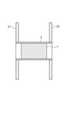
The first embodiment of the present invention will be described with reference to FIGS. 1 to 10. FIG. 1 is a cross-sectional view showing an example of a usage state of the
第1の実施形態では、建物内部の空気を換気する際に用いる換気ユニットを構成するファンユニット1について説明する。ファンユニット1は、例えば図1で示すように、建物の内壁21と外壁22とに設けられた貫通孔に挿入された円筒状のパイプ部材3(スリーブ管)の内部に挿入される。そして、ファンユニット1が有する後述するファン14が回転することで、建物の内部の空気を換気する。後述するように、換気ユニットを構成する部品のうちファン14や蓄熱エレメント13などをファンユニット1として構成することで、換気する機能を実現するために必要な部品数などを削減することが可能となる。また、本実施形態におけるファンユニット1によると、換気ユニットを容易に取り付けることが可能となり、また、換気ユニットを取り付ける際のコストを削減することが可能となる。 In the first embodiment, the
なお、図1では図示していないが、パイプ部材3やファンユニット1を設置する箇所のうち内壁21側には、例えば、図示しない室内側フードや防塵フィルターなどを設けることが出来る。また、パイプ部材3やファンユニット1を設置する箇所のうち外壁22側には、例えば、図示しない屋外側フィルターなどを設けることが出来る。このように、内壁21側や外壁22側には、図示しない構成を有していても構わない。 Although not shown in FIG. 1, for example, an indoor hood or a dustproof filter (not shown) can be provided on the
また、建物の壁には、上記ファンユニット1などから構成される換気ユニットを、例えば一対設けることが出来る。一対の換気ユニットは、例えば、一方が建物の外部から内部に吸気するよう動作し、他方が建物の内部から外部に排気するよう動作する。このように換気ユニットを一対設けそれぞれが連動して動作するよう構成することで、建物内部の空気を効率的に換気することが出来る。なお、建物の壁には、3以上の任意の数の換気ユニットを設けても構わない。 Further, for example, a pair of ventilation units composed of the
図2は、ファンユニット1の全体の構成の一例を示す斜視図である。また、図3は、ファンユニット1を構成する各構成部品の一例を示す分解図である。図2、図3を参照すると、ファンユニット1は、第1筒状部11と、第2筒状部12と、蓄熱エレメント13と、ファン14と、4本の結束バンド15と、環状部材16と、から構成されている。例えば、第1筒状部11と第2筒状部12とは、当該第1筒状部11と当該第2筒状部12とにより蓄熱エレメント13を挟み込んだ状態で、4本の結束バンド15により連結されている。また、ファン14は、第1筒状部11の内部であって、第1筒状部11が有するガード部116と蓄熱エレメント13との間に設置されている。また、環状部材16は、第1筒状部11の内部に嵌め込まれている。 FIG. 2 is a perspective view showing an example of the overall configuration of the
図4は、第1筒状部11(第1の保持部材)の構成の一例を示している。図4で示すように、第1筒状部11は、例えば、円筒形状を有する樹脂製の部材である。図4を参照すると、第1筒状部11は、一方の端部にガード部116が形成されており、他方は開口している。図2、図3で示すように、蓄熱エレメント13は、第1筒状部11のうちの開口している側(つまり、ガード部116を有する側とは反対側)から第1筒状部11の内部に挿入されることになる。 FIG. 4 shows an example of the configuration of the first tubular portion 11 (first holding member). As shown in FIG. 4, the first
第1筒状部11の外周面には、結束バンド15を通すための凹部である結束バンド用溝111が形成されている。結束バンド用溝111は、第1筒状部11の外周面のうち、開口側端部からガード部116を有する側の方向に向かって所定長さ分形成されている。また、結束バンド用溝111のうちガード部116側の端部には、結束バンド15が挿通するための結束バンド挿通用貫通孔112が形成されている。このような構成により、結束バンド15は、結束バンド用溝111に沿って第1筒状部11の外周面を通った後、結束バンド挿通用貫通孔112を通って第1筒状部11の内部に挿入されることになる。なお、第1筒状部11の外周面上には、例えば、上記結束バンド用溝111が4箇所形成されている。例えば、第1筒状部11をガード部116から開口側に向かう方向(ファン14が回転する軸方向)で見た際に円形状の第1筒状部を四等分する4箇所であって、後述する枠部の間に位置する箇所に、それぞれ結束バンド用溝111が形成されている。第1筒状部11の外周面に形成される結束バンド用溝111の数は、2つなど図4で例示している以外であっても構わない。 A
第1筒状部11の内周面のうち、結束バンド挿通用貫通孔112が形成されている位置に応じた位置には、結束バンド15の第1筒状部11側の端部を係止する結束バンド係止部113が形成されている。例えば、後述するように、結束バンド15には所定の間隔で複数の溝部が形成されており、当該溝部と結束バンド係止部113に設けられた爪部とが係合することで、結束バンド15が結束バンド係止部113に係止される。換言すると、結束バンド15は、結束バンド用溝111に沿って第1筒状部11の外周面を通った後、結束バンド挿通用貫通孔112を通って第1筒状部11の内部に挿入され、第1筒状部11の内部で結束バンド係止部113に係止される。なお、結束バンド15の端部が結束バンド係止部113に係止可能であれば、結束バンド15を結束バンド係止部113に係止するための構成は、上記例示した場合に限定されない。結束バンド15は、例えば、熱圧着などの手段を用いて結束バンド係止部113に係止されても構わない。 On the inner peripheral surface of the first
また、第1筒状部11の内周面のうち開口側の所定位置には、第1筒状部11の内部に環状部材16を嵌め込む際に用いる環状部材係止部114が形成されている。環状部材係止部114は、例えば、ガード部116側に頂点を有する形状を有しており、開口側からガード部116側への環状部材16の移動を許容する一方で、ガード部116側で環状部材16を係止して、ガード部116側から開口側へ環状部材16を移動しないようにする。例えば、このような構成により、環状部材16は、環状部材係止部114の内部に嵌め込むことが出来る。なお、環状部材係止部114は、例えば、第1筒状部11の外周面に結束バンド用溝111が形成されることで第1筒状部11の内周面に形成される凸部を挟み込むように形成されている。つまり、環状部材係止部114は、第1筒状部11の内周面に例えば8つ形成されている(8つ以外でも構わない)。 Further, an annular
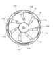
また、上述したように、第1筒状部11のうちの一方の端部には、ガード部116が形成されている。ガード部116は、例えば、ファン14の回転軸が位置しファン14を回転させる図示しないモーターなどを設置可能な中心部と、ファン14の回転軸の中心と同心円状となる複数の環状部と、第1筒状部の半径方向に設けられた4本の枠部と、から構成されている。ガード部116は、上記構成により、指などの物体が第1筒状部11の外部からファン14方向に侵入することを防止する一方で、ファン14が回転することなどにより生じる空気の流れを許容する。つまり、ガード部116は、空気が流れる隙間を有するよう構成されている、ということも出来る。 Further, as described above, a
また、ガード部116の所定位置(例えば、上記枠部の一つと第1筒状部11の内周面との交点付近)には、コネクタ挿通部115が形成されている。コネクタ挿通部115には、図示しないモーターなどと接続する図示しないコネクタが挿通されている。ファン14のモーターは、コネクタ挿通部115に挿通するコネクタを介して、外部装置から電力や各種命令(例えば、回転停止命令や回転開始命令、回転方向を指示する命令など)を受信する。 Further, a
図5は、環状部材16の構成の一例を示している。図5で示すように、環状部材16は、例えば、略環状(略筒状)に形成された樹脂製の部材である。図5を参照すると、環状部材16は、外周面に4つの溝161を有している。溝161は、例えば、第1筒状部11の結束バンド係止部113が設けられている位置に応じた位置に形成されている。また、環状部材16には、切れ目162が形成されている。このように環状部材16に切れ目162を形成することで、環状部材16は、切れ目162を当接させたり離したりすることで、容易に環状部材16の径を変更することが出来る。換言すると、環状部材16は、切れ目162の両端部を当接させることで、環状部材16の径を容易に小さくすることが出来る。これにより、例えば、環状部材16をより容易に第1筒状部11に嵌め込むことなどが出来るようになる。 FIG. 5 shows an example of the configuration of the
また、環状部材16は、例えば、結束バンド係止部113の高さに応じた厚みを有している。上述したように、第1筒状部11の内周面には、結束バンド係止部113が設けられている。そのため、第1筒状部11の内面のうち結束バンド係止部113が設けられていない箇所とファン14の羽根との間には、結束バンド係止部113が設けられていることに起因する隙間が形成されることになる。本実施形態においては、図6で示すように、第1筒状部11の内部に環状部材16を嵌め込むことで、上記第1筒状部11の内面とファン14の羽根との間に形成される隙間を埋める。つまり、環状部材16は、第1筒状部11とファン14の羽根との間に形成される隙間を埋める隙間埋め部材として機能する。このように、環状部材16を用いて第1筒状部11の内面とファン14の羽根との間の隙間を埋めることで、後述するように、ファンユニット1のPQ特性(風量―静圧特性)を向上させることが出来る。 Further, the
ファン14は、図2で示すように、第1筒状部11の内部のうちガード部116と蓄熱エレメント13との間に設置される。例えば、第1筒状部11の内部に環状部材16を嵌め合せ、ファン14を設置した後に、当該第1筒状部11の内部に蓄熱エレメントを挿入することになる。ファン14は、例えば、ガード部116の中心部に、図示しないモーターを介して設置されており、図示しないモーターが回転することにより第1筒状部11の内部で回転する。なお、上述したように、モーターは、コネクタ挿通部115に挿通するコネクタを介して、外部装置から電力や各種命令を受信する。 As shown in FIG. 2, the
図7は、蓄熱エレメント13の構成の一例を示している。図7で示すように、蓄熱エレメント13は、例えば、所定の長さを有する円筒状の部材であり、酸化アルミニウムなどの金属酸化物やセラミックなどから構成されている。例えば、蓄熱エレメント13は、一端と他端とが多数の孔131で連通した多孔質部材にて構成されている。このような構成により、蓄熱エレメント13の内部には、一端から他端にかけて形成された孔131を通過した空気の熱が蓄積されたり、一端から他端にかけて空気が通過する際に空気が蓄熱エレメント13に蓄積された熱を吸収したりする。 FIG. 7 shows an example of the configuration of the
なお、本実施形態においては、孔131の形状は特に限定しない。孔131の形状は、例えば、円形や四角形などであっても構わないし、六角形(ハニカム構造)などであっても構わない。 In this embodiment, the shape of the
図8は、第2筒状部12(第2の保持部材)の構成の一例を示している。図8で示すように、第2筒状部12は、例えば、円筒形状を有する樹脂製の部材である。図8を参照すると、第2筒状部12は、一方の端部近傍に結束バンド係止部123を有しており、他方は開口している。図2、図3で示すように、蓄熱エレメント13は、結束バンド係止部123を有する側とは反対側から第2筒状部12の内部に挿入されることになる。 FIG. 8 shows an example of the configuration of the second tubular portion 12 (second holding member). As shown in FIG. 8, the second
第2筒状部12の外周面には、結束バンド15を通すための凹部である結束バンド用溝121が形成されている。結束バンド用溝121は、第2筒状部12の外周面のうち、開口側端部から結束バンド係止部123を有する側の方向に向かって所定長さ分形成されている。また、結束バンド用溝121のうち結束バンド係止部123が形成されている側の端部には、結束バンド15が挿通するための結束バンド挿通用貫通孔122が形成されている。このような構成により、結束バンド15は、結束バンド用溝121に沿って第2筒状部12の外周面を通った後、結束バンド挿通用貫通孔122を通って第2筒状部12の内部に挿入されることになる。なお、第2筒状部12の外周面上には、例えば、上記結束バンド用溝121が4箇所形成されている。例えば、結束バンド用溝121は、第1筒状部11の外周面上に形成された結束バンド用溝111の位置に応じた位置に形成されている。第2筒状部12の外周面に形成される結束バンド用溝121の数は、2つなど図8で例示している以外であっても構わない。ただし、結束バンド用溝121の数は、結束バンド用溝111の数と同じであることが望ましい。 A
第2筒状部12の内周面のうち、結束バンド挿通用貫通孔122が形成されている位置に応じた位置には、結束バンド15の第2筒状部12側の端部を係止する結束バンド係止部123が形成されている。例えば、後述するように、結束バンド15には所定の間隔で複数の溝部が形成されており、当該溝部と結束バンド係止部123に設けられた爪部とが係合することで、結束バンド15が結束バンド係止部123に係止される。換言すると、結束バンド15は、結束バンド用溝121に沿って第2筒状部12の外周面を通った後、結束バンド挿通用貫通孔122を通って第2筒状部12の内部に挿入され、第2筒状部12の内部で結束バンド係止部123に係止される。なお、結束バンド15の端部が結束バンド係止部123に係止可能であれば、結束バンド15を結束バンド係止部123に係止するための構成は、上記例示した場合に限定されない。結束バンド15は、例えば、熱圧着などの手段を用いて結束バンド係止部123に係止されても構わない。 On the inner peripheral surface of the second
結束バンド15(連結手段)は、例えば、可撓性を有する樹脂製のバンドである。結束バンド15は、図示しない複数の溝部を備えて構成されており、結束バンド係止部113や結束バンド係止部123などが有する爪部と係合することで、結束バンド15中の任意の箇所で結束バンド係止部113、123に係止可能なよう構成されている。結束バンド15は、例えば、タイラップ(登録商標)やインシュロック(登録商標)などと呼ばれるものであっても構わない。なお、結束バンド15は、一般的に、複数の溝部が形成されたバンド部と爪部を有するロック部とを有しているが、本実施形態において説明する結束バンド15は、少なくともバンド部に相当する構成を有していれば、ロック部に相当する構成は有していなくても構わない。 The binding band 15 (connecting means) is, for example, a flexible resin band. The binding
ファンユニット1は、例えば、上述したような、第1筒状部11と、第2筒状部12と、蓄熱エレメント13と、ファン14と、4本の結束バンド15と、環状部材16と、を有している。そして、例えば、ファンユニット1は、第1筒状部11の内部に環状部材16を嵌め込むとともに、ファン14を設置した状態で、当該第1筒状部11と第2筒状部12とにより蓄熱エレメント13を挟み込み、挟み込んだ状態の第1筒状部11と第2筒状部12とを結束バンド15により連結することにより構成されている。 The
以上のように、本実施形態におけるファンユニット1は、第1筒状部11と、第2筒状部12と、蓄熱エレメント13と、ファン14と、4本の結束バンド15と、環状部材16と、を有している。また、第1筒状部11は、当該第1筒状部11の内部にファン14を設置可能なよう構成されている。このように、本実施形態におけるファンユニット1によると、非常に少ない部品点数でファンユニットを実現することが出来る。そのため、本実施形態におけるファンユニット1によると、住宅などの建物の壁に設置するファンユニットを簡易な構造で実現することで難しい、という問題を解決することが出来る。また、本実施形態におけるファンユニット1によると、換気ユニットを容易に取り付けることが可能となり、また、換気ユニットを取り付ける際のコストを削減することが可能となる。 As described above, the
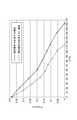
また、図9は、第1筒状部11の内部に環状部材16を嵌め込んだ場合の風量―静圧特性と第1筒状部11の内部に環状部材16を嵌め込まなかった場合の風量―静圧特性との一例について示している。具体的には、図9で示すグラフは、X軸が風量(m3/h)を示しており、Y軸が圧力(InH2O)を示している。図9を参照すると、環状部材16を第1筒状部11の内部に嵌め込むことで、ファンユニット1により生じる風量が増していることが分かる。つまり、第1筒状部11の内部に環状部材16を嵌め込むことにより、より効率的に建物内部の空気を換気することが可能となることが分かる。Further, FIG. 9 shows the air volume when the
なお、本実施形態においては、ファンユニット1は、環状部材16を有するとした。しかしながら、ファンユニット1は、環状部材16を有していなくても構わない。換言すると、ファンユニット1は、第1筒状部11と、第2筒状部12と、蓄熱エレメント13と、ファン14と、4本の結束バンド15と、から構成されても構わない。 In this embodiment, the
また、本実施形態においては、第1筒状部11と第2筒状部12とを連結する連結手段として、結束バンド15を例示した。しかしながら、第1筒状部11と第2筒状部12とは、紐などの結束バンド15以外の連結手段により連結されても構わない。 Further, in the present embodiment, a binding
また、第1筒状部11のガード部が設けられている側の外側には、図10で示すように、持ち手17を設けることが出来る。持ち手17は、例えば、結束バンド15と同様の素材により構成されている。第1筒状部11に持ち手17を設けることで、より容易にファンユニット1を設置することが可能となる。 Further, as shown in FIG. 10, a
ここで、上述したファン14の中心部には、当該ファン14を電気的に駆動する構造であるモーター及び基板が装備されているが、モーター及び基板を防水加工して装備してもよい。つまり、ファン14と共に装備されている駆動構造を防水加工することで、ファン14自体を防水加工してもよい。防水加工の一例としては、例えば、基板は、その表面を樹脂スプレーで防水皮膜し、モーターは、内部に樹脂を埋め込むことで行う。但し、ファン14の防水加工はいかなる方法で行ってもよい。 Here, the central portion of the
以上のようにファン14自体を防水加工することで、上述したファンユニット1全体が防水仕様となる。このため、ファンユニット1をそのまま洗浄することができ、例えば、食洗機で水洗いすることができる。その結果、ファンユニット1の洗浄の手間を軽減でき、容易に清潔に保つことができる。なお、上述したようにモーター内部を樹脂で封止することで、金属部品の塩害も抑制することができる。 By waterproofing the
また、上述したファンユニット1のファン14の構成を、2層のプロペラ構造としてもよい。具体的には、ファン14の内部、つまり、ファン14と蓄熱エレメント13との間に、第2の羽根部材である固定プロペラ(図示せず)を追加で装備してもよい。この固定プロペラは、ファン14が回転することによって生成された気流を整流する機能を有し、例えば、ファン14によって生成された気流を外周側から中心側に導くよう形成された羽根を有する。このようにファン14と蓄熱エレメント13との間に固定プロペラを設けることで、ファン14によって生成された気流が蓄熱エレメント13の外周側といった一部のみに集中して通過しないよう、当該気流を蓄熱エレメント13の全面に均等に導くことができる。なお、第2の羽根部材は、必ずしも固定されていることに限定されず、ファン14による気流を整流する機能を有していれば、いかなる構造であってもよい。 Further, the configuration of the
以上、上記各実施形態を参照して本願発明を説明したが、本願発明は、上述した実施形態に限定されるものではない。本願発明の構成や詳細には、本願発明の範囲内で当業者が理解しうる様々な変更をすることが出来る。 Although the invention of the present application has been described above with reference to each of the above embodiments, the invention of the present application is not limited to the above-described embodiment. Various changes that can be understood by those skilled in the art can be made to the structure and details of the present invention within the scope of the present invention.
1 ファンユニット
11 第1筒状部
111 結束バンド用溝
112 結束バンド挿通用貫通孔
113 結束バンド係止部
114 環状部材係止部
115 コネクタ挿通部
116 ガード部
12 第2筒状部
121 結束バンド用溝
122 結束バンド挿通用貫通孔
123 結束バンド係止部
13 蓄熱エレメント
131 孔
14 ファン
15 結束バンド
16 環状部材
161 溝
162 切れ目
17 持ち手
21 内壁
22 外壁
3 パイプ部材1
Claims (5)
Translated fromJapanese筒状の形状を有し、前記蓄熱エレメントのうちの一方の側を内部に挿入する第1の保持部材と、
筒状の形状を有し、前記蓄熱エレメントのうちの他方の側を内部に挿入する第2の保持部材と、を備え、
前記第1の保持部材は、空気が流れる隙間を有するガード部を一方の端部に有し、前記ガード部を有する側とは反対側から前記蓄熱エレメントを内部に挿入するよう構成されるとともに、前記ガード部と前記蓄熱エレメントの間にファンを設置可能なよう構成され、
前記第1の保持部材と前記第2の保持部材とは、前記第1の保持部材と前記第2の保持部材とで前記蓄熱エレメントを挟み込んだ状態で、所定の連結手段により連結されており、
前記第1の保持部材の内周面には、前記連結手段を係止する第1係止部が形成されており、
前記第2の保持部材の内周面には、前記連結手段を係止する第2係止部が形成されており、
前記第1の保持部材の内周面に前記第1係止部を形成することで、前記第1の保持部材の内周面と前記ファンの羽根との間に隙間が形成されており、
前記第1の保持部材の内部に嵌め込むことで前記第1の保持部材の内周面と前記ファンの羽根との間の隙間を埋める筒状の隙間埋め部材を有する
ファンユニット。Cylindrical heat storage element and
A first holding member having a cylindrical shape and inserting one side of the heat storage element into the inside,
It has a cylindrical shape and includes a second holding member for inserting the other side of the heat storage element into the inside.
The first holding member has a guard portion having a gap through which air flows at one end thereof, and is configured to insert the heat storage element inside from the side opposite to the side having the guard portion. It is configured so that a fan can be installed between the guard portion and the heat storage element.
The first holding member and the second holding member are connected by a predetermined connecting means in a state where the heat storage element is sandwiched between the first holding member and the second holding member.
A first locking portion for locking the connecting means is formed on the inner peripheral surface of the first holding member.
A second locking portion for locking the connecting means is formed on the inner peripheral surface of the second holding member.
By forming the first locking portion on the inner peripheral surface of the first holding member, a gap is formed between the inner peripheral surface of the first holding member and the blade of the fan.
It has a tubular gap filling member that fills the gap between the inner peripheral surface of the first holding member and the blades of the fan by being fitted inside the first holding member.
Fan unit.
前記連結手段は、複数の溝部を有するバンド部により構成されている
ファンユニット。The fan unit according to claim1 .
The connecting means is a fan unit composed of a band portion having a plurality of groove portions.
前記第1の保持部材のうちの前記ガード部側端部には、持ち手が形成されている
ファンユニット。The fan unit accordingto claim 1 or 2 .
A fan unit having a handle formed on the guard portion side end portion of the first holding member.
前記ファンに、当該ファンを電気的に駆動する構造を設け、当該ファンを駆動する構造は防水加工されている、
ファンユニット。The fan unit according to any one of claims 1 to3 .
The fan is provided with a structure for electrically driving the fan, and the structure for driving the fan is waterproofed.
Fan unit.
前記ファンと前記蓄熱エレメントとの間に、前記ファンによって生成される気流を整流する第2の羽根部材を設けた、
ファンユニット。The fan unit according to any one of claims 1 to4 .
A second blade member for rectifying the airflow generated by the fan is provided between the fan and the heat storage element.
Fan unit.
Priority Applications (2)
| Application Number | Priority Date | Filing Date | Title |
|---|---|---|---|
| KR1020180064111AKR20190004218A (en) | 2017-07-03 | 2018-06-04 | Fan unit |
| EP18180040.0AEP3425294B1 (en) | 2017-07-03 | 2018-06-27 | Fan unit |
Applications Claiming Priority (2)
| Application Number | Priority Date | Filing Date | Title |
|---|---|---|---|
| JP2017130183 | 2017-07-03 | ||
| JP2017130183 | 2017-07-03 |
Publications (2)
| Publication Number | Publication Date |
|---|---|
| JP2019015490A JP2019015490A (en) | 2019-01-31 |
| JP7041504B2true JP7041504B2 (en) | 2022-03-24 |
Family
ID=65358298
Family Applications (1)
| Application Number | Title | Priority Date | Filing Date |
|---|---|---|---|
| JP2017233963AActiveJP7041504B2 (en) | 2017-07-03 | 2017-12-06 | Fan unit |
Country Status (1)
| Country | Link |
|---|---|
| JP (1) | JP7041504B2 (en) |
Families Citing this family (2)
| Publication number | Priority date | Publication date | Assignee | Title |
|---|---|---|---|---|
| EP4325066A4 (en)* | 2021-05-19 | 2024-09-25 | Panasonic Intellectual Property Management Co., Ltd. | AIR FLOW CONTROL SYSTEM |
| CN120659957A (en)* | 2023-02-08 | 2025-09-16 | 夏普株式会社 | Heat exchange device and full heat exchange ventilation system |
Citations (4)
| Publication number | Priority date | Publication date | Assignee | Title |
|---|---|---|---|---|
| JP2001280658A (en) | 2000-03-31 | 2001-10-10 | Toshiba Kyaria Kk | Pipe fan |
| JP2007085687A (en) | 2005-09-26 | 2007-04-05 | Mitsubishi Electric Corp | Ventilation equipment |
| US20140273797A1 (en) | 2011-05-13 | 2014-09-18 | John Borsting Jensen | Ventilation System With A Rotatable Air Flow Generator And One Or More Movable Registers And Method For Obtaining Ventilation Through The Ventilation System |
| JP2016145673A (en) | 2015-02-06 | 2016-08-12 | パッシブエネルギージャパン株式会社 | Ventilation system |
Family Cites Families (2)
| Publication number | Priority date | Publication date | Assignee | Title |
|---|---|---|---|---|
| US5050667A (en)* | 1990-05-15 | 1991-09-24 | Erling Berner | Air ventilation and heat exchange apparatus |
| JP3309062B2 (en)* | 1997-04-08 | 2002-07-29 | 松下精工株式会社 | Heat exchange element |
- 2017
- 2017-12-06JPJP2017233963Apatent/JP7041504B2/enactiveActive
Patent Citations (4)
| Publication number | Priority date | Publication date | Assignee | Title |
|---|---|---|---|---|
| JP2001280658A (en) | 2000-03-31 | 2001-10-10 | Toshiba Kyaria Kk | Pipe fan |
| JP2007085687A (en) | 2005-09-26 | 2007-04-05 | Mitsubishi Electric Corp | Ventilation equipment |
| US20140273797A1 (en) | 2011-05-13 | 2014-09-18 | John Borsting Jensen | Ventilation System With A Rotatable Air Flow Generator And One Or More Movable Registers And Method For Obtaining Ventilation Through The Ventilation System |
| JP2016145673A (en) | 2015-02-06 | 2016-08-12 | パッシブエネルギージャパン株式会社 | Ventilation system |
Also Published As
| Publication number | Publication date |
|---|---|
| JP2019015490A (en) | 2019-01-31 |
Similar Documents
| Publication | Publication Date | Title |
|---|---|---|
| JP7041504B2 (en) | Fan unit | |
| TWI555915B (en) | Lead wire engaging structure and electric apparatus | |
| US9957978B2 (en) | Ventilation system and ventilation fan housing thereof | |
| FI3085962T3 (en) | Bidirectional axial fan device | |
| AU2019222957A1 (en) | Wall sleeve system for a ventilation system | |
| CN214536756U (en) | Fresh air conditioner | |
| KR20190004218A (en) | Fan unit | |
| JP2017150693A (en) | Blower | |
| CN111174365A (en) | fan unit | |
| JP6479219B2 (en) | Ventilation fan | |
| JP6203108B2 (en) | Ventilation fan | |
| JP2001336795A (en) | Ventilation equipment | |
| KR101563205B1 (en) | Ventilation Fan | |
| US5871339A (en) | Ventilation arrangement for a casing covering a compressor drive unit | |
| KR101450862B1 (en) | Connecting means for duct | |
| JP2007154856A (en) | Water entering prevention structure of blower | |
| US20150167692A1 (en) | Fan assembly and fan hub cap | |
| EP3889436A1 (en) | Fans for ventilation | |
| TWI577946B (en) | Air-exchanging device | |
| KR20120002880A (en) | motor | |
| JP4805041B2 (en) | Ventilation fan | |
| JP2008212004A (en) | Blower with check valve, and construction of double film structure, using the same | |
| JP4695984B2 (en) | Ventilation opening parts and ventilation equipment | |
| WO2018179186A1 (en) | Ventilation fan for duct | |
| JPH1123027A (en) | Ventilation fan |
Legal Events
| Date | Code | Title | Description |
|---|---|---|---|
| A621 | Written request for application examination | Free format text:JAPANESE INTERMEDIATE CODE: A621 Effective date:20201023 | |
| A977 | Report on retrieval | Free format text:JAPANESE INTERMEDIATE CODE: A971007 Effective date:20210927 | |
| A131 | Notification of reasons for refusal | Free format text:JAPANESE INTERMEDIATE CODE: A131 Effective date:20211005 | |
| A521 | Request for written amendment filed | Free format text:JAPANESE INTERMEDIATE CODE: A523 Effective date:20211021 | |
| TRDD | Decision of grant or rejection written | ||
| A01 | Written decision to grant a patent or to grant a registration (utility model) | Free format text:JAPANESE INTERMEDIATE CODE: A01 Effective date:20220308 | |
| A61 | First payment of annual fees (during grant procedure) | Free format text:JAPANESE INTERMEDIATE CODE: A61 Effective date:20220311 | |
| R150 | Certificate of patent or registration of utility model | Ref document number:7041504 Country of ref document:JP Free format text:JAPANESE INTERMEDIATE CODE: R150 | |
| R250 | Receipt of annual fees | Free format text:JAPANESE INTERMEDIATE CODE: R250 |