JP7040629B2 - Encoding device, coding method, coding program, decoding device, decoding method and decoding program - Google Patents
Encoding device, coding method, coding program, decoding device, decoding method and decoding programDownload PDFInfo
- Publication number
- JP7040629B2 JP7040629B2JP2020547555AJP2020547555AJP7040629B2JP 7040629 B2JP7040629 B2JP 7040629B2JP 2020547555 AJP2020547555 AJP 2020547555AJP 2020547555 AJP2020547555 AJP 2020547555AJP 7040629 B2JP7040629 B2JP 7040629B2
- Authority
- JP
- Japan
- Prior art keywords
- block
- intra prediction
- processed
- prediction mode
- unit
- Prior art date
- Legal status (The legal status is an assumption and is not a legal conclusion. Google has not performed a legal analysis and makes no representation as to the accuracy of the status listed.)
- Active
Links
Images


Classifications
- H—ELECTRICITY
- H04—ELECTRIC COMMUNICATION TECHNIQUE
- H04N—PICTORIAL COMMUNICATION, e.g. TELEVISION
- H04N19/00—Methods or arrangements for coding, decoding, compressing or decompressing digital video signals
- H04N19/10—Methods or arrangements for coding, decoding, compressing or decompressing digital video signals using adaptive coding
- H04N19/102—Methods or arrangements for coding, decoding, compressing or decompressing digital video signals using adaptive coding characterised by the element, parameter or selection affected or controlled by the adaptive coding
- H04N19/103—Selection of coding mode or of prediction mode
- H04N19/105—Selection of the reference unit for prediction within a chosen coding or prediction mode, e.g. adaptive choice of position and number of pixels used for prediction
- H—ELECTRICITY
- H04—ELECTRIC COMMUNICATION TECHNIQUE
- H04N—PICTORIAL COMMUNICATION, e.g. TELEVISION
- H04N19/00—Methods or arrangements for coding, decoding, compressing or decompressing digital video signals
- H04N19/50—Methods or arrangements for coding, decoding, compressing or decompressing digital video signals using predictive coding
- H04N19/593—Methods or arrangements for coding, decoding, compressing or decompressing digital video signals using predictive coding involving spatial prediction techniques
- H—ELECTRICITY
- H04—ELECTRIC COMMUNICATION TECHNIQUE
- H04N—PICTORIAL COMMUNICATION, e.g. TELEVISION
- H04N19/00—Methods or arrangements for coding, decoding, compressing or decompressing digital video signals
- H04N19/10—Methods or arrangements for coding, decoding, compressing or decompressing digital video signals using adaptive coding
- H04N19/102—Methods or arrangements for coding, decoding, compressing or decompressing digital video signals using adaptive coding characterised by the element, parameter or selection affected or controlled by the adaptive coding
- H04N19/13—Adaptive entropy coding, e.g. adaptive variable length coding [AVLC] or context adaptive binary arithmetic coding [CABAC]
- H—ELECTRICITY
- H04—ELECTRIC COMMUNICATION TECHNIQUE
- H04N—PICTORIAL COMMUNICATION, e.g. TELEVISION
- H04N19/00—Methods or arrangements for coding, decoding, compressing or decompressing digital video signals
- H04N19/10—Methods or arrangements for coding, decoding, compressing or decompressing digital video signals using adaptive coding
- H04N19/134—Methods or arrangements for coding, decoding, compressing or decompressing digital video signals using adaptive coding characterised by the element, parameter or criterion affecting or controlling the adaptive coding
- H04N19/157—Assigned coding mode, i.e. the coding mode being predefined or preselected to be further used for selection of another element or parameter
- H04N19/159—Prediction type, e.g. intra-frame, inter-frame or bidirectional frame prediction
- H—ELECTRICITY
- H04—ELECTRIC COMMUNICATION TECHNIQUE
- H04N—PICTORIAL COMMUNICATION, e.g. TELEVISION
- H04N19/00—Methods or arrangements for coding, decoding, compressing or decompressing digital video signals
- H04N19/10—Methods or arrangements for coding, decoding, compressing or decompressing digital video signals using adaptive coding
- H04N19/169—Methods or arrangements for coding, decoding, compressing or decompressing digital video signals using adaptive coding characterised by the coding unit, i.e. the structural portion or semantic portion of the video signal being the object or the subject of the adaptive coding
- H04N19/17—Methods or arrangements for coding, decoding, compressing or decompressing digital video signals using adaptive coding characterised by the coding unit, i.e. the structural portion or semantic portion of the video signal being the object or the subject of the adaptive coding the unit being an image region, e.g. an object
- H04N19/176—Methods or arrangements for coding, decoding, compressing or decompressing digital video signals using adaptive coding characterised by the coding unit, i.e. the structural portion or semantic portion of the video signal being the object or the subject of the adaptive coding the unit being an image region, e.g. an object the region being a block, e.g. a macroblock
- H—ELECTRICITY
- H04—ELECTRIC COMMUNICATION TECHNIQUE
- H04N—PICTORIAL COMMUNICATION, e.g. TELEVISION
- H04N19/00—Methods or arrangements for coding, decoding, compressing or decompressing digital video signals
- H04N19/46—Embedding additional information in the video signal during the compression process
- H—ELECTRICITY
- H04—ELECTRIC COMMUNICATION TECHNIQUE
- H04N—PICTORIAL COMMUNICATION, e.g. TELEVISION
- H04N19/00—Methods or arrangements for coding, decoding, compressing or decompressing digital video signals
- H04N19/90—Methods or arrangements for coding, decoding, compressing or decompressing digital video signals using coding techniques not provided for in groups H04N19/10-H04N19/85, e.g. fractals
- H04N19/91—Entropy coding, e.g. variable length coding [VLC] or arithmetic coding
Landscapes
- Engineering & Computer Science (AREA)
- Multimedia (AREA)
- Signal Processing (AREA)
- Compression Or Coding Systems Of Tv Signals (AREA)
Description
Translated fromJapanese本発明は、符号化装置、符号化方法、符号化プログラム、復号装置、復号方法及び復号プログラムに関する。 The present invention relates to a coding device, a coding method, a coding program, a decoding device, a decoding method and a decoding program.
動画像データの圧縮符号化に関する国際標準として、H.265/HEVCが知られている。H.265/HEVCでは、イントラ予測とインタ予測の2つの予測方法が採用されており、イントラ予測には、更に、3種類の予測モード(プレーナ予測、直流予測、角度予測)が規定されている。 As an international standard for compression coding of moving image data, H. 265 / HEVC is known. H. In 265 / HEVC, two prediction methods, intra prediction and inter prediction, are adopted, and three types of prediction modes (planar prediction, DC prediction, and angle prediction) are further defined for intra prediction.
このうち、角度予測モードによるイントラ予測では、予め定義されたN個の異なる角度(参照方向)のうち、選択された参照方向を参照することで、処理対象のブロックの画素値を予測する。 Of these, in the intra prediction by the angle prediction mode, the pixel value of the block to be processed is predicted by referring to the selected reference direction from the N different angles (reference directions) defined in advance.
角度予測モードによるイントラ予測の場合、符号化装置では、参照方向の数(N個)に応じたビット数の二値信号を、発生確率モデルを用いて算術符号化することで、符号化ストリームを生成する。 In the case of intra-prediction in the angle prediction mode, the coding device arithmetically encodes a binary signal with a number of bits corresponding to the number (N) in the reference direction using an occurrence probability model to generate a coded stream. Generate.
ここで、従来の符号化装置では、発生確率の推定が困難な二値信号については、発生確率を0.5に固定するバイパスモードを用いて算術符号化を行っていた。このため、かかる二値信号については、符号化ストリーム生成時の符号量の削減が十分ではないといった問題があった。更に、かかる問題は、動画像データの圧縮符号化に関する次世代の国際標準であるVVC(Versatile Video Codec)においても同様に起こり得る。 Here, in the conventional coding apparatus, for a binary signal whose probability of occurrence is difficult to estimate, arithmetic coding is performed using a bypass mode in which the probability of occurrence is fixed at 0.5. Therefore, for such a binary signal, there is a problem that the reduction of the code amount at the time of generating the coded stream is not sufficient. Further, such a problem may occur in VVC (Versatile Video Codec), which is the next-generation international standard for compression coding of moving image data.
一つの側面では、イントラ予測において、符号量を削減することを目的としている。 One aspect is aimed at reducing the amount of code in intra-prediction.
一態様によれば、符号化装置は、
処理対象のブロックでのイントラ予測において選択された参照方向を示す値を、前記処理対象のブロックの形状に応じて変換することで、参照方向に応じた値を生成する変換部と、
前記処理対象のブロックに隣接する隣接ブロックでのイントラ予測において生成された、前記参照方向に応じた値から、前記処理対象のブロックでの予測値を算出する算出部と、
前記処理対象のブロックでのイントラ予測において生成された、前記参照方向に応じた値と前記予測値とに基づいて、算術符号化のための二値信号を生成する生成部と、を有し、
前記生成部は、
前記参照方向に応じた値に基づいて生成された二値信号の上位mビット(mは1以上の整数)の値について、前記予測値との排他的論理和を演算することで、前記算術符号化のための二値信号を生成する。
According to one aspect, the encoding device is
A conversion unit that generates a value according to the reference direction by converting a value indicating the reference direction selected in the intra prediction in the block to be processed according to the shape of the block to be processed.
A calculation unit that calculates the predicted value in the block to be processed from the value corresponding to the reference direction generated in the intra prediction in the adjacent block adjacent to the block to be processed.
It has a generator that generates a binary signal for arithmetic coding based on the value corresponding to the reference direction and the predicted value generated in the intra prediction in the block to be processed.
The generator is
The arithmetic code is obtained by calculating the exclusive OR with the predicted value for the value of the upper m bits (m is an integer of 1 or more) of the binary signal generated based on the value corresponding to the reference direction. Generates a binary signal for conversion .
イントラ予測において、符号量を削減することができる。 In intra prediction, the amount of code can be reduced.
以下、各実施形態について添付の図面を参照しながら説明する。なお、本明細書及び図面において、実質的に同一の機能構成を有する構成要素については、同一の符号を付することにより重複した説明を省略する。 Hereinafter, each embodiment will be described with reference to the attached drawings. In the present specification and the drawings, components having substantially the same functional configuration are designated by the same reference numerals, so that duplicate description will be omitted.
[第1の実施形態]
<イントラ予測モード情報の符号化処理及び復号処理の概要>
はじめに、第1の実施形態に係る符号化装置が、イントラ予測を行う場合の、イントラ予測モード情報の符号化処理と、対応する復号装置がイントラ予測モード情報の符号化ストリームを復号する場合の復号処理の概要について説明する。[First Embodiment]
<Outline of coding processing and decoding processing of intra prediction mode information>
First, the coding device according to the first embodiment encodes the intra prediction mode information when the intra prediction is performed, and the corresponding decoding device decodes the coded stream of the intra prediction mode information. The outline of the process will be described.
なお、イントラ予測モードには、直流予測モード、プレーナ予測モード、角度予測モードが含まれる。また、イントラ予測モード情報とは、いずれのイントラ予測モードによりイントラ予測を行ったかを特定するための情報である。 The intra prediction mode includes a DC prediction mode, a planar prediction mode, and an angle prediction mode. Further, the intra prediction mode information is information for specifying which intra prediction mode was used for the intra prediction.
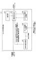
図1は、イントラ予測モード情報の符号化処理及び復号処理の概要を説明するための図である。 FIG. 1 is a diagram for explaining an outline of a coding process and a decoding process of intra prediction mode information.
処理対象のブロックに対して、イントラ予測を行う場合、符号化装置110では、第2のイントラ予測モードの番号(符号111)を選択する。第2のイントラ予測モードの番号(符号111)とは、参照方向を示す値であり、
・角度予測モードによるイントラ予測において、処理対象のブロックが参照可能な参照方向を示す番号のうちのいずれかの番号、または、
・直流予測モードを示す番号、または、
・プレーナ予測モードを示す番号、
のいずれかを指すものとする。When performing intra prediction for a block to be processed, the
-In the intra prediction by the angle prediction mode, one of the numbers indicating the reference direction that the block to be processed can refer to, or
-A number indicating the DC prediction mode, or
・ Planer prediction mode number,
It shall refer to any of.
なお、次世代の国際標準であるVVC規格では、処理対象のブロックが参照可能な参照方向として、87通りの参照方向が規定されている。 The VVC standard, which is the next-generation international standard, defines 87 reference directions as reference directions that can be referred to by the block to be processed.
続いて、符号化装置110では、処理対象のブロックが参照可能な参照方向を示す番号の総数が、87通りから67通りに削減されるように、処理対象のブロックの形状に応じて、第2のイントラ予測モードの番号(符号111)を変換する。これにより、符号化装置110では、変換後の番号(参照方向に応じた値)として、第1のイントラ予測モードの番号(符号112)を生成する。なお、以下の説明では、第1のイントラ予測モードの番号(符号112)と、第2のイントラ予測モードの番号(符号111)のいずれかを指す場合、単にイントラ予測モードの番号と称する場合がある。 Subsequently, in the
続いて、符号化装置110では、処理対象のブロックが参照可能な参照方向を示す番号の総数を、67通りから64通りにし、6ビットに収まるように、第1のイントラ予測モードの番号(符号112)を変換する。これにより、符号化装置110では、変換後の番号として、IntraLumaMPMRemainder(符号113)を得る。 Subsequently, in the
続いて、符号化装置110では、IntraLumaMPMRemainder(符号113)を二値化することで二値信号を生成する。また、符号化装置110では、生成した二値信号とMSB予測値(符号114)との排他的論理和を演算したうえで、算術符号化することで、イントラ予測モード情報の符号化ストリーム(符号117)を生成する。また、符号化装置110では、生成したイントラ予測モード情報の符号化ストリーム(符号117)を、復号装置120に送信する。 Subsequently, the
なお、MSB予測値(符号114)とは、IntraLumaMPMRemainderを二値化することで生成される二値信号の最上位ビット(MSB(Most Significant Bit))の予測値を指す。 The MSB predicted value (reference numeral 114) refers to the predicted value of the most significant bit (MSB (Most Significant Bit)) of the binary signal generated by binarizing the IntraLumaMPMReminder.
一方で、符号化装置110では、処理対象のブロックに隣接する処理済みのブロックに対してイントラ予測を行った際のイントラ予測モードの番号と同じイントラ予測モードの番号を用いて、処理対象のブロックに対してイントラ予測を行う場合がある。この場合、符号化装置110では、隣接する処理済みのブロックに対してイントラ予測を行った際のイントラ予測モードの番号と同じであることを示す情報を、イントラ予測モード情報とする。 On the other hand, in the
かかる情報をイントラ予測モード情報とするために、符号化装置110では、MPMリスト(符号115)を生成する。MPMリストとは、隣接するブロックに対してイントラ予測を行った際に用いた、イントラ予測モードの番号の一覧を指す。 In order to use such information as intra prediction mode information, the
続いて、符号化装置110では、IntraLumaMPMIdx(符号116)を生成する。IntraLumaMPMIdx(符号116)とは、処理対象のブロックに対してイントラ予測を行った際のイントラ予測モードの番号が、隣接ブロックに対してイントラ予測を行った際のいずれのイントラ予測モードの番号と同じであるかを示す情報を指す。 Subsequently, the
更に、符号化装置110では、IntraLumaMPMIdx(符号116)を二値化することで二値信号を生成し、算術符号化することで、イントラ予測モード情報の符号化ストリーム(符号117)を生成する。符号化装置110では、生成したイントラ予測モード情報の符号化ストリーム(符号117)を、復号装置120に送信する。 Further, the
このように、符号化装置110では、イントラ予測モード情報として、
・IntraLumaMPMRemainder(符号113)
・IntraLumaMPMIdx(符号116)
のいずれかを符号化する。As described above, in the
-IntraLumaMPMReminder (reference numeral 113)
-IntraLumaMPMIdx (reference numeral 116)
Encode any of the above.
また、符号化装置110では、イントラ予測モード情報として、
・いずれを符号化したかを示すIntraLumaMPMFlag
を符号化する。なお、IntraLumaMPMFlag=0とは、符号化装置110が、イントラ予測モード情報として、IntraLumaMPMRemainderを符号化したことを示す。また、IntraLumaMPMFlag=1とは、符号化装置110が、イントラ予測モード情報として、IntraLumaMPMIdxを符号化したことを示す。Further, in the
-IntraLumaMPMFlag indicating which was encoded
Is encoded. IntraLumaMPMFlag = 0 indicates that the
一方、復号装置120では、イントラ予測モード情報の符号化ストリーム(符号117)を受信すると、まず、当該符号化ストリームを復号し、復号したイントラ予測モード情報(符号121)を得る。 On the other hand, when the
続いて、復号装置120では、復号したイントラ予測モード情報(符号121)に含まれるIntraLumaMPMFlagを判定する。判定の結果、IntraLumaMPMFlagが0の場合、復号装置120では、復号したイントラ予測モード情報(符号121)に含まれる、IntraLumaMPMRemainderに応じた二値信号を取得する。 Subsequently, the
続いて、復号装置120では、取得したIntraLumaMPMRemainderに応じた二値信号とMSB予測値(符号122)との排他的論理和を演算したうえで、多値化する。これにより、復号装置120では、IntraLumaMPMRemainder(符号124)を生成する。 Subsequently, in the
続いて、復号装置120では、IntraLumaMPMRemainder(符号124)を7ビット化することで、67通りの第1のイントラ予測モードの番号のいずれかの番号を得る(符号125)。 Subsequently, the
一方、復号装置120では、復号したイントラ予測モード情報(符号121)に含まれるIntraLumaMPMFlagが1の場合には、復号したイントラ予測モード情報(符号121)に含まれる、IntraLumaMPMIdxの二値信号を取得する。 On the other hand, in the
続いて、復号装置120では、取得したIntraLumaMPMIdxの二値信号を多値化し、MPMリスト(符号123)より、第1のイントラ予測モードの番号(符号125)を得る。 Subsequently, in the
続いて、復号装置120では、第1のイントラ予測モードの番号(符号125)を、処理対象のブロックの形状に応じて、87通りの第2のイントラ予測モードの番号(符号126)のいずれかに振り直す。 Subsequently, in the
これにより、復号装置120では、87通りの参照方向のうちのいずれかの参照方向を示す第2のイントラ予測モードの番号(符号126)を得る。 As a result, the
このように、第1の実施形態に係る符号化装置110では、第2のイントラ予測モードの番号を、処理対象のブロックの形状に応じて変換することでIntraLumaMPMRemainderを得る。また、第1の実施形態に係る符号化装置110では、IntraLumaMPMRemainderの二値信号を符号化する際、MSB予測値を算出する。そして、二値信号のIntraLumaMPMRemainderの最上位ビットを、算出したMSB予測値(符号114)で置き換えることで、当該二値信号の最上位ビットの発生確率を上げる。 As described above, in the
これにより、符号化装置110では、IntraLumaMPMRemainder(符号113)の二値信号を算術符号化する際、最上位ビットについて、コンテキストモードによる算術符号化を実現する確率を上げることができる。この結果、符号化装置110によれば、バイパスモードによる算術符号化を行った場合と比べて、符号化時の符号量を削減することができる。 Thereby, in the
<符号化装置の機能構成>
次に、符号化装置110の機能構成について説明する。符号化装置110には符号化プログラムがインストールされており、当該プログラムが実行されることで、符号化装置110は、原画像として入力された動画像データを符号化し、符号化ストリームを復号装置120に送信する。<Functional configuration of coding device>
Next, the functional configuration of the
図2は、符号化装置の機能構成の一例を示す図である。図2に示すように、符号化装置110は、ブロック分割部201、直交変換部202、量子化部203、逆量子化部204、逆直交変換部205を有する。また、符号化装置110は、ループフィルタ部206、局所復号画像メモリ207、イントラ予測部208、インタ予測部209、エントロピ符号化部211を有する。 FIG. 2 is a diagram showing an example of the functional configuration of the coding apparatus. As shown in FIG. 2, the
ブロック分割部201は、入力された動画像データに含まれる各フレームを、複数のブロックに分割することで、原画ブロックを生成する。 The
直交変換部202は、ブロック分割部201において生成された原画ブロックと、後述する予測部(イントラ予測部208またはインタ予測部209)にて生成された予測ブロックとの差分である、予測誤差ブロックを取得する。また、直交変換部202は、取得した予測誤差ブロックに対して直交変換処理を行い、変換係数を算出する。 The orthogonal transformation unit 202 provides a prediction error block which is a difference between the original image block generated by the
量子化部203は、直交変換部202において算出された変換係数を量子化し、予測誤差符号化パラメータを算出する。 The
逆量子化部204は、量子化部203において算出された予測誤差符号化パラメータを逆量子化し、逆量子化変換係数を算出する。 The
逆直交変換部205は、逆量子化部204において算出された逆量子化変換係数に対して逆直交変換を行い、予測誤差復号ブロックを生成する。逆直交変換部205において生成された予測誤差復号ブロックに対しては、後述する予測部(イントラ予測部208またはインタ予測部209)にて生成された予測ブロックが加算されることで、加算部出力ブロックが生成される。 The inverse
ループフィルタ部206は、生成された加算部出力ブロックに対して、デブロッキングフィルタ等を用いてフィルタ処理を行うことで局所復号ブロックを生成し、局所復号画像メモリ207に格納する。 The
イントラ予測部208は変換部の一例であり、イントラ予測を行い、イントラ予測ブロックを生成する。なお、以下では、イントラ予測部208において、角度予測モードによるイントラ予測が行われるものとして説明する。 The
具体的には、イントラ予測部208は、原画ブロックのうちの処理対象のブロックにおいてイントラ予測を行う際、加算部出力ブロックのうちの処理対象のブロックの上側または左側に隣接するブロックを参照し、イントラ予測ブロックを生成する。 Specifically, the
また、イントラ予測部208は、処理対象のブロックについてのイントラ予測モード情報をエントロピ符号化部211に通知する。更に、イントラ予測部208は、処理対象のブロックに隣接する隣接ブロックの第1のイントラ予測モードの番号をエントロピ符号化部211に通知する。 Further, the
インタ予測部209は、原画ブロックのうちの処理対象のブロックについて、他のフレーム内の局所復号ブロックを用いてインタ予測を行い、インタ予測ブロックを生成する。 The
符号化装置110では、イントラ予測部208において生成されたイントラ予測ブロック、または、インタ予測部209において生成されたインタ予測ブロックのいずれか一方が選択される。 In the
選択された予測ブロックは、予測誤差復号ブロックに加算される。また、選択された予測ブロックは、原画ブロックのうちの処理対象のブロックとの差分の算出に用いられ、予測誤差ブロックとして、直交変換部202に入力される。なお、以下では、予測ブロックとしてイントラ予測ブロックが選択されるものとして説明する。 The selected prediction block is added to the prediction error decoding block. Further, the selected prediction block is used for calculating the difference from the block to be processed among the original image blocks, and is input to the orthogonal transformation unit 202 as a prediction error block. In the following, it is assumed that the intra prediction block is selected as the prediction block.
エントロピ符号化部211は、量子化部203において算出された予測誤差符号化パラメータを符号化する。また、エントロピ符号化部211は、イントラ予測部208より通知されたイントラ予測モード情報を含む各種シンタックス要素を符号化する。なお、エントロピ符号化部211は、イントラ予測モード情報を符号化するにあたり、隣接ブロックの第1のイントラ予測モードの番号を用いる。 The
このように、エントロピ符号化部211は、予測誤差符号化パラメータ及び各種シンタックス要素を符号化することで、符号化ストリームを生成し、復号装置120に送信する。 In this way, the
<符号化装置のハードウェア構成>
次に、符号化装置110のハードウェア構成について説明する。図3は、符号化装置のハードウェア構成の一例を示す図である。図3に示すように、符号化装置110は、CPU(Central Processing Unit)301、ROM(Read Only Memory)302、RAM(Random Access Memory)303を有する。CPU301、ROM302、RAM303は、いわゆるコンピュータを形成する。<Hardware configuration of encoding device>
Next, the hardware configuration of the
また、符号化装置110は、補助記憶装置304、表示装置305、操作装置306、I/F(Interface)装置307、ドライブ装置308を有する。なお、符号化装置110の各ハードウェアは、バス309を介して相互に接続されている。 Further, the
CPU301は、補助記憶装置304にインストールされている各種プログラム(例えば、符号化プログラム等)を実行する演算デバイスである。 The
ROM302は、不揮発性メモリである。ROM302は、補助記憶装置304にインストールされている各種プログラムをCPU301が実行するために必要な各種プログラム、データ等を格納する、主記憶デバイスとして機能する。具体的には、ROM302はBIOS(Basic Input/Output System)やEFI(Extensible Firmware Interface)等のブートプログラム等を格納する、主記憶デバイスとして機能する。
RAM303は、DRAM(Dynamic Random Access Memory)やSRAM(Static Random Access Memory)等の揮発性メモリである。RAM303は、補助記憶装置304にインストールされている各種プログラムがCPU301によって実行される際に展開される作業領域を提供する、主記憶デバイスとして機能する。 The
補助記憶装置304は、各種プログラムや、各種プログラムが実行される際に用いられるデータ(例えば、動画像データ)を格納する補助記憶デバイスである。 The
表示装置305は、符号化装置110の内部状態を表示する表示デバイスである。操作装置306は、符号化装置110のユーザが符号化装置110に対して各種指示を入力する入力デバイスである。 The
I/F装置307は、他の装置(例えば、復号装置120)と接続し、他の装置との間で符号化ストリームの送受信を行うための接続デバイスである。 The I /
ドライブ装置308は記録媒体310をセットするためのデバイスである。ここでいう記録媒体310には、CD-ROM、フレキシブルディスク、光磁気ディスク等のように情報を光学的、電気的あるいは磁気的に記録する媒体が含まれる。また、記録媒体310には、ROM、フラッシュメモリ等のように情報を電気的に記録する半導体メモリ等が含まれていてもよい。 The
なお、補助記憶装置304にインストールされる各種プログラムは、例えば、配布された記録媒体310がドライブ装置308にセットされ、該記録媒体310に記録された各種プログラムがドライブ装置308により読み出されることでインストールされる。あるいは、補助記憶装置304にインストールされる各種プログラムは、不図示のネットワークよりダウンロードされることでインストールされてもよい。 The various programs installed in the
なお、説明の簡略化のため、図3では、符号化装置110のハードウェア構成のみを示したが、復号装置120も同様のハードウェア構成を有しているものとする。 Although only the hardware configuration of the
<VVC規格のイントラ予測に関する規定>
次に、次世代の国際標準であるVVC規格のイントラ予測に関する規定として、処理対象のブロック、イントラ予測モードの番号、IntraLumaMPMRemainderに関する規定について説明する。<Rules for intra-prediction of VVC standard>
Next, as the provisions regarding the intra-prediction of the VVC standard, which is the next-generation international standard, the regulations regarding the block to be processed, the number of the intra-prediction mode, and the IntraLumaMPMReminder will be described.
(1)処理対象のブロックに関する規定
はじめに、VVC規格のイントラ予測に関する規定のうち、処理対象のブロックに関する規定について説明する。図4は、VVC規格のイントラ予測において用いられる処理対象のブロックの一例を示す図である。HEVC規格のイントラ予測では、処理対象のブロックとして、形状が正方形のみのブロックが用いられていたが、VVC規格の場合、図4に示すように長方形のブロックも用いられる。(1) Regulations regarding blocks to be processed First, among the regulations regarding intra-prediction of the VVC standard, the regulations regarding blocks to be processed will be described. FIG. 4 is a diagram showing an example of a block to be processed used in the intra prediction of the VVC standard. In the intra-prediction of the HEVC standard, a block having only a square shape was used as the block to be processed, but in the case of the VVC standard, a rectangular block is also used as shown in FIG.
図4において、フレーム400は、VVC規格のイントラ予測において用いられる各種ブロックの形状、サイズを示しており、符号410~430は、このうちの典型的なブロックの形状、サイズを抜粋して示したものである。 In FIG. 4, the
このうち、符号410は、横方向画素数=W、縦方向画素数=Hのブロックを、横方向画素数=(W/2)、縦方向画素数=(H/2)の4つのブロックに分割することで得られたブロックを示している。 Of these,
また、符号420は、横方向画素数=W、縦方向画素数=Hのブロックを、横方向画素数=(W/2)、縦方向画素数=Hの2つのブロック、または、横方向画素数=W、縦方向画素数=(H/2)の2つのブロックに分割することで得られたブロックを示している。 Further,
また、符号430は、横方向画素数=W、縦方向画素数=Hのブロックを、横方向画素数=(W/4)、縦方向画素数=Hの2つのブロックと、横方向画素数=(W/2)、縦方向画素数=Hの1つのブロックとに分割することで得られたブロックを示している。あるいは、符号430は、横方向画素数=W、縦方向画素数=Hのブロックを、横方向画素数=W、縦方向画素数=(H/4)の2つのブロックと、横方向画素数=W、縦方向画素数=(H/2)の1つのブロックとに分割することで得られたブロックを示している。 Further,
このように、VVC規格では、様々な形状及びサイズの長方形のブロックが用いられる。なお、図4の例では、長方形のブロックの縦横比が1:2の場合と、2:1の場合とについて示したが、1:2または2:1以外の縦横比の長方形のブロックが用いられてもよい。 Thus, the VVC standard uses rectangular blocks of various shapes and sizes. In the example of FIG. 4, the case where the aspect ratio of the rectangular block is 1: 2 and the case where the aspect ratio is 2: 1 are shown, but a rectangular block having an aspect ratio other than 1: 2 or 2: 1 is used. May be done.
(2)イントラ予測モードの番号に関する規定
次に、VVC規格のイントラ予測に関する規定のうち、イントラ予測モードの番号に関する規定について、HEVC規格のイントラ予測モードの番号に関する規定と対比しながら説明する。(2) Provisions regarding intra-prediction mode numbers Next, among the provisions regarding intra-prediction of the VVC standard, the provisions regarding intra-prediction mode numbers will be described in comparison with the provisions regarding intra-prediction mode numbers of the HEVC standard.
(2-1)HEVC規格の場合
図5は、HEVC規格において規定されたイントラ予測の参照方向及びイントラ予測モードの番号を示す図である。(2-1) In the case of the HEVC standard FIG. 5 is a diagram showing the reference direction of the intra prediction and the number of the intra prediction mode specified in the HEVC standard.
イントラ予測は、ラスタスキャン順で先に処理されたブロック(加算部出力ブロック)の画素値を予測画素値とする。このため、参照方向は、図5に示すように、フレーム内の左下方向から右上方向までの時計回りの範囲(左水平方向を0°とした場合、-45°~+135°の範囲)となる。 In the intra prediction, the pixel value of the block (adder output block) processed first in the raster scan order is used as the predicted pixel value. Therefore, as shown in FIG. 5, the reference direction is a clockwise range from the lower left direction to the upper right direction in the frame (when the left horizontal direction is 0 °, the range is −45 ° to + 135 °). ..
また、図5に示すように、各角度には、-45°から+135°の順で、2番から34番までの33通りの角度予測モードによるイントラ予測モードの番号が割り当てられている。なお、0番及び1番には、それぞれ、プレーナ予測モード及び直流予測モード(空間的な方向性をもたない予測モード)によるイントラ予測モードの番号が割り当てられている。 Further, as shown in FIG. 5, each angle is assigned an intra prediction mode number according to 33 different angle prediction modes from No. 2 to No. 34 in the order of −45 ° to + 135 °. The
角度予測モードによるイントラ予測モードでは、33通りの参照方向のうち、指定された参照方向に合致した外挿を行うことで、処理対象のブロックの各画素の予測画素値を生成する。 In the intra prediction mode by the angle prediction mode, the predicted pixel value of each pixel of the block to be processed is generated by performing extrapolation that matches the designated reference direction among the 33 reference directions.
(2-2)VVC規格の場合の参照方向
一方、図6は、VVC規格において規定されたイントラ予測の参照方向を示す図である。VVC規格の場合、HEVC規格と比較して、参照方向の数が2倍となる。また、VVC規格の場合、処理対象のブロックが非正方形である場合を考慮して、参照方向の範囲が追加されている(-73°~-45°、及び、+135°~+163°が追加されている)。(2-2) Reference direction in the case of the VVC standard On the other hand, FIG. 6 is a diagram showing a reference direction of the intra prediction specified in the VVC standard. In the case of the VVC standard, the number of reference directions is doubled as compared with the HEVC standard. Further, in the case of the VVC standard, a range in the reference direction is added (-73 ° to -45 ° and + 135 ° to + 136 °) in consideration of the case where the block to be processed is non-square. ing).
図6において、符号601は、処理対象のブロックが正方形である場合の参照方向である、-45°~+45°の範囲を示している。また、符号602は、処理対象のブロックが正方形である場合の参照方向である、+45°~+135°の範囲を示している。 In FIG. 6,
一方、符号603は、処理対象のブロックが非正方形である場合の参照方向として追加された、-73°~-45°の範囲を示している。更に、符号604は、処理対象のブロックが非正方形である場合の参照方向として追加された、+135°~+163°の範囲を示している。 On the other hand,
なお、VVC規格の場合、第2のイントラ予測モードの番号の総数は、85通りの参照方向を有する角度予測モードの番号に、プレーナ予測モード及び直流予測モードの番号を加えた87通りとなる。 In the case of the VVC standard, the total number of the numbers of the second intra prediction mode is 87, which is the number of the angle prediction mode having 85 reference directions plus the number of the planar prediction mode and the DC prediction mode.
(2-3)第2のイントラ予測モードの番号
次に、VVC規格において規定された、87通りの参照方向を有する角度予測モード、プレーナ予測モード及び直流予測モードを含む、第2のイントラ予測モードの番号の割り当てについて説明する。図7は、VVC規格において規定された第2のイントラ予測モードの番号を説明するための図である、
図7に示すように、-45°から+135°の順で、2番から66番までの角度予測モードによる第2のイントラ予測モードの番号が割り当てられる。なお、0番及び1番には、それぞれ、プレーナ予測モード及び直流予測モードによる第2のイントラ予測モードの番号が割り当てられる。(2-3) Number of second intra prediction mode Next, a second intra prediction mode including an angle prediction mode having 87 reference directions, a planar prediction mode, and a DC prediction mode specified in the VVC standard. The assignment of numbers will be described. FIG. 7 is a diagram for explaining the number of the second intra prediction mode specified in the VVC standard.
As shown in FIG. 7, the number of the second intra prediction mode by the angle prediction mode from No. 2 to No. 66 is assigned in the order of −45 ° to + 135 °. The
加えて、+135°以上の各角度には、67番から76番までの角度予測モードによる第2のイントラ予測モードの番号が割り当てられる。また、-73°から-45°までの各角度には、-10番から-1番までの角度予測モードによる第2のイントラ予測モードの番号が割り当てられる。 In addition, each angle of + 135 ° or more is assigned a number of a second intra prediction mode according to the angle prediction modes of 67 to 76. Further, each angle from −73 ° to −45 ° is assigned a number of a second intra prediction mode according to the angle prediction mode from −10 to −1.
(2-4)第1のイントラ予測モードの番号
ここで、VVC規格では、図1を用いて説明したとおり、87通りの第2のイントラ予測モードの番号(符号111)を、67通りの第1のイントラ予測モードの番号(符号112)へと、総数を削減する。(2-4) Numbers of First Intra Prediction Mode Here, in the VVC standard, as described with reference to FIG. 1, 87 second intra prediction mode numbers (reference numeral 111) are used in 67 different ways. The total number is reduced to the number (reference numeral 112) of the intra prediction mode of 1.
これは、イントラ予測モードの番号の総数を87通りとすることで、HEVC規格と比較して、予測誤差を低減できる一方で、符号化した際のイントラ予測モード情報の符号量が増加することを考慮したものである。 This is because by setting the total number of intra prediction mode numbers to 87, the prediction error can be reduced as compared with the HEVC standard, but the amount of code of the intra prediction mode information when encoded increases. It is a consideration.
図8は、イントラ予測モードの番号の総数を削減する方法を説明するための図である。図8において、処理対象のブロック801は、横方向画素数=W、縦方向画素数=(W/2)であるとする。また、画素802は、処理対象のブロック801の最も右下に位置する画素であり、画素803は、処理対象のブロック801に隣接し、角度予測モードによるイントラ予測の際に参照される画素である。 FIG. 8 is a diagram for explaining a method of reducing the total number of intra prediction mode numbers. In FIG. 8, it is assumed that the
また、矢印810、811、820、821は、それぞれ、画素802に対する、-45°、-30°、+135°、+150°の参照方向を示している。そして、矢印810、811、820、821の先端に位置する画素は、画素802によって参照される画素を示している。つまり、矢印810、811、820、821の先端に位置する画素の画素値は、画素802の予測画素値である。 Further,
一般に、角度予測モードによるイントラ予測の予測性能は、予測対象となる画素(ここでは、画素802)と、参照画素(ここでは、矢印810、811、820、821の先端に位置する画素)との間の距離に反比例する。つまり、予測対象となる画素と、参照画素との間の距離が近いほど予測誤差は小さくなり、符号化効率が向上する。 In general, the prediction performance of intra-prediction by the angle prediction mode is that of a pixel to be predicted (here, pixel 802) and a reference pixel (here, a pixel located at the tip of
図8の例では、-45°の参照方向の場合、参照画素(矢印810の先端に位置する画素)までの距離は、その対角線上にある+135°の参照方向の場合の、参照画素(矢印820の先端に位置する画素)までの距離と比べて、大きくなる。 In the example of FIG. 8, the distance to the reference pixel (the pixel located at the tip of the arrow 810) in the reference direction of −45 ° is the reference pixel (arrow) in the reference direction of + 135 ° on the diagonal line thereof. It is larger than the distance to the pixel located at the tip of the 820).
なお、処理対象のブロックの形状が正方形であった場合には、両者の距離は等しくなる。一方で、処理対象のブロックの形状が図8に示す長方形であった場合、同一線上にある角度で、画素802と参照画素との距離が等しくなるのは、-30°の参照方向と+150°の参照方向の場合である。 If the shape of the block to be processed is square, the distance between the two is equal. On the other hand, when the shape of the block to be processed is the rectangle shown in FIG. 8, the distance between the
つまり、処理対象のブロックの縦横比が1:2の場合、角度が-30°~-45°の範囲の参照方向は、角度予測モードによるイントラ予測の予測性能が低く、実際に選択される確率が低いといえる。例えば、処理対象のブロックの周囲に均一なテクスチャがあり、その方向が、矢印810及び矢印820と平行であった場合、矢印810の参照方向の代わりに、矢印820の参照方向を選択することで、予測効率を向上させることが期待できる。 That is, when the aspect ratio of the block to be processed is 1: 2, the reference direction in the range of -30 ° to -45 ° has low prediction performance of intra prediction by the angle prediction mode, and the probability of being actually selected. Can be said to be low. For example, if there is a uniform texture around the block to be processed and its direction is parallel to
VVC規格では、このことを利用して、イントラ予測モードの番号の総数が67通りとなるように(HEVC規格と同じになるように)、イントラ予測モードの番号を振り直す。 In the VVC standard, this is used to renumber the intra prediction mode so that the total number of intra prediction mode numbers is 67 (same as the HEVC standard).
つまり、イントラ予測において選択された参照方向が、
・180°反転した場合でもイントラ予測が可能、かつ、
・選択された参照方向における参照画素までの距離が、180°反転した場合の参照画素までの距離よりも小さい、
場合には、180°反転した参照方向を示す値が用いられることになる。That is, the reference direction selected in the intra prediction is
・ Intra prediction is possible even when flipped 180 °, and
The distance to the reference pixel in the selected reference direction is smaller than the distance to the reference pixel when inverted by 180 °.
In that case, a value indicating a reference direction inverted by 180 ° will be used.
このようにして、VVC規格では、87通りの第2のイントラ予測モードの番号(符号111)を、67通りの第1のイントラ予測モードの番号(符号112)へと変換し、総数を削減する。 In this way, in the VVC standard, 87 second intra prediction mode numbers (reference numeral 111) are converted into 67 first intra prediction mode numbers (reference numeral 112), and the total number is reduced. ..
(2-5)総数削減処理の具体例
ここで、第2のイントラ予測モードの番号の総数を削減する処理の具体例を、図6を参照しながら説明する。(2-5) Specific Example of Total Number Reduction Process Here, a specific example of the process of reducing the total number of numbers in the second intra prediction mode will be described with reference to FIG.
VVC規格の場合、処理対象のブロックの横方向画素数と縦方向画素数とに基づいて、処理対象のブロックが横長のブロックであるのか、縦長のブロックであるのかを判定する。 In the case of the VVC standard, it is determined whether the block to be processed is a horizontally long block or a vertically long block based on the number of horizontal pixels and the number of vertical pixels of the block to be processed.
そして、横長のブロックであると判定した場合、VVC規格では、符号604で示した参照方向を、180°反転させた角度(符号601の最下から順に上側の10方向)を特定する。また、VVC規格では、特定した10方向の参照方向については使用せず、これら10方向の第2のイントラ予測モードの番号を、符号604で示した参照方向に対応する第1のイントラ予測モードの番号に振り直す。具体的には、VVC規格では、第2のイントラ予測モードの番号が2~11の場合、65を加算して、67~76に変換する。 When it is determined that the block is horizontally long, the VVC standard specifies an angle obtained by reversing the reference direction indicated by
一方、縦長のブロックであると判定した場合、VVC規格では、符号603で示した参照方向を、180°反転させた角度(符号602の最右から順に左側の10方向)を特定する。また、VVC規格では、特定した10方向の参照方向については使用せず、これら10方向の第2のイントラ予測モードの番号を、符号602で示した参照方向に対応する第1のイントラ予測モードの番号に振り直す。具体的には、VVC規格では、第2のイントラ予測モードの番号が57~66の場合、67を減算して-10~-1に変換する。 On the other hand, when it is determined that the block is vertically long, the VVC standard specifies an angle obtained by reversing the reference direction indicated by
なお、上記以外であると判定した場合、VVC規格では第2のイントラ予測モードの番号を変換しない。このため、第1のイントラ予測モードの番号は、第2のイントラ予測モードの番号と同じとなる。例えば、第2のイントラ予測モードの番号が12~56の場合には、第1のイントラ予測モードの番号は12~56となる。 If it is determined to be other than the above, the number of the second intra prediction mode is not converted in the VVC standard. Therefore, the number of the first intra prediction mode is the same as the number of the second intra prediction mode. For example, when the number of the second intra prediction mode is 12 to 56, the number of the first intra prediction mode is 12 to 56.
以上のとおり、VVC規格において、イントラ予測モードの番号の総数を削減し、第2のイントラ予測モードの番号を、第1のイントラ予測モードの番号に変換するための処理は、下記のように整理することができる。なお、下記において、M1は、第1のイントラ予測モードの番号を表し、M2は、第2のイントラ予測モードの番号を表しているものとする。
・横方向画素数(W)=縦方向画素数(H)の場合
M1=M2
・横方向画素数(W)=縦方向画素数(H)の場合
2≦M2<mLの場合、M1=M2+65
ただし、W=2Hの場合には、mL=8、W>2Hの場合には、mL=12
それ以外の場合には、M1=M2
・横方向画素数(W)<縦方向画素数(H)の場合
mH<M2≦66の場合、M1=M2-67
ただし、H=2Wの場合、mH=60、H>2Wの場合、mH=56
それ以外の場合、M1=M2
これにより、VVC規格では、第2のイントラ予測モードの番号(M2)を、第1のイントラ予測モードの番号(M1)に変換することができる。As described above, in the VVC standard, the process for reducing the total number of intra-prediction mode numbers and converting the second intra-prediction mode number to the first intra-prediction mode number is organized as follows. can do. In the following, it is assumed that M1 represents the number of the first intra prediction mode and M2 represents the number of the second intra prediction mode.
-When the number of pixels in the horizontal direction (W) = the number of pixels in the vertical direction (H) M1 = M2
When the number of pixels in the horizontal direction (W) = the number of pixels in the vertical direction (H), when 2 ≦ M2 <mL, M1 = M2 + 65.
However, when W = 2H, mL = 8, and when W> 2H, mL = 12
Otherwise, M1 = M2
When the number of pixels in the horizontal direction (W) <the number of pixels in the vertical direction (H), when mH <M2 ≦ 66, M1 = M2-67.
However, when H = 2W, mH = 60, and when H> 2W, mH = 56.
Otherwise, M1 = M2
Thereby, in the VVC standard, the number (M2) of the second intra prediction mode can be converted into the number (M1) of the first intra prediction mode.
(3)IntraLumaMPMRemainderの説明
次に、第1のイントラ予測モードの番号の総数(67通り)を、6ビット化し、IntraLumaMPMRemainder(符号113)を導出する処理について説明する。ここでは、第1のイントラ予測モードの番号(符号112)をIntraDirとおく。(3) Explanation of IntraLumaMPMReminder Next, a process of deriving the IntraLumaMPMReminder (reference numeral 113) by converting the total number of numbers (67 ways) of the first intra prediction mode into 6 bits will be described. Here, the number (reference numeral 112) of the first intra prediction mode is referred to as IntraDir.
VVC規格によれば、以下の手順により、IntraLumaMPMRemainderを導出することができる。 According to the VVC standard, the IntraLumaMPMReminder can be derived by the following procedure.
i)はじめに、IntraLumaMPMRemainder=IntraDirとおく。 i) First, let IntraLumaMPMReminder = IntraDir.
ii)続いて、MPM(Most Probable Mode)の各エントリについて昇順でソートし、mpm_sort[i](i=0..2,mpm_sort[0]<mpm_sort[1]<mpm_sort[2])を得る。 ii) Subsequently, each entry of MPM (Most Probable Mode) is sorted in ascending order to obtain mpm_sort [i] (i = 0.2, mpm_sort [0] <mpm_sort [1] <mpm_sort [2]).
iii)続いて、mpm_sort[i]と、IntraLumaMPMRemainderとを順に比較する。 iii) Subsequently, mpm_sort [i] and IntraLumaMPMReminder are compared in order.
iv)比較の結果、mpm_sort[i]<=IntraLumaMPMRemainderが成立する場合には、IntraLumaMPMRemainderを1減算する。 iv) As a result of comparison, if mpm_sort [i] <= IntraLumaMPMReminder is established, IntraLumaMPMReminder is subtracted by 1.
これにより、VVC規格によれば、第1のイントラ予測モードの番号(符号112)に基づいて、IntraLumaMPMRemainderを導出することができる。なお、上記手順により導出される最終的なIntraLumaMPMRemainderは、第1のイントラ予測モードの番号(符号113)より、最大で"3"小さくなる。 Thereby, according to the VVC standard, the IntraLumaMPMReminder can be derived based on the number (reference numeral 112) of the first intra prediction mode. The final IntraLumaMPMReminder derived by the above procedure is at most "3" smaller than the number (reference numeral 113) of the first intra prediction mode.
<イントラ予測部の機能構成>
次に、符号化装置110のイントラ予測部208の機能構成について説明する。図9は、符号化装置のイントラ予測部の機能構成の一例を示す図である。図9に示すように、イントラ予測部208は、制御部901、第2の予測モード算出部902、フィルタ部903、コスト算出部904、予測モード保持部905、MPM生成部906を有する。<Functional configuration of the intra prediction unit>
Next, the functional configuration of the
制御部901は、処理対象のブロックについてイントラ予測モード情報を選択する。具体的には、制御部901では、コスト評価の対象となる第1のイントラ予測モードの番号を、順次、第2の予測モード算出部902に通知する。また、制御部901では、処理対象のブロックの横方向画素数(W)及び縦方向画素数(H)を、第2の予測モード算出部902に通知する。 The control unit 901 selects the intra prediction mode information for the block to be processed. Specifically, the control unit 901 sequentially notifies the second prediction
また、制御部901では、コスト算出部904で算出された符号化コストが、最小となる第1のイントラ予測モードの番号について、IntraLumaMPMRemainderを算出する。 Further, the control unit 901 calculates the IntraLumaMPMReminder for the number of the first intra prediction mode in which the coding cost calculated by the
あるいは、制御部901では、コスト算出部904で算出された符号化コストが、最小となる第1のイントラ予測モードの番号に対応する第2のイントラ予測モードの番号を特定し、MPM生成部906により生成されたMPMリストを参照する。そして、制御部901では、特定した第2のイントラ予測モードの番号が、MPMリスト内の、処理対象のブロックに隣接するブロックについてイントラ予測された際の第2のイントラ予測モードの番号と一致するかを判定する。更に、制御部901では、一致すると判定した場合、当該MPMリスト内において、当該第2のイントラ予測モードの番号を特定するためのIntraLumaMPMIdxを生成する。 Alternatively, the control unit 901 specifies the number of the second intra prediction mode corresponding to the number of the first intra prediction mode in which the coding cost calculated by the
このようにして、制御部901では、
・IntraLumaMPMFlag、
・IntraLumaMPMIdx、または、IntraLumaMPMRemainderのいずれか、
が含まれるイントラ予測モード情報を選択する。In this way, in the control unit 901,
・ IntraLumaMPMFlag,
-Either IntraLumaMPMIdx or IntraLumaMPMReminder,
Select the intra prediction mode information that contains.
また、制御部901は、選択したイントラ予測モード情報を、エントロピ符号化部211に通知する。なお、制御部901では、IntraLumaMPMIdxを通知する場合、IntraLumaMPMFlag=1に設定し、IntraLumaMPMRemainderを通知する場合、IntraLumaMPMFlag=0に設定する。 Further, the control unit 901 notifies the
また、制御部901は、処理対象のブロックに隣接するブロックについてイントラ予測された際の第2のイントラ予測モードの番号を、MPMリストより取得し、第1のイントラ予測モードの番号に変換する。これにより、制御部901は、隣接するブロックの第1のイントラ予測モードの番号を取得する。また、制御部901は、隣接するブロックの第1のイントラ予測モードの番号を、エントロピ符号化部211に通知する。 Further, the control unit 901 acquires the number of the second intra prediction mode when the block adjacent to the block to be processed is intra-predicted from the MPM list and converts it into the number of the first intra prediction mode. As a result, the control unit 901 acquires the number of the first intra prediction mode of the adjacent block. Further, the control unit 901 notifies the
第2の予測モード算出部902は、制御部901から通知された、コスト評価の対象となる第1のイントラ予測モードの番号を、処理対象のブロックの横方向画素数(W)と縦方向画素数(H)とに基づいて、第2のイントラ予測モードの番号に変換する。また、第2の予測モード算出部902は、第2のイントラ予測モードの番号を、フィルタ部903に通知する。 The second prediction
フィルタ部903は、加算部出力ブロックのうちの処理対象のブロックに隣接するブロックの画素値について、第2のイントラ予測モードの番号に対応する参照方向に基づきフィルタ演算を行い、予測画素値を算出する。また、フィルタ部903は、符号化コストが最小となる第2のイントラ予測モードの番号に対応する参照方向に基づきフィルタ演算を行った際の予測画素値を、イントラ予測ブロックとして出力する。 The
コスト算出部904は、原画ブロックのうちの処理対象のブロックから、フィルタ部903にてフィルタ演算された予測画素値を減算し、符号化コストを算出する。コスト算出部904では、符号化コストを、歪み量(予測誤差の強度)と、量子化値に比例して増加する重みを該量子化値に乗算したデータ量と、を和算することで算出する。また、コスト算出部904では、当該データ量を、予測誤差を仮想的に符号化した際の発生データ量と、エントロピ符号化部211に出力するイントラ予測モード情報のデータ量とを和算することで算出する。 The
なお、コスト算出部904では、イントラ予測モード情報にIntraLumaMPMRemainderが含まれる場合、
・IntraLumaMPMRemainderのデータ量を、固定の6ビットとして符号化コストを算出する。あるいは、
・IntraLumaMPMRemainderの二値信号の最上位ビットとMSB予測値との排他的論理和が0となる発生確率のエントロピに基づいて算出したビット量を、データ量として符号化コストを算出する。In the
-The coding cost is calculated with the data amount of IntraLumaMPMReminder as a fixed 6 bits. or,
The coding cost is calculated using the bit amount calculated based on the entropy of the occurrence probability that the exclusive OR of the most significant bit of the binary signal of the IntraLumaMPMReminder and the MSB predicted value becomes 0 as the data amount.
このとき、排他的論理和が0となる発生確率は、エントロピ符号化部211が、直前の処理対象のブロックについて算出した発生確率を用いてもよい。あるいは、エントロピ符号化部211が、直前のピクチャの最終ブロックについて算出した発生確率を用いてもよい。 At this time, as the probability of occurrence that the exclusive OR becomes 0, the probability of occurrence calculated by the
更に、コスト算出部904は、算出した符号化コストが、すでに算出済みの符号化コストよりも小さいか否かを判定する。すでに算出済みの符号化コストよりも小さいと判定した場合、コスト算出部904は、判定結果及び符号化コストを制御部901に通知する。これにより、制御部901は、対応する第1のイントラ予測モードの番号及び符号化コストを、予測モード保持部905に通知する。 Further, the
なお、コスト算出部904が、全ての第1のイントラ予測モードの番号について符号化コストを算出することで、制御部901では、イントラ予測モード情報を選択することができる。 The
予測モード保持部905は、制御部901から通知される、第1のイントラ予測モードの番号に対応する第2のイントラ予測モードの番号を保持する。なお、処理対象のブロックに対して、イントラ予測が行われなかった場合、予測モード保持部905では、直流予測モードを示す番号を保持する。 The prediction
また、予測モード保持部905は、保持した第2のイントラ予測モードの番号を、MPM生成部906に対して、処理済みの隣接ブロックの第2のイントラ予測モードの番号として出力する。 Further, the prediction
MPM生成部906は、処理対象のブロックに隣接するブロックについてイントラ予測された際の第2のイントラ予測モードの番号を、制御部901に提供する。また、MPM生成部906は、予測モード保持部905から、処理済みの隣接ブロックの第2のイントラ予測モードの番号を、次の処理対象のブロックの隣接ブロックの第2のイントラ予測モードの番号として、MPMリストに登録する。 The
<イントラ予測部によるイントラ予測処理の流れ>
次に、イントラ予測部208によるイントラ予測処理の流れについて説明する。図10は、イントラ予測部によるイントラ予測処理の流れを示すフローチャートである。<Flow of intra prediction processing by the intra prediction unit>
Next, the flow of the intra prediction process by the
ステップS1001において、イントラ予測部208は、初期化を行う。具体的には、制御部901は、コスト評価の対象となる第1のイントラ予測モードの番号を"0"にする。また、MPM生成部906は、MPMリストを生成する。更に、予測モード保持部905は、最小コストCmに、取り得る最大値(例えば、232-1)を設定する。In step S1001, the
ステップS1002において、第2の予測モード算出部902は、制御部901より出力された第1のイントラ予測モードの番号を、第2のイントラ予測モードの番号に変換する。 In step S1002, the second prediction
ステップS1003において、フィルタ部903は、第2のイントラ予測モードの番号に対応する参照方向に位置する加算部出力ブロックを参照し、予測画素値を生成する。また、コスト算出部904は、原画ブロックのうちの処理対象のブロックと生成した予測画素値との残差と、第1のイントラ予測モードの番号に対応するIntraLumaMPMRemainderのデータ量とに従い、符号化コストCtを算出する。 In step S1003, the
ステップS1004において、予測モード保持部905は、符号化コストCtが最小コストCmよりも小さいか否かを判定する。ステップS1004において、符号化コストCtが最小コストCmよりも小さいと判定された場合には(ステップS1004においてYesの場合には)、ステップS1005に進む。 In step S1004, the prediction
ステップS1005において、予測モード保持部905は、第1のイントラ予測モードの番号に対応する、第2のイントラ予測モードの番号を保持する。また、予測モード保持部905は、符号化コストCtを最小コストCmにセットし、予測画素値を保持する。 In step S1005, the prediction
一方、ステップS1004において、符号化コストCtが最小コストCm以上であると判定した場合には(ステップS1004においてNoの場合には)、ステップS1006に進む。 On the other hand, if it is determined in step S1004 that the coding cost Ct is equal to or greater than the minimum cost Cm (No in step S1004), the process proceeds to step S1006.
ステップS1006において、制御部901は、第1のイントラ予測モードの番号が取り得る最大値(=66)未満であるか否かを判定する。ステップS1006において、イントラ予測モードの番号が最大値未満であると判定した場合(ステップS1006においてYesの場合)、制御部901は、コスト評価の対象となっていない第1のイントラ予測モードの番号が残っていると判定する。この場合、制御部901は、ステップS1007に進む。 In step S1006, the control unit 901 determines whether or not the number of the first intra prediction mode is less than the maximum possible value (= 66). If it is determined in step S1006 that the number of the intra prediction mode is less than the maximum value (Yes in step S1006), the control unit 901 determines that the number of the first intra prediction mode that is not the target of cost evaluation is Judge that it remains. In this case, the control unit 901 proceeds to step S1007.
ステップS1007において、制御部901は、第1のイントラ予測モードの番号をインクリメントした後、ステップS1002に戻る。 In step S1007, the control unit 901 returns to step S1002 after incrementing the number of the first intra prediction mode.
一方、ステップS1006において、第1のイントラ予測モードの番号が最大値以上であると判定した場合(ステップS1006においてNoの場合)、制御部901は、第1のイントラ予測モードの番号全てについて、コスト評価の対象となったと判定する。この場合、制御部901は、ステップS1008に進む。 On the other hand, when it is determined in step S1006 that the number of the first intra prediction mode is equal to or greater than the maximum value (No in step S1006), the control unit 901 costs for all the numbers of the first intra prediction mode. Judge that it was the target of evaluation. In this case, the control unit 901 proceeds to step S1008.
ステップS1008において、フィルタ部903は、予測モード保持部905に保持されている予測画素値を、イントラ予測ブロックとして出力する。 In step S1008, the
また、制御部901は、予測モード保持部905に保持されている、第2のイントラ予測モードの番号に基づいて、第1のイントラ予測モードの番号を算出し、更に、IntraLumaMPMRemainderを生成する。 Further, the control unit 901 calculates the number of the first intra prediction mode based on the number of the second intra prediction mode held in the prediction
また、制御部901は、予測モード保持部905に保持されている、第2のイントラ予測モードの番号に基づいて、MPMリストを参照する。そして、制御部901は、処理対象のブロックに隣接するブロックについてイントラ予測された際の第2のイントラ予測モードの番号と一致する場合には、IntraLumaMPMIdxを生成する。 Further, the control unit 901 refers to the MPM list based on the number of the second intra prediction mode held in the prediction
更に、制御部901は、IntraLumaMPMRemainder(またはIntraLumaMPMIdx)と、IntraLumaMPMFlagとを、イントラ予測モード情報として、エントロピ符号化部211に出力する。 Further, the control unit 901 outputs the IntraLumaMPMReminder (or IntraLumaMPMIdx) and the IntraLumaMPMFlag to the
<エントロピ符号化部の機能構成>
次に、符号化装置110のエントロピ符号化部211の機能構成について説明する。図11は、符号化装置のエントロピ符号化部の機能構成の一例を示す図である。図11に示すように、エントロピ符号化部211は、二値化部1101、算術符号化部1102、コンテキスト保持・計算部1103、モード予測値生成部1104、符号化値生成部1105を有する。<Functional configuration of the entropy coding unit>
Next, the functional configuration of the
算術符号化部1102は符号化部の一例であり、処理対象のブロックについての予測誤差符号化パラメータ、処理対象のブロックの符号化パラメータ(ここでは、イントラ予測モード情報)、及び、ピクチャの符号化パラメータを、符号化対象として取得する。また、算術符号化部1102は、取得した符号化対象を、コンテキストを使った二値算術符号化方式でエントロピ符号化する。 The
二値化部1101は、符号化対象のうち、シンタックス要素について二値信号を生成する。二値化部1101は、例えば、イントラ予測部208より通知された、イントラ予測モード情報の二値信号を生成する。 The
コンテキスト保持・計算部1103は、エントロピ符号化した各シンタックス要素の二値信号を保存し、処理対象のブロックのシンタックス要素のコンテキスト値(MPS(Most Probable Symbol)とその発生確率)を算出し、更新する。 The context holding /
例えば、コンテキスト保持・計算部1103は、処理対象のブロックに対応するIntraLumaMPMRemainderの二値信号の各ビットについて、MPSとその発生確率を算出し、保存する。 For example, the context holding / calculating
モード予測値生成部1104は算出部の一例であり、イントラ予測部208から、隣接ブロックの第1のイントラ予測モードの番号が通知されると、該第1のイントラ予測モードの番号を保存する。また、モード予測値生成部1104は、隣接ブロックの第1のイントラ予測モードの番号に基づいて、処理対象のブロックのIntraLumaMPMRemainderの二値信号の最上位ビットの予測値を算出する。更に、モード予測値生成部1104は、算出した最上位ビットの予測値(MSB(Most Significant Bit)予測値)を、符号化値生成部1105に通知する。 The mode prediction
符号化値生成部1105は生成部の一例であり、二値化部1101において生成されたイントラ予測モード情報の二値信号のうち、IntraLumaMPMRemainderの二値信号を取得する。また、符号化値生成部1105は、IntraLumaMPMRemainderの二値信号の各ビットのうち、最上位ビットについて、モード予測値生成部1104にて算出されたMSB予測値との排他的論理和を演算する。また、符号化値生成部1105は、排他的論理和を演算したIntraLumaMPMRemainderの二値信号(算術符号化のための二値信号)を算術符号化部1102に通知する。 The coded
これにより、算術符号化部1102では、IntraLumaMPMRemainderについて二値算術符号化方式でエントロピ符号化するにあたり、最上位ビットについては、コンテキストモードによりエントロピ符号化を行うことができる。 As a result, in the
<二値化部の処理の詳細>
次に、二値化部1101の処理の詳細について説明する。上述したとおり、二値化部1101は、符号化対象のうち、シンタックス要素の二値信号を生成する。図12は、二値化部により生成された二値信号の具体例を示す第1の図であり、IntraLumaMPMRemainderの二値信号を示す図である。<Details of binarization section processing>
Next, the details of the processing of the
IntraLumaMPMRemainderは、0~63の64通りの番号のいずれかであり、概ね、64通りの参照方向と対応している。したがって、IntraLumaMPMRemainderの二値信号は、図12のように表すことができる。 The IntraLumaMPMReminder is one of 64 numbers from 0 to 63, and generally corresponds to 64 reference directions. Therefore, the binary signal of the IntraLumaMPMReminder can be represented as shown in FIG.
つまり、IntraLumaMPMRemainderの二値信号において、最上位ビット(MSB)=0とは、参照方向が左隣接ブロック(水平方向)であることを示しているといえる。また、IntraLumaMPMRemainderの二値信号において、最上位ビット(MSB)=1とは、参照方向が上隣接ブロック(垂直方向)であることを示しているといえる。 That is, in the binary signal of IntraLumaMPMReminder, it can be said that the most significant bit (MSB) = 0 indicates that the reference direction is the left adjacent block (horizontal direction). Further, in the binary signal of IntraLumaMPMReminder, the most significant bit (MSB) = 1 can be said to indicate that the reference direction is the upper adjacent block (vertical direction).
<モード予測値生成部の詳細>
次に、モード予測値生成部1104の処理の詳細について説明する。上述したとおり、モード予測値生成部1104は、IntraLumaMPMRemainderの二値信号の各ビットの中で、コンテキストを使った二値算術符号化方式を行う最上位ビットの予測値(MSB予測値)を算出する。<Details of mode prediction value generation unit>
Next, the details of the processing of the mode prediction
図13は、MSB予測値の算出方法を説明するための図である。モード予測値生成部1104では、MSB予測値を算出するにあたり、処理対象のブロック1300の上側に隣接する上隣接ブロック1301におけるイントラ予測モードと、左側に隣接する左隣接ブロック1302のイントラ予測モードとを用いる。 FIG. 13 is a diagram for explaining a method of calculating the MSB predicted value. In calculating the MSB prediction value, the mode prediction
ここで、モード予測値生成部1104では、隣接ブロックの第1のイントラ予測モードの番号が2未満の場合には、隣接ブロックのイントラ予測が直流予測モードまたはプレーナ予測モードであったと判定する。 Here, the mode prediction
一方、隣接ブロックの第1のイントラ予測モードの番号が、2~34の範囲内の場合には、隣接ブロックのイントラ予測が角度予測モードであり、参照方向が水平方向であったと判定する。更に、隣接ブロックの第1のイントラ予測モードの番号が、35~66の範囲内の場合には、隣接ブロックのイントラ予測が角度予測モードであり、参照方向が垂直方向であったと判定する。 On the other hand, when the number of the first intra prediction mode of the adjacent block is within the range of 2 to 34, it is determined that the intra prediction of the adjacent block is the angle prediction mode and the reference direction is the horizontal direction. Further, when the number of the first intra prediction mode of the adjacent block is in the range of 35 to 66, it is determined that the intra prediction of the adjacent block is the angle prediction mode and the reference direction is the vertical direction.
そして、モード予測値生成部1104では、隣接ブロックのイントラ予測モードに基づいて、処理対象のブロックにおけるIntraLumaMPMRemainderの二値信号のMSB予測値を算出する(図13の一覧表1310参照)。
・コンテキストモデル1
上隣接ブロックと左隣接ブロックの第1のイントラ予測モードの番号が、いずれも、"直流予測モードまたはプレーナ予測モード"を示す番号であった場合、モード予測値生成部1104では、MSB予測値を、"0"と算出する。
・コンテキストモデル2
上隣接ブロックと左隣接ブロックの第1のイントラ予測モードの番号のいずれか一方が、"直流予測モードまたはプレーナ予測モード"を示す番号でなかった場合、モード予測値生成部1104では、
・いずれか一方が、角度予測モードであり、かつ、参照方向が"水平方向"を示す番号であった場合には、MSB予測値を"0"と算出する。Then, the mode prediction
・
When the numbers of the first intra prediction modes of the upper adjacent block and the left adjacent block are both numbers indicating "DC prediction mode or planar prediction mode", the mode prediction
・
If either the number of the first intra prediction mode of the upper adjacent block and the number of the first intra prediction mode of the left adjacent block is not a number indicating "DC prediction mode or planar prediction mode", the mode prediction
-If either one is in the angle prediction mode and the reference direction is a number indicating "horizontal direction", the MSB prediction value is calculated as "0".
・いずれか一方が、角度予測モードであり、かつ、参照方向が"垂直方向"を示す番号であった場合には、MSB予測値を"1"と算出する。
・コンテキストモデル3
上隣接ブロックと左隣接ブロックの第1のイントラ予測モードの番号が、角度予測モードであり、かつ、参照方向がいずれも、"水平方向"を示す番号であった場合、モード予測値生成部1104では、MSB予測値を"0"と算出する。また、上隣接ブロックと左隣接ブロックの第1のイントラ予測モードの番号が、角度予測モードであり、かつ、参照方向がいずれも、"垂直方向"を示す番号であった場合、モード予測値生成部1104では、MSB予測値を"1"と算出する。
・コンテキストモデル4
上隣接ブロックと左隣接ブロックの第1のイントラ予測モードの番号が角度予測モードであり、かつ、参照方向のいずれか一方が"水平方向"で、他方が"垂直方向"を示す番号であった場合、モード予測値生成部1104では、MSB予測値を"0"と算出する。-If either one is in the angle prediction mode and the reference direction is a number indicating "vertical direction", the MSB prediction value is calculated as "1".
・
When the number of the first intra prediction mode of the upper adjacent block and the left adjacent block is the angle prediction mode and the reference direction is a number indicating "horizontal direction", the mode prediction
・
The number of the first intra prediction mode of the upper adjacent block and the left adjacent block was the angle prediction mode, and one of the reference directions was "horizontal" and the other was "vertical". In this case, the mode prediction
<復号装置の機能構成>
次に、復号装置120の機能構成について説明する。復号装置120には復号プログラムがインストールされており、当該プログラムが実行されることで、復号装置120は、不図示のネットワークを介して符号化装置110より受信した符号化ストリームを復号し、動画像データを出力する。<Functional configuration of decryption device>
Next, the functional configuration of the
図14は、復号装置の機能構成の一例を示す図である。図14に示すように、復号装置120は、エントロピ復号部1401、逆量子化部1402、逆直交変換部1403、ループフィルタ部1404、局所復号画像メモリ1405を有する。また、復号装置120は、イントラ予測部1406、インタ予測部1407を有する。 FIG. 14 is a diagram showing an example of the functional configuration of the decoding device. As shown in FIG. 14, the
エントロピ復号部1401は復号部の一例であり、符号化ストリームを復号し、処理対象のブロックの復号パラメータを逆量子化部1402に通知する。 The
また、エントロピ復号部1401は、符号化ストリームを復号することで処理対象のブロックのイントラ予測モード情報及び横方向画素数、縦方向画素数を取得し、イントラ予測部1406に通知する。なお、エントロピ復号部1401は、イントラ予測モード情報を取得する際、イントラ予測部1406より通知された、隣接ブロックの第1のイントラ予測モードの番号を用いる。 Further, the
逆量子化部1402は、エントロピ復号部1401より通知された復号パラメータに対して逆量子化を行い、逆量子化係数を算出する。また、逆量子化部1402は、算出した逆量子化係数を逆直交変換部1403に通知する。 The
逆直交変換部1403は、逆量子化部1402より通知された逆量子化係数に対して逆直交変換を行い、予測誤差ブロックを生成する。逆直交変換部1403において生成された予測誤差ブロックには、後述する予測部(イントラ予測部1406またはインタ予測部1407)にて生成された予測ブロックが加算され、加算部出力ブロックが生成される。 The inverse
ループフィルタ部1404は、生成された加算部出力ブロックに対して、デブロッキングフィルタ等を用いてフィルタ処理を行い、フィルタ処理後の局所復号ブロックを、フレーム単位で出力することで、動画像データを出力する。 The
また、ループフィルタ部1404は、フィルタ処理後の局所復号ブロックを、局所復号画像メモリ1405に格納する。 Further, the
イントラ予測部1406は予測部の一例であり、イントラ予測を行い、イントラ予測ブロックを生成する。具体的には、イントラ予測部1406は、エントロピ復号部1401より、イントラ予測モード情報及び横方向画素数、縦方向画素数を取得する。また、イントラ予測部1406は、取得したイントラ予測モード情報及び横方向画素数、縦方向画素数に基づいて、加算部出力ブロックのうちの処理対象のブロックの上側または左側に隣接するブロックを参照し、イントラ予測ブロックを生成する。また、イントラ予測部1406は、イントラ予測ブロックを生成する際に算出した第1のイントラ予測モードの番号を、次の処理対象のブロックを復号する際に用いる、隣接ブロックの第1のイントラ予測モードの番号として、エントロピ復号部1401に通知する。 The
インタ予測部1407は、処理対象のブロックについて、他のフレーム内の局所復号ブロックを用いてインタ予測を行い、インタ予測ブロックを生成する。 The
なお、復号装置120では、符号化ストリームを復号することで得られる情報に基づいて、イントラ予測部1406またはインタ予測部1407のいずれか一方が実行されるが、以下では、イントラ予測部1406が実行される場合について説明する。 In the
<エントロピ復号部の機能構成>
次に、エントロピ復号部1401の機能構成について説明する。図15は、復号装置のエントロピ復号部の機能構成の一例を示す図である。図15に示すように、エントロピ復号部1401は、コンテキスト保持・計算部1501、算術復号部1502、二値化部1503、モード予測値生成部1504、イントラ予測モード生成部1505を有する。なお、以下では、符号化ストリームのうち、シンタックス要素の復号について説明する。<Functional configuration of the entropy decoding unit>
Next, the functional configuration of the
算術復号部1502は、二値化部1503から出力される復号対象のシンタックス要素の二値信号を取得する。また、算術復号部1502は、コンテキスト保持・計算部1501から出力される、復号対象のシンタックス要素の二値信号の各ビットについて、コンテキスト値(MPSとその発生確率)を取得する。更に、算術復号部1502は、
・コンテキスト保持・計算部1501から取得した、復号対象のシンタックス要素の二値信号の各ビットについてのコンテキスト値(MPSとその発生確率)と、
・二値化部1503から取得した、復号対象のシンタックス要素の二値信号と、
を用いて、符号化ストリームのうち、復号対象のシンタックス要素の算術復号を行う。The
-The context value (MPS and its occurrence probability) for each bit of the binary signal of the syntax element to be decoded acquired from the context retention /
-The binary signal of the syntax element to be decoded obtained from the
Is used to perform arithmetic decoding of the syntax element to be decoded in the coded stream.
なお、算術復号部1502は、IntraLumaMPMRemainder以外の全算術復号対象のシンタックス要素については、VVC規格に基づいて算術復号を行う。また、算術復号部1502は、算術復号が適用されないシンタックス要素については、VVC規格に基づいて復号を行う。 The
算術復号部1502は、シンタックス要素の復号結果を、復号装置120内の各部に通知するとともに、コンテキスト保持・計算部1501に通知する。また、算術復号部1502は、復号装置120内の各部に通知するシンタックス要素の復号結果のうち、
・IntraLumaMPMFlag、
・IntraLumaMPMIdxまたはIntraLumaMPMRemainderの二値信号(ただし、最上位ビットはMSB予測値との排他的論理和に置き換えられているもの)、
・横方向画素数(W)、縦方向画素数(H)、
については、イントラ予測モード生成部1505に通知する。The
・ IntraLumaMPMFlag,
-IntraLumaMPMIdx or IntraLumaMPMReminder binary signal (where the most significant bit is replaced by the exclusive OR with the MSB predicted value),
-Number of horizontal pixels (W), number of vertical pixels (H),
Is notified to the intra prediction
二値化部1503は、復号対象のシンタックス要素の二値信号を出力する。なお、IntraLumaMPMRemainder以外の全算術復号対象のシンタックス要素の二値信号は、VVC規格に基づくものとする。 The
コンテキスト保持・計算部1501は、復号対象のシンタックス要素の二値信号の各ビットについてのコンテキスト値(MPSとその発生確率)を出力する。また、コンテキスト保持・計算部1501は、算術復号部1502より、復号対象のシンタックス要素の二値信号の各ビットについての復号結果が通知されると、コンテキスト値(MPSと発生確率)を更新する。更に、コンテキスト保持・計算部1501は、更新したコンテキスト値(MPSとその発生確率)を以降の復号対象のシンタックス要素のコンテキスト値を導出するために保存する。 The context holding /
なお、コンテキスト保持・計算部1501による処理のうち、IntraLumaMPMRemainder以外の全算術復号対象のシンタックス要素についての処理は、VVC規格に基づいて行われるものとする。 Of the processes by the context holding /
また、コンテキスト保持・計算部1501は、イントラ予測部1406から、隣接ブロックの第1のイントラ予測モードの番号が通知されると、該第1のイントラ予測モードの番号を保存する。また、コンテキスト保持・計算部1501は、第1のイントラ予測モードの番号に基づいて、復号対象のIntraLumaRemainderの二値信号の各ビットについてのコンテキスト値(MPSとその発生確率)を生成し、管理する。 Further, when the
モード予測値生成部1504は算出部の一例であり、イントラ予測部1406から、隣接ブロックの第1のイントラ予測モードの番号が通知されると、該第1のイントラ予測モードの番号を保存する。また、モード予測値生成部1504は、隣接ブロックの第1のイントラ予測モードの番号に基づいて、処理対象のブロックのIntraLumaMPMRemainderの二値信号のMSB予測値を算出し、イントラ予測モード生成部1505に通知する。なお、モード予測値生成部1504の処理は、符号化装置110のモード予測値生成部1104の処理と同様である。 The mode prediction value generation unit 1504 is an example of a calculation unit, and when the
イントラ予測モード生成部1505は生成部の一例であり、算術復号部1502から通知された、
・IntraLumaMPMFlag、
・IntraLumaMPMIdxまたはIntraLumaMPMRemainderの二値信号(ただし、最上位ビットはMSB予測値との排他的論理和に置き換えられているもの)
・横方向画素数(W)、縦方向画素数(H)、
を取得する。The intra prediction
・ IntraLumaMPMFlag,
-IntraLumaMPMIdx or IntraLumaMPMReminder binary signal (where the most significant bit is replaced by the exclusive OR with the MSB predicted value)
-Number of horizontal pixels (W), number of vertical pixels (H),
To get.
また、イントラ予測モード生成部1505は、取得したIntraLumaMPMFlagが"0"であるか"1"であるかを判定する。"0"であった場合には、イントラ予測モード生成部1505は、取得した二値信号のIntraLumaMPMRemainderと、モード予測値生成部1504より通知されたMSB予測値との排他的論理和を演算したうえで、多値化する。IntraLumaMPMRemainderの二値信号を(b0,b1,b2,b3,b4,b5)とすると、イントラ予測モード生成部1505では、下式に基づいて、多値化したIntraLumaMPMRemainderを算出する。 Further, the intra prediction

これにより、イントラ予測モード生成部1505では、多値化したIntraLumaMPMRemainderを取得する。 As a result, the intra prediction
また、取得したIntraLumaMPMFlagが"1"であった場合、イントラ予測モード生成部1505は、IntraLumaMPMIdxを取得する。 Further, when the acquired IntraLumaMPMFlag is "1", the intra prediction
更に、イントラ予測モード生成部1505は、イントラ予測モード情報として、
・取得したIntraLumaMPMFlag、
・取得したIntraLumaMPMIdxまたはIntraLumaMPMRemainder、
をイントラ予測部208に通知するとともに、取得した横方向画素数(W)及び縦方向画素数(H)を、イントラ予測部208に通知する。Further, the intra prediction
-Obtained IntraLumaMPMFlag,
-Obtained IntraLumaMPMIdx or IntraLumaMPMReminder,
Is notified to the
<イントラ予測部の機能構成>
次に、イントラ予測部1406の機能構成について説明する。図16は、復号装置のイントラ予測部の機能構成の一例を示す図である。図16に示すように、イントラ予測部1406は、第1の予測モード算出部1601、MPM生成部1602、フィルタ部1603、第2の予測モード算出部1604、予測モード保持部1605を有する。<Functional configuration of the intra prediction unit>
Next, the functional configuration of the
MPM生成部1602は、予測モード保持部1605から隣接ブロックの第1のイントラ予測モードの番号が通知されると、処理対象のブロックのMPMリストを生成する。MPM生成部1602は、生成したMPMリストを、第1の予測モード算出部1601に通知する。なお、MPMリストの生成は、VVC規格に基づいて行われる。 When the prediction
予測モード保持部1605は、処理対象のフレーム内の各ブロックの第1のイントラ予測モードの番号を保持する。処理対象のブロックがインタ予測の場合には、当該処理対象のブロックの第1のイントラ予測モードの番号として、直流予測モードを示す番号を保持する。また、予測モード保持部1605は、保持している隣接ブロックの第1のイントラ予測モードの番号を、MPM生成部1602に通知する。 The prediction
第1の予測モード算出部1601は、エントロピ復号部1401から通知される、処理対象のブロックのイントラ予測モード情報から、IntraLumaMPMFlagを抽出する。 The first prediction
また、第1の予測モード算出部1601は、抽出したIntraLumaMPMFlagが"1"の場合、処理対象のブロックのイントラ予測モード情報から、IntraLumaMPMIdxを取得する。また、第1の予測モード算出部1601は、MPMリスト内において、IntraLumaMPMIdxにより特定される第1のイントラ予測モードの番号を、第2の予測モード算出部1604及び予測モード保持部1605に通知する。 Further, when the extracted IntraLumaMPMFlag is "1", the first prediction
また、第1の予測モード算出部1601は、抽出したIntraLumaMPMFlagが"0"の場合、処理対象のブロックのイントラ予測モード情報からIntraLumaMPMRemainderを取得する。更に、第1の予測モード算出部1601は、取得したIntraLumaMPMRemainderについて補正処理を行い(最大3を加算し)、第1のイントラ予測モードの番号を生成する。なお、当該補正処理は、VVC規格に基づいて行われる。 Further, when the extracted IntraLumaMPMFlag is "0", the first prediction
また、第1の予測モード算出部1601は、生成した第1のイントラ予測モードの番号を、第2の予測モード算出部1604及び予測モード保持部1605に通知する。 Further, the first prediction
第2の予測モード算出部1604は、エントロピ復号部1401から通知される、処理対象のブロックの横方向画素数(W)及び縦方向画素数(H)に基づいて、第1のイントラ予測モードの番号を、第2のイントラ予測モードの番号に変換する。なお、当該変換処理は、VVC規格に基づいて行われる。 The second prediction
フィルタ部1603は、加算部出力ブロックの画素値に対して、第2の予測モード算出部1604から出力される第2のイントラ予測モードの番号に対応するフィルタを適用し、処理対象のブロックの予測画素値を算出する。また、フィルタ部1603は、算出した予測画素値を、イントラ予測ブロックとして出力する。なお、当該フィルタ処理は、VVC規格に基づいて行われる。 The
<エントロピ復号部及びイントラ予測部による、復号及びイントラ予測処理の流れ>
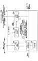
次に、エントロピ復号部1401及びイントラ予測部1406による、復号及びイントラ予測処理の流れについて説明する。図17は、エントロピ復号部及びイントラ予測部による、復号及びイントラ予測処理の流れを示すフローチャートである。<Flow of decoding and intra prediction processing by the entropy decoding unit and the intra prediction unit>
Next, the flow of the decoding and intra prediction processing by the
ステップS1701において、MPM生成部1602は、予測モード保持部1605に保持されている左隣接ブロック及び上隣接ブロックの第1のイントラ予測モードの番号から、MPMリストを生成する。 In step S1701, the
ステップS1702において、算術復号部1502は、符号化ストリームを復号し、IntraLumaMPMFlagを取得する。また、算術復号部1502は、復号したIntraLumaMPMFlagが"1"であった場合、ステップS1703に進む。 In step S1702, the
ステップS1703において、算術復号部1502は、符号化ストリームを復号し、IntraLumaMPMIdxを取得する。 In step S1703, the
ステップS1704において、第1の予測モード算出部1601は、MPMリストにおいて、IntraLumaMPMIdxにより特定される第1のイントラ予測モードの番号を取得する。 In step S1704, the first prediction
一方、ステップS1702において、復号したIntraLumaMPMFlagが"0"であった場合、エントロピ復号部1401は、ステップS1705に進む。 On the other hand, if the decoded IntraLumaMPMFlag is "0" in step S1702, the
ステップS1705において、モード予測値生成部1504は、左隣接ブロック及び上隣接ブロックの第1のイントラ予測モードの番号から、処理対象のブロックのIntraLumaMPMRemainderのMSB予測値を算出する。 In step S1705, the mode prediction value generation unit 1504 calculates the MSB prediction value of the IntraLumaMPMReminder of the block to be processed from the number of the first intra prediction mode of the left adjacent block and the upper adjacent block.
ステップS1706において、算術復号部1502は、符号化ストリームを復号し、IntraLumaMPMRemainderの二値信号を取得する。算術復号部1502では、MSBをコンテキスト適応型二値算術復号し、LSBをバイパスモードの二値算術復号で復号することで、IntraLumaMPMRemainderの二値信号を取得する。 In step S1706, the
ステップS1707において、イントラ予測モード生成部1505は、復号したIntraLumaMPMRemainderの二値信号のMSBと、MSB予測値との排他的論理和を演算する。これにより、イントラ予測モード生成部1505は、処理対象のブロックのIntraLumaMPMRemainderを取得する。 In step S1707, the intra prediction
ステップS1708において、第1の予測モード算出部1601は、IntraLumaMPMRemainderを補正し、第1のイントラ予測モードの番号を取得する。 In step S1708, the first prediction
ステップS1709において、第2の予測モード算出部1604は、処理対象のブロックの横方向画素数及び縦方向画素数を用いて、第1のイントラ予測モードの番号を、第2のイントラ予測モードの番号に変換する。 In step S1709, the second prediction
ステップS1709において、フィルタ部1603は、第2のイントラ予測モードの番号に対応する参照方向を参照し、参照画素のフィルタリング及び予測画素値の生成を行う。 In step S1709, the
以上の説明から明らかなように、第1の実施形態に係る符号化装置では、VVC規格に基づいて6ビット化されたイントラ予測モードの番号の二値信号について、MSB予測値との排他的論理和を演算して、算術符号化する。また、第1の実施形態に係る符号化装置では、当該MSB予測値を、隣接ブロックのイントラ予測モードの番号に基づいて算出する。 As is clear from the above description, in the coding apparatus according to the first embodiment, the binary signal of the intra-prediction mode number converted into 6 bits based on the VVC standard is exclusively ORed with the MSB predicted value. The sum is calculated and arithmetically coded. Further, in the coding apparatus according to the first embodiment, the MSB predicted value is calculated based on the number of the intra prediction mode of the adjacent block.
これにより、第1の実施形態に係る符号化装置によれば、6ビット化されたイントラ予測モードの番号の二値信号を符号化する際、最上位ビットについて、コンテキストモードによる算術符号化を実現する確率を上げることが可能となる。この結果、第1の実施形態に係る符号化装置によれば、6ビット化されたイントラ予測モードの番号の二値信号を符号化した際の符号量を削減することができる。つまり、第1の実施形態に係る符号化装置によれば、イントラ予測において、符号量を削減することができる。 As a result, according to the coding apparatus according to the first embodiment, when encoding the binary signal of the 6-bit intra-prediction mode number, the most significant bit is arithmetically coded in the context mode. It is possible to increase the probability of doing so. As a result, according to the coding apparatus according to the first embodiment, it is possible to reduce the amount of coding when the binary signal of the 6-bit intra-prediction mode number is encoded. That is, according to the coding apparatus according to the first embodiment, the code amount can be reduced in the intra prediction.
また、第1の実施形態に係る復号装置では、符号化ストリームの復号結果に対して、隣接ブロックのイントラ予測モードの番号に基づいて算出したMSB予測値を用いて、イントラ予測モードの番号を算出する。 Further, in the decoding device according to the first embodiment, the intra prediction mode number is calculated using the MSB prediction value calculated based on the intra prediction mode number of the adjacent block for the decoding result of the coded stream. do.
これにより、第1の実施形態に係る復号装置によれば、符号量が削減された符号化ストリームを復号し、イントラ予測モード情報を生成することができる。 Thereby, according to the decoding device according to the first embodiment, it is possible to decode the coded stream with the reduced code amount and generate the intra prediction mode information.
[第2の実施形態]
上記第1の実施形態では、IntraLumaMPMRemainderの二値信号の各ビットのうち、最上位ビット(上位1ビット)について、予測値を算出するものとして説明した。これに対して、第2の実施形態では、上位2ビットについて、予測値を算出する。以下、第2の実施形態について、上記第1の実施形態との相違点を中心に説明する。[Second Embodiment]
In the first embodiment, the predicted value is calculated for the most significant bit (upper 1 bit) of each bit of the binary signal of the IntraLumaMPMReminder. On the other hand, in the second embodiment, the predicted value is calculated for the upper two bits. Hereinafter, the second embodiment will be described focusing on the differences from the first embodiment.
<二値化部の処理の詳細>
はじめに、第2の実施形態における二値化部1101の処理の詳細について説明する。図18は、二値化部により生成された二値信号の具体例を示す第2の図であり、IntraLumaMPMRemainderの二値信号を示す図である。<Details of binarization section processing>
First, the details of the processing of the
上述したとおり、IntraLumaMPMRemainderは、0~63の64通りの番号のいずれかであり、概ね、64通りの参照方向と対応している。したがって、IntraLumaMPMRemainderの二値信号(b0、b1、b2、b3、b4、b5)は、図18のように表すことができる。 As described above, the IntraLumaMPMReminder is one of 64 numbers from 0 to 63, and generally corresponds to 64 reference directions. Therefore, the binary signals (b0, b1, b2, b3, b4, b5) of the IntraLumaMPMReminder can be represented as shown in FIG.
つまり、IntraLumaMPMRemainderの二値信号において、上位2ビット(b0、b1)=(0、0)とは、参照方向が左下隣接ブロック(水平下方向)であることを示しているといえる。 That is, in the binary signal of IntraLumaMPMReminder, the upper 2 bits (b0, b1) = (0,0) can be said to indicate that the reference direction is the lower left adjacent block (horizontal lower direction).
また、IntraLumaMPMRemainderの二値信号において、上位2ビット(b0、b1)=(0、1)とは、参照方向が左上隣接ブロック(水平上方向)であることを示しているといえる。 Further, in the binary signal of IntraLumaMPMReminder, the upper 2 bits (b0, b1) = (0, 1) can be said to indicate that the reference direction is the upper left adjacent block (horizontal upward direction).
また、IntraLumaMPMRemainderの二値信号において、上位2ビット(b0、b1)=(1、0)とは、参照方向が上左隣接ブロック(垂直左方向)であることを示しているといえる。 Further, in the binary signal of IntraLumaMPMReminder, the upper 2 bits (b0, b1) = (1,0) can be said to indicate that the reference direction is the upper left adjacent block (vertical left direction).
更に、IntraLumaMPMRemainderの二値信号において、上位2ビット(b0、b1)=(1、1)とは、参照方向が上右隣接ブロック(垂直右方向)であることを示しているといえる。 Further, in the binary signal of IntraLumaMPMReminder, the upper 2 bits (b0, b1) = (1, 1) can be said to indicate that the reference direction is the upper right adjacent block (vertical right direction).
<モード予測値生成部の処理の詳細>
次に、第2の実施形態におけるモード予測値生成部1104の処理の詳細について説明する。第2の実施形態において、モード予測値生成部1104は、IntraLumaMPMRemainderの二値信号の各ビットの中で、コンテキストを使った二値算術符号化方式を行う上位2ビットの予測値を算出する。具体的には、第2の実施形態において、モード予測値生成部1104は、隣接する第1のイントラ予測モードの番号を以下のように分類する。
・第1のイントラ予測モードの番号が2未満:直流予測またはプレーナ予測
・第1のイントラ予測モードの番号が2~18:水平下方向
・第1のイントラ予測モードの番号が19~34:水平上方向
・第1のイントラ予測モードの番号が35~50:垂直左方向
・第1のイントラ予測モードの番号が51~66:垂直右方向
そして、第2の実施形態において、モード予測値生成部1104は、隣接ブロックの第1のイントラ予測モードの番号に基づいて、上位2ビット(b0、b1)の予測値を算出する。図19は、上位2ビットの予測値の算出方法を説明するための図である。図19の一覧表1900に示すように、第2の実施形態において、モード予測値生成部1104は、上位2ビット(b0、b1)の予測値を以下のように算出する。
・コンテキストモデル1
上隣接ブロックと左隣接ブロックの第1のイントラ予測モードの番号が、いずれも、"直流予測モードまたはプレーナ予測モード"を示す番号であった場合、モード予測値生成部1104では、上位2ビットの予測値を、b0=0、b1=0と算出する。
・コンテキストモデル2
上隣接ブロックと左隣接ブロックの第1のイントラ予測モードの番号のいずれか一方が、"直流予測モードまたはプレーナ予測モード"を示す番号であった場合、
・他方が角度予測モードであり、かつ、参照方向が"水平下方向"を示す番号であった場合、モード予測値生成部1104では、b0=0、b1=0と算出する。<Details of processing in the mode prediction value generator>
Next, the details of the processing of the mode prediction
・ The number of the first intra prediction mode is less than 2: DC prediction or planar prediction ・ The number of the first intra prediction mode is 2 to 18: horizontal downward ・ The number of the first intra prediction mode is 19 to 34: horizontal Upward ・ The number of the first intra prediction mode is 35 to 50: vertical left direction ・ The number of the first intra prediction mode is 51 to 66: vertical right direction And, in the second embodiment, the mode prediction value generation unit. The 1104 calculates the predicted value of the upper two bits (b0, b1) based on the number of the first intra prediction mode of the adjacent block. FIG. 19 is a diagram for explaining a method of calculating the predicted value of the upper two bits. As shown in the
・
When the numbers of the first intra prediction modes of the upper adjacent block and the left adjacent block are both numbers indicating "DC prediction mode or planar prediction mode", the mode prediction
・
If either the number of the first intra prediction mode of the upper adjacent block or the left adjacent block is a number indicating "DC prediction mode or planar prediction mode",
-When the other is the angle prediction mode and the reference direction is a number indicating "horizontal downward direction", the mode prediction
・他方が角度予測モードであり、かつ、参照方向が"水平上方向"を示す番号であった場合、モード予測値生成部1104では、b0=0、b1=1と算出する。 -When the other is the angle prediction mode and the reference direction is a number indicating "horizontal upward direction", the mode prediction
・他方が角度予測モードであり、かつ、参照方向が"垂直左方向"を示す番号であった場合、モード予測値生成部1104では、b0=1、b1=0と算出する。 -When the other is the angle prediction mode and the reference direction is a number indicating "vertical left direction", the mode prediction
・他方が角度予測モードであり、かつ、参照方向が"垂直右方向"を示す番号であった場合、モード予測値生成部1104では、b0=1、b1=1と算出する。
・コンテキストモデル3
上隣接ブロックと左隣接ブロックの第1のイントラ予測モードの番号が、いずれも、"直流予測モードまたはプレーナ予測モード"を示す番号ではなく、かつ、両方が角度予測モードであり、かつ、"水平下方向"または"水平上方向"を示す番号であって、
・両方とも"水平上方向"を示す番号であった場合、モード予測値生成部1104では、b0=0、b1=1と算出する。-When the other is the angle prediction mode and the reference direction is a number indicating "vertical right direction", the mode prediction
・
The numbers of the first intra prediction modes of the upper adjacent block and the left adjacent block are neither numbers indicating "DC prediction mode or planar prediction mode", and both are angle prediction modes and "horizontal". A number indicating "downward" or "horizontal upward"
-If both are numbers indicating "horizontal upward direction", the mode prediction
・両方とも"水平上方向"を示す番号以外の番号であった場合、モード予測値生成部1104では、b0=0、b1=0と算出する。 -If both are numbers other than the numbers indicating "horizontal upward direction", the mode prediction
また、上隣接ブロックと左隣接ブロックの第1のイントラ予測モードの番号が、いずれも、"直流予測モードまたはプレーナ予測モード"を示す番号ではなく、かつ、両方が角度予測モードであり、かつ、"垂直左方向"または"垂直右方向"を示す番号であって、
・両方とも"垂直右方向"を示す番号であった場合、モード予測値生成部1104では、b0=1、b1=1と算出する。Further, the numbers of the first intra prediction modes of the upper adjacent block and the left adjacent block are neither numbers indicating "DC prediction mode or planar prediction mode", and both are in the angle prediction mode, and A number indicating "vertical left" or "vertical right"
-If both are numbers indicating "vertical right direction", the mode prediction
・両方とも"垂直右方向"を示す番号以外の番号であった場合、モード予測値生成部1104では、b0=1、b1=0と算出する。
・コンテキストモデル4
上隣接ブロックと左隣接ブロックの第1のイントラ予測モードの番号のいずれか一方が、角度予測モードであって、"水平下方向"または"水平上方向"を示す番号の場合、
・他方が"垂直左方向"または"垂直右方向"を示す番号であった場合、モード予測値生成部1104では、b0=0、b1=0と算出する。-If both are numbers other than the numbers indicating "vertical right direction", the mode prediction
・
If either the number of the first intra prediction mode of the upper adjacent block or the left adjacent block is the angle prediction mode and the number indicates "horizontal downward" or "horizontal upward",
When the other is a number indicating "vertical left direction" or "vertical right direction", the mode prediction
<イントラ予測モード生成部による処理>
次に、第2の実施形態における、イントラ予測モード生成部1505による処理の詳細について説明する。第2の実施形態において、イントラ予測モード生成部1505では、IntraLumaMPMRemainderの二値信号(b0、b1、b2、b3、b4、b5)を、下式に基づいて多値化する。<Processing by the intra prediction mode generator>
Next, the details of the processing by the intra prediction

以上の説明から明らかなように、第2の実施形態に係る符号化装置では、VVC規格に基づいて6ビット化されたイントラ予測モードの番号の二値信号について、上位2ビットの予測値との排他的論理和を演算して、算術符号化する。また、第2の実施形態に係る符号化装置では、当該上位2ビットの予測値を、隣接ブロックのイントラ予測モードの番号に基づいて算出する。 As is clear from the above description, in the coding apparatus according to the second embodiment, the binary signal of the intra prediction mode number converted into 6 bits based on the VVC standard is different from the predicted value of the upper 2 bits. Arithmetically encode the exclusive OR. Further, in the coding apparatus according to the second embodiment, the predicted value of the upper two bits is calculated based on the number of the intra prediction mode of the adjacent block.
これにより、第2の実施形態に係る符号化装置によれば、6ビット化されたイントラ予測モードの番号の二値信号を符号化する際、上位2ビットについて、コンテキストモードによる算術符号化を実現する確率を上げることが可能となる。この結果、第2の実施形態に係る符号化装置によれば、6ビット化されたイントラ予測モードの番号の二値信号を符号化した際の符号量を削減することができる。つまり、第2の実施形態に係る符号化装置によれば、イントラ予測において、符号量を削減することができる。 As a result, according to the coding apparatus according to the second embodiment, when encoding the binary signal of the 6-bit intra-prediction mode number, the upper two bits are arithmetically coded in the context mode. It is possible to increase the probability of doing so. As a result, according to the coding apparatus according to the second embodiment, it is possible to reduce the amount of coding when the binary signal of the 6-bit intra-prediction mode number is encoded. That is, according to the coding apparatus according to the second embodiment, the code amount can be reduced in the intra prediction.
また、第2の実施形態に係る復号装置では、符号化ストリームの復号結果に対して、隣接ブロックのイントラ予測モードの番号に基づいて算出した上位2ビットの予測値を用いて、イントラ予測モードの番号を算出する。 Further, in the decoding device according to the second embodiment, the predicted value of the upper two bits calculated based on the number of the intra prediction mode of the adjacent block is used for the decoding result of the coded stream in the intra prediction mode. Calculate the number.
これにより、第1の実施形態に係る復号装置によれば、符号量が削減された符号化ストリームを復号し、イントラ予測モード情報を生成することができる。 Thereby, according to the decoding device according to the first embodiment, it is possible to decode the coded stream with the reduced code amount and generate the intra prediction mode information.
[その他の実施形態]
上記第1及び第2の実施形態では、IntraLumaMPMRemainderの二値信号の、上位1ビットまたは上位2ビットについて、予測値を算出するものとして説明した。しかしながら、予測値の算出対象ビットはこれに限定されるものではなく、上位mビット(mは1以上の整数)について、予測値を算出するように構成してもよい。この場合、算術符号化部1102では、IntraLumaMPMRemainderの上位mビットについては、コンテキストモードによる算術符号化を行い、上位mビット以外の各ビットの値について、バイパスモードによる算術符号化を行うことになる。[Other embodiments]
In the first and second embodiments described above, the predicted value is calculated for the upper 1 bit or the upper 2 bits of the binary signal of the IntraLumaMPMReminder. However, the calculation target bit of the predicted value is not limited to this, and the predicted value may be calculated for the upper m bits (m is an integer of 1 or more). In this case, the
また、上記第1及び第2の実施形態では、符号化装置と復号装置とを別体の装置として説明したが、符号化装置と復号装置とは一体の装置であってもよい。 Further, in the first and second embodiments, the coding device and the decoding device have been described as separate devices, but the coding device and the decoding device may be integrated devices.
なお、上記実施形態に挙げた構成等に、その他の要素との組み合わせ等、ここで示した構成に本発明が限定されるものではない。これらの点に関しては、本発明の趣旨を逸脱しない範囲で変更することが可能であり、その応用形態に応じて適切に定めることができる。 The present invention is not limited to the configurations shown here, such as combinations with other elements in the configurations and the like described in the above embodiments. These points can be changed without departing from the spirit of the present invention, and can be appropriately determined according to the application form thereof.
110 :符号化装置
120 :復号装置
208 :イントラ予測部
211 :エントロピ符号化部
901 :制御部
902 :第2の予測モード算出部
903 :フィルタ部
904 :コスト算出部
905 :予測モード保持部
906 :MPM生成部
1101 :二値化部
1102 :算術符号化部
1103 :コンテキスト保持・計算部
1104 :モード予測値生成部
1105 :符号化値生成部
1401 :エントロピ復号部
1406 :イントラ予測部
1501 :コンテキスト保持・計算部
1502 :算術復号部
1503 :二値化部
1504 :モード予測値生成部
1505 :イントラ予測モード生成部
1601 :第1の予測モード算出部
1602 :MPM生成部
1603 :フィルタ部
1604 :第2の予測モード算出部
1605 :予測モード保持部110: Coding device 120: Decoding device 208: Intra prediction unit 211: Entropy coding unit 901: Control unit 902: Second prediction mode calculation unit 903: Filter unit 904: Cost calculation unit 905: Prediction mode holding unit 906: MPM generation unit 1101: Binarization unit 1102: Arithmetic coding unit 1103: Context retention / calculation unit 1104: Mode prediction value generation unit 1105: Coded value generation unit 1401: Entropy decoding unit 1406: Intra prediction unit 1501: Context retention -Calculation unit 1502: Arithmetic decoding unit 1503: Binarization unit 1504: Mode prediction value generation unit 1505: Intra-prediction mode generation unit 1601: First prediction mode calculation unit 1602: MPM generation unit 1603: Filter unit 1604: Second Prediction mode calculation unit 1605: Prediction mode holding unit
Claims (13)
Translated fromJapanese前記処理対象のブロックに隣接する隣接ブロックでのイントラ予測において生成された、前記参照方向に応じた値から、前記処理対象のブロックでの予測値を算出する算出部と、
前記処理対象のブロックでのイントラ予測において生成された、前記参照方向に応じた値と前記予測値とに基づいて、算術符号化のための二値信号を生成する生成部と、を有し、
前記生成部は、
前記参照方向に応じた値に基づいて生成された二値信号の上位mビット(mは1以上の整数)の値について、前記予測値との排他的論理和を演算することで、前記算術符号化のための二値信号を生成することを特徴とする符号化装置。A conversion unit that generates a value according to the reference direction by converting a value indicating the reference direction selected in the intra prediction in the block to be processed according to the shape of the block to be processed.
A calculation unit that calculates the predicted value in the block to be processed from the value corresponding to the reference direction generated in the intra prediction in the adjacent block adjacent to the block to be processed.
It has a generator that generates a binary signal for arithmetic coding based on the value corresponding to the reference direction and the predicted value generated in the intra prediction in the block to be processed.
The generator is
The arithmetic code is obtained by calculating the exclusive OR with the predicted value for the value of the upper m bits (m is an integer of 1 or more) of the binary signal generated based on the value corresponding to the reference direction. An encoding device characterizedby generating a binary signal for conversion.
前記処理対象のブロックの上側に隣接する上隣接ブロック及び左側に隣接する左隣接ブロックでのイントラ予測において生成された、前記参照方向に応じた値から、前記処理対象のブロックでの前記予測値を算出することを特徴とする請求項1に記載の符号化装置。The calculation unit
From the values corresponding to the reference direction generated in the intra prediction in the upper adjacent block adjacent to the upper side of the block to be processed and the left adjacent block adjacent to the left side, the predicted value in the block to be processed is obtained. The coding apparatus according to claim 1, wherein the encoding device is calculated.
前記算術符号化のための二値信号のうち、上位mビット以外の各ビットの値について、バイパスモードにより算術符号化することを特徴とする請求項3に記載の符号化装置。The coding unit is
The coding device according to claim3 , wherein the value of each bit other than the upper m bits of the binary signal for arithmetic coding is arithmetically coded in a bypass mode.
前記処理対象のブロックに隣接する隣接ブロックでのイントラ予測において生成された、前記参照方向に応じた値から、前記処理対象のブロックでの予測値を算出する算出部と、
前記処理対象のブロックでのイントラ予測において生成された、前記参照方向に応じた値と前記予測値とに基づいて、算術符号化のための二値信号を生成する生成部と、を有し、
前記算出部は、
前記処理対象のブロックに隣接する隣接ブロックでのイントラ予測において生成された、前記参照方向に応じた値が、水平方向を示す値であるか、垂直方向を示す値であるかを判定することで、前記予測値を算出することを特徴とする符号化装置。A conversion unit that generates a value according to the reference direction by converting a value indicating the reference direction selected in the intra prediction in the block to be processed according to the shape of the block to be processed.
A calculation unit that calculates the predicted value in the block to be processed from the value corresponding to the reference direction generated in the intra prediction in the adjacent block adjacent to the block to be processed .
It has a generator that generates a binary signal for arithmetic coding based on the value corresponding to the reference direction and the predicted value generated in the intra prediction in the block to be processed.
The calculation unit
By determining whether the value corresponding to the reference direction generated in the intra prediction in the adjacent block adjacent to the block to be processed is a value indicating the horizontal direction or a value indicating the vertical direction. ,A coding device characterized by calculating the predicted value.
前記処理対象のブロックに隣接する隣接ブロックでのイントラ予測において生成された、前記参照方向に応じた値から、前記処理対象のブロックでの予測値を算出し、
前記処理対象のブロックでのイントラ予測において生成された、前記参照方向に応じた値と前記予測値とに基づいて、算術符号化のための二値信号を生成する処理をコンピュータが実行する符号化方法であって、
前記生成する処理は、
前記参照方向に応じた値に基づいて生成された二値信号の上位mビット(mは1以上の整数)の値について、前記予測値との排他的論理和を演算することで、前記算術符号化のための二値信号を生成する符号化方法。By converting the value indicating the reference direction selected in the intra prediction in the block to be processed according to the shape of the block to be processed, a value corresponding to the reference direction is generated.
The predicted value in the block to be processed is calculated from the value corresponding to the reference direction generated in the intra prediction in the adjacent block adjacent to the block to be processed.
Coding in which a computer executes aprocess of generating a binary signal for arithmetic coding based on the value corresponding to the reference direction and the predicted value generated in the intra prediction in the block to be processed. It ’sa method,
The process to be generated is
The arithmetic code is obtained by calculating the exclusive OR with the predicted value for the value of the upper m bits (m is an integer of 1 or more) of the binary signal generated based on the value corresponding to the reference direction. A coding method that produces a binary signal for conversion .
前記処理対象のブロックに隣接する隣接ブロックでのイントラ予測において生成された、前記参照方向に応じた値から、前記処理対象のブロックでの予測値を算出し、
前記処理対象のブロックでのイントラ予測において生成された、前記参照方向に応じた値と前記予測値とに基づいて、算術符号化のための二値信号を生成する処理をコンピュータに実行させるための符号化プログラムであって、
前記生成する処理は、
前記参照方向に応じた値に基づいて生成された二値信号の上位mビット(mは1以上の整数)の値について、前記予測値との排他的論理和を演算することで、前記算術符号化のための二値信号を生成する符号化プログラム。By converting the value indicating the reference direction selected in the intra prediction in the block to be processed according to the shape of the block to be processed, a value corresponding to the reference direction is generated.
The predicted value in the block to be processed is calculated from the value corresponding to the reference direction generated in the intra prediction in the adjacent block adjacent to the block to be processed.
To make a computer execute aprocess of generating a binary signal for arithmetic coding based on the value corresponding to the reference direction and the predicted value generated in the intra prediction in the block to be processed.It's an arithmetic program
The process to be generated is
The arithmetic code is obtained by calculating the exclusive OR with the predicted value for the value of the upper m bits (m is an integer of 1 or more) of the binary signal generated based on the value corresponding to the reference direction. An encoding program that produces a binary signal for conversion .
前記処理対象のブロックの形状に応じて変換することで、前記イントラ予測モード情報から参照方向を示す値を算出し、前記処理対象のブロックでのイントラ予測を行う予測部と、を有し、
前記復号部は、
前記予測部が前記処理対象のブロックに隣接する隣接ブロックでのイントラ予測を行う際に用いた、前記イントラ予測モード情報に基づいて、前記処理対象のブロックでの予測値を算出する算出部と、
前記符号化ストリームを復号した二値信号の上位mビットの値について、前記予測値との排他的論理和を演算することで、前記イントラ予測モード情報を生成する生成部と
を有することを特徴とする復号装置。A decoding unit that decodes the coded stream and generates intra-prediction mode information for the block to be processed.
It has a prediction unit that calculates a value indicating a reference direction from the intra prediction mode information by converting according to the shape of the block to be processed, and performs intra prediction in the block to be processed.
The decoding unit
A calculation unit that calculates a prediction value in the block to be processed based on the intra prediction mode information used by the prediction unit when performing an intra prediction in an adjacent block adjacent to the block to be processed.
With the generator that generates the intra prediction mode information by calculating the exclusive OR with the predicted value for the value of the upper m bits of the binary signal obtained by decoding the coded stream.
A decoding device characterized by having .
前記処理対象のブロックの上側に隣接する上隣接ブロック及び左側に隣接する左隣接ブロックでのイントラ予測を行う際に用いた、前記イントラ予測モード情報に基づいて、前記処理対象のブロックでの前記予測値を算出することを特徴とする請求項9に記載の復号装置。The calculation unit
The prediction in the block to be processed is based on the intra prediction mode information used when performing the intra prediction in the upper adjacent block adjacent to the upper side of the block to be processed and the left adjacent block adjacent to the left side. The decoding device according to claim9 , wherein the value is calculated.
前記処理対象のブロックの形状に応じて変換することで、前記イントラ予測モード情報から参照方向を示す値を算出し、前記処理対象のブロックでのイントラ予測を行う予測部と、を有し、
前記復号部は、
前記予測部が前記処理対象のブロックに隣接する隣接ブロックでのイントラ予測を行う際に用いた、前記イントラ予測モード情報に基づいて、前記処理対象のブロックでの予測値を算出する算出部と、
前記予測値を用いて前記イントラ予測モード情報を生成する生成部と、を有し、
前記算出部は、
前記予測部が前記処理対象のブロックに隣接する隣接ブロックでのイントラ予測を行う際に用いた、前記イントラ予測モード情報から算出される参照方向に応じた値が、水平方向を示す値であるか、垂直方向を示す値であるかを判定することで、前記予測値を算出することを特徴とする復号装置。A decoding unit that decodes the coded stream and generates intra-prediction mode information for the block to be processed.
It has a prediction unit that calculates a value indicating a reference direction from the intra prediction mode information by converting according to the shape of the block to be processed, and performs intra prediction in the block to be processed.
The decoding unit
A calculation unit that calculates a prediction value in the block to be processed based on the intra prediction mode information used by the prediction unit when performing an intra prediction in an adjacent block adjacent to the block to be processed.
It has a generation unit that generates the intra prediction mode information using the predicted value, and has.
The calculation unit
Whether the value corresponding to the reference direction calculated from the intra prediction mode information used by the prediction unit when performing the intra prediction in the adjacent block adjacent to the block to be processed is a value indicating the horizontal direction. ,A decoding device, characterized in that the predicted value is calculated by determining whether the value indicates a vertical direction.
前記処理対象のブロックの形状に応じて変換することで、前記イントラ予測モード情報から参照方向を示す値を算出し、前記処理対象のブロックでのイントラ予測を行う、処理をコンピュータが実行する復号方法であって、
前記生成する処理は、
前記イントラ予測を行う処理が、前記処理対象のブロックに隣接する隣接ブロックでのイントラ予測を行う際に用いた、前記イントラ予測モード情報に基づいて、前記処理対象のブロックでの予測値を算出し、
前記符号化ストリームを復号した二値信号の上位mビットの値について、前記予測値との排他的論理和を演算することで、前記イントラ予測モード情報を生成する、
ことを特徴とする復号方法。Decodes the coded stream, generates intra-prediction mode information for the block to be processed,
A decoding method in which a computer executes processing by calculating a value indicating a reference direction from the intra prediction mode information by converting according to the shape of the block to be processed and performing intra prediction in the block to be processed. And
The process to be generated is
Based on the intra-prediction mode information used when the process of performing the intra-prediction performs the intra-prediction in the adjacent block adjacent to the block to be processed, the predicted value in the block to be processed is calculated. ,
The intra prediction mode information is generated by calculating the exclusive OR with the predicted value for the value of the upper m bits of the binary signal obtained by decoding the coded stream.
A decryption method characterized by that.
前記処理対象のブロックの形状に応じて変換することで、前記イントラ予測モード情報から参照方向を示す値を算出し、前記処理対象のブロックでのイントラ予測を行う、処理をコンピュータに実行させるための復号プログラムであって、
前記生成する処理は、
前記イントラ予測を行う処理が、前記処理対象のブロックに隣接する隣接ブロックでのイントラ予測を行う際に用いた、前記イントラ予測モード情報に基づいて、前記処理対象のブロックでの予測値を算出し、
前記符号化ストリームを復号した二値信号の上位mビットの値について、前記予測値との排他的論理和を演算することで、前記イントラ予測モード情報を生成する
ことを特徴とする復号プログラム。Decodes the coded stream, generates intra-prediction mode information for the block to be processed,
By converting according to the shape of the block to be processed, a value indicating a reference direction is calculated from the intra prediction mode information, and intra prediction is performed in the block to be processed. It ’s a decryption program.
The process to be generated is
Based on the intra-prediction mode information used when the process of performing the intra-prediction performs the intra-prediction in the adjacent block adjacent to the block to be processed, the predicted value in the block to be processed is calculated. ,
The intra prediction mode information is generated by calculating the exclusive OR with the predicted value for the value of the upper m bits of the binary signal obtained by decoding the coded stream.
A decryption program characterized by that.
Applications Claiming Priority (1)
| Application Number | Priority Date | Filing Date | Title |
|---|---|---|---|
| PCT/JP2018/034886WO2020059092A1 (en) | 2018-09-20 | 2018-09-20 | Encoding device, encoding method, encoding program, decoding device, decoding method and decoding program |
Publications (2)
| Publication Number | Publication Date |
|---|---|
| JPWO2020059092A1 JPWO2020059092A1 (en) | 2021-06-10 |
| JP7040629B2true JP7040629B2 (en) | 2022-03-23 |
Family
ID=69888607
Family Applications (1)
| Application Number | Title | Priority Date | Filing Date |
|---|---|---|---|
| JP2020547555AActiveJP7040629B2 (en) | 2018-09-20 | 2018-09-20 | Encoding device, coding method, coding program, decoding device, decoding method and decoding program |
Country Status (3)
| Country | Link |
|---|---|
| US (1) | US11381810B2 (en) |
| JP (1) | JP7040629B2 (en) |
| WO (1) | WO2020059092A1 (en) |
Citations (2)
| Publication number | Priority date | Publication date | Assignee | Title |
|---|---|---|---|---|
| WO2018070107A1 (en) | 2016-10-14 | 2018-04-19 | シャープ株式会社 | Entropy decoding apparatus, entropy encoding device, image decoding apparatus and image encoding apparatus |
| WO2018117894A1 (en) | 2016-12-23 | 2018-06-28 | Huawei Technologies Co., Ltd | An encoding apparatus for signaling an extension directional intra-prediction mode within a set of directional intra-prediction modes |
Family Cites Families (9)
| Publication number | Priority date | Publication date | Assignee | Title |
|---|---|---|---|---|
| JP4722214B2 (en)* | 2007-04-18 | 2011-07-13 | 三菱電機株式会社 | Encoding device, decoding device, code conversion device, and program |
| CN102595121A (en)* | 2011-01-15 | 2012-07-18 | 华为技术有限公司 | Intra-frame prediction mode binarization method, device and system as well as decoding method |
| EP3306933A4 (en)* | 2015-05-27 | 2019-05-08 | KT Corporation | METHOD AND DEVICE FOR PROCESSING VIDEO SIGNAL |
| US10419772B2 (en)* | 2015-10-28 | 2019-09-17 | Qualcomm Incorporated | Parallel arithmetic coding techniques |
| US10440399B2 (en)* | 2015-11-13 | 2019-10-08 | Qualcomm Incorporated | Coding sign information of video data |
| US10506228B2 (en)* | 2016-10-04 | 2019-12-10 | Qualcomm Incorporated | Variable number of intra modes for video coding |
| CN111819852B (en)* | 2018-03-07 | 2023-06-02 | 华为技术有限公司 | Method and device for residual sign prediction in transform domain |
| CN111819854B (en)* | 2018-03-07 | 2022-12-06 | 华为技术有限公司 | Method and apparatus for coordinating multi-sign bit concealment and residual symbol prediction |
| EP3738309B1 (en)* | 2018-03-07 | 2025-01-01 | Huawei Technologies Co., Ltd. | Method and apparatus for detecting blocks suitable for multiple sign bit hiding |
- 2018
- 2018-09-20JPJP2020547555Apatent/JP7040629B2/enactiveActive
- 2018-09-20WOPCT/JP2018/034886patent/WO2020059092A1/ennot_activeCeased
- 2021
- 2021-02-12USUS17/174,374patent/US11381810B2/enactiveActive
Patent Citations (2)
| Publication number | Priority date | Publication date | Assignee | Title |
|---|---|---|---|---|
| WO2018070107A1 (en) | 2016-10-14 | 2018-04-19 | シャープ株式会社 | Entropy decoding apparatus, entropy encoding device, image decoding apparatus and image encoding apparatus |
| WO2018117894A1 (en) | 2016-12-23 | 2018-06-28 | Huawei Technologies Co., Ltd | An encoding apparatus for signaling an extension directional intra-prediction mode within a set of directional intra-prediction modes |
Non-Patent Citations (3)
| Title |
|---|
| Benjamin Bross, Jianle Chen, and Shan Liu,Versatile Video Coding (Draft 2),Joint Video Experts Team (JVET) of ITU-T SG 16 WP 3 and ISO/IEC JTC 1/SC 29/WG 11,JVET-K1001-v4,11th Meeting: Ljubljana, SI,2018年08月17日,pp.27-28,43-55,73-76 |
| Fabien Racape, et al.,CE3-related: Wide-angle intra prediction for non-square blocks,Joint Video Experts Team (JVET) of ITU-T SG 16 WP 3 and ISO/IEC JTC 1/SC 29/WG 11,JVET-K0500_r4,11th Meeting: Ljubljana, SI,2018年07月,pp.1-13 |
| Liang Zhao, Shan Liu, Xin Zhao, and Xiang Li,CE3-related: Wide angular intra prediction for non-square blocks,Joint Video Exploration Team (JVET) of ITU-T SG 16 WP 3 and ISO/IEC JTC 1/SC 29/WG 11,JVET-K0289_v2,11th Meeting: Ljubljana, SI,2018年07月,pp.1-4 |
Also Published As
| Publication number | Publication date |
|---|---|
| JPWO2020059092A1 (en) | 2021-06-10 |
| US20210168358A1 (en) | 2021-06-03 |
| WO2020059092A1 (en) | 2020-03-26 |
| US11381810B2 (en) | 2022-07-05 |
Similar Documents
| Publication | Publication Date | Title |
|---|---|---|
| US12149736B2 (en) | Method, apparatus, and system for encoding and decoding image using LM chroma prediction | |
| US9729872B2 (en) | Method and apparatus for encoding/decoding images to minimize redundancy of intra-prediction mode | |
| KR101772459B1 (en) | New intra prediction modes | |
| JP5686499B2 (en) | Image predictive encoding apparatus, method and program, image predictive decoding apparatus, method and program, and encoding / decoding system and method | |
| US20090110070A1 (en) | Image encoding device and encoding method, and image decoding device and decoding method | |
| WO2020253828A1 (en) | Coding and decoding method and device, and storage medium | |
| KR101314836B1 (en) | Predicted pixel value generation procedure automatic producing method, image encoding method, image decoding method, apparatus therefor, programs therefor, and storage media which store the programs | |
| JP5469193B2 (en) | Target block processing method, system thereof, and computer-readable medium | |
| JP2015111954A (en) | Method and apparatus for encoding and decoding video by using large-sized transform unit | |
| CN104054350A (en) | Method and apparatus for video encoding | |
| TWI727826B (en) | Coding using intra-prediction | |
| US20210266527A1 (en) | Video signal processing method and device using reference sample | |
| KR20080110171A (en) | Method and apparatus for intra prediction coding and decoding using image reconstruction | |
| US20200221140A1 (en) | Method and apparatus for determining coding tree node split mode and coding device | |
| US9848204B2 (en) | Spatial prediction method and device, coding and decoding methods and devices | |
| JP2019531031A (en) | Method and apparatus for encoding video | |
| JP2024511272A (en) | Intra prediction method, encoder, decoder and storage medium | |
| JP2002290243A (en) | Encoding method, encoding device, decoding method, and decoding device | |
| JP7040629B2 (en) | Encoding device, coding method, coding program, decoding device, decoding method and decoding program | |
| US8463057B2 (en) | Image encoding apparatus and control method therefor | |
| JP6992825B2 (en) | Video coding device, video coding method, video decoding device, video decoding method, and video coding system | |
| CN110446048B (en) | Method and device for selecting prediction mode in intra-frame prediction scene | |
| TWI856179B (en) | Image encoding device and control method thereof, and image decoding device and control method thereof | |
| KR102235314B1 (en) | Video encoding/decoding method and apparatus using paddding in video codec | |
| WO2022191947A1 (en) | State based dependent quantization and residual coding in video coding |
Legal Events
| Date | Code | Title | Description |
|---|---|---|---|
| A621 | Written request for application examination | Free format text:JAPANESE INTERMEDIATE CODE: A621 Effective date:20201126 | |
| A131 | Notification of reasons for refusal | Free format text:JAPANESE INTERMEDIATE CODE: A131 Effective date:20211207 | |
| A521 | Request for written amendment filed | Free format text:JAPANESE INTERMEDIATE CODE: A523 Effective date:20220121 | |
| TRDD | Decision of grant or rejection written | ||
| A01 | Written decision to grant a patent or to grant a registration (utility model) | Free format text:JAPANESE INTERMEDIATE CODE: A01 Effective date:20220208 | |
| A61 | First payment of annual fees (during grant procedure) | Free format text:JAPANESE INTERMEDIATE CODE: A61 Effective date:20220221 | |
| R150 | Certificate of patent or registration of utility model | Ref document number:7040629 Country of ref document:JP Free format text:JAPANESE INTERMEDIATE CODE: R150 |