JP7040458B2 - Sound output device, function execution method and program of sound output device - Google Patents
Sound output device, function execution method and program of sound output deviceDownload PDFInfo
- Publication number
- JP7040458B2 JP7040458B2JP2018547196AJP2018547196AJP7040458B2JP 7040458 B2JP7040458 B2JP 7040458B2JP 2018547196 AJP2018547196 AJP 2018547196AJP 2018547196 AJP2018547196 AJP 2018547196AJP 7040458 B2JP7040458 B2JP 7040458B2
- Authority
- JP
- Japan
- Prior art keywords
- fingerprint
- output device
- fingerprint information
- acoustic output
- database
- Prior art date
- Legal status (The legal status is an assumption and is not a legal conclusion. Google has not performed a legal analysis and makes no representation as to the accuracy of the status listed.)
- Active
Links
Images


Classifications
- G—PHYSICS
- G06—COMPUTING OR CALCULATING; COUNTING
- G06V—IMAGE OR VIDEO RECOGNITION OR UNDERSTANDING
- G06V40/00—Recognition of biometric, human-related or animal-related patterns in image or video data
- G06V40/10—Human or animal bodies, e.g. vehicle occupants or pedestrians; Body parts, e.g. hands
- G06V40/12—Fingerprints or palmprints
- G06V40/1365—Matching; Classification
- G—PHYSICS
- G06—COMPUTING OR CALCULATING; COUNTING
- G06T—IMAGE DATA PROCESSING OR GENERATION, IN GENERAL
- G06T7/00—Image analysis
- G06T7/0002—Inspection of images, e.g. flaw detection
- G06T7/0012—Biomedical image inspection
- G06T7/0014—Biomedical image inspection using an image reference approach
- G—PHYSICS
- G06—COMPUTING OR CALCULATING; COUNTING
- G06V—IMAGE OR VIDEO RECOGNITION OR UNDERSTANDING
- G06V40/00—Recognition of biometric, human-related or animal-related patterns in image or video data
- G06V40/10—Human or animal bodies, e.g. vehicle occupants or pedestrians; Body parts, e.g. hands
- G06V40/12—Fingerprints or palmprints
- H—ELECTRICITY
- H04—ELECTRIC COMMUNICATION TECHNIQUE
- H04R—LOUDSPEAKERS, MICROPHONES, GRAMOPHONE PICK-UPS OR LIKE ACOUSTIC ELECTROMECHANICAL TRANSDUCERS; DEAF-AID SETS; PUBLIC ADDRESS SYSTEMS
- H04R1/00—Details of transducers, loudspeakers or microphones
- H04R1/10—Earpieces; Attachments therefor ; Earphones; Monophonic headphones
- H04R1/1041—Mechanical or electronic switches, or control elements
- G—PHYSICS
- G06—COMPUTING OR CALCULATING; COUNTING
- G06V—IMAGE OR VIDEO RECOGNITION OR UNDERSTANDING
- G06V40/00—Recognition of biometric, human-related or animal-related patterns in image or video data
- G06V40/10—Human or animal bodies, e.g. vehicle occupants or pedestrians; Body parts, e.g. hands
- G06V40/12—Fingerprints or palmprints
- G06V40/13—Sensors therefor
- G06V40/1306—Sensors therefor non-optical, e.g. ultrasonic or capacitive sensing
- G—PHYSICS
- G06—COMPUTING OR CALCULATING; COUNTING
- G06V—IMAGE OR VIDEO RECOGNITION OR UNDERSTANDING
- G06V40/00—Recognition of biometric, human-related or animal-related patterns in image or video data
- G06V40/10—Human or animal bodies, e.g. vehicle occupants or pedestrians; Body parts, e.g. hands
- G06V40/12—Fingerprints or palmprints
- G06V40/13—Sensors therefor
- G06V40/1318—Sensors therefor using electro-optical elements or layers, e.g. electroluminescent sensing
- H—ELECTRICITY
- H04—ELECTRIC COMMUNICATION TECHNIQUE
- H04R—LOUDSPEAKERS, MICROPHONES, GRAMOPHONE PICK-UPS OR LIKE ACOUSTIC ELECTROMECHANICAL TRANSDUCERS; DEAF-AID SETS; PUBLIC ADDRESS SYSTEMS
- H04R1/00—Details of transducers, loudspeakers or microphones
- H04R1/10—Earpieces; Attachments therefor ; Earphones; Monophonic headphones
- H04R1/1016—Earpieces of the intra-aural type
- H—ELECTRICITY
- H04—ELECTRIC COMMUNICATION TECHNIQUE
- H04R—LOUDSPEAKERS, MICROPHONES, GRAMOPHONE PICK-UPS OR LIKE ACOUSTIC ELECTROMECHANICAL TRANSDUCERS; DEAF-AID SETS; PUBLIC ADDRESS SYSTEMS
- H04R2420/00—Details of connection covered by H04R, not provided for in its groups
- H04R2420/07—Applications of wireless loudspeakers or wireless microphones
- H—ELECTRICITY
- H04—ELECTRIC COMMUNICATION TECHNIQUE
- H04R—LOUDSPEAKERS, MICROPHONES, GRAMOPHONE PICK-UPS OR LIKE ACOUSTIC ELECTROMECHANICAL TRANSDUCERS; DEAF-AID SETS; PUBLIC ADDRESS SYSTEMS
- H04R5/00—Stereophonic arrangements
- H04R5/033—Headphones for stereophonic communication
Landscapes
- Engineering & Computer Science (AREA)
- Physics & Mathematics (AREA)
- Theoretical Computer Science (AREA)
- General Physics & Mathematics (AREA)
- Multimedia (AREA)
- Human Computer Interaction (AREA)
- Acoustics & Sound (AREA)
- Signal Processing (AREA)
- Computer Vision & Pattern Recognition (AREA)
- Quality & Reliability (AREA)
- Radiology & Medical Imaging (AREA)
- Nuclear Medicine, Radiotherapy & Molecular Imaging (AREA)
- Medical Informatics (AREA)
- General Health & Medical Sciences (AREA)
- Health & Medical Sciences (AREA)
- Image Input (AREA)
- Collating Specific Patterns (AREA)
- Headphones And Earphones (AREA)
- Measurement Of The Respiration, Hearing Ability, Form, And Blood Characteristics Of Living Organisms (AREA)
- Telephone Function (AREA)
Description
Translated fromJapanese本開示は、音響出力装置、音響出力装置の機能実行方法及びプログラムに関する。 The present disclosure relates to an acoustic output device, a function execution method and a program of the acoustic output device.
従来、例えば下記の特許文献1には、装置本体に指紋検出照合機能を有するICカードを装着することができるようにすることで、周辺機器の接続部が少ない情報処理装置にも簡単に指紋検出照合機能を加えることができる入力装置に関して記載されている。 Conventionally, for example, in
近年、ユーザの身体に装着するスマートウォッチなどのウェアラブル機器が普及している。ウェアラブル機器は、その手軽さ、携帯性、小型化などを追及していくことを考えると、ボタンなどの操作部はますます小さくなることが想定され、操作部が小さくなることによる操作性の低下が懸念される。 In recent years, wearable devices such as smart watches worn on the user's body have become widespread. Considering the pursuit of ease of use, portability, miniaturization, etc. of wearable devices, it is expected that the operation parts such as buttons will become smaller and smaller, and the operability will deteriorate due to the smaller operation parts. Is a concern.
特に、ユーザの耳に装着されるイヤホンデバイス、ヘッドホンデバイス等の音響出力装置は、耳に装着するという特性上、操作部のスペースは非常に限定されたものとなる。このような小型の装置であっても、操作により実現する機能は多種に渡り、ユーザの操作性を犠牲にすることはできない。 In particular, an acoustic output device such as an earphone device or a headphone device worn on the user's ear has a characteristic that it is worn on the ear, so that the space of the operation unit is very limited. Even with such a small device, there are various functions realized by operation, and the operability of the user cannot be sacrificed.
そこで、小型の装置であっても、操作に応じた所望の動作を行うことが求められていた。 Therefore, even a small device has been required to perform a desired operation according to the operation.
本開示によれば、耳穴に挿入されて耳穴に音を出力する挿入部と、耳穴の外部に露出し、指紋情報を検出する指紋センサーと、を備える、音響出力装置が提供される。 According to the present disclosure, there is provided an acoustic output device including an insertion portion inserted into the ear canal and outputting sound to the ear canal, and a fingerprint sensor exposed to the outside of the ear canal to detect fingerprint information.
また、本開示によれば、指紋情報と所定の機能を紐付けてデータベースに予め登録することと、耳穴に挿入される音響出力装置に設けられた指紋センサーによって検出された指紋情報と前記データベースに登録された前記指紋情報を照合することと、前記照合の結果、前記指紋センサーによって検出された前記指紋情報と前記データベースに登録された前記指紋情報が一致する場合に、前記データベースに登録された前記指紋情報に紐付けられた前記所定の機能を実行することと、を備える、音響出力装置の機能実行方法が提供される。 Further, according to the present disclosure, fingerprint information and a predetermined function are linked and registered in a database in advance, and fingerprint information detected by a fingerprint sensor provided in an acoustic output device inserted into an ear canal and the database. When the registered fingerprint information is collated and, as a result of the collation, the fingerprint information detected by the fingerprint sensor and the fingerprint information registered in the database match, the registered fingerprint information is registered in the database. Provided is a method of executing a function of an acoustic output device, which comprises executing the predetermined function associated with fingerprint information.
また、本開示によれば、指紋情報と所定の機能を紐付けてデータベースに予め登録する手段、耳穴に挿入される音響出力装置に設けられた指紋センサーによって検出された指紋情報と前記データベースに登録された前記指紋情報を照合する手段、前記照合の結果、前記指紋センサーによって検出された前記指紋情報と前記データベースに登録された前記指紋情報が一致する場合に、前記データベースに登録された前記指紋情報に紐付けられた前記所定の機能を実行する手段、としてコンピュータを機能させるためのプログラムが提供される。 Further, according to the present disclosure, a means for associating fingerprint information with a predetermined function and registering it in a database in advance, fingerprint information detected by a fingerprint sensor provided in an acoustic output device inserted into an ear canal, and registration in the database. A means for collating the fingerprint information, and when the fingerprint information detected by the fingerprint sensor and the fingerprint information registered in the database match as a result of the collation, the fingerprint information registered in the database. A program for operating a computer is provided as a means for executing the predetermined function associated with the.
以上説明したように本開示によれば、小型の装置であっても、操作に応じた所望の動作を行うことが可能となる。
なお、上記の効果は必ずしも限定的なものではなく、上記の効果とともに、または上記の効果に代えて、本明細書に示されたいずれかの効果、または本明細書から把握され得る他の効果が奏されてもよい。As described above, according to the present disclosure, even a small device can perform a desired operation according to an operation.
It should be noted that the above effects are not necessarily limited, and either along with or in place of the above effects, any of the effects shown herein, or any other effect that can be ascertained from this specification. May be played.
以下に添付図面を参照しながら、本開示の好適な実施の形態について詳細に説明する。なお、本明細書及び図面において、実質的に同一の機能構成を有する構成要素については、同一の符号を付することにより重複説明を省略する。 Preferred embodiments of the present disclosure will be described in detail below with reference to the accompanying drawings. In the present specification and the drawings, components having substantially the same functional configuration are designated by the same reference numerals, so that duplicate description will be omitted.
なお、説明は以下の順序で行うものとする。
1.背景
2.本実施形態に係る音響出力装置の構成例
3.指紋検出による機能の実現
4.指紋情報と対応付けされる機能の例
5.指紋認証処理について
6.音響出力装置の左耳用、右耳用の割り当て
7.指紋情報と他のデバイスから得られる情報との組み合わせ
8.非対称形状の本体部を有する音響出力装置の例
9.指紋センサーの本体部への配置状態の例
10.音響出力装置の機能構成例The explanations will be given in the following order.
1. 1. Background 2. Configuration example of the acoustic output device according to this embodiment 3. Realization of functions by fingerprint detection 4. Examples of functions associated with fingerprint information 5. Fingerprint authentication processing 6. Assignment of sound output devices for the left and
1.背景
ヘッドホンステレオなど、音楽等の鑑賞のためにイヤホンデバイスなどの音響出力装置が広く用いられている。このような音響出力装置において、操作部にボタンやタッチパネルを使用する機器が存在する。1. 1. Background Acoustic output devices such as earphone devices are widely used for listening to music such as headphone stereos. In such an acoustic output device, there is a device that uses a button or a touch panel in the operation unit.
一方、イヤホン形状の音響出力装置は、小型のものも多く、メカニカルなボタンを操作部として使用すると、ボタンに係る機能が増えるに従って操作部の面積も増加し、小型化に支障が生じる。また、タッチパネルでボタン(タッチボタン)を構成する場合もあるが、タッチボタンを構成した場合は、機能の増加に伴って、メカニカルなボタンと同様に面積が増加することとなり、やはり小型化に不向きな構成となる。また、タッチバネルにおけるタッチ操作をUIとして音響出力装置の諸機能を実現する場合は、その操作を認識するだけのタッチパネルの面積が必要となり、やはり小型化に支障が生じてしまう。 On the other hand, many earphone-shaped acoustic output devices are small in size, and when a mechanical button is used as an operation unit, the area of the operation unit increases as the functions related to the button increase, which hinders miniaturization. In addition, there are cases where buttons (touch buttons) are configured on the touch panel, but when touch buttons are configured, the area increases as with mechanical buttons as the functions increase, which is also unsuitable for miniaturization. It becomes a composition. Further, when various functions of the acoustic output device are realized by using the touch operation in the touch panel as a UI, an area of a touch panel sufficient to recognize the operation is required, which also hinders miniaturization.
以上の点に鑑み、本実施形態では、指紋センサーを音響出力装置に設けることで、指紋センサーを操作部として使用し、最小限のスペースで音響出力装置の諸機能を実現する。指紋センサーを用いた場合は、操作部のスペースとしては指紋センサーの面積分だけで足りるため、各指に機能を割り当てれば面積を増加させることなく、機能切り替えが可能となる。このような構成は、操作部を持つ小型の音響出力装置において、特に操作部のスペース削減に有効である。 In view of the above points, in the present embodiment, by providing the fingerprint sensor in the sound output device, the fingerprint sensor is used as an operation unit, and various functions of the sound output device are realized in the minimum space. When the fingerprint sensor is used, the space of the operation unit is sufficient for the area of the fingerprint sensor, so if the function is assigned to each finger, the function can be switched without increasing the area. Such a configuration is particularly effective in reducing the space of the operation unit in a small acoustic output device having an operation unit.
2.本実施形態に係る音響出力装置の構成例
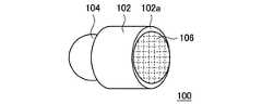
図1は、本発明の一実施形態に係る音響出力装置100の第1の構成例を示す模式図である。図1に示すように、音響出力装置100は、本体部102、イヤーピース(挿入部)104、指紋センサー106を有して構成されている。図1に示す例では、本体部102は円柱状とされ、本体部102の一端にユーザの耳穴に挿入されるイヤーピース104が設けられている。また、本体部102のイヤーピース104とは反対側の天面102aには、指紋センサー106が設けられている。2. 2. Configuration Example of Acoustic Output Device According to the Present Embodiment FIG. 1 is a schematic diagram showing a first configuration example of the
イヤーピース104は、ユーザの耳穴に挿入され、スピーカ(不図示)から耳穴に音を出力する。指紋センサー106は、撮像により得られた画像から指紋に関する指紋情報を検出する。また、指紋センサー106は、静電容量から指紋情報を検出するものであっても良い。画像から指紋情報を検出する光学式の場合、指紋情報は指紋の形状を表す画像情報である。また、静電容量から指紋情報を検出する静電式の場合、指紋情報は指紋の凹凸に応じた静電容量の情報である。また、指紋センサー106は、感熱式、電界式、圧力式など、他の方式により指紋を検出するものであっても良い。より具体的には、光学式は、プリズムやガラス面に指を置いて、指を置いた面の逆側から指の像をCCDカメラなどで撮像することで指紋情報を検出する。静電式は、指紋センサー106に指を押し付けた際に、指紋の山(指紋の紋様を形成する皮膚の盛り上がった部分)と谷の電荷量の違いによって指紋情報を得る方法である。感熱式は、指紋センサー106の表面に接触する指紋の山の部分の温度(体温)と谷の温度(空気温度)の温度差を検知から指紋情報を得る方法である。電界式は、指の表面に流した微弱電流で生じた、指紋の山の部分と谷の部分との電界の強度の差から生ずる分布パターンを指紋情報とする方法である。 The
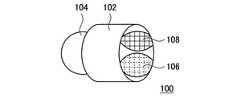
図2は、本実施形態に係る音響出力装置100の第2の構成例を示す模式図である。第2の構成例では、指紋センサー106が本体部102の円柱の側面に設けられている。また、本体部102のイヤーピース104とは反対側の天面102aには、通信アンテナ108が設けられている。通信アンテナ108は、Bluetooth(登録商標)などの通信方式により、音響出力装置100へ音声情報を送信する本体装置200と通信を行う。これにより、本体装置200が送信した音声情報を音響出力装置100が受信してイヤーピース104から音を出力し、ワイヤレスなイヤホンとして音響出力装置100を構成できる。なお、音響出力装置100は、イヤホン部にメモリ、CPU、バッテリーなどの全ての構成要素を備え、イヤホン部だけで完結する装置であっても良い。 FIG. 2 is a schematic diagram showing a second configuration example of the
図3は、本実施形態に係る音響出力装置100の第3の構成例を示す模式図である。第3の構成例では、通信アンテナ108が指紋センサー106とともに天面102aに設けられている。 FIG. 3 is a schematic diagram showing a third configuration example of the
図1~図3に示したように、本実施形態では、指紋センサー106を指で触り易い位置に設けている。利便性の面から、指紋センサー106は、イヤーピース104を耳穴に装着した際に、指が触れるよう外部に露出していなければならない。また、図2及び図3に示したように、音響出力装置100が通信デバイスを装備する機器の場合、干渉を避けるため通信アンテナ108を避けて指紋センサー106を配置することが望ましい。通信の干渉を避けるためには、通信アンテナ108と指紋センサー106が同一面(天面)に配置された図3の構成よりも、図2の構成の方がより有利である。 As shown in FIGS. 1 to 3, in the present embodiment, the
3.指紋検出による機能の実現
音響出力装置100は、ユーザの指紋情報と、指紋情報に対応する音響出力装置100の機能を紐付けて予め登録する。具体的には、登録したい指の指紋情報に実施させたい機能を割り当てる。これにより、両手の10本の指に対応して10機能を割り当てることが可能となる。例えば、図4に示すように、人差し指に音量のボリュームアップ(Volume Up)、中指にボリュームダウン(Volume Down)を割り当てることで、音響出力装置100は、ユーザの人差し指が指紋センサー106に触れた場合はボリュームアップを行い、ユーザの中指が指紋センサー106に触れた場合はボリュームダウンを行う。従って、ユーザは、2本の指で音量調整を行うことが可能となる。3. 3. Realization of a function by fingerprint detection The
なお、音楽再生に関連する操作だけでなく、音場を設定する機能や、その他の機能も割り当てることができる。更に、1本の指で異なる機能を同時に設定することもできる。図5は、人差し指に音声の再生開始(Play)を割り当てるとともに、ノイズキャンセル機能のオン、及びBluetooth(登録商標)のオンを割り当てた例を示している。図5の例によれば、ユーザの人差し指が指紋センサー106に触れると、音声の再生が開始されるとともに、ノイズキャンセル機能のオン、及びBluetooth(登録商標)のオンが行われる。従って、ユーザは、人差し指の指紋とこれらの機能を紐付けて予め登録しておくことで、人差し指を指紋センサー106に触れるだけで複数の機能を同時に実現することが可能となる。 In addition to operations related to music playback, functions for setting the sound field and other functions can also be assigned. Furthermore, different functions can be set at the same time with one finger. FIG. 5 shows an example in which the index finger is assigned to start playing voice (Play), the noise canceling function is turned on, and Bluetooth (registered trademark) is turned on. According to the example of FIG. 5, when the index finger of the user touches the
4.指紋情報と対応付けされる機能の例
以下では、指の指紋情報と対応付けすることが可能な音響出力装置100の機能の例を示す。なお、以下の機能は一例であって、他の機能と指紋情報を対応付けしても良い。
曲再生操作としては以下のものが挙げられる。
・再生/中断(Play/Pause)
・FF/FR
・ボリュームアップ/ボリュームダウン(Vol+/Vol-)
・電源オン(Power)
・リピート機能
・ホールド機能(Hold)
・Back/Up/Down
・シャッフル機能
・早送り/巻き戻し
・A/Bリピート4. Examples of Functions Associated with Fingerprint Information The following is an example of the functions of the
The following are examples of song playback operations.
-Play / Pause
・ FF / FR
・ Volume up / volume down (Vol + / Vol-)
・ Power on (Power)
・ Repeat function ・ Hold function (Hold)
・ Back / Up / Down
・ Shuffle function ・ Fast forward / rewind ・ A / B repeat
音場設定として以下のものが挙げられる。
・ソースダイレクト機能/イコライザ
・ノイズキャンセル
・外音モニター切り替え
・AVLS(Automatic Volume Limiter System)機能The following are examples of sound field settings.
-Source direct function / equalizer-Noise cancellation-External sound monitor switching-AVLS (Automatic Volume Limiter System) function
ファイル操作として以下のものが挙げられる。
・お気に入り機能(Bookmark機能)再生/登録
・フォルダ送り/戻し
・メニュー/Home機能
・Back
・アルバム・プレイリストの再生切り替え(表示を見られない為)The following are examples of file operations.
-Favorite function (Bookmark function) Play / Register-Folder forward / Return-Menu / Home function-Back
-Album / playlist playback switching (because you cannot see the display)
他機能と連携する操作として以下のものが挙げられる。
・マイク/通話
・録音
・音声入力
・カメラシャッター
・センサーOn/Off
・機器間認証
・動作モード切替
・トレーニングボタン
・音楽シェアボタン
・通知(バッテリ残量・曲名・メール・スケジュール等)The following are examples of operations that cooperate with other functions.
・ Microphone / Call ・ Recording ・ Voice input ・ Camera shutter ・ Sensor On / Off
・ Authentication between devices ・ Operation mode switching ・ Training button ・ Music share button ・ Notification (battery level, song title, email, schedule, etc.)
その他の機能に関する操作として以下のものが挙げられる。
・無線機器のペアリング
・リセット/設定初期化
・(イヤホン型で)個人認証The following are examples of operations related to other functions.
・ Pairing of wireless devices ・ Reset / Initialize settings ・ Personal authentication (with earphone type)
5.指紋認証処理について
図6は、指紋と機能を紐付けて登録する処理を示す模式図である。先ず、ステップS10では、指紋を音響出力装置100のメモリ(後述する指紋データベース116)に登録する。なお、指紋の登録は、音響出力装置100内への登録に限定されるものではなく、イヤーピース104を備える音響出力装置100側で検出した指紋情報を他の機器(スマートフォンなどの本体装置200、クラウドサーバなど)に送信し、他の機器側で指紋情報を登録しても良い。次のステップS12では、ステップS10で登録した指紋に割り当てる機能を選択する。次のステップS14では、ステップS10で登録した指紋の指紋情報とステップS12で選択した機能を紐付け、音響出力装置100のメモリに登録する。次のステップS16では、他の指紋に対しても登録するか否かを判定し、登録する場合はステップS10以降の処理を再度行う。一方、他の指紋に対して登録しない場合は、処理を終了する(END)。5. About fingerprint authentication process FIG. 6 is a schematic diagram showing a process of linking a fingerprint and a function and registering them. First, in step S10, the fingerprint is registered in the memory of the sound output device 100 (
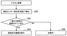
図7は、指紋に基づく機能実行の処理を示すフローチャートである。ユーザが音響出力装置100を耳に装着すると、先ずステップS20では、ユーザが指紋センサー106を指(指紋)で触る。これにより、指紋センサー106により指紋の情報が検出される。次のステップS22では、検出された指紋の情報と一致する指紋がメモリに登録されているか否かを判定し、登録されている場合はステップS24へ進む。ステップS24では、登録されている指紋に紐付けられた機能を実行する。一方、ステップS22において、検出された指紋の情報と一致する指紋が登録されていない場合は、ステップS26へ進む。ステップS26へ進んだ場合、音響出力装置100の機能は実行されない。指紋を音響出力装置100ではない他の機器に登録した場合は、音響出力装置100で検出した指紋情報を他の機器側へ送信することで、指紋認証は他の機器側で行い、認証結果を音響出力装置100へ送信する。 FIG. 7 is a flowchart showing a function execution process based on a fingerprint. When the user attaches the
6.音響出力装置の左耳用、右耳用の割り当て
通常のステレオ音声のためのイヤホンでは、左耳用と右耳用が予め決まっており、ユーザはイヤホンの表示を見て左耳用のイヤホンを左耳に挿入し、右耳用のイヤホンを右耳に挿入する。しかし、この方法では、ユーザがイヤホンを耳穴に挿入する前に、左耳用なのか右耳用なのかを確かめる必要があり、煩雑な手間が生じる。本実施形態では、左右の音響出力装置100の機能を指紋の情報に基づいて設定する際に、左右いずれの音声を出力するかを設定することができる。具体的には、左手の指紋が触った音響出力装置100には左耳用の音声を出力する機能が設定され、右手の指紋が触った音響出力装置100には右耳用の音声を出力する機能が設定される。従って、ユーザは左右の耳に音響出力装置100をそれぞれ挿入し、左手の指で左耳に挿入した音響出力装置100の指紋センサー106に触れるか、または右手の指で右耳に挿入した音響出力装置100の指紋センサー106に触れるのみで、左右の音響出力装置100から左右の耳のそれぞれに左耳用の音声と右耳用の音声を出力することができる。従って、音響出力装置100を左右の耳に挿入する際に、2つの音響出力装置100が左用なのか右用なのかを意識する必要がなく、煩雑な操作が不要となる。6. Assignment of the sound output device for the left ear and the right ear In the earphones for normal stereo sound, the one for the left ear and the one for the right ear are predetermined, and the user looks at the display of the earphone and selects the earphone for the left ear. Insert it into the left ear and insert the earphone for the right ear into the right ear. However, in this method, before the user inserts the earphone into the ear canal, it is necessary to confirm whether the earphone is for the left ear or the right ear, which causes troublesome work. In the present embodiment, when the functions of the left and right
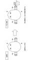
図8は、ユーザが音響出力装置100に指で触ることにより、左右の音響出力装置100の出力が左耳用の音声、右耳用の音声に設定される様子を示す模式図である。具体的には、先ず図8の左側の図に示すように、両耳それぞれに音響出力装置100を装着した時に、当初は左耳用と右耳用が不定の状態であるものとする。この状態から、図8の右側の図に示すように、ユーザが右手で右耳の音響出力装置100を触り、音響出力装置100に登録された右手の指紋のいずれかの情報と一致すると、右耳に装着された音響出力装置100は右耳用の音声を出力する個体として設定される。必然的に、左耳に装着された音響出力装置100は、左耳用の音声を出力する個体として設定される。これにより、イヤホンデバイスが左耳用であるか右耳用であるかを意識して装着する必要がなく、ユーザの利便性を大幅に高めることができる。 FIG. 8 is a schematic diagram showing how the outputs of the left and right
図9は、指紋センサー106の検出結果に基づいて、音響出力装置100が左耳用の音声を出力するか、または右耳用の音声を出力するかを設定する処理を示すフローチャートである。先ず、ステップS30では、ユーザが左右の耳に装着された2つの音響出力装置100の一方の指紋センサー106を指(指紋)で触る。これにより、指紋センサー106により指紋の情報が検出される。次のステップS32では、ステップS30で検出された指(指紋)が登録された右手の情報か否かを判定し、右手の情報である場合はステップS34へ進む。ステップS34では、ステップS30で触った音響出力装置100の出力を右耳用(Right)に設定する。次のステップS36では、ステップS30で触った音響出力装置100でない方の音響出力装置100の出力を左耳用に設定する。ステップS36の後はステップS38へ進み、登録先の機能を実行する。 FIG. 9 is a flowchart showing a process of setting whether the
また、ステップS32において、ステップS30で検出された指(指紋)が登録された右手の情報でない場合は、ステップS40へ進み、ステップS30で検出された指(指紋)が登録された左手の情報か否かを判定し、左手の情報である場合はステップS42へ進む。ステップS42では、ステップS30で触った音響出力装置100の出力を左耳用(Left)に設定する。次のステップS36では、ステップS30で触った音響出力装置100でない方の音響出力装置100の出力を右耳用に設定する。ステップS40において、ステップS30で検出された指(指紋)が登録された左手の情報でない場合は、ステップS44へ進み、動作を行わない。 Further, in step S32, if the finger (fingerprint) detected in step S30 is not the registered right hand information, the process proceeds to step S40, and the finger (fingerprint) detected in step S30 is the registered left hand information. It is determined whether or not it is, and if it is the information on the left hand, the process proceeds to step S42. In step S42, the output of the
以上のように、図9の処理によれば、右手で触った音響出力装置100からは右耳用の音声を出力し、他方の音響出力装置100からは左耳用の音声を出力する。また、左手で触った音響出力装置100からは左耳用の音声を出力し、他方の音響出力装置100からは右耳用の音声を出力する。従って、音響出力装置100が左耳用であるか右耳用であるかを意識して装着する必要がなく、ユーザの利便性を大幅に高めることができる。 As described above, according to the process of FIG. 9, the sound for the right ear is output from the
7.指紋情報と他のデバイスから得られる情報との組み合わせ
また、左右の個体を識別する他のデバイスと組み合わせれば、より確度を上げた左右判別が可能である。図9に示した手法は、ユーザの左手が左耳に装着された音響出力装置100に触れるか、またはユーザの右手が右耳に装着された音響出力装置100に触れることを前提としている。このため、仮にユーザの左手が右耳に装着された音響出力装置100に触れるようなことがあれば、右耳に装着された音響出力装置100から左耳用の音声が出力される事態が生じ得る。7. Combination of fingerprint information and information obtained from other devices In addition, by combining with other devices that identify left and right individuals, it is possible to make left-right discrimination with higher accuracy. The method shown in FIG. 9 assumes that the user's left hand touches the
図10は、音響出力装置100が重力センサーを有している場合を示している。図10に示すように、円柱状の本体部102の側面の一部に平面102bが設けられており、この平面102bがユーザの前方に向くように装着されることが予め定められているものとする。音響出力装置100が矢印A1で示す向きで右耳に装着されると、重力センサーが検出する重力の方向はZ軸の正方向である。矢印A1で示す向きが正しい装着位置であるとすると、音響出力装置100が矢印A2に示すように180°上下が反転した状態で左耳に装着されると、外観上は平面102bがユーザの前方に向いているが、重力センサーが検出する重力の方向はZ軸の負方向となるため、本来は右耳に装着されるべき音響出力装置100が左耳に装着されてしまったことが重力センサーの検出値から判別できる。 FIG. 10 shows a case where the
図10に示すような重力センサーを備えた音響出力装置100によれば、重力センサーが検出した重力の方向に基づいて、2つの音響出力装置100のそれぞれが左耳、右耳のいずれに装着されたかを判別することができる。従って、例えばユーザが左手の指紋を右耳に装着された音響出力装置100の指紋センサー106に触れた場合は、指紋センサー106のみで判別すると右耳に装着された音響出力装置100が左耳に装着されたものと判定されてしまうが、このような場合は重力センサーによる判定と併用することで、右耳に装着された音響出力装置100は右耳に装着されたものと判定することができ、右耳に装着された音響出力装置100から右耳用の音声を確実に出力することができる。 According to the
重力センサーを備えた音響出力装置100においても、上述したように「平面102bがユーザの前方に向くように装着される」といった取決めがない場合は、左耳、右耳のいずれに装着されたかを判別することはできない。つまり、重力センサーを備える音響出力装置100においても、本体部102は完全な円柱のような対称形状ではなく、非対称(アシンメトリー)な形状であって、形状と装着する方向に何らかの取決めが定められていることが必要である。 Even in the
8.非対称形状の本体部を有する音響出力装置の例
図11~図13は、非対称形状の本体部102を有する音響出力装置100の外観を示す模式図である。図11~図13に示す例では、天面102aとイヤーピース104の中心軸Cとのなす角θは90°ではなく、天面102aは中心軸Cに対して角度θだけ傾いている。これにより、図1に示す構成では指紋センサー106のセンサー面とイヤーピース104の中心軸が直交するが、図11~図13では指紋センサー106のセンサー面と中心軸Cが非垂直に構成される。一例として、音響出力装置100は、天面102aがユーザの後ろを向くように装着される。このような、中心軸Cに対して非対称な本体部102を有する音響出力装置100においても、指紋センサー106は、イヤーピース104を耳穴に装着した際に、指が触れるよう表面に露出した位置に配置される。図11は、天面102aに指紋センサー106を設けた例を、図12は本体部102の側面に指紋センサー106を設けた例を、図13は本体部の天面102aの一部に指紋センサー106を設けた例を示している。図13の場合、図3と同様に、天面102aに通信アンテナ108を設けることが可能である。8. Examples of an acoustic output device having an asymmetrical main body portion FIGS. 11 to 13 are schematic views showing the appearance of an
9.指紋センサーの本体部への配置の例
図14~図16は、指紋センサー106の本体部102への配置状態を示す模式図である。図14は、本体部102の凹部102c内に指紋センサー106を埋め込んだ例を示している。図14に示す構成によれば、ユーザの指が指紋センサー106の近傍に触れた際に、ユーザは凹部102cの触覚により指紋センサー106の位置を認識できる。従って、指紋センサー106上に指を確実に置くことが可能である。9. Examples of Arrangement of the Fingerprint Sensor on the Main Body: FIGS. 14 to 16 are schematic views showing a state in which the
また、図15は、本体部102の凸部102dの上に指紋センサーを配置した例を示している。図15に示す構成によれば、ユーザの指が指紋センサー106の近傍に触れた際に、ユーザは凸部102dの触覚により指紋センサー106の位置を認識できる。従って、指紋センサー106上に指を確実に置くことが可能である。 Further, FIG. 15 shows an example in which the fingerprint sensor is arranged on the convex portion 102d of the
また、図16は、本体部102に設けられた指紋センサー106の周囲に凸部102eを設けた例を示している。凸部102eは、本体部102と一体であっても良いし、本体部102と別部品で構成されていても良い。図16に示す構成によれば、ユーザの指が指紋センサー106の近傍に触れた際に、ユーザは凸部102eの触覚により指紋センサー106の位置を認識できる。従って、指紋センサー106上に指を確実に置くことが可能である。更に、凸部102eに指を検知するための別のセンサーを設けても良い。 Further, FIG. 16 shows an example in which a
10.音響出力装置の機能構成例
図17は、音響出力装置100の機能構成を示すブロック図である。図17に示すように、音響出力装置100は、指紋センサー104、指紋情報取得部110、指紋情報登録部112、機能選択情報取得部114、指紋データベース116、指紋照合部118、重力センサー119、通信部120、機能処理部130を有して構成されている。なお、図17に示す各構成要素は、ハードウェアまたはCPUなどの中央演算処理装置とこれを機能させるためのプログラム(ソフトウェア)から構成することができる。この場合に、そのプログラムは、音響出力装置100が備えるメモリ、または外部から接続されるメモリなどの記録媒体に格納されることができる。10. Example of Functional Configuration of Acoustic Output Device FIG. 17 is a block diagram showing a functional configuration of the
図17において、指紋情報取得部110は指紋センサー104から指紋情報を取得する。指紋情報登録部112は、図6のステップS10において、指紋情報を指紋データベース116に登録する。また、指紋情報登録部112は、図6のステップS14において、登録した指紋の指紋情報と機能を紐付けて指紋データベース116に登録する。機能選択情報取得部114は、図6のステップS12において、登録した指紋に割り当てるために選択された機能の情報を取得する。機能選択情報取得部114は、音響出力装置100または本体装置200に設けられた操作部をユーザが操作することによって選択された機能の情報を取得する。 In FIG. 17, the fingerprint
指紋照合部118は、図7のステップS22において、指紋センサー106で検出された指紋情報と指紋データベース116に登録された指紋情報を照合し、指紋センサー106で検出された指紋情報と一致する指紋情報が指紋データベース116に登録されているか否かを判定する。機能処理部は、図7のステップS24において、指紋センサー106で検出された指紋情報と一致する指紋情報が指紋データベース116に登録されている場合は、登録されている指紋情報に紐付けられた機能を実行する。 In step S22 of FIG. 7, the
通信部120は、本体装置200、または他の音響出力装置100と通信を行い、本体装置200または他の音響出力装置100と情報を共有する。通信は無線、有線のいずれであっても良い。無線通信を行う場合、通信部120は通信アンテナ108を介して本体装置200、または他の音響出力装置100と通信を行う。なお、他の音響出力装置100は、左右の耳に挿入される1つの音響出力装置100の他方である。例えば図9のステップS34で一方の音響出力装置100が右耳用に設定されると、次のステップS36において、他方の音響出力装置100は、一方の音響出力装置100が右耳用に設定されたことを通信部120を介して認識し、他方の音響出力装置100を左耳用に設定する。左耳用または右耳用の設定は、機能実行部130により行われる。左耳用に設定された音響出力装置100は本体装置200から左耳用の音声情報を受信し、右耳用に設定された音響出力装置100は本体装置200から右耳用の音声情報を受信する。 The
図17に示す構成要素のうち、音響出力装置100が指紋センサー104、重力センサー119、及び通信部120を備え、他の構成要素は本体装置200側に構成されることができる。この場合の構成を図18に示す。本体装置200に設けられた通信部140は音響出力装置100の通信部120と無線又は有線により通信を行い、本体装置200側に設けられた指紋情報取得部110が通信部120,140を介して指紋情報を取得し、本体装置200側で指紋情報の登録、照合、機能実行などの各処理を行う。 Among the components shown in FIG. 17, the
以上説明したように本実施形態によれば、耳穴に装着される音響出力装置100に指紋センサー106を設け、指紋情報と音響出力装置100の機能を紐付けて予め登録するようにした。そして、ユーザが指を指紋センサー106に当てた際に、登録された指紋情報と一致すれば、登録された指紋情報と紐付けられた機能を実行できるようにした。これにより、ユーザが指を指紋センサー106に当てるのみで所望の機能を実現することが可能となり、ユーザの利便性を大幅に向上することが可能となる。 As described above, according to the present embodiment, the
また、ユーザが機能を自由に設定できることにより、音響出力装置100のユニバーサルデザインが可能となり、右利き、左利きの双方に対応させることができる。また、操作部である指紋センサー106を小面積にすることで、動作の簡素化が可能となり、マルチファンクション化も可能とすることができる。また、機能ボタンを探す動作が無く、いつも同じ位置をタッチすることで機能を実行できるため、操作性を大幅に改善できる。 Further, since the user can freely set the function, the universal design of the
更に、指紋センサー106のみで操作を認識できるため、操作のためのスペースを最小限に抑えることができ、音響出力装置100の小型化が可能となる。また、指紋認証を行うことで、他人が使用することができなくなり、セキュリティ性を大幅に向上することができる。また、ユーザが指紋センサー106に触れるのみで機能を実行できるため、操作音を最小限に抑えることができ、タップやフリックする操作に比べて静粛性を大幅に多かK目ることが可能となる。 Further, since the operation can be recognized only by the
以上、添付図面を参照しながら本開示の好適な実施形態について詳細に説明したが、本開示の技術的範囲はかかる例に限定されない。本開示の技術分野における通常の知識を有する者であれば、特許請求の範囲に記載された技術的思想の範疇内において、各種の変更例または修正例に想到し得ることは明らかであり、これらについても、当然に本開示の技術的範囲に属するものと了解される。 Although the preferred embodiments of the present disclosure have been described in detail with reference to the accompanying drawings, the technical scope of the present disclosure is not limited to such examples. It is clear that anyone with ordinary knowledge in the art of the present disclosure may come up with various modifications or amendments within the scope of the technical ideas set forth in the claims. Is, of course, understood to belong to the technical scope of the present disclosure.
例えば、上記実施形態では、イヤホン型の音響出力装置を例示したが、本技術はかかる例に限定されない。例えば、音響出力装置としてオーバーヘッド型のヘッドホンに適用してもよい。 For example, in the above embodiment, an earphone type acoustic output device has been exemplified, but the present technology is not limited to such an example. For example, it may be applied to overhead headphones as an acoustic output device.
また、本明細書に記載された効果は、あくまで説明的または例示的なものであって限定的ではない。つまり、本開示に係る技術は、上記の効果とともに、または上記の効果に代えて、本明細書の記載から当業者には明らかな他の効果を奏しうる。 In addition, the effects described herein are merely explanatory or exemplary and are not limited. That is, the technique according to the present disclosure may exert other effects apparent to those skilled in the art from the description of the present specification, in addition to or in place of the above effects.
なお、以下のような構成も本開示の技術的範囲に属する。
(1) 耳穴に挿入されて耳穴に音を出力する挿入部と、
耳穴の外部に露出し、指紋情報を検出する指紋センサーと、
を備える、音響出力装置。
(2) 前記挿入部から連なり、耳穴の外部に露出する本体部を備え、
前記指紋センサーは、前記本体部に設けられた、前記(1)に記載の音響出力装置。
(3) 前記指紋センサーは、前記挿入部の耳穴への挿入方向と反対側の天面に設けられた、前記(2)に記載の音響出力装置。
(4) 前記挿入部の耳穴への挿入方向を表す中心軸と前記天面とが直交する、前記(3)に記載の音響出力装置。
(5) 前記挿入部の耳穴への挿入方向を表す中心軸と前記天面とが所定の角度で交わる、前記(3)に記載の音響出力装置。
(6) 前記天面に設けられた通信アンテナを備える、前記(3)~(5)のいずれかに記載の音響出力装置。
(7) 前記本体部は、前記挿入部の耳穴への挿入方向と反対側の天面を底面とする立体形状を成し、
前記指紋センサーは前記立体形状の側面に設けられた、前記(2)に記載の音響出力装置。
(8) 前記天面に設けられた通信アンテナを備える、前記(7)に記載の音響出力装置。
(9) 前記指紋センサーは、前記本体部の凹部内又は凸部上に設けられる、前記(2)~(8)のいずれかに記載の音響出力装置。
(10) 前記本体部には、前記指紋センサーの周囲を囲むように凸部が設けられた、前記(2)~(8)のいずれかに記載の音響出力装置。
(11) 指紋情報と所定の機能を紐付けて予め登録するデータベースと、
前記指紋センサーによって検出された前記指紋情報と前記データベースに登録された前記指紋情報を照合する指紋照合部と、
前記指紋照合部による照合の結果、前記指紋センサーによって検出された前記指紋情報と前記データベースに登録された前記指紋情報が一致する場合に、前記データベースに登録された前記指紋情報に紐付けられた前記所定の機能を実行する機能実行部と、
を更に備える、前記(1)~(10)のいずれかに記載の音響出力装置。
(12) 前記所定の機能は、少なくとも音響の出力に関する機能を含む、前記(11)に記載の音響出力装置。
(13) 前記データベースは、1の指紋情報に複数の前記所定の機能を紐付けて予め登録し、
前記機能実行部は、前記指紋照合部による照合の結果、前記指紋センサーによって検出された前記指紋情報と前記データベースに登録された前記指紋情報が一致する場合に、前記データベースに登録された前記指紋情報に紐付けられた複数の前記所定の機能を実行する、前記(11)又は(12)に記載の音響出力装置。
(14) 前記指紋照合部は、前記指紋センサーによって検出された前記指紋情報と前記データベースに登録された前記指紋情報を照合することで、前記指紋センサーによって検出された前記指紋情報が左右いずれの手の指紋情報であるかを認識し、
前記機能実行部は、前記指紋照合部による照合の結果に基づいて、前記指紋センサーによって検出された前記指紋情報が左右いずれの手の指紋情報であるかに応じて、左耳用又は右耳用の音を耳穴に出力する機能を実行する、前記(11)又は(12)に記載の音響出力装置。
(15) 重力センサーを備え、
前記機能実行部は、前記重力センサーによって検出される重力の方向から得られる情報に基づいて、左耳用又は右耳用の音を耳穴に出力する機能を実行する、前記(14)に記載の音響出力装置。
(16) 指紋情報と所定の機能を紐付けてデータベースに予め登録することと、
耳穴に挿入される音響出力装置に設けられた指紋センサーによって検出された指紋情報と前記データベースに登録された前記指紋情報を照合することと、
前記照合の結果、前記指紋センサーによって検出された前記指紋情報と前記データベースに登録された前記指紋情報が一致する場合に、前記データベースに登録された前記指紋情報に紐付けられた前記所定の機能を実行することと、
を備える、音響出力装置の機能実行方法。
(17) 指紋情報と所定の機能を紐付けてデータベースに予め登録する手段、
耳穴に挿入される音響出力装置に設けられた指紋センサーによって検出された指紋情報と前記データベースに登録された前記指紋情報を照合する手段、
前記照合の結果、前記指紋センサーによって検出された前記指紋情報と前記データベースに登録された前記指紋情報が一致する場合に、前記データベースに登録された前記指紋情報に紐付けられた前記所定の機能を実行する手段、
としてコンピュータを機能させるためのプログラム。The following configurations also belong to the technical scope of the present disclosure.
(1) An insertion part that is inserted into the ear canal and outputs sound to the ear canal,
A fingerprint sensor that is exposed to the outside of the ear canal and detects fingerprint information,
Equipped with an acoustic output device.
(2) A main body that is continuous from the insertion part and is exposed to the outside of the ear canal is provided.
The acoustic output device according to (1), wherein the fingerprint sensor is provided in the main body.
(3) The acoustic output device according to (2) above, wherein the fingerprint sensor is provided on the top surface opposite to the insertion direction of the insertion portion into the ear canal.
(4) The acoustic output device according to (3) above, wherein the central axis indicating the insertion direction of the insertion portion into the ear canal and the top surface are orthogonal to each other.
(5) The acoustic output device according to (3) above, wherein the central axis indicating the insertion direction of the insertion portion into the ear canal and the top surface intersect at a predetermined angle.
(6) The acoustic output device according to any one of (3) to (5) above, which comprises a communication antenna provided on the top surface.
(7) The main body has a three-dimensional shape with the top surface on the side opposite to the insertion direction of the insertion portion into the ear canal as the bottom surface.
The acoustic output device according to (2) above, wherein the fingerprint sensor is provided on the side surface of the three-dimensional shape.
(8) The acoustic output device according to (7) above, which comprises a communication antenna provided on the top surface.
(9) The acoustic output device according to any one of (2) to (8) above, wherein the fingerprint sensor is provided in a concave portion or a convex portion of the main body portion.
(10) The acoustic output device according to any one of (2) to (8) above, wherein the main body is provided with a convex portion so as to surround the periphery of the fingerprint sensor.
(11) A database that associates fingerprint information with a predetermined function and registers it in advance,
A fingerprint collation unit that collates the fingerprint information detected by the fingerprint sensor with the fingerprint information registered in the database.
When the fingerprint information detected by the fingerprint sensor and the fingerprint information registered in the database match as a result of collation by the fingerprint collation unit, the fingerprint information linked to the fingerprint information registered in the database is linked. A function execution unit that executes a predetermined function, and
The acoustic output device according to any one of (1) to (10) above.
(12) The acoustic output device according to (11) above, wherein the predetermined function includes at least a function related to acoustic output.
(13) In the database, one fingerprint information is associated with a plurality of the predetermined functions and registered in advance.
When the fingerprint information detected by the fingerprint sensor and the fingerprint information registered in the database match as a result of the collation by the fingerprint collation unit, the function executing unit has the fingerprint information registered in the database. The acoustic output device according to (11) or (12), which performs the plurality of predetermined functions associated with the above.
(14) The fingerprint collating unit collates the fingerprint information detected by the fingerprint sensor with the fingerprint information registered in the database, so that the fingerprint information detected by the fingerprint sensor is on either the left or right hand. Recognize whether it is fingerprint information of
The function executing unit is for the left ear or the right ear depending on whether the fingerprint information detected by the fingerprint sensor is the fingerprint information of the left or right hand based on the result of the collation by the fingerprint collating unit. The acoustic output device according to (11) or (12) above, which executes the function of outputting the sound of the above to the ear canal.
(15) Equipped with a gravity sensor
The function executing unit executes the function of outputting the sound for the left ear or the right ear to the ear canal based on the information obtained from the direction of gravity detected by the gravity sensor, according to the above (14). Sound output device.
(16) Pre-registering fingerprint information with a predetermined function in the database,
Collating the fingerprint information detected by the fingerprint sensor provided in the acoustic output device inserted into the ear canal with the fingerprint information registered in the database, and
When the fingerprint information detected by the fingerprint sensor and the fingerprint information registered in the database match as a result of the collation, the predetermined function associated with the fingerprint information registered in the database is performed. To do and
How to execute the function of the acoustic output device.
(17) A means of linking fingerprint information and a predetermined function and pre-registering them in a database.
A means for collating the fingerprint information detected by the fingerprint sensor provided in the acoustic output device inserted into the ear canal with the fingerprint information registered in the database.
When the fingerprint information detected by the fingerprint sensor and the fingerprint information registered in the database match as a result of the collation, the predetermined function associated with the fingerprint information registered in the database is performed. Means to do,
A program to make your computer work as.
100 音響出力装置
102 本体部
102a 天面
104 イヤーピース
106 指紋センサー
108 通信アンテナ
116 指紋データベース
118 指紋照合部
119 重力センサー
130 機能実行部100
Claims (12)
Translated fromJapanese前記挿入部から連なり、前記挿入部の耳穴への挿入方向と反対側の天面を底面とする円柱状の立体形状を成し、耳穴の外部に露出する本体部と、
前記本体部に設けられた、指紋情報を検出する指紋センサーと、
前記天面に設けられた通信アンテナと、
を備え、
前記指紋センサーは、前記立体形状の前記挿入部側と前記天面側のうち、中央よりも前記天面に近い側の側面に設けられる、
音響出力装置。An insertion part that is inserted into the ear canal and outputs sound to the ear canal,
A main body that is continuous from the insertion portion and has a columnar three-dimensional shape with the top surface opposite to the insertion direction of the insertion portion into the ear canal as the bottom surface, and is exposed to the outside of the ear canal.
A fingerprint sensor for detecting fingerprint informationprovided on the main body ,
The communication antenna provided on the top surface and
Equippedwith
The fingerprint sensor is provided on the side surface of the three-dimensional shape of the insertion portion side and the top surface side, which is closer to the top surface than the center.
Acoustic output device.
前記指紋センサーによって検出された前記指紋情報と前記データベースに登録された前記指紋情報を照合する指紋照合部と、
前記指紋照合部による照合の結果、前記指紋センサーによって検出された前記指紋情報と前記データベースに登録された前記指紋情報が一致する場合に、前記データベースに登録された前記指紋情報に紐付けられた前記所定の機能を実行する機能実行部と、
を更に備える、請求項1に記載の音響出力装置。A database that associates fingerprint information with a predetermined function and registers it in advance,
A fingerprint collation unit that collates the fingerprint information detected by the fingerprint sensor with the fingerprint information registered in the database.
When the fingerprint information detected by the fingerprint sensor and the fingerprint information registered in the database match as a result of collation by the fingerprint collation unit, the fingerprint information linked to the fingerprint information registered in the database is linked. A function execution unit that executes a predetermined function, and
The acoustic output device according to claim 1, further comprising.
前記機能実行部は、前記指紋照合部による照合の結果、前記指紋センサーによって検出された前記指紋情報と前記データベースに登録された前記指紋情報が一致する場合に、前記データベースに登録された前記指紋情報に紐付けられた複数の前記所定の機能を実行する、請求項6に記載の音響出力装置。In the database, one fingerprint information is associated with a plurality of the predetermined functions and registered in advance.
When the fingerprint information detected by the fingerprint sensor and the fingerprint information registered in the database match as a result of the collation by the fingerprint collation unit, the function executing unit has the fingerprint information registered in the database. The acoustic output device according to claim6 , which performs the plurality of predetermined functions associated with the above.
前記機能実行部は、前記指紋照合部による照合の結果に基づいて、前記指紋センサーによって検出された前記指紋情報が左右いずれの手の指紋情報であるかに応じて、左耳用又は右耳用の音を耳穴に出力する機能を実行する、請求項6に記載の音響出力装置。The fingerprint collating unit collates the fingerprint information detected by the fingerprint sensor with the fingerprint information registered in the database, and the fingerprint information detected by the fingerprint sensor is the fingerprint information of either the left or right hand. Recognize if
The function executing unit is for the left ear or the right ear depending on whether the fingerprint information detected by the fingerprint sensor is the fingerprint information of the left or right hand based on the result of the collation by the fingerprint collating unit. The acoustic output device according to claim6 , which executes a function of outputting the sound of.
前記機能実行部は、前記重力センサーによって検出される重力の方向から得られる情報に基づいて、左耳用又は右耳用の音を耳穴に出力する機能を実行する、請求項9に記載の音響出力装置。Equipped with a gravity sensor,
The acoustic according to claim9 , wherein the function executing unit executes a function of outputting a sound for the left ear or a sound for the right ear to the ear canal based on the information obtained from the direction of gravity detected by the gravity sensor. Output device.
挿入部と、前記挿入部から連なり、前記挿入部の耳穴への挿入方向と反対側の天面を底面とする円柱状の立体形状を成して耳穴の外部に露出する本体部と、前記天面に設けられた通信アンテナとを備える音響出力装置に設けられた指紋センサーであって、前記立体形状の前記挿入部側と前記天面側のうち、中央よりも前記天面に近い側の側面に設けられる指紋センサーによって検出された指紋情報と、前記データベースに登録された前記指紋情報とを照合することと、
前記照合の結果、前記指紋センサーによって検出された前記指紋情報と前記データベースに登録された前記指紋情報が一致する場合に、前記データベースに登録された前記指紋情報に紐付けられた前記所定の機能を実行することと、
を備える、前記音響出力装置の機能実行方法。Pre-registering the fingerprint information and the specified function in the database,
The insertion part, the main body part that is connected to the insertion part and is exposed to the outside of the ear canal in a columnar three-dimensional shape with the top surface opposite to the insertion direction of the insertion part into the ear canal as the bottom surface, and the heaven A fingerprint sensor provided in an acoustic output device provided with a communication antenna provided on a surface, which is a side surface of the three-dimensional shape of the insertion portion side and the top surface side, which is closer to the top surface than the center. By collating the fingerprint information detected by the fingerprint sensorprovided in the abovewiththe fingerprint information registered in the database,
When the fingerprint information detected by the fingerprint sensor and the fingerprint information registered in the database match as a result of the collation, the predetermined function associated with the fingerprint information registered in the database is performed. To do and
A method for executing a function ofthe acoustic output device.
挿入部と、前記挿入部から連なり、前記挿入部の耳穴への挿入方向と反対側の天面を底面とする円柱状の立体形状を成して耳穴の外部に露出する本体部と、前記天面に設けられた通信アンテナと、を備える音響出力装置に設けられた指紋センサーであって、前記立体形状の前記挿入部側と前記天面側のうち、中央よりも前記天面に近い側の側面に設けられる指紋センサーによって検出された指紋情報と、前記データベースに登録された前記指紋情報とを照合する手段、
前記照合の結果、前記指紋センサーによって検出された前記指紋情報と前記データベースに登録された前記指紋情報が一致する場合に、前記データベースに登録された前記指紋情報に紐付けられた前記所定の機能を実行する手段、
としてコンピュータを機能させるためのプログラム。A means of linking fingerprint information with a predetermined function and pre-registering it in a database,
The insertion part, the main body part that is connected to the insertion part and is exposed to the outside of the ear canal in a columnar three-dimensional shape with the top surface opposite to the insertion direction of the insertion part into the ear canal as the bottom surface, and the heaven A fingerprint sensor provided in an acoustic output device including a communication antenna provided on a surface, which is closer to the top surface than the center of the insertion portion side and the top surface side of the three-dimensional shape. Ameans for collating the fingerprint information detected by the fingerprint sensorprovided on the side surface withthe fingerprint information registered in the database.
When the fingerprint information detected by the fingerprint sensor and the fingerprint information registered in the database match as a result of the collation, the predetermined function associated with the fingerprint information registered in the database is performed. Means to do,
A program to make your computer work as.
Applications Claiming Priority (3)
| Application Number | Priority Date | Filing Date | Title |
|---|---|---|---|
| JP2016207695 | 2016-10-24 | ||
| JP2016207695 | 2016-10-24 | ||
| PCT/JP2017/033985WO2018079139A1 (en) | 2016-10-24 | 2017-09-20 | Sound output device, method for executing function of sound output device, and program |
Publications (2)
| Publication Number | Publication Date |
|---|---|
| JPWO2018079139A1 JPWO2018079139A1 (en) | 2019-09-12 |
| JP7040458B2true JP7040458B2 (en) | 2022-03-23 |
Family
ID=62024780
Family Applications (1)
| Application Number | Title | Priority Date | Filing Date |
|---|---|---|---|
| JP2018547196AActiveJP7040458B2 (en) | 2016-10-24 | 2017-09-20 | Sound output device, function execution method and program of sound output device |
Country Status (5)
| Country | Link |
|---|---|
| US (1) | US10812891B2 (en) |
| EP (1) | EP3531712A4 (en) |
| JP (1) | JP7040458B2 (en) |
| KR (1) | KR102347270B1 (en) |
| WO (1) | WO2018079139A1 (en) |
Families Citing this family (13)
| Publication number | Priority date | Publication date | Assignee | Title |
|---|---|---|---|---|
| US9285886B2 (en) | 2013-06-24 | 2016-03-15 | Sonos, Inc. | Intelligent amplifier activation |
| EP3220668A1 (en)* | 2016-03-15 | 2017-09-20 | Thomson Licensing | Method for configuring an audio rendering and/or acquiring device, and corresponding audio rendering and/or acquiring device, system, computer readable program product and computer readable storage medium |
| EP3599644B1 (en)* | 2018-07-26 | 2020-08-19 | PA.Cotte Family Holding GmbH | Multifunctional display |
| CN113242719A (en)* | 2018-12-19 | 2021-08-10 | 日本电气株式会社 | Information processing apparatus, wearable apparatus, information processing method, and storage medium |
| KR102684330B1 (en)* | 2019-04-08 | 2024-07-11 | 엘에스일렉트릭(주) | Monitoring device of contacting point for a vacuum circuit breaker and vacuum circuit breaker having it |
| USD888021S1 (en)* | 2019-06-27 | 2020-06-23 | Jose Luis Telle | Faraday shield for loud speakers |
| US20220225007A1 (en)* | 2019-07-22 | 2022-07-14 | Hewlett-Packard Development Company, L.P. | Headphones |
| JP2021027569A (en)* | 2019-08-09 | 2021-02-22 | 株式会社Jvcケンウッド | Wireless earphone |
| JP6729957B1 (en)* | 2019-11-01 | 2020-07-29 | 株式会社ネイン | Management system, management method, and computer program |
| CN111031432A (en)* | 2019-12-20 | 2020-04-17 | 歌尔股份有限公司 | Neck-wearing earphone, function switching method, system, device and computer medium |
| CN111464908B (en)* | 2020-04-28 | 2023-04-07 | 歌尔科技有限公司 | Earphone and earphone control method |
| CN111586549B (en)* | 2020-05-14 | 2022-03-15 | 昆明闻泰通讯有限公司 | Earphone insertion detection circuit |
| CN111780907A (en)* | 2020-07-06 | 2020-10-16 | 歌尔科技有限公司 | Earphone, earphone state monitoring method and device and readable storage medium |
Citations (6)
| Publication number | Priority date | Publication date | Assignee | Title |
|---|---|---|---|---|
| JP2004363671A (en) | 2003-06-02 | 2004-12-24 | Sharp Corp | Portable music player |
| US20090041313A1 (en) | 2007-08-10 | 2009-02-12 | Plantronics, Inc. | User validation of body worn device |
| US20090087004A1 (en) | 2007-09-28 | 2009-04-02 | Siemens Audiologische Technik Gmbh | Operating device for a hearing aid |
| JP2014143451A (en) | 2011-05-10 | 2014-08-07 | Japan Science & Technology Agency | Stereo headphone device |
| US20150312669A1 (en) | 2011-06-29 | 2015-10-29 | Lg Electronics Inc. | Terminal and control method thereof |
| CN105848031A (en) | 2016-03-31 | 2016-08-10 | 乐视控股(北京)有限公司 | Earphone sound channel adjusting method and device |
Family Cites Families (16)
| Publication number | Priority date | Publication date | Assignee | Title |
|---|---|---|---|---|
| BR9809845A (en) | 1998-03-30 | 2000-06-20 | Enix Corporetion | Information recording / processing devices and machine / system control devices, equipped with fingerprint sensors |
| US6282304B1 (en) | 1999-05-14 | 2001-08-28 | Biolink Technologies International, Inc. | Biometric system for biometric input, comparison, authentication and access control and method therefor |
| JP3951920B2 (en) | 2001-02-09 | 2007-08-01 | ソニー株式会社 | Input device |
| US20060093192A1 (en)* | 2004-11-03 | 2006-05-04 | Bechtel J S | Finger guide device |
| US20100311390A9 (en) | 2006-03-20 | 2010-12-09 | Black Gerald R | Mobile communication device |
| CA2647194C (en) | 2006-03-20 | 2016-08-16 | Gerald R. Black | Mobile communication device |
| JP2008182509A (en)* | 2007-01-25 | 2008-08-07 | Funai Electric Co Ltd | Headphone device and wireless headphone system |
| US20090010461A1 (en)* | 2007-07-02 | 2009-01-08 | Gunnar Klinghult | Headset assembly for a portable mobile communications device |
| US8655000B1 (en)* | 2009-06-12 | 2014-02-18 | Starkey Laboratories, Inc. | Method and apparatus for a finger sensor for a hearing assistance device |
| US20130279724A1 (en)* | 2012-04-19 | 2013-10-24 | Sony Computer Entertainment Inc. | Auto detection of headphone orientation |
| NO336008B1 (en)* | 2013-06-26 | 2015-04-20 | Steinar Pedersen | Easy and reliable authentication of fingerprints |
| US9924270B2 (en)* | 2015-01-09 | 2018-03-20 | Intel Corporation | Techniques for channelization of stereo audio in headphones |
| US9866282B2 (en)* | 2015-08-29 | 2018-01-09 | Bragi GmbH | Magnetic induction antenna for use in a wearable device |
| US9706304B1 (en)* | 2016-03-29 | 2017-07-11 | Lenovo (Singapore) Pte. Ltd. | Systems and methods to control audio output for a particular ear of a user |
| US10747337B2 (en)* | 2016-04-26 | 2020-08-18 | Bragi GmbH | Mechanical detection of a touch movement using a sensor and a special surface pattern system and method |
| US10013542B2 (en)* | 2016-04-28 | 2018-07-03 | Bragi GmbH | Biometric interface system and method |
- 2017
- 2017-09-20JPJP2018547196Apatent/JP7040458B2/enactiveActive
- 2017-09-20EPEP17863906.8Apatent/EP3531712A4/ennot_activeWithdrawn
- 2017-09-20USUS16/330,806patent/US10812891B2/enactiveActive
- 2017-09-20WOPCT/JP2017/033985patent/WO2018079139A1/ennot_activeCeased
- 2017-09-20KRKR1020197010593Apatent/KR102347270B1/enactiveActive
Patent Citations (6)
| Publication number | Priority date | Publication date | Assignee | Title |
|---|---|---|---|---|
| JP2004363671A (en) | 2003-06-02 | 2004-12-24 | Sharp Corp | Portable music player |
| US20090041313A1 (en) | 2007-08-10 | 2009-02-12 | Plantronics, Inc. | User validation of body worn device |
| US20090087004A1 (en) | 2007-09-28 | 2009-04-02 | Siemens Audiologische Technik Gmbh | Operating device for a hearing aid |
| JP2014143451A (en) | 2011-05-10 | 2014-08-07 | Japan Science & Technology Agency | Stereo headphone device |
| US20150312669A1 (en) | 2011-06-29 | 2015-10-29 | Lg Electronics Inc. | Terminal and control method thereof |
| CN105848031A (en) | 2016-03-31 | 2016-08-10 | 乐视控股(北京)有限公司 | Earphone sound channel adjusting method and device |
Also Published As
| Publication number | Publication date |
|---|---|
| US20190238969A1 (en) | 2019-08-01 |
| WO2018079139A1 (en) | 2018-05-03 |
| KR20190069423A (en) | 2019-06-19 |
| KR102347270B1 (en) | 2022-01-06 |
| EP3531712A1 (en) | 2019-08-28 |
| US10812891B2 (en) | 2020-10-20 |
| EP3531712A4 (en) | 2020-03-25 |
| JPWO2018079139A1 (en) | 2019-09-12 |
Similar Documents
| Publication | Publication Date | Title |
|---|---|---|
| JP7040458B2 (en) | Sound output device, function execution method and program of sound output device | |
| JP7274527B2 (en) | Change companion communication device behavior based on wearable device state | |
| US10942615B2 (en) | Reconfigurable clip-on modules for mobile computing devices | |
| CN105009040B (en) | Terminal device, control method and program for terminal device | |
| US20150280763A1 (en) | Mobile terminal | |
| CN106210954B (en) | Headphone-based terminal device control method and headphone | |
| KR20160136013A (en) | Mobile terminal and method for controlling the same | |
| US10579260B2 (en) | Mobile terminal having display screen and communication system thereof for unlocking connected devices using an operation pattern | |
| KR20160029524A (en) | Electronic device and system comprising it | |
| KR102643055B1 (en) | Headset Electronic Device and Electronic Device Connecting the Same | |
| WO2017060900A1 (en) | Communicating bracelet | |
| US11252831B2 (en) | Electronic device including opening | |
| WO2018116678A1 (en) | Information processing device and method for control thereof | |
| KR20200022942A (en) | An electronic device comprising key assembly including pressure sensor and a operation method thereof | |
| TWI735171B (en) | Setup method, recognition method and electronic device using the same | |
| EP4055807B1 (en) | Electronic device including camera and method of operating the same | |
| WO2023063407A1 (en) | Information processing system, information processing device and method, accommodation case, information processing method, and program | |
| WO2025201284A1 (en) | Earphone left- and right-channel matching method, ear clip earphones, and storage medium | |
| KR20210027964A (en) | Electronic device including input device | |
| HK40040590B (en) | Reconfigurable clip-on modules for mobile computing devices | |
| KR20210045154A (en) | Electronic device and method for operating key of electronic device according to key input thereof | |
| WO2023051750A1 (en) | Data processing method and related device | |
| HK40040590A (en) | Reconfigurable clip-on modules for mobile computing devices |
Legal Events
| Date | Code | Title | Description |
|---|---|---|---|
| RD02 | Notification of acceptance of power of attorney | Free format text:JAPANESE INTERMEDIATE CODE: A7422 Effective date:20190515 | |
| RD04 | Notification of resignation of power of attorney | Free format text:JAPANESE INTERMEDIATE CODE: A7424 Effective date:20190522 | |
| A621 | Written request for application examination | Free format text:JAPANESE INTERMEDIATE CODE: A621 Effective date:20200915 | |
| A131 | Notification of reasons for refusal | Free format text:JAPANESE INTERMEDIATE CODE: A131 Effective date:20210907 | |
| A521 | Request for written amendment filed | Free format text:JAPANESE INTERMEDIATE CODE: A523 Effective date:20211028 | |
| TRDD | Decision of grant or rejection written | ||
| A01 | Written decision to grant a patent or to grant a registration (utility model) | Free format text:JAPANESE INTERMEDIATE CODE: A01 Effective date:20220208 | |
| A61 | First payment of annual fees (during grant procedure) | Free format text:JAPANESE INTERMEDIATE CODE: A61 Effective date:20220221 | |
| R151 | Written notification of patent or utility model registration | Ref document number:7040458 Country of ref document:JP Free format text:JAPANESE INTERMEDIATE CODE: R151 |