JP7036509B2 - Optical direction changing film structure and its manufacturing method - Google Patents
Optical direction changing film structure and its manufacturing methodDownload PDFInfo
- Publication number
- JP7036509B2 JP7036509B2JP2018560088AJP2018560088AJP7036509B2JP 7036509 B2JP7036509 B2JP 7036509B2JP 2018560088 AJP2018560088 AJP 2018560088AJP 2018560088 AJP2018560088 AJP 2018560088AJP 7036509 B2JP7036509 B2JP 7036509B2
- Authority
- JP
- Japan
- Prior art keywords
- film
- film structure
- main surface
- peak
- structure according
- Prior art date
- Legal status (The legal status is an assumption and is not a legal conclusion. Google has not performed a legal analysis and makes no representation as to the accuracy of the status listed.)
- Active
Links
- 230000003287optical effectEffects0.000titleclaimsdescription187
- 238000004519manufacturing processMethods0.000titledescription11
- 239000010408filmSubstances0.000claimsdescription1458
- 230000001070adhesive effectEffects0.000claimsdescription306
- 239000000853adhesiveSubstances0.000claimsdescription305
- 239000012790adhesive layerSubstances0.000claimsdescription240
- 239000013039cover filmSubstances0.000claimsdescription185
- 230000008859changeEffects0.000claimsdescription158
- 239000003795chemical substances by applicationSubstances0.000claimsdescription103
- 239000002105nanoparticleSubstances0.000claimsdescription33
- 239000011325microbeadSubstances0.000claimsdescription24
- 239000010410layerSubstances0.000description147
- 239000000463materialSubstances0.000description140
- 238000009792diffusion processMethods0.000description65
- 238000000576coating methodMethods0.000description61
- 239000011248coating agentSubstances0.000description55
- 239000012788optical filmSubstances0.000description45
- 239000004820Pressure-sensitive adhesiveSubstances0.000description38
- 239000000758substrateSubstances0.000description37
- 238000000034methodMethods0.000description30
- 230000004313glareEffects0.000description27
- 238000002834transmittanceMethods0.000description27
- 238000006243chemical reactionMethods0.000description24
- 229920005989resinPolymers0.000description22
- 239000002245particleSubstances0.000description21
- 230000005855radiationEffects0.000description21
- 239000011347resinSubstances0.000description21
- 239000011324beadSubstances0.000description19
- 230000008569processEffects0.000description18
- 239000000203mixtureSubstances0.000description17
- 239000000178monomerSubstances0.000description16
- 229920000139polyethylene terephthalatePolymers0.000description16
- 230000006870functionEffects0.000description15
- 238000005259measurementMethods0.000description14
- 230000004927fusionEffects0.000description13
- NIXOWILDQLNWCW-UHFFFAOYSA-Nacrylic acid groupChemical groupC(C=C)(=O)ONIXOWILDQLNWCW-UHFFFAOYSA-N0.000description12
- 229920000642polymerPolymers0.000description12
- 230000010076replicationEffects0.000description12
- 238000007789sealingMethods0.000description12
- 238000010030laminatingMethods0.000description11
- 229910000831SteelInorganic materials0.000description10
- 239000000565sealantSubstances0.000description10
- 239000010959steelSubstances0.000description10
- 230000003746surface roughnessEffects0.000description10
- NIXOWILDQLNWCW-UHFFFAOYSA-MAcrylateChemical compound[O-]C(=O)C=CNIXOWILDQLNWCW-UHFFFAOYSA-M0.000description8
- 239000000654additiveSubstances0.000description8
- 238000004132cross linkingMethods0.000description8
- 229920000728polyesterPolymers0.000description8
- 238000012360testing methodMethods0.000description8
- 239000000326ultraviolet stabilizing agentSubstances0.000description8
- 238000001723curingMethods0.000description7
- 230000000694effectsEffects0.000description7
- 229920001971elastomerPolymers0.000description7
- 239000005060rubberSubstances0.000description7
- 239000002904solventSubstances0.000description7
- 239000004831Hot glueSubstances0.000description6
- VYPSYNLAJGMNEJ-UHFFFAOYSA-NSilicium dioxideChemical compoundO=[Si]=OVYPSYNLAJGMNEJ-UHFFFAOYSA-N0.000description6
- MCMNRKCIXSYSNV-UHFFFAOYSA-NZirconium dioxideChemical compoundO=[Zr]=OMCMNRKCIXSYSNV-UHFFFAOYSA-N0.000description6
- 239000006096absorbing agentSubstances0.000description6
- 150000001252acrylic acid derivativesChemical class0.000description6
- 238000005286illuminationMethods0.000description6
- -1polyethylenePolymers0.000description6
- JLZIIHMTTRXXIN-UHFFFAOYSA-N2-(2-hydroxy-4-methoxybenzoyl)benzoic acidChemical compoundOC1=CC(OC)=CC=C1C(=O)C1=CC=CC=C1C(O)=OJLZIIHMTTRXXIN-UHFFFAOYSA-N0.000description5
- 238000003848UV Light-CuringMethods0.000description5
- 229910052782aluminiumInorganic materials0.000description5
- XAGFODPZIPBFFR-UHFFFAOYSA-NaluminiumChemical compound[Al]XAGFODPZIPBFFR-UHFFFAOYSA-N0.000description5
- 238000013461designMethods0.000description5
- 230000000149penetrating effectEffects0.000description5
- 229920001296polysiloxanePolymers0.000description5
- 150000003254radicalsChemical class0.000description5
- 239000013557residual solventSubstances0.000description5
- 239000000126substanceSubstances0.000description5
- 229920001187thermosetting polymerPolymers0.000description5
- 230000000996additive effectEffects0.000description4
- 230000007423decreaseEffects0.000description4
- 238000001035dryingMethods0.000description4
- 150000002148estersChemical class0.000description4
- 239000007787solidSubstances0.000description4
- SMZOUWXMTYCWNB-UHFFFAOYSA-N2-(2-methoxy-5-methylphenyl)ethanamineChemical compoundCOC1=CC=C(C)C=C1CCNSMZOUWXMTYCWNB-UHFFFAOYSA-N0.000description3
- IYAZLDLPUNDVAG-UHFFFAOYSA-N2-(benzotriazol-2-yl)-4-(2,4,4-trimethylpentan-2-yl)phenolChemical compoundCC(C)(C)CC(C)(C)C1=CC=C(O)C(N2N=C3C=CC=CC3=N2)=C1IYAZLDLPUNDVAG-UHFFFAOYSA-N0.000description3
- DXPPIEDUBFUSEZ-UHFFFAOYSA-N6-methylheptyl prop-2-enoateChemical compoundCC(C)CCCCCOC(=O)C=CDXPPIEDUBFUSEZ-UHFFFAOYSA-N0.000description3
- RSWGJHLUYNHPMX-UHFFFAOYSA-NAbietic-SaeureNatural productsC12CCC(C(C)C)=CC2=CCC2C1(C)CCCC2(C)C(O)=ORSWGJHLUYNHPMX-UHFFFAOYSA-N0.000description3
- HRPVXLWXLXDGHG-UHFFFAOYSA-NAcrylamideChemical compoundNC(=O)C=CHRPVXLWXLXDGHG-UHFFFAOYSA-N0.000description3
- KHPCPRHQVVSZAH-HUOMCSJISA-NRosinNatural productsO(C/C=C/c1ccccc1)[C@H]1[C@H](O)[C@@H](O)[C@@H](O)[C@@H](CO)O1KHPCPRHQVVSZAH-HUOMCSJISA-N0.000description3
- 150000001412aminesChemical class0.000description3
- 230000005540biological transmissionEffects0.000description3
- CQEYYJKEWSMYFG-UHFFFAOYSA-Nbutyl acrylateChemical compoundCCCCOC(=O)C=CCQEYYJKEWSMYFG-UHFFFAOYSA-N0.000description3
- 239000003153chemical reaction reagentSubstances0.000description3
- 238000010586diagramMethods0.000description3
- 230000007613environmental effectEffects0.000description3
- 235000020280flat whiteNutrition0.000description3
- 230000009477glass transitionEffects0.000description3
- 229910052809inorganic oxideInorganic materials0.000description3
- 239000004611light stabiliserSubstances0.000description3
- 238000012545processingMethods0.000description3
- 230000003362replicative effectEffects0.000description3
- 239000000377silicon dioxideSubstances0.000description3
- 239000002356single layerSubstances0.000description3
- 239000003381stabilizerSubstances0.000description3
- KHPCPRHQVVSZAH-UHFFFAOYSA-Ntrans-cinnamyl beta-D-glucopyranosideNatural productsOC1C(O)C(O)C(CO)OC1OCC=CC1=CC=CC=C1KHPCPRHQVVSZAH-UHFFFAOYSA-N0.000description3
- 230000001131transforming effectEffects0.000description3
- GOXQRTZXKQZDDN-UHFFFAOYSA-N2-Ethylhexyl acrylateChemical compoundCCCCC(CC)COC(=O)C=CGOXQRTZXKQZDDN-UHFFFAOYSA-N0.000description2
- NCTBYWFEJFTVEL-UHFFFAOYSA-N2-methylbutyl prop-2-enoateChemical compoundCCC(C)COC(=O)C=CNCTBYWFEJFTVEL-UHFFFAOYSA-N0.000description2
- 229920002799BoPETPolymers0.000description2
- SOGAXMICEFXMKE-UHFFFAOYSA-NButylmethacrylateChemical compoundCCCCOC(=O)C(C)=CSOGAXMICEFXMKE-UHFFFAOYSA-N0.000description2
- 239000004971Cross linkerSubstances0.000description2
- VZCYOOQTPOCHFL-OWOJBTEDSA-NFumaric acidChemical compoundOC(=O)\C=C\C(O)=OVZCYOOQTPOCHFL-OWOJBTEDSA-N0.000description2
- GWEVSGVZZGPLCZ-UHFFFAOYSA-NTitan oxideChemical compoundO=[Ti]=OGWEVSGVZZGPLCZ-UHFFFAOYSA-N0.000description2
- PQJYXFVJBSRUPG-UHFFFAOYSA-N[3-(2-methylaziridine-1-carbonyl)phenyl]-(2-methylaziridin-1-yl)methanoneChemical groupCC1CN1C(=O)C1=CC=CC(C(=O)N2C(C2)C)=C1PQJYXFVJBSRUPG-UHFFFAOYSA-N0.000description2
- 125000005396acrylic acid ester groupChemical group0.000description2
- 230000002411adverseEffects0.000description2
- 230000032683agingEffects0.000description2
- 125000000217alkyl groupChemical class0.000description2
- 125000005233alkylalcohol groupChemical group0.000description2
- 230000009286beneficial effectEffects0.000description2
- 230000008901benefitEffects0.000description2
- 239000012965benzophenoneSubstances0.000description2
- QRUDEWIWKLJBPS-UHFFFAOYSA-NbenzotriazoleChemical compoundC1=CC=C2N[N][N]C2=C1QRUDEWIWKLJBPS-UHFFFAOYSA-N0.000description2
- 239000012964benzotriazoleSubstances0.000description2
- 150000001735carboxylic acidsChemical class0.000description2
- 238000010382chemical cross-linkingMethods0.000description2
- 239000010415colloidal nanoparticleSubstances0.000description2
- 230000000295complement effectEffects0.000description2
- 150000001875compoundsChemical class0.000description2
- 238000010276constructionMethods0.000description2
- 239000000356contaminantSubstances0.000description2
- 238000010168coupling processMethods0.000description2
- 239000003431cross linking reagentSubstances0.000description2
- 238000005520cutting processMethods0.000description2
- 230000032798delaminationEffects0.000description2
- 230000006866deteriorationEffects0.000description2
- 229910003460diamondInorganic materials0.000description2
- 239000010432diamondSubstances0.000description2
- 239000006185dispersionSubstances0.000description2
- 238000009826distributionMethods0.000description2
- 238000004049embossingMethods0.000description2
- 238000005538encapsulationMethods0.000description2
- 238000005265energy consumptionMethods0.000description2
- 239000005357flat glassSubstances0.000description2
- 229920001519homopolymerPolymers0.000description2
- 239000010954inorganic particleSubstances0.000description2
- 238000009434installationMethods0.000description2
- 239000002346layers by functionSubstances0.000description2
- 150000002734metacrylic acid derivativesChemical class0.000description2
- FTQWRYSLUYAIRQ-UHFFFAOYSA-Nn-[(octadecanoylamino)methyl]octadecanamideChemical compoundCCCCCCCCCCCCCCCCCC(=O)NCNC(=O)CCCCCCCCCCCCCCCCCFTQWRYSLUYAIRQ-UHFFFAOYSA-N0.000description2
- 229920003052natural elastomerPolymers0.000description2
- 229920001194natural rubberPolymers0.000description2
- DXGLGDHPHMLXJC-UHFFFAOYSA-NoxybenzoneChemical compoundOC1=CC(OC)=CC=C1C(=O)C1=CC=CC=C1DXGLGDHPHMLXJC-UHFFFAOYSA-N0.000description2
- 230000000737periodic effectEffects0.000description2
- 230000000704physical effectEffects0.000description2
- 239000004014plasticizerSubstances0.000description2
- 229920003229poly(methyl methacrylate)Polymers0.000description2
- 239000002861polymer materialSubstances0.000description2
- 229920000193polymethacrylatePolymers0.000description2
- 239000004926polymethyl methacrylateSubstances0.000description2
- 229920000098polyolefinPolymers0.000description2
- 239000002987primer (paints)Substances0.000description2
- 239000011241protective layerSubstances0.000description2
- 238000001228spectrumMethods0.000description2
- 238000003860storageMethods0.000description2
- 230000008093supporting effectEffects0.000description2
- 238000004381surface treatmentMethods0.000description2
- 229920003051synthetic elastomerPolymers0.000description2
- 239000005061synthetic rubberSubstances0.000description2
- VZCYOOQTPOCHFL-UHFFFAOYSA-Ntrans-butenedioic acidNatural productsOC(=O)C=CC(O)=OVZCYOOQTPOCHFL-UHFFFAOYSA-N0.000description2
- 150000003673urethanesChemical class0.000description2
- HJIAMFHSAAEUKR-UHFFFAOYSA-N(2-hydroxyphenyl)-phenylmethanoneChemical compoundOC1=CC=CC=C1C(=O)C1=CC=CC=C1HJIAMFHSAAEUKR-UHFFFAOYSA-N0.000description1
- JYEUMXHLPRZUAT-UHFFFAOYSA-N1,2,3-triazineChemical compoundC1=CN=NN=C1JYEUMXHLPRZUAT-UHFFFAOYSA-N0.000description1
- JWYVGKFDLWWQJX-UHFFFAOYSA-N1-ethenylazepan-2-oneChemical compoundC=CN1CCCCCC1=OJWYVGKFDLWWQJX-UHFFFAOYSA-N0.000description1
- FTVFPPFZRRKJIH-UHFFFAOYSA-N2,2,6,6-tetramethylpiperidin-4-amineChemical compoundCC1(C)CC(N)CC(C)(C)N1FTVFPPFZRRKJIH-UHFFFAOYSA-N0.000description1
- VDVUCLWJZJHFAV-UHFFFAOYSA-N2,2,6,6-tetramethylpiperidin-4-olChemical compoundCC1(C)CC(O)CC(C)(C)N1VDVUCLWJZJHFAV-UHFFFAOYSA-N0.000description1
- YMZIFDLWYUSZCC-UHFFFAOYSA-N2,6-dibromo-4-nitroanilineChemical compoundNC1=C(Br)C=C([N+]([O-])=O)C=C1BrYMZIFDLWYUSZCC-UHFFFAOYSA-N0.000description1
- PRAMZQXXPOLCIY-UHFFFAOYSA-N2-(2-methylprop-2-enoyloxy)ethanesulfonic acidChemical compoundCC(=C)C(=O)OCCS(O)(=O)=OPRAMZQXXPOLCIY-UHFFFAOYSA-N0.000description1
- JAHNSTQSQJOJLO-UHFFFAOYSA-N2-(3-fluorophenyl)-1h-imidazoleChemical compoundFC1=CC=CC(C=2NC=CN=2)=C1JAHNSTQSQJOJLO-UHFFFAOYSA-N0.000description1
- JKNCOURZONDCGV-UHFFFAOYSA-N2-(dimethylamino)ethyl 2-methylprop-2-enoateChemical compoundCN(C)CCOC(=O)C(C)=CJKNCOURZONDCGV-UHFFFAOYSA-N0.000description1
- DPBJAVGHACCNRL-UHFFFAOYSA-N2-(dimethylamino)ethyl prop-2-enoateChemical compoundCN(C)CCOC(=O)C=CDPBJAVGHACCNRL-UHFFFAOYSA-N0.000description1
- DABQKEQFLJIRHU-UHFFFAOYSA-N2-Propenoic acid, 2-methyl-, 3,3,5-trimethylcyclohexyl esterChemical compoundCC1CC(OC(=O)C(C)=C)CC(C)(C)C1DABQKEQFLJIRHU-UHFFFAOYSA-N0.000description1
- ZSSVCEUEVMALRD-UHFFFAOYSA-N2-[4,6-bis(2,4-dimethylphenyl)-1,3,5-triazin-2-yl]-5-(octyloxy)phenolChemical compoundOC1=CC(OCCCCCCCC)=CC=C1C1=NC(C=2C(=CC(C)=CC=2)C)=NC(C=2C(=CC(C)=CC=2)C)=N1ZSSVCEUEVMALRD-UHFFFAOYSA-N0.000description1
- IJVRPNIWWODHHA-UHFFFAOYSA-N2-cyanoprop-2-enoic acidChemical compoundOC(=O)C(=C)C#NIJVRPNIWWODHHA-UHFFFAOYSA-N0.000description1
- CFVWNXQPGQOHRJ-UHFFFAOYSA-N2-methylpropyl prop-2-enoateChemical compoundCC(C)COC(=O)C=CCFVWNXQPGQOHRJ-UHFFFAOYSA-N0.000description1
- WWJCRUKUIQRCGP-UHFFFAOYSA-N3-(dimethylamino)propyl 2-methylprop-2-enoateChemical compoundCN(C)CCCOC(=O)C(C)=CWWJCRUKUIQRCGP-UHFFFAOYSA-N0.000description1
- UFQHFMGRRVQFNA-UHFFFAOYSA-N3-(dimethylamino)propyl prop-2-enoateChemical compoundCN(C)CCCOC(=O)C=CUFQHFMGRRVQFNA-UHFFFAOYSA-N0.000description1
- CYUZOYPRAQASLN-UHFFFAOYSA-N3-prop-2-enoyloxypropanoic acidChemical compoundOC(=O)CCOC(=O)C=CCYUZOYPRAQASLN-UHFFFAOYSA-N0.000description1
- ZCILGMFPJBRCNO-UHFFFAOYSA-N4-phenyl-2H-benzotriazol-5-olChemical compoundOC1=CC=C2NN=NC2=C1C1=CC=CC=C1ZCILGMFPJBRCNO-UHFFFAOYSA-N0.000description1
- VMRIVYANZGSGRV-UHFFFAOYSA-N4-phenyl-2h-triazin-5-oneChemical compoundOC1=CN=NN=C1C1=CC=CC=C1VMRIVYANZGSGRV-UHFFFAOYSA-N0.000description1
- HQQTZCPKNZVLFF-UHFFFAOYSA-N4h-1,2-benzoxazin-3-oneChemical compoundC1=CC=C2ONC(=O)CC2=C1HQQTZCPKNZVLFF-UHFFFAOYSA-N0.000description1
- CUXGDKOCSSIRKK-UHFFFAOYSA-N7-methyloctyl prop-2-enoateChemical classCC(C)CCCCCCOC(=O)C=CCUXGDKOCSSIRKK-UHFFFAOYSA-N0.000description1
- LVGFPWDANALGOY-UHFFFAOYSA-N8-methylnonyl prop-2-enoateChemical classCC(C)CCCCCCCOC(=O)C=CLVGFPWDANALGOY-UHFFFAOYSA-N0.000description1
- NOWKCMXCCJGMRR-UHFFFAOYSA-NAziridineChemical compoundC1CN1NOWKCMXCCJGMRR-UHFFFAOYSA-N0.000description1
- 239000004342Benzoyl peroxideSubstances0.000description1
- OMPJBNCRMGITSC-UHFFFAOYSA-NBenzoylperoxideChemical groupC=1C=CC=CC=1C(=O)OOC(=O)C1=CC=CC=C1OMPJBNCRMGITSC-UHFFFAOYSA-N0.000description1
- 229920001651CyanoacrylatePolymers0.000description1
- 239000004593EpoxySubstances0.000description1
- 244000043261Hevea brasiliensisSpecies0.000description1
- 239000013032Hydrocarbon resinSubstances0.000description1
- OWYWGLHRNBIFJP-UHFFFAOYSA-NIpazineChemical compoundCCN(CC)C1=NC(Cl)=NC(NC(C)C)=N1OWYWGLHRNBIFJP-UHFFFAOYSA-N0.000description1
- CERQOIWHTDAKMF-UHFFFAOYSA-MMethacrylateChemical compoundCC(=C)C([O-])=OCERQOIWHTDAKMF-UHFFFAOYSA-M0.000description1
- CERQOIWHTDAKMF-UHFFFAOYSA-NMethacrylic acidChemical compoundCC(=C)C(O)=OCERQOIWHTDAKMF-UHFFFAOYSA-N0.000description1
- WHNWPMSKXPGLAX-UHFFFAOYSA-NN-Vinyl-2-pyrrolidoneChemical compoundC=CN1CCCC1=OWHNWPMSKXPGLAX-UHFFFAOYSA-N0.000description1
- 206010052143Ocular discomfortDiseases0.000description1
- ISWSIDIOOBJBQZ-UHFFFAOYSA-NPhenolChemical compoundOC1=CC=CC=C1ISWSIDIOOBJBQZ-UHFFFAOYSA-N0.000description1
- 239000004952PolyamideSubstances0.000description1
- 239000004698PolyethyleneSubstances0.000description1
- 239000004743PolypropyleneSubstances0.000description1
- 239000004793PolystyreneSubstances0.000description1
- OFOBLEOULBTSOW-UHFFFAOYSA-NPropanedioic acidNatural productsOC(=O)CC(O)=OOFOBLEOULBTSOW-UHFFFAOYSA-N0.000description1
- BQCADISMDOOEFD-UHFFFAOYSA-NSilverChemical compound[Ag]BQCADISMDOOEFD-UHFFFAOYSA-N0.000description1
- 239000004830Super GlueSubstances0.000description1
- 229910010413TiO 2Inorganic materials0.000description1
- 239000012963UV stabilizerSubstances0.000description1
- 238000002441X-ray diffractionMethods0.000description1
- 150000001242acetic acid derivativesChemical class0.000description1
- 239000002253acidSubstances0.000description1
- 230000002378acidificating effectEffects0.000description1
- 150000003926acrylamidesChemical class0.000description1
- 238000004026adhesive bondingMethods0.000description1
- 239000004840adhesive resinSubstances0.000description1
- 229920006223adhesive resinPolymers0.000description1
- 238000007605air dryingMethods0.000description1
- 238000007754air knife coatingMethods0.000description1
- PNEYBMLMFCGWSK-UHFFFAOYSA-Naluminium oxideInorganic materials[O-2].[O-2].[O-2].[Al+3].[Al+3]PNEYBMLMFCGWSK-UHFFFAOYSA-N0.000description1
- 150000001408amidesChemical class0.000description1
- 239000003963antioxidant agentSubstances0.000description1
- 125000003118aryl groupChemical group0.000description1
- 230000003416augmentationEffects0.000description1
- RWCCWEUUXYIKHB-UHFFFAOYSA-NbenzophenoneChemical compoundC=1C=CC=CC=1C(=O)C1=CC=CC=C1RWCCWEUUXYIKHB-UHFFFAOYSA-N0.000description1
- 150000008366benzophenonesChemical class0.000description1
- 235000019400benzoyl peroxideNutrition0.000description1
- 230000015572biosynthetic processEffects0.000description1
- 229920001400block copolymerPolymers0.000description1
- 125000004432carbon atomChemical groupC*0.000description1
- 230000015556catabolic processEffects0.000description1
- HNEGQIOMVPPMNR-IHWYPQMZSA-Ncitraconic acidChemical compoundOC(=O)C(/C)=C\C(O)=OHNEGQIOMVPPMNR-IHWYPQMZSA-N0.000description1
- 229940018557citraconic acidDrugs0.000description1
- 238000009833condensationMethods0.000description1
- 230000005494condensationEffects0.000description1
- 238000001816coolingMethods0.000description1
- 238000003851corona treatmentMethods0.000description1
- 239000002537cosmeticSubstances0.000description1
- 230000008878couplingEffects0.000description1
- 238000005859coupling reactionMethods0.000description1
- LDHQCZJRKDOVOX-NSCUHMNNSA-Ncrotonic acidChemical compoundC\C=C\C(O)=OLDHQCZJRKDOVOX-NSCUHMNNSA-N0.000description1
- 238000007766curtain coatingMethods0.000description1
- NLCKLZIHJQEMCU-UHFFFAOYSA-Ncyano prop-2-enoateChemical classC=CC(=O)OC#NNLCKLZIHJQEMCU-UHFFFAOYSA-N0.000description1
- OIWOHHBRDFKZNC-UHFFFAOYSA-Ncyclohexyl 2-methylprop-2-enoateChemical compoundCC(=C)C(=O)OC1CCCCC1OIWOHHBRDFKZNC-UHFFFAOYSA-N0.000description1
- KBLWLMPSVYBVDK-UHFFFAOYSA-Ncyclohexyl prop-2-enoateChemical compoundC=CC(=O)OC1CCCCC1KBLWLMPSVYBVDK-UHFFFAOYSA-N0.000description1
- 230000003247decreasing effectEffects0.000description1
- 230000007547defectEffects0.000description1
- 238000006731degradation reactionMethods0.000description1
- HNPSIPDUKPIQMN-UHFFFAOYSA-Ndioxosilane;oxo(oxoalumanyloxy)alumaneChemical compoundO=[Si]=O.O=[Al]O[Al]=OHNPSIPDUKPIQMN-UHFFFAOYSA-N0.000description1
- 238000005315distribution functionMethods0.000description1
- 230000003670easy-to-cleanEffects0.000description1
- 239000008393encapsulating agentSubstances0.000description1
- 229920006332epoxy adhesivePolymers0.000description1
- 125000003700epoxy groupChemical group0.000description1
- 238000005530etchingMethods0.000description1
- 229920001249ethyl cellulosePolymers0.000description1
- 235000019325ethyl celluloseNutrition0.000description1
- 230000004438eyesightEffects0.000description1
- 239000000945fillerSubstances0.000description1
- 238000009472formulationMethods0.000description1
- 239000001530fumaric acidSubstances0.000description1
- 239000011521glassSubstances0.000description1
- 239000003292glueSubstances0.000description1
- 238000007756gravure coatingMethods0.000description1
- 238000010438heat treatmentMethods0.000description1
- 229920006270hydrocarbon resinPolymers0.000description1
- 230000001976improved effectEffects0.000description1
- 230000006698inductionEffects0.000description1
- 230000001939inductive effectEffects0.000description1
- 238000007641inkjet printingMethods0.000description1
- 230000009545invasionEffects0.000description1
- 239000007788liquidSubstances0.000description1
- VZCYOOQTPOCHFL-UPHRSURJSA-Nmaleic acidChemical compoundOC(=O)\C=C/C(O)=OVZCYOOQTPOCHFL-UPHRSURJSA-N0.000description1
- 239000011976maleic acidSubstances0.000description1
- 239000011159matrix materialSubstances0.000description1
- 238000002844meltingMethods0.000description1
- 230000008018meltingEffects0.000description1
- 229910044991metal oxideInorganic materials0.000description1
- 150000004706metal oxidesChemical class0.000description1
- 125000005395methacrylic acid groupChemical group0.000description1
- LVHBHZANLOWSRM-UHFFFAOYSA-Nmethylenebutanedioic acidNatural productsOC(=O)CC(=C)C(O)=OLVHBHZANLOWSRM-UHFFFAOYSA-N0.000description1
- 238000001000micrographMethods0.000description1
- 239000011859microparticleSubstances0.000description1
- 230000000116mitigating effectEffects0.000description1
- 238000002156mixingMethods0.000description1
- 230000036651moodEffects0.000description1
- 230000008450motivationEffects0.000description1
- FTWUXYZHDFCGSV-UHFFFAOYSA-Nn,n'-diphenyloxamideChemical compoundC=1C=CC=CC=1NC(=O)C(=O)NC1=CC=CC=C1FTWUXYZHDFCGSV-UHFFFAOYSA-N0.000description1
- QRWZCJXEAOZAAW-UHFFFAOYSA-Nn,n,2-trimethylprop-2-enamideChemical compoundCN(C)C(=O)C(C)=CQRWZCJXEAOZAAW-UHFFFAOYSA-N0.000description1
- OVHHHVAVHBHXAK-UHFFFAOYSA-Nn,n-diethylprop-2-enamideChemical compoundCCN(CC)C(=O)C=COVHHHVAVHBHXAK-UHFFFAOYSA-N0.000description1
- AWGZKFQMWZYCHF-UHFFFAOYSA-Nn-octylprop-2-enamideChemical compoundCCCCCCCCNC(=O)C=CAWGZKFQMWZYCHF-UHFFFAOYSA-N0.000description1
- NZIDBRBFGPQCRY-UHFFFAOYSA-Noctyl 2-methylprop-2-enoateChemical classCCCCCCCCOC(=O)C(C)=CNZIDBRBFGPQCRY-UHFFFAOYSA-N0.000description1
- ANISOHQJBAQUQP-UHFFFAOYSA-Noctyl prop-2-enoateChemical compoundCCCCCCCCOC(=O)C=CANISOHQJBAQUQP-UHFFFAOYSA-N0.000description1
- 238000000643oven dryingMethods0.000description1
- 230000003647oxidationEffects0.000description1
- 238000007254oxidation reactionMethods0.000description1
- 230000035515penetrationEffects0.000description1
- 150000002978peroxidesChemical class0.000description1
- 229920001568phenolic resinPolymers0.000description1
- 239000005011phenolic resinSubstances0.000description1
- 150000003009phosphonic acidsChemical class0.000description1
- 238000009832plasma treatmentMethods0.000description1
- 230000010287polarizationEffects0.000description1
- 229920000058polyacrylatePolymers0.000description1
- 229920002647polyamidePolymers0.000description1
- 239000004417polycarbonateSubstances0.000description1
- 229920000515polycarbonatePolymers0.000description1
- 229920000647polyepoxidePolymers0.000description1
- 229920000573polyethylenePolymers0.000description1
- 238000006116polymerization reactionMethods0.000description1
- 229920001155polypropylenePolymers0.000description1
- 229920005591polysiliconPolymers0.000description1
- 229920002223polystyrenePolymers0.000description1
- 229920002635polyurethanePolymers0.000description1
- 239000004814polyurethaneSubstances0.000description1
- 229920000915polyvinyl chloridePolymers0.000description1
- 239000004800polyvinyl chlorideSubstances0.000description1
- 229920001289polyvinyl etherPolymers0.000description1
- 239000002243precursorSubstances0.000description1
- 239000011164primary particleSubstances0.000description1
- 238000007639printingMethods0.000description1
- 239000011253protective coatingSubstances0.000description1
- 230000009467reductionEffects0.000description1
- 239000006120scratch resistant coatingSubstances0.000description1
- 238000007650screen-printingMethods0.000description1
- 239000013464silicone adhesiveSubstances0.000description1
- 229910052709silverInorganic materials0.000description1
- 239000004332silverSubstances0.000description1
- 239000008247solid mixtureSubstances0.000description1
- 238000007711solidificationMethods0.000description1
- 230000008023solidificationEffects0.000description1
- 239000000243solutionSubstances0.000description1
- 241000894007speciesSpecies0.000description1
- 230000006641stabilisationEffects0.000description1
- 238000011105stabilizationMethods0.000description1
- 229920006132styrene block copolymerPolymers0.000description1
- 150000003460sulfonic acidsChemical class0.000description1
- 239000000725suspensionSubstances0.000description1
- 238000003786synthesis reactionMethods0.000description1
- 239000000057synthetic resinSubstances0.000description1
- 238000010345tape castingMethods0.000description1
- 150000003505terpenesChemical class0.000description1
- 235000007586terpenesNutrition0.000description1
- 238000010998test methodMethods0.000description1
- 238000009823thermal laminationMethods0.000description1
- 229920002725thermoplastic elastomerPolymers0.000description1
- 239000010409thin filmSubstances0.000description1
- LDHQCZJRKDOVOX-UHFFFAOYSA-Ntrans-crotonic acidNatural productsCC=CC(O)=OLDHQCZJRKDOVOX-UHFFFAOYSA-N0.000description1
- 150000003852triazolesChemical class0.000description1
- 239000006097ultraviolet radiation absorberSubstances0.000description1
- 238000001429visible spectrumMethods0.000description1
- 230000000007visual effectEffects0.000description1
- XLYOFNOQVPJJNP-UHFFFAOYSA-NwaterSubstancesOXLYOFNOQVPJJNP-UHFFFAOYSA-N0.000description1
- 238000003466weldingMethods0.000description1
- 238000009816wet laminationMethods0.000description1
Images


Classifications
- G—PHYSICS
- G02—OPTICS
- G02B—OPTICAL ELEMENTS, SYSTEMS OR APPARATUS
- G02B5/00—Optical elements other than lenses
- G02B5/02—Diffusing elements; Afocal elements
- G02B5/0205—Diffusing elements; Afocal elements characterised by the diffusing properties
- G02B5/021—Diffusing elements; Afocal elements characterised by the diffusing properties the diffusion taking place at the element's surface, e.g. by means of surface roughening or microprismatic structures
- G02B5/0231—Diffusing elements; Afocal elements characterised by the diffusing properties the diffusion taking place at the element's surface, e.g. by means of surface roughening or microprismatic structures the surface having microprismatic or micropyramidal shape
- B—PERFORMING OPERATIONS; TRANSPORTING
- B32—LAYERED PRODUCTS
- B32B—LAYERED PRODUCTS, i.e. PRODUCTS BUILT-UP OF STRATA OF FLAT OR NON-FLAT, e.g. CELLULAR OR HONEYCOMB, FORM
- B32B23/00—Layered products comprising a layer of cellulosic plastic substances, i.e. substances obtained by chemical modification of cellulose, e.g. cellulose ethers, cellulose esters, viscose
- B32B23/04—Layered products comprising a layer of cellulosic plastic substances, i.e. substances obtained by chemical modification of cellulose, e.g. cellulose ethers, cellulose esters, viscose comprising such cellulosic plastic substance as the main or only constituent of a layer, which is next to another layer of the same or of a different material
- B32B23/08—Layered products comprising a layer of cellulosic plastic substances, i.e. substances obtained by chemical modification of cellulose, e.g. cellulose ethers, cellulose esters, viscose comprising such cellulosic plastic substance as the main or only constituent of a layer, which is next to another layer of the same or of a different material of synthetic resin
- B—PERFORMING OPERATIONS; TRANSPORTING
- B32—LAYERED PRODUCTS
- B32B—LAYERED PRODUCTS, i.e. PRODUCTS BUILT-UP OF STRATA OF FLAT OR NON-FLAT, e.g. CELLULAR OR HONEYCOMB, FORM
- B32B27/00—Layered products comprising a layer of synthetic resin
- B—PERFORMING OPERATIONS; TRANSPORTING
- B32—LAYERED PRODUCTS
- B32B—LAYERED PRODUCTS, i.e. PRODUCTS BUILT-UP OF STRATA OF FLAT OR NON-FLAT, e.g. CELLULAR OR HONEYCOMB, FORM
- B32B27/00—Layered products comprising a layer of synthetic resin
- B32B27/06—Layered products comprising a layer of synthetic resin as the main or only constituent of a layer, which is next to another layer of the same or of a different material
- B32B27/08—Layered products comprising a layer of synthetic resin as the main or only constituent of a layer, which is next to another layer of the same or of a different material of synthetic resin
- B—PERFORMING OPERATIONS; TRANSPORTING
- B32—LAYERED PRODUCTS
- B32B—LAYERED PRODUCTS, i.e. PRODUCTS BUILT-UP OF STRATA OF FLAT OR NON-FLAT, e.g. CELLULAR OR HONEYCOMB, FORM
- B32B27/00—Layered products comprising a layer of synthetic resin
- B32B27/18—Layered products comprising a layer of synthetic resin characterised by the use of special additives
- B32B27/20—Layered products comprising a layer of synthetic resin characterised by the use of special additives using fillers, pigments, thixotroping agents
- B—PERFORMING OPERATIONS; TRANSPORTING
- B32—LAYERED PRODUCTS
- B32B—LAYERED PRODUCTS, i.e. PRODUCTS BUILT-UP OF STRATA OF FLAT OR NON-FLAT, e.g. CELLULAR OR HONEYCOMB, FORM
- B32B27/00—Layered products comprising a layer of synthetic resin
- B32B27/18—Layered products comprising a layer of synthetic resin characterised by the use of special additives
- B32B27/22—Layered products comprising a layer of synthetic resin characterised by the use of special additives using plasticisers
- B—PERFORMING OPERATIONS; TRANSPORTING
- B32—LAYERED PRODUCTS
- B32B—LAYERED PRODUCTS, i.e. PRODUCTS BUILT-UP OF STRATA OF FLAT OR NON-FLAT, e.g. CELLULAR OR HONEYCOMB, FORM
- B32B27/00—Layered products comprising a layer of synthetic resin
- B32B27/28—Layered products comprising a layer of synthetic resin comprising synthetic resins not wholly covered by any one of the sub-groups B32B27/30 - B32B27/42
- B32B27/283—Layered products comprising a layer of synthetic resin comprising synthetic resins not wholly covered by any one of the sub-groups B32B27/30 - B32B27/42 comprising polysiloxanes
- B—PERFORMING OPERATIONS; TRANSPORTING
- B32—LAYERED PRODUCTS
- B32B—LAYERED PRODUCTS, i.e. PRODUCTS BUILT-UP OF STRATA OF FLAT OR NON-FLAT, e.g. CELLULAR OR HONEYCOMB, FORM
- B32B27/00—Layered products comprising a layer of synthetic resin
- B32B27/30—Layered products comprising a layer of synthetic resin comprising vinyl (co)polymers; comprising acrylic (co)polymers
- B32B27/304—Layered products comprising a layer of synthetic resin comprising vinyl (co)polymers; comprising acrylic (co)polymers comprising vinyl halide (co)polymers, e.g. PVC, PVDC, PVF, PVDF
- B—PERFORMING OPERATIONS; TRANSPORTING
- B32—LAYERED PRODUCTS
- B32B—LAYERED PRODUCTS, i.e. PRODUCTS BUILT-UP OF STRATA OF FLAT OR NON-FLAT, e.g. CELLULAR OR HONEYCOMB, FORM
- B32B27/00—Layered products comprising a layer of synthetic resin
- B32B27/30—Layered products comprising a layer of synthetic resin comprising vinyl (co)polymers; comprising acrylic (co)polymers
- B32B27/308—Layered products comprising a layer of synthetic resin comprising vinyl (co)polymers; comprising acrylic (co)polymers comprising acrylic (co)polymers
- B—PERFORMING OPERATIONS; TRANSPORTING
- B32—LAYERED PRODUCTS
- B32B—LAYERED PRODUCTS, i.e. PRODUCTS BUILT-UP OF STRATA OF FLAT OR NON-FLAT, e.g. CELLULAR OR HONEYCOMB, FORM
- B32B27/00—Layered products comprising a layer of synthetic resin
- B32B27/32—Layered products comprising a layer of synthetic resin comprising polyolefins
- B—PERFORMING OPERATIONS; TRANSPORTING
- B32—LAYERED PRODUCTS
- B32B—LAYERED PRODUCTS, i.e. PRODUCTS BUILT-UP OF STRATA OF FLAT OR NON-FLAT, e.g. CELLULAR OR HONEYCOMB, FORM
- B32B27/00—Layered products comprising a layer of synthetic resin
- B32B27/34—Layered products comprising a layer of synthetic resin comprising polyamides
- B—PERFORMING OPERATIONS; TRANSPORTING
- B32—LAYERED PRODUCTS
- B32B—LAYERED PRODUCTS, i.e. PRODUCTS BUILT-UP OF STRATA OF FLAT OR NON-FLAT, e.g. CELLULAR OR HONEYCOMB, FORM
- B32B27/00—Layered products comprising a layer of synthetic resin
- B32B27/36—Layered products comprising a layer of synthetic resin comprising polyesters
- B32B27/365—Layered products comprising a layer of synthetic resin comprising polyesters comprising polycarbonates
- B—PERFORMING OPERATIONS; TRANSPORTING
- B32—LAYERED PRODUCTS
- B32B—LAYERED PRODUCTS, i.e. PRODUCTS BUILT-UP OF STRATA OF FLAT OR NON-FLAT, e.g. CELLULAR OR HONEYCOMB, FORM
- B32B27/00—Layered products comprising a layer of synthetic resin
- B32B27/40—Layered products comprising a layer of synthetic resin comprising polyurethanes
- B—PERFORMING OPERATIONS; TRANSPORTING
- B32—LAYERED PRODUCTS
- B32B—LAYERED PRODUCTS, i.e. PRODUCTS BUILT-UP OF STRATA OF FLAT OR NON-FLAT, e.g. CELLULAR OR HONEYCOMB, FORM
- B32B3/00—Layered products comprising a layer with external or internal discontinuities or unevennesses, or a layer of non-planar shape; Layered products comprising a layer having particular features of form
- B32B3/26—Layered products comprising a layer with external or internal discontinuities or unevennesses, or a layer of non-planar shape; Layered products comprising a layer having particular features of form characterised by a particular shape of the outline of the cross-section of a continuous layer; characterised by a layer with cavities or internal voids ; characterised by an apertured layer
- B32B3/30—Layered products comprising a layer with external or internal discontinuities or unevennesses, or a layer of non-planar shape; Layered products comprising a layer having particular features of form characterised by a particular shape of the outline of the cross-section of a continuous layer; characterised by a layer with cavities or internal voids ; characterised by an apertured layer characterised by a layer formed with recesses or projections, e.g. hollows, grooves, protuberances, ribs
- B—PERFORMING OPERATIONS; TRANSPORTING
- B32—LAYERED PRODUCTS
- B32B—LAYERED PRODUCTS, i.e. PRODUCTS BUILT-UP OF STRATA OF FLAT OR NON-FLAT, e.g. CELLULAR OR HONEYCOMB, FORM
- B32B7/00—Layered products characterised by the relation between layers; Layered products characterised by the relative orientation of features between layers, or by the relative values of a measurable parameter between layers, i.e. products comprising layers having different physical, chemical or physicochemical properties; Layered products characterised by the interconnection of layers
- B32B7/04—Interconnection of layers
- B32B7/06—Interconnection of layers permitting easy separation
- B—PERFORMING OPERATIONS; TRANSPORTING
- B32—LAYERED PRODUCTS
- B32B—LAYERED PRODUCTS, i.e. PRODUCTS BUILT-UP OF STRATA OF FLAT OR NON-FLAT, e.g. CELLULAR OR HONEYCOMB, FORM
- B32B7/00—Layered products characterised by the relation between layers; Layered products characterised by the relative orientation of features between layers, or by the relative values of a measurable parameter between layers, i.e. products comprising layers having different physical, chemical or physicochemical properties; Layered products characterised by the interconnection of layers
- B32B7/04—Interconnection of layers
- B32B7/12—Interconnection of layers using interposed adhesives or interposed materials with bonding properties
- G—PHYSICS
- G02—OPTICS
- G02B—OPTICAL ELEMENTS, SYSTEMS OR APPARATUS
- G02B5/00—Optical elements other than lenses
- G02B5/02—Diffusing elements; Afocal elements
- G02B5/0273—Diffusing elements; Afocal elements characterized by the use
- G02B5/0278—Diffusing elements; Afocal elements characterized by the use used in transmission
- G—PHYSICS
- G02—OPTICS
- G02B—OPTICAL ELEMENTS, SYSTEMS OR APPARATUS
- G02B5/00—Optical elements other than lenses
- G02B5/04—Prisms
- G—PHYSICS
- G02—OPTICS
- G02B—OPTICAL ELEMENTS, SYSTEMS OR APPARATUS
- G02B5/00—Optical elements other than lenses
- G02B5/04—Prisms
- G02B5/045—Prism arrays
- B—PERFORMING OPERATIONS; TRANSPORTING
- B32—LAYERED PRODUCTS
- B32B—LAYERED PRODUCTS, i.e. PRODUCTS BUILT-UP OF STRATA OF FLAT OR NON-FLAT, e.g. CELLULAR OR HONEYCOMB, FORM
- B32B2255/00—Coating on the layer surface
- B32B2255/10—Coating on the layer surface on synthetic resin layer or on natural or synthetic rubber layer
- B—PERFORMING OPERATIONS; TRANSPORTING
- B32—LAYERED PRODUCTS
- B32B—LAYERED PRODUCTS, i.e. PRODUCTS BUILT-UP OF STRATA OF FLAT OR NON-FLAT, e.g. CELLULAR OR HONEYCOMB, FORM
- B32B2307/00—Properties of the layers or laminate
- B32B2307/40—Properties of the layers or laminate having particular optical properties
- B32B2307/412—Transparent
- B—PERFORMING OPERATIONS; TRANSPORTING
- B32—LAYERED PRODUCTS
- B32B—LAYERED PRODUCTS, i.e. PRODUCTS BUILT-UP OF STRATA OF FLAT OR NON-FLAT, e.g. CELLULAR OR HONEYCOMB, FORM
- B32B2307/00—Properties of the layers or laminate
- B32B2307/70—Other properties
- B32B2307/71—Resistive to light or to UV
- B—PERFORMING OPERATIONS; TRANSPORTING
- B32—LAYERED PRODUCTS
- B32B—LAYERED PRODUCTS, i.e. PRODUCTS BUILT-UP OF STRATA OF FLAT OR NON-FLAT, e.g. CELLULAR OR HONEYCOMB, FORM
- B32B2307/00—Properties of the layers or laminate
- B32B2307/70—Other properties
- B32B2307/748—Releasability
- B—PERFORMING OPERATIONS; TRANSPORTING
- B32—LAYERED PRODUCTS
- B32B—LAYERED PRODUCTS, i.e. PRODUCTS BUILT-UP OF STRATA OF FLAT OR NON-FLAT, e.g. CELLULAR OR HONEYCOMB, FORM
- B32B2605/00—Vehicles
- B32B2605/006—Transparent parts other than made from inorganic glass, e.g. polycarbonate glazings
Landscapes
- Physics & Mathematics (AREA)
- General Physics & Mathematics (AREA)
- Optics & Photonics (AREA)
- Optical Elements Other Than Lenses (AREA)
Description
Translated fromJapanese本開示は、別のフィルムに結合させた昼光方向転換フィルムなどの微細構造化光学フィルムを含む光方向転換フィルム構造体物品及び製造方法に関する。この種のアセンブリは種々の目的に役立つ可能性がある。例えば、アセンブリは微細構造化光学フィルムを保護することができ、拡散若しくは赤外線反射などの付加的な機能性を提供することができ、及び/又はグレイジング若しくは窓ガラスなどの取付面への微細構造化光学フィルムの取り付けを促進することができる。 The present disclosure relates to an article of an optical direction change film structure including a finely structured optical film such as a daylight change direction film bonded to another film, and a manufacturing method. This type of assembly can serve a variety of purposes. For example, the assembly can protect the microstructured optical film, can provide additional functionality such as diffusion or infrared reflection, and / or microstructure to a mounting surface such as glazing or window glass. It is possible to facilitate the attachment of the phosphorescent film.
建物内におけるエネルギー消費を低減するために様々な手法が使用されている。これらの手法の中には、日光をより効率的に使用して建物内に照明を提供することがある。オフィス、居住用建物等などの建物の内部に光を供給するための手法の1つは、入射する日光の方向転換である。太陽光は下向きの角度で窓に入ることから、この光の多くがグレアを起こし、室内を照明するのには有用でない。しかし、入射した下向きの光線を天井に当たるように上向きに方向転換できる場合には、光を部屋の照明により有効に利用することができる。 Various techniques are used to reduce energy consumption in the building. Some of these techniques may use sunlight more efficiently to provide lighting inside the building. One of the methods for supplying light to the inside of a building such as an office or a residential building is to change the direction of incident sunlight. Since sunlight enters the window at a downward angle, much of this light causes glare and is not useful for illuminating the room. However, if the incident downward light beam can be turned upward so as to hit the ceiling, the light can be effectively used for room lighting.
光方向転換フィルム(LRF、light redirecting film)は、入射する日光を上向きに、天井へと方向転換することによって自然照明をもたらす。これにより、人工光の必要性を低下させることで大幅なエネルギー節約に至る可能性がある。LRFは、入射した太陽光を天井に反射させる線状の光学微細構造体から形成することができる。LRFは、通常、窓7’の上部クリアストーリー部分及びこれより上方に取り付けられている。典型的な構成を図1に示す。この図では、窓110のLRF101が太陽光120を偏向(反射又は屈折)光124として上向きに方向転換している。 A light redirecting film (LRF) provides natural lighting by directing incident sunlight upwards to the ceiling. This can lead to significant energy savings by reducing the need for artificial light. The LRF can be formed from a linear optical microstructure that reflects incident sunlight onto the ceiling. The LRF is usually attached to the upper clear story portion of the window 7'and above it. A typical configuration is shown in FIG. In this figure, the LRF 101 of the
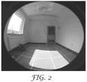
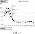
昼光方向転換フィルムを含む適切な構造体を使用することにより、通常は床に当たる太陽光を使用して自然照明を提供することができる。図2(LRFなし)と図3(LRFあり)との比較は、LRF201の使用により床から天井に方向転換することができる光量の一例を示す。 By using a suitable structure that includes a daylight diversion film, sunlight, which normally hits the floor, can be used to provide natural lighting. The comparison of FIG. 2 (without LRF) and FIG. 3 (with LRF) shows an example of the amount of light that can be turned from floor to ceiling by using LRF201.
建物(居住用及び商業用)は総消費エネルギーの約40%を占め、照明はそのエネルギーの約30%に相当する。人工照明のほんの一部でも自然光で代用することにより大幅なエネルギー節約をもたらすことができる。北米照明学会(IES、The Illuminating Engineering Society of North America)は、昼光照明システムの有効性を特徴付ける、spatial Daylight Autonomy即ちsDAと称する総合的な昼光照度測定基準を開発した。米国における国防総省のいくつかの拠点で行われた広範囲な研究は、3MのDRFの設置によりsDA値が向上することを示した。エネルギー節約に加え、昼光照明は、作業者の生産性の向上、成績の上昇、並びに気分及びエネルギーの向上に関してソフトな利点を有する。 Buildings (residential and commercial) account for about 40% of total energy consumption, and lighting accounts for about 30% of that energy. Substituting natural light for even a small portion of artificial lighting can result in significant energy savings. The Illuminating Engineering Society of North America (IES) has developed a comprehensive daylight illuminance measure called sDA, which characterizes the effectiveness of daylight lighting systems. Extensive studies conducted at several Pentagon centers in the United States have shown that the installation of 3M DRF improves sDA values. In addition to saving energy, daylight lighting has soft advantages in terms of improving worker productivity, improving performance, and improving mood and energy.
自然昼光を使用してある領域が照明されている場合に頻繁に遭遇する問題は、光をどのように適切かつ均一に行き渡らせるかである。例えば、建物内においてある領域が照明されている場合、通常、その領域の一部は他に比べてあまり光が当たらず、またある場所では建物の使用者が光源からのグレアに悩まされる。この問題に対処する1つの解決策は、拡散体の使用である。 A frequently encountered problem when an area is illuminated using natural daylight is how to distribute the light properly and evenly. For example, when an area of a building is illuminated, part of that area is usually less exposed to light than others, and in some places the building user suffers from glare from the light source. One solution to address this problem is the use of diffusers.
概して、微細構造化光方向転換フィルムは、微細構造化フィーチャが機械的損傷及び/又は化学的損傷(例えば、窓洗浄剤)を受けることがあるという理由で、特定の状況下において破損しやすい場合がある。LRFの微細構造化要素を保護しようとする場合における課題の1つは、カバー又は保護層を付加するための積層プロセスがこれら微細構造化要素の損傷の原因となる可能性があることである。拡散体などの任意の他の種類の機能性層又はフィルムをLRFの微細構造化要素の側に積層しようとする際にも同じ課題が生じる。加えて、LRFに隣接する更なる層の存在もまたその光学的性質を変更する可能性があるとともに、その光方向転換性質を大幅に低下させる又は変更する可能性がある。本開示の目的の1つは、LRFなどの微細構造化フィルムを、微細構造化フィルムの光学性能を大きく犠牲にすることなく、別の機能性フィルムに結合することを可能にするフィルム構造体を提供することである。 In general, microstructured light redirect films are vulnerable to breakage under certain circumstances because the microstructured features can be mechanically and / or chemically damaged (eg, window cleaners). There is. One of the challenges in trying to protect the microstructured elements of the LRF is that the laminating process for adding a cover or protective layer can cause damage to these microstructured elements. The same problem arises when attempting to laminate any other type of functional layer or film, such as a diffuser, on the side of the microstructured element of the LRF. In addition, the presence of additional layers adjacent to the LRF can also alter its optical properties and can significantly reduce or alter its optical turning properties. One of the objects of the present disclosure is to provide a film structure that allows a microstructured film such as LRF to be bonded to another functional film without significantly sacrificing the optical performance of the microstructured film. To provide.
本開示は、特に、他のフィルムに結合された光方向転換フィルムなどの微細構造化光学フィルムを含むフィルム構造に関する。 The present disclosure relates, in particular, to film structures including microstructured optical films such as optical redirect films coupled to other films.
一部の実施形態では、本開示のフィルム構造体は、2つのフィルム、即ち、a)第1主面と第1主面とは反対側の第2主面とを有する第1の光学フィルムであって、第1主面は、複数の微細構造化プリズム要素の秩序配列を含む微細構造化表面を含む、第1の光学フィルムと、b)第1主面と第1主面とは反対側の第2主面とを有するカバーフィルムであって、第2主面は、第1の光学フィルムの第1主要構造化表面(first major structured surface)の微細構造化プリズム要素の1つ以上に隣接して配置されており、接触しており、結合されている、カバーフィルムと、を含む、光管理フィルム構造体を含む。微細構造化プリズム要素の断面は、同一微細構造体内に2つ以上のピークを含む。 In some embodiments, the film structure of the present disclosure is a first optical film having two films, i.e., a) a first main surface and a second main surface opposite the first main surface. The first main surface is a first optical film containing a finely structured surface containing an ordered arrangement of a plurality of finely structured prism elements, and b) the first main surface and the opposite side of the first main surface. A cover film having a second main surface of the above, wherein the second main surface is adjacent to one or more of the finely structured prism elements of the first major structured surface of the first optical film. Includes an optical control film structure, including a cover film, which is arranged, in contact with, and bonded to. The cross section of the microstructured prism element contains two or more peaks within the same microstructure.
第1の光学フィルムの第1主面とカバーフィルムの第2主面は、接着剤層と第1の光学フィルムの第1主面上の微細構造化プリズム要素とによって部分的に占められる密閉体積を画定する。この体積は1つ以上の光学活性領域を画定し、1つ以上の光学活性領域では、空気又は任意の他の合成代替物(例えばエアロゲル)などの微細構造化プリズム要素に直接隣接する第1の材料は、微細構造化プリズム要素による光の方向転換を可能にする屈折率差(微細構造化プリズム要素に比べて低い)を有する。第1の材料(例えば空気)と微細構造化プリズム要素との間の屈折率差により、入射光の方向転換を可能にする。これら1つ以上の光学活性領域は、微細構造化プリズム要素の一部分に隣接している第2の材料、典型的には接着剤によって境界付けられている。接着剤の屈折率が微細構造化プリズム要素の屈折率と類似している場合、微細構造化プリズム要素に直接隣接している接着剤の存在により、微細構造化プリズム要素の、接着剤と接触している部分の屈折率が低下する。 The first main surface of the first optical film and the second main surface of the cover film are sealed volumes partially occupied by the adhesive layer and the microstructured prism elements on the first main surface of the first optical film. Is defined. This volume defines one or more optically active regions, in which in one or more optically active regions a first, directly adjacent to a microstructured prism element such as air or any other synthetic alternative (eg, airgel). The material has a refractive index difference (lower than the microstructured prism element) that allows the light to be redirected by the microstructured prism element. The difference in index of refraction between the first material (eg air) and the microstructured prism element allows for diversion of incident light. These one or more optically active regions are bounded by a second material, typically an adhesive, adjacent to a portion of the microstructured prism element. If the index of refraction of the adhesive is similar to the index of refraction of the microstructured prism element, the presence of the adhesive directly adjacent to the microstructured prism element causes contact with the adhesive of the microstructured prism element. The refractive index of the part is reduced.
第1の光学フィルム上の微細構造化プリズム要素のある部分(例えば、ピークのうちの1つ以上の先端)が接着剤層に貫入している場合、第1の光学フィルムとカバーフィルムは接着剤層によって結合されている。先端(例えばピーク)が、完全に貫入するのではなく、部分的に貫入することによって、光を屈折させるための微細構造化プリズム要素の低屈折率の界面(例えば、空気又は低屈折率の合成材料)が存在することができるようになる。 If some portion of the microstructured prism element on the first optical film (eg, the tip of one or more of the peaks) penetrates the adhesive layer, the first optical film and cover film are adhesive. It is connected by layers. A low index interface (eg, air or low index synthesis) of a microstructured prism element for refracting light by partially penetrating rather than completely penetrating the tip (eg peak). Material) will be able to exist.
一部の実施形態では、接着剤は粒子又はビーズなどの複数の拡散剤を含む。粒子は、光を散乱(拡散)させるための、例えば、シリカ、アルミナ、TiO2、又はジルコニアのマイクロ粒子若しくはナノ粒子を含み得る。代替的な実施形態としては、接着剤に球状ビーズを添加することができる。ビーズの屈折率が接着剤の屈折率に一致する場合、ビーズは透明であっても、ヘイズを発生させ、透明度を低下させるおそれのある粗面を生じさせる可能性がある。例えば、PMMAのビーズを、類似の屈折率を持つアクリレート系接着剤に添加することができる。一部の実施形態では、粒子は、0.1~100マイクロメートル、又は0.5~50マイクロメートル、又は0.7~20マイクロメートルの範囲内の平均直径を有する。例示的実施形態では、周囲条件下で24時間後などしばらく経過した後に粒子が凝集しない安定な分散体を粒子が提供するように、粒子は「表面改質」することができる。In some embodiments, the adhesive comprises a plurality of diffusing agents such as particles or beads. The particles may include, for example, silica, alumina, TiO2 or zirconia microparticles or nanoparticles for scattering (diffusing) light. As an alternative embodiment, spherical beads can be added to the adhesive. If the index of refraction of the beads matches the index of refraction of the adhesive, even if the beads are transparent, they can cause haze and create rough surfaces that can reduce transparency. For example, PMMA beads can be added to an acrylate-based adhesive with a similar index of refraction. In some embodiments, the particles have an average diameter in the range of 0.1-100 micrometers, or 0.5-50 micrometers, or 0.7-20 micrometers. In an exemplary embodiment, the particles can be "surface modified" so that the particles provide a stable dispersion in which the particles do not aggregate after some time, such as after 24 hours under ambient conditions.
一実施形態では、本開示は、
・第1主面と第1主面とは反対側の第2主面とを有する光方向転換フィルムであって、
光方向転換フィルムの第1主面は複数の微細構造化プリズム要素を含み、
微細構造化プリズム要素の1つ以上は第1ピーク及び第2ピークを有し、
第1ピークは高さH1を有し、第2ピークは高さH2を有し、
H3は、H1-H2であり、H3は、1マイクロメートル以上である、
光方向転換フィルムと、
・接着剤を含む接着剤層であって、第1主面と第1主面とは反対側の第2主面とを有する接着剤層と、
・第1主面と第1主面とは反対側の第2主面とを有するカバーフィルムと、
を含み、
微細構造化プリズム要素のうちの1つ以上の第1ピークは、接着剤層の第1主面に少なくとも一部貫入しており、
接着剤層の第2主面は、カバーフィルムの第1主面に隣接している、
フィルム構造体に関する。In one embodiment, the present disclosure is:
An optical direction-changing film having a first main surface and a second main surface opposite to the first main surface.
The first main surface of the light turning film contains multiple microstructured prism elements.
One or more of the microstructured prism elements has a first peak and a second peak.
The first peak has a height H1 and the second peak has a height H2.
H3 is H1-H2 and H3 is 1 micrometer or more.
Light direction change film and
An adhesive layer containing an adhesive and having a first main surface and a second main surface opposite to the first main surface.
A cover film having a first main surface and a second main surface opposite to the first main surface,
Including
One or more first peaks of the microstructured prism elements penetrate at least partly into the first main surface of the adhesive layer.
The second main surface of the adhesive layer is adjacent to the first main surface of the cover film.
Regarding film structures.
他の実施形態では、フィルム構造体は、
・第1主面と第1主面とは反対側の第2主面とを有する光方向転換フィルムであって、
光方向転換フィルムの第1主面は複数の微細構造化プリズム要素を含み、
微細構造化プリズム要素の1つ以上は第1ピーク及び第2ピークを有し、
第1ピークは高さH1を有し、第2ピークは高さH2を有し、
H3は、H1-H2であり、H3は、1マイクロメートル~8マイクロメートルである、
光方向転換フィルムと、
・接着剤を含む接着剤層であって、第1主面と第1主面とは反対側の第2主面とを有する接着剤層と、
・第1主面と第1主面とは反対側の第2主面とを有するカバーフィルムと、
を含み、
・拡散層と、を含み、
フィルム構造体が垂直位にあるとき、微細構造化プリズム要素の第1ピークは、第2ピークより上に位置的に配置されており、
第1ピークは頂角B1を有し、第2ピークは頂角B2を有し、B1<B2であり、
微細構造化プリズム要素のうちの1つ以上の第1ピークは、接着剤層の第1主面に少なくとも一部貫入しており、
光方向転換フィルムの第1主面は、接着剤層の第1主面に結合されており、
接着剤層の第2主面は、カバーフィルムの第1主面に結合されている。In other embodiments, the film structure is
An optical direction-changing film having a first main surface and a second main surface opposite to the first main surface.
The first main surface of the light turning film contains multiple microstructured prism elements.
One or more of the microstructured prism elements has a first peak and a second peak.
The first peak has a height H1 and the second peak has a height H2.
H3 is H1-H2 and H3 is 1 to 8 micrometers.
Light direction change film and
An adhesive layer containing an adhesive and having a first main surface and a second main surface opposite to the first main surface.
A cover film having a first main surface and a second main surface opposite to the first main surface,
Including
・ Including the diffusion layer
When the film structure is in the vertical position, the first peak of the microstructured prism element is positioned above the second peak.
The first peak has an apex angle B1, the second peak has an apex angle B2, and B1 <B2.
One or more first peaks of the microstructured prism elements penetrate at least partly into the first main surface of the adhesive layer.
The first main surface of the light turning film is bonded to the first main surface of the adhesive layer.
The second main surface of the adhesive layer is bonded to the first main surface of the cover film.
他の実施形態では、本開示は、上述のようなフィルム構造体を含む窓フィルムに関する。更に別の実施形態では、本開示は本明細書に記載のフィルム構造体を含む窓に関する。 In another embodiment, the present disclosure relates to a window film comprising a film structure as described above. In yet another embodiment, the present disclosure relates to a window comprising the film structure described herein.
本発明で使用する全ての科学用語及び専門用語は、特に指示がない限り、当該技術分野において一般的に使用される意味を有する。本明細書に提示される定義は、本出願で頻繁に用いられる特定の用語の理解を促すためのものであり、そうした用語の妥当な解釈を本開示の文脈で排除することを意図していない。 All scientific and technical terms used in the present invention have meanings commonly used in the art unless otherwise indicated. The definitions presented herein are intended to facilitate understanding of certain terms frequently used in this application and are not intended to exclude reasonable interpretation of such terms in the context of the present disclosure. ..
特に示さない限り、本明細書及び特許請求の範囲に用いられる加工寸法(特徴サイズ)、量及び物理的特性を表す、説明及び特許請求の範囲における数字は全て、全ての場合において、「約」という用語によって修飾されているものとして理解されるべきである。したがって、特に記載のない限り、前述の明細書及び添付の請求の範囲に記載されている数のパラメータは、本明細書で開示する教示を利用する当業者が得ようと試みる所望の特性に応じて変動し得る近似値である。最低限でも、また特許請求の範囲への均等論の適用を制限する試みとしてでもなく、各数値パラメータは、少なくとも、報告される有効桁の数を踏まえて、通常の四捨五入法を適用することによって、解釈されるべきである。本発明の広い範囲を記載するために使用される数値範囲及びパラメータは近似値であるが、具体例の数値は、可能な限り正確に報告される。しかしながら、どの数値も、それぞれの試験測定値に見られる標準偏差から必然的に生じる一定の誤差を本質的に含んでいる。 Unless otherwise stated, all figures in the description and claims that represent the processing dimensions (feature size), quantities and physical properties used in this specification and the claims are "about" in all cases. It should be understood as being modified by the term. Accordingly, unless otherwise stated, the number of parameters described in the specification and the appended claims depends on the desired characteristics to be obtained by those skilled in the art utilizing the teachings disclosed herein. It is an approximate value that can fluctuate. At a minimum, and not in an attempt to limit the application of the doctrine of equivalents to the claims, each numerical parameter is at least by applying the usual rounding method, given the number of valid digits reported. , Should be interpreted. Numerical ranges and parameters used to describe the broad range of the invention are approximate values, but the numerical values of the specific examples are reported as accurately as possible. However, each number essentially contains a certain error that inevitably arises from the standard deviation found in each test measurement.
端点による数値範囲の列挙には、その範囲内に包含される全ての数値(例えば、1~5の範囲は、例えば、1、1.5、2、2.75、3、3.80、4及び5を含む)、及びその範囲内の任意の範囲が含まれる。 In the enumeration of the numerical range by the end points, all the numerical values included in the range (for example, the range of 1 to 5 is, for example, 1, 1.5, 2, 2.75, 3, 3.80, 4). And 5), and any range within that range is included.
本明細書及び添付の特許請求の範囲において使用する場合、単数形「a」、「an」、及び「the」は、その内容について別段の明確な指示がない限り、複数の指示対象を有する実施形態を包含する。本明細書及び添付の特許請求の範囲において使用する場合、「又は」という用語は、その内容に別段の明確な指示がない限り、一般に、「及び/又は」を含む意味で用いられる。 As used herein and in the appended claims, the singular forms "a," "an," and "the" have multiple referents unless otherwise stated. Includes morphology. As used herein and in the appended claims, the term "or" is generally used to include "and / or" unless otherwise stated in its content.
用語「接着剤」とは、本明細書で使用する場合、2つの構成成分(被接着体)を一緒に接着するのに有用なポリマー組成物を指す。 The term "adhesive" as used herein refers to a polymer composition useful for adhering two components (adhesives) together.
本明細書で使用される場合、用語「結合される」とは、別の要素に対して粘着的に取り付けられた要素を指す。あらゆる種類の接着剤を用いて要素を互いに結合することができる。用語「結合される」は、接着剤若しくは接着剤層又は接着剤若しくは接着剤層に粘着的に取り付けられた別の要素への1つの要素(例えば、層又は個々の微細構造化プリズム要素)の粘着的な取り付けを表すために用いることができる。例えば、図11に示すように、微細構造化プリズム要素(一般的には、微細構造化プリズム要素を含むフィルム)は(各ピークの先端を介して)接着剤層に結合されているが、微細構造化プリズム要素(又はフィルム)は基材(例えばカバーフィルム)に結合されているとも言える。 As used herein, the term "combined" refers to an element that is adhesively attached to another element. Elements can be bonded to each other using any kind of adhesive. The term "bonded" refers to one element (eg, a layer or individual microstructured prism element) to an adhesive or adhesive layer or another element adhesively attached to the adhesive or adhesive layer. It can be used to represent an adhesive attachment. For example, as shown in FIG. 11, the finely structured prism element (generally, the film containing the finely structured prism element) is bonded to the adhesive layer (via the tip of each peak), but is fine. It can also be said that the structured prism element (or film) is bonded to a substrate (for example, a cover film).
接着剤層に貫入している微細構造化プリズム要素の部分の文脈において本明細書で使用する用語「貫入する」又は「貫入している」とは、接着剤がキュア、固化、硬化等されると、微細構造化プリズム要素(又は微細構造化プリズム要素を含むフィルム)を接着剤層又は別のフィルム又は基材(例えばカバーフィルム)に結合させる、接着剤層に埋め込まれている微細構造化プリズム要素の部分を指す。例えば、図12及び図13は、微細構造化プリズム要素の各ピークの先端が接着剤層に貫入していることを示す。接着剤後(adhesive later)に貫入している微細構造化プリズム要素の部分は、微細構造化プリズム要素の「結合部」と定義される。図14A及び図14Bは、微細構造化プリズム要素(又は光方向転換フィルム)が接着剤層に貫入した微細構造化プリズム要素のピークの先端によって接着剤層(又は接着剤層に結合されている基材)に結合され、プリズム要素と接着剤との間の表面接触が生じていることを示す。 As used herein, the term "penetrating" or "penetrating" in the context of the portion of the microstructured prism element that penetrates the adhesive layer means that the adhesive is cured, solidified, cured, etc. And a microstructured prism embedded in the adhesive layer that binds the microstructured prism element (or film containing the microstructured prism element) to the adhesive layer or another film or substrate (eg, cover film). Refers to the part of the element. For example, FIGS. 12 and 13 show that the tips of each peak of the microstructured prism element penetrate the adhesive layer. The portion of the microstructured prism element that penetrates after the adhesive is defined as the "joint" of the microstructured prism element. 14A and 14B show a group in which the microstructured prism element (or optical direction changing film) is bonded to the adhesive layer (or the adhesive layer) by the tip of the peak of the microstructured prism element penetrating into the adhesive layer. It is shown that surface contact has occurred between the prism element and the adhesive, which is bonded to the material).
本明細書で使用する用語「窓フィルム接着剤層」とは、例えば感圧性接着剤などの、窓又はグレイジングにフィルムを結合するのに好適な接着剤を含む層を指す。 As used herein, the term "window film adhesive layer" refers to a layer containing an adhesive suitable for binding a film to a window or glazing, such as a pressure sensitive adhesive.
用語「隣接している」とは、本明細書で使用する場合、「隣接している」が出現する文脈により理解されるように、2つの要素の相対位置を意味し、2つの要素は、例えば、互いに近接しているフィルム構造体内の層であり、互いに接触していてもそうでなくてもよく、2つの要素を分離する1つ以上の層を有していてもよい。 The term "adjacent", as used herein, means the relative position of the two elements, as understood by the context in which "adjacent" appears. For example, layers in a film structure that are in close proximity to each other and may or may not be in contact with each other and may have one or more layers that separate the two elements.
用語「直接隣接している」とは、本明細書で使用する場合、「直接隣接している」が出現する文脈により理解されるように、2つの要素の相対位置を意味し、2つの要素は、例えば、2つの要素を分離する任意の他の層を有することなく物理的に接触し、互いに直接隣り合うフィルム構造体内の層である。しかしながら、用語「直接隣接する」は、1つ又は両方の要素がプライマーで処理されている、又は例えば、エッチング、エンボス加工等、又は接着を向上させることができるコロナ処理若しくはプラズマ処理等などの表面処理によって、1つ又は両方の要素の表面がその性質に影響を及ぼすように改質されている状況を含む。 The term "directly adjacent", as used herein, means the relative position of two elements, as understood by the context in which "directly adjacent" appears. Is, for example, a layer in a film structure that is in physical contact without having any other layer separating the two elements and is directly adjacent to each other. However, the term "directly adjacent" refers to a surface where one or both elements are primed, or, for example, etching, embossing, etc., or corona treatment, plasma treatment, etc., which can improve adhesion. Includes situations where the treatment modifies the surface of one or both elements to affect their properties.
用語「構造体」又は「アセンブリ」は、本出願では、異なる層が共押出され得る、積層され得る、重ねて被覆され得る又はこれらの任意の組み合わせの多層フィルムに言及する場合、区別なく使用される。 The terms "structure" or "assembly" are used interchangeably in this application when referring to multilayer films in which different layers can be coextruded, laminated, overcoated or any combination thereof. To.
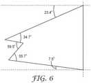
微細構造化プリズム要素に関連する用語「ピッチ」、「高さ」、「谷の角度」、「第1の挟角α」、「第2の挟角β」、「頂角」及び「アスペクト比」は、図5を参照して以下のように定義される。ピッチは辺Aの長さである。高さは、図5では辺Dと辺Eとによって形成されたピークである最も高いピーク(H1)の高さである。すなわち、微細構造体の高さは、Y軸から、図5では辺Dと辺Eとによって形成された最も高いピークの頂点までの水平距離である。谷の角度は角407である。第1の挟角すなわち角αは、角「a」である。第2の挟角すなわち角βは、角「b」である。頂角は、ピークの内角である。図5では、辺Bと辺Cとによって形成されたピークの頂角は角「d」であり、辺Dと辺Eとによって形成されたピークの頂角は角「c」である。アスペクト比は、微細構造化プリズム要素の高さとピッチとの間の比(H1/A)である。 Terms related to microstructured prism elements "pitch", "height", "valley angle", "first angle α", "second angle β", "top angle" and "aspect ratio" Is defined as follows with reference to FIG. The pitch is the length of the side A. The height is the height of the highest peak (H1), which is the peak formed by the side D and the side E in FIG. That is, the height of the microstructure is the horizontal distance from the Y-axis to the apex of the highest peak formed by the sides D and E in FIG. The angle of the valley is the
本明細書で使用する用語「光学フィルム」とは、少なくとも光学的に透明であり、高い可視光透過率を有する可能性があり、光学的にクリア又は透光性(transluscent)である可能性があり、付加的な光学効果も生じる可能性のあるフィルムを指す。付加的な光学効果の例としては、例えば、光の拡散、光の偏光、又はある波長の光の反射が挙げられる。光学フィルムは、スペクトルの可視光領域において、高い光学透明性を有する任意の好適なフィルムであってもよい。光学フィルムは、20%より大きい、50%より大きい、又はある好適な実施形態では、80%より大きい可視光透過率を有してもよい。光学フィルムは、単一層フィルム又は多層フィルム構造体であってもよい。 As used herein, the term "optical film" is at least optically transparent, may have high visible light transmittance, and may be optically clear or transluscent. Refers to a film that has and may also produce additional optical effects. Examples of additional optical effects include, for example, diffusion of light, polarization of light, or reflection of light of a certain wavelength. The optical film may be any suitable film having high optical transparency in the visible light region of the spectrum. The optical film may have a visible light transmittance greater than 20%, greater than 50%, or, in certain preferred embodiments, greater than 80%. The optical film may be a single-layer film or a multilayer film structure.
本明細書において使用される、用語「秩序配列」とは、複数の構造を指し、構造の規則的、反復的パターンを指す。 As used herein, the term "ordered sequence" refers to multiple structures and refers to regular, iterative patterns of structure.
本明細書において使用される、微細構造化プリズム要素の辺の文脈における用語「実質的に直線」とは、ほぼ直線であるが、製造プロセスにより導入される誤差により直線から逸脱し得る、又は方向転換された(屈折)光を拡散させるために意図的に小さな曲率(すなわち大きな半径)を有し得る辺を指す。 As used herein, the term "substantially straight" in the context of the edges of a microstructured prism element is approximately straight, but may deviate from or direct due to errors introduced by the manufacturing process. Refers to an edge that can intentionally have a small curvature (ie, a large radius) to diffuse the converted (refracted) light.
本明細書において使用される用語「光方向転換層」とは、微細構造化プリズム要素を含む層を指す。 As used herein, the term "light-turning layer" refers to a layer containing microstructured prism elements.
本明細書において使用される用語「光方向転換フィルム」又は「光誘導フィルム」とは、1つ以上の光方向転換層と、任意に、基材又は他の機能層などの他の付加的な層とを含むフィルムを指す。昼光方向転換フィルムは、光方向転換フィルムの一例である。 As used herein, the term "light-turning film" or "light-inducing film" refers to one or more light-turning layers and optionally other additional layers such as substrates or other functional layers. Refers to a film containing layers. The daylight turning film is an example of a light turning film.
光の方向転換は、一般に、光源が太陽である場合には、昼光方向転換、日光方向転換、又は太陽光方向転換と呼ばれ得る。 Light diversion can generally be referred to as daylight diversion, sunlight diversion, or solar diversion when the light source is the sun.
用語「フィルム」とは、本明細書で使用する場合、状況に応じて、単一層物品、又は種々の層が積層されてもよく、共押出されてもよく、コーティングされてもよく、若しくはこれらの任意の組み合わせであってもよい多層構造体のいずれかを意味する。 As used herein, the term "film" may be a single-layer article, or various layers may be laminated, co-extruded, coated, or these, depending on the circumstances. Means any of the multilayer structures which may be any combination of.
本明細書で使用される、短縮形で「微細構造体」と呼ばれることのある用語「微細構造化プリズム要素」とは、フィーチャの少なくとも2つの寸法が微視的であり、特定の角度特性を持つ入力光を特定の角度特性を持つ出力光に方向転換する加工された光学素子を指す。ある実施形態では、微細構造化プリズム要素の高さは1000マイクロメートル未満である。本開示の微細構造化プリズム要素は、ダブルピーク構造、1つ以上の曲線ファセットを含む構造、又はこれらの組み合わせなどのマルチピーク構造を含んでもよい。微細構造化プリズム要素はその全ての物理的及び光学的特性(例えば、グレア、TIR角等)を含め、国際公開第2016/064667号として公開されている「Room-Facing Light Redirecting Film with Reduced Glare」と題されるPCT出願、及び国際公開第2016/064621号として公開されている「Sun-Facing Light Redirecting Film with Reduced Glare」と題されるPCT出願に開示されおり、これらは参照により本明細書に組み込まれる。微細構造化プリズム要素410の例を図4~図9に示す。 As used herein, the term "microstructured prism element", sometimes abbreviated as "microstructure", means that at least two dimensions of a feature are microscopic and have specific angular characteristics. It refers to a processed optical element that converts the input light it has into output light with specific angular characteristics. In one embodiment, the height of the microstructured prism element is less than 1000 micrometers. The microstructured prism elements of the present disclosure may include a double-peak structure, a structure containing one or more curved facets, or a multi-peak structure such as a combination thereof. The microstructured prism element, including all its physical and optical properties (eg, glare, TIR angle, etc.), is published as International Publication No. 2016/0646667 "Room-Facing Light Redirecting Film with Reduced Glare". It is disclosed in the PCT application entitled "Sun-Facing Light Redirecting Film with Reduced Glare" published as International Publication No. 2016/066421 and these are disclosed herein by reference. Be incorporated. Examples of the finely structured
本明細書で使用される用語「拡散剤」とは、例えばマイクロビーズ又はナノ粒子などの、同一物品を通過する光の角拡散を増大させる、物品に組み込まれたフィーチャ又は添加物を指す。 As used herein, the term "diffusing agent" refers to a feature or additive incorporated into an article that increases the angular diffusion of light passing through the same article, such as microbeads or nanoparticles.
本開示では、用語「拡散層」、「拡散要素」又は「拡散体」は入れ替え可能であり、本明細書で使用する場合、可視光の拡散をもたらすフィルム構造体内の要素を指す。拡散要素は、可視光に関して拡散特性を有する層若しくはコーティング、又は処理される表面に拡散特性を与える本開示のフィルム構造体の層上の表面処理であってもよい。 In the present disclosure, the terms "diffusing layer", "diffusing element" or "diffusing body" are interchangeable and, as used herein, refer to an element within the film structure that results in the diffusion of visible light. The diffusing element may be a layer or coating having diffusive properties with respect to visible light, or a surface treatment on a layer of the film structure of the present disclosure that imparts diffusive properties to the surface to be treated.
本明細書で使用される、用語「より上に位置的に配置される」とは、微細構造化プリズム要素の1つのピークの、同一微細構造化プリズム要素の別のピークに対する相対位置を指す。微細構造化プリズム要素が垂直位(例えば、図4又は図5の微細構造化プリズム要素410を参照)にあり、その底辺(辺A)が垂直軸線(例えばy軸)に平行な場合、頂点がx軸からy方向の最長距離に位置するピークは、他のピークより上に位置的に配置されたピークである。この場合、x軸とy軸の位置は、微細構造化プリズム要素の全体が、xとyが両方とも正の値を有する象限内にあるように選択される。例えば、図4では、辺Cと辺D(頂角「d」)によって画定されるピークは、辺Dと辺E(頂角「c」)によって画定されるピークより上に位置的に配置されている。図7では、頂角が41.0°のピークは頂角61.3°のピークよりも上に位置的に位置されている。 As used herein, the term "positioned above" refers to the relative position of one peak of a microstructured prism element to another peak of the same microstructured prism element. If the microstructured prism element is in a vertical position (see, eg,
本明細書で使用する場合、RI1がRI2の±5%以内であれば、材料1の屈折率(「RI1」)は材料2の屈折率(「RI2」)に一致しているとされる。 As used herein, the index of refraction of material 1 (“RI1”) is considered to match the index of refraction of material 2 (“RI2”) if RI1 is within ± 5% of RI2.
以下の「部屋に面する」及び「太陽に面する」という定義では、光方向転換層が第1主面と第1主面とは反対側の第2主面とを有し、光方向転換フィルムの第1主面が微細構造化プリズム要素を含むと想定される。 In the following definitions of "facing the room" and "facing the sun", the light diversion layer has a first main surface and a second main surface opposite to the first main surface, and the light diversion. It is assumed that the first main surface of the film contains a microstructured prism element.
本明細書で使用する場合、光方向転換フィルム又は光方向転換フィルムを含む構造体の文脈において用語「部屋に面する」とは、入射光線が微細構造化プリズム要素を含む主面を通過する前に微細構造化プリズム要素を含まない光方向転換フィルムの主面を通過するフィルム又は構造体を指す。最も典型的な構成では、光方向転換フィルムが外装窓上に位置している場合(すなわち、窓が建物の外に面している場合)、「部屋に面する」構成の微細構造化プリズム要素は室内に面して方向付けられている。しかし、本明細書で定義される用語「部屋に面する」は、光方向転換フィルムが、建物の外に面してはいないが2つの内部領域の間にあるグレイジング又は他の種類の基材上にある構成も意味し得る。 As used herein, the term "facing the room" in the context of a light-altering film or a structure comprising a light-changing film is used before the incident light beam passes through a main surface containing a microstructured prism element. Refers to a film or structure that passes through the main surface of an optical direction change film that does not contain a microstructured prism element. In the most typical configuration, a microstructured prism element in a "room-facing" configuration when the light-turning film is located on the exterior window (ie, the window faces the outside of the building). Is oriented facing the room. However, the term "room facing" as defined herein is a glazing or other type of basis in which the light diversion film is not facing the outside of the building but is between two internal areas. The composition on the material can also mean.
本明細書で使用する場合、光方向転換フィルム又は光方向転換フィルムを含む構造体の文脈において用語「太陽に面する」とは、入射光線が他の主面(微細構造化プリズム要素を含まない主面)を通過する前に微細構造化プリズム要素を含む光方向転換フィルムの主面を通過するフィルム又は構造体を指す。最も典型的な構成では、光方向転換フィルムが外装窓上に位置している場合(すなわち、窓が建物の外に面している場合)、「太陽に面する」構成の微細構造化プリズム要素は太陽に面して方向付けられている。しかし、本明細書で定義される用語「太陽に面する」は、光方向転換フィルムが、建物の外に面してはいないが2つの内部領域の間にあるグレイジング上にある構成も意味し得る。 As used herein, the term "facing the sun" in the context of a light-changing film or a structure comprising a light-turning film means that the incident light does not include other main surfaces (microstructured prism elements). Refers to a film or structure that passes through the main surface of an optical redirection film containing a microstructured prism element before passing through the main surface). In the most typical configuration, a microstructured prism element in a "sun-facing" configuration when the light-turning film is located on the exterior window (ie, the window faces the outside of the building). Is oriented facing the sun. However, the term "facing the sun" as defined herein also means a configuration in which the light diversion film is on glazing between two internal regions that do not face the outside of the building. Can be.
本明細書で使用する場合、本開示の物品の縁端について述べる場合の用語「封止」又は「封止された」は、水分、空気及び/又は他の汚染物質など特定の望ましくない要素の侵入を阻止することを意味する。 As used herein, the term "sealed" or "sealed" as used to describe the edges of the articles of the present disclosure refers to certain unwanted elements such as moisture, air and / or other contaminants. It means to stop the invasion.
本明細書で使用する用語「固化」又は「硬化」とは、物理的手段(例えば、温度(加熱又は冷却のいずれか))、化学的手段、放射手段(例えば紫外線またはeビーム放射)を用いて材料を初期状態から、流動性、剛性等など異なる性質を有するその所望の最終状態に転換することを指す。 As used herein, the term "solidification" or "curing" uses physical means (eg, temperature (either heating or cooling)), chemical means, radiating means (eg, ultraviolet or e-beam radiation). It refers to converting a material from an initial state to its desired final state having different properties such as fluidity and rigidity.
用語「可視光」は、本明細書で使用する場合、本開示では380nm~700nmであると解釈される可視スペクトル内の放射を意味する。 The term "visible light" as used herein means radiation within the visible spectrum, which is interpreted herein to be 380 nm to 700 nm.
本明細書で使用される用語「パンチスルー」とは、光誘導フィルム構造体を方向転換なく直接透過(又は正透過)する光を指す。パンチスルーの別の実施形態は、正透過から+5度又は-5度にのみ方向転換する光である。パンチスルー、特に、浅く、光がLRFに入射する水平位置から下に導かれる光においては、グレアを引き起こす可能性がある。 As used herein, the term "punch-through" refers to light that is directly transmitted (or positively transmitted) through a light-guided film structure without turning. Another embodiment of punch-through is light that diverts only from positive transmission to +5 degrees or −5 degrees. Punch-through, especially in shallow light that is guided downward from a horizontal position where the light is incident on the LRF, can cause glare.

以下の説明では、本明細書に記載する添付の図面について述べる。ある場合において、図は、実例として、本開示のいくつかの特定の実施形態を示す場合がある。本開示の範囲又は趣旨から逸脱することなく、図に明示されるものと異なる他の実施形態も検討され、実施され得ることを理解されたい。したがって、以下の発明を実施するための形態は、限定的な意味で解釈されないものとする。 The following description describes the accompanying drawings described herein. In some cases, the figure may, by way of example, show some particular embodiments of the present disclosure. It should be understood that other embodiments different from those specified in the figure may be considered and implemented without departing from the scope or intent of this disclosure. Therefore, the embodiment for carrying out the following invention shall not be construed in a limited sense.
本発明の開示は、光又は昼光方向転換フィルム及び光又は昼光方向転換層を全体的な構造体の一部として述べることにより例示するが、本出願で教示され、請求される概念及び対象は、光方向転換フィルムではない他の微細構造化光学フィルムに及ぶことができる。 The disclosure of the present invention exemplifies by describing the light or daylight diversion film and the light or daylight diversion layer as part of the overall structure, but the concepts and objects taught and claimed in this application. Can extend to other microstructured optical films that are not optical redirection films.
概して、本開示は、2つのフィルムが互いに結合され、フィルムの少なくとも1つが微細構造化プリズム要素を含むフィルム構造体に関する。典型例では、微細構造化プリズム光学フィルムは光方向転換フィルムであってもよく、第2のフィルムはカバーフィルムである。カバーフィルムの対向する表面に対する光学フィルムの構造化表面の結合は、接着剤の層によって行われ、微細構造化光学フィルムの微細構造化プリズム要素の表面フィーチャの特定部分が接着剤に微細構造化プリズム要素の高さに満たない深さまで部分的に貫入する。本開示の微細構造化プリズム要素は2つ以上のピークを有する。一部の実施形態では、微細構造化プリズム要素の1つのピークのみが接着剤に部分的に貫入する。他の実施形態では、両ピーク(例えば、2つのピークを有する微細構造化プリズム要素の)が接着剤に貫入する。ある状況においては、光の方向転換を増大するために、複数ピーク微細構造化プリズム要素の1つのピークのみが接着剤に貫入することが好ましい。 In general, the present disclosure relates to a film structure in which two films are bonded together and at least one of the films contains a microstructured prism element. In a typical example, the microstructured prism optical film may be an optical direction changing film, and the second film is a cover film. Bonding of the structured surface of the optical film to the opposite surface of the cover film is done by a layer of adhesive, where specific portions of the surface features of the microstructured prism elements of the microstructured optical film are attached to the adhesive. Partially penetrates to a depth less than the height of the element. The microstructured prism elements of the present disclosure have two or more peaks. In some embodiments, only one peak of the microstructured prism element penetrates the adhesive partially. In another embodiment, both peaks (eg, of a microstructured prism element with two peaks) penetrate the adhesive. In some situations, it is preferred that only one peak of the multi-peak microstructured prism element penetrates the adhesive in order to increase the direction of light.
典型的には、接着剤層は、接着剤層と微細構造化プリズム要素を含む光方向転換層の部分との間に間隙が残るように、接着剤に貫入する関連の微細構造化プリズム要素の高さに満たない厚さを有する。 Typically, the adhesive layer is of the associated microstructured prism element that penetrates the adhesive so that a gap remains between the adhesive layer and the portion of the optical diversion layer that contains the microstructured prism element. It has a thickness less than the height.
接着剤に微細構造化プリズム要素が完全に貫入すると、微細構造化プリズム要素と周囲の低屈折率材料(例えば空気)との間に必要な屈折率差が低減又は排除され、光方向転換に大きな悪影響を及ぼす。 Complete penetration of the microstructured prism element into the adhesive reduces or eliminates the required index of refraction difference between the microstructured prism element and the surrounding low index material (eg, air), which is significant for light diversion. Adversely affect.
本出願で開示及び教示される2つのフィルム(例えば、光方向転換フィルム及びカバーフィルム)間の結合の種類は、フィルムの光方向転換機能(又は他の微細構造化光学フィルムの適切な機能)を増大するための、光方向転換フィルムの選択した領域(例えば、微細構造化プリズム要素のピークの先端など)のみによる結合を意味する。以下に示すように、微細構造化プリズム要素に接する接着剤が存在することにより、微細構造化プリズム要素の結合部(例えばピークの部分)が接着剤に貫入する際の光方向転換機能が低下するため、結合部の大きさ及び数と、光方向転換フィルムとカバーフィルムとの間の結合強度との間には関数的なバランスが存在する。すなわち、結合部の大きさ及び数が増加するにつれて結合の強度が増大し、有益であるが、本来の光方向転換フィルムの光方向転換機能を実施するために残される領域は少なくなる。逆に、結合部の大きさが減少するにつれて方向転換される光の量は多くなるが、結合に利用可能な領域の大きさが減少し、2つのフィルム間の結合強度が減少する。 The type of bond between the two films disclosed and taught in this application (eg, optical diversion film and cover film) provides the optical diversion function of the film (or the appropriate function of other microstructured optical films). It means binding only by a selected region of the optical transforming film for augmentation (eg, the tip of the peak of a microstructured prism element). As shown below, the presence of the adhesive in contact with the microstructured prism element reduces the optical direction change function when the junction (eg, peak portion) of the microstructured prism element penetrates the adhesive. Therefore, there is a functional balance between the size and number of the bonding portions and the bonding strength between the optical direction changing film and the cover film. That is, as the size and number of the bonding portions increase, the strength of the bonding increases, which is beneficial, but the area left for carrying out the optical direction changing function of the original light direction changing film is reduced. Conversely, as the size of the bond decreases, the amount of light that is redirected increases, but the size of the region available for bonding decreases, and the bond strength between the two films decreases.
接着剤の屈折率とプリズム要素の屈折率が類似している場合、光は方向転換されず、フィルムをパンチスルーするため、グレアが発生する可能性がある。結合部の大きさ及び数が増加するにつれてパンチスルーの量は増加する。 If the index of refraction of the adhesive and the index of refraction of the prism element are similar, the light will not be redirected and will punch through the film, which can lead to glare. The amount of punch-through increases as the size and number of joints increases.
複数ピーク微細構造化プリズム要素
概して、昼光方向転換用途においては、入射光は、LRFに光が入射する水平位置から上方に、浅い角度で方向転換されることが好ましい。この配分では、内部空間内に深く、自然光が不足している窓から離れた場所に光を与える。Multi-Peak Microstructured Prism Element In general, for daylight diversion applications, it is preferred that the incident light be redirected upward from the horizontal position where the light is incident on the LRF at a shallow angle. This distribution provides light deep within the interior space, away from windows that lack natural light.
光誘導フィルムの出力光を図10に示す。一般に、光を室内の上方に、深く方向転換することが望まれる。方向転換されない光(パンチスルー)又は下方に誘導される光はグレアをもたらすため望ましくない。本発明者らは、性能を最適化する光方向転換をモデル化及び測定するための異なる上方領域及び下方領域を示している。例えば、図10に示すように「直接グレア」として示される領域は0度から水平より下の-15度の角度である。本発明者らは、方向転換性能の向上に加えて、実行可能な製造プロセスを使用して微細構造化プリズム要素を製造できるようにするために課される他の設計制約条件を考慮した。 The output light of the light induction film is shown in FIG. In general, it is desirable to divert the light deeper into the room. Non-turning light (punch-through) or downwardly guided light is undesirable as it causes glare. We show different upper and lower regions for modeling and measuring optical diversions that optimize performance. For example, as shown in FIG. 10, the region shown as "direct glare" is at an angle of -15 degrees below horizontal from 0 degrees. In addition to improving turnaround performance, we have considered other design constraints imposed to enable the manufacture of microstructured prism elements using feasible manufacturing processes.
2つのピークを有する微細構造化プリズム要素に関しては、各ピークは異なる挟角及び異なる高さを有してもよい。本発明者らは、改良された微細構造化プリズム要素を設計するために、結合プロセスを考慮した。例えば、本発明者らは、昼光方向転換フィルムとカバーフィルムの積層時、接着剤の流れる方向が先端沈み点(図11)によって制限されることを見出した。 For microstructured prism elements with two peaks, each peak may have different angles and different heights. We considered the coupling process to design an improved microstructured prism element. For example, the present inventors have found that the flow direction of the adhesive is limited by the tip sinking point (FIG. 11) when the daylight direction changing film and the cover film are laminated.
典型的には、接着剤は、ファセットが先端沈み点のどちらの側にあるかに応じて、ファセットに沿って流れる。2つのピークを有する微細構造化プリズム要素の4つのファセットに沿った接着剤の流れの方向は、図11の矢印によって示される。上述のように、ファセットに沿った接着剤の流れは、ファセット沿いの過度の接着剤、更に光学性能の劣化につながる。本発明者らは、接着剤の流れの大きさは、図12に示すように、特定のファセットによって変位する接着剤の体積に比例することを見出した。 Typically, the adhesive flows along the facet, depending on which side of the tip sink point the facet is on. The direction of adhesive flow along the four facets of the microstructured prism element with two peaks is indicated by the arrows in FIG. As mentioned above, the flow of adhesive along the facet leads to excessive adhesive along the facet and further deterioration of optical performance. We have found that the magnitude of the adhesive flow is proportional to the volume of the adhesive displaced by a particular facet, as shown in FIG.
本発明者らは、ファセットによって変位する接着剤の体積を、接着剤内に埋め込まれた領域の関数として算出した。図12に示される4つのファセットの埋め込まれた領域は、m=1.22、n=7.05、o=3.62、及びp=2.40である。これらの領域に基づくと、より緩やかなファセット(n及びo)が急なファセット(m及びp)よりも多くの接着剤を変位すると予想される。本発明者らは、このモデルに基づき、これらのファセットに沿った光学性能が急なファセットに沿った光学性能よりも良好でないと予想する。本発明者のモデルは、図14(a)及び図14(b)に示される構造を用いて検証されている。 We calculated the volume of adhesive displaced by the facet as a function of the area embedded in the adhesive. The embedded regions of the four facets shown in FIG. 12 are m = 1.22, n = 7.05, o = 3.62, and p = 2.40. Based on these regions, it is expected that looser facets (n and o) will displace more adhesive than steep facets (m and p). Based on this model, we anticipate that the optical performance along these facets will not be better than the optical performance along the steep facets. The inventor's model has been validated using the structures shown in FIGS. 14 (a) and 14 (b).
この例では、構造は、厚さ6μmの接着剤を有するフィルムに埋め込んだ。各ファセットに沿って認められる接着剤の流れの程度は、その傾斜角に直接関係する変位した接着剤の体積に比例する。図14(b)に示されるように、より緩やかな傾斜(2、3)は、急な傾斜(1、4)に比べて大幅に多いそのファセットに沿った接着剤の流れ(白い領域)を示す。図14(a)及び図14(b)では、微細構造化プリズム要素の周囲の暗い又は黒い領域は空気であり、微細構造化プリズム要素の周りに空気が存在することで、昼光方向転換フィルムの光屈折特性を補助する。図に見ることができるように、傾斜2及び傾斜3により画定された谷に多くの接着剤が蓄積されている。接着剤の厚さに応じて、この谷は、接着剤にほぼ完全に埋め込むことができるが、図15に示すように、パンチスルーグレアの増加を招くことになる。 In this example, the structure was embedded in a film with a 6 μm thick adhesive. The degree of adhesive flow observed along each facet is proportional to the volume of displaced adhesive that is directly related to its angle of inclination. As shown in FIG. 14 (b), the gentler slopes (2, 3) have significantly more adhesive flow (white areas) along the facet than the steep slopes (1, 4). show. In FIGS. 14 (a) and 14 (b), the dark or black region around the microstructured prism element is air, and the presence of air around the microstructured prism element results in a daylight diversion film. Assists in the light refraction characteristics of. As can be seen in the figure, a lot of adhesive is accumulated in the valley defined by the
図15に、構造内への接着剤の流れを、3~8μmの範囲の接着剤厚さの関数として示す。厚さ3μの接着剤を使用すると、構造は接着剤にほとんど埋め込まれない一方で、厚さ8μmの接着剤では、谷はほぼ完全に接着剤で満たされる。図15のコノスコーププロット及び図16に示すように、構造の沈みが増すと対応するパンチスルーの増加が認められる。 FIG. 15 shows the flow of adhesive into the structure as a function of adhesive thickness in the range of 3-8 μm. With a 3 μm thick adhesive, the structure is barely embedded in the adhesive, while with an 8 μm thick adhesive, the valleys are almost completely filled with the adhesive. As shown in the conoscope plot of FIG. 15 and FIG. 16, a corresponding increase in punch-through is observed with increasing structural subsidence.
しかし、先端の沈みを低減することでパンチスルーを減少することにより光学的特性(optics)が向上する一方、フィルムと積層体との間の剥離強度の低下という犠牲を払うことになる。剥離強度の低下はフィルムの耐久性に悪影響を及ぼす可能性がある。先端の沈みが剥離力に及ぼす影響を、図17に示す。この図に見られるように、接着剤の厚さが3μmから8μmに増加すると剥離は3倍を超えて増加する。 However, while reducing punch-through by reducing tip sinking improves optics, it comes at the expense of reduced peel strength between the film and the laminate. Decreased peel strength can adversely affect the durability of the film. The effect of the sinking of the tip on the peeling force is shown in FIG. As can be seen in this figure, as the thickness of the adhesive increases from 3 μm to 8 μm, the peeling increases more than three times.
本発明者のモデルによる結果及び実証的試験による観察に基づき、本発明者らは、非対称複数ピーク方向転換微細構造化プリズム要素を使用する場合の、先端の結合を伴う積層法に好適な微細構造化プリズム要素の設計及び配向に関する特定のガイドラインを決定した。
1.1つのピークのみを接着剤に沈めることが好ましい。
2.「急な」ピーク(より小さな頂角を有するピーク)を接着剤に沈めることが好ましい。Based on the results of our model and observations by empirical testing, we have found that microstructures suitable for laminating with tip coupling when using asymmetric multi-peak redirection microstructured prism elements. Specific guidelines for the design and orientation of the prism element have been determined.
1. It is preferable to submerge only one peak in the adhesive.
2. 2. It is preferable to submerge the "steep" peaks (peaks with smaller apex angles) in the adhesive.
これら概念を、図14の基本の微細構造化プリズム要素に灰色の陰影を付けて示す図18に示す。修正を加えた2つの構造を濃い陰影を付けて示す。
a.上部(より急な)ピークの方が5μm高い
b.下部(より緩やかな)ピークの方が5μm高いThese concepts are shown in FIG. 18, which shows the basic microstructured prism elements of FIG. 14 with gray shading. The two modified structures are shown with dark shading.
a. The upper (steeper) peak is 5 μm higher b. The lower (more gradual) peak is 5 μm higher
両場合において、構造は接着剤中に4μm沈むようにモデル化した。次いで、図35に示すように、様々な仰角におけるパンチスルーグレアを算出した。 In both cases, the structure was modeled to sink 4 μm into the adhesive. Then, as shown in FIG. 35, punch-through glare at various elevation angles was calculated.
図35に示すように、より急な上部ピークを沈めると、試験が行われる全ての仰角において大幅に低いパンチスルーグレアがもたらされる。したがって、本発明者らは、本開示の先端結合型のフィルム構造体の種類において、パンチスルーグレアを低減するための追加のガイドラインを決定し、以下が好ましいと結論付けた。
a)複数ピーク非対称方向転換微細構造化プリズム要素の最も急なピークを接着剤に沈めること、
b)下部ピークが接着剤に沈むのを避けること。本発明者らは、入射光の内部全反射は下部ファセットで起こることから、方向転換微細構造化プリズム要素においてはこの面が非常に重要であることを見出した。本発明者らの見解では、上部ピーク/ファセットは光学性能に対する影響がより小さい状態で接着剤に沈めることができる。As shown in FIG. 35, submerging a steeper upper peak results in significantly lower punch-through glare at all elevation angles where the test is performed. Therefore, we have determined additional guidelines for reducing punch-through glare in the types of tip-bound film structures disclosed herein and conclude that the following are preferred:
a) Submerging the steepest peaks of a multi-peak asymmetric turn microstructured prism element in an adhesive,
b) Avoid the bottom peak sinking into the adhesive. The present inventors have found that this aspect is very important for the redirection microstructured prism element, since the internal total internal reflection of the incident light occurs at the lower facet. In our view, the upper peaks / facets can be submerged in the adhesive with less impact on optical performance.
本発明者らは、穏やかな下部ピークよりも4μm高いピークを有する急な上部(太陽に面する、天井により近い)微細構造化プリズム要素を設計した。先端結合型の構造体では、このピークは接着剤に部分的に沈む一方、下部ピークは沈まない。この好ましい配向では、先端の沈みが光学性能に及ぼす影響は低下する。これは先端結合フィルム構造体に用いられ得る微細構造化プリズム要素の単なる一例である。 We designed a steep upper (sun-facing, closer to the ceiling) microstructured prism element with a
本出願において提案される種類の構造体は様々な目的を果たすことができる。例えば、アセンブリは、光方向転換フィルム上の微細構造化プリズム要素を保護してもよく、光方向転換フィルムが結合される第2のフィルムは、拡散、赤外反射、可視光透過の制御等のような付加的な機能を提供してもよく、構造体は、窓などの取付面に対する光方向転換フィルムの取り付けも容易にしてもよい。 The types of structures proposed in this application can serve a variety of purposes. For example, the assembly may protect the microstructured prism elements on the light diversion film, and the second film to which the light diversion film is bonded may have control of diffusion, infrared reflection, visible light transmission, etc. Such additional functions may be provided, and the structure may facilitate the attachment of the light redirection film to a mounting surface such as a window.
2つのフィルムを結合することによって、他の有意な利点がもたらされる。例えば、結果として得られる構造体は、取り扱い、剛性が向上し、より薄い最終構造体を得るための機能を与えることができる。 Combining the two films brings other significant benefits. For example, the resulting structure can be handled, stiffened, and provided with the ability to obtain thinner final structures.
基本構造体
一部の実施形態では、本開示は、以下に記載のフィルム構造体に関する。一実施形態では、本開示は、
・第1主面と第1主面とは反対側の第2主面とを有する光方向転換フィルムであって、
光方向転換フィルムの第1主面は複数の微細構造化プリズム要素を含み、
微細構造化プリズム要素の1つ以上は第1ピーク及び第2ピークを有し、
第1ピークは高さH1を有し、第2ピークは高さH2を有し、
H3は、H1-H2であり、H3は、1マイクロメートル以上である、
光方向転換フィルムと、
・接着剤を含む接着剤層であって、第1主面と第1主面とは反対側の第2主面とを有する接着剤層と、
・第1主面と第1主面とは反対側の第2主面とを有するカバーフィルムと、を含み、
微細構造化プリズム要素の1つ以上の第1ピークは、接着剤層の第1主面に少なくとも一部貫入しており、
接着剤層の第2主面は、カバーフィルムの第1主面に隣接している、
フィルム構造体に関する。Basic Structure In some embodiments, the present disclosure relates to the film structures described below. In one embodiment, the present disclosure is:
An optical direction-changing film having a first main surface and a second main surface opposite to the first main surface.
The first main surface of the light turning film contains multiple microstructured prism elements.
One or more of the microstructured prism elements has a first peak and a second peak.
The first peak has a height H1 and the second peak has a height H2.
H3 is H1-H2 and H3 is 1 micrometer or more.
Light direction change film and
An adhesive layer containing an adhesive and having a first main surface and a second main surface opposite to the first main surface.
-Includes a cover film having a first main surface and a second main surface opposite to the first main surface.
One or more first peaks of the microstructured prism element penetrate at least partly into the first main surface of the adhesive layer.
The second main surface of the adhesive layer is adjacent to the first main surface of the cover film.
Regarding film structures.
別の実施形態では、本開示は、
・第1主面と第1主面とは反対側の第2主面とを有する光方向転換フィルムであって、
光方向転換フィルムの第1主面は複数の微細構造化プリズム要素を含み、
微細構造化プリズム要素の1つ以上は第1ピーク及び第2ピークを有し、
第1ピークは高さH1を有し、第2ピークは高さH2を有し、
H3は、H1-H2であり、H3は、1マイクロメートル~8マイクロメートルである、
光方向転換フィルムと、
・接着剤を含む接着剤層であって、第1主面と第1主面とは反対側の第2主面とを有する接着剤層と、
・第1主面と第1主面とは反対側の第2主面とを有するカバーフィルムと、を含み、
・拡散層と、を含み、
フィルム構造体が垂直位にあるとき、微細構造化プリズム要素の第1ピークは、第2ピークより上方に位置的に配置されており、
第1ピークは頂角B1を有し、第2ピークは頂角B2を有し、B1<B2であり、
微細構造化プリズム要素の1つ以上の第1ピークは、接着剤層の第1主面に少なくとも一部貫入しており、
光方向転換フィルムの第1主面は、接着剤層の第1主面に結合されており、
接着剤層の第2主面は、カバーフィルムの第1主面に結合されている、
フィルム構造体に関する。In another embodiment, the present disclosure is:
An optical direction-changing film having a first main surface and a second main surface opposite to the first main surface.
The first main surface of the light turning film contains multiple microstructured prism elements.
One or more of the microstructured prism elements has a first peak and a second peak.
The first peak has a height H1 and the second peak has a height H2.
H3 is H1-H2 and H3 is 1 to 8 micrometers.
Light direction change film and
An adhesive layer containing an adhesive and having a first main surface and a second main surface opposite to the first main surface.
-Includes a cover film having a first main surface and a second main surface opposite to the first main surface.
・ Including the diffusion layer
When the film structure is in the vertical position, the first peak of the microstructured prism element is positioned above the second peak.
The first peak has an apex angle B1, the second peak has an apex angle B2, and B1 <B2.
One or more first peaks of the microstructured prism element penetrate at least partly into the first main surface of the adhesive layer.
The first main surface of the light turning film is bonded to the first main surface of the adhesive layer.
The second main surface of the adhesive layer is bonded to the first main surface of the cover film.
Regarding film structures.
別の実施形態では、本開示は、
・第1主面と第1主面とは反対側の第2主面とを有する光方向転換フィルムであって、
光方向転換フィルムの第1主面は複数の微細構造化プリズム要素を含み、
微細構造化プリズム要素の1つ以上は第1ピークと、第2ピークと、第3ピークと、を有し、
第1ピークは高さH1を有し、第2ピークは高さH2を有し、第3ピークは高さH3を有し、
H1>H2かつH1>H3であり、
H4は、H1-H2であり、H5は、H1-H3であり、H4は、2マイクロメートル~10マイクロメートルであり、H5は、2マイクロメートル~10マイクロメートルである、光方向転換フィルムと、
■接着剤を含む接着剤層であって、第1主面と第1主面とは反対側の第2主面とを有する接着剤層と、
■第1主面と第1主面とは反対側の第2主面とを有するカバーフィルムと、を含み、
フィルム構造体が垂直位にあるとき、微細構造化プリズム要素の第1ピークは、a)第2ピークより上に位置的に配置されている、b)第3ピークより上に位置的に配置されている、又は第2ピーク及び第3ピークの両方より上方に位置的に配置されており、
第1ピークは頂角B1を有し、第2ピークは頂角B2を有し、第3ピークは頂角B3を有し、B1<B2かつB1<B3であり、
微細構造化プリズム要素の1つ以上の第1ピークは、接着剤層の第1主面に少なくとも一部貫入しており、
光方向転換フィルムの第1主面は、接着剤層の第1主面に結合されており、
接着剤層の第2主面は、カバーフィルムの第1主面に結合されている、
フィルム構造体に関する。In another embodiment, the present disclosure is:
An optical direction-changing film having a first main surface and a second main surface opposite to the first main surface.
The first main surface of the light turning film contains multiple microstructured prism elements.
One or more of the microstructured prism elements has a first peak, a second peak, and a third peak.
The first peak has a height H1, the second peak has a height H2, and the third peak has a height H3.
H1> H2 and H1> H3,
H4 is H1-H2, H5 is H1-H3, H4 is 2 micrometers to 10 micrometers, and H5 is 2 micrometers to 10 micrometers.
(3) An adhesive layer containing an adhesive and having a first main surface and a second main surface opposite to the first main surface,
(3) Includes a cover film having a first main surface and a second main surface opposite to the first main surface.
When the film structure is in the vertical position, the first peak of the microstructured prism element is a) positioned above the second peak, b) positioned above the third peak. Or is located above both the 2nd and 3rd peaks
The first peak has an apex angle B1, the second peak has an apex angle B2, the third peak has an apex angle B3, B1 <B2 and B1 <B3.
One or more first peaks of the microstructured prism element penetrate at least partly into the first main surface of the adhesive layer.
The first main surface of the light turning film is bonded to the first main surface of the adhesive layer.
The second main surface of the adhesive layer is bonded to the first main surface of the cover film.
Regarding film structures.
別の実施形態では、本開示は、
・第1主面と第1主面とは反対側の第2主面とを有する光方向転換フィルムであって、
光方向転換フィルムの第1主面は複数の微細構造化プリズム要素を含み、
微細構造化プリズム要素の1つ以上は3つ以上のピークを有し、
各ピークは高さを有し、
第1ピークの高さは、残りの各ピークの高さよりも高く、
第1ピークの高さと残りの各ピークの高さとの間の差は互いに独立して、2マイクロメートル~10マイクロメートルである、光方向転換フィルムと、
・接着剤を含む接着剤層であって、第1主面と第1主面とは反対側の第2主面とを有する接着剤層と、
・第1主面と第1主面とは反対側の第2主面とを有するカバーフィルムと、を含み、
フィルム構造体が垂直位にあるとき、微細構造化プリズム要素の第1ピークは、残りのピークの少なくとも1つより上に位置的に配置されており、
各ピークは、頂角を有し、第1ピークの頂角は、残りの各頂角の頂角よりも小さく、
微細構造化プリズム要素の1つ以上の第1ピークは、接着剤層の第1主面に少なくとも一部貫入しており、
光方向転換フィルムの第1主面は、接着剤層の第1主面に結合されており、
接着剤層の第2主面は、カバーフィルムの第1主面に結合されている、
フィルム構造体に関する。In another embodiment, the present disclosure is:
An optical direction-changing film having a first main surface and a second main surface opposite to the first main surface.
The first main surface of the light turning film contains multiple microstructured prism elements.
One or more of the finely structured prism elements have three or more peaks and
Each peak has a height,
The height of the first peak is higher than the height of each of the remaining peaks,
With a light-turning film, the difference between the height of the first peak and the height of each of the remaining peaks is independent of each other, from 2 micrometers to 10 micrometers.
An adhesive layer containing an adhesive and having a first main surface and a second main surface opposite to the first main surface.
-Includes a cover film having a first main surface and a second main surface opposite to the first main surface.
When the film structure is in the vertical position, the first peak of the microstructured prism element is positioned above at least one of the remaining peaks.
Each peak has an apex angle, and the apex angle of the first peak is smaller than the apex angle of each of the remaining apex angles.
One or more first peaks of the microstructured prism element penetrate at least partly into the first main surface of the adhesive layer.
The first main surface of the light turning film is bonded to the first main surface of the adhesive layer.
The second main surface of the adhesive layer is bonded to the first main surface of the cover film.
Regarding film structures.
本開示のフィルム構造体の他の実施形態は、以下を含む。
・特定の順序で互いに隣接する以下の要素、すなわち、(a)拡散層、(b)光方向転換フィルム、(c)接着剤層、及び(d)カバーフィルムを含むフィルム構造体。
・特定の順序で互いに直接隣接する以下の要素、すなわち、(a)拡散層、(b)光方向転換フィルム、(c)接着剤層、及び(d)カバーフィルムを含むフィルム構造体。
・特定の順序で互いに隣接する以下の要素、すなわち、(a)拡散層、(b)光方向転換フィルム、(c)接着剤層、(d)カバーフィルム、及び(e)窓フィルム接着剤を含むフィルム構造体。
・特定の順序で互いに直接隣接する以下の要素、すなわち、(a)拡散層、(b)光方向転換フィルム、(c)接着剤層、(d)カバーフィルム、及び(e)窓フィルム接着剤を含むフィルム構造体。
・特定の順序で互いに隣接する以下の要素、すなわち、(a)拡散層、(b)光方向転換フィルム、(c)接着剤層、(d)カバーフィルム、(e)窓フィルム接着剤、及び(f)ライナーを含むフィルム構造体。
・特定の順序で互いに直接隣接する以下の要素、すなわち、(a)拡散層、(b)光方向転換フィルム、(c)接着剤層、(d)カバーフィルム、(e)窓フィルム接着剤、及び(f)ライナーを含むフィルム構造体。
・特定の順序で互いに隣接する以下の要素、すなわち、(a)微細複製拡散コーティング、(b)光方向転換フィルム、(c)接着剤層、及び(d)カバーフィルムを含むフィルム構造体。
・特定の順序で互いに直接隣接する以下の要素、すなわち、(a)微細複製拡散コーティング、(b)光方向転換フィルム、(c)接着剤層、及び(d)カバーフィルムを含むフィルム構造体。
・特定の順序で互いに隣接する以下の要素、すなわち、(a)微細複製拡散コーティング、(b)光方向転換フィルム、(c)接着剤層、(d)カバーフィルム、及び(e)窓フィルム接着剤を含むフィルム構造体。
・特定の順序で互いに直接隣接する以下の要素、すなわち、(a)微細複製拡散コーティング、(b)光方向転換フィルム、(c)接着剤層、(d)カバーフィルム、及び(e)窓フィルム接着剤を含むフィルム構造体。
・特定の順序で互いに隣接する以下の要素、すなわち、(a)微細複製拡散コーティング、(b)光方向転換フィルム、(c)接着剤層、(d)カバーフィルム、(e)窓フィルム接着剤、及び(f)ライナーを含むフィルム構造体。
・特定の順序で互いに直接隣接する以下の要素、すなわち、(a)微細複製拡散コーティング、(b)光方向転換フィルム、(c)接着剤層、(d)カバーフィルム、(e)窓フィルム接着剤、及び(f)ライナーを含むフィルム構造体。
・特定の順序で互いに隣接する以下の要素、すなわち、(a)拡散剤を含むコーティング、(b)光方向転換フィルム、(c)接着剤層、及び(d)カバーフィルムを含むフィルム構造体。
・特定の順序で互いに直接隣接する以下の要素、すなわち、(a)拡散剤を含むコーティング、(b)光方向転換フィルム、(c)接着剤層、及び(d)カバーフィルムを含むフィルム構造体。
・特定の順序で互いに隣接する以下の要素、すなわち、(a)拡散剤を含むコーティング、(b)光方向転換フィルム、(c)接着剤層、(d)カバーフィルム、及び(e)窓フィルム接着剤を含むフィルム構造体。
・特定の順序で互いに直接隣接する以下の要素、すなわち、(a)拡散剤を含むコーティング、(b)光方向転換フィルム、(c)接着剤層、(d)カバーフィルム、及び(e)窓フィルム接着剤を含むフィルム構造体。
・特定の順序で互いに隣接する以下の要素、すなわち、(a)拡散剤を含むコーティング、(b)光方向転換フィルム、(c)接着剤層、(d)カバーフィルム、(e)窓フィルム接着剤、及び(f)ライナーを含むフィルム構造体。
・特定の順序で互いに直接隣接する以下の要素、すなわち、(a)拡散剤を含むコーティング、(b)光方向転換フィルム、(c)接着剤層、(d)カバーフィルム、(e)窓フィルム接着剤、及び(f)ライナーを含むフィルム構造体。
・特定の順序で互いに隣接する以下の要素、すなわち、(a)拡散層、(b)光方向転換フィルム、(c)拡散剤を含む接着剤層、及び(d)カバーフィルムを含むフィルム構造体。
・特定の順序で互いに直接隣接する以下の要素、すなわち、(a)拡散層、(b)光方向転換フィルム、(c)拡散剤を含む接着剤層、及び(d)カバーフィルムを含むフィルム構造体。
・特定の順序で互いに隣接する以下の要素、すなわち、(a)拡散層、(b)光方向転換フィルム、(c)拡散剤を含む接着剤層、(d)カバーフィルム、及び(e)窓フィルム接着剤を含むフィルム構造体。
・特定の順序で互いに直接隣接する以下の要素、すなわち、(a)拡散層、(b)光方向転換フィルム、(c)拡散剤を含む接着剤層、(d)カバーフィルム、及び(e)窓フィルム接着剤を含むフィルム構造体。
・特定の順序で互いに隣接する以下の要素、すなわち、(a)拡散層、(b)光方向転換フィルム、(c)拡散剤を含む接着剤層、(d)カバーフィルム、(e)窓フィルム接着剤、及び(f)ライナーを含むフィルム構造体。
・特定の順序で互いに直接隣接する以下の要素、すなわち、(a)拡散層、(b)光方向転換フィルム、(c)拡散剤を含む接着剤層、(d)カバーフィルム、(e)窓フィルム接着剤、及び(f)ライナーを含むフィルム構造体。
・特定の順序で互いに隣接する以下の要素、すなわち、(a)微細複製拡散コーティング、(b)光方向転換フィルム、(c)拡散剤を含む接着剤層、及び(d)カバーフィルムを含むフィルム構造体。
・特定の順序で互いに直接隣接する以下の要素、すなわち、(a)微細複製拡散コーティング、(b)光方向転換フィルム、(c)拡散剤を含む接着剤層、及び(d)カバーフィルムを含むフィルム構造体。
・特定の順序で互いに隣接する以下の要素、すなわち、(a)微細複製拡散コーティング、(b)光方向転換フィルム、(c)拡散剤を含む接着剤層、(d)カバーフィルム、及び(e)窓フィルム接着剤を含むフィルム構造体。
・特定の順序で互いに直接隣接する以下の要素、すなわち、(a)微細複製拡散コーティング、(b)光方向転換フィルム、(c)拡散剤を含む接着剤層、(d)カバーフィルム、及び(e)窓フィルム接着剤を含むフィルム構造体。
・特定の順序で互いに隣接する以下の要素、すなわち、(a)微細複製拡散コーティング、(b)光方向転換フィルム、(c)拡散剤を含む接着剤層、(d)カバーフィルム、(e)窓フィルム接着剤、及び(f)ライナーを含むフィルム構造体。
・特定の順序で互いに直接隣接する以下の要素、すなわち、(a)微細複製拡散コーティング、(b)光方向転換フィルム、(c)拡散剤を含む接着剤層、(d)カバーフィルム、(e)窓フィルム接着剤、及び(f)ライナーを含むフィルム構造体。
・特定の順序で互いに隣接する以下の要素、すなわち、(a)拡散剤を含むコーティング、(b)光方向転換フィルム、(c)拡散剤を含む接着剤層、及び(d)カバーフィルムを含むフィルム構造体。
・特定の順序で互いに直接隣接する以下の要素、すなわち、(a)拡散剤を含むコーティング、(b)光方向転換フィルム、(c)拡散剤を含む接着剤層、及び(d)カバーフィルムを含むフィルム構造体。
・特定の順序で互いに隣接する以下の要素、すなわち、(a)拡散剤を含むコーティング、(b)光方向転換フィルム、(c)拡散剤を含む接着剤層、(d)カバーフィルム、及び(e)窓フィルム接着剤を含むフィルム構造体。
・特定の順序で互いに直接隣接する以下の要素、すなわち、(a)拡散剤を含むコーティング、(b)光方向転換フィルム、(c)拡散剤を含む接着剤層、(d)カバーフィルム、及び(e)窓フィルム接着剤を含むフィルム構造体。
・特定の順序で互いに隣接する以下の要素、すなわち、(a)拡散剤を含むコーティング、(b)光方向転換フィルム、(c)拡散剤を含む接着剤層、(d)カバーフィルム、(e)窓フィルム接着剤、及び(f)ライナーを含むフィルム構造体。
・特定の順序で互いに直接隣接する以下の要素、すなわち、(a)拡散剤を含むコーティング、(b)光方向転換フィルム、(c)拡散剤を含む接着剤層、(d)カバーフィルム、(e)窓フィルム接着剤、及び(f)ライナーを含むフィルム構造体。
・特定の順序で互いに隣接する以下の要素、すなわち、(a)拡散剤を含む光方向転換フィルム、(b)接着剤層、及び(c)カバーフィルムを含むフィルム構造体。
・特定の順序で互いに直接隣接する以下の要素、すなわち、(a)拡散剤を含む光方向転換フィルム、(b)接着剤層、及び(c)カバーフィルムを含むフィルム構造体。
・特定の順序で互いに隣接する以下の要素、すなわち、(a)拡散剤を含む光方向転換フィルム、(b)接着剤層、(c)カバーフィルム、及び(d)窓フィルム接着剤を含むフィルム構造体。
・特定の順序で互いに直接隣接する以下の要素、すなわち、(a)拡散剤を含む光方向転換フィルム、(b)接着剤層、(c)カバーフィルム、及び(d)窓フィルム接着剤を含むフィルム構造体。
・特定の順序で互いに隣接する以下の要素、すなわち、(a)拡散剤を含む光方向転換フィルム、(b)接着剤層、(c)カバーフィルム、(d)窓フィルム接着剤、及び(e)ライナーを含むフィルム構造体。
・特定の順序で互いに直接隣接する以下の要素、すなわち、(a)拡散剤を含む光方向転換フィルム、(b)接着剤層、(c)カバーフィルム、(d)窓フィルム接着剤、及び(e)ライナーを含むフィルム構造体。
・特定の順序で互いに隣接する以下の要素、すなわち、(a)拡散剤を含む光方向転換フィルム、(b)拡散剤を含む接着剤層、及び(c)カバーフィルムを含むフィルム構造体。
・特定の順序で互いに直接隣接する以下の要素、すなわち、(a)拡散剤を含む光方向転換フィルム、(b)拡散剤を含む接着剤層、及び(c)カバーフィルムを含むフィルム構造体。
・特定の順序で互いに隣接する以下の要素、すなわち、(a)拡散剤を含む光方向転換フィルム、(b)拡散剤を含む接着剤層、(c)カバーフィルム、及び(d)窓フィルム接着剤を含むフィルム構造体。
・特定の順序で互いに直接隣接する以下の要素、すなわち、(a)拡散剤を含む光方向転換フィルム、(b)拡散剤を含む接着剤層、(c)カバーフィルム、及び(d)窓フィルム接着剤を含むフィルム構造体。
・特定の順序で互いに隣接する以下の要素、すなわち、(a)拡散剤を含む光方向転換フィルム、(b)拡散剤を含む接着剤層、(c)カバーフィルム、(d)窓フィルム接着剤、及び(e)ライナーを含むフィルム構造体。
・特定の順序で互いに直接隣接する以下の要素、すなわち、(a)拡散剤を含む光方向転換フィルム、(b)拡散剤を含む接着剤層、(c)カバーフィルム、(d)窓フィルム接着剤、及び(e)ライナーを含むフィルム構造体。Other embodiments of the film structures of the present disclosure include:
A film structure comprising the following elements adjacent to each other in a particular order: (a) a diffusion layer, (b) a light redirect film, (c) an adhesive layer, and (d) a cover film.
A film structure comprising the following elements that are directly adjacent to each other in a particular order: (a) a diffusion layer, (b) a light redirect film, (c) an adhesive layer, and (d) a cover film.
The following elements adjacent to each other in a particular order: (a) diffusion layer, (b) light direction change film, (c) adhesive layer, (d) cover film, and (e) window film adhesive. Film structure including.
The following elements that are directly adjacent to each other in a particular order: (a) diffusion layer, (b) light direction change film, (c) adhesive layer, (d) cover film, and (e) window film adhesive. A film structure containing.
The following elements adjacent to each other in a particular order: (a) diffusion layer, (b) light direction change film, (c) adhesive layer, (d) cover film, (e) window film adhesive, and (F) A film structure including a liner.
The following elements that are directly adjacent to each other in a particular order: (a) diffusion layer, (b) optical direction change film, (c) adhesive layer, (d) cover film, (e) window film adhesive, And (f) a film structure containing a liner.
A film structure comprising the following elements adjacent to each other in a particular order: (a) fine replication diffusion coating, (b) light redirect film, (c) adhesive layer, and (d) cover film.
A film structure comprising the following elements that are directly adjacent to each other in a particular order: (a) fine replication diffusion coating, (b) light redirect film, (c) adhesive layer, and (d) cover film.
• Adhesion of the following elements adjacent to each other in a particular order: (a) fine replication diffusion coating, (b) optical redirection film, (c) adhesive layer, (d) cover film, and (e) window film. A film structure containing an agent.
The following elements, which are directly adjacent to each other in a particular order: (a) fine replication diffusion coating, (b) optical redirection film, (c) adhesive layer, (d) cover film, and (e) window film. A film structure containing an adhesive.
The following elements that are adjacent to each other in a particular order: (a) fine replication diffusion coating, (b) optical redirection film, (c) adhesive layer, (d) cover film, (e) window film adhesive. , And (f) a film structure comprising a liner.
The following elements that are directly adjacent to each other in a particular order: (a) fine replication diffusion coating, (b) optical redirection film, (c) adhesive layer, (d) cover film, (e) window film adhesion. A film structure containing an agent and (f) a liner.
A film structure comprising the following elements adjacent to each other in a particular order: (a) a coating containing a diffuser, (b) a light turning film, (c) an adhesive layer, and (d) a cover film.
A film structure containing the following elements that are directly adjacent to each other in a particular order: (a) a coating containing a diffusing agent, (b) a light turning film, (c) an adhesive layer, and (d) a cover film. ..
The following elements adjacent to each other in a particular order: (a) a diffusing-containing coating, (b) a light-changing film, (c) an adhesive layer, (d) a cover film, and (e) a window film. A film structure containing an adhesive.
The following elements that are directly adjacent to each other in a particular order: (a) a diffusing agent-containing coating, (b) a light-changing film, (c) an adhesive layer, (d) a cover film, and (e) a window. A film structure containing a film adhesive.
Adhesion of the following elements adjacent to each other in a particular order: (a) a coating containing a diffusing agent, (b) a photodirecting film, (c) an adhesive layer, (d) a cover film, (e) a window film. A film structure containing an agent and (f) a liner.
The following elements that are directly adjacent to each other in a particular order: (a) a diffusing agent-containing coating, (b) a light redirect film, (c) an adhesive layer, (d) a cover film, (e) a window film. A film structure containing an adhesive and (f) liner.
A film structure comprising the following elements adjacent to each other in a particular order: (a) a diffusing layer, (b) a light redirect film, (c) an adhesive layer containing a diffusing agent, and (d) a cover film. ..
A film structure comprising the following elements that are directly adjacent to each other in a particular order: (a) a diffusing layer, (b) a photodirecting film, (c) an adhesive layer containing a diffusing agent, and (d) a cover film. body.
The following elements adjacent to each other in a particular order: (a) a diffuser layer, (b) a light redirect film, (c) an adhesive layer containing a diffuser, (d) a cover film, and (e) a window. A film structure containing a film adhesive.
The following elements that are directly adjacent to each other in a particular order: (a) a diffuser layer, (b) a light redirect film, (c) an adhesive layer containing a diffuser, (d) a cover film, and (e). A film structure containing a window film adhesive.
The following elements adjacent to each other in a particular order: (a) diffuser layer, (b) optical direction change film, (c) adhesive layer containing diffuser, (d) cover film, (e) window film. A film structure containing an adhesive and (f) liner.
The following elements, which are directly adjacent to each other in a particular order: (a) diffuser layer, (b) optical direction change film, (c) adhesive layer containing diffuser, (d) cover film, (e) window. A film structure comprising a film adhesive and (f) liner.
• The following elements adjacent to each other in a particular order: (a) a microreplicating diffusion coating, (b) a photodirecting film, (c) an adhesive layer containing a diffuser, and (d) a film containing a cover film. Structure.
Includes the following elements that are directly adjacent to each other in a particular order: (a) fine replication diffusion coating, (b) optical redirection film, (c) adhesive layer containing diffuser, and (d) cover film. Film structure.
The following elements adjacent to each other in a particular order: (a) fine replication diffusion coating, (b) optical redirection film, (c) adhesive layer containing diffuser, (d) cover film, and (e). ) Film structure containing window film adhesive.
The following elements, which are directly adjacent to each other in a particular order: (a) fine replication diffusion coating, (b) optical redirection film, (c) adhesive layer containing diffuser, (d) cover film, and (. e) A film structure containing a window film adhesive.
The following elements adjacent to each other in a particular order: (a) microreplicating diffusion coating, (b) photodirecting film, (c) adhesive layer containing diffuser, (d) cover film, (e). A film structure comprising a window film adhesive and (f) liner.
The following elements, which are directly adjacent to each other in a particular order: (a) fine replication diffusion coating, (b) photodirecting film, (c) adhesive layer containing diffuser, (d) cover film, (e). ) A film structure comprising a window film adhesive and (f) a liner.
Includes the following elements adjacent to each other in a particular order: (a) a diffusing-containing coating, (b) a light-changing film, (c) an adhesive layer containing a diffusing agent, and (d) a cover film. Film structure.
The following elements, which are directly adjacent to each other in a particular order: (a) a coating containing a diffusing agent, (b) a photodirecting film, (c) an adhesive layer containing a diffusing agent, and (d) a cover film. Film structure including.
The following elements adjacent to each other in a particular order: (a) a diffusing-containing coating, (b) a light-directing film, (c) an adhesive layer containing a diffusing agent, (d) a cover film, and (. e) A film structure containing a window film adhesive.
The following elements that are directly adjacent to each other in a particular order: (a) a diffusing-containing coating, (b) a light-directing film, (c) an adhesive layer containing a diffusing agent, (d) a cover film, and (E) A film structure containing a window film adhesive.
The following elements adjacent to each other in a particular order: (a) a coating containing a diffusing agent, (b) a photodirecting film, (c) an adhesive layer containing a diffusing agent, (d) a cover film, (e). ) A film structure comprising a window film adhesive and (f) a liner.
The following elements, which are directly adjacent to each other in a particular order: (a) a coating containing a diffusing agent, (b) a photodirecting film, (c) an adhesive layer containing a diffusing agent, (d) a cover film, (. e) A film structure comprising a window film adhesive and (f) a liner.
A film structure comprising the following elements adjacent to each other in a particular order: (a) a diversion agent containing an optical direction change film, (b) an adhesive layer, and (c) a cover film.
A film structure comprising the following elements that are directly adjacent to each other in a particular order: (a) a diversion agent-containing optical direction change film, (b) an adhesive layer, and (c) a cover film.
• A film containing the following elements adjacent to each other in a particular order: (a) an optical direction-changing film containing a diffuser, (b) an adhesive layer, (c) a cover film, and (d) a window film adhesive. Structure.
-Contains the following elements that are directly adjacent to each other in a particular order: (a) a light-directing film containing a diffuser, (b) an adhesive layer, (c) a cover film, and (d) a window film adhesive. Film structure.
The following elements adjacent to each other in a particular order: (a) an optical direction-changing film containing a diffuser, (b) an adhesive layer, (c) a cover film, (d) a window film adhesive, and (e). ) Film structure containing liner.
The following elements, which are directly adjacent to each other in a particular order: (a) an optical direction change film containing a diffuser, (b) an adhesive layer, (c) a cover film, (d) a window film adhesive, and ( e) A film structure containing a liner.
A film structure comprising the following elements adjacent to each other in a particular order: (a) an optical direction-changing film containing a diffuser, (b) an adhesive layer containing a diffuser, and (c) a cover film.
A film structure comprising the following elements that are directly adjacent to each other in a particular order: (a) an optical direction-changing film containing a diffuser, (b) an adhesive layer containing a diffuser, and (c) a cover film.
Adhesion of the following elements adjacent to each other in a particular order: (a) an optical direction change film containing a diffuser, (b) an adhesive layer containing a diffuser, (c) a cover film, and (d) a window film. A film structure containing an agent.
The following elements that are directly adjacent to each other in a particular order: (a) an optical direction change film containing a diffuser, (b) an adhesive layer containing a diffuser, (c) a cover film, and (d) a window film. A film structure containing an adhesive.
The following elements adjacent to each other in a particular order: (a) an optical direction change film containing a diffuser, (b) an adhesive layer containing a diffuser, (c) a cover film, (d) a window film adhesive. , And (e) a film structure comprising a liner.
Adhesion of the following elements that are directly adjacent to each other in a particular order: (a) an optical direction change film containing a diffuser, (b) an adhesive layer containing a diffuser, (c) a cover film, (d) a window film. A film structure containing an agent and (e) a liner.
光方向転換フィルム
第1光学フィルムは、スペクトルの可視光領域において、高い光学透明性を有する任意の好適なフィルムであってもよい。第1光学フィルムは、単一層フィルム構造体又は多層フィルム構造体であってもよい。第1光学フィルムは、第1主表面及び第2主表面を有する。第1主表面は微細構造化表面を含む。この微細構造化表面は、複数の非対称複数ピーク微細構造化プリズム要素の秩序配列を含む。The first optical film for changing the optical direction may be any suitable film having high optical transparency in the visible light region of the spectrum. The first optical film may be a single-layer film structure or a multilayer film structure. The first optical film has a first main surface and a second main surface. The first main surface includes a finely structured surface. This microstructured surface contains an ordered arrangement of multiple asymmetric multipeak microstructured prism elements.
日光を方向転換して室内照明を提供するための様々な物品が開発されてきた。例えば、以下の特許及び特許出願は、様々な光方向転換フィルム及び光方向転換微細構造体を記載している:2007年5月23日に出願された「Light Redirecting Solar Control Film」という名称の米国特許出願公開第2008/0291541号(Padiyathら)、2009年12月17日に出願された「Light Redirecting Constructions」という名称の係属米国特許出願第61/287360号(Padiyathら)、2009年12月17日に出願された「Light Redirecting Film Laminate」という名称の同61/287354号(Padiyathら)、2012年3月12日に出願された「Hybrid Light Redirecting and Light Diffusing Constructions」という名称のPCT出願国際公開第2012/134787号(Padiyathら)、1996年8月27日に発行された「Structured Films and Use Thereof for Daylight Illumination」という名称の米国特許第5,551,042号(Leaら)、2014年3月27日に出願された「Multiple Sequenced Daylight Redirecting Layers」という名称の米国特許出願公開第2014/0211331号(Padiyathら)、国際公開第2014147793(A1)号として公開されている「Lighting sheet,lighting panel,roll-up lighting screen,and method for manufacturing lighting sheet」という名称のPCT出願、2011年10月18日に発行された「Light Guiding Film」という名称の米国特許第8,040,610号(Koら)、2012年1月31日に発行された「Window System and Light Guiding Film Therein」という名称の米国特許第8,107,164号(Tsai)、2014年3月4日に発行された「Window System and Light Guiding Film Therein」という名称の米国特許第8,664,521号(Tsaiら)、2014年3月27日に出願された「Dual-sided Daylight Redirecting Film」という名称の米国特許出願公開第2014/0198390号(Padiyathら)、2007年5月23日に出願された「Light Diffusing Solar Control Film」という名称の米国特許出願公開第2008/0292820号(Padiyathら)、2002年9月24日に発行された「Optical Sheets Suitable for Spreading Light」という名称の米国特許第6,456,437号(Leaら)、国際公開第2016/064667号として公開されている「Room-Facing Light Redirecting Film with Reduced Glare,」という名称のPCT出願、及び国際公開第2016/064621号として公開されている「Sun-Facing Light Redirecting Film with Reduced Glare,」という名称のPCT出願。本段落の特許及び特許出願で開示される光方向転換フィルム及び光方向転換微細構造体は参照により本明細書に組み込まれる。一般に、本段落で言及したもの及び当該技術で周知の他のものを含むあらゆる光方向転換フィルム又は層を本開示の構造体に使用することができる。 Various articles have been developed to divert sunlight to provide interior lighting. For example, the following patents and patent applications describe various light-directing films and light-turning microstructures: the United States named "Light Redirecting Solar Control Film" filed May 23, 2007. Patent Application Publication No. 2008/0291541 (Padiyath et al.), Pending US Patent Application No. 61/287360 (Padiyath et al.), Filed December 17, 2009, entitled "Light Redirecting Constructions", December 17, 2009. No. 61/287354 (Padiyath et al.) Filed on March 12, 2012 under the name of "Light Directing Film Laminate" filed on the same day, and "Hybrid Light Directioning and Lighting Patent International Patent Application" filed on March 12, 2012. 2012/134787 (Padiyath et al.), US Pat. No. 5,551,042 (Lea et al.), Issued August 27, 1996, entitled "Structured Films and Use The Light for Illumination". Published as US Patent Application Publication No. 2014/0211331 (Padiyath et al.), International Publication No. 2014147793 (A1), entitled "Multiple Specified Daylight Redirecting Layers" filed on 27th March, "Lighting sheet, light". , Roll-up lighting screen, and method for manufacturing lighting sheet, PCT application, October 18, 2011, US Patent No. 8,040,610, entitled "Light Guiding Film". ), US Patent No. 8,107,164 (Tsai) entitled "Window System and Light Guiding Film Therein" issued on January 31, 2012, "Window System" issued on March 4, 2014. US Patent No. 8,664,521 (Tsai et al.) Named "man Light Guiding Film Therein", US Patent Application Publication No. 8 under the name "Dual-sided Daylight Redirecting Film" filed on March 27, 2014. 2014/0198390 (Padiyath et al.), US Patent Application Publication No. 2008/0292820 (Padiyath et al.), Filed May 23, 2007, entitled "Light Diffusing Solar Control Film", September 24, 2002. US Patent No. 6,456,437 (Lea et al.) Named "Optical Sheets Suitable for Spliting Light" issued, and "Room-Facing Light Reflecting Glass" published as International Publication No. 2016/0646667. , ”, And a PCT application named“ Sun-Facing Light Redirecting Film with Redduced Glare, ”published as International Publication No. 2016/064621. The optical diversion film and optical diversion microstructure disclosed in the patents and patent applications in this paragraph are incorporated herein by reference. In general, any light-turning film or layer can be used in the structures of the present disclosure, including those referred to in this paragraph and others well known in the art.
ある実施形態では、所与の微細構造化プリズム要素の設計では鋭いピーク(鋭い頂角)を示していても、製造の影響により、実際に製造された微細構造化プリズム要素は図14及び図15に見ることができるような丸みのあるピークを有してもよい。 In one embodiment, the design of a given microstructured prism element shows sharp peaks (sharp apex angles), but due to manufacturing influences, the actually manufactured microstructured prism elements are shown in FIGS. 14 and 15. It may have a rounded peak as can be seen in.
拡散要素
光方向転換フィルムを使用する主な動機の1つはエネルギーの節約であるが、視覚的快適性を考慮する必要がある。図1に示すように、太陽光の大部分は上方に向かうが、一部は下方に向かうことがある。この下方の光は、室内にいる者にとってグレアの原因となる場合がある。太陽光は、広がり約0.5度で高度にコリメートされ、太陽ディスク(dolar disk)として現れるので、光方向転換フィルムはその光を垂直に拡散して太陽柱を形成する場合がある。Diffusing Factors One of the main motivations for using light diversion films is energy savings, but visual comfort needs to be considered. As shown in FIG. 1, most of the sunlight goes upwards, but some may go downwards. This lower light can cause glare for those in the room. Since sunlight is highly collimated at a spread of about 0.5 degrees and appears as a solar disk, the light diversion film may diffuse the light vertically to form the sun pillar.
下に向けられた光の総量と太陽柱の明るさの両方が、グレア(視覚的不快感)を引き起こすもととなる。太陽柱の明るさは、その角度の広がりに依存する。本発明者らが見出したグレアを低減するための解決策の1つは、光路中に1つ以上の拡散層を導入することである。拡散体は太陽柱を拡散するのに役立つ。加えて、拡散要素は、上方に向かう光を拡散させることにより天井照明をより均一にする。本発明者らは、拡散層を使用することにより、グレア及び太陽柱の可視性を大幅に低減することを見出した。拡散層は、モアレ又は色などの光学アーチファクトの低減(又は緩和)など他の有益な特性にも寄与でき、拡散は、外見上の欠陥を隠すことにも役立つ場合がある。 Both the total amount of light directed downwards and the brightness of the sun pillar are responsible for causing glare (visual discomfort). The brightness of the sun pillar depends on the spread of its angle. One of the solutions found by the present inventors to reduce glare is to introduce one or more diffusion layers in the optical path. The diffuser helps to diffuse the sun pillar. In addition, the diffusing element makes the ceiling lighting more uniform by diffusing the upward light. The present inventors have found that the use of a diffusion layer significantly reduces the visibility of glare and the sun pillar. Diffuse layers can also contribute to other beneficial properties such as reduction (or mitigation) of optical artifacts such as moiré or color, and diffusion may also help conceal cosmetic defects.
一部の実施形態では、拡散は、表面拡散体、バルク拡散体、及び/又は埋込型拡散体を作成することにより実施してもよい。本明細書では拡散体又は拡散層とも呼ばれる拡散要素は、可視光に関して拡散特性を有する別個の層若しくはコーティング、又は処理される表面に拡散特性を与える本開示のフィルム構造体の層上の表面処理(例えば表面拡散体)であってもよい。例えば、拡散要素は、可視光を拡散させ、本開示のフィルム構造体の別の層と共押出される、別の層に被覆される又は積層される別個の層(例えばバルク拡散体)であってもよい。 In some embodiments, diffusion may be performed by creating surface diffusers, bulk diffusers, and / or implantable diffusers. A diffusing element, also referred to herein as a diffusing body or diffusing layer, is a separate layer or coating that has diffusing properties with respect to visible light, or a surface treatment on a layer of the film structure of the present disclosure that imparts diffusing properties to the surface being treated. It may be (for example, a surface diffuser). For example, the diffusing element is a separate layer (eg, a bulk diffuser) that diffuses visible light and is coextruded with another layer of the film structure of the present disclosure, coated or laminated with another layer. You may.
一部の実施形態では、バルク拡散は、コーティング又は層にマイクロビーズ又はナノ粒子などの拡散剤を添加することにより実施される。他の実施形態では、拡散剤は、0.1マイクロメートル~100マイクロメートル、0.5マイクロメートル~50マイクロメートル、0.7マイクロメートル~20マイクロメートル、及び1マイクロメートル~5マイクロメートルの平均サイズを有するマイクロビーズから選択される。 In some embodiments, bulk diffusion is performed by adding a diffusing agent such as microbeads or nanoparticles to the coating or layer. In other embodiments, the diffuser averages 0.1 micrometer to 100 micrometer, 0.5 micrometer to 50 micrometer, 0.7 micrometer to 20 micrometer, and 1 micrometer to 5 micrometer. Selected from microbeads of size.
様々な拡散体が開発されており、当該技術分野において周知である。例えば、以下の特許及び特許出願は、様々な種類の拡散体を記載している:2013年12月5日に出願された「Hybrid Light Redirecting and Light Diffusing Constructions」という名称の米国特許出願公開第2014/0104689号(Padiyathら)、2013年12月5日に出願された「Brightness Enhancing Film with Embedded Diffuser」という名称のPCT出願国際公開第2014/093119号(Boydら)、2001年9月11日に発行された「Light Diffusing Adhesive」という名称の米国特許第6,288,172号(Goetzら)、2013年4月12日に出願された「Brightness Enhancement Film with Substantially Non-imaging Embedded Diffuser」という名称のPCT出願国際公開第2013/158475号(Boydら)、米国特許出願公開第2015/0293272号(Pham)、米国特許出願公開第2013/0236697号(Walker)、2014年9月24日に出願された「Microstructured diffuser comprising first microstructured layer and coating,optical stacks,and method」という名称のPCT出願国際公開第2015/050750号(Naismithら)、2013年11月19日に出願された「Optical diffusing films and methods of making same」という名称の米国特許出願公開第20150293272号(Phamら)。本段落の特許及び特許出願で開示される拡散体は参照により本明細書に組み込まれる。一般に、本段落で言及したもの及び当該技術で周知の他のものを含むあらゆる拡散体又は拡散要素を本開示の構造体に使用することができる。 Various diffusers have been developed and are well known in the art. For example, the following patents and patent applications describe various types of diffusers: US Patent Application Publication No. 2014 entitled "Hybrid Light Redirecting and Light Diffusing Constructions" filed December 5, 2013. / 0104689 (Padiyath et al.), PCT application international publication No. 2014/093119 (Boyd et al.), Filed on December 5, 2013, entitled "Brightness Enchanting Film with Embedded Diffuser", September 11, 2001. Issued US Patent No. 6,288,172 (Goetz et al.) Named "Light Diffusing Assistant", "Brightness Enhancement Film with Substation Digitally Named" filed on April 12, 2013. PCT Application Publication No. 2013/158475 (Boyd et al.), US Patent Application Publication No. 2015/0293272 (Pham), US Patent Application Publication No. 2013/0236697 (Walker), filed on September 24, 2014. PCT application under the name of "Microstructured diffuser patenting patent microstrutured layered layer and coating, optical stocks, and met" International Publication No. 2015/05075 International Publication No. 2015/05075 (Naismisth) US Patent Application Publication No. 20150293272 (Pham et al.) Named "making same". The diffuses disclosed in the patents and patent applications in this paragraph are incorporated herein by reference. In general, any diffuser or diffuser, including those referred to in this paragraph and others well known in the art, can be used in the structures of the present disclosure.
拡散体の効果を光方向転換フィルムと組み合わせるためのオプションの1つは、光方向転換フィルムを窓に付着させ、付加した窓ガラスに拡散体を装着することである。本開示は、拡散層と光方向転換フィルムが1つの構造体にある解決策を提示する。 One of the options for combining the effect of the diffuser with the light diversion film is to attach the light diversion film to the window and attach the diffuser to the attached window glass. The present disclosure presents a solution in which a diffuser layer and a light redirect film are in one structure.
一部の実施形態では、拡散特性は、接着剤、窓フィルム接着剤、又は光方向転換構造体の一部であり得る基材のいずれかにあり得る。ある実施形態では、前述の文で述べた要素のいずれの拡散特性も、表面粗さ、バルク拡散を導入すること、又は埋込型拡散体を用いることにより変更してよい。他の実施形態では、拡散特性 In some embodiments, the diffusive properties can be either an adhesive, a window film adhesive, or a substrate that can be part of a light turning structure. In certain embodiments, the diffusion properties of any of the elements mentioned in the above sentence may be modified by introducing surface roughness, bulk diffusion, or by using an implantable diffuser. In other embodiments, diffusion properties
ある実施形態では、光方向転換構造体の層部分の表面は、層が可視光を拡散させるように処理することができる。層に拡散特性を生じさせるための表面粗さは、入力光の角度の広がりを所望のように増大するパターンを層の表面上に付与することにより実現することができる。このようなパターンを付与するために使用されるいくつかの方法としては、エンボス加工、複製、及びコーティングが挙げられる。 In certain embodiments, the surface of the layered portion of the light diversion structure can be treated such that the layer diffuses visible light. The surface roughness for giving the layer a diffusive property can be achieved by imparting a pattern on the surface of the layer that increases the angular spread of the input light as desired. Some methods used to impart such patterns include embossing, duplication, and coating.
他の実施形態では、バルク拡散は窓フィルム接着剤に1種以上の拡散剤を添加することにより実現することができる。拡散剤は、粒子又はビーズを含むことができる。拡散剤の例としては、高分子粒子又は無機粒子、球状ビーズ、及び/又は層に含まれる空隙が挙げられる。 In other embodiments, bulk diffusion can be achieved by adding one or more diffusers to the window film adhesive. The diffusing agent can include particles or beads. Examples of diffusing agents include polymer or inorganic particles, spherical beads, and / or voids contained in the layer.
上述のように、一部の実施形態では、拡散要素は、ジルコニアナノ粒子又はシリカナノ粒子などの無機酸化物ナノ粒子を含む。ナノ粒子のサイズは、可視光の顕著な後方散乱を防止するように選択される。いくつかの実施形態では、特定の光学的性質若しくは材料の性質を得るために、及び/又は組成物全体のコストを下げるために、無機酸化物粒子タイプの混合物を用いることが望ましい場合がある。 As mentioned above, in some embodiments, the diffusing element comprises inorganic oxide nanoparticles such as zirconia nanoparticles or silica nanoparticles. The size of the nanoparticles is chosen to prevent significant backscattering of visible light. In some embodiments, it may be desirable to use a mixture of inorganic oxide particle type to obtain specific optical or material properties and / or to reduce the overall cost of the composition.
他の実施形態では、拡散要素は、少なくとも1nm又は5nmの(例えば非会合の)一次粒径又は会合粒径を有する無機酸化物粒子であり得る表面改質コロイド状ナノ粒子を含む。一次粒径又は会合粒径は一般に、100nm未満、75nm未満、又は50nm未満である。通常、一次粒径又は会合粒径は、40nm未満、30nm未満、又は20nm未満である。ナノ粒子は、非会合であることが好ましい。ナノ粒子の測定値は、透過電子顕微鏡(TEM)に基づき得る。表面改質コロイド状ナノ粒子は、実質的に完全に凝縮可能である。 In other embodiments, the diffusing element comprises surface modified colloidal nanoparticles which can be inorganic oxide particles having a (eg, non-associative) primary or associated particle size of at least 1 nm or 5 nm. The primary or association particle size is generally less than 100 nm, less than 75 nm, or less than 50 nm. Usually, the primary particle size or association particle size is less than 40 nm, less than 30 nm, or less than 20 nm. The nanoparticles are preferably non-associative. Measurements of nanoparticles are obtained based on a transmitted electron microscope (TEM). Surface-modified colloidal nanoparticles are substantially completely condensable.
完全凝縮ナノ粒子(シリカを除く)は、典型的には、55%超、好ましくは60%超、より好ましくは70%超の結晶化度(単離した金属酸化物粒子として測定した場合)を有する。例えば、結晶化度は、最大約86%以上の範囲であり得る。結晶化度は、X線回折技術によって決定することができる。凝縮された結晶性(例えば、ジルコニア)ナノ粒子は、高い屈折率を有するが、非晶質ナノ粒子は、典型的には、より低い屈折率を有する。 Fully condensed nanoparticles (excluding silica) typically have a crystallinity of greater than 55%, preferably greater than 60%, more preferably greater than 70% (as measured as isolated metal oxide particles). Have. For example, the crystallinity can be in the range of up to about 86% or more. The crystallinity can be determined by X-ray diffraction technique. Condensed crystalline (eg, zirconia) nanoparticles have a high index of refraction, whereas amorphous nanoparticles typically have a lower index of refraction.
他の実施形態では、拡散要素は埋め込まれた粒子又はビーズを含む。粒子は、典型的には、約0.25マイクロメートル(250ナノメートル)を超える、又は約0.5マイクロメートルを超える、又は約0.75マイクロメートルを超える、又は約1マイクロメートルを超える、又は約1.25マイクロメートルを超える、又は約1.5マイクロメートルを超える、又は約1.75マイクロメートルを超える、又は約2マイクロメートルを超える、平均サイズを有する。比較的薄い拡散要素では小さい粒子が一般的である。しかしながら、拡散要素がより厚い実施形態においては、粒子は最大5マイクロメートル又は10マイクロメートルの平均寸法を有する場合もある。粒子の濃度は、少なくとも1又は2重量%~約5、6、7、8、9若しくは10重量%、又は10重量%超の範囲であってよい。 In other embodiments, the diffusing element comprises embedded particles or beads. Particles typically exceed about 0.25 micrometer (250 nanometers), or more than about 0.5 micrometer, or more than about 0.75 micrometer, or more than about 1 micrometer. Or have an average size greater than about 1.25 micrometers, or greater than about 1.5 micrometers, or greater than about 1.75 micrometers, or greater than about 2 micrometers. Small particles are common for relatively thin diffusive elements. However, in embodiments where the diffusing element is thicker, the particles may have an average size of up to 5 micrometers or 10 micrometers. The concentration of the particles may range from at least 1 or 2% by weight to about 5,6,7,8,9 or 10% by weight, or more than 10% by weight.
PCT出願国際公開第2015/020750号に開示されている拡散要素は参照により本明細書に組み込まれる。 The diffusion elements disclosed in PCT Application International Publication No. 2015/020750 are incorporated herein by reference.
更に別の実施形態では、光方向転換構造体の基材又は層部分は埋込型拡散体を含むことができる。一実施形態では、埋め込まれる拡散層は、光方向転換層と基材との間に形成され得る。この層は、拡散剤を有するマトリックスからなってもよい。あるいは、層は、所望のレベルの拡散を得るために、屈折率が光方向転換層と十分に異なる材料からなる表面拡散層であってもよい。他の実施形態では、また、様々なタイプの拡散体を組み合わせて使用してもよい。 In yet another embodiment, the substrate or layer portion of the light diversion structure may include an embedded diffuser. In one embodiment, the embedded diffusion layer can be formed between the light diversion layer and the substrate. This layer may consist of a matrix with a diffusing agent. Alternatively, the layer may be a surface diffusion layer made of a material whose refractive index is sufficiently different from that of the optical diversion layer in order to obtain a desired level of diffusion. In other embodiments, various types of diffusers may also be used in combination.
拡散剤(ビーズ又は粒子など)は、図30に示すように、1、2、3、4、5又は6に対応する拡散層(例えば、拡散コーティング)、光方向転換基材、微細構造化プリズム要素、接着剤層、カバーフィルム、又は窓フィルム接着剤に組み込むことができる。 As shown in FIG. 30, the diffusing agent (beads or particles, etc.) includes a diffusing layer (for example, a diffusing coating) corresponding to 1, 2, 3, 4, 5 or 6, a light direction-changing substrate, and a microstructured prism. It can be incorporated into an element, adhesive layer, cover film, or window film adhesive.
・拡散層又は接着剤層(図30の層1又は層4)に組み込まれるビーズ(又は粒子)は、ハードコート又は接着剤を含む層などの、薄いフィルム又はコーティングの形態であり得る。しかし、拡散層は、光方向転換基材にも積層することができる。拡散コーティングは、例えば、参照により本明細書に組み込まれる米国特許第6,778,240号及び米国特許第7190525号に記載されているビーズ(又は粒子)を添加することにより調製することができる。一実施形態では、適切な屈折率を有するクリアビーズ、例えばPMMAビーズがアクリレート接着剤中に使用される。拡散層又は接着剤層に組み込まれるこれらの屈折率が一致したビーズは表面テクスチャを改質することができ、表面拡散体を生じさせる。この薄層は、「表面」拡散体と表現され得る。 The beads (or particles) incorporated into the diffusion layer or the adhesive layer (
・光方向転換基材のバルク、微細構造化プリズム要素、カバーフィルム、又は窓フィルム接着剤(図30の層2、3、5又は6)に組み込まれる屈折率の異なるビーズによって散乱させることができる。有機ビーズ、例えばポリスチレン又は無機粒子、例えばTiO2を用いることができる。フィルムのバルクの異なる屈折率は「バルク」拡散体と表すことができる。一般に、バルク拡散体は、光の複数の散乱及び後方散乱のため、表面拡散体に比べて光透過率が低い。 It can be scattered by beads of different refractive indexes incorporated in the bulk of the photodirecting substrate, microstructured prism elements, cover films, or window film adhesives (
・別の実施形態では、光方向転換基材(図29の層2)の平坦表面上に微細構造体を作製することを含む。この構成では、要素1は微細構造化表面である。これは、例えば、表面上に微細構造体を作製することによって行ってもよい。あるいは、要素1は、要素2に積層した微細構造化フィルムを含み得る。 Another embodiment comprises forming a microstructure on a flat surface of a light turning substrate (
カバーフィルム
本開示のフィルム構造体はまた、第2フィルム、即ちカバーフィルムを含む。いくつかの実施形態では、カバーフィルムは光学フィルムである。一般に、カバーフィルムは、第1主表面及び第2主表面を有する。通常、第2光学フィルムの第2主表面は、第1光学フィルムの表面の微細構造の少なくとも一部と接触しかつ結合された接着剤で被覆されている。Cover film The film structure of the present disclosure also includes a second film, i.e., a cover film. In some embodiments, the cover film is an optical film. Generally, the cover film has a first main surface and a second main surface. Usually, the second main surface of the second optical film is coated with an adhesive that is in contact with and bonded to at least a portion of the microstructure of the surface of the first optical film.
第2フィルムは、第1光学フィルムと同じ材料から作製されてもよく、又はこれは異なっていてもよい。いくつかの実施形態では、第2フィルムは微細構造化表面を保護し、微細構造化プリズム要素が損傷を受けること、汚れること、又は別の方法により光の方向転換が不可能になることを防ぐ。 The second film may be made from the same material as the first optical film, or it may be different. In some embodiments, the second film protects the microstructured surface and prevents the microstructured prism element from being damaged, soiled, or otherwise unable to divert light. ..
微細構造化表面のための保護層である他に、第2フィルムは、光方向変換積層体に付加的な機能を提供することもできる。例えば、第2光学フィルムは、赤外光を反射し得る多層フィルムであってよい。このようにして、光方向転換構造体はまた、望ましくない赤外光(熱)を建物から遮断するのを補助する一方で、望ましい可視光を建物内に入れることを可能にする。カバーフィルムとして有用な好適な多層フィルムの例としては、例えば、米国特許第6,049,419号、米国特許第5,223,465号、米国特許第5,882,774号、米国特許第6,049,419号、米国再発行特許第RE34,605号、米国特許第5,579,162号、及び米国特許第5,360,659号に開示されているものが挙げられ、これらのフィルムは本発明のフィルム構造体に有用な適切なカバーフィルムとして参照により本明細書に組み込まれる。 In addition to being a protective layer for microstructured surfaces, the second film can also provide additional functionality to the photodirecting laminate. For example, the second optical film may be a multilayer film capable of reflecting infrared light. In this way, the light diversion structure also helps block unwanted infrared light (heat) from the building, while allowing desirable visible light to enter the building. Examples of suitable multilayer films useful as cover films include, for example, US Pat. No. 6,049,419, US Pat. No. 5,223,465, US Pat. No. 5,882,774, US Pat. No. 6, , 049,419, U.S. Reissue Patents RE34,605, U.S. Patents 5,579,162, and U.S. Pat. Nos. 5,360,659. Incorporated herein by reference as suitable cover films useful for the film structures of the invention.
いくつかの実施形態では、カバーフィルムは、交互に配されたポリマー層が協働して赤外光を反射する多層フィルムである。いくつかの実施形態では、ポリマー層の少なくとも1つは複屈折ポリマー層である。 In some embodiments, the cover film is a multilayer film in which alternating polymer layers work together to reflect infrared light. In some embodiments, at least one of the polymer layers is a birefringent polymer layer.
いくつかの実施形態では、第2光学フィルムの第1主表面が部屋の内部に露出される場合、カバーフィルムの露出した主表面上に追加的なコーティングを有することが望ましい場合がある。例えば、表面は、傷及び跡から表面を保護するため、加えて表面クリーナーによる損傷から表面を保護するため、又は表面を耐落書き性にするか洗浄しやすくするために、ハードコートなどの保護コーティングを含んでもよい。好適なコーティングの例としては、例えば、ハードコート、ひっかき防止コーティング、低表面エネルギーコーティング、又は洗浄が容易なコーティングなどが挙げられる。 In some embodiments, if the first main surface of the second optical film is exposed inside the room, it may be desirable to have an additional coating on the exposed main surface of the cover film. For example, the surface may be a protective coating, such as a hardcourt, to protect the surface from scratches and marks, as well as to protect the surface from damage from surface cleaners, or to make the surface graffiti resistant or easier to clean. May include. Examples of suitable coatings include, for example, hard coats, scratch resistant coatings, low surface energy coatings, or coatings that are easy to clean.
典型的には、第2光学フィルム又は第2多層光学フィルムは、フィルムを光学的に透明にするポリマー材料から調製される。好適なポリマー材料の例としては、例えば、ポリオレフィン、例えば、ポリエチレン及びポリプロピレン、塩化ポリビニル、ポリエステル、例えば、ポリエチレンテレフタレート、ポリアミド、ポリウレタン、酢酸アセテート、エチルセルロース、ポリアクリレート、ポリカーボネート、シリコーン及びこれらの組み合わせ又はブレンドが挙げられる。 Typically, the second optical film or second multilayer optical film is prepared from a polymeric material that makes the film optically transparent. Examples of suitable polymer materials include, for example, polyolefins such as polyethylene and polypropylene, polyvinyl chloride, polyesters such as polyethylene terephthalates, polyamides, polyurethanes, acetates, ethyl celluloses, polyacrylates, polycarbonates, silicones and combinations or blends thereof. Can be mentioned.
光学フィルムは、高分子材料以外に、充填剤、安定剤、酸化防止剤、可塑剤等などの他の成分を含んでもよい。いくつかの実施形態では、光学フィルムは、UV吸収剤(UVA)などの安定剤を含んでもよい。 In addition to the polymer material, the optical film may contain other components such as fillers, stabilizers, antioxidants, and plasticizers. In some embodiments, the optical film may contain stabilizers such as UV absorbers (UVA).
接着剤
典型的には、第2フィルム(カバーフィルム)の第2主面は接着剤層に接しており、接着剤層は更には、屈折微細構造化プリズム要素の少なくとも頂部に接している。第2フィルムと接着剤との接触領域で結合が生じる。同様に、微細構造化プリズム要素の頂部と接着剤との間に結合が存在する。Adhesive Typically, the second main surface of the second film (cover film) is in contact with the adhesive layer, which is further in contact with at least the top of the refraction microstructured prism element. Bonding occurs in the contact area between the second film and the adhesive. Similarly, there is a bond between the top of the microstructured prism element and the adhesive.
ある実施形態では、この結合は、接着剤結合、熱積層、超音波溶接などを含む、2つのポリマー単位を積層するのに有用な様々な形態を取ってもよい。例えば、一実施形態では、第2フィルムを加熱してフィルムを軟化させ、このフィルムを第1光学フィルムの微細構造化表面に接触させることができる。加熱されたフィルムは、冷却した際に、第1光学フィルムの微細構造化層の接触点と結合を形成する。同様に、第2フィルムは、第1光学フィルムの微細構造化表面に乾燥積層され、その後、熱が直接的又は間接的に適用されて積層物品を製作することができる。あるいは、超音波溶接機を、乾燥した積層構造体に適用することができる。しかしながら、典型的には、接着剤結合が使用される。接着剤結合が使用される際、熱活性化接着剤又は感圧性接着剤のいずれかを使用することができる。一般に、感圧性接着剤、特に、光学的に透明な感圧性接着剤が使用される。 In certain embodiments, the bond may take various forms useful for laminating two polymer units, including adhesive bonding, thermal lamination, ultrasonic welding, and the like. For example, in one embodiment, the second film can be heated to soften the film and bring the film into contact with the microstructured surface of the first optical film. When cooled, the heated film forms a bond with the contact point of the microstructured layer of the first optical film. Similarly, the second film is dry-laminated on the microstructured surface of the first optical film, and then heat is directly or indirectly applied to produce the laminated article. Alternatively, an ultrasonic welder can be applied to a dry laminated structure. However, adhesive binding is typically used. When the adhesive bond is used, either a heat-activated adhesive or a pressure sensitive adhesive can be used. Generally, pressure sensitive adhesives, especially optically transparent pressure sensitive adhesives, are used.
接着剤結合を得るため、接着剤は、第1光学フィルムの微細構造表面、又は第2光学フィルムの第2主面のいずれかに適用してもよい。典型的には、接着剤は、第2光学フィルムの第2主面に適用される。適用される接着剤コーティングは、連続的又は非連続的であってもよい。 To obtain an adhesive bond, the adhesive may be applied to either the microstructured surface of the first optical film or the second main surface of the second optical film. Typically, the adhesive is applied to the second main surface of the second optical film. The adhesive coating applied may be continuous or discontinuous.
接着剤コーティングは、ナイフコーティング、ロールコーティング、グラビアコーティング、ロッドコーティング、カーテンコーティング、エアナイフコーティング又はスクリーン印刷若しくはインクジェット印刷などの印刷技術を含む、様々なコーティング技術のいずれかによって適用することができる。接着剤は、水性又は溶媒系(例えば、溶液、分散液、懸濁液)、又は100%固体組成物として適用されてもよい。水性又は溶媒系接着剤組成物が使用される場合、通常、コーティングは積層前に、風乾によって、又は、例えば、強制空気炉などの炉を使用して高温で乾燥させる。接着剤でコーティングされたカバーフィルムはその後、第1光学フィルムの微細構造化表面に積層することができる。積層プロセスは、上記の微細構造化プリズムの先端に均一かつ均等な接触を行うように良好に制御すべきである。 The adhesive coating can be applied by any of a variety of coating techniques, including knife coating, roll coating, gravure coating, rod coating, curtain coating, air knife coating or printing techniques such as screen printing or inkjet printing. The adhesive may be applied as an aqueous or solvent system (eg, solution, dispersion, suspension), or as a 100% solid composition. When an aqueous or solvent-based adhesive composition is used, the coating is usually dried at high temperature prior to laminating, by air drying or, for example, using a furnace such as a forced air furnace. The adhesively coated cover film can then be laminated on the microstructured surface of the first optical film. The laminating process should be well controlled to provide uniform and even contact with the tips of the microstructured prisms described above.
ある実施形態では、本開示による構造体において2つのフィルムを積層するために使用される接着剤は、次の特性を有する。
a)接着剤(乾燥後)は、例えば、2つのフィルムを積層するのに使用される適切な条件下で微細構造化プリズム要素に流入する。積層などの適切な条件は、典型的には、熱、圧力、及びロールツーロール操作を行う場合には、特定のライン速度を含む。微細構造化プリズム要素に対する接着剤の流動特性及び厚さは、必要に応じて調整してもよい。流動に影響を及ぼす可能性のある接着特性としては、分子量、架橋密度、及び可塑剤などの添加剤が挙げられる。
b)接着剤は、製品の保管、適用、及び使用に用いられる条件下で耐「クリープ」性である。
c)接着剤は遭遇する紫外線暴露及び熱条件下で耐久性がある。いくつかの実施形態では、UV吸収剤(UVA)又はヒンダードアミン光安定剤(HALS)などのUV安定剤を接着剤に添加してもよい。In certain embodiments, the adhesive used to laminate the two films in the structure according to the present disclosure has the following properties:
a) The adhesive (after drying) flows into the microstructured prism element, for example, under the appropriate conditions used to laminate the two films. Suitable conditions, such as stacking, typically include heat, pressure, and specific line velocities when performing roll-to-roll operations. The flow characteristics and thickness of the adhesive with respect to the microstructured prism element may be adjusted as needed. Adhesive properties that can affect flow include molecular weight, crosslink density, and additives such as plasticizers.
b) The adhesive is "creep resistant" under the conditions used for storage, application and use of the product.
c) The adhesive is durable under the UV exposure and thermal conditions encountered. In some embodiments, UV stabilizers such as UV absorbers (UVA) or hindered amine light stabilizers (HALS) may be added to the adhesive.
ある実施形態では、接着剤層中の接着剤は、感圧性接着剤、熱硬化性接着剤、ホットメルト接着剤、及び紫外線硬化性接着剤から選択される。 In certain embodiments, the adhesive in the adhesive layer is selected from pressure sensitive adhesives, thermosetting adhesives, hot melt adhesives, and UV curable adhesives.
好適な接着剤は、ある用途で望まれ得る任意の光学接着剤であり得る、又はこれを含むことができる。例示的な光学接着剤としては、感圧性接着剤(PSA)、感熱性接着剤、溶剤揮発性接着剤、及びNorland Products,Inc.から入手可能な紫外線硬化性光学接着剤などの紫外線硬化性接着剤が挙げられる。例示的なPSAとしては、天然ゴム、合成ゴム、スチレンブロックコポリマー、(メタ)アクリルブロックコポリマー、ポリビニールエーテル、ポリオレフィン、及びポリ(メタ)アクリレート又はシリコーンをベースとしたものが挙げられる。 Suitable adhesives can be, or can include, any optical adhesive that may be desired in a given application. Exemplary optical adhesives include pressure sensitive adhesives (PSA), heat sensitive adhesives, solvent volatile adhesives, and Norland Products, Inc. Examples include UV curable adhesives such as UV curable optical adhesives available from. Exemplary PSAs include those based on natural rubber, synthetic rubber, styrene block copolymers, (meth) acrylic block copolymers, polyvinyl ethers, polyolefins, and poly (meth) acrylates or silicones.
本明細書で用いるとき、(メタ)アクリル(又はアクリレート)は、アクリル種とメタクリル種の両方を指す。他の代表的なPSAとしては、(メタ)アクリレート、ゴム、熱可塑性エラストマー、シリコーン、ウレタン、及びそれらの組み合わせが挙げられる。一部の場合では、PSAは、(メタ)アクリル系PSA又は少なくとも1種のポリ(メタ)アクリレートをベースとしたものである。例示的なシリコーンPSAとしては、ポリマー又はゴム、及び任意の粘着性樹脂が挙げられる。他の例示的なシリコーンPSAとしては、ポリジオルガノシロキサンポリオキサミド、及び任意の粘着付与樹脂が挙げられる。 As used herein, (meth) acrylic (or acrylate) refers to both acrylic and methacrylic species. Other typical PSAs include (meth) acrylates, rubbers, thermoplastic elastomers, silicones, urethanes, and combinations thereof. In some cases, PSA is based on (meth) acrylic PSA or at least one poly (meth) acrylate. Exemplary silicone PSAs include polymers or rubbers, and any adhesive resin. Other exemplary silicone PSAs include polydiorganosiloxane polyoxamides, and any tack-imparting resin.
いくつかの場合には、光学接着剤層は、構造用接着剤であり得る又は構造用接着剤を含むことができる。一般に、有用な構造用接着剤は、硬化して強固な接着剤結合を形成する反応性材料を含む。構造用接着剤は、混合の際に(例えば、2液式エポキシ接着剤)若しくは空気への曝露の際に(例えば、シアノアクリレート接着剤)自発的に硬化してもよく、又は硬化は熱若しくは放射(例えばUV光)の適用によってもたらしてもよい。好適な構造用接着剤の例としては、エポキシ、アクリレート、シアノアクリレート、及びウレタンなどが挙げられる。 In some cases, the optical adhesive layer can be a structural adhesive or can include a structural adhesive. In general, useful structural adhesives include reactive materials that cure to form strong adhesive bonds. Structural adhesives may spontaneously cure during mixing (eg, two-component epoxy adhesives) or during exposure to air (eg, cyanoacrylate adhesives), or cure by heat or It may be brought about by application of radiation (eg UV light). Examples of suitable structural adhesives include epoxies, acrylates, cyanoacrylates, urethanes and the like.
本開示の物品で使用するための他の例示的な感圧性接着剤としては、架橋され粘着性が付与されたアクリル系感圧性接着剤が挙げられる。添加剤を有する又は有しない、天然又は合成ゴム及び樹脂、シリコーン又は他のポリマー系のブレンドなど他の感圧性接着剤を本開示のフィルム構造物に使用することができる。 Other exemplary pressure sensitive adhesives for use in the articles of the present disclosure include acrylic pressure sensitive adhesives that have been crosslinked and imparted with tackiness. Other pressure sensitive adhesives, such as natural or synthetic rubber and resin, silicone or other polymer based blends with or without additives, can be used in the film structures of the present disclosure.
アクリル酸及びメタ(アクリル)酸エステル:アクリル酸エステルは、約65~約99重量部、例えば約78~約98重量部、及びいくつかの実施形態では約90~約98重量部の範囲で存在する。有用なアクリル酸エステルは、非三級アルキルアルコールの第1の1官能性アクリレート又はメタクリレートエステル(このアルキル基は4~約12の炭素原子を含む)、及びこれらの組み合わせからなる群から選択される少なくとも1つのモノマーを含む。このようなアクリレート又はメタクリレートエステルは、概ね、ホモポリマーとして、約-25℃未満のガラス転移温度を有する。他のコモノマーと比較して、より大きな量のこのモノマーは、PSAが低温において粘着性がより高いことを可能にする。 Acrylic acid and meta (acrylic) acid esters: Acrylic acid esters are present in the range of about 65 to about 99 parts by weight, for example about 78 to about 98 parts by weight, and in some embodiments about 90 to about 98 parts by weight. do. Useful acrylic acid esters are selected from the group consisting of first monofunctional acrylates or methacrylate esters of non-tertiary alkyl alcohols (where this alkyl group contains 4 to about 12 carbon atoms), and combinations thereof. Contains at least one monomer. Such acrylates or methacrylates, as homopolymers, generally have a glass transition temperature of less than about -25 ° C. A larger amount of this monomer compared to other comonomer allows PSA to be more sticky at low temperatures.
アクリレート又はメタクリレートエステルモノマーの例としては、n-ブチルアクリレート(BA)、n-ブチルメタクリレート、イソブチルアクリレート、2-メチルブチルアクリレート、2-エチルヘキシルアクリレート、n-オクチルアクリレート、イソオクチルアクリレート(IOA)、イソオクチルメタクリレート、イソノニルアクリレート、イソデシルアクリレート、及びこれらの混合物からなる群から選択されるものが挙げられるが、これらに限定されない。 Examples of acrylate or methacrylate ester monomers include n-butyl acrylate (BA), n-butyl methacrylate, isobutyl acrylate, 2-methylbutyl acrylate, 2-ethylhexyl acrylate, n-octyl acrylate, isooctyl acrylate (IOA), iso. Examples include, but are not limited to, those selected from the group consisting of octyl methacrylates, isononyl acrylates, isodecyl acrylates, and mixtures thereof.
いくつかの実施形態では、アクリレートとしては、イソオクチルアクリレート、n-ブチルアクリレート、2-メチルブチルアクリレート、2-エチルヘキシルアクリレート、及びこれらの混合物からなる群から選択されるものが挙げられる。 In some embodiments, the acrylate may be selected from the group consisting of isooctyl acrylate, n-butyl acrylate, 2-methylbutyl acrylate, 2-ethylhexyl acrylate, and mixtures thereof.
極性モノマー:低濃度(典型的に約1~約10重量部)の極性モノマー、例えばカルボン酸を使用して、感圧性接着剤の凝集力を高めることができる。より高濃度では、これらの極性モノマーは粘着を減少させ、ガラス転移温度を上昇させ、低温での性能を減少させる傾向がある。 Polar Monomers: Low concentrations (typically about 1 to about 10 parts by weight) of polar monomers, such as carboxylic acids, can be used to enhance the cohesive force of the pressure sensitive adhesive. At higher concentrations, these polar monomers tend to reduce adhesion, increase the glass transition temperature, and reduce performance at low temperatures.
有用な共重合可能酸性モノマーとしては、エチレン性不飽和カルボン酸、エチレン性不飽和スルホン酸、及びエチレン性不飽和ホスホン酸から選択されるものが挙げられるが、これらに限定されない。このようなコモノマーの例として、アクリル酸(AA)、メタクリル酸、イタコン酸、フマル酸、クロトン酸、シトラコン酸、マレイン酸、β-カルボキシエチルアクリレート、スルホエチルメタクリレート等、及びこれらの混合物からなる群から選択されるものが挙げられる。 Useful copolymerizable acidic monomers include, but are not limited to, those selected from ethylenically unsaturated carboxylic acids, ethylenically unsaturated sulfonic acids, and ethylenically unsaturated phosphonic acids. Examples of such comonomers include acrylic acid (AA), methacrylic acid, itaconic acid, fumaric acid, crotonic acid, citraconic acid, maleic acid, β-carboxyethyl acrylate, sulfoethyl methacrylate and the like, and a mixture thereof. The one selected from is mentioned.
他の有用な共重合可能なモノマーとしては、(メタ)アクリルアミド、N,N-ジアルキル置換(メタ)アクリルアミド、N-ビニルラクタム、及びN,N-ジアルキルアミノアルキル(メタ)アクリレートが挙げられるが、これらに限定されない。例証となる例としては、N,N-ジメチル(メタ)アクリルアミド、N,N-ジメチルメタクリルアミド、N,N-ジエチルアクリルアミド、N,N-ジエチルメタクリルアミド、N,N-ジメチルアミノエチルメタアクリレート、N,N-ジメチルアミノプロピルメタアクリレート、N,N-ジメチルアミノエチルアクリレート、N,N-ジメチルアミノプロピルアクリレート、N-ビニルピロリドン、N-ビニルカプロラクタム等、及びこれらの混合物からなる群から選択されるものが挙げられるが、これらに限定されない。 Other useful copolymerizable monomers include (meth) acrylamide, N, N-dialkyl substituted (meth) acrylamide, N-vinyllactam, and N, N-dialkylaminoalkyl (meth) acrylates. Not limited to these. Examples of examples include N, N-dimethyl (meth) acrylamide, N, N-dimethylmethacrylicamide, N, N-diethylacrylamide, N, N-diethylmethacrylate, N, N-dimethylaminoethylmethacrylate, Selected from the group consisting of N, N-dimethylaminopropyl methacrylate, N, N-dimethylaminoethyl acrylate, N, N-dimethylaminopropyl acrylate, N-vinylpyrrolidone, N-vinylcaprolactam and the like, and mixtures thereof. Examples include, but are not limited to.
非極性エチレン性不飽和モノマー:非極性エチレン性不飽和モノマーは、そのホモポリマーがFedors法(Polymer Handbook(Bandrup及びImmergut)を参照)によって測定されたとき、10.50以下の溶解度パラメータ及び15℃を超えるTgを有するモノマーである。このモノマーの非極性の性質は、接着剤の低いエネルギーによる表面接着を改善する傾向がある。これらの非極性エチレン性不飽和モノマーは、アルキル(メタ)アクリレート、N-アルキル(メタ)アクリルアミド、及びこれらの組み合わせから選択される。例証となる例としは、3,3,5-トリメチルシクロヘキシルアクリレート、3,3,5-トリメチルシクロヘキシルメタクリレート、シクロヘキシルアクリレート、シクロヘキシルメタクリレート、イソボニルアクリレート、イソボニルメタクリレート、N-オクチルアクリルアミド、N-オクチルメタクリルアミド、又はこれらの組み合わせが挙げられるがこれらに限定されない。任意に0~25重量部の非極性エチレン性不飽和モノマーが添加されてもよい。 Non-polar ethylenically unsaturated monomer: A non-polar ethylenically unsaturated monomer has a solubility parameter of 10.50 or less and a solubility parameter of 15 ° C. or less when its homopolymer is measured by the Fedors method (see Polymer Handbook (Bandrup and Immunogut)). It is a monomer having Tg exceeding. The non-polar nature of this monomer tends to improve surface adhesion due to the low energy of the adhesive. These non-polar ethylenically unsaturated monomers are selected from alkyl (meth) acrylates, N-alkyl (meth) acrylamides, and combinations thereof. Examples of examples are 3,3,5-trimethylcyclohexyl acrylate, 3,3,5-trimethylcyclohexyl methacrylate, cyclohexyl acrylate, cyclohexyl methacrylate, isobonyl acrylate, isobonyl methacrylate, N-octylacrylamide, and N-octylmethacryl. Examples include, but are not limited to, amides, or combinations thereof. Optionally, 0 to 25 parts by weight of a non-polar ethylenically unsaturated monomer may be added.
粘着付与剤:いくつかの実施形態では、粘着付与剤が接着剤に添加され、粘着付与剤としては、テルペンフェノール樹脂、ロジン、ロジンエステル、水素添加ロジンのエステル、合成炭化水素樹脂、及びこれらの組み合わせが挙げられる。これらは、低いエネルギー表面上で良好な結合特性をもたらす。いくつかの実施形態では、水素添加ロジンエステル及び水素添加C9芳香族樹脂は、高いレベルの「粘着」、屋外での耐久性、耐酸化性、及びアクリルPSAの後架橋における限定的な干渉のため、有用な粘着付与剤である。 Adhesives: In some embodiments, tackifiers are added to the adhesive and the tackifiers include terpene phenolic resins, rosins, rosin esters, hydrogenated rosin esters, synthetic hydrocarbon resins, and these. Combinations can be mentioned. These provide good binding properties on low energy surfaces. In some embodiments, the hydrogenated rosin ester and hydrogenated C9 aromatic resin are due to high levels of "stickiness", outdoor durability, oxidation resistance, and limited interference in post-crosslinking of acrylic PSA. , A useful tackifier.
粘着付与剤は、非第三級アルキルアルコール、極性モノマー、及び非極性エチレン性不飽和モノマーの1官能性アクリレート又はメタクリレートエステル100部当たり約1~約65部の濃度で添加されて、任意の「粘着」を達成することができる。好ましくは、粘着付与剤は約65~約100度の軟化点を有する。C.しかしながら、粘着付与剤の添加はアクリルPSAの剪断力、又は凝集力を減少させ、Tgを上昇させる場合があり、これは低温における性能には望ましくない。 The tackifier is added at a concentration of about 1 to about 65 parts per 100 parts of monofunctional acrylate or methacrylate ester of the non-tertiary alkyl alcohol, polar monomer, and non-polar ethylenically unsaturated monomer to any " "Adhesion" can be achieved. Preferably, the tackifier has a softening point of about 65 to about 100 degrees. C. However, the addition of a tackifier may reduce the shear or cohesive force of acrylic PSA and increase Tg, which is not desirable for low temperature performance.
架橋剤:一実施形態では、架橋剤を接着剤に添加する。アクリル感圧性接着剤の剪断力、又は凝集力を高めるために、架橋添加物をPSAに組み込んでもよい。主に2つのタイプの架橋添加剤が一般に使用される。第1の架橋添加剤は、多官能性アジリジンなどの熱架橋添加剤である。一例は本明細書では「ビスアミド」と呼ばれる1,1’-(1,3-フェニレンジカルボニル)-ビス-(2-メチルアジリジン)(CAS番号7652-64-4)である。このような化学的架橋剤は、重合後に溶剤系PSAに添加して、コーティングされた接着剤のオーブン乾燥中に、熱によって活性化することができる。 Crosslinker: In one embodiment, a crosslinker is added to the adhesive. Crosslinking additives may be incorporated into the PSA to increase the shear or cohesive force of the acrylic pressure sensitive adhesive. There are two main types of cross-linking additives commonly used. The first cross-linking additive is a thermal cross-linking additive such as polyfunctional aziridine. One example is 1,1'-(1,3-phenylenedicarbonyl) -bis- (2-methylaziridine) (CAS No. 7652-64-4), which is referred to herein as "bisamide". Such chemical cross-linking agents can be added to the solvent-based PSA after polymerization and activated by heat during oven drying of the coated adhesive.
他の実施形態では、フリーラジカルによって架橋反応を起こす化学架橋剤を使用することができる。例えば、過酸化物のような試薬は、フリーラジカル供給源として機能する。十分に加熱した場合、これらの前駆体は、ポリマーの架橋反応を生じさせるフリーラジカルを発生する。一般的なフリーラジカル生成試薬は、過酸化ベンゾイルである。フリーラジカル発生剤は少量のみ必要とされるが、一般に、架橋反応を完了するためには、ビスアミド試薬に要求される温度よりも高い温度を必要とする。 In other embodiments, chemical cross-linking agents that cause a cross-linking reaction with free radicals can be used. For example, reagents such as peroxides serve as a free radical source. When heated sufficiently, these precursors generate free radicals that cause the cross-linking reaction of the polymer. A common free radical generating reagent is benzoyl peroxide. Only a small amount of the free radical generator is required, but generally a temperature higher than that required for the bisamide reagent is required to complete the cross-linking reaction.
ある実施形態では、接着剤は、ホットメルト接着剤などの熱活性化接着剤であり得る。熱活性化接着剤は、室温では非粘着性であるが、高温で粘着性になり、基材に結合できるようになる。これらの接着剤は、通常、室温よりも高いガラス転移温度(Tg)又は融点(Tm)を有する。温度がTg又はTmを超えて上昇すると、貯蔵弾性率は通常低下し、接着剤は粘着性になる。 In certain embodiments, the adhesive can be a heat activated adhesive such as a hot melt adhesive. The heat-activated adhesive is non-sticky at room temperature, but becomes sticky at high temperatures, allowing it to bind to the substrate. These adhesives usually have a glass transition temperature (Tg) or melting point (Tm) above room temperature. As the temperature rises above Tg or Tm, the storage modulus usually decreases and the adhesive becomes sticky.
いくつかの実施形態では、接着剤は可視光を拡散する。前述したように、拡散は、表面拡散体、バルク拡散体、及び埋込型拡散体を作成することにより実施することができる。 In some embodiments, the adhesive diffuses visible light. As mentioned above, diffusion can be carried out by creating surface diffusers, bulk diffusers, and implantable diffusers.
紫外線吸収剤
ある実施形態では、本開示のフィルム構造体の接着剤及び他の層又は要素は、紫外線吸収剤を含んでもよい。ある好ましい実施形態では、UV吸収剤は、太陽光に曝されるLRFの第1層である窓フィルムのPSAに組み込まれ、それによって、方向転換フィルムアセンブリの他の層を保護する。紫外線吸収剤は、紫外線を優先的に吸収し、熱エネルギーとして消散させることによって機能する。好適なUVAとしては、ベンゾフェノン(ヒドロキシベンゾフェノン、例えば、Cyasorb 531(Cytec))、ベンゾトリアゾール(ヒドロキシフェニルベンゾトリアゾール、例えば、Cyasorb 5411、Tinuvin 329(Ciba Geigy))、トリアジン(ヒドロキシフェニルトリアジン、例えばCyasorb 1164)、オキサニリド(例えば、Sanuvor VSU(Clariant))、シアノアクリル酸(例えば、Uvinol 3039(BASF))、又はベンゾオキサジノン、が挙げられる。好適なベンゾフェノンとしては、CYASORB UV-9(2-ヒドロキシ-4-メトキシベンゾフェノン、CHIMASSORB 81(又はCYASORB UV531)(2ヒロキシ-4-オクチルオキシベンゾフェノン)が挙げられる。好適なベンゾトリアゾールUVAとしては、TINUVIN P、213、234、326、327、328、405、及び571、並びにCYASORB UV 5411及びCYASORB UV 237としてCiba(Tarrytown,N.Y.)から入手可能な化合物が挙げられる。他の好適なUVAとしては、CYASORB UV 1164(2-[4,6-ビス(2,4-ジメチルフェニル)-1,3,5-トリアジン-2-イル]-5-(オキシクチルオキシ(oxctyloxy))フェノール(例示的なトリアジン)及びCYASORB 3638(例示的なベンゾキシアジン)が挙げられる。UV Absorbers In certain embodiments, the adhesives and other layers or elements of the film structures of the present disclosure may comprise UV absorbers. In one preferred embodiment, the UV absorber is incorporated into the PSA of the window film, which is the first layer of the LRF exposed to sunlight, thereby protecting the other layers of the turning film assembly. The ultraviolet absorber functions by preferentially absorbing ultraviolet rays and dissipating them as heat energy. Suitable UVAs include benzophenone (hydroxybenzophenone, eg, Cyasorb 531 (Cytec)), benzotriazole (hydroxyphenylbenzotriazole, eg, Cyasorb 5411, Tinuvin 329 (Ciba Geigy)), triazine (hydroxyphenyltriazine, eg Cyasorb 116). ), Oxanilide (eg, Sanuvor VSU (Clariant)), cyanoacrylic acid (eg, Uvinol 3039 (BASF)), or benzoxazinone. Suitable benzophenones include CYASORB UV-9 (2-hydroxy-4-methoxybenzophenone, CHIMASORB 81 (or CYASSORB UV531) (2 hiroxy-4-octyloxybenzophenone). Suitable benzotriazole UVAs include TINUVIN. Other suitable UVAs include P, 213, 234, 326, 327, 328, 405, and 571, as well as compounds available from Ciba (Tarrytown, NY) as CYASORB UV 5411 and CYASORB UV 237. Is CYASORB UV 1164 (2- [4,6-bis (2,4-dimethylphenyl) -1,3,5-triazine-2-yl] -5- (oxctyloxy) phenol (exemplary). Triazole) and CYASORB 3638 (exemplary benzoxiadin).
ヒンダードアミン系光安定剤(HALS)は、ほとんどのポリマーの光誘導性の劣化に対して効果的な安定剤である。HALSは一般には紫外線は吸収しないが、ポリマーの劣化を抑制するように作用する。HALSとしては、典型的には、2,2,6,6-テトラメチル-4-ピペリジンアミン及び2,2,6,6-テトラメチル-4-ピペリジノールなどのテトラアルキルピペリジンが挙げられる。他の好適なHALSとしては、Ciba(Tarrytown,N.Y.)からTINUVIN 123、144及び292として入手可能な化合物が挙げられる。 Hindered amine-based light stabilizers (HALS) are effective stabilizers for the photoinduced degradation of most polymers. HALS generally does not absorb ultraviolet light, but acts to suppress the deterioration of the polymer. HALS typically includes tetraalkylpiperidines such as 2,2,6,6-tetramethyl-4-piperidinamine and 2,2,6,6-tetramethyl-4-piperidinol. Other suitable HALS include compounds available from Ciba (Tarrytown, NY) as
本明細書に明示的に開示したUVA及びHALSは、これら2つの添加剤カテゴリーのそれぞれに対応する材料の例として意図されている。本発明者らは、本明細書に開示されていないが、UV吸収剤又はヒンダードアミン系光安定剤としてのそれらの特性について当業者に公知である他の材料を本開示のフィルムに使用できることを想定している。 UVA and HALS expressly disclosed herein are intended as examples of materials corresponding to each of these two additive categories. Although not disclosed herein, it is assumed that other materials known to those of skill in the art for their properties as UV absorbers or hindered amine light stabilizers can be used in the films of the present disclosure. is doing.
光方向転換フィルム構成
部屋に面する構成
部屋に面する光方向転換アセンブリを図29(a)に示す。この実施形態では、部屋の方に向けられた構造物を有する方向転換フィルムがカバーフィルムに結合されている。カバーフィルムは、光方向転換微細構造体の光学性能に応じて、拡散性能を含んでもよい。拡散体は、表面拡散体、バルク拡散体、又は埋込型拡散体であってもよい。拡散物は接着剤にも含まれてよい。このアセンブリは、窓フィルム接着剤を用いて窓又はグレイジングに取り付けられてもよい。Optical Directional Film Configuration Room-facing Configuration The optical direction-changing assembly facing the room is shown in FIG. 29 (a). In this embodiment, a turnaround film with a structure oriented towards the room is bonded to the cover film. The cover film may include diffusivity, depending on the optical performance of the light diversion microstructure. The diffuser may be a surface diffuser, a bulk diffuser, or an embedded diffuser. The diffuser may also be included in the adhesive. This assembly may be attached to the window or glazing with a window film adhesive.
太陽に面する構成
太陽に面する光方向転換構成を図29(b)に示す。この実施形態では、微細構造化プリズム要素は、入射する太陽光の方に向けられている。この実施形態では、微細構造体基材は、また、それに組み込まれた拡散性を有してもよい。ある実施形態では、拡散性は、微細構造化プリズム要素とは反対側の基材側に表面拡散体をコーティングすることによって実現することができる。この基材は、バルク拡散性も有することもできる。この基材は、グレイジングに付着させるために反対側の面にコーティングされた窓フィルム接着剤を有していてもよい。Configuration facing the sun FIG. 29 (b) shows a configuration for changing the direction of light facing the sun. In this embodiment, the microstructured prism element is directed towards the incident sunlight. In this embodiment, the microstructure substrate may also have diffusivity incorporated therein. In certain embodiments, diffusivity can be achieved by coating a surface diffuser on the substrate side opposite to the microstructured prism element. This substrate can also have bulk diffusivity. This substrate may have a window film adhesive coated on the opposite surface for adhesion to glazing.
いくつかの実施形態では、本開示は、上述のフィルムのいずれかを含む窓に関する。 In some embodiments, the present disclosure relates to a window comprising any of the films described above.
上述の部屋に面する構造及び太陽に面する構造などの特定の実施形態では、拡散物は基材及び/又は接着剤に組み込んでもよい。拡散体は、表面拡散体、バルク拡散体、又は埋込型拡散体であってもよい。 In certain embodiments, such as room-facing and sun-facing structures described above, the diffuser may be incorporated into the substrate and / or the adhesive. The diffuser may be a surface diffuser, a bulk diffuser, or an embedded diffuser.
いくつかの実施形態では、窓フィルム接着剤は可視光を拡散する。前述したように、拡散は、表面拡散体、バルク拡散体、及び埋込型拡散体を作成することにより実施することができる。 In some embodiments, the window film adhesive diffuses visible light. As mentioned above, diffusion can be carried out by creating surface diffusers, bulk diffusers, and implantable diffusers.
他の実施形態では、構造体の形状は円形又は楕円形であり、構造体の縁部は全周にわたり封止されている。前述のように、封止は、封止剤の使用により、上述の接着剤層により、縁部封止テープの使用により、又は圧力、温度、若しくはホットナイフの使用を含む、両者のいくつかの組み合わせの使用により、行うことができる。 In other embodiments, the shape of the structure is circular or elliptical, and the edges of the structure are sealed all around. As mentioned above, sealing involves the use of a sealant, the adhesive layer described above, the use of edge sealing tape, or the use of pressure, temperature, or hot knives, some of both. It can be done by using a combination.
更に別の実施形態では、前述の段落に記載した構造体は、本来は透明領域であった領域に拡散体(バルク、表面、又は埋込型)を有してもよい。 In yet another embodiment, the structure described in the paragraph above may have a diffuser (bulk, surface, or embedded) in a region that was originally a transparent region.
縁部の封止
先端が結合された構造体の潜在的な制約の1つは、これらが縁部で完全に封止されない場合があることである。上記微細構造体は、直線状であってもよい。このような構造物を先端でカバーフィルムに結合すると、構造体にエアチャネルが残る。ある状況下では、これらのエアチャネルは微小毛管として機能することがある。設置時のウェットラミネーション中又は凝縮時のいずれかで、縁部に導入された水はエアチャネルに吸引さ、微細構造体を浸漬させる場合がある。このような縁部における侵入は、光学性能を低下させ、視覚的に許容できない場合がある。Edge Sealing One of the potential limitations of end-bonded structures is that they may not be completely sealed at the edges. The microstructure may be linear. When such a structure is bonded to the cover film at the tip, air channels remain in the structure. Under certain circumstances, these air channels may function as microcapillaries. During wet lamination at the time of installation or during condensation, the water introduced at the edges may be attracted to the air channel and immerse the microstructure. Intrusion at such edges reduces optical performance and may be visually unacceptable.
これを克服するために、ある実施形態では、先端が結合された構造体を縁部で封止し、水分及び汚れなどの汚染物質の侵入を防止することができる。これらの実施形態では、縁部の少なくとも一部分を封止するための1つのオプションは、少なくとも2つの直接隣接する微細構造化プリズム要素間の空間を接着剤によって埋めることである。他の実施形態では、縁部の近傍の微細構造化プリズム要素間の空間を接着剤が埋める場合、縁部の全体をこのようにして封止することができる。 To overcome this, in certain embodiments, a structure with bonded tips can be sealed at the edges to prevent the ingress of contaminants such as moisture and dirt. In these embodiments, one option for sealing at least a portion of the edge is to fill the space between at least two directly adjacent microstructured prism elements with an adhesive. In another embodiment, if the adhesive fills the space between the microstructured prism elements in the vicinity of the edges, the entire edges can be sealed in this way.
いくつかの実施形態では、構造体は矩形又は正方形であり、1つ以上の辺、最大で4つ全ての辺、の縁部が封止されている。ある実施形態では、封止は、封止剤の使用により、フィルム構造体の縁部における接着剤層の使用により、縁部封止テープ、コーキング材、厚いPSA、硬化可能な配合物(例えばスーパーグルー)の使用により、又は圧力、温度、若しくはホットナイフの使用を含む、両者のいくつかの組み合わせの使用により、行うことができる。封止剤は、通常、フィルム構造体が切断された後に適用される液体接着剤である。UV安定化のために、アクリレート接着剤又はシリコーン接着剤が好ましい。 In some embodiments, the structure is rectangular or square with the edges of one or more sides, up to all four sides, sealed. In certain embodiments, the encapsulation is by the use of a sealant, by the use of an adhesive layer at the edges of the film structure, edge encapsulation tape, caulking material, thick PSA, curable formulations (eg super). It can be done by the use of glue) or by the use of several combinations of the two, including the use of pressure, temperature, or a hot knife. The encapsulant is usually a liquid adhesive applied after the film structure has been cut. Acrylate adhesives or silicone adhesives are preferred for UV stabilization.
これらの実施例は単に例示のためのものに過ぎず、添付の請求項の範囲を限定することを意図するものではない。特に記載のない限り、実施例及びこれ以降の明細書中の部、百分率、比率などは全て、重量基準である。 These examples are for illustration purposes only and are not intended to limit the scope of the appended claims. Unless otherwise stated, all parts, percentages, ratios, etc. in the examples and subsequent specifications are based on weight.

この例で使用される微細構造化光学フィルム
フィルムAは、参照によって本明細書に組み込まれる米国特許出願公開第2009/0041553号に記載のプロセスに従って作製したマスターツールを用い、参照によって本明細書に組み込まれる米国特許第5763049号に記載のプロセスに従って製造した微細構造化フィルムである。微細構造化プリズム要素は、ダウンウェブ(長手方向)に線状に配列され、断面が図6に示すような形状である。ポリエステル基材の平面側をプライミングし、接着力を促進する。The microstructured optical film used in this example, Film A, uses a master tool made according to the process described in U.S. Patent Application Publication No. 2009/0041553, which is incorporated herein by reference. A microstructured film manufactured according to the process described in US Pat. No. 5,763,049 to be incorporated. The microstructured prism elements are linearly arranged in the downweb (longitudinal direction) and have a cross section as shown in FIG. Primes the flat side of the polyester substrate to promote adhesive strength.
フィルムBは、米国特許出願公開第2009/0041553号に記載のプロセスに従って作製したマスターツールを用いて、米国特許第5763049号に記載のプロセスに従って製造した微細構造化フィルムである。微細構造化プリズム要素は、ダウンウェブ(長手方向)に線状に配列され、断面が図7に示すような形状である。ポリエステル基材の平面側をプライミングし、接着力を促進する。 Film B is a microstructured film produced according to the process described in US Pat. No. 5,763,049, using a master tool made according to the process described in US Patent Application Publication No. 2009/0041553. The microstructured prism elements are linearly arranged in the downweb (longitudinal direction) and have a cross section as shown in FIG. 7. Primes the flat side of the polyester substrate to promote adhesive strength.
フィルムCは、米国特許出願公開第2009/0041553号に記載のプロセスに従って作製したマスターツールを用いて、米国特許第5763049号に記載のプロセスに従って製造した微細構造化フィルムである。微細構造化プリズム要素は、ダウンウェブ(長手方向)に線状に配列され、断面が図8に示すような形状である。ポリエステル基材の平面側をプライミングし、接着力を促進する。 Film C is a microstructured film produced according to the process described in US Pat. No. 5,763,049, using a master tool made according to the process described in US Patent Application Publication No. 2009/0041553. The microstructured prism elements are linearly arranged in the downweb (longitudinal direction) and have a cross section as shown in FIG. Primes the flat side of the polyester substrate to promote adhesive strength.
フィルムDは、米国特許出願公開第2009/0041553号に記載のプロセスに従って作製したマスターツールを用いて、米国特許第5763049号に記載のプロセスに従って製造した微細構造化フィルムである。微細構造化プリズム要素は、ダウンウェブ(長手方向)に線状に配列され、断面が図9に示すような形状である。ポリエステル基材の平面側をプライミングし、接着力を促進する。 Film D is a microstructured film produced according to the process described in US Pat. No. 5,763,049, using a master tool made according to the process described in US Patent Application Publication No. 2009/0041553. The microstructured prism elements are linearly arranged in the downweb (longitudinal direction) and have a cross section as shown in FIG. Primes the flat side of the polyester substrate to promote adhesive strength.
フィルムE(データの裏付けなし)は、米国特許出願公開第2009/0041553号に記載のプロセスに従って作製したマスターツールを用いて、米国特許第5763049号に記載のプロセスに従って製造することができる微細構造化フィルムである。微細構造化プリズム要素は、参照によって本明細書に組み込まれる2014年12月19日出願の米国特許出願第62/094,626号に記載されているように、断面が図23に示すような形状にされている。ポリエステル基材の平面側をプライミングし、接着力を促進する。 Film E (without data backing) can be microstructured according to the process described in US Pat. No. 5,763,049 using a master tool made according to the process described in US Patent Application Publication No. 2009/0041553. It's a film. The microstructured prism element is shaped as shown in FIG. 23 in cross section, as described in US Patent Application No. 62 / 094,626, filed December 19, 2014, which is incorporated herein by reference. Has been made. Primes the flat side of the polyester substrate to promote adhesive strength.
フィルムF(データの裏付けなし)は、米国特許出願公開第2009/0041553号に記載のプロセスに従って作製したマスターツールを用いて、米国特許第5763049号に記載のプロセスに従って製造することができる微細構造化フィルムである。微細構造化プリズム要素は、2014年12月19日出願の米国特許出願第62/094,626号に記載の通り、断面が図24に示すような形状にされている。ポリエステル基材の平面側をプライミングし、接着力を促進する。 Film F (without data backing) can be microstructured using the master tool made according to the process described in US Patent Application Publication No. 2009/0041553 and according to the process described in US Pat. No. 5,763,049. It's a film. The microstructured prism element has a cross section shaped as shown in FIG. 24, as described in US Patent Application No. 62 / 094,626 filed December 19, 2014. Primes the flat side of the polyester substrate to promote adhesive strength.
フィルムG(データの裏付けなし)は、米国特許第5763049号に記載のプロセスに従って製造することができる微細構造化フィルムである。微細構造化プリズム要素は、2014年12月19日出願の米国特許出願第62/094,626号に記載の通り、断面が図25に示すような形状にされている。ポリエステル基材の平面側をプライミングし、接着力を促進する。 Film G (without data backing) is a microstructured film that can be manufactured according to the process described in US Pat. No. 5,763,049. The microstructured prism element is shaped as shown in FIG. 25 in cross section as described in US Patent Application No. 62 / 094,626 filed December 19, 2014. Primes the flat side of the polyester substrate to promote adhesive strength.
微細構造化拡散層を有するカバーフィルムの作製
微細複製化拡散層は、参照によりその全体が本願に組み込まれる米国特許第8,657,472号に記載の通り、2milのPET基材に適用した。拡散層は、60重量%のR1、20重量%のR2、及び20重量%のR5を含む樹脂から作製した。この樹脂混合物に、樹脂総重量を基準として0.5重量%のTPO光開始剤を添加した。拡散層は、基材に樹脂をコーティングし、微細構造化ツールと樹脂とを接触させ、樹脂をツールと接触させている間にUVランプを用いて硬化させることにより適用した。得られたカバーフィルムは、厚さが57.6マイクロメートルであり、可視光透過率が93.3%であり、ヘイズが33.1%であり、透明度が15.5%である。Fabrication of Cover Film with Microstructured Diffuse Layer The microreplicated diffusion layer was applied to a 2 mil PET substrate as described in US Pat. No. 8,657,472, which is incorporated herein by reference in its entirety. The diffusion layer was made from a resin containing 60% by weight R1, 20% by weight R2, and 20% by weight R5. To this resin mixture, 0.5% by weight of TPO photoinitiator was added based on the total weight of the resin. The diffusion layer was applied by coating the substrate with a resin, contacting the microstructured tool with the resin, and curing the resin with a UV lamp while the resin was in contact with the tool. The resulting cover film has a thickness of 57.6 micrometers, a visible light transmittance of 93.3%, a haze of 33.1%, and a transparency of 15.5%.
光方向転換微細構造化プリズムフィルムB
支持基材は、両面に適用したAP1を含む接着促進プライマーコーティングを有する2milの二軸配向PETフィルムであった。複製樹脂(resing)は、60重量%のPhotomer 6010、20重量%のSR602、4重量%のSR601、8重量%のSR351、8重量%のEtermer 201を含んでいた。樹脂総重量の0.5重量%のIrgacture 4265を光開始剤として添加した。複製しようとする領域全体にわたって樹脂が均一に分散するような手法及び割合で、複製樹脂をPET基材上に適用した。樹脂の複製は、125°Fに加熱したツール上で30フィート毎分(fpm)で行った。所望の昼光方向転換構造物と同じであるが相補的な形状を有するツールを、ダイヤモンド切削プロセスを使用して事前に作製しておいた。所望の周期的構造は、1つの周期につき2つのピーク及び4つのファセット 、関数の片側につき1つのファセットを含んでいた。Optical turn microstructured prism film B
The supporting substrate was a 2 mil biaxially oriented PET film with an adhesion-promoting primer coating containing AP1 applied on both sides. Resing contained 60% by
得られた光方向転換プリズム構造物が図7に記載されている。600W/inで動作するFusion「D」ランプからの放射線を、フィルムに透過させて樹脂を硬化させつつ、ツールと接触させる。次に、複製された日光方向転換微細構造化テンプレートフィルム(PET基材上の複製された樹脂)を工具から取り外し、更なる加工に備えてロールに巻いた。 The obtained light direction changing prism structure is shown in FIG. Radiation from a Fusion "D" lamp operating at 600 W / in is transmitted through the film to cure the resin and bring it into contact with the tool. The duplicated sunlight diversion microstructured template film (duplicate resin on the PET substrate) was then removed from the tool and wrapped around a roll for further processing.
光方向転換微細構造化プリズムフィルムB
使用した支持基材は、両面に適用したAP1を含む接着促進プライマーコーティングを有する2milの二軸配向PETフィルムであった。複製樹脂は、0.5%光開始剤PI2を含むR1とR2との75/25ブレンドであった。複製しようとする領域全体にわたって樹脂が均一に分散するような方法及び割合で、複製樹脂をPET基材上に適用した。樹脂の複製は、125°Fに加熱したツール上で30fpmで行った。所望の昼光方向転換構造物と同じであるが相補的な形状を有するツールを、ダイヤモンド切削プロセスを使用して事前に作製しておいた。所望の周期的構造は、1つの周期につき2つのピーク及び4つのファセット、関数の片側につき1つのファセットを含んでいた。Optical turn microstructured prism film B
The supporting substrate used was a 2 mil biaxially oriented PET film with an adhesion-promoting primer coating containing AP1 applied on both sides. The replicating resin was a 75/25 blend of R1 and R2 containing 0.5% photoinitiator PI2. The replicating resin was applied onto the PET substrate in such a manner and proportion that the resin was uniformly dispersed over the region to be replicated. Replication of the resin was performed at 30 fpm on a tool heated to 125 ° F. A tool with the same but complementary shape as the desired daylight turning structure was prefabricated using the diamond cutting process. The desired periodic structure contained two peaks and four facets per period, one facet per side of the function.
得られる昼光方向転換フィルムについては、2014年10月20日に出願の「Sun-Facing Light Redirecting Film with Reduced Glare」という名称の米国特許仮出願第62/066302号の実施例2に更に記載されている。拡散体フィルム(国際公開第20164621(A1)号)は、その全体が参照によって本願に組み込まれている。600W/inで動作するFusion「D」ランプからの放射線を、フィルムに透過させて樹脂を硬化させつつ、ツールと接触させる。次に、複製された日光方向転換微細構造化テンプレートフィルム(PET基材上の複製された樹脂)を工具から取り外し、更なる加工に備えてロールに巻いた。 The obtained daylight redirection film is further described in Example 2 of US Patent Provisional Application No. 62/066302 entitled "Sun-Facing Light Redirecting Film with Reduced Glare" filed on October 20, 2014. ing. The diffuser film (International Publication No. 201646221 (A1)) is incorporated herein by reference in its entirety. Radiation from a Fusion "D" lamp operating at 600 W / in is transmitted through the film to cure the resin and bring it into contact with the tool. The duplicated sunlight diversion microstructured template film (duplicate resin on the PET substrate) was then removed from the tool and wrapped around a roll for further processing.
昼光方向転換フィルムアセンブリの製造方法
(拡散ビーズを含まない)接着剤溶液1:
表2の成分を混合して接着剤溶液を調製した。接着剤溶液は11%の固形分からなる。How to make a daylight redirection film assembly (without diffuse beads) Adhesive solution 1:
The components in Table 2 were mixed to prepare an adhesive solution. The adhesive solution consists of 11% solids.

この接着剤溶液は、乾燥すると、化学放射に曝すことにより硬化され、相互貫入ネットワーク(IPN、interpenetrating network)を形成できる溶媒系接着剤である。接着剤の組成を乾燥基準で表3に記載する。 This adhesive solution is a solvent-based adhesive that, when dried, is cured by exposure to chemical radiation and can form an interpenetrating network (IPN). The composition of the adhesive is shown in Table 3 on a drying basis.

接着剤溶液2(5重量%の拡散ビーズを含有):
表4に示される成分を混合して接着剤溶液を調製した。接着剤溶液は11%固形分であった。Adhesive solution 2 (containing 5 wt% diffusion beads):
The components shown in Table 4 were mixed to prepare an adhesive solution. The adhesive solution had an 11% solid content.

この接着剤溶液は、乾燥すると、化学放射に曝すことにより硬化され、相互貫入ネットワーク(IPN、interpenetrating network)を形成できる溶媒系接着剤である。接着剤の組成を乾燥基準で表5に記載する。 This adhesive solution is a solvent-based adhesive that, when dried, is cured by exposure to chemical radiation and can form an interpenetrating network (IPN). The composition of the adhesive is shown in Table 5 on a drying basis.

接着剤溶液3(9.5重量%の拡散ビーズを含有):
表6に示される成分を混合して接着剤溶液を調製した。接着剤溶液は11%固形分であった。Adhesive solution 3 (containing 9.5 wt% diffusion beads):
The components shown in Table 6 were mixed to prepare an adhesive solution. The adhesive solution had an 11% solid content.

この接着剤溶液は、乾燥すると、化学線に曝すことにより硬化され、相互貫入ネットワーク(IPN、interpenetrating network)を形成できる溶媒系接着剤である。接着剤の組成を乾燥基準で表7に記載する。 This adhesive solution is a solvent-based adhesive that, when dried, is cured by exposure to chemical rays and can form an interpenetrating network (IPN). The composition of the adhesive is shown in Table 7 on a drying basis.

昼光方向転換フィルムアセンブリを製造するためのコーティング及び積層プロセス
実施例1
両平面側をプライミングした50マイクロメートル(2mil)PETカバーフィルムの平面側に、上で調製した接着剤溶液1をコーティングした。幅8インチ(20.32cm)のスロット型ダイと25フィート/分(7.62m/分)のウェブ速度を用いて、カバーフィルムに接着剤溶液をコーティングした。接着剤溶液は、ギア駆動ポンプを用いて所定の流量で供給し、所望の厚さのコーティングを得た。厚さ3、4、6及び8マイクロメートルの乾燥接着剤コーティングを有する試料を作製した。150°F(65.6℃)の温度に維持した対流式オーブン内でコーティング済フィルムから残留溶媒を除去した。オーブンの長さは30フィート(9.14m)であった。Coating and Laminating Process for Manufacturing Daylight Turn Film Assembly Example 1
The flat side of a 50 micrometer (2 mil) PET cover film primed on both flat sides was coated with the
微細構造化フィルムBを積層ステーションに搬送し、フィルムの微細構造化プリズム要素側が接着剤コーティングと直接接触した状態で、PETカバーフィルムの接着剤側に積層した。ラミネータを、スチールロールに対してニップされるゴムロール(ショアAデュロメータは68)で構成し、そのニップ圧は、約60psiで維持された。 The finely structured film B was conveyed to the laminating station and laminated on the adhesive side of the PET cover film in a state where the finely structured prism element side of the film was in direct contact with the adhesive coating. The laminator consisted of a rubber roll nipped against the steel roll (Shore A durometer 68), the nip pressure maintained at about 60 psi.
積層体を紫外線硬化ステーションに搬送し、そこで化学線に曝した。放射線源は、微細構造化プリズム要素を含むフィルムを通して接着剤に放射線が照射されるように配置した。硬化ステーションは、Fusion F600(Fusion UV Systems(Gaithersburg MD))と、温度制御した鋼製支持ロールとで構成した。Fusion UV源を、Dバルブと、出力設定範囲60~100%のアルミニウム製反射体とで構成した。結果を図14~図17に示す。 The laminate was transported to a UV curing station where it was exposed to chemical rays. The radiation source was arranged so that the adhesive was exposed to radiation through a film containing microstructured prism elements. The curing station consisted of a Fusion F600 (Fusion UV Systems (Gaithersburg MD)) and a temperature-controlled steel support roll. The Fusion UV source consisted of a D-bulb and an aluminum reflector with an output setting range of 60-100%. The results are shown in FIGS. 14 to 17.
実施例2
両平面側をプライミングした厚さ35.5マイクロメートル(1.4mil)のPETカバーフィルムの平面側に、スロット型ダイを用いて、上で調製した接着剤溶液1をコーティングした。接着剤溶液は、ギア駆動ポンプを用いて所定の流量で供給し、所望の厚さのコーティングを得た。厚さ3.0マイクロメートル、3.4マイクロメートル及び4.5マイクロメートルの乾燥接着剤コーティングを有する試料を作製した。150°F(65.6℃)の温度に維持した対流式オーブン内でコーティング済フィルムから残留溶媒を除去した。オーブンの長さは30フィート(9.14m)であった。Example 2
The flat side of a 35.5 micrometer (1.4 mil) thick PET cover film primed on both flat sides was coated with the
微細構造化フィルムAを積層ステーションに搬送し、フィルムの微細構造化プリズム要素側が接着剤コーティングと直接接触した状態で、PETカバーフィルムの接着剤側に積層した。ラミネータを、スチールロールに対してニップされるゴムロール(ショアAデュロメータは80)で構成し、微細構造化プリズム要素を接着剤に埋め込むために、そのニップ圧は、約90psiで維持された。 The microstructured film A was transported to a laminating station and laminated on the adhesive side of the PET cover film with the microstructured prism element side of the film in direct contact with the adhesive coating. The laminator consisted of a rubber roll niped to the steel roll (Shore A durometer 80) and its nip pressure was maintained at about 90 psi to embed the microstructured prism element in the adhesive.
積層体を紫外線硬化ステーションに搬送し、そこで放射線に曝した。放射線源は、微細構造化プリズム要素を含むフィルムを通して接着剤に放射線が照射されるように配置した。硬化ステーションは、Fusion UV System(Gaithersburg MD)と、温度制御した鋼製支持ロールとで構成した。Fusion UV源を、Dバルブと、出力設定範囲70%のアルミニウム製反射体とで構成した。UV支持ロールを、70°F(21.1℃)の温度に維持した。 The laminate was transported to a UV curing station where it was exposed to radiation. The radiation source was arranged so that the adhesive was exposed to radiation through a film containing microstructured prism elements. The curing station consisted of a Fusion UV System (Gaithersburg MD) and a temperature controlled steel support roll. The Fusion UV source consisted of a D-bulb and an aluminum reflector with an output setting range of 70%. The UV support roll was maintained at a temperature of 70 ° F (21.1 ° C).

実施例3
窓フィルム感圧性接着剤を、厚さ75マイクロメートル(3mil)のDuPont Melinex 454 PETカバーフィルムの第1平面側にコーティングし、その後、剥離ライナーを窓フィルム接着剤に積層し、3層積層体を作製した。Example 3
A window film pressure sensitive adhesive was coated on the first plane side of a 75 micrometer (3 mil) thick DuPont Melinex 454 PET cover film, after which a release liner was laminated to the window film adhesive to form a three-layer laminate. Made.
3層積層体のMelinex 454フィルムの第2表面に、スロット型ダイを用いて接着剤溶液1をコーティングした。接着剤溶液は、ギア駆動ポンプを用いて所定の流量で供給し、4.5マイクロメートルの乾燥接着剤コーティング厚さを得た。150°F(65.6℃)の温度に維持した対流式オーブン内でコーティング済みフィルムから残留溶媒を除去した。オーブンの長さは30フィート(9.14m)であった。 The second surface of the Melinex 454 film of the three-layer laminate was coated with the
微細構造化フィルムAを積層ステーションに搬送し、フィルムの微細構造化プリズム要素側が接着剤コーティングと直接接触した状態で、PETカバーフィルムの接着剤側に積層した。ラミネータを、スチールロールに対してニップされるゴムロール(ショアAデュロメータは80)で構成し、微細構造化プリズム要素を接着剤に埋め込むために、そのニップ圧は、約90psiで維持された。 The microstructured film A was transported to a laminating station and laminated on the adhesive side of the PET cover film with the microstructured prism element side of the film in direct contact with the adhesive coating. The laminator consisted of a rubber roll niped to the steel roll (Shore A durometer 80) and its nip pressure was maintained at about 90 psi to embed the microstructured prism element in the adhesive.
積層体を紫外線硬化ステーションに搬送し、そこで放射線に曝した。放射線源は、微細構造化プリズム要素を含むフィルムを通して接着剤に放射線が照射されるように配置した。硬化ステーションは、Fusion UV System(Gaithersburg MD)と、温度制御した鋼製支持ロールとで構成した。Fusion UV源を、Dバルブと、出力設定範囲70%のアルミニウム製反射体とで構成した。UV支持ロールを、70°F(21.1℃)の温度に維持した。 The laminate was transported to a UV curing station where it was exposed to radiation. The radiation source was arranged so that the adhesive was exposed to radiation through a film containing microstructured prism elements. The curing station consisted of a Fusion UV System (Gaithersburg MD) and a temperature controlled steel support roll. The Fusion UV source consisted of a D-bulb and an aluminum reflector with an output setting range of 70%. The UV support roll was maintained at a temperature of 70 ° F (21.1 ° C).
実施例4
窓フィルム接着剤を、厚さ75マイクロメートル(3mil)のDuPont Melinex 454 PETカバーフィルムの第1主平面側にコーティングし、剥離ライナーを窓フィルム接着剤に積層し、3層積層体を作製した。Example 4
The window film adhesive was coated on the first main flat side of the DuPont Melinex 454 PET cover film having a thickness of 75 micrometers (3 mil), and the release liner was laminated on the window film adhesive to prepare a three-layer laminate.
3層積層体のMelinex 454フィルムの第2表面に、スロット型ダイを用いて接着剤溶液2をコーティングした。溶液は、ギア駆動ポンプを用いて所定の流量で供給し、4.5マイクロメートルの乾燥接着剤コーティング厚さを得た。150°F(65.6℃)の温度に維持した対流式オーブン内でコーティング済フィルムから残留溶媒を除去した。オーブンの長さは30フィート(9.14m)であった。 The second surface of the Melinex 454 film of the three-layer laminate was coated with the
微細構造化フィルムAを積層ステーションに搬送し、フィルムの微細構造化プリズム要素側が接着剤コーティングと直接接触した状態で、PETカバーフィルムの接着剤側に積層した。ラミネータを、スチールロールに対してニップされるゴムロール(ショアAデュロメータは80)で構成し、微細構造化プリズム要素を接着剤に埋め込むために、そのニップ圧は、約90psiで維持された。 The microstructured film A was transported to a laminating station and laminated on the adhesive side of the PET cover film with the microstructured prism element side of the film in direct contact with the adhesive coating. The laminator consisted of a rubber roll niped to the steel roll (Shore A durometer 80) and its nip pressure was maintained at about 90 psi to embed the microstructured prism element in the adhesive.
積層体を紫外線硬化ステーションに搬送し、そこで放射線に曝した。放射線源は、微細構造化プリズム要素を含むフィルムを通して接着剤に放射線が照射されるように配置した。硬化ステーションは、Fusion UV System(Gaithersburg MD)と、温度制御した鋼製支持ロールとで構成した。Fusion UV源を、Dバルブと、出力設定範囲70%のアルミニウム製反射体とで構成した。UV支持ロールを、70°F(21.1℃)の温度に維持した。 The laminate was transported to a UV curing station where it was exposed to radiation. The radiation source was arranged so that the adhesive was exposed to radiation through a film containing microstructured prism elements. The curing station consisted of a Fusion UV System (Gaithersburg MD) and a temperature controlled steel support roll. The Fusion UV source consisted of a D-bulb and an aluminum reflector with an output setting range of 70%. The UV support roll was maintained at a temperature of 70 ° F (21.1 ° C).
実施例5
窓フィルム接着剤を、厚さ75マイクロメートル(3mil)のDuPont Melinex 454 PETカバーフィルムの第1主平面側にコーティングし、剥離ライナーを窓フィルム接着剤に積層し、3層積層体を作製した。Example 5
The window film adhesive was coated on the first main flat side of the DuPont Melinex 454 PET cover film having a thickness of 75 micrometers (3 mil), and the release liner was laminated on the window film adhesive to prepare a three-layer laminate.
3層積層体のMelinex 454フィルムの第2表面に、スロット型ダイを用いて接着剤溶液3をコーティングした。溶液は、ギア駆動ポンプを用いて所定の流量で供給し、5.5マイクロメートルの乾燥接着剤コーティング厚さを得た。150°F(65.6℃)の温度に維持した対流式オーブン内でコーティング済みフィルムから残留溶媒を除去した。オーブンの長さは30フィート(9.14m)であった。 The second surface of the Melinex 454 film of the three-layer laminate was coated with the
微細構造化フィルムAを積層ステーションに搬送し、フィルムの微細構造化プリズム要素側が接着剤コーティングと直接接触した状態で、PETカバーフィルムの接着剤側に積層した。ラミネータを、スチールロールに対してニップされるゴムロール(ショアAデュロメータは80)で構成し、微細構造化プリズム要素を接着剤に埋め込むために、そのニップ圧は、約90psiで維持された。 The microstructured film A was transported to a laminating station and laminated on the adhesive side of the PET cover film with the microstructured prism element side of the film in direct contact with the adhesive coating. The laminator consisted of a rubber roll niped to the steel roll (Shore A durometer 80) and its nip pressure was maintained at about 90 psi to embed the microstructured prism element in the adhesive.
積層体を紫外線硬化ステーションに搬送し、そこで放射線に曝した。放射線源は、微細構造化プリズム要素を含むフィルムを通して接着剤に放射線が照射されるように配置した。硬化ステーションは、Fusion UV System(Gaithersburg MD)と、温度制御した鋼製支持ロールとで構成した。Fusion UV源を、Dバルブと、出力設定範囲70%のアルミニウム製反射体とで構成した。UV支持ロールを、70°F(21.1℃)の温度に維持した。表9及び表10に結果を示す。 The laminate was transported to a UV curing station where it was exposed to radiation. The radiation source was arranged so that the adhesive was exposed to radiation through a film containing microstructured prism elements. The curing station consisted of a Fusion UV System (Gaithersburg MD) and a temperature controlled steel support roll. The Fusion UV source consisted of a D-bulb and an aluminum reflector with an output setting range of 70%. The UV support roll was maintained at a temperature of 70 ° F (21.1 ° C). The results are shown in Tables 9 and 10.
昼光方向転換フィルムアセンブリの試験及びエージング
昼光方向転換フィルムアセンブリの層間剥離強度の測定
剥離力を、IMASS SP-2000テスタ(IMASS Inc.(Accord MA)から入手可能)を用いて測定した。幅1インチ(2.54cm)、長さ約10インチ(25.4cm)の試験ストリップを、下側プリズムフィルムのプリズムの向きに平行及び垂直に切断した。積層体ストリップを、幅1インチ(2.54cm)のScotch両面テープ(3M Company(St.Paul MN)からScotch665として入手可能)を用いて、テスタの台に接着した。テスタを、180度剥離力を測定するように構成した。下側プリズムフィルムの平面側がテスタの台に接着し、上部フィルムが天秤に接着するようにサンプルを方向付けた。ロードセルの能力は、10lbf(44.5N)とした。12インチ/分(30.5cm/分)の速度の剥離力を測定した。初期遅延2秒後にデータを収集した。次いで、測定値を、20秒の試験時間にわたって平均化した。各試料において、微細構造化プリズム要素の平行及び垂直配向のそれぞれを有する少なくとも3つの試験ストリップを試験した。Testing and Aging Daylight Transforming Film Assembly Delamination Strength Measurement of Daylight Transforming Film Assembly Peeling force was measured using an ISAS SP-2000 tester (available from IMASS Inc. (Accord MA)).
ヘイズ及び透明度の測定:
本明細書に開示されるヘイズ値及び透明度は、ASTM D1003に述べられる手法に従って、Haze-Gard Plusヘイズ計(BYK-Gardiner(Silver Springs,Md.))を使用して測定した。本明細書で使用するとき、光学的ヘイズは、垂直方向から4度を超えて偏向している透過光の全透過光との比として定義される。光学的透明度は、T1が垂直方向から0~0.7度外れた透過光であり、T2が垂直方向から1.6~2度の間にある透過光であるときの、(T1-T2)/(T1+T2)と定義される。すべての場合において、積層体のカバーフィルムを光源に向けた状態で、光学フィルムを測定した。Haze and transparency measurements:
The haze values and transparency disclosed herein were measured using a Haze-Gard Plus haze meter (BYK-Gardiner (Silver Springs, Md.)) According to the techniques described in ASTM D1003. As used herein, optical haze is defined as the ratio of transmitted light deflected by more than 4 degrees from the vertical direction to total transmitted light. Optical transparency is (T1 ) when T1 is transmitted light deviating from the vertical direction by 0 to 0.7 degrees and T2 is transmitted light between 1.6 and 2 degrees from the vertical direction. -T2 ) / (T1 + T2 ). In all cases, the optical film was measured with the laminated cover film facing the light source.
昼光方向転換フィルムアセンブリの環境エージング
環境性能を試験するために、昼光方向転換フィルムアセンブリを環境チャンバ(Envirotronics、Grand Rapids、MI)に入れた。チャンバを65℃及び95%RHに維持した。サンプルは、典型的に、一定期間にわたってエージングさせた。エージングさせていない昼光方向転換フィルムアセンブリ及びエージングさせた昼光方向転換フィルムアセンブリを切断し、上で定めた試験手順に従って特徴を決定した。Environmental Aging of Daylight Transform Film Assembly To test the environmental performance, the daylight directional film assembly was placed in an environmental chamber (Environtics, Grand Rapids, MI). The chamber was maintained at 65 ° C. and 95% RH. Samples were typically aged over a period of time. The aged daylight diversion film assembly and the aged daylight diversion film assembly were cut and characterized according to the test procedure defined above.
グレア測定データ
様々な光方向転換構造の、照明(入力)角度の関数としての光学的性能は、Radiant Vision Systems(Richmond、WA)モデルIS-SA-13-1によるimaging sphere for scatter and appearance measurement(IS-SA)を用いて測定した。それぞれの設計において、透過された光の半球角度分布(BTDF-双方向透過率分布関数)を、0(垂直、正面)~75度の照明仰角について5度刻みで測定した。この測定のために、照明の方位角は、光方向転換構造体が取り付けられている窓の表面の法線に対し0度に制限した。Glare measurement data The optical performance of various optical diversion structures as a function of the illumination (input) angle is measured by the Radiant Vision Systems (Richmond, WA) model IS-SA-13-1. It was measured using IS-SA). In each design, the hemispherical angle distribution of transmitted light (BTDF-bidirectional transmittance distribution function) was measured in 5 degree increments for illumination elevation angles from 0 (vertical, front) to 75 degrees. For this measurement, the azimuth of the illumination was limited to 0 degrees with respect to the normal on the surface of the window to which the light diversion structure was mounted.
方向転換された光は、出力角θx及びθy、球面座標θ及びφのデカルト成分の関数として測定し、x及びyの添え字は、それぞれ水平方向及び垂直方向を意味する。(定義上、出力角が正のx軸上にあるとき、θx=θcosφ、θy=θsinφ、及びφ=0である。)The redirected light is measured as a function of the Cartesian components of the output angles θx and θy , spherical coordinates θ and φ, and the subscripts x and y mean horizontal and vertical directions, respectively. (By definition, when the output angle is on the positive x-axis, θx = θ cos φ, θy = θ sin φ, and φ = 0.)
水平線の上及び下を進む光はある程度有用であり、同様に有用な光をグループ化するためにゾーンを定義する。各ゾーンを、θyの上限及び下限によって定義する。次いで、ゾーン透過率は、BTDF/そのゾーンにより画定される立体角の積分値と定義することができ、すなわち、全θxにおいては、θy min~θy maxの各θyである。得られる積分値はゾーン透過と呼ばれ、構造体に入射する光の総量の一部分である。Light traveling above and below the horizon is useful to some extent and defines zones to group useful light as well. Each zone is defined by the upper and lower limits of θy . The zone transmittance can then be defined as the integral value of the BTDF / solid angle defined by the zone, that is, for all θx , each θy from θy min to θy max . The resulting integral is called zone transmission and is part of the total amount of light incident on the structure.
特に、水平より下に向けられる光は望ましくない。急な角度で下に向けられると、光は窓に近い方の床上で無駄になる。光がより急でない角度で下に向けられる場合、無駄になるだけでなく、グレアとなり、室内にいる者にとって煩わしい。 In particular, light directed below the horizontal is not desirable. When directed down at a steep angle, the light is wasted on the floor closer to the window. If the light is directed downwards at a less steep angle, it is not only wasted, but also glare, which is annoying to those in the room.
直接グレアは、0~15度下方に透過される光の一部と定義され、各構造及び照明仰角について、測定したBTDFから決定した。図33は、様々な接着剤厚さを有する3つの光方向転換フィルムにおける直接グレアの量を太陽仰角の関数として示す。接着剤厚さが増すにつれて、直接グレアも増加する。また、表4に示すように、接着剤厚さが増すにつれて、層間剥離強度が増加する。 Direct glare was defined as part of the light transmitted 0-15 degrees downward and was determined from the measured BTDF for each structure and illumination elevation angle. FIG. 33 shows the amount of direct glare in three light-turning films with different adhesive thicknesses as a function of solar elevation. As the adhesive thickness increases, so does the direct glare. Further, as shown in Table 4, as the adhesive thickness increases, the delamination strength increases.
色測定データ
色ずれを、座標u’及びv’を有する知覚的に均一なCIE 1976 UCS Chromaticity Diagram上にプロットされた入力色と透過色との間の距離として定量化することを選択する。例えば、平らな白色物体により散乱させた入力照明の色をMinolta CS-100 Chroma Meterで測定し、色ずれをこの2つの座標間の距離として算出することにより、その色度を、特定の出力角における色度と比較することができる。
例えば、表9は、南面窓に取り付けた2種類の光方向転換フィルムを比較した測定値を含む。測定時、太陽仰角は60.91度であり、太陽方位角は197.43度であった。フィルムを、窓から25フィート離れたところから観察した。測定点は床から9フィート上であった。入力色の測定値は「窓透過率」として下部に記載し、最後の列は算出された、この色からの色ずれを示す。「左DRF」は「右DRF」よりも色ずれが大きい。この色度測定値を図35にプロットする。線は、2つの測定点をつないでいる。これらの線の長さは、Δu’v’である。 For example, Table 9 contains measurements comparing two types of light redirect films attached to the south window. At the time of measurement, the solar zenith angle was 60.91 degrees and the solar azimuth angle was 197.43 degrees. The film was observed 25 feet away from the window. The measurement point was 9 feet above the floor. The measured value of the input color is described at the bottom as "window transmittance", and the last column shows the calculated color deviation from this color. The "left DRF" has a larger color shift than the "right DRF". This chromaticity measurement is plotted in FIG. 35. The line connects the two measurement points. The length of these lines is Δu'v'.


例示的な実施形態:フィルム構造体A
1.
・第1主面と第1主面とは反対側の第2主面とを有する光方向転換フィルムであって、
光方向転換フィルムの第1主面は複数の微細構造化プリズム要素を含み、
微細構造化プリズム要素の1つ以上は第1ピーク及び第2ピークを有し、
第1ピークは高さH1を有し、第2ピークは高さH2を有し、
H3は、H1-H2であり、H3は、1マイクロメートル以上である、
光方向転換フィルムと、
・接着剤を含む接着剤層であって、第1主面と第1主面とは反対側の第2主面とを有する接着剤層と、
・第1主面と第1主面とは反対側の第2主面とを有するカバーフィルムと、を含み、
微細構造化プリズム要素の1つ以上の第1ピークは、接着剤層の第1主面に少なくとも一部貫入しており、
接着剤層の第2主面は、カバーフィルムの第1主面に隣接している、
フィルム構造体A。
2.H3は、1マイクロメートル~30マイクロメートルである、フィルム構造体Aに関する前述の実施形態のいずれか1つに記載のフィルム構造体。
3.H3は、1マイクロメートル~20マイクロメートルである、フィルム構造体Aに関する前述の実施形態のいずれか1つに記載のフィルム構造体。
4.H3は、1マイクロメートル~10マイクロメートルである、フィルム構造体Aに関する前述の実施形態のいずれか1つに記載のフィルム構造体。
5.光方向転換フィルムの第1主面は、接着剤層の第1主面に結合されている、フィルム構造体Aに関する前述の実施形態のいずれか1つに記載のフィルム構造体。
6.接着剤層の第2主面は、カバーフィルムの第1主面に結合されている、フィルム構造体Aに関する前述の実施形態のいずれか1つに記載のフィルム構造体。
7.H3は、2マイクロメートル~8マイクロメートルである、フィルム構造体Aに関する前述の実施形態のいずれか1つに記載のフィルム構造体。
8.H3は、2マイクロメートル~5マイクロメートルである、フィルム構造体Aに関する前述の実施形態のいずれか1つに記載のフィルム構造体。
9.H1とH2の比が5以下である、フィルム構造体Aに関する前述の実施形態のいずれか1つに記載のフィルム構造体。
10.接着剤層の第2主面はフィルムの第1主面に直接隣接している、フィルム構造体Aに関する前述の実施形態のいずれか1つに記載のフィルム構造体。
11.フィルム構造体が垂直位にあるとき、微細構造化プリズム要素の第1ピークは、第2ピークより上に位置的に配置されている、フィルム構造体Aに関する前述の実施形態のいずれか1つに記載のフィルム構造体。
12.微細構造化プリズム要素の少なくとも50%が第1ピーク及び第2ピークを有する、フィルム構造体Aに関する前述の実施形態のいずれか1つに記載のフィルム構造体。
13.微細構造化プリズム要素の少なくとも75%が第1ピーク及び第2ピークを有する、フィルム構造体Aに関する前述の実施形態のいずれか1つに記載のフィルム構造体。
14.微細構造化プリズム要素の少なくとも90%が第1ピーク及び第2ピークを有する、フィルム構造体Aに関する前述の実施形態のいずれか1つに記載のフィルム構造体。
15.微細構造化プリズム要素の少なくとも95%が第1ピーク及び第2ピークを有する、フィルム構造体Aに関する前述の実施形態のいずれか1つに記載のフィルム構造体。
16.微細構造化プリズム要素の少なくとも98%が第1ピーク及び第2ピークを有する、フィルム構造体Aに関する前述の実施形態のいずれか1つに記載のフィルム構造体。
17.微細構造化プリズム要素の少なくとも99%が第1ピーク及び第2ピークを有する、フィルム構造体Aに関する前述の実施形態のいずれか1つに記載のフィルム構造体。
18.微細構造化プリズム要素は、光方向転換フィルムの第1主面上に連続的な行で配置されており、行内の微細構造化プリズム要素は1つおきに第1ピーク及び第2ピークを有する、フィルム構造体Aに関する前述の実施形態のいずれか1つに記載のフィルム構造体。
19.微細構造化プリズム要素は、光方向転換フィルムの第1主面上に連続的な行で配置されており、行内の微細構造化プリズム要素はn番目毎に第1ピーク及び第2ピークを有し、nは、3~25の整数である、フィルム構造体Aに関する前述の実施形態のいずれか1つに記載のフィルム構造体。
20.微細構造化プリズム要素は、光方向転換フィルムの第1主面上に連続的な行で配置されており、行内の微細構造化プリズム要素はn番目毎に第1ピーク及び第2ピークを有し、nは3である、フィルム構造体Aに関する前述の実施形態のいずれか1つに記載のフィルム構造体。
21.微細構造化プリズム要素は、光方向転換フィルムの第1主面上に連続的な行で配置されており、行内の微細構造化プリズム要素はn番目毎に第1ピーク及び第2ピークを有し、nは5である、フィルム構造体Aに関する前述の実施形態のいずれか1つに記載のフィルム構造体。
22.微細構造化プリズム要素は、光方向転換フィルムの第1主面上に連続的な行で配置されており、行内の微細構造化プリズム要素はn番目毎に第1ピーク及び第2ピークを有し、nは10である、フィルム構造体Aに関する前述の実施形態のいずれか1つに記載のフィルム構造体。
23.微細構造化プリズム要素は、光方向転換フィルムの第1主面上に連続的な行で配置されており、行内の微細構造化プリズム要素はn番目毎に第1ピーク及び第2ピークを有し、nは13である、フィルム構造体Aに関する前述の実施形態のいずれか1つに記載のフィルム構造体。
24.微細構造化プリズム要素は、光方向転換フィルムの第1主面上に連続的な行で配置されており、行内の微細構造化プリズム要素はn番目毎に第1ピーク及び第2ピークを有し、nは15である、フィルム構造体Aに関する前述の実施形態のいずれか1つに記載のフィルム構造体。
25.微細構造化プリズム要素は、光方向転換フィルムの第1主面上に連続的な行で配置されており、行内の微細構造化プリズム要素はn番目毎に第1ピーク及び第2ピークを有し、nは20である、フィルム構造体Aに関する前述の実施形態のいずれか1つに記載のフィルム構造体。
26.光方向転換層とカバーフィルムとの間の構造体の剥離強度は、30gr/インチ以上である、フィルム構造体Aに関する前述の実施形態のいずれか1つに記載のフィルム構造体。
27.光方向転換層とカバーフィルムとの間の構造体の剥離強度は、30gr/インチ~1000gr/インチである、フィルム構造体Aに関する前述の実施形態のいずれか1つに記載のフィルム構造体。
28.光方向転換層とカバーフィルムとの間の構造体の剥離強度は、50gr/インチ~1000gr/インチである、フィルム構造体Aに関する前述の実施形態のいずれか1つに記載のフィルム構造体。
29.光方向転換層とカバーフィルムとの間の構造体の剥離強度は、100gr/インチ~1000gr/インチである、フィルム構造体Aに関する前述の実施形態のいずれか1つに記載のフィルム構造体。
30.光方向転換層とカバーフィルムとの間の構造体の剥離強度は、30gr/インチ~500gr/インチである、フィルム構造体Aに関する前述の実施形態のいずれか1つに記載のフィルム構造体。
31.光方向転換層とカバーフィルムとの間の構造体の剥離強度は、50gr/インチ~500gr/インチである、フィルム構造体Aに関する前述の実施形態のいずれか1つに記載のフィルム構造体。
32.光方向転換層とカバーフィルムとの間の構造体の剥離強度は、100gr/インチ~500gr/インチである、フィルム構造体Aに関する前述の実施形態のいずれか1つに記載のフィルム構造体。
33.光方向転換層とカバーフィルムとの間の構造体の剥離強度は、150gr/インチ~500gr/インチである、フィルム構造体Aに関する前述の実施形態のいずれか1つに記載のフィルム構造体。
34.光方向転換層とカバーフィルムとの間の構造体の剥離強度は、200gr/インチ~500gr/インチである、フィルム構造体Aに関する前述の実施形態のいずれか1つに記載のフィルム構造体。
35.光方向転換層とカバーフィルムとの間の構造体の剥離強度は、250gr/インチ~500gr/インチである、フィルム構造体Aに関する前述の実施形態のいずれか1つに記載のフィルム構造体。
36.第1ピーク及び第2ピークを有する微細構造化プリズム要素の1つ以上はそれぞれ、ピッチと、高さと、谷の角度と、第1の挟角(α)と、第2の挟角(β)と、を有し、
・ピッチは40±3マイクロメートルであり、
・高さは55±3マイクロメートルであり、
・谷の角度は72±2度であり、
・角αは17±2度であり、
・角βは10±2度である、
フィルム構造体Aに関する前述の実施形態のいずれか1つに記載のフィルム構造体。
37.第1ピーク及び第2ピークを有する微細構造化プリズム要素の1つ以上はそれぞれ、ピッチと、高さと、谷の角度と、第1の挟角(α)と、第2の挟角(β)と、を有し、
・ピッチは50±3マイクロメートルであり、
・高さは68±3マイクロメートルであり、
・谷の角度は72±2度であり、
・角αは17±2度であり、
・角βは10±2度である、
フィルム構造体Aに関する前述の実施形態のいずれか1つに記載のフィルム構造体。
38.第1ピーク及び第2ピークを有する微細構造化プリズム要素の1つ以上はそれぞれ、ピッチと、高さと、谷の角度と、第1の挟角(α)と、第2の挟角(β)と、を有し、
・ピッチは35~55マイクロメートルであり、
・高さは45~78マイクロメートルであり、
・アスペクト比は1.2~1.5であり、
・谷の角度は60~80度であり、
・角αは15~25度であり、
・角βは5~15度である、
フィルム構造体Aに関する前述の実施形態のいずれか1つに記載のフィルム構造体。
39.第1ピーク及び第2ピークを有する微細構造化プリズム要素の1つ以上はそれぞれ、ピッチと、高さと、谷の角度と、第1の挟角(α)と、第2の挟角(β)と、を有し、
・ピッチは35~55マイクロメートルであり、
・高さは40~72マイクロメートルであり、
・アスペクト比は1.1~1.3であり、
・谷の角度は50~70度であり、
・角αは18~28度であり、
・角βは4~12度である、
フィルム構造体Aに関する前述の実施形態のいずれか1つに記載のフィルム構造体。
40.第1ピーク及び第2ピークを有する微細構造化プリズム要素の1つ以上はそれぞれ、ピッチと、高さと、谷の角度と、第1の挟角(α)と、第2の挟角(β)と、を有し、
・ピッチは40±3マイクロメートルであり、
・高さは50±3マイクロメートルであり、
・谷の角度は60±2度であり、
・角αは23±2度であり、
・角βは7±2度である、
フィルム構造体Aに関する前述の実施形態のいずれか1つに記載のフィルム構造体。
41.第1ピーク及び第2ピークを有する微細構造化プリズム要素の1つ以上はそれぞれ、ピッチと、高さと、谷の角度と、第1の挟角(α)と、第2の挟角(β)と、を有し、
・ピッチは50±2マイクロメートルであり、
・高さは61±2マイクロメートルであり、
・谷の角度は60±2度であり、
・角αは23±2度であり、
・角βは7±2度である、
フィルム構造体Aに関する前述の実施形態のいずれか1つに記載のフィルム構造体。
42.第1ピーク及び第2ピークを有する微細構造化プリズム要素の1つ以上はそれぞれ、ピッチと、高さと、谷の角度と、第1の挟角(α)と、第2の挟角(β)と、を有し、
・ピッチは35~55マイクロメートルであり、
・高さは45~78マイクロメートルであり、
・アスペクト比は1.2~1.5であり、
・谷の角度は60~80度であり、
・角αは5~15度であり、
・角βは5~15度である、
フィルム構造体Aに関する前述の実施形態のいずれか1つに記載のフィルム構造体。
43.第1ピーク及び第2ピークを有する微細構造化プリズム要素の1つ以上はそれぞれ、ピッチと、高さと、谷の角度と、第1の挟角(α)と、第2の挟角(β)と、を有し、
・ピッチは40±2マイクロメートルであり、
・高さは55±2マイクロメートルであり、
・谷の角度は72±2度であり、
・角αは10±2度であり、
・角βは10±2度である、
フィルム構造体Aに関する前述の実施形態のいずれか1つに記載のフィルム構造体。
44.第1ピーク及び第2ピークを有する微細構造化プリズム要素の1つ以上はそれぞれ、ピッチと、高さと、谷の角度と、第1の挟角(α)と、第2の挟角(β)と、を有し、
・ピッチは50±2マイクロメートルであり、
・高さは69±2マイクロメートルであり、
・谷の角度は72±2度であり、
・角αは10±2度であり、
・角βは10±2度である、
フィルム構造体Aに関する前述の実施形態のいずれか1つに記載のフィルム構造体。
45.第1ピーク及び第2ピークを有する微細構造化プリズム要素の1つ以上はそれぞれ、ピッチと、高さと、谷の角度と、第1の挟角(α)と、第2の挟角(β)と、を有し、
・ピッチは35~55マイクロメートルであり、
・高さは45~78マイクロメートルであり、
・アスペクト比は1.2~1.4であり、
・谷の角度は60~80度であり、
・角αは10~25度であり、
・角βは5~16度である、
フィルム構造体Aに関する前述の実施形態のいずれか1つに記載のフィルム構造体。
46.第1ピーク及び第2ピークを有する微細構造化プリズム要素の1つ以上はそれぞれ、ピッチと、高さと、谷の角度と、第1の挟角(α)と、第2の挟角(β)と、を有し、
・ピッチは40±2マイクロメートルであり、
・高さは52±2マイクロメートルであり、
・谷の角度は74±2度であり、
・角αは17±2度であり、
・角βは12±2度である、
フィルム構造体Aに関する前述の実施形態のいずれか1つに記載のフィルム構造体。
47.第1ピーク及び第2ピークを有する微細構造化プリズム要素の1つ以上はそれぞれ、ピッチと、高さと、谷の角度と、第1の挟角(α)と、第2の挟角(β)と、を有し、
・ピッチは50±2マイクロメートルであり、
・高さは66±2マイクロメートルであり、
・谷の角度は74±2度であり、
・角αは17±2度であり、
・角βは12±2度である、
フィルム構造体Aに関する前述の実施形態のいずれか1つに記載のフィルム構造体。
48.H1>H2>H3>0マイクロメートルであり、H3は、10マイクロメートル未満である、フィルム構造体Aに関する前述の実施形態のいずれか1つに記載のフィルム構造体。
49.H1>H2>H3>0マイクロメートルであり、H3は、8マイクロメートル未満である、フィルム構造体Aに関する前述の実施形態のいずれか1つに記載のフィルム構造体。
50.H1>H2>H3>0マイクロメートルであり、H3は、6マイクロメートル未満である、フィルム構造体Aに関する前述の実施形態のいずれか1つに記載のフィルム構造体。
51.H1>H2>H3>0マイクロメートルであり、H3は、4マイクロメートル未満である、フィルム構造体Aに関する前述の実施形態のいずれか1つに記載のフィルム構造体。
52.第1ピークは頂角B1を有し、第2ピークは頂角B2を有し、B1<B2である、フィルム構造体Aに関する前述の実施形態のいずれか1つに記載のフィルム構造体。
53.光方向転換フィルムは、第1主面と第2主面とを有する光方向転換基材を含み、複数の微細構造化プリズム要素は光方向転換基材の第2主面上にある、フィルム構造体Aに関する前述の実施形態のいずれか1つに記載のフィルム構造体。
54.光方向転換フィルムは、第1主面と第2主面とを有する光方向転換基材を含み、複数の微細構造化プリズム要素は光方向転換基材の第2主面上にあり、光方向転換基材の材料は、複数の微細構造化プリズム要素の材料とは異なる、フィルム構造体Aに関する前述の実施形態のいずれか1つに記載のフィルム構造体。
55.光方向転換フィルムは、第1主面と第2主面とを有する光方向転換基材を含み、複数の微細構造化プリズム要素は光方向転換基材の第2主面上にあり、光方向転換基材の材料は、複数の微細構造化プリズム要素の材料と同じである、フィルム構造体Aに関する前述の実施形態のいずれか1つに記載のフィルム構造体。
56.複数の微細構造化プリズム要素の材料は、1.25~1.65の屈折率を有する、フィルム構造体Aに関する前述の実施形態のいずれか1つに記載のフィルム構造体。
57.複数の微細構造化プリズム要素の材料は、1.35~1.65の屈折率を有する、フィルム構造体Aに関する前述の実施形態のいずれか1つに記載のフィルム構造体。
58.光方向転換フィルムは、第1主面と第2主面とを有する光方向転換基材を含み、複数の微細構造化プリズム要素は光方向転換基材の第2主面上にあり、光方向転換基材は可視光を拡散する、フィルム構造体Aに関する前述の実施形態のいずれか1つに記載のフィルム構造体。
59.フィルム構造体は、バルク拡散体、表面拡散体、埋込型拡散体、及びこれらの組み合わせから選択された拡散体を更に含む、フィルム構造体Aに関する前述の実施形態のいずれか1つに記載のフィルム構造体。
60.光方向転換フィルムは、第1主面と第2主面とを有する光方向転換基材を含み、複数の微細構造化プリズム要素は光方向転換基材の第2主面上にあり、光方向転換基材の第2主面の表面粗さによって可視光を拡散させる、フィルム構造体Aに関する前述の実施形態のいずれか1つに記載のフィルム構造体。
61.光方向転換フィルムは、第1主面と第2主面とを有する光方向転換基材を含み、複数の微細構造化プリズム要素は光方向転換基材の第2主面上にあり、光方向転換基材の第1主面の表面粗さによって可視光を拡散させる、フィルム構造体Aに関する前述の実施形態のいずれか1つに記載のフィルム構造体。
62.光方向転換フィルムは、第1主面と第2主面とを有する光方向転換基材を含み、複数の微細構造化プリズム要素は光方向転換基材の第2主面上にあり、フィルム構造体は、光方向転換基材の第1主面に隣接する拡散層を更に含む、フィルム構造体Aに関する前述の実施形態のいずれか1つに記載のフィルム構造体。
63.光方向転換フィルムは、第1主面と第2主面とを有する光方向転換基材を含み、複数の微細構造化プリズム要素は光方向転換基材の第2主面上にあり、フィルム構造体は、光方向転換基材の第1主面に直接隣接する拡散層を更に含む、フィルム構造体Aに関する前述の実施形態のいずれか1つに記載のフィルム構造体。
64.カバーフィルムの第2主面に隣接する拡散層を更に含む、フィルム構造体Aに関する前述の実施形態のいずれか1つに記載のフィルム構造体。
65.カバーフィルムの第2主面に直接隣接する拡散層を更に含む、フィルム構造体Aに関する前述の実施形態のいずれか1つに記載のフィルム構造体。
66.接着剤層中の接着剤は、感圧性接着剤、熱硬化性接着剤、ホットメルト接着剤、紫外線硬化性接着剤、又はこれらの組み合わせから選択される、フィルム構造体Aに関する前述の実施形態のいずれか1つに記載のフィルム構造体。
67.接着剤層中の接着剤は紫外線硬化性感圧性接着剤である、フィルム構造体Aに関する前述の実施形態のいずれか1つに記載のフィルム構造体。
68.接着剤層は、1種以上の紫外線安定剤を含む、フィルム構造体Aに関する前述の実施形態のいずれか1つに記載のフィルム構造体。
69.接着剤層中の接着剤は紫外線硬化性感圧性接着剤であり、接着剤が紫外線硬化された後、接着剤にクリープは生じない、フィルム構造体Aに関する前述の実施形態のいずれか1つに記載のフィルム構造体。
70.接着剤層中の接着剤は拡散剤を含む、フィルム構造体Aに関する前述の実施形態のいずれか1つに記載のフィルム構造体。
71.接着剤層中の接着剤は拡散剤を含み、拡散剤は、マイクロビーズ及びナノ粒子から選択される、フィルム構造体Aに関する前述の実施形態のいずれか1つに記載のフィルム構造体。
72.接着剤層中の接着剤は拡散剤を含み、拡散剤は、0.1マイクロメートル~100マイクロメートルの平均サイズを有するマイクロビーズから選択される、フィルム構造体Aに関する前述の実施形態のいずれか1つに記載のフィルム構造体。
73.接着剤層中の接着剤は拡散剤を含み、拡散剤は、0.5マイクロメートル~50マイクロメートルの平均サイズを有するマイクロビーズから選択される、フィルム構造体Aに関する前述の実施形態のいずれか1つに記載のフィルム構造体。
74.接着剤層中の接着剤は拡散剤を含み、拡散剤は、0.7マイクロメートル~20マイクロメートルの平均サイズを有するマイクロビーズから選択される、フィルム構造体Aに関する前述の実施形態のいずれか1つに記載のフィルム構造体。
75.接着剤層中の接着剤は拡散剤を含み、拡散剤は、1マイクロメートル~5マイクロメートルの平均サイズを有するマイクロビーズから選択される、フィルム構造体Aに関する前述の実施形態のいずれか1つに記載のフィルム構造体。
76.接着剤層中の接着剤は拡散剤を含み、拡散剤は、1nm~100nmの平均サイズを有するナノ粒子から選択される、フィルム構造体Aに関する前述の実施形態のいずれか1つに記載のフィルム構造体。
77.接着剤層中の接着剤は拡散剤を含み、拡散剤は、5nm~50nmの平均サイズを有するナノ粒子から選択される、フィルム構造体Aに関する前述の実施形態のいずれか1つに記載のフィルム構造体。
78.接着剤層中の接着剤は拡散剤を含み、拡散剤は、5nm~30nmの平均サイズを有するナノ粒子から選択される、フィルム構造体Aに関する前述の実施形態のいずれか1つに記載のフィルム構造体。
79.接着剤層中の接着剤は拡散剤を含み、拡散剤は、1nm~20nmの平均サイズを有するナノ粒子から選択される、フィルム構造体Aに関する前述の実施形態のいずれか1つに記載のフィルム構造体。
80.接着剤層の厚さは、1マイクロメートル~30マイクロメートルである、フィルム構造体Aに関する前述の実施形態のいずれか1つに記載のフィルム構造体。
81.接着剤層の厚さは、1マイクロメートル~20マイクロメートルである、フィルム構造体Aに関する前述の実施形態のいずれか1つに記載のフィルム構造体。
82.接着剤層の厚さは、1マイクロメートル~10マイクロメートルである、フィルム構造体Aに関する前述の実施形態のいずれか1つに記載のフィルム構造体。
83.接着剤層の厚さは、1マイクロメートル~5マイクロメートルである、フィルム構造体Aに関する前述の実施形態のいずれか1つに記載のフィルム構造体。
84.接着剤層の厚さは、2マイクロメートル~10マイクロメートルである、フィルム構造体Aに関する前述の実施形態のいずれか1つに記載のフィルム構造体。
85.微細構造化プリズム要素のうちの1つ以上の第1ピークは、接着剤層の第1主面に1マイクロメートル~10マイクロメートル貫入している、フィルム構造体Aに関する前述の実施形態のいずれか1つに記載のフィルム構造体。
86.微細構造化プリズム要素のうちの1つ以上の第1ピークは、接着剤層の第1主面に1マイクロメートル~8マイクロメートル貫入している、フィルム構造体Aに関する前述の実施形態のいずれか1つに記載のフィルム構造体。
87.微細構造化プリズム要素のうちの1つ以上の第1ピークは、接着剤層の第1主面に1マイクロメートル~6マイクロメートル貫入している、フィルム構造体Aに関する前述の実施形態のいずれか1つに記載のフィルム構造体。
88.微細構造化プリズム要素のうちの1つ以上の第1ピークは、接着剤層の第1主面に1マイクロメートル~5マイクロメートル貫入している、フィルム構造体Aに関する前述の実施形態のいずれか1つに記載のフィルム構造体。
89.微細構造化プリズム要素のうちの1つ以上の第1ピークは、接着剤層の第1主面に1マイクロメートル~4マイクロメートル貫入している、フィルム構造体Aに関する前述の実施形態のいずれか1つに記載のフィルム構造体。
90.微細構造化プリズム要素の1つ以上が、1つ以上の湾曲ファセットを有する、フィルム構造体Aに関する前述の実施形態のいずれか1つに記載のフィルム構造体。
91.10~100%の可視光透過率を有する、フィルム構造体Aに関する前述の実施形態のいずれか1つに記載のフィルム構造体。
92.20~100%の可視光透過率を有する、フィルム構造体Aに関する前述の実施形態のいずれか1つに記載のフィルム構造体。
93.20~95%の可視光透過率を有する、フィルム構造体Aに関する前述の実施形態のいずれか1つに記載のフィルム構造体。
94.20~85%の可視光透過率を有する、フィルム構造体Aに関する前述の実施形態のいずれか1つに記載のフィルム構造体。
95.30~80%の可視光透過率を有する、フィルム構造体Aに関する前述の実施形態のいずれか1つに記載のフィルム構造体。
96.カバーフィルムは光学フィルムである、フィルム構造体Aに関する前述の実施形態のいずれか1つに記載のフィルム構造体。
97.カバーフィルムは赤外線反射性フィルムである、フィルム構造体Aに関する前述の実施形態のいずれか1つに記載のフィルム構造体。
98.カバーフィルムは可視光を拡散させる、フィルム構造体Aに関する前述の実施形態のいずれか1つに記載のフィルム構造体。
99.カバーフィルムは、バルク拡散体、表面拡散体、埋込型拡散体、及びこれらの組み合わせから選択された拡散体を有することにより可視光を拡散させる、フィルム構造体Aに関する前述の実施形態のいずれか1つに記載のフィルム構造体。
100.カバーフィルムの第2主面はコーティングを含む、フィルム構造体Aに関する前述の実施形態のいずれか1つに記載のフィルム構造体。
101.カバーフィルムの第2主面は、ハードコート、ひっかき防止コーティング、低表面エネルギーコーティング、洗浄が容易なコーティング、アンチグレアコーティング、及びこれらの組み合わせから選択されるコーティングを含む、フィルム構造体Aに関する前述の実施形態のいずれか1つに記載のフィルム構造体。
102.フィルム構造体は矩形又は正方形であり、少なくとも1つの辺の縁部は封止剤で封止されている、フィルム構造体Aに関する前述の実施形態のいずれか1つに記載のフィルム構造体。
103.フィルム構造体は矩形又は正方形であり、少なくとも1つの辺の縁部は縁部封止テープで封止されている、フィルム構造体Aに関する前述の実施形態のいずれか1つに記載のフィルム構造体。
104.フィルム構造体は円形又は楕円形であり、フィルム構造体の縁部が全て封止されている、フィルム構造体Aに関する前述の実施形態のいずれか1つに記載のフィルム構造体。
105.フィルム構造体は円形又は楕円形であり、フィルム構造体の縁部の少なくとも一部分は封止剤で封止されている、フィルム構造体Aに関する前述の実施形態のいずれか1つに記載のフィルム構造体。
106.フィルム構造体は円形又は楕円形であり、フィルム構造体の縁部の少なくとも一部分は縁部封止テープで封止されている、フィルム構造体Aに関する前述の実施形態のいずれか1つに記載のフィルム構造体。
107.光方向転換フィルムは、第1主面と第2主面とを有する光方向転換基材を含み、複数の微細構造化プリズム要素は光方向転換基材の第2主面上にあり、フィルム構造体は、光方向転換基材の第1主面に隣接する窓フィルム接着剤層を更に含む、フィルム構造体Aに関する前述の実施形態のいずれか1つに記載のフィルム構造体。
108.フィルム構造体は、カバーフィルムの第2主面に隣接する窓フィルム接着剤層を更に含む、フィルム構造体Aに関する前述の実施形態のいずれか1つに記載のフィルム構造体。
109.フィルム構造体は窓フィルム接着剤層を更に含み、窓フィルム接着剤層は1種以上の紫外線安定剤を含む、フィルム構造体Aに関する前述の実施形態のいずれか1つに記載のフィルム構造体。
110.フィルム構造体Aに関する前述の実施形態のいずれか1つに記載のフィルム構造体を含む窓フィルム。
111.フィルム構造体Aに関する前述の実施形態のいずれか1つに記載のフィルム構造体を含むグレイジングユニット。Exemplary Embodiments: Film Structure A
1. 1.
An optical direction-changing film having a first main surface and a second main surface opposite to the first main surface.
The first main surface of the light turning film contains multiple microstructured prism elements.
One or more of the microstructured prism elements has a first peak and a second peak.
The first peak has a height H1 and the second peak has a height H2.
H3 is H1-H2 and H3 is 1 micrometer or more.
Light direction change film and
An adhesive layer containing an adhesive and having a first main surface and a second main surface opposite to the first main surface.
-Includes a cover film having a first main surface and a second main surface opposite to the first main surface.
One or more first peaks of the microstructured prism element penetrate at least partly into the first main surface of the adhesive layer.
The second main surface of the adhesive layer is adjacent to the first main surface of the cover film.
Film structure A.
2. 2. H3 is the film structure according to any one of the above-described embodiments relating to the film structure A, which is 1 micrometer to 30 micrometers.
3. 3. H3 is the film structure according to any one of the above-described embodiments relating to the film structure A, which is 1 micrometer to 20 micrometers.
4. H3 is the film structure according to any one of the above-described embodiments relating to the film structure A, which is 1 micrometer to 10 micrometers.
5. The film structure according to any one of the above-described embodiments relating to the film structure A, wherein the first main surface of the optical direction changing film is bonded to the first main surface of the adhesive layer.
6. The film structure according to any one of the above-described embodiments relating to the film structure A, wherein the second main surface of the adhesive layer is bonded to the first main surface of the cover film.
7. H3 is the film structure according to any one of the above-described embodiments relating to the film structure A, which is 2 micrometers to 8 micrometers.
8. H3 is the film structure according to any one of the above-described embodiments relating to the film structure A, which is 2 micrometers to 5 micrometers.
9. The film structure according to any one of the above-described embodiments relating to the film structure A, wherein the ratio of H1 to H2 is 5 or less.
10. The film structure according to any one of the above-described embodiments relating to the film structure A, wherein the second main surface of the adhesive layer is directly adjacent to the first main surface of the film.
11. When the film structure is in the vertical position, the first peak of the microstructured prism element is positioned above the second peak in any one of the aforementioned embodiments for film structure A. The film structure described.
12. The film structure according to any one of the aforementioned embodiments with respect to the film structure A, wherein at least 50% of the microstructured prism elements have a first peak and a second peak.
13. The film structure according to any one of the aforementioned embodiments with respect to the film structure A, wherein at least 75% of the microstructured prism elements have a first peak and a second peak.
14. The film structure according to any one of the aforementioned embodiments with respect to the film structure A, wherein at least 90% of the microstructured prism elements have a first peak and a second peak.
15. The film structure according to any one of the aforementioned embodiments with respect to the film structure A, wherein at least 95% of the microstructured prism elements have a first peak and a second peak.
16. The film structure according to any one of the aforementioned embodiments with respect to the film structure A, wherein at least 98% of the microstructured prism elements have a first peak and a second peak.
17. The film structure according to any one of the aforementioned embodiments with respect to the film structure A, wherein at least 99% of the microstructured prism elements have a first peak and a second peak.
18. The microstructured prism elements are arranged in a continuous row on the first main surface of the optical direction change film, and every other microstructured prism element in the row has a first peak and a second peak. The film structure according to any one of the above-described embodiments relating to the film structure A.
19. The finely structured prism elements are arranged in a continuous row on the first main surface of the optical direction change film, and the finely structured prism element in the row has a first peak and a second peak for each nth. , N is the film structure according to any one of the above-described embodiments relating to the film structure A, which is an integer of 3 to 25.
20. The finely structured prism elements are arranged in a continuous row on the first main surface of the optical direction change film, and the finely structured prism element in the row has a first peak and a second peak for each nth. , N is 3, the film structure according to any one of the above-described embodiments relating to the film structure A.
21. The finely structured prism elements are arranged in a continuous row on the first main surface of the optical direction change film, and the finely structured prism element in the row has a first peak and a second peak for each nth. , N is 5, the film structure according to any one of the above-described embodiments relating to the film structure A.
22. The finely structured prism elements are arranged in a continuous row on the first main surface of the optical direction change film, and the finely structured prism element in the row has a first peak and a second peak for each nth. , N is 10, the film structure according to any one of the above-described embodiments relating to the film structure A.
23. The finely structured prism elements are arranged in a continuous row on the first main surface of the optical direction change film, and the finely structured prism element in the row has a first peak and a second peak for each nth. , N is 13, the film structure according to any one of the above-described embodiments relating to the film structure A.
24. The finely structured prism elements are arranged in a continuous row on the first main surface of the optical direction change film, and the finely structured prism element in the row has a first peak and a second peak for each nth. , N is 15, the film structure according to any one of the above-described embodiments relating to the film structure A.
25. The finely structured prism elements are arranged in a continuous row on the first main surface of the optical direction change film, and the finely structured prism element in the row has a first peak and a second peak for each nth. , N is 20, the film structure according to any one of the above-described embodiments relating to the film structure A.
26. The film structure according to any one of the above-described embodiments relating to the film structure A, wherein the peel strength of the structure between the optical direction changing layer and the cover film is 30 gr / inch or more.
27. The film structure according to any one of the above-described embodiments relating to the film structure A, wherein the peel strength of the structure between the optical direction changing layer and the cover film is 30 gr / inch to 1000 gr / inch.
28. The film structure according to any one of the above-described embodiments relating to the film structure A, wherein the peel strength of the structure between the optical direction changing layer and the cover film is 50 gr / inch to 1000 gr / inch.
29. The film structure according to any one of the above-described embodiments relating to the film structure A, wherein the peel strength of the structure between the optical direction changing layer and the cover film is 100 gr / inch to 1000 gr / inch.
30. The film structure according to any one of the above-described embodiments relating to the film structure A, wherein the peel strength of the structure between the optical direction changing layer and the cover film is 30 gr / inch to 500 gr / inch.
31. The film structure according to any one of the above-described embodiments relating to the film structure A, wherein the peel strength of the structure between the optical direction changing layer and the cover film is 50 gr / inch to 500 gr / inch.
32. The film structure according to any one of the above-described embodiments relating to the film structure A, wherein the peel strength of the structure between the optical direction changing layer and the cover film is 100 gr / inch to 500 gr / inch.
33. The film structure according to any one of the above-described embodiments relating to the film structure A, wherein the peel strength of the structure between the optical direction changing layer and the cover film is 150 gr / inch to 500 gr / inch.
34. The film structure according to any one of the above-described embodiments relating to the film structure A, wherein the peel strength of the structure between the optical direction changing layer and the cover film is 200 gr / inch to 500 gr / inch.
35. The film structure according to any one of the above-described embodiments relating to the film structure A, wherein the peel strength of the structure between the optical direction changing layer and the cover film is 250 gr / inch to 500 gr / inch.
36. One or more of the microstructured prism elements having a first peak and a second peak have a pitch, a height, a valley angle, a first pinch angle (α), and a second pinch angle (β), respectively. And have
・ The pitch is 40 ± 3 micrometers.
・ The height is 55 ± 3 micrometers.
・ The angle of the valley is 72 ± 2 degrees.
・ The angle α is 17 ± 2 degrees.
・ The angle β is 10 ± 2 degrees.
The film structure according to any one of the above-described embodiments relating to the film structure A.
37. One or more of the microstructured prism elements having a first peak and a second peak have a pitch, a height, a valley angle, a first pinch angle (α), and a second pinch angle (β), respectively. And have
・ The pitch is 50 ± 3 micrometers.
・ The height is 68 ± 3 micrometers.
・ The angle of the valley is 72 ± 2 degrees.
・ The angle α is 17 ± 2 degrees.
・ The angle β is 10 ± 2 degrees.
The film structure according to any one of the above-described embodiments relating to the film structure A.
38. One or more of the microstructured prism elements having a first peak and a second peak have a pitch, a height, a valley angle, a first pinch angle (α), and a second pinch angle (β), respectively. And have
・ The pitch is 35 to 55 micrometers.
・ The height is 45 to 78 micrometers.
-The aspect ratio is 1.2 to 1.5.
・ The angle of the valley is 60 to 80 degrees,
・ The angle α is 15 to 25 degrees,
・ The angle β is 5 to 15 degrees.
The film structure according to any one of the above-described embodiments relating to the film structure A.
39. One or more of the microstructured prism elements having a first peak and a second peak have a pitch, a height, a valley angle, a first pinch angle (α), and a second pinch angle (β), respectively. And have
・ The pitch is 35 to 55 micrometers.
・ The height is 40 to 72 micrometers.
-The aspect ratio is 1.1 to 1.3,
・ The angle of the valley is 50 to 70 degrees,
・ The angle α is 18 to 28 degrees,
・ The angle β is 4 to 12 degrees.
The film structure according to any one of the above-described embodiments relating to the film structure A.
40. One or more of the microstructured prism elements having a first peak and a second peak have a pitch, a height, a valley angle, a first pinch angle (α), and a second pinch angle (β), respectively. And have
・ The pitch is 40 ± 3 micrometers.
・ The height is 50 ± 3 micrometers.
・ The angle of the valley is 60 ± 2 degrees,
・ The angle α is 23 ± 2 degrees,
・ The angle β is 7 ± 2 degrees.
The film structure according to any one of the above-described embodiments relating to the film structure A.
41. One or more of the microstructured prism elements having a first peak and a second peak have a pitch, a height, a valley angle, a first pinch angle (α), and a second pinch angle (β), respectively. And have
・ The pitch is 50 ± 2 micrometers.
・ The height is 61 ± 2 micrometers.
・ The angle of the valley is 60 ± 2 degrees,
・ The angle α is 23 ± 2 degrees,
・ The angle β is 7 ± 2 degrees.
The film structure according to any one of the above-described embodiments relating to the film structure A.
42. One or more of the microstructured prism elements having a first peak and a second peak have a pitch, a height, a valley angle, a first pinch angle (α), and a second pinch angle (β), respectively. And have
・ The pitch is 35 to 55 micrometers.
・ The height is 45 to 78 micrometers.
-The aspect ratio is 1.2 to 1.5.
・ The angle of the valley is 60 to 80 degrees,
・ The angle α is 5 to 15 degrees,
・ The angle β is 5 to 15 degrees.
The film structure according to any one of the above-described embodiments relating to the film structure A.
43. One or more of the microstructured prism elements having a first peak and a second peak have a pitch, a height, a valley angle, a first pinch angle (α), and a second pinch angle (β), respectively. And have
・ The pitch is 40 ± 2 micrometers.
・ The height is 55 ± 2 micrometers.
・ The angle of the valley is 72 ± 2 degrees.
・ The angle α is 10 ± 2 degrees,
・ The angle β is 10 ± 2 degrees.
The film structure according to any one of the above-described embodiments relating to the film structure A.
44. One or more of the microstructured prism elements having a first peak and a second peak have a pitch, a height, a valley angle, a first pinch angle (α), and a second pinch angle (β), respectively. And have
・ The pitch is 50 ± 2 micrometers.
・ The height is 69 ± 2 micrometers.
・ The angle of the valley is 72 ± 2 degrees.
・ The angle α is 10 ± 2 degrees,
・ The angle β is 10 ± 2 degrees.
The film structure according to any one of the above-described embodiments relating to the film structure A.
45. One or more of the microstructured prism elements having a first peak and a second peak have a pitch, a height, a valley angle, a first pinch angle (α), and a second pinch angle (β), respectively. And have
・ The pitch is 35 to 55 micrometers.
・ The height is 45 to 78 micrometers.
-The aspect ratio is 1.2 to 1.4,
・ The angle of the valley is 60 to 80 degrees,
・ The angle α is 10 to 25 degrees,
・ The angle β is 5 to 16 degrees.
The film structure according to any one of the above-described embodiments relating to the film structure A.
46. One or more of the microstructured prism elements having a first peak and a second peak have a pitch, a height, a valley angle, a first pinch angle (α), and a second pinch angle (β), respectively. And have
・ The pitch is 40 ± 2 micrometers.
・ The height is 52 ± 2 micrometers.
・ The angle of the valley is 74 ± 2 degrees,
・ The angle α is 17 ± 2 degrees.
・ The angle β is 12 ± 2 degrees.
The film structure according to any one of the above-described embodiments relating to the film structure A.
47. One or more of the microstructured prism elements having a first peak and a second peak have a pitch, a height, a valley angle, a first pinch angle (α), and a second pinch angle (β), respectively. And have
・ The pitch is 50 ± 2 micrometers.
・ The height is 66 ± 2 micrometers.
・ The angle of the valley is 74 ± 2 degrees,
・ The angle α is 17 ± 2 degrees.
・ The angle β is 12 ± 2 degrees.
The film structure according to any one of the above-described embodiments relating to the film structure A.
48. The film structure according to any one of the aforementioned embodiments with respect to the film structure A, wherein H1>H2>H3> 0 micrometers and H3 is less than 10 micrometers.
49. The film structure according to any one of the aforementioned embodiments with respect to the film structure A, wherein H1>H2>H3> 0 micrometers and H3 is less than 8 micrometers.
50. The film structure according to any one of the aforementioned embodiments with respect to the film structure A, wherein H1>H2>H3> 0 micrometers and H3 is less than 6 micrometers.
51. The film structure according to any one of the aforementioned embodiments with respect to the film structure A, wherein H1>H2>H3> 0 micrometers and H3 is less than 4 micrometers.
52. The film structure according to any one of the above-described embodiments relating to the film structure A, wherein the first peak has an apex angle B1 and the second peak has an apex angle B2 and B1 <B2.
53. The light direction-changing film includes a light-direction base material having a first main surface and a second main surface, and a plurality of microstructured prism elements are on the second main surface of the light-direction change base material. The film structure according to any one of the above-described embodiments relating to the body A.
54. The light direction change film includes a light direction change base material having a first main surface and a second main surface, and a plurality of microstructured prism elements are on the second main surface of the light direction change base material, and the optical direction is changed. The film structure according to any one of the above-described embodiments relating to the film structure A, wherein the material of the conversion base material is different from the material of the plurality of microstructured prism elements.
55. The light direction change film includes a light direction change base material having a first main surface and a second main surface, and a plurality of microstructured prism elements are on the second main surface of the light direction change base material, and the optical direction is changed. The film structure according to any one of the above-described embodiments relating to the film structure A, wherein the material of the conversion substrate is the same as the material of the plurality of microstructured prism elements.
56. The film structure according to any one of the above-described embodiments relating to the film structure A, wherein the material of the plurality of microstructured prism elements has a refractive index of 1.25 to 1.65.
57. The film structure according to any one of the above-described embodiments relating to the film structure A, wherein the material of the plurality of microstructured prism elements has a refractive index of 1.35 to 1.65.
58. The light direction change film includes a light direction change base material having a first main surface and a second main surface, and a plurality of microstructured prism elements are on the second main surface of the light direction change base material, and the optical direction is changed. The film structure according to any one of the above-described embodiments relating to the film structure A, wherein the conversion base material diffuses visible light.
59. The film structure is described in any one of the aforementioned embodiments with respect to film structure A, further comprising a bulk diffuser, a surface diffuser, an embedded diffuser, and a diffuser selected from combinations thereof. Film structure.
60. The light direction change film includes a light direction change base material having a first main surface and a second main surface, and a plurality of microstructured prism elements are on the second main surface of the light direction change base material, and the optical direction is changed. The film structure according to any one of the above-described embodiments relating to the film structure A, which diffuses visible light by the surface roughness of the second main surface of the conversion base material.
61. The light direction change film includes a light direction change base material having a first main surface and a second main surface, and a plurality of microstructured prism elements are on the second main surface of the light direction change base material, and the optical direction is changed. The film structure according to any one of the above-described embodiments relating to the film structure A, which diffuses visible light by the surface roughness of the first main surface of the conversion base material.
62. The light direction change film includes a light direction change base material having a first main surface and a second main surface, and a plurality of microstructured prism elements are on the second main surface of the light direction change base material, and the film structure is formed. The film structure according to any one of the above-described embodiments relating to the film structure A, wherein the body further includes a diffusion layer adjacent to the first main surface of the light direction changing base material.
63. The light direction change film includes a light direction change base material having a first main surface and a second main surface, and a plurality of microstructured prism elements are on the second main surface of the light direction change base material, and the film structure is formed. The film structure according to any one of the above-described embodiments relating to the film structure A, wherein the body further includes a diffusion layer directly adjacent to the first main surface of the light direction changing base material.
64. The film structure according to any one of the above-described embodiments relating to the film structure A, further comprising a diffusion layer adjacent to a second main surface of the cover film.
65. The film structure according to any one of the above-described embodiments relating to the film structure A, further comprising a diffusion layer directly adjacent to the second main surface of the cover film.
66. The adhesive in the adhesive layer is selected from a pressure sensitive adhesive, a thermosetting adhesive, a hot melt adhesive, an ultraviolet curable adhesive, or a combination thereof, according to the above-mentioned embodiment of the film structure A. The film structure according to any one.
67. The film structure according to any one of the above-described embodiments relating to the film structure A, wherein the adhesive in the adhesive layer is an ultraviolet curable pressure-sensitive adhesive.
68. The film structure according to any one of the above-described embodiments relating to the film structure A, wherein the adhesive layer contains one or more ultraviolet stabilizers.
69. The adhesive in the adhesive layer is an ultraviolet curable pressure-sensitive adhesive, and the adhesive does not creep after being ultraviolet cured, according to any one of the above-described embodiments relating to the film structure A. Film structure.
70. The film structure according to any one of the above-described embodiments relating to the film structure A, wherein the adhesive in the adhesive layer contains a diffusing agent.
71. The film structure according to any one of the above-described embodiments relating to film structure A, wherein the adhesive in the adhesive layer comprises a diffusing agent, wherein the diffusing agent is selected from microbeads and nanoparticles.
72. The adhesive in the adhesive layer comprises a diffusing agent, the diffusing agent being selected from microbeads having an average size of 0.1 micrometer to 100 micrometer, any of the aforementioned embodiments for film structure A. The film structure according to one.
73. The adhesive in the adhesive layer comprises a diffusing agent, the diffusing agent being selected from microbeads having an average size of 0.5 micrometer to 50 micrometer, any of the aforementioned embodiments for film structure A. The film structure according to one.
74. The adhesive in the adhesive layer comprises a diffusing agent, the diffusing agent being selected from microbeads having an average size of 0.7 micrometer to 20 micrometer, any of the aforementioned embodiments for film structure A. The film structure according to one.
75. The adhesive in the adhesive layer comprises a diffusing agent, which is one of the aforementioned embodiments for film structure A selected from microbeads having an average size of 1 micrometer to 5 micrometer. The film structure described in.
76. The film according to any one of the aforementioned embodiments with respect to film structure A, wherein the adhesive in the adhesive layer comprises a diffusing agent, wherein the diffusing agent is selected from nanoparticles having an average size of 1 nm to 100 nm. Structure.
77. The film according to any one of the aforementioned embodiments with respect to film structure A, wherein the adhesive in the adhesive layer comprises a diffusing agent, wherein the diffusing agent is selected from nanoparticles having an average size of 5 nm to 50 nm. Structure.
78. The film according to any one of the aforementioned embodiments with respect to film structure A, wherein the adhesive in the adhesive layer comprises a diffusing agent, wherein the diffusing agent is selected from nanoparticles having an average size of 5 nm to 30 nm. Structure.
79. The film according to any one of the aforementioned embodiments with respect to film structure A, wherein the adhesive in the adhesive layer comprises a diffusing agent, wherein the diffusing agent is selected from nanoparticles having an average size of 1 nm to 20 nm. Structure.
80. The film structure according to any one of the above-described embodiments relating to the film structure A, wherein the thickness of the adhesive layer is 1 micrometer to 30 μm.
81. The film structure according to any one of the above-described embodiments relating to the film structure A, wherein the thickness of the adhesive layer is 1 micrometer to 20 μm.
82. The film structure according to any one of the above-described embodiments relating to the film structure A, wherein the thickness of the adhesive layer is 1 micrometer to 10 micrometer.
83. The film structure according to any one of the above-described embodiments relating to the film structure A, wherein the thickness of the adhesive layer is 1 micrometer to 5 μm.
84. The film structure according to any one of the above-described embodiments relating to the film structure A, wherein the thickness of the adhesive layer is 2 micrometers to 10 micrometers.
85. One or more of the first peaks of the microstructured prism element is one of the aforementioned embodiments with respect to the film structure A, wherein the first peak penetrates the first main surface of the adhesive layer by 1 micrometer to 10 micrometers. The film structure according to one.
86. One or more of the first peaks of the microstructured prism element is one of the aforementioned embodiments with respect to the film structure A, wherein the first peak penetrates the first main surface of the adhesive layer by 1 micrometer to 8 micrometers. The film structure according to one.
87. One or more of the first peaks of the microstructured prism element is one of the aforementioned embodiments with respect to the film structure A, wherein the first peak penetrates the first main surface of the adhesive layer by 1 micrometer to 6 micrometers. The film structure according to one.
88. One or more of the first peaks of the microstructured prism element is one of the aforementioned embodiments with respect to the film structure A, wherein the first peak penetrates the first main surface of the adhesive layer by 1 micrometer to 5 micrometers. The film structure according to one.
89. One or more of the first peaks of the microstructured prism element is one of the aforementioned embodiments with respect to the film structure A, wherein the first peak penetrates the first main surface of the adhesive layer by 1 micrometer to 4 micrometers. The film structure according to one.
90. The film structure according to any one of the aforementioned embodiments with respect to film structure A, wherein one or more of the microstructured prism elements have one or more curved facets.
91. The film structure according to any one of the above-described embodiments relating to the film structure A, which has a visible light transmittance of 10 to 100%.
The film structure according to any one of the above-described embodiments relating to the film structure A, which has a visible light transmittance of 92.20 to 100%.
The film structure according to any one of the above-described embodiments relating to the film structure A, which has a visible light transmittance of 93.20 to 95%.
The film structure according to any one of the above-described embodiments relating to the film structure A, which has a visible light transmittance of 94.20 to 85%.
The film structure according to any one of the above-described embodiments relating to the film structure A, which has a visible light transmittance of 95.30 to 80%.
96. The film structure according to any one of the above-described embodiments relating to the film structure A, wherein the cover film is an optical film.
97. The film structure according to any one of the above-described embodiments relating to the film structure A, wherein the cover film is an infrared reflective film.
98. The film structure according to any one of the above-described embodiments relating to the film structure A, wherein the cover film diffuses visible light.
99. The cover film is one of the aforementioned embodiments relating to the film structure A, which diffuses visible light by having a bulk diffuser, a surface diffuser, an embedded diffuser, and a diffuser selected from a combination thereof. The film structure according to one.
100. The film structure according to any one of the above-described embodiments relating to the film structure A, wherein the second main surface of the cover film includes a coating.
101. 2. The film structure according to any one of the forms.
102. The film structure according to any one of the aforementioned embodiments with respect to the film structure A, wherein the film structure is rectangular or square and the edges of at least one side are sealed with a sealant.
103. The film structure according to any one of the above embodiments with respect to the film structure A, wherein the film structure is rectangular or square and the edges of at least one side are sealed with edge sealing tape. ..
104. The film structure according to any one of the above-described embodiments relating to the film structure A, wherein the film structure is circular or elliptical and all edges of the film structure are sealed.
105. The film structure according to any one of the aforementioned embodiments with respect to film structure A, wherein the film structure is circular or oval and at least a portion of the edges of the film structure is sealed with a sealant. body.
106. The above-mentioned embodiment for film structure A, wherein the film structure is circular or elliptical, and at least a part of the edge portion of the film structure is sealed with an edge sealing tape. Film structure.
107. The light direction change film includes a light direction change base material having a first main surface and a second main surface, and a plurality of microstructured prism elements are on the second main surface of the light direction change base material, and the film structure is formed. The film structure according to any one of the above-described embodiments relating to the film structure A, wherein the body further includes a window film adhesive layer adjacent to the first main surface of the light direction changing base material.
108. The film structure according to any one of the above-described embodiments relating to the film structure A, wherein the film structure further includes a window film adhesive layer adjacent to a second main surface of the cover film.
109. The film structure according to any one of the above-described embodiments relating to the film structure A, wherein the film structure further includes a window film adhesive layer, and the window film adhesive layer contains one or more ultraviolet stabilizers.
110. A window film comprising the film structure according to any one of the above-described embodiments relating to the film structure A.
111. A glazing unit comprising the film structure according to any one of the above-described embodiments relating to the film structure A.
例示的な実施形態:フィルム構造体B
1.
・第1主面と第1主面とは反対側の第2主面とを有する光方向転換フィルムであって、
光方向転換フィルムの第1主面は複数の微細構造化プリズム要素を含み、
微細構造化プリズム要素の1つ以上は第1ピーク及び第2ピークを有し、
第1ピークは高さH1を有し、第2ピークは高さH2を有し、
H3は、H1-H2であり、H3は、1マイクロメートル~8マイクロメートルである、
光方向転換フィルムと、
・接着剤を含む接着剤層であって、第1主面と第1主面とは反対側の第2主面とを有する接着剤層と、
・第1主面と第1主面とは反対側の第2主面とを有するカバーフィルムと、を含み、
・拡散層と、を含み、
フィルム構造体が垂直位にあるとき、微細構造化プリズム要素の第1ピークは、第2ピークより上に位置的に配置されており、
第1ピークは頂角B1を有し、第2ピークは頂角B2を有し、B1<B2であり、
微細構造化プリズム要素の1つ以上の第1ピークは、接着剤層の第1主面に少なくとも一部貫入しており、
光方向転換フィルムの第1主面は、接着剤層の第1主面に結合されており、
接着剤層の第2主面は、カバーフィルムの第1主面に結合されている、
フィルム構造体B。
2.光方向転換フィルムの第1主面は、接着剤層の第1主面に結合されている、フィルム構造体Bに関する前述の実施形態のいずれか1つに記載のフィルム構造体。
3.接着剤層の第2主面は、カバーフィルムの第1主面に結合されている、フィルム構造体Bに関する前述の実施形態のいずれか1つに記載のフィルム構造体。
4.H3は、2マイクロメートル~8マイクロメートルである、フィルム構造体Bに関する前述の実施形態のいずれか1つに記載のフィルム構造体。
5.H3は、2マイクロメートル~5マイクロメートルである、フィルム構造体Bに関する前述の実施形態のいずれか1つに記載のフィルム構造体。
6.H1とH2の比が5以下である、フィルム構造体Bに関する前述の実施形態のいずれか1つに記載のフィルム構造体。
7.接着剤層の第2主面はフィルムの第1主面に直接隣接している、フィルム構造体Bに関する前述の実施形態のいずれか1つに記載のフィルム構造体。
8.フィルム構造体が垂直位にあるとき、微細構造化プリズム要素の第1ピークは、第2ピークより上に位置的に配置されている、フィルム構造体Bに関する前述の実施形態のいずれか1つに記載のフィルム構造体。
9.微細構造化プリズム要素の少なくとも50%が第1ピーク及び第2ピークを有する、フィルム構造体Bに関する前述の実施形態のいずれか1つに記載のフィルム構造体。
10.微細構造化プリズム要素の少なくとも75%が第1ピーク及び第2ピークを有する、フィルム構造体Bに関する前述の実施形態のいずれか1つに記載のフィルム構造体。
11.微細構造化プリズム要素の少なくとも90%が第1ピーク及び第2ピークを有する、フィルム構造体Bに関する前述の実施形態のいずれか1つに記載のフィルム構造体。
12.微細構造化プリズム要素の少なくとも95%が第1ピーク及び第2ピークを有する、フィルム構造体Bに関する前述の実施形態のいずれか1つに記載のフィルム構造体。
13.微細構造化プリズム要素の少なくとも98%が第1ピーク及び第2ピークを有する、フィルム構造体Bに関する前述の実施形態のいずれか1つに記載のフィルム構造体。
14.微細構造化プリズム要素の少なくとも99%が第1ピーク及び第2ピークを有する、フィルム構造体Bに関する前述の実施形態のいずれか1つに記載のフィルム構造体。
15.微細構造化プリズム要素は、光方向転換フィルムの第1主面上に連続的な行で配置されており、行内の微細構造化プリズム要素は1つおきに第1ピーク及び第2ピークを有する、フィルム構造体Bに関する前述の実施形態のいずれか1つに記載のフィルム構造体。
16.微細構造化プリズム要素は、光方向転換フィルムの第1主面上に連続的な行で配置されており、行内の微細構造化プリズム要素はn番目毎に第1ピーク及び第2ピークを有し、nは、3~25の整数である、フィルム構造体Bに関する前述の実施形態のいずれか1つに記載のフィルム構造体。
17.微細構造化プリズム要素は、光方向転換フィルムの第1主面上に連続的な行で配置されており、行内の微細構造化プリズム要素はn番目毎に第1ピーク及び第2ピークを有し、nは3である、フィルム構造体Bに関する前述の実施形態のいずれか1つに記載のフィルム構造体。
18.微細構造化プリズム要素は、光方向転換フィルムの第1主面上に連続的な行で配置されており、行内の微細構造化プリズム要素はn番目毎に第1ピーク及び第2ピークを有し、nは5である、フィルム構造体Bに関する前述の実施形態のいずれか1つに記載のフィルム構造体。
19.微細構造化プリズム要素は、光方向転換フィルムの第1主面上に連続的な行で配置されており、行内の微細構造化プリズム要素はn番目毎に第1ピーク及び第2ピークを有し、nは10である、フィルム構造体Bに関する前述の実施形態のいずれか1つに記載のフィルム構造体。
20.微細構造化プリズム要素は、光方向転換フィルムの第1主面上に連続的な行で配置されており、行内の微細構造化プリズム要素はn番目毎に第1ピーク及び第2ピークを有し、nは13である、フィルム構造体Bに関する前述の実施形態のいずれか1つに記載のフィルム構造体。
21.微細構造化プリズム要素は、光方向転換フィルムの第1主面上に連続的な行で配置されており、行内の微細構造化プリズム要素はn番目毎に第1ピーク及び第2ピークを有し、nは15である、フィルム構造体Bに関する前述の実施形態のいずれか1つに記載のフィルム構造体。
22.微細構造化プリズム要素は、光方向転換フィルムの第1主面上に連続的な行で配置されており、行内の微細構造化プリズム要素はn番目毎に第1ピーク及び第2ピークを有し、nは20である、フィルム構造体Bに関する前述の実施形態のいずれか1つに記載のフィルム構造体。
23.光方向転換層とカバーフィルムとの間の構造体の剥離強度は、30gr/インチ以上である、フィルム構造体Bに関する前述の実施形態のいずれか1つに記載のフィルム構造体。
24.光方向転換層とカバーフィルムとの間の構造体の剥離強度は、30gr/インチ~1000gr/インチである、フィルム構造体Bに関する前述の実施形態のいずれか1つに記載のフィルム構造体。
25.光方向転換層とカバーフィルムとの間の構造体の剥離強度は、50gr/インチ~1000gr/インチである、フィルム構造体Bに関する前述の実施形態のいずれか1つに記載のフィルム構造体。
26.光方向転換層とカバーフィルムとの間の構造体の剥離強度は、100gr/インチ~1000gr/インチである、フィルム構造体Bに関する前述の実施形態のいずれか1つに記載のフィルム構造体。
27.光方向転換層とカバーフィルムとの間の構造体の剥離強度は、30gr/インチ~500gr/インチである、フィルム構造体Bに関する前述の実施形態のいずれか1つに記載のフィルム構造体。
28.光方向転換層とカバーフィルムとの間の構造体の剥離強度は、50gr/インチ~500gr/インチである、フィルム構造体Bに関する前述の実施形態のいずれか1つに記載のフィルム構造体。
29.光方向転換層とカバーフィルムとの間の構造体の剥離強度は、100gr/インチ~500gr/インチである、フィルム構造体Bに関する前述の実施形態のいずれか1つに記載のフィルム構造体。
30.光方向転換層とカバーフィルムとの間の構造体の剥離強度は、150gr/インチ~500gr/インチである、フィルム構造体Bに関する前述の実施形態のいずれか1つに記載のフィルム構造体。
31.光方向転換層とカバーフィルムとの間の構造体の剥離強度は、200gr/インチ~500gr/インチである、フィルム構造体Bに関する前述の実施形態のいずれか1つに記載のフィルム構造体。
32.光方向転換層とカバーフィルムとの間の構造体の剥離強度は、250gr/インチ~500gr/インチである、フィルム構造体Bに関する前述の実施形態のいずれか1つに記載のフィルム構造体。
33.第1ピーク及び第2ピークを有する微細構造化プリズム要素の1つ以上はそれぞれ、ピッチと、高さと、谷の角度と、第1の挟角(α)と、第2の挟角(β)と、を有し、
・ピッチは40±3マイクロメートルであり、
・高さは55±3マイクロメートルであり、
・谷の角度は72±2度であり、
・角αは17±2度であり、
・角βは10±2度である、
フィルム構造体Bに関する前述の実施形態のいずれか1つに記載のフィルム構造体。
34.第1ピーク及び第2ピークを有する微細構造化プリズム要素の1つ以上はそれぞれ、ピッチと、高さと、谷の角度と、第1の挟角(α)と、第2の挟角(β)と、を有し、
・ピッチは50±3マイクロメートルであり、
・高さは68±3マイクロメートルであり、
・谷の角度は72±2度であり、
・角αは17±2度であり、
・角βは10±2度である、
フィルム構造体Bに関する前述の実施形態のいずれか1つに記載のフィルム構造体。
35.第1ピーク及び第2ピークを有する微細構造化プリズム要素の1つ以上はそれぞれ、ピッチと、高さと、谷の角度と、第1の挟角(α)と、第2の挟角(β)と、を有し、
・ピッチは35~55マイクロメートルであり、
・高さは45~78マイクロメートルであり、
・アスペクト比は1.2~1.5であり、
・谷の角度は60~80度であり、
・角αは15~25度であり、
・角βは5~15度である、
フィルム構造体Bに関する前述の実施形態のいずれか1つに記載のフィルム構造体。
36.第1ピーク及び第2ピークを有する微細構造化プリズム要素の1つ以上はそれぞれ、ピッチと、高さと、谷の角度と、第1の挟角(α)と、第2の挟角(β)と、を有し、
・ピッチは35~55マイクロメートルであり、
・高さは40~72マイクロメートルであり、
・アスペクト比は1.1~1.3であり、
・谷の角度は50~70度であり、
・角αは18~28度であり、
・角βは4~12度である、
フィルム構造体Bに関する前述の実施形態のいずれか1つに記載のフィルム構造体。
37.第1ピーク及び第2ピークを有する微細構造化プリズム要素の1つ以上はそれぞれ、ピッチと、高さと、谷の角度と、第1の挟角(α)と、第2の挟角(β)と、を有し、
・ピッチは40±3マイクロメートルであり、
・高さは50±3マイクロメートルであり、
・谷の角度は60±2度であり、
・角αは23±2度であり、
・角βは7±2度である、
フィルム構造体Bに関する前述の実施形態のいずれか1つに記載のフィルム構造体。
38.第1ピーク及び第2ピークを有する微細構造化プリズム要素の1つ以上はそれぞれ、ピッチと、高さと、谷の角度と、第1の挟角(α)と、第2の挟角(β)と、を有し、
・ピッチは50±2マイクロメートルであり、
・高さは61±2マイクロメートルであり、
・谷の角度は60±2度であり、
・角αは23±2度であり、
・角βは7±2度である、
フィルム構造体Bに関する前述の実施形態のいずれか1つに記載のフィルム構造体。
39.第1ピーク及び第2ピークを有する微細構造化プリズム要素の1つ以上はそれぞれ、ピッチと、高さと、谷の角度と、第1の挟角(α)と、第2の挟角(β)と、を有し、
・ピッチは35~55マイクロメートルであり、
・高さは45~78マイクロメートルであり、
・アスペクト比は1.2~1.5であり、
・谷の角度は60~80度であり、
・角αは5~15度であり、
・角βは5~15度である、
フィルム構造体Bに関する前述の実施形態のいずれか1つに記載のフィルム構造体。
40.第1ピーク及び第2ピークを有する微細構造化プリズム要素の1つ以上はそれぞれ、ピッチと、高さと、谷の角度と、第1の挟角(α)と、第2の挟角(β)と、を有し、
・ピッチは40±2マイクロメートルであり、
・高さは55±2マイクロメートルであり、
・谷の角度は72±2度であり、
・角αは10±2度であり、
・角βは10±2度である、
フィルム構造体Bに関する前述の実施形態のいずれか1つに記載のフィルム構造体。
41.第1ピーク及び第2ピークを有する微細構造化プリズム要素の1つ以上はそれぞれ、ピッチと、高さと、谷の角度と、第1の挟角(α)と、第2の挟角(β)と、を有し、
・ピッチは50±2マイクロメートルであり、
・高さは69±2マイクロメートルであり、
・谷の角度は72±2度であり、
・角αは10±2度であり、
・角βは10±2度である、
フィルム構造体Bに関する前述の実施形態のいずれか1つに記載のフィルム構造体。
42.第1ピーク及び第2ピークを有する微細構造化プリズム要素の1つ以上はそれぞれ、ピッチと、高さと、谷の角度と、第1の挟角(α)と、第2の挟角(β)と、を有し、
・ピッチは35~55マイクロメートルであり、
・高さは45~78マイクロメートルであり、
・アスペクト比は1.2~1.4であり、
・谷の角度は60~80度であり、
・角αは10~25度であり、
・角βは5~16度である、
フィルム構造体Bに関する前述の実施形態のいずれか1つに記載のフィルム構造体。
43.第1ピーク及び第2ピークを有する微細構造化プリズム要素の1つ以上はそれぞれ、ピッチと、高さと、谷の角度と、第1の挟角(α)と、第2の挟角(β)と、を有し、
・ピッチは40±2マイクロメートルであり、
・高さは52±2マイクロメートルであり、
・谷の角度は74±2度であり、
・角αは17±2度であり、
・角βは12±2度である、
フィルム構造体Bに関する前述の実施形態のいずれか1つに記載のフィルム構造体。
44.第1ピーク及び第2ピークを有する微細構造化プリズム要素の1つ以上はそれぞれ、ピッチと、高さと、谷の角度と、第1の挟角(α)と、第2の挟角(β)と、を有し、
・ピッチは50±2マイクロメートルであり、
・高さは66±2マイクロメートルであり、
・谷の角度は74±2度であり、
・角αは17±2度であり、
・角βは12±2度である、
フィルム構造体Bに関する前述の実施形態のいずれか1つに記載のフィルム構造体。
45.H1>H2>H3>0マイクロメートルであり、H3は、10マイクロメートル未満である、フィルム構造体Bに関する前述の実施形態のいずれか1つに記載のフィルム構造体。
46.H1>H2>H3>0マイクロメートルであり、H3は、8マイクロメートル未満である、フィルム構造体Bに関する前述の実施形態のいずれか1つに記載のフィルム構造体。
47.H1>H2>H3>0マイクロメートルであり、H3は、6マイクロメートル未満である、フィルム構造体Bに関する前述の実施形態のいずれか1つに記載のフィルム構造体。
48.H1>H2>H3>0マイクロメートルであり、H3は、4マイクロメートル未満である、フィルム構造体Bに関する前述の実施形態のいずれか1つに記載のフィルム構造体。
49.第1ピークは頂角B1を有し、第2ピークは頂角B2を有し、B1<B2である、フィルム構造体Bに関する前述の実施形態のいずれか1つに記載のフィルム構造体。
50.光方向転換フィルムは、第1主面と第2主面とを有する光方向転換基材を含み、複数の微細構造化プリズム要素は光方向転換基材の第2主面上にある、フィルム構造体Bに関する前述の実施形態のいずれか1つに記載のフィルム構造体。
51.光方向転換フィルムは、第1主面と第2主面とを有する光方向転換基材を含み、複数の微細構造化プリズム要素は光方向転換基材の第2主面上にあり、光方向転換基材の材料は、複数の微細構造化プリズム要素の材料とは異なる、フィルム構造体Bに関する前述の実施形態のいずれか1つに記載のフィルム構造体。
52.光方向転換フィルムは、第1主面と第2主面とを有する光方向転換基材を含み、複数の微細構造化プリズム要素は光方向転換基材の第2主面上にあり、光方向転換基材の材料は、複数の微細構造化プリズム要素の材料と同じである、フィルム構造体Bに関する前述の実施形態のいずれか1つに記載のフィルム構造体。
53.複数の微細構造化プリズム要素の材料は、1.25~1.65の屈折率を有する、フィルム構造体Bに関する前述の実施形態のいずれか1つに記載のフィルム構造体。
54.複数の微細構造化プリズム要素の材料は、1.35~1.65の屈折率を有する、フィルム構造体Bに関する前述の実施形態のいずれか1つに記載のフィルム構造体。
55.光方向転換フィルムは、第1主面と第2主面とを有する光方向転換基材を含み、複数の微細構造化プリズム要素は光方向転換基材の第2主面上にあり、光方向転換基材は可視光を拡散する、フィルム構造体Bに関する前述の実施形態のいずれか1つに記載のフィルム構造体。
56.フィルム構造体は、バルク拡散体、表面拡散体、埋込型拡散体、及びこれらの組み合わせから選択された拡散体を更に含む、フィルム構造体Bに関する前述の実施形態のいずれか1つに記載のフィルム構造体。
57.光方向転換フィルムは、第1主面と第2主面とを有する光方向転換基材を含み、複数の微細構造化プリズム要素は光方向転換基材の第2主面上にあり、光方向転換基材の第2主面の表面粗さによって可視光を拡散させる、フィルム構造体Bに関する前述の実施形態のいずれか1つに記載のフィルム構造体。
58.光方向転換フィルムは、第1主面と第2主面とを有する光方向転換基材を含み、複数の微細構造化プリズム要素は光方向転換基材の第2主面上にあり、光方向転換基材の第1主面の表面粗さによって可視光を拡散させる、フィルム構造体Bに関する前述の実施形態のいずれか1つに記載のフィルム構造体。
59.光方向転換フィルムは、第1主面と第2主面とを有する光方向転換基材を含み、複数の微細構造化プリズム要素は光方向転換基材の第2主面上にあり、フィルム構造体は、光方向転換基材の第1主面に隣接する拡散層を更に含む、フィルム構造体Bに関する前述の実施形態のいずれか1つに記載のフィルム構造体。
60.光方向転換フィルムは、第1主面と第2主面とを有する光方向転換基材を含み、複数の微細構造化プリズム要素は光方向転換基材の第2主面上にあり、フィルム構造体は、光方向転換基材の第1主面に直接隣接する拡散層を更に含む、フィルム構造体Bに関する前述の実施形態のいずれか1つに記載のフィルム構造体。
61.カバーフィルムの第2主面に隣接する拡散層を更に含む、フィルム構造体Bに関する前述の実施形態のいずれか1つに記載のフィルム構造体。
62.カバーフィルムの第2主面に直接隣接する拡散層を更に含む、フィルム構造体Bに関する前述の実施形態のいずれか1つに記載のフィルム構造体。
63.接着剤層中の接着剤は、感圧性接着剤、熱硬化性接着剤、ホットメルト接着剤、紫外線硬化性接着剤、又はこれらの組み合わせから選択される、フィルム構造体Bに関する前述の実施形態のいずれか1つに記載のフィルム構造体。
64.接着剤層中の接着剤は紫外線硬化性感圧性接着剤である、フィルム構造体Bに関する前述の実施形態のいずれか1つに記載のフィルム構造体。
65.接着剤層は、1種以上の紫外線安定剤を含む、フィルム構造体Bに関する前述の実施形態のいずれか1つに記載のフィルム構造体。
66.接着剤層中の接着剤は紫外線硬化性感圧性接着剤であり、接着剤が紫外線硬化された後、接着剤にクリープは生じない、フィルム構造体Bに関する前述の実施形態のいずれか1つに記載のフィルム構造体。
67.接着剤層中の接着剤は拡散剤を含む、フィルム構造体Bに関する前述の実施形態のいずれか1つに記載のフィルム構造体。
68.接着剤層中の接着剤は拡散剤を含み、拡散剤は、マイクロビーズ及びナノ粒子から選択される、フィルム構造体Bに関する前述の実施形態のいずれか1つに記載のフィルム構造体。
69.接着剤層中の接着剤は拡散剤を含み、拡散剤は、0.1マイクロメートル~100マイクロメートルの平均サイズを有するマイクロビーズから選択される、フィルム構造体Bに関する前述の実施形態のいずれか1つに記載のフィルム構造体。
70.接着剤層中の接着剤は拡散剤を含み、拡散剤は、0.5マイクロメートル~50マイクロメートルの平均サイズを有するマイクロビーズから選択される、フィルム構造体Bに関する前述の実施形態のいずれか1つに記載のフィルム構造体。
71.接着剤層中の接着剤は拡散剤を含み、拡散剤は、0.7マイクロメートル~20マイクロメートルの平均サイズを有するマイクロビーズから選択される、フィルム構造体Bに関する前述の実施形態のいずれか1つに記載のフィルム構造体。
72.接着剤層中の接着剤は拡散剤を含み、拡散剤は、1マイクロメートル~5マイクロメートルの平均サイズを有するマイクロビーズから選択される、フィルム構造体Bに関する前述の実施形態のいずれか1つに記載のフィルム構造体。
73.接着剤層中の接着剤は拡散剤を含み、拡散剤は、1nm~100nmの平均サイズを有するナノ粒子から選択される、フィルム構造体Bに関する前述の実施形態のいずれか1つに記載のフィルム構造体。
74.接着剤層中の接着剤は拡散剤を含み、拡散剤は、5nm~50nmの平均サイズを有するナノ粒子から選択される、フィルム構造体Bに関する前述の実施形態のいずれか1つに記載のフィルム構造体。
75.接着剤層中の接着剤は拡散剤を含み、拡散剤は、5nm~30nmの平均サイズを有するナノ粒子から選択される、フィルム構造体Bに関する前述の実施形態のいずれか1つに記載のフィルム構造体。
76.接着剤層中の接着剤は拡散剤を含み、拡散剤は、1nm~20nmの平均サイズを有するナノ粒子から選択される、フィルム構造体Bに関する前述の実施形態のいずれか1つに記載のフィルム構造体。
77.接着剤層の厚さは、1マイクロメートル~30マイクロメートルである、フィルム構造体Bに関する前述の実施形態のいずれか1つに記載のフィルム構造体。
78.接着剤層の厚さは、1マイクロメートル~20マイクロメートルである、フィルム構造体Bに関する前述の実施形態のいずれか1つに記載のフィルム構造体。
79.接着剤層の厚さは、1マイクロメートル~10マイクロメートルである、フィルム構造体Bに関する前述の実施形態のいずれか1つに記載のフィルム構造体。
80.接着剤層の厚さは、1マイクロメートル~5マイクロメートルである、フィルム構造体Bに関する前述の実施形態のいずれか1つに記載のフィルム構造体。
81.接着剤層の厚さは、2マイクロメートル~10マイクロメートルである、フィルム構造体Bに関する前述の実施形態のいずれか1つに記載のフィルム構造体。
82.微細構造化プリズム要素のうちの1つ以上の第1ピークは、接着剤層の第1主面に1マイクロメートル~10マイクロメートル貫入している、フィルム構造体Bに関する前述の実施形態のいずれか1つに記載のフィルム構造体。
83.微細構造化プリズム要素のうちの1つ以上の第1ピークは、接着剤層の第1主面に1マイクロメートル~8マイクロメートル貫入している、フィルム構造体Bに関する前述の実施形態のいずれか1つに記載のフィルム構造体。
84.微細構造化プリズム要素のうちの1つ以上の第1ピークは、接着剤層の第1主面に1マイクロメートル~6マイクロメートル貫入している、フィルム構造体Bに関する前述の実施形態のいずれか1つに記載のフィルム構造体。
85.微細構造化プリズム要素のうちの1つ以上の第1ピークは、接着剤層の第1主面に1マイクロメートル~5マイクロメートル貫入している、フィルム構造体Bに関する前述の実施形態のいずれか1つに記載のフィルム構造体。
86.微細構造化プリズム要素のうちの1つ以上の第1ピークは、接着剤層の第1主面に1マイクロメートル~4マイクロメートル貫入している、フィルム構造体Bに関する前述の実施形態のいずれか1つに記載のフィルム構造体。
87.微細構造化プリズム要素の1つ以上が、1つ以上の湾曲ファセットを有する、フィルム構造体Bに関する前述の実施形態のいずれか1つに記載のフィルム構造体。
88.10~100%の可視光透過率を有する、フィルム構造体Bに関する前述の実施形態のいずれか1つに記載のフィルム構造体。
89.20~100%の可視光透過率を有する、フィルム構造体Bに関する前述の実施形態のいずれか1つに記載のフィルム構造体。
90.20~95%の可視光透過率を有する、フィルム構造体Bに関する前述の実施形態のいずれか1つに記載のフィルム構造体。
91.20~85%の可視光透過率を有する、フィルム構造体Bに関する前述の実施形態のいずれか1つに記載のフィルム構造体。
92.30~80%の可視光透過率を有する、フィルム構造体Bに関する前述の実施形態のいずれか1つに記載のフィルム構造体。
93.カバーフィルムは光学フィルムである、フィルム構造体Bに関する前述の実施形態のいずれか1つに記載のフィルム構造体。
94.カバーフィルムは赤外線反射性フィルムである、フィルム構造体Bに関する前述の実施形態のいずれか1つに記載のフィルム構造体。
95.カバーフィルムは可視光を拡散させる、フィルム構造体Bに関する前述の実施形態のいずれか1つに記載のフィルム構造体。
96.カバーフィルムは、バルク拡散体、表面拡散体、埋込型拡散体、及びこれらの組み合わせから選択された拡散体を有することにより可視光を拡散させる、フィルム構造体Bに関する前述の実施形態のいずれか1つに記載のフィルム構造体。
97.カバーフィルムの第2主面はコーティングを含む、フィルム構造体Bに関する前述の実施形態のいずれか1つに記載のフィルム構造体。
98.カバーフィルムの第2主面は、ハードコート、ひっかき防止コーティング、低表面エネルギーコーティング、洗浄が容易なコーティング、アンチグレアコーティング、及びこれらの組み合わせから選択されるコーティングを含む、フィルム構造体Bに関する前述の実施形態のいずれか1つに記載のフィルム構造体。
99.フィルム構造体は矩形又は正方形であり、少なくとも1つの辺の縁部は封止剤で封止されている、フィルム構造体Bに関する前述の実施形態のいずれか1つに記載のフィルム構造体。
100.フィルム構造体は矩形又は正方形であり、少なくとも1つの辺の縁部は縁部封止テープで封止されている、フィルム構造体Bに関する前述の実施形態のいずれか1つに記載のフィルム構造体。
101.フィルム構造体は円形又は楕円形であり、フィルム構造体の縁部が全て封止されている、フィルム構造体Bに関する前述の実施形態のいずれか1つに記載のフィルム構造体。
102.フィルム構造体は円形又は楕円形であり、フィルム構造体の縁部の少なくとも一部分は封止剤で封止されている、フィルム構造体Bに関する前述の実施形態のいずれか1つに記載のフィルム構造体。
103.フィルム構造体は円形又は楕円形であり、フィルム構造体の縁部の少なくとも一部分は縁部封止テープで封止されている、フィルム構造体Bに関する前述の実施形態のいずれか1つに記載のフィルム構造体。
104.光方向転換フィルムは、第1主面と第2主面とを有する光方向転換基材を含み、複数の微細構造化プリズム要素は光方向転換基材の第2主面上にあり、フィルム構造体は、光方向転換基材の第1主面に隣接する窓フィルム接着剤層を更に含む、フィルム構造体Bに関する前述の実施形態のいずれか1つに記載のフィルム構造体。
105.フィルム構造体は、カバーフィルムの第2主面に隣接する窓フィルム接着剤層を更に含む、フィルム構造体Bに関する前述の実施形態のいずれか1つに記載のフィルム構造体。
106.フィルム構造体は窓フィルム接着剤層を更に含み、窓フィルム接着剤層は1種以上の紫外線安定剤を含む、フィルム構造体Bに関する前述の実施形態のいずれか1つに記載のフィルム構造体。
107.フィルム構造体Bに関する前述の実施形態のいずれか1つに記載のフィルム構造体を含む窓フィルム。
108.フィルム構造体Bに関する前述の実施形態のいずれか1つに記載のフィルム構造体を含むグレイジングユニット。Exemplary Embodiments: Film Structure B
1. 1.
An optical direction-changing film having a first main surface and a second main surface opposite to the first main surface.
The first main surface of the light turning film contains multiple microstructured prism elements.
One or more of the microstructured prism elements has a first peak and a second peak.
The first peak has a height H1 and the second peak has a height H2.
H3 is H1-H2 and H3 is 1 to 8 micrometers.
Light direction change film and
An adhesive layer containing an adhesive and having a first main surface and a second main surface opposite to the first main surface.
-Includes a cover film having a first main surface and a second main surface opposite to the first main surface.
・ Including the diffusion layer
When the film structure is in the vertical position, the first peak of the microstructured prism element is positioned above the second peak.
The first peak has an apex angle B1, the second peak has an apex angle B2, and B1 <B2.
One or more first peaks of the microstructured prism element penetrate at least partly into the first main surface of the adhesive layer.
The first main surface of the light turning film is bonded to the first main surface of the adhesive layer.
The second main surface of the adhesive layer is bonded to the first main surface of the cover film.
Film structure B.
2. 2. The film structure according to any one of the above-described embodiments relating to the film structure B, wherein the first main surface of the optical direction changing film is bonded to the first main surface of the adhesive layer.
3. 3. The film structure according to any one of the above-described embodiments relating to the film structure B, wherein the second main surface of the adhesive layer is bonded to the first main surface of the cover film.
4. H3 is the film structure according to any one of the above-described embodiments relating to the film structure B, which is 2 micrometers to 8 micrometers.
5. H3 is the film structure according to any one of the above-described embodiments relating to the film structure B, which is 2 micrometers to 5 micrometers.
6. The film structure according to any one of the above-described embodiments relating to the film structure B, wherein the ratio of H1 to H2 is 5 or less.
7. The film structure according to any one of the above-described embodiments relating to the film structure B, wherein the second main surface of the adhesive layer is directly adjacent to the first main surface of the film.
8. When the film structure is in the vertical position, the first peak of the microstructured prism element is positioned above the second peak in any one of the aforementioned embodiments for film structure B. The film structure described.
9. The film structure according to any one of the aforementioned embodiments with respect to the film structure B, wherein at least 50% of the microstructured prism elements have a first peak and a second peak.
10. The film structure according to any one of the aforementioned embodiments with respect to the film structure B, wherein at least 75% of the microstructured prism elements have a first peak and a second peak.
11. The film structure according to any one of the aforementioned embodiments with respect to the film structure B, wherein at least 90% of the microstructured prism elements have a first peak and a second peak.
12. The film structure according to any one of the aforementioned embodiments with respect to the film structure B, wherein at least 95% of the microstructured prism elements have a first peak and a second peak.
13. The film structure according to any one of the aforementioned embodiments with respect to the film structure B, wherein at least 98% of the microstructured prism elements have a first peak and a second peak.
14. The film structure according to any one of the aforementioned embodiments with respect to the film structure B, wherein at least 99% of the microstructured prism elements have a first peak and a second peak.
15. The microstructured prism elements are arranged in a continuous row on the first main surface of the optical direction change film, and every other microstructured prism element in the row has a first peak and a second peak. The film structure according to any one of the above-described embodiments relating to the film structure B.
16. The finely structured prism elements are arranged in a continuous row on the first main surface of the optical direction change film, and the finely structured prism element in the row has a first peak and a second peak for each nth. , N is the film structure according to any one of the above-described embodiments relating to the film structure B, which is an integer of 3 to 25.
17. The finely structured prism elements are arranged in a continuous row on the first main surface of the optical direction change film, and the finely structured prism element in the row has a first peak and a second peak for each nth. , N is 3, the film structure according to any one of the above-described embodiments relating to the film structure B.
18. The finely structured prism elements are arranged in a continuous row on the first main surface of the optical direction change film, and the finely structured prism element in the row has a first peak and a second peak for each nth. , N is 5, the film structure according to any one of the above-described embodiments relating to the film structure B.
19. The finely structured prism elements are arranged in a continuous row on the first main surface of the optical direction change film, and the finely structured prism element in the row has a first peak and a second peak for each nth. , N is 10, the film structure according to any one of the above-described embodiments relating to the film structure B.
20. The finely structured prism elements are arranged in a continuous row on the first main surface of the optical direction change film, and the finely structured prism element in the row has a first peak and a second peak for each nth. , N is 13, the film structure according to any one of the above-described embodiments relating to the film structure B.
21. The finely structured prism elements are arranged in a continuous row on the first main surface of the optical direction change film, and the finely structured prism element in the row has a first peak and a second peak for each nth. , N is 15, the film structure according to any one of the above-described embodiments relating to the film structure B.
22. The finely structured prism elements are arranged in a continuous row on the first main surface of the optical direction change film, and the finely structured prism element in the row has a first peak and a second peak for each nth. , N is 20, the film structure according to any one of the above-described embodiments relating to the film structure B.
23. The film structure according to any one of the above-described embodiments relating to the film structure B, wherein the peel strength of the structure between the optical direction changing layer and the cover film is 30 gr / inch or more.
24. The film structure according to any one of the above-described embodiments relating to the film structure B, wherein the peel strength of the structure between the optical direction changing layer and the cover film is 30 gr / inch to 1000 gr / inch.
25. The film structure according to any one of the above-described embodiments relating to the film structure B, wherein the peel strength of the structure between the optical direction changing layer and the cover film is 50 gr / inch to 1000 gr / inch.
26. The film structure according to any one of the above-described embodiments relating to the film structure B, wherein the peel strength of the structure between the optical direction changing layer and the cover film is 100 gr / inch to 1000 gr / inch.
27. The film structure according to any one of the above-described embodiments relating to the film structure B, wherein the peel strength of the structure between the optical direction changing layer and the cover film is 30 gr / inch to 500 gr / inch.
28. The film structure according to any one of the above-described embodiments relating to the film structure B, wherein the peel strength of the structure between the optical direction changing layer and the cover film is 50 gr / inch to 500 gr / inch.
29. The film structure according to any one of the above-described embodiments relating to the film structure B, wherein the peel strength of the structure between the optical direction changing layer and the cover film is 100 gr / inch to 500 gr / inch.
30. The film structure according to any one of the above-described embodiments relating to the film structure B, wherein the peel strength of the structure between the optical direction changing layer and the cover film is 150 gr / inch to 500 gr / inch.
31. The film structure according to any one of the above-described embodiments relating to the film structure B, wherein the peel strength of the structure between the optical direction changing layer and the cover film is 200 gr / inch to 500 gr / inch.
32. The film structure according to any one of the above-described embodiments relating to the film structure B, wherein the peel strength of the structure between the optical direction changing layer and the cover film is 250 gr / inch to 500 gr / inch.
33. One or more of the microstructured prism elements having a first peak and a second peak have a pitch, a height, a valley angle, a first pinch angle (α), and a second pinch angle (β), respectively. And have
・ The pitch is 40 ± 3 micrometers.
・ The height is 55 ± 3 micrometers.
・ The angle of the valley is 72 ± 2 degrees.
・ The angle α is 17 ± 2 degrees.
・ The angle β is 10 ± 2 degrees.
The film structure according to any one of the above-described embodiments relating to the film structure B.
34. One or more of the microstructured prism elements having a first peak and a second peak have a pitch, a height, a valley angle, a first pinch angle (α), and a second pinch angle (β), respectively. And have
・ The pitch is 50 ± 3 micrometers.
・ The height is 68 ± 3 micrometers.
・ The angle of the valley is 72 ± 2 degrees.
・ The angle α is 17 ± 2 degrees.
・ The angle β is 10 ± 2 degrees.
The film structure according to any one of the above-described embodiments relating to the film structure B.
35. One or more of the microstructured prism elements having a first peak and a second peak have a pitch, a height, a valley angle, a first pinch angle (α), and a second pinch angle (β), respectively. And have
・ The pitch is 35 to 55 micrometers.
・ The height is 45 to 78 micrometers.
-The aspect ratio is 1.2 to 1.5.
・ The angle of the valley is 60 to 80 degrees,
・ The angle α is 15 to 25 degrees,
・ The angle β is 5 to 15 degrees.
The film structure according to any one of the above-described embodiments relating to the film structure B.
36. One or more of the microstructured prism elements having a first peak and a second peak have a pitch, a height, a valley angle, a first pinch angle (α), and a second pinch angle (β), respectively. And have
・ The pitch is 35 to 55 micrometers.
・ The height is 40 to 72 micrometers.
-The aspect ratio is 1.1 to 1.3,
・ The angle of the valley is 50 to 70 degrees,
・ The angle α is 18 to 28 degrees,
・ The angle β is 4 to 12 degrees.
The film structure according to any one of the above-described embodiments relating to the film structure B.
37. One or more of the microstructured prism elements having a first peak and a second peak have a pitch, a height, a valley angle, a first pinch angle (α), and a second pinch angle (β), respectively. And have
・ The pitch is 40 ± 3 micrometers.
・ The height is 50 ± 3 micrometers.
・ The angle of the valley is 60 ± 2 degrees,
・ The angle α is 23 ± 2 degrees,
・ The angle β is 7 ± 2 degrees.
The film structure according to any one of the above-described embodiments relating to the film structure B.
38. One or more of the microstructured prism elements having a first peak and a second peak have a pitch, a height, a valley angle, a first pinch angle (α), and a second pinch angle (β), respectively. And have
・ The pitch is 50 ± 2 micrometers.
・ The height is 61 ± 2 micrometers.
・ The angle of the valley is 60 ± 2 degrees,
・ The angle α is 23 ± 2 degrees,
・ The angle β is 7 ± 2 degrees.
The film structure according to any one of the above-described embodiments relating to the film structure B.
39. One or more of the microstructured prism elements having a first peak and a second peak have a pitch, a height, a valley angle, a first pinch angle (α), and a second pinch angle (β), respectively. And have
・ The pitch is 35 to 55 micrometers.
・ The height is 45 to 78 micrometers.
-The aspect ratio is 1.2 to 1.5.
・ The angle of the valley is 60 to 80 degrees,
・ The angle α is 5 to 15 degrees,
・ The angle β is 5 to 15 degrees.
The film structure according to any one of the above-described embodiments relating to the film structure B.
40. One or more of the microstructured prism elements having a first peak and a second peak have a pitch, a height, a valley angle, a first pinch angle (α), and a second pinch angle (β), respectively. And have
・ The pitch is 40 ± 2 micrometers.
・ The height is 55 ± 2 micrometers.
・ The angle of the valley is 72 ± 2 degrees.
・ The angle α is 10 ± 2 degrees,
・ The angle β is 10 ± 2 degrees.
The film structure according to any one of the above-described embodiments relating to the film structure B.
41. One or more of the microstructured prism elements having a first peak and a second peak have a pitch, a height, a valley angle, a first pinch angle (α), and a second pinch angle (β), respectively. And have
・ The pitch is 50 ± 2 micrometers.
・ The height is 69 ± 2 micrometers.
・ The angle of the valley is 72 ± 2 degrees.
・ The angle α is 10 ± 2 degrees,
・ The angle β is 10 ± 2 degrees.
The film structure according to any one of the above-described embodiments relating to the film structure B.
42. One or more of the microstructured prism elements having a first peak and a second peak have a pitch, a height, a valley angle, a first pinch angle (α), and a second pinch angle (β), respectively. And have
・ The pitch is 35 to 55 micrometers.
・ The height is 45 to 78 micrometers.
-The aspect ratio is 1.2 to 1.4,
・ The angle of the valley is 60 to 80 degrees,
・ The angle α is 10 to 25 degrees,
・ The angle β is 5 to 16 degrees.
The film structure according to any one of the above-described embodiments relating to the film structure B.
43. One or more of the microstructured prism elements having a first peak and a second peak have a pitch, a height, a valley angle, a first pinch angle (α), and a second pinch angle (β), respectively. And have
・ The pitch is 40 ± 2 micrometers.
・ The height is 52 ± 2 micrometers.
・ The angle of the valley is 74 ± 2 degrees,
・ The angle α is 17 ± 2 degrees.
・ The angle β is 12 ± 2 degrees.
The film structure according to any one of the above-described embodiments relating to the film structure B.
44. One or more of the microstructured prism elements having a first peak and a second peak have a pitch, a height, a valley angle, a first pinch angle (α), and a second pinch angle (β), respectively. And have
・ The pitch is 50 ± 2 micrometers.
・ The height is 66 ± 2 micrometers.
・ The angle of the valley is 74 ± 2 degrees,
・ The angle α is 17 ± 2 degrees.
・ The angle β is 12 ± 2 degrees.
The film structure according to any one of the above-described embodiments relating to the film structure B.
45. The film structure according to any one of the aforementioned embodiments with respect to the film structure B, wherein H1>H2>H3> 0 micrometers and H3 is less than 10 micrometers.
46. The film structure according to any one of the aforementioned embodiments with respect to the film structure B, wherein H1>H2>H3> 0 micrometers and H3 is less than 8 micrometers.
47. The film structure according to any one of the aforementioned embodiments with respect to the film structure B, wherein H1>H2>H3> 0 micrometers and H3 is less than 6 micrometers.
48. The film structure according to any one of the aforementioned embodiments with respect to the film structure B, wherein H1>H2>H3> 0 micrometers and H3 is less than 4 micrometers.
49. The film structure according to any one of the above-described embodiments relating to the film structure B, wherein the first peak has an apex angle B1 and the second peak has an apex angle B2 and B1 <B2.
50. The light direction-changing film includes a light-direction base material having a first main surface and a second main surface, and a plurality of microstructured prism elements are on the second main surface of the light-direction change base material. The film structure according to any one of the above-described embodiments relating to the body B.
51. The light direction change film includes a light direction change base material having a first main surface and a second main surface, and a plurality of microstructured prism elements are on the second main surface of the light direction change base material, and the optical direction is changed. The film structure according to any one of the above-described embodiments relating to the film structure B, wherein the material of the conversion base material is different from the material of the plurality of microstructured prism elements.
52. The light direction change film includes a light direction change base material having a first main surface and a second main surface, and a plurality of microstructured prism elements are on the second main surface of the light direction change base material, and the optical direction is changed. The film structure according to any one of the above-described embodiments relating to the film structure B, wherein the material of the conversion substrate is the same as the material of the plurality of microstructured prism elements.
53. The film structure according to any one of the above-described embodiments relating to the film structure B, wherein the material of the plurality of microstructured prism elements has a refractive index of 1.25 to 1.65.
54. The film structure according to any one of the above-described embodiments relating to the film structure B, wherein the material of the plurality of microstructured prism elements has a refractive index of 1.35 to 1.65.
55. The light direction change film includes a light direction change base material having a first main surface and a second main surface, and a plurality of microstructured prism elements are on the second main surface of the light direction change base material, and the optical direction is changed. The film structure according to any one of the above-described embodiments relating to the film structure B, wherein the conversion base material diffuses visible light.
56. The film structure is described in any one of the aforementioned embodiments with respect to film structure B, further comprising a bulk diffuser, a surface diffuser, an embedded diffuser, and a diffuser selected from combinations thereof. Film structure.
57. The light direction change film includes a light direction change base material having a first main surface and a second main surface, and a plurality of microstructured prism elements are on the second main surface of the light direction change base material, and the optical direction is changed. The film structure according to any one of the above-described embodiments relating to the film structure B, which diffuses visible light by the surface roughness of the second main surface of the conversion base material.
58. The light direction change film includes a light direction change base material having a first main surface and a second main surface, and a plurality of microstructured prism elements are on the second main surface of the light direction change base material, and the optical direction is changed. The film structure according to any one of the above-described embodiments relating to the film structure B, which diffuses visible light by the surface roughness of the first main surface of the conversion base material.
59. The light direction change film includes a light direction change base material having a first main surface and a second main surface, and a plurality of microstructured prism elements are on the second main surface of the light direction change base material, and the film structure is formed. The film structure according to any one of the above-described embodiments relating to the film structure B, wherein the body further includes a diffusion layer adjacent to the first main surface of the light direction changing base material.
60. The light direction change film includes a light direction change base material having a first main surface and a second main surface, and a plurality of microstructured prism elements are on the second main surface of the light direction change base material, and the film structure is formed. The film structure according to any one of the above-described embodiments relating to the film structure B, wherein the body further includes a diffusion layer directly adjacent to the first main surface of the light direction changing base material.
61. The film structure according to any one of the above-described embodiments relating to the film structure B, further comprising a diffusion layer adjacent to a second main surface of the cover film.
62. The film structure according to any one of the above-described embodiments relating to the film structure B, further comprising a diffusion layer directly adjacent to the second main surface of the cover film.
63. The adhesive in the adhesive layer is selected from a pressure sensitive adhesive, a thermosetting adhesive, a hot melt adhesive, an ultraviolet curable adhesive, or a combination thereof, according to the above-mentioned embodiment of the film structure B. The film structure according to any one.
64. The film structure according to any one of the above-described embodiments relating to the film structure B, wherein the adhesive in the adhesive layer is an ultraviolet curable pressure-sensitive adhesive.
65. The film structure according to any one of the above-described embodiments relating to the film structure B, wherein the adhesive layer contains one or more ultraviolet stabilizers.
66. The adhesive in the adhesive layer is an ultraviolet curable pressure-sensitive adhesive, and the adhesive does not creep after being ultraviolet cured, according to any one of the above-described embodiments relating to the film structure B. Film structure.
67. The film structure according to any one of the above-described embodiments relating to the film structure B, wherein the adhesive in the adhesive layer contains a diffusing agent.
68. The film structure according to any one of the above-described embodiments relating to film structure B, wherein the adhesive in the adhesive layer comprises a diffusing agent, wherein the diffusing agent is selected from microbeads and nanoparticles.
69. The adhesive in the adhesive layer comprises a diffusing agent, the diffusing agent being selected from microbeads having an average size of 0.1 micrometer to 100 micrometer, any of the aforementioned embodiments for film structure B. The film structure according to one.
70. The adhesive in the adhesive layer comprises a diffusing agent, the diffusing agent being selected from microbeads having an average size of 0.5 micrometer to 50 micrometer, any of the aforementioned embodiments for film structure B. The film structure according to one.
71. The adhesive in the adhesive layer comprises a diffusing agent, the diffusing agent being selected from microbeads having an average size of 0.7 micrometer to 20 micrometer, any of the aforementioned embodiments for film structure B. The film structure according to one.
72. The adhesive in the adhesive layer comprises a diffusing agent, which is one of the aforementioned embodiments for film structure B, selected from microbeads having an average size of 1 micrometer to 5 micrometer. The film structure described in.
73. The film according to any one of the aforementioned embodiments with respect to film structure B, wherein the adhesive in the adhesive layer comprises a diffusing agent, wherein the diffusing agent is selected from nanoparticles having an average size of 1 nm to 100 nm. Structure.
74. The film according to any one of the aforementioned embodiments with respect to film structure B, wherein the adhesive in the adhesive layer comprises a diffusing agent, wherein the diffusing agent is selected from nanoparticles having an average size of 5 nm to 50 nm. Structure.
75. The film according to any one of the aforementioned embodiments with respect to film structure B, wherein the adhesive in the adhesive layer comprises a diffusing agent, wherein the diffusing agent is selected from nanoparticles having an average size of 5 nm to 30 nm. Structure.
76. The film according to any one of the aforementioned embodiments with respect to film structure B, wherein the adhesive in the adhesive layer comprises a diffusing agent, wherein the diffusing agent is selected from nanoparticles having an average size of 1 nm to 20 nm. Structure.
77. The film structure according to any one of the above-described embodiments relating to the film structure B, wherein the thickness of the adhesive layer is 1 micrometer to 30 μm.
78. The film structure according to any one of the above-described embodiments relating to the film structure B, wherein the thickness of the adhesive layer is 1 micrometer to 20 μm.
79. The film structure according to any one of the above-described embodiments relating to the film structure B, wherein the thickness of the adhesive layer is 1 micrometer to 10 micrometer.
80. The film structure according to any one of the above-described embodiments relating to the film structure B, wherein the thickness of the adhesive layer is 1 micrometer to 5 μm.
81. The film structure according to any one of the above-described embodiments relating to the film structure B, wherein the thickness of the adhesive layer is 2 micrometers to 10 micrometers.
82. One or more of the first peaks of the microstructured prism element is one of the aforementioned embodiments with respect to the film structure B, wherein the first peak penetrates the first main surface of the adhesive layer by 1 micrometer to 10 micrometers. The film structure according to one.
83. One or more of the first peaks of the microstructured prism element is one of the aforementioned embodiments with respect to the film structure B, wherein the first peak penetrates the first main surface of the adhesive layer by 1 micrometer to 8 micrometers. The film structure according to one.
84. One or more of the first peaks of the microstructured prism element is one of the aforementioned embodiments with respect to the film structure B, wherein the first peak penetrates the first main surface of the adhesive layer by 1 micrometer to 6 micrometers. The film structure according to one.
85. One or more of the first peaks of the microstructured prism element is one of the aforementioned embodiments with respect to the film structure B, wherein the first peak penetrates the first main surface of the adhesive layer by 1 micrometer to 5 micrometers. The film structure according to one.
86. One or more of the first peaks of the microstructured prism element is one of the aforementioned embodiments with respect to the film structure B, wherein the first peak penetrates the first main surface of the adhesive layer by 1 micrometer to 4 micrometers. The film structure according to one.
87. The film structure according to any one of the aforementioned embodiments with respect to film structure B, wherein one or more of the microstructured prism elements have one or more curved facets.
88. The film structure according to any one of the above-described embodiments relating to the film structure B, which has a visible light transmittance of 10 to 100%.
The film structure according to any one of the above-described embodiments relating to the film structure B, which has a visible light transmittance of 89.20 to 100%.
The film structure according to any one of the above-described embodiments relating to the film structure B, which has a visible light transmittance of 90.20 to 95%.
The film structure according to any one of the above-described embodiments relating to the film structure B, which has a visible light transmittance of 91.20 to 85%.
The film structure according to any one of the above-described embodiments relating to the film structure B, which has a visible light transmittance of 92.30 to 80%.
93. The film structure according to any one of the above-described embodiments relating to the film structure B, wherein the cover film is an optical film.
94. The film structure according to any one of the above-described embodiments relating to the film structure B, wherein the cover film is an infrared reflective film.
95. The film structure according to any one of the above-described embodiments relating to the film structure B, wherein the cover film diffuses visible light.
96. The cover film is any of the aforementioned embodiments relating to the film structure B, which diffuses visible light by having a bulk diffuser, a surface diffuser, an embedded diffuser, and a diffuser selected from a combination thereof. The film structure according to one.
97. The film structure according to any one of the above-described embodiments relating to the film structure B, wherein the second main surface of the cover film includes a coating.
98. 2. The film structure according to any one of the forms.
99. The film structure according to any one of the aforementioned embodiments with respect to the film structure B, wherein the film structure is rectangular or square and the edges of at least one side are sealed with a sealant.
100. The film structure according to any one of the above embodiments with respect to film structure B, wherein the film structure is rectangular or square and the edges of at least one side are sealed with edge sealing tape. ..
101. The film structure according to any one of the above-described embodiments relating to the film structure B, wherein the film structure is circular or elliptical and all edges of the film structure are sealed.
102. The film structure according to any one of the aforementioned embodiments with respect to film structure B, wherein the film structure is circular or oval and at least a portion of the edges of the film structure is sealed with a sealant. body.
103. The above-described embodiment for film structure B, wherein the film structure is circular or oval and at least a portion of the edges of the film structure is sealed with edge sealing tape. Film structure.
104. The light direction change film includes a light direction change base material having a first main surface and a second main surface, and a plurality of microstructured prism elements are on the second main surface of the light direction change base material, and the film structure is formed. The film structure according to any one of the above-described embodiments relating to the film structure B, wherein the body further includes a window film adhesive layer adjacent to the first main surface of the light direction changing base material.
105. The film structure according to any one of the above-described embodiments relating to the film structure B, wherein the film structure further includes a window film adhesive layer adjacent to a second main surface of the cover film.
106. The film structure according to any one of the above-described embodiments relating to the film structure B, wherein the film structure further includes a window film adhesive layer, and the window film adhesive layer contains one or more ultraviolet stabilizers.
107. A window film comprising the film structure according to any one of the above-described embodiments relating to the film structure B.
108. A glazing unit comprising the film structure according to any one of the above-described embodiments relating to the film structure B.
例示的な実施形態:フィルム構造体C
1.
・第1主面と第1主面とは反対側の第2主面とを有する光方向転換フィルムであって、
光方向転換フィルムの第1主面は複数の微細構造化プリズム要素を含み、
微細構造化プリズム要素の1つ以上は第1ピークと、第2ピークと、第3ピークと、を有し、
第1ピークは高さH1を有し、第2ピークは高さH2を有し、第3ピークは高さH3を有し、
H1>H2かつH1>H3であり、
H4は、H1-H2であり、H5は、H1-H3であり、H4は、1マイクロメートル~10マイクロメートルであり、H5は、1マイクロメートル~10マイクロメートルである、光方向転換フィルムと、
・接着剤を含む接着剤層であって、第1主面と第1主面とは反対側の第2主面とを有する接着剤層と、
・第1主面と第1主面とは反対側の第2主面とを有するカバーフィルムと、を含み、
フィルム構造体が垂直位にあるとき、微細構造化プリズム要素の第1ピークは、a)第2ピークより上に位置的に配置されている、b)第3ピークより上に位置的に配置されている、又は第2ピーク及び第3ピークの両方より上に位置的に配置されており、
第1ピークは頂角B1を有し、第2ピークは頂角B2を有し、第3ピークは頂角B3を有し、B1<B2かつB1<B3であり、
微細構造化プリズム要素の1つ以上の第1ピークは、接着剤層の第1主面に少なくとも一部貫入しており、
光方向転換フィルムの第1主面は、接着剤層の第1主面に結合されており、
接着剤層の第2主面は、カバーフィルムの第1主面に結合されている、
フィルム構造体C。
2.H3は、1マイクロメートル~30マイクロメートルである、フィルム構造体Cに関する前述の実施形態のいずれか1つに記載のフィルム構造体。
3.H3は、1マイクロメートル~20マイクロメートルである、フィルム構造体Cに関する前述の実施形態のいずれか1つに記載のフィルム構造体。
4.H3は、1マイクロメートル~10マイクロメートルである、フィルム構造体Cに関する前述の実施形態のいずれか1つに記載のフィルム構造体。
5.光方向転換フィルムの第1主面は、接着剤層の第1主面に結合されている、フィルム構造体Cに関する前述の実施形態のいずれか1つに記載のフィルム構造体。
6.接着剤層の第2主面は、カバーフィルムの第1主面に結合されている、フィルム構造体Cに関する前述の実施形態のいずれか1つに記載のフィルム構造体。
7.H3は、2マイクロメートル~8マイクロメートルである、フィルム構造体Cに関する前述の実施形態のいずれか1つに記載のフィルム構造体。
8.H3は、2マイクロメートル~5マイクロメートルである、フィルム構造体Cに関する前述の実施形態のいずれか1つに記載のフィルム構造体。
9.H1とH2の比が5以下である、フィルム構造体Cに関する前述の実施形態のいずれか1つに記載のフィルム構造体。
10.接着剤層の第2主面はフィルムの第1主面に直接隣接している、フィルム構造体Cに関する前述の実施形態のいずれか1つに記載のフィルム構造体。
11.フィルム構造体が垂直位にあるとき、微細構造化プリズム要素の第1ピークは、第2ピークより上に位置的に配置されている、フィルム構造体Cに関する前述の実施形態のいずれか1つに記載のフィルム構造体。
12.微細構造化プリズム要素の少なくとも50%が第1ピーク及び第2ピークを有する、フィルム構造体Cに関する前述の実施形態のいずれか1つに記載のフィルム構造体。
13.微細構造化プリズム要素の少なくとも75%が第1ピーク及び第2ピークを有する、フィルム構造体Cに関する前述の実施形態のいずれか1つに記載のフィルム構造体。
14.微細構造化プリズム要素の少なくとも90%が第1ピーク及び第2ピークを有する、フィルム構造体Cに関する前述の実施形態のいずれか1つに記載のフィルム構造体。
15.微細構造化プリズム要素の少なくとも95%が第1ピーク及び第2ピークを有する、フィルム構造体Cに関する前述の実施形態のいずれか1つに記載のフィルム構造体。
16.微細構造化プリズム要素の少なくとも98%が第1ピーク及び第2ピークを有する、フィルム構造体Cに関する前述の実施形態のいずれか1つに記載のフィルム構造体。
17.微細構造化プリズム要素の少なくとも99%が第1ピーク及び第2ピークを有する、フィルム構造体Cに関する前述の実施形態のいずれか1つに記載のフィルム構造体。
18.微細構造化プリズム要素は、光方向転換フィルムの第1主面上に連続的な行で配置されており、行内の微細構造化プリズム要素は1つおきに第1ピーク及び第2ピークを有する、フィルム構造体Cに関する前述の実施形態のいずれか1つに記載のフィルム構造体。
19.微細構造化プリズム要素は、光方向転換フィルムの第1主面上に連続的な行で配置されており、行内の微細構造化プリズム要素はn番目毎に第1ピーク及び第2ピークを有し、nは、3~25の整数である、フィルム構造体Cに関する前述の実施形態のいずれか1つに記載のフィルム構造体。
20.微細構造化プリズム要素は、光方向転換フィルムの第1主面上に連続的な行で配置されており、行内の微細構造化プリズム要素はn番目毎に第1ピーク及び第2ピークを有し、nは3である、フィルム構造体Cに関する前述の実施形態のいずれか1つに記載のフィルム構造体。
21.微細構造化プリズム要素は、光方向転換フィルムの第1主面上に連続的な行で配置されており、行内の微細構造化プリズム要素はn番目毎に第1ピーク及び第2ピークを有し、nは5である、フィルム構造体Cに関する前述の実施形態のいずれか1つに記載のフィルム構造体。
22.微細構造化プリズム要素は、光方向転換フィルムの第1主面上に連続的な行で配置されており、行内の微細構造化プリズム要素はn番目毎に第1ピーク及び第2ピークを有し、nは10である、フィルム構造体Cに関する前述の実施形態のいずれか1つに記載のフィルム構造体。
23.微細構造化プリズム要素は、光方向転換フィルムの第1主面上に連続的な行で配置されており、行内の微細構造化プリズム要素はn番目毎に第1ピーク及び第2ピークを有し、nは13である、フィルム構造体Cに関する前述の実施形態のいずれか1つに記載のフィルム構造体。
24.微細構造化プリズム要素は、光方向転換フィルムの第1主面上に連続的な行で配置されており、行内の微細構造化プリズム要素はn番目毎に第1ピーク及び第2ピークを有し、nは15である、フィルム構造体Cに関する前述の実施形態のいずれか1つに記載のフィルム構造体。
25.微細構造化プリズム要素は、光方向転換フィルムの第1主面上に連続的な行で配置されており、行内の微細構造化プリズム要素はn番目毎に第1ピーク及び第2ピークを有し、nは20である、フィルム構造体Cに関する前述の実施形態のいずれか1つに記載のフィルム構造体。
26.光方向転換層とカバーフィルムとの間の構造体の剥離強度は、30gr/インチ以上である、フィルム構造体Cに関する前述の実施形態のいずれか1つに記載のフィルム構造体。
27.光方向転換層とカバーフィルムとの間の構造体の剥離強度は、30gr/インチ~1000gr/インチである、フィルム構造体Cに関する前述の実施形態のいずれか1つに記載のフィルム構造体。
28.光方向転換層とカバーフィルムとの間の構造体の剥離強度は、50gr/インチ~1000gr/インチである、フィルム構造体Cに関する前述の実施形態のいずれか1つに記載のフィルム構造体。
29.光方向転換層とカバーフィルムとの間の構造体の剥離強度は、100gr/インチ~1000gr/インチである、フィルム構造体Cに関する前述の実施形態のいずれか1つに記載のフィルム構造体。
30.光方向転換層とカバーフィルムとの間の構造体の剥離強度は、30gr/インチ~500gr/インチである、フィルム構造体Cに関する前述の実施形態のいずれか1つに記載のフィルム構造体。
31.光方向転換層とカバーフィルムとの間の構造体の剥離強度は、50gr/インチ~500gr/インチである、フィルム構造体Cに関する前述の実施形態のいずれか1つに記載のフィルム構造体。
32.光方向転換層とカバーフィルムとの間の構造体の剥離強度は、100gr/インチ~500gr/インチである、フィルム構造体Cに関する前述の実施形態のいずれか1つに記載のフィルム構造体。
33.光方向転換層とカバーフィルムとの間の構造体の剥離強度は、150gr/インチ~500gr/インチである、フィルム構造体Cに関する前述の実施形態のいずれか1つに記載のフィルム構造体。
34.光方向転換層とカバーフィルムとの間の構造体の剥離強度は、200gr/インチ~500gr/インチである、フィルム構造体Cに関する前述の実施形態のいずれか1つに記載のフィルム構造体。
35.光方向転換層とカバーフィルムとの間の構造体の剥離強度は、250gr/インチ~500gr/インチである、フィルム構造体Cに関する前述の実施形態のいずれか1つに記載のフィルム構造体。
36.第1ピーク及び第2ピークを有する微細構造化プリズム要素の1つ以上はそれぞれ、ピッチと、高さと、谷の角度と、第1の挟角(α)と、第2の挟角(β)と、を有し、
・ピッチは40±3マイクロメートルであり、
・高さは55±3マイクロメートルであり、
・谷の角度は72±2度であり、
・角αは17±2度であり、
・角βは10±2度である、
フィルム構造体Cに関する前述の実施形態のいずれか1つに記載のフィルム構造体。
37.第1ピーク及び第2ピークを有する微細構造化プリズム要素の1つ以上はそれぞれ、ピッチと、高さと、谷の角度と、第1の挟角(α)と、第2の挟角(β)と、を有し、
・ピッチは50±3マイクロメートルであり、
・高さは68±3マイクロメートルであり、
・谷の角度は72±2度であり、
・角αは17±2度であり、
・角βは10±2度である、
フィルム構造体Cに関する前述の実施形態のいずれか1つに記載のフィルム構造体。
38.第1ピーク及び第2ピークを有する微細構造化プリズム要素の1つ以上はそれぞれ、ピッチと、高さと、谷の角度と、第1の挟角(α)と、第2の挟角(β)と、を有し、
・ピッチは35~55マイクロメートルであり、
・高さは45~78マイクロメートルであり、
・アスペクト比は1.2~1.5であり、
・谷の角度は60~80度であり、
・角αは15~25度であり、
・角βは5~15度である、
フィルム構造体Cに関する前述の実施形態のいずれか1つに記載のフィルム構造体。
39.第1ピーク及び第2ピークを有する微細構造化プリズム要素の1つ以上はそれぞれ、ピッチと、高さと、谷の角度と、第1の挟角(α)と、第2の挟角(β)と、を有し、
・ピッチは35~55マイクロメートルであり、
・高さは40~72マイクロメートルであり、
・アスペクト比は1.1~1.3であり、
・谷の角度は50~70度であり、
・角αは18~28度であり、
・角βは4~12度である、
フィルム構造体Cに関する前述の実施形態のいずれか1つに記載のフィルム構造体。
40.第1ピーク及び第2ピークを有する微細構造化プリズム要素の1つ以上はそれぞれ、ピッチと、高さと、谷の角度と、第1の挟角(α)と、第2の挟角(β)と、を有し、
・ピッチは40±3マイクロメートルであり、
・高さは50±3マイクロメートルであり、
・谷の角度は60±2度であり、
・角αは23±2度であり、
・角βは7±2度である、
フィルム構造体Cに関する前述の実施形態のいずれか1つに記載のフィルム構造体。
41.第1ピーク及び第2ピークを有する微細構造化プリズム要素の1つ以上はそれぞれ、ピッチと、高さと、谷の角度と、第1の挟角(α)と、第2の挟角(β)と、を有し、
・ピッチは50±2マイクロメートルであり、
・高さは61±2マイクロメートルであり、
・谷の角度は60±2度であり、
・角αは23±2度であり、
・角βは7±2度である、
フィルム構造体Cに関する前述の実施形態のいずれか1つに記載のフィルム構造体。
42.第1ピーク及び第2ピークを有する微細構造化プリズム要素の1つ以上はそれぞれ、ピッチと、高さと、谷の角度と、第1の挟角(α)と、第2の挟角(β)と、を有し、
・ピッチは35~55マイクロメートルであり、
・高さは45~78マイクロメートルであり、
・アスペクト比は1.2~1.5であり、
・谷の角度は60~80度であり、
・角αは5~15度であり、
・角βは5~15度である、
フィルム構造体Cに関する前述の実施形態のいずれか1つに記載のフィルム構造体。
43.第1ピーク及び第2ピークを有する微細構造化プリズム要素の1つ以上はそれぞれ、ピッチと、高さと、谷の角度と、第1の挟角(α)と、第2の挟角(β)と、を有し、
・ピッチは40±2マイクロメートルであり、
・高さは55±2マイクロメートルであり、
・谷の角度は72±2度であり、
・角αは10±2度であり、
・角βは10±2度である、
フィルム構造体Cに関する前述の実施形態のいずれか1つに記載のフィルム構造体。
44.第1ピーク及び第2ピークを有する微細構造化プリズム要素の1つ以上はそれぞれ、ピッチと、高さと、谷の角度と、第1の挟角(α)と、第2の挟角(β)と、を有し、
・ピッチは50±2マイクロメートルであり、
・高さは69±2マイクロメートルであり、
・谷の角度は72±2度であり、
・角αは10±2度であり、
・角βは10±2度である、
フィルム構造体Cに関する前述の実施形態のいずれか1つに記載のフィルム構造体。
45.第1ピーク及び第2ピークを有する微細構造化プリズム要素の1つ以上はそれぞれ、ピッチと、高さと、谷の角度と、第1の挟角(α)と、第2の挟角(β)と、を有し、
・ピッチは35~55マイクロメートルであり、
・高さは45~78マイクロメートルであり、
・アスペクト比は1.2~1.4であり、
・谷の角度は60~80度であり、
・角αは10~25度であり、
・角βは5~16度である、
フィルム構造体Cに関する前述の実施形態のいずれか1つに記載のフィルム構造体。
46.第1ピーク及び第2ピークを有する微細構造化プリズム要素の1つ以上はそれぞれ、ピッチと、高さと、谷の角度と、第1の挟角(α)と、第2の挟角(β)と、を有し、
・ピッチは40±2マイクロメートルであり、
・高さは52±2マイクロメートルであり、
・谷の角度は74±2度であり、
・角αは17±2度であり、
・角βは12±2度である、
フィルム構造体Cに関する前述の実施形態のいずれか1つに記載のフィルム構造体。
47.第1ピーク及び第2ピークを有する微細構造化プリズム要素の1つ以上はそれぞれ、ピッチと、高さと、谷の角度と、第1の挟角(α)と、第2の挟角(β)と、を有し、
・ピッチは50±2マイクロメートルであり、
・高さは66±2マイクロメートルであり、
・谷の角度は74±2度であり、
・角αは17±2度であり、
・角βは12±2度である、
フィルム構造体Cに関する前述の実施形態のいずれか1つに記載のフィルム構造体。
48.H1>H2>H3>0マイクロメートルであり、H3は、10マイクロメートル未満である、フィルム構造体Cに関する前述の実施形態のいずれか1つに記載のフィルム構造体。
49.H1>H2>H3>0マイクロメートルであり、H3は、8マイクロメートル未満である、フィルム構造体Cに関する前述の実施形態のいずれか1つに記載のフィルム構造体。
50.H1>H2>H3>0マイクロメートルであり、H3は、6マイクロメートル未満である、フィルム構造体Cに関する前述の実施形態のいずれか1つに記載のフィルム構造体。
51.H1>H2>H3>0マイクロメートルであり、H3は、4マイクロメートル未満である、フィルム構造体Cに関する前述の実施形態のいずれか1つに記載のフィルム構造体。
52.第1ピークは頂角B1を有し、第2ピークは頂角B2を有し、B1<B2である、フィルム構造体Cに関する前述の実施形態のいずれか1つに記載のフィルム構造体。
53.光方向転換フィルムは、第1主面と第2主面とを有する光方向転換基材を含み、複数の微細構造化プリズム要素は光方向転換基材の第2主面上にある、フィルム構造体Cに関する前述の実施形態のいずれか1つに記載のフィルム構造体。
54.光方向転換フィルムは、第1主面と第2主面とを有する光方向転換基材を含み、複数の微細構造化プリズム要素は光方向転換基材の第2主面上にあり、光方向転換基材の材料は、複数の微細構造化プリズム要素の材料とは異なる、フィルム構造体Cに関する前述の実施形態のいずれか1つに記載のフィルム構造体。
55.光方向転換フィルムは、第1主面と第2主面とを有する光方向転換基材を含み、複数の微細構造化プリズム要素は光方向転換基材の第2主面上にあり、光方向転換基材の材料は、複数の微細構造化プリズム要素の材料と同じである、フィルム構造体Cに関する前述の実施形態のいずれか1つに記載のフィルム構造体。
56.複数の微細構造化プリズム要素の材料は、1.25~1.65の屈折率を有する、フィルム構造体Cに関する前述の実施形態のいずれか1つに記載のフィルム構造体。
57.複数の微細構造化プリズム要素の材料は、1.35~1.65の屈折率を有する、フィルム構造体Cに関する前述の実施形態のいずれか1つに記載のフィルム構造体。
58.光方向転換フィルムは、第1主面と第2主面とを有する光方向転換基材を含み、複数の微細構造化プリズム要素は光方向転換基材の第2主面上にあり、光方向転換基材は可視光を拡散する、フィルム構造体Cに関する前述の実施形態のいずれか1つに記載のフィルム構造体。
59.フィルム構造体は、バルク拡散体、表面拡散体、埋込型拡散体、及びこれらの組み合わせから選択された拡散体を更に含む、フィルム構造体Cに関する前述の実施形態のいずれか1つに記載のフィルム構造体。
60.光方向転換フィルムは、第1主面と第2主面とを有する光方向転換基材を含み、複数の微細構造化プリズム要素は光方向転換基材の第2主面上にあり、光方向転換基材の第2主面の表面粗さによって可視光を拡散させる、フィルム構造体Cに関する前述の実施形態のいずれか1つに記載のフィルム構造体。
61.光方向転換フィルムは、第1主面と第2主面とを有する光方向転換基材を含み、複数の微細構造化プリズム要素は光方向転換基材の第2主面上にあり、光方向転換基材の第1主面の表面粗さによって可視光を拡散させる、フィルム構造体Cに関する前述の実施形態のいずれか1つに記載のフィルム構造体。
62.光方向転換フィルムは、第1主面と第2主面とを有する光方向転換基材を含み、複数の微細構造化プリズム要素は光方向転換基材の第2主面上にあり、フィルム構造体は、光方向転換基材の第1主面に隣接する拡散層を更に含む、フィルム構造体Cに関する前述の実施形態のいずれか1つに記載のフィルム構造体。
63.光方向転換フィルムは、第1主面と第2主面とを有する光方向転換基材を含み、複数の微細構造化プリズム要素は光方向転換基材の第2主面上にあり、フィルム構造体は、光方向転換基材の第1主面に直接隣接する拡散層を更に含む、フィルム構造体Cに関する前述の実施形態のいずれか1つに記載のフィルム構造体。
64.カバーフィルムの第2主面に隣接する拡散層を更に含む、フィルム構造体Cに関する前述の実施形態のいずれか1つに記載のフィルム構造体。
65.カバーフィルムの第2主面に直接隣接する拡散層を更に含む、フィルム構造体Cに関する前述の実施形態のいずれか1つに記載のフィルム構造体。
66.接着剤層中の接着剤は、感圧性接着剤、熱硬化性接着剤、ホットメルト接着剤、紫外線硬化性接着剤、又はこれらの組み合わせから選択される、フィルム構造体Cに関する前述の実施形態のいずれか1つに記載のフィルム構造体。
67.接着剤層中の接着剤は紫外線硬化性感圧性接着剤である、フィルム構造体Cに関する前述の実施形態のいずれか1つに記載のフィルム構造体。
68.接着剤層は、1種以上の紫外線安定剤を含む、フィルム構造体Cに関する前述の実施形態のいずれか1つに記載のフィルム構造体。
69.接着剤層中の接着剤は紫外線硬化性感圧性接着剤であり、接着剤が紫外線硬化された後、接着剤にクリープは生じない、フィルム構造体Cに関する前述の実施形態のいずれか1つに記載のフィルム構造体。
70.接着剤層中の接着剤は拡散剤を含む、フィルム構造体Cに関する前述の実施形態のいずれか1つに記載のフィルム構造体。
71.接着剤層中の接着剤は拡散剤を含み、拡散剤は、マイクロビーズ及びナノ粒子から選択される、フィルム構造体Cに関する前述の実施形態のいずれか1つに記載のフィルム構造体。
72.接着剤層中の接着剤は拡散剤を含み、拡散剤は、0.1マイクロメートル~100マイクロメートルの平均サイズを有するマイクロビーズから選択される、フィルム構造体Cに関する前述の実施形態のいずれか1つに記載のフィルム構造体。
73.接着剤層中の接着剤は拡散剤を含み、拡散剤は、0.5マイクロメートル~50マイクロメートルの平均サイズを有するマイクロビーズから選択される、フィルム構造体Cに関する前述の実施形態のいずれか1つに記載のフィルム構造体。
74.接着剤層中の接着剤は拡散剤を含み、拡散剤は、0.7マイクロメートル~20マイクロメートルの平均サイズを有するマイクロビーズから選択される、フィルム構造体Cに関する前述の実施形態のいずれか1つに記載のフィルム構造体。
75.接着剤層中の接着剤は拡散剤を含み、拡散剤は、1マイクロメートル~5マイクロメートルの平均サイズを有するマイクロビーズから選択される、フィルム構造体Cに関する前述の実施形態のいずれか1つに記載のフィルム構造体。
76.接着剤層中の接着剤は拡散剤を含み、拡散剤は、1nm~100nmの平均サイズを有するナノ粒子から選択される、フィルム構造体Cに関する前述の実施形態のいずれか1つに記載のフィルム構造体。
77.接着剤層中の接着剤は拡散剤を含み、拡散剤は、5nm~50nmの平均サイズを有するナノ粒子から選択される、フィルム構造体Cに関する前述の実施形態のいずれか1つに記載のフィルム構造体。
78.接着剤層中の接着剤は拡散剤を含み、拡散剤は、5nm~30nmの平均サイズを有するナノ粒子から選択される、フィルム構造体Cに関する前述の実施形態のいずれか1つに記載のフィルム構造体。
79.接着剤層中の接着剤は拡散剤を含み、拡散剤は、1nm~20nmの平均サイズを有するナノ粒子から選択される、フィルム構造体Cに関する前述の実施形態のいずれか1つに記載のフィルム構造体。
80.接着剤層の厚さは、1マイクロメートル~30マイクロメートルである、フィルム構造体Cに関する前述の実施形態のいずれか1つに記載のフィルム構造体。
81.接着剤層の厚さは、1マイクロメートル~20マイクロメートルである、フィルム構造体Cに関する前述の実施形態のいずれか1つに記載のフィルム構造体。
82.接着剤層の厚さは、1マイクロメートル~10マイクロメートルである、フィルム構造体Cに関する前述の実施形態のいずれか1つに記載のフィルム構造体。
83.接着剤層の厚さは、1マイクロメートル~5マイクロメートルである、フィルム構造体Cに関する前述の実施形態のいずれか1つに記載のフィルム構造体。
84.接着剤層の厚さは、2マイクロメートル~10マイクロメートルである、フィルム構造体Cに関する前述の実施形態のいずれか1つに記載のフィルム構造体。
85.微細構造化プリズム要素のうちの1つ以上の第1ピークは、接着剤層の第1主面に1マイクロメートル~10マイクロメートル貫入している、フィルム構造体Cに関する前述の実施形態のいずれか1つに記載のフィルム構造体。
86.微細構造化プリズム要素のうちの1つ以上の第1ピークは、接着剤層の第1主面に1マイクロメートル~8マイクロメートル貫入している、フィルム構造体Cに関する前述の実施形態のいずれか1つに記載のフィルム構造体。
87.微細構造化プリズム要素のうちの1つ以上の第1ピークは、接着剤層の第1主面に1マイクロメートル~6マイクロメートル貫入している、フィルム構造体Cに関する前述の実施形態のいずれか1つに記載のフィルム構造体。
88.微細構造化プリズム要素のうちの1つ以上の第1ピークは、接着剤層の第1主面に1マイクロメートル~5マイクロメートル貫入している、フィルム構造体Cに関する前述の実施形態のいずれか1つに記載のフィルム構造体。
89.微細構造化プリズム要素のうちの1つ以上の第1ピークは、接着剤層の第1主面に1マイクロメートル~4マイクロメートル貫入している、フィルム構造体Cに関する前述の実施形態のいずれか1つに記載のフィルム構造体。
90.微細構造化プリズム要素の1つ以上が、1つ以上の湾曲ファセットを有する、フィルム構造体Cに関する前述の実施形態のいずれか1つに記載のフィルム構造体。
91.10~100%の可視光透過率を有する、フィルム構造体Cに関する前述の実施形態のいずれか1つに記載のフィルム構造体。
92.20~100%の可視光透過率を有する、フィルム構造体Cに関する前述の実施形態のいずれか1つに記載のフィルム構造体。
93.20~95%の可視光透過率を有する、フィルム構造体Cに関する前述の実施形態のいずれか1つに記載のフィルム構造体。
94.20~85%の可視光透過率を有する、フィルム構造体Cに関する前述の実施形態のいずれか1つに記載のフィルム構造体。
95.30~80%の可視光透過率を有する、フィルム構造体Cに関する前述の実施形態のいずれか1つに記載のフィルム構造体。
96.カバーフィルムは光学フィルムである、フィルム構造体Cに関する前述の実施形態のいずれか1つに記載のフィルム構造体。
97.カバーフィルムは赤外線反射性フィルムである、フィルム構造体Cに関する前述の実施形態のいずれか1つに記載のフィルム構造体。
98.カバーフィルムは可視光を拡散させる、フィルム構造体Cに関する前述の実施形態のいずれか1つに記載のフィルム構造体。
99.カバーフィルムは、バルク拡散体、表面拡散体、埋込型拡散体、及びこれらの組み合わせから選択された拡散体を有することにより可視光を拡散させる、フィルム構造体Cに関する前述の実施形態のいずれか1つに記載のフィルム構造体。
100.カバーフィルムの第2主面はコーティングを含む、フィルム構造体Cに関する前述の実施形態のいずれか1つに記載のフィルム構造体。
101.カバーフィルムの第2主面は、ハードコート、ひっかき防止コーティング、低表面エネルギーコーティング、洗浄が容易なコーティング、アンチグレアコーティング、及びこれらの組み合わせから選択されるコーティングを含む、フィルム構造体Cに関する前述の実施形態のいずれか1つに記載のフィルム構造体。
102.フィルム構造体は矩形又は正方形であり、少なくとも1つの辺の縁部は封止剤で封止されている、フィルム構造体Cに関する前述の実施形態のいずれか1つに記載のフィルム構造体。
103.フィルム構造体は矩形又は正方形であり、少なくとも1つの辺の縁部は縁部封止テープで封止されている、フィルム構造体Cに関する前述の実施形態のいずれか1つに記載のフィルム構造体。
104.フィルム構造体は円形又は楕円形であり、フィルム構造体の縁部が全て封止されている、フィルム構造体Cに関する前述の実施形態のいずれか1つに記載のフィルム構造体。
105.フィルム構造体は円形又は楕円形であり、フィルム構造体の縁部の少なくとも一部分は封止剤で封止されている、フィルム構造体Cに関する前述の実施形態のいずれか1つに記載のフィルム構造体。
106.フィルム構造体は円形又は楕円形であり、フィルム構造体の縁部の少なくとも一部分は縁部封止テープで封止されている、フィルム構造体Cに関する前述の実施形態のいずれか1つに記載のフィルム構造体。
107.光方向転換フィルムは、第1主面と第2主面とを有する光方向転換基材を含み、複数の微細構造化プリズム要素は光方向転換基材の第2主面上にあり、フィルム構造体は、光方向転換基材の第1主面に隣接する窓フィルム接着剤層を更に含む、フィルム構造体Cに関する前述の実施形態のいずれか1つに記載のフィルム構造体。
108.フィルム構造体は、カバーフィルムの第2主面に隣接する窓フィルム接着剤層を更に含む、フィルム構造体Cに関する前述の実施形態のいずれか1つに記載のフィルム構造体。
109.フィルム構造体は窓フィルム接着剤層を更に含み、窓フィルム接着剤層は1種以上の紫外線安定剤を含む、フィルム構造体Cに関する前述の実施形態のいずれか1つに記載のフィルム構造体。
110.フィルム構造体Cに関する前述の実施形態のいずれか1つに記載のフィルム構造体を含む窓フィルム。
111.フィルム構造体Cに関する前述の実施形態のいずれか1つに記載のフィルム構造体を含むグレイジングユニット。Exemplary Embodiments: Film Structure C
1. 1.
An optical direction-changing film having a first main surface and a second main surface opposite to the first main surface.
The first main surface of the light turning film contains multiple microstructured prism elements.
One or more of the microstructured prism elements has a first peak, a second peak, and a third peak.
The first peak has a height H1, the second peak has a height H2, and the third peak has a height H3.
H1> H2 and H1> H3,
H4 is H1-H2, H5 is H1-H3, H4 is 1 micrometer to 10 micrometer, and H5 is 1 micrometer to 10 micrometer.
An adhesive layer containing an adhesive and having a first main surface and a second main surface opposite to the first main surface.
-Includes a cover film having a first main surface and a second main surface opposite to the first main surface.
When the film structure is in the vertical position, the first peak of the microstructured prism element is a) positioned above the second peak, b) positioned above the third peak. Or located above both the 2nd and 3rd peaks
The first peak has an apex angle B1, the second peak has an apex angle B2, the third peak has an apex angle B3, B1 <B2 and B1 <B3.
One or more first peaks of the microstructured prism element penetrate at least partly into the first main surface of the adhesive layer.
The first main surface of the light turning film is bonded to the first main surface of the adhesive layer.
The second main surface of the adhesive layer is bonded to the first main surface of the cover film.
Film structure C.
2. 2. H3 is the film structure according to any one of the above-described embodiments relating to the film structure C, which is 1 micrometer to 30 micrometers.
3. 3. H3 is the film structure according to any one of the above-described embodiments relating to the film structure C, which is 1 micrometer to 20 micrometers.
4. H3 is the film structure according to any one of the above-described embodiments relating to the film structure C, which is 1 micrometer to 10 micrometer.
5. The film structure according to any one of the above-described embodiments relating to the film structure C, wherein the first main surface of the optical direction changing film is bonded to the first main surface of the adhesive layer.
6. The film structure according to any one of the above-described embodiments relating to the film structure C, wherein the second main surface of the adhesive layer is bonded to the first main surface of the cover film.
7. H3 is the film structure according to any one of the above-described embodiments relating to the film structure C, which is 2 micrometers to 8 micrometers.
8. H3 is the film structure according to any one of the above-described embodiments relating to the film structure C, which is 2 micrometers to 5 micrometers.
9. The film structure according to any one of the above-described embodiments relating to the film structure C, wherein the ratio of H1 to H2 is 5 or less.
10. The film structure according to any one of the above-described embodiments relating to the film structure C, wherein the second main surface of the adhesive layer is directly adjacent to the first main surface of the film.
11. When the film structure is in the vertical position, the first peak of the microstructured prism element is positioned above the second peak in any one of the aforementioned embodiments for film structure C. The film structure described.
12. The film structure according to any one of the aforementioned embodiments with respect to the film structure C, wherein at least 50% of the microstructured prism elements have a first peak and a second peak.
13. The film structure according to any one of the aforementioned embodiments with respect to the film structure C, wherein at least 75% of the microstructured prism elements have a first peak and a second peak.
14. The film structure according to any one of the aforementioned embodiments with respect to the film structure C, wherein at least 90% of the microstructured prism elements have a first peak and a second peak.
15. The film structure according to any one of the aforementioned embodiments with respect to the film structure C, wherein at least 95% of the microstructured prism elements have a first peak and a second peak.
16. The film structure according to any one of the aforementioned embodiments with respect to the film structure C, wherein at least 98% of the microstructured prism elements have a first peak and a second peak.
17. The film structure according to any one of the aforementioned embodiments with respect to the film structure C, wherein at least 99% of the microstructured prism elements have a first peak and a second peak.
18. The microstructured prism elements are arranged in a continuous row on the first main surface of the optical direction change film, and every other microstructured prism element in the row has a first peak and a second peak. The film structure according to any one of the above-described embodiments relating to the film structure C.
19. The finely structured prism elements are arranged in a continuous row on the first main surface of the optical direction change film, and the finely structured prism element in the row has a first peak and a second peak for each nth. , N is the film structure according to any one of the above-described embodiments relating to the film structure C, which is an integer of 3 to 25.
20. The finely structured prism elements are arranged in a continuous row on the first main surface of the optical direction change film, and the finely structured prism element in the row has a first peak and a second peak for each nth. , N is 3, the film structure according to any one of the above-described embodiments relating to the film structure C.
21. The finely structured prism elements are arranged in a continuous row on the first main surface of the optical direction change film, and the finely structured prism element in the row has a first peak and a second peak for each nth. , N is 5, the film structure according to any one of the above-described embodiments relating to the film structure C.
22. The finely structured prism elements are arranged in a continuous row on the first main surface of the optical direction change film, and the finely structured prism element in the row has a first peak and a second peak for each nth. , N is 10, the film structure according to any one of the above-described embodiments relating to the film structure C.
23. The finely structured prism elements are arranged in a continuous row on the first main surface of the optical direction change film, and the finely structured prism element in the row has a first peak and a second peak for each nth. , N is 13, the film structure according to any one of the above-described embodiments relating to the film structure C.
24. The finely structured prism elements are arranged in a continuous row on the first main surface of the optical direction change film, and the finely structured prism element in the row has a first peak and a second peak for each nth. , N is 15, the film structure according to any one of the above-described embodiments relating to the film structure C.
25. The finely structured prism elements are arranged in a continuous row on the first main surface of the optical direction change film, and the finely structured prism element in the row has a first peak and a second peak for each nth. , N is 20, the film structure according to any one of the above-described embodiments relating to the film structure C.
26. The film structure according to any one of the above-described embodiments relating to the film structure C, wherein the peel strength of the structure between the optical direction changing layer and the cover film is 30 gr / inch or more.
27. The film structure according to any one of the above-described embodiments relating to the film structure C, wherein the peel strength of the structure between the optical direction changing layer and the cover film is 30 gr / inch to 1000 gr / inch.
28. The film structure according to any one of the above-described embodiments relating to the film structure C, wherein the peel strength of the structure between the optical direction changing layer and the cover film is 50 gr / inch to 1000 gr / inch.
29. The film structure according to any one of the above-described embodiments relating to the film structure C, wherein the peel strength of the structure between the optical direction changing layer and the cover film is 100 gr / inch to 1000 gr / inch.
30. The film structure according to any one of the above-described embodiments relating to the film structure C, wherein the peel strength of the structure between the optical direction changing layer and the cover film is 30 gr / inch to 500 gr / inch.
31. The film structure according to any one of the above-described embodiments relating to the film structure C, wherein the peel strength of the structure between the optical direction changing layer and the cover film is 50 gr / inch to 500 gr / inch.
32. The film structure according to any one of the above-described embodiments relating to the film structure C, wherein the peel strength of the structure between the optical direction changing layer and the cover film is 100 gr / inch to 500 gr / inch.
33. The film structure according to any one of the above-described embodiments relating to the film structure C, wherein the peel strength of the structure between the optical direction changing layer and the cover film is 150 gr / inch to 500 gr / inch.
34. The film structure according to any one of the above-described embodiments relating to the film structure C, wherein the peel strength of the structure between the optical direction changing layer and the cover film is 200 gr / inch to 500 gr / inch.
35. The film structure according to any one of the above-described embodiments relating to the film structure C, wherein the peel strength of the structure between the optical direction changing layer and the cover film is 250 gr / inch to 500 gr / inch.
36. One or more of the microstructured prism elements having a first peak and a second peak have a pitch, a height, a valley angle, a first pinch angle (α), and a second pinch angle (β), respectively. And have
・ The pitch is 40 ± 3 micrometers.
・ The height is 55 ± 3 micrometers.
・ The angle of the valley is 72 ± 2 degrees.
・ The angle α is 17 ± 2 degrees.
・ The angle β is 10 ± 2 degrees.
The film structure according to any one of the above-described embodiments relating to the film structure C.
37. One or more of the microstructured prism elements having a first peak and a second peak have a pitch, a height, a valley angle, a first pinch angle (α), and a second pinch angle (β), respectively. And have
・ The pitch is 50 ± 3 micrometers.
・ The height is 68 ± 3 micrometers.
・ The angle of the valley is 72 ± 2 degrees.
・ The angle α is 17 ± 2 degrees.
・ The angle β is 10 ± 2 degrees.
The film structure according to any one of the above-described embodiments relating to the film structure C.
38. One or more of the microstructured prism elements having a first peak and a second peak have a pitch, a height, a valley angle, a first pinch angle (α), and a second pinch angle (β), respectively. And have
・ The pitch is 35 to 55 micrometers.
・ The height is 45 to 78 micrometers.
-The aspect ratio is 1.2 to 1.5.
・ The angle of the valley is 60 to 80 degrees,
・ The angle α is 15 to 25 degrees,
・ The angle β is 5 to 15 degrees.
The film structure according to any one of the above-described embodiments relating to the film structure C.
39. One or more of the microstructured prism elements having a first peak and a second peak have a pitch, a height, a valley angle, a first pinch angle (α), and a second pinch angle (β), respectively. And have
・ The pitch is 35 to 55 micrometers.
・ The height is 40 to 72 micrometers.
-The aspect ratio is 1.1 to 1.3,
・ The angle of the valley is 50 to 70 degrees,
・ The angle α is 18 to 28 degrees,
・ The angle β is 4 to 12 degrees.
The film structure according to any one of the above-described embodiments relating to the film structure C.
40. One or more of the microstructured prism elements having a first peak and a second peak have a pitch, a height, a valley angle, a first pinch angle (α), and a second pinch angle (β), respectively. And have
・ The pitch is 40 ± 3 micrometers.
・ The height is 50 ± 3 micrometers.
・ The angle of the valley is 60 ± 2 degrees,
・ The angle α is 23 ± 2 degrees,
・ The angle β is 7 ± 2 degrees.
The film structure according to any one of the above-described embodiments relating to the film structure C.
41. One or more of the microstructured prism elements having a first peak and a second peak have a pitch, a height, a valley angle, a first pinch angle (α), and a second pinch angle (β), respectively. And have
・ The pitch is 50 ± 2 micrometers.
・ The height is 61 ± 2 micrometers.
・ The angle of the valley is 60 ± 2 degrees,
・ The angle α is 23 ± 2 degrees,
・ The angle β is 7 ± 2 degrees.
The film structure according to any one of the above-described embodiments relating to the film structure C.
42. One or more of the microstructured prism elements having a first peak and a second peak have a pitch, a height, a valley angle, a first pinch angle (α), and a second pinch angle (β), respectively. And have
・ The pitch is 35 to 55 micrometers.
・ The height is 45 to 78 micrometers.
-The aspect ratio is 1.2 to 1.5.
・ The angle of the valley is 60 to 80 degrees,
・ The angle α is 5 to 15 degrees,
・ The angle β is 5 to 15 degrees.
The film structure according to any one of the above-described embodiments relating to the film structure C.
43. One or more of the microstructured prism elements having a first peak and a second peak have a pitch, a height, a valley angle, a first pinch angle (α), and a second pinch angle (β), respectively. And have
・ The pitch is 40 ± 2 micrometers.
・ The height is 55 ± 2 micrometers.
・ The angle of the valley is 72 ± 2 degrees.
・ The angle α is 10 ± 2 degrees,
・ The angle β is 10 ± 2 degrees.
The film structure according to any one of the above-described embodiments relating to the film structure C.
44. One or more of the microstructured prism elements having a first peak and a second peak have a pitch, a height, a valley angle, a first pinch angle (α), and a second pinch angle (β), respectively. And have
・ The pitch is 50 ± 2 micrometers.
・ The height is 69 ± 2 micrometers.
・ The angle of the valley is 72 ± 2 degrees.
・ The angle α is 10 ± 2 degrees,
・ The angle β is 10 ± 2 degrees.
The film structure according to any one of the above-described embodiments relating to the film structure C.
45. One or more of the microstructured prism elements having a first peak and a second peak have a pitch, a height, a valley angle, a first pinch angle (α), and a second pinch angle (β), respectively. And have
・ The pitch is 35 to 55 micrometers.
・ The height is 45 to 78 micrometers.
-The aspect ratio is 1.2 to 1.4,
・ The angle of the valley is 60 to 80 degrees,
・ The angle α is 10 to 25 degrees,
・ The angle β is 5 to 16 degrees.
The film structure according to any one of the above-described embodiments relating to the film structure C.
46. One or more of the microstructured prism elements having a first peak and a second peak have a pitch, a height, a valley angle, a first pinch angle (α), and a second pinch angle (β), respectively. And have
・ The pitch is 40 ± 2 micrometers.
・ The height is 52 ± 2 micrometers.
・ The angle of the valley is 74 ± 2 degrees,
・ The angle α is 17 ± 2 degrees.
・ The angle β is 12 ± 2 degrees.
The film structure according to any one of the above-described embodiments relating to the film structure C.
47. One or more of the microstructured prism elements having a first peak and a second peak have a pitch, a height, a valley angle, a first pinch angle (α), and a second pinch angle (β), respectively. And have
・ The pitch is 50 ± 2 micrometers.
・ The height is 66 ± 2 micrometers.
・ The angle of the valley is 74 ± 2 degrees,
・ The angle α is 17 ± 2 degrees.
・ The angle β is 12 ± 2 degrees.
The film structure according to any one of the above-described embodiments relating to the film structure C.
48. The film structure according to any one of the aforementioned embodiments with respect to the film structure C, wherein H1>H2>H3> 0 micrometers and H3 is less than 10 micrometers.
49. The film structure according to any one of the aforementioned embodiments with respect to the film structure C, wherein H1>H2>H3> 0 micrometers and H3 is less than 8 micrometers.
50. The film structure according to any one of the aforementioned embodiments with respect to the film structure C, wherein H1>H2>H3> 0 micrometers and H3 is less than 6 micrometers.
51. The film structure according to any one of the aforementioned embodiments with respect to the film structure C, wherein H1>H2>H3> 0 micrometers and H3 is less than 4 micrometers.
52. The film structure according to any one of the above-described embodiments relating to the film structure C, wherein the first peak has an apex angle B1 and the second peak has an apex angle B2 and B1 <B2.
53. The light direction-changing film includes a light-direction base material having a first main surface and a second main surface, and a plurality of microstructured prism elements are on the second main surface of the light-direction change base material. The film structure according to any one of the above-described embodiments relating to the body C.
54. The light direction change film includes a light direction change base material having a first main surface and a second main surface, and a plurality of microstructured prism elements are on the second main surface of the light direction change base material, and the optical direction is changed. The film structure according to any one of the above-described embodiments relating to the film structure C, wherein the material of the conversion base material is different from the material of the plurality of microstructured prism elements.
55. The light direction change film includes a light direction change base material having a first main surface and a second main surface, and a plurality of microstructured prism elements are on the second main surface of the light direction change base material, and the optical direction is changed. The film structure according to any one of the above-described embodiments relating to the film structure C, wherein the material of the conversion substrate is the same as the material of the plurality of microstructured prism elements.
56. The film structure according to any one of the above-described embodiments relating to the film structure C, wherein the material of the plurality of microstructured prism elements has a refractive index of 1.25 to 1.65.
57. The film structure according to any one of the above-described embodiments relating to the film structure C, wherein the material of the plurality of microstructured prism elements has a refractive index of 1.35 to 1.65.
58. The light direction change film includes a light direction change base material having a first main surface and a second main surface, and a plurality of microstructured prism elements are on the second main surface of the light direction change base material, and the optical direction is changed. The film structure according to any one of the above-described embodiments relating to the film structure C, wherein the conversion base material diffuses visible light.
59. The film structure is described in any one of the aforementioned embodiments with respect to the film structure C, further comprising a bulk diffuser, a surface diffuser, an embedded diffuser, and a diffuser selected from combinations thereof. Film structure.
60. The light direction change film includes a light direction change base material having a first main surface and a second main surface, and a plurality of microstructured prism elements are on the second main surface of the light direction change base material, and the optical direction is changed. The film structure according to any one of the above-described embodiments relating to the film structure C, which diffuses visible light by the surface roughness of the second main surface of the conversion base material.
61. The light direction change film includes a light direction change base material having a first main surface and a second main surface, and a plurality of microstructured prism elements are on the second main surface of the light direction change base material, and the optical direction is changed. The film structure according to any one of the above-described embodiments relating to the film structure C, which diffuses visible light by the surface roughness of the first main surface of the conversion base material.
62. The light direction change film includes a light direction change base material having a first main surface and a second main surface, and a plurality of microstructured prism elements are on the second main surface of the light direction change base material, and the film structure is formed. The film structure according to any one of the above-described embodiments relating to the film structure C, wherein the body further includes a diffusion layer adjacent to the first main surface of the light direction changing base material.
63. The light direction change film includes a light direction change base material having a first main surface and a second main surface, and a plurality of microstructured prism elements are on the second main surface of the light direction change base material, and the film structure is formed. The film structure according to any one of the above-described embodiments relating to the film structure C, wherein the body further includes a diffusion layer directly adjacent to the first main surface of the light direction changing base material.
64. The film structure according to any one of the above-described embodiments relating to the film structure C, further comprising a diffusion layer adjacent to a second main surface of the cover film.
65. The film structure according to any one of the above-described embodiments relating to the film structure C, further comprising a diffusion layer directly adjacent to the second main surface of the cover film.
66. The adhesive in the adhesive layer is selected from a pressure sensitive adhesive, a thermosetting adhesive, a hot melt adhesive, an ultraviolet curable adhesive, or a combination thereof, according to the above-mentioned embodiment of the film structure C. The film structure according to any one.
67. The film structure according to any one of the above-described embodiments relating to the film structure C, wherein the adhesive in the adhesive layer is an ultraviolet curable pressure-sensitive adhesive.
68. The film structure according to any one of the above-described embodiments relating to the film structure C, wherein the adhesive layer contains one or more ultraviolet stabilizers.
69. The adhesive in the adhesive layer is an ultraviolet curable pressure sensitive adhesive, and the adhesive does not creep after being ultraviolet cured, according to any one of the above-described embodiments relating to the film structure C. Film structure.
70. The film structure according to any one of the above-described embodiments relating to the film structure C, wherein the adhesive in the adhesive layer contains a diffusing agent.
71. The film structure according to any one of the above-described embodiments relating to film structure C, wherein the adhesive in the adhesive layer comprises a diffusing agent, wherein the diffusing agent is selected from microbeads and nanoparticles.
72. The adhesive in the adhesive layer comprises a diffusing agent, the diffusing agent being selected from microbeads having an average size of 0.1 micrometer to 100 micrometer, any of the aforementioned embodiments for film structure C. The film structure according to one.
73. The adhesive in the adhesive layer comprises a diffusing agent, the diffusing agent being selected from microbeads having an average size of 0.5 micrometer to 50 micrometer, any of the aforementioned embodiments for film structure C. The film structure according to one.
74. The adhesive in the adhesive layer comprises a diffusing agent, the diffusing agent being selected from microbeads having an average size of 0.7 micrometer to 20 micrometer, any of the aforementioned embodiments for film structure C. The film structure according to one.
75. The adhesive in the adhesive layer comprises a diffusing agent, which is one of the aforementioned embodiments for film structure C, selected from microbeads having an average size of 1 micrometer to 5 micrometer. The film structure described in.
76. The film according to any one of the aforementioned embodiments with respect to film structure C, wherein the adhesive in the adhesive layer comprises a diffusing agent, wherein the diffusing agent is selected from nanoparticles having an average size of 1 nm to 100 nm. Structure.
77. The film according to any one of the aforementioned embodiments with respect to film structure C, wherein the adhesive in the adhesive layer comprises a diffusing agent, wherein the diffusing agent is selected from nanoparticles having an average size of 5 nm to 50 nm. Structure.
78. The film according to any one of the aforementioned embodiments with respect to film structure C, wherein the adhesive in the adhesive layer comprises a diffusing agent, wherein the diffusing agent is selected from nanoparticles having an average size of 5 nm to 30 nm. Structure.
79. The film according to any one of the aforementioned embodiments with respect to film structure C, wherein the adhesive in the adhesive layer comprises a diffusing agent, wherein the diffusing agent is selected from nanoparticles having an average size of 1 nm to 20 nm. Structure.
80. The film structure according to any one of the above-described embodiments relating to the film structure C, wherein the thickness of the adhesive layer is 1 micrometer to 30 μm.
81. The film structure according to any one of the above-described embodiments relating to the film structure C, wherein the thickness of the adhesive layer is 1 micrometer to 20 μm.
82. The film structure according to any one of the above-described embodiments relating to the film structure C, wherein the thickness of the adhesive layer is 1 micrometer to 10 micrometer.
83. The film structure according to any one of the above-described embodiments relating to the film structure C, wherein the thickness of the adhesive layer is 1 micrometer to 5 μm.
84. The film structure according to any one of the above-described embodiments relating to the film structure C, wherein the thickness of the adhesive layer is 2 micrometers to 10 micrometers.
85. One or more of the first peaks of the microstructured prism element is one of the aforementioned embodiments with respect to the film structure C, wherein the first peak penetrates the first main surface of the adhesive layer by 1 micrometer to 10 micrometers. The film structure according to one.
86. One or more of the first peaks of the microstructured prism element is one of the aforementioned embodiments with respect to the film structure C, wherein the first peak penetrates the first main surface of the adhesive layer by 1 micrometer to 8 micrometers. The film structure according to one.
87. One or more of the first peaks of the microstructured prism element is one of the aforementioned embodiments with respect to the film structure C, wherein the first peak penetrates the first main surface of the adhesive layer by 1 micrometer to 6 micrometers. The film structure according to one.
88. One or more of the first peaks of the microstructured prism element is one of the aforementioned embodiments with respect to the film structure C, wherein the first peak penetrates the first main surface of the adhesive layer by 1 micrometer to 5 micrometers. The film structure according to one.
89. One or more of the first peaks of the microstructured prism element is one of the aforementioned embodiments with respect to the film structure C, wherein the first peak penetrates the first main surface of the adhesive layer by 1 micrometer to 4 micrometers. The film structure according to one.
90. The film structure according to any one of the aforementioned embodiments with respect to the film structure C, wherein one or more of the microstructured prism elements has one or more curved facets.
91. The film structure according to any one of the above-described embodiments relating to the film structure C, which has a visible light transmittance of 10 to 100%.
The film structure according to any one of the above-described embodiments relating to the film structure C, which has a visible light transmittance of 92.20 to 100%.
The film structure according to any one of the above-described embodiments relating to the film structure C, which has a visible light transmittance of 93.20 to 95%.
The film structure according to any one of the above-described embodiments relating to the film structure C, which has a visible light transmittance of 94.20 to 85%.
The film structure according to any one of the above-described embodiments relating to the film structure C, which has a visible light transmittance of 95.30 to 80%.
96. The film structure according to any one of the above-described embodiments relating to the film structure C, wherein the cover film is an optical film.
97. The film structure according to any one of the above-described embodiments relating to the film structure C, wherein the cover film is an infrared reflective film.
98. The film structure according to any one of the above-described embodiments relating to the film structure C, wherein the cover film diffuses visible light.
99. The cover film is one of the aforementioned embodiments relating to the film structure C, which diffuses visible light by having a bulk diffuser, a surface diffuser, an embedded diffuser, and a diffuser selected from a combination thereof. The film structure according to one.
100. The film structure according to any one of the above-described embodiments relating to the film structure C, wherein the second main surface of the cover film comprises a coating.
101. 2. The film structure according to any one of the forms.
102. The film structure according to any one of the aforementioned embodiments with respect to the film structure C, wherein the film structure is rectangular or square and the edges of at least one side are sealed with a sealant.
103. The film structure according to any one of the aforementioned embodiments with respect to the film structure C, wherein the film structure is rectangular or square and the edges of at least one side are sealed with edge sealing tape. ..
104. The film structure according to any one of the above-described embodiments relating to the film structure C, wherein the film structure is circular or elliptical and all edges of the film structure are sealed.
105. The film structure according to any one of the aforementioned embodiments with respect to film structure C, wherein the film structure is circular or oval and at least a portion of the edges of the film structure is sealed with a sealant. body.
106. The above-described embodiment for film structure C, wherein the film structure is circular or oval and at least a portion of the edges of the film structure is sealed with edge sealing tape. Film structure.
107. The light direction change film includes a light direction change base material having a first main surface and a second main surface, and a plurality of microstructured prism elements are on the second main surface of the light direction change base material, and the film structure is formed. The film structure according to any one of the above-described embodiments relating to the film structure C, wherein the body further includes a window film adhesive layer adjacent to the first main surface of the light direction changing base material.
108. The film structure according to any one of the above-described embodiments relating to the film structure C, wherein the film structure further includes a window film adhesive layer adjacent to a second main surface of the cover film.
109. The film structure according to any one of the above-described embodiments relating to the film structure C, wherein the film structure further includes a window film adhesive layer, and the window film adhesive layer contains one or more ultraviolet stabilizers.
110. A window film comprising the film structure according to any one of the above-described embodiments relating to the film structure C.
111. A glazing unit comprising the film structure according to any one of the above-described embodiments relating to the film structure C.
例示的な実施形態:フィルム構造体D
1.
・第1主面と第1主面とは反対側の第2主面とを有する光方向転換フィルムであって、
光方向転換フィルムの第1主面は複数の微細構造化プリズム要素を含み、
微細構造化プリズム要素の1つ以上は3つ以上のピークを有し、
各ピークは高さを有し、
第1ピークの高さは、残りの各ピークの高さよりも高く、
第1ピークの高さと残りの各ピークの高さとの間の差は互いに独立して、2マイクロメートル~10マイクロメートルである、光方向転換フィルムと、
・接着剤を含む接着剤層であって、第1主面と第1主面とは反対側の第2主面とを有する接着剤層と、
・第1主面と第1主面とは反対側の第2主面とを有するカバーフィルムと、を含み、
フィルム構造体が垂直位にあるとき、微細構造化プリズム要素の第1ピークは、残りのピークの少なくとも1つより上に位置的に配置されており、
各ピークは、頂角を有し、第1ピークの頂角は、残りの各頂角の頂角よりも小さく、
微細構造化プリズム要素の1つ以上の第1ピークは、接着剤層の第1主面に少なくとも一部貫入しており、
光方向転換フィルムの第1主面は、接着剤層の第1主面に結合されており、
接着剤層の第2主面は、カバーフィルムの第1主面に結合されている、
フィルム構造体D。
2.光方向転換フィルムの第1主面は、接着剤層の第1主面に結合されている、フィルム構造体Dに関する前述の実施形態のいずれか1つに記載のフィルム構造体。
3.接着剤層の第2主面は、カバーフィルムの第1主面に結合されている、フィルム構造体Dに関する前述の実施形態のいずれか1つに記載のフィルム構造体。
4.H3は、2マイクロメートル~8マイクロメートルである、フィルム構造体Dに関する前述の実施形態のいずれか1つに記載のフィルム構造体。
5.H3は、2マイクロメートル~5マイクロメートルである、フィルム構造体Dに関する前述の実施形態のいずれか1つに記載のフィルム構造体。
6.H1とH2の比が5以下である、フィルム構造体Dに関する前述の実施形態のいずれか1つに記載のフィルム構造体。
7.接着剤層の第2主面はフィルムの第1主面に直接隣接している、フィルム構造体Dに関する前述の実施形態のいずれか1つに記載のフィルム構造体。
8.フィルム構造体が垂直位にあるとき、微細構造化プリズム要素の第1ピークは、第2ピークより上に位置的に配置されている、フィルム構造体Dに関する前述の実施形態のいずれか1つに記載のフィルム構造体。
9.微細構造化プリズム要素の少なくとも50%が第1ピーク及び第2ピークを有する、フィルム構造体Dに関する前述の実施形態のいずれか1つに記載のフィルム構造体。
10.微細構造化プリズム要素の少なくとも75%が第1ピーク及び第2ピークを有する、フィルム構造体Dに関する前述の実施形態のいずれか1つに記載のフィルム構造体。
11.微細構造化プリズム要素の少なくとも90%が第1ピーク及び第2ピークを有する、フィルム構造体Dに関する前述の実施形態のいずれか1つに記載のフィルム構造体。
12.微細構造化プリズム要素の少なくとも95%が第1ピーク及び第2ピークを有する、フィルム構造体Dに関する前述の実施形態のいずれか1つに記載のフィルム構造体。
13.微細構造化プリズム要素の少なくとも98%が第1ピーク及び第2ピークを有する、フィルム構造体Dに関する前述の実施形態のいずれか1つに記載のフィルム構造体。
14.微細構造化プリズム要素の少なくとも99%が第1ピーク及び第2ピークを有する、フィルム構造体Dに関する前述の実施形態のいずれか1つに記載のフィルム構造体。
15.微細構造化プリズム要素は、光方向転換フィルムの第1主面上に連続的な行で配置されており、行内の微細構造化プリズム要素は1つおきに第1ピーク及び第2ピークを有する、フィルム構造体Dに関する前述の実施形態のいずれか1つに記載のフィルム構造体。
16.微細構造化プリズム要素は、光方向転換フィルムの第1主面上に連続的な行で配置されており、行内の微細構造化プリズム要素はn番目毎に第1ピーク及び第2ピークを有し、nは、3~25の整数である、フィルム構造体Dに関する前述の実施形態のいずれか1つに記載のフィルム構造体。
17.微細構造化プリズム要素は、光方向転換フィルムの第1主面上に連続的な行で配置されており、行内の微細構造化プリズム要素はn番目毎に第1ピーク及び第2ピークを有し、nは3である、フィルム構造体Dに関する前述の実施形態のいずれか1つに記載のフィルム構造体。
18.微細構造化プリズム要素は、光方向転換フィルムの第1主面上に連続的な行で配置されており、行内の微細構造化プリズム要素はn番目毎に第1ピーク及び第2ピークを有し、nは5である、フィルム構造体Dに関する前述の実施形態のいずれか1つに記載のフィルム構造体。
19.微細構造化プリズム要素は、光方向転換フィルムの第1主面上に連続的な行で配置されており、行内の微細構造化プリズム要素はn番目毎に第1ピーク及び第2ピークを有し、nは10である、フィルム構造体Dに関する前述の実施形態のいずれか1つに記載のフィルム構造体。
20.微細構造化プリズム要素は、光方向転換フィルムの第1主面上に連続的な行で配置されており、行内の微細構造化プリズム要素はn番目毎に第1ピーク及び第2ピークを有し、nは13である、フィルム構造体Dに関する前述の実施形態のいずれか1つに記載のフィルム構造体。
21.微細構造化プリズム要素は、光方向転換フィルムの第1主面上に連続的な行で配置されており、行内の微細構造化プリズム要素はn番目毎に第1ピーク及び第2ピークを有し、nは15である、フィルム構造体Dに関する前述の実施形態のいずれか1つに記載のフィルム構造体。
22.微細構造化プリズム要素は、光方向転換フィルムの第1主面上に連続的な行で配置されており、行内の微細構造化プリズム要素はn番目毎に第1ピーク及び第2ピークを有し、nは20である、フィルム構造体Dに関する前述の実施形態のいずれか1つに記載のフィルム構造体。
23.光方向転換層とカバーフィルムとの間の構造体の剥離強度は、30gr/インチ以上である、フィルム構造体Dに関する前述の実施形態のいずれか1つに記載のフィルム構造体。
24.光方向転換層とカバーフィルムとの間の構造体の剥離強度は、30gr/インチ~1000gr/インチである、フィルム構造体Dに関する前述の実施形態のいずれか1つに記載のフィルム構造体。
25.光方向転換層とカバーフィルムとの間の構造体の剥離強度は、50gr/インチ~1000gr/インチである、フィルム構造体Dに関する前述の実施形態のいずれか1つに記載のフィルム構造体。
26.光方向転換層とカバーフィルムとの間の構造体の剥離強度は、100gr/インチ~1000gr/インチである、フィルム構造体Dに関する前述の実施形態のいずれか1つに記載のフィルム構造体。
27.光方向転換層とカバーフィルムとの間の構造体の剥離強度は、30gr/インチ~500gr/インチである、フィルム構造体Dに関する前述の実施形態のいずれか1つに記載のフィルム構造体。
28.光方向転換層とカバーフィルムとの間の構造体の剥離強度は、50gr/インチ~500gr/インチである、フィルム構造体Dに関する前述の実施形態のいずれか1つに記載のフィルム構造体。
29.光方向転換層とカバーフィルムとの間の構造体の剥離強度は、100gr/インチ~500gr/インチである、フィルム構造体Dに関する前述の実施形態のいずれか1つに記載のフィルム構造体。
30.光方向転換層とカバーフィルムとの間の構造体の剥離強度は、150gr/インチ~500gr/インチである、フィルム構造体Dに関する前述の実施形態のいずれか1つに記載のフィルム構造体。
31.光方向転換層とカバーフィルムとの間の構造体の剥離強度は、200gr/インチ~500gr/インチである、フィルム構造体Dに関する前述の実施形態のいずれか1つに記載のフィルム構造体。
32.光方向転換層とカバーフィルムとの間の構造体の剥離強度は、250gr/インチ~500gr/インチである、フィルム構造体Dに関する前述の実施形態のいずれか1つに記載のフィルム構造体。
33.第1ピーク及び第2ピークを有する微細構造化プリズム要素の1つ以上はそれぞれ、ピッチと、高さと、谷の角度と、第1の挟角(α)と、第2の挟角(β)と、を有し、
・ピッチは40±3マイクロメートルであり、
・高さは55±3マイクロメートルであり、
・谷の角度は72±2度であり、
・角αは17±2度であり、
・角βは10±2度である、
フィルム構造体Dに関する前述の実施形態のいずれか1つに記載のフィルム構造体。
34.第1ピーク及び第2ピークを有する微細構造化プリズム要素の1つ以上はそれぞれ、ピッチと、高さと、谷の角度と、第1の挟角(α)と、第2の挟角(β)と、を有し、
・ピッチは50±3マイクロメートルであり、
・高さは68±3マイクロメートルであり、
・谷の角度は72±2度であり、
・角αは17±2度であり、
・角βは10±2度である、
フィルム構造体Dに関する前述の実施形態のいずれか1つに記載のフィルム構造体。
35.第1ピーク及び第2ピークを有する微細構造化プリズム要素の1つ以上はそれぞれ、ピッチと、高さと、谷の角度と、第1の挟角(α)と、第2の挟角(β)と、を有し、
・ピッチは35~55マイクロメートルであり、
・高さは45~78マイクロメートルであり、
・アスペクト比は1.2~1.5であり、
・谷の角度は60~80度であり、
・角αは15~25度であり、
・角βは5~15度である、
フィルム構造体Dに関する前述の実施形態のいずれか1つに記載のフィルム構造体。
36.第1ピーク及び第2ピークを有する微細構造化プリズム要素の1つ以上はそれぞれ、ピッチと、高さと、谷の角度と、第1の挟角(α)と、第2の挟角(β)と、を有し、
・ピッチは35~55マイクロメートルであり、
・高さは40~72マイクロメートルであり、
・アスペクト比は1.1~1.3であり、
・谷の角度は50~70度であり、
・角αは18~28度であり、
・角βは4~12度である、
フィルム構造体Dに関する前述の実施形態のいずれか1つに記載のフィルム構造体。
37.第1ピーク及び第2ピークを有する微細構造化プリズム要素の1つ以上はそれぞれ、ピッチと、高さと、谷の角度と、第1の挟角(α)と、第2の挟角(β)と、を有し、
・ピッチは40±3マイクロメートルであり、
・高さは50±3マイクロメートルであり、
・谷の角度は60±2度であり、
・角αは23±2度であり、
・角βは7±2度である、
フィルム構造体Dに関する前述の実施形態のいずれか1つに記載のフィルム構造体。
38.第1ピーク及び第2ピークを有する微細構造化プリズム要素の1つ以上はそれぞれ、ピッチと、高さと、谷の角度と、第1の挟角(α)と、第2の挟角(β)と、を有し、
・ピッチは50±2マイクロメートルであり、
・高さは61±2マイクロメートルであり、
・谷の角度は60±2度であり、
・角αは23±2度であり、
・角βは7±2度である、
フィルム構造体Dに関する前述の実施形態のいずれか1つに記載のフィルム構造体。
39.第1ピーク及び第2ピークを有する微細構造化プリズム要素の1つ以上はそれぞれ、ピッチと、高さと、谷の角度と、第1の挟角(α)と、第2の挟角(β)と、を有し、
・ピッチは35~55マイクロメートルであり、
・高さは45~78マイクロメートルであり、
・アスペクト比は1.2~1.5であり、
・谷の角度は60~80度であり、
・角αは5~15度であり、
・角βは5~15度である、
フィルム構造体Dに関する前述の実施形態のいずれか1つに記載のフィルム構造体。
40.第1ピーク及び第2ピークを有する微細構造化プリズム要素の1つ以上はそれぞれ、ピッチと、高さと、谷の角度と、第1の挟角(α)と、第2の挟角(β)と、を有し、
・ピッチは40±2マイクロメートルであり、
・高さは55±2マイクロメートルであり、
・谷の角度は72±2度であり、
・角αは10±2度であり、
・角βは10±2度である、
フィルム構造体Dに関する前述の実施形態のいずれか1つに記載のフィルム構造体。
41.第1ピーク及び第2ピークを有する微細構造化プリズム要素の1つ以上はそれぞれ、ピッチと、高さと、谷の角度と、第1の挟角(α)と、第2の挟角(β)と、を有し、
・ピッチは50±2マイクロメートルであり、
・高さは69±2マイクロメートルであり、
・谷の角度は72±2度であり、
・角αは10±2度であり、
・角βは10±2度である、
フィルム構造体Dに関する前述の実施形態のいずれか1つに記載のフィルム構造体。
42.第1ピーク及び第2ピークを有する微細構造化プリズム要素の1つ以上はそれぞれ、ピッチと、高さと、谷の角度と、第1の挟角(α)と、第2の挟角(β)と、を有し、
・ピッチは35~55マイクロメートルであり、
・高さは45~78マイクロメートルであり、
・アスペクト比は1.2~1.4であり、
・谷の角度は60~80度であり、
・角αは10~25度であり、
・角βは5~16度である、
フィルム構造体Dに関する前述の実施形態のいずれか1つに記載のフィルム構造体。
43.第1ピーク及び第2ピークを有する微細構造化プリズム要素の1つ以上はそれぞれ、ピッチと、高さと、谷の角度と、第1の挟角(α)と、第2の挟角(β)と、を有し、
・ピッチは40±2マイクロメートルであり、
・高さは52±2マイクロメートルであり、
・谷の角度は74±2度であり、
・角αは17±2度であり、
・角βは12±2度である、
フィルム構造体Dに関する前述の実施形態のいずれか1つに記載のフィルム構造体。
44.第1ピーク及び第2ピークを有する微細構造化プリズム要素の1つ以上はそれぞれ、ピッチと、高さと、谷の角度と、第1の挟角(α)と、第2の挟角(β)と、を有し、
■ピッチは50±2マイクロメートルであり、
■高さは66±2マイクロメートルであり、
■谷の角度は74±2度であり、
■角αは17±2度であり、
■角βは12±2度である、
フィルム構造体Dに関する前述の実施形態のいずれか1つに記載のフィルム構造体。
45.H1>H2>H3>0マイクロメートルであり、H3は、10マイクロメートル未満である、フィルム構造体Dに関する前述の実施形態のいずれか1つに記載のフィルム構造体。
46.H1>H2>H3>0マイクロメートルであり、H3は、8マイクロメートル未満である、フィルム構造体Dに関する前述の実施形態のいずれか1つに記載のフィルム構造体。
47.H1>H2>H3>0マイクロメートルであり、H3は、6マイクロメートル未満である、フィルム構造体Dに関する前述の実施形態のいずれか1つに記載のフィルム構造体。
48.H1>H2>H3>0マイクロメートルであり、H3は、4マイクロメートル未満である、フィルム構造体Dに関する前述の実施形態のいずれか1つに記載のフィルム構造体。
49.第1ピークは頂角B1を有し、第2ピークは頂角B2を有し、B1<B2である、フィルム構造体Dに関する前述の実施形態のいずれか1つに記載のフィルム構造体。
50.光方向転換フィルムは、第1主面と第2主面とを有する光方向転換基材を含み、複数の微細構造化プリズム要素は光方向転換基材の第2主面上にある、フィルム構造体Dに関する前述の実施形態のいずれか1つに記載のフィルム構造体。
51.光方向転換フィルムは、第1主面と第2主面とを有する光方向転換基材を含み、複数の微細構造化プリズム要素は光方向転換基材の第2主面上にあり、光方向転換基材の材料は、複数の微細構造化プリズム要素の材料とは異なる、フィルム構造体Dに関する前述の実施形態のいずれか1つに記載のフィルム構造体。
52.光方向転換フィルムは、第1主面と第2主面とを有する光方向転換基材を含み、複数の微細構造化プリズム要素は光方向転換基材の第2主面上にあり、光方向転換基材の材料は、複数の微細構造化プリズム要素の材料と同じである、フィルム構造体Dに関する前述の実施形態のいずれか1つに記載のフィルム構造体。
53.複数の微細構造化プリズム要素の材料は、1.25~1.65の屈折率を有する、フィルム構造体Dに関する前述の実施形態のいずれか1つに記載のフィルム構造体。
54.複数の微細構造化プリズム要素の材料は、1.35~1.65の屈折率を有する、フィルム構造体Dに関する前述の実施形態のいずれか1つに記載のフィルム構造体。
55.光方向転換フィルムは、第1主面と第2主面とを有する光方向転換基材を含み、複数の微細構造化プリズム要素は光方向転換基材の第2主面上にあり、光方向転換基材は可視光を拡散する、フィルム構造体Dに関する前述の実施形態のいずれか1つに記載のフィルム構造体。
56.フィルム構造体は、バルク拡散体、表面拡散体、埋込型拡散体、及びこれらの組み合わせから選択された拡散体を更に含む、フィルム構造体Dに関する前述の実施形態のいずれか1つに記載のフィルム構造体。
57.光方向転換フィルムは、第1主面と第2主面とを有する光方向転換基材を含み、複数の微細構造化プリズム要素は光方向転換基材の第2主面上にあり、光方向転換基材の第2主面の表面粗さによって可視光を拡散させる、フィルム構造体Dに関する前述の実施形態のいずれか1つに記載のフィルム構造体。
58.光方向転換フィルムは、第1主面と第2主面とを有する光方向転換基材を含み、複数の微細構造化プリズム要素は光方向転換基材の第2主面上にあり、光方向転換基材の第1主面の表面粗さによって可視光を拡散させる、フィルム構造体Dに関する前述の実施形態のいずれか1つに記載のフィルム構造体。
59.光方向転換フィルムは、第1主面と第2主面とを有する光方向転換基材を含み、複数の微細構造化プリズム要素は光方向転換基材の第2主面上にあり、フィルム構造体は、光方向転換基材の第1主面に隣接する拡散層を更に含む、フィルム構造体Dに関する前述の実施形態のいずれか1つに記載のフィルム構造体。
60.光方向転換フィルムは、第1主面と第2主面とを有する光方向転換基材を含み、複数の微細構造化プリズム要素は光方向転換基材の第2主面上にあり、フィルム構造体は、光方向転換基材の第1主面に直接隣接する拡散層を更に含む、フィルム構造体Dに関する前述の実施形態のいずれか1つに記載のフィルム構造体。
61.カバーフィルムの第2主面に隣接する拡散層を更に含む、フィルム構造体Dに関する前述の実施形態のいずれか1つに記載のフィルム構造体。
62.カバーフィルムの第2主面に直接隣接する拡散層を更に含む、フィルム構造体Dに関する前述の実施形態のいずれか1つに記載のフィルム構造体。
63.接着剤層中の接着剤は、感圧性接着剤、熱硬化性接着剤、ホットメルト接着剤、紫外線硬化性接着剤、又はこれらの組み合わせから選択される、フィルム構造体Dに関する前述の実施形態のいずれか1つに記載のフィルム構造体。
64.接着剤層中の接着剤は紫外線硬化性感圧性接着剤である、フィルム構造体Dに関する前述の実施形態のいずれか1つに記載のフィルム構造体。
65.接着剤層は、1種以上の紫外線安定剤を含む、フィルム構造体Dに関する前述の実施形態のいずれか1つに記載のフィルム構造体。
66.接着剤層中の接着剤は紫外線硬化性感圧性接着剤であり、接着剤が紫外線硬化された後、接着剤にクリープは生じない、フィルム構造体Dに関する前述の実施形態のいずれか1つに記載のフィルム構造体。
67.接着剤層中の接着剤は拡散剤を含む、フィルム構造体Dに関する前述の実施形態のいずれか1つに記載のフィルム構造体。
68.接着剤層中の接着剤は拡散剤を含み、拡散剤は、マイクロビーズ及びナノ粒子から選択される、フィルム構造体Dに関する前述の実施形態のいずれか1つに記載のフィルム構造体。
69.接着剤層中の接着剤は拡散剤を含み、拡散剤は、0.1マイクロメートル~100マイクロメートルの平均サイズを有するマイクロビーズから選択される、フィルム構造体Dに関する前述の実施形態のいずれか1つに記載のフィルム構造体。
70.接着剤層中の接着剤は拡散剤を含み、拡散剤は、0.5マイクロメートル~50マイクロメートルの平均サイズを有するマイクロビーズから選択される、フィルム構造体Dに関する前述の実施形態のいずれか1つに記載のフィルム構造体。
71.接着剤層中の接着剤は拡散剤を含み、拡散剤は、0.7マイクロメートル~20マイクロメートルの平均サイズを有するマイクロビーズから選択される、フィルム構造体Dに関する前述の実施形態のいずれか1つに記載のフィルム構造体。
72.接着剤層中の接着剤は拡散剤を含み、拡散剤は、1マイクロメートル~5マイクロメートルの平均サイズを有するマイクロビーズから選択される、フィルム構造体Dに関する前述の実施形態のいずれか1つに記載のフィルム構造体。
73.接着剤層中の接着剤は拡散剤を含み、拡散剤は、1nm~100nmの平均サイズを有するナノ粒子から選択される、フィルム構造体Dに関する前述の実施形態のいずれか1つに記載のフィルム構造体。
74.接着剤層中の接着剤は拡散剤を含み、拡散剤は、5nm~50nmの平均サイズを有するナノ粒子から選択される、フィルム構造体Dに関する前述の実施形態のいずれか1つに記載のフィルム構造体。
75.接着剤層中の接着剤は拡散剤を含み、拡散剤は、5nm~30nmの平均サイズを有するナノ粒子から選択される、フィルム構造体Dに関する前述の実施形態のいずれか1つに記載のフィルム構造体。
76.接着剤層中の接着剤は拡散剤を含み、拡散剤は、1nm~20nmの平均サイズを有するナノ粒子から選択される、フィルム構造体Dに関する前述の実施形態のいずれか1つに記載のフィルム構造体。
77.接着剤層の厚さは、1マイクロメートル~30マイクロメートルである、フィルム構造体Dに関する前述の実施形態のいずれか1つに記載のフィルム構造体。
78.接着剤層の厚さは、1マイクロメートル~20マイクロメートルである、フィルム構造体Dに関する前述の実施形態のいずれか1つに記載のフィルム構造体。
79.接着剤層の厚さは、1マイクロメートル~10マイクロメートルである、フィルム構造体Dに関する前述の実施形態のいずれか1つに記載のフィルム構造体。
80.接着剤層の厚さは、1マイクロメートル~5マイクロメートルである、フィルム構造体Dに関する前述の実施形態のいずれか1つに記載のフィルム構造体。
81.接着剤層の厚さは、2マイクロメートル~10マイクロメートルである、フィルム構造体Dに関する前述の実施形態のいずれか1つに記載のフィルム構造体。
82.微細構造化プリズム要素のうちの1つ以上の第1ピークは、接着剤層の第1主面に1マイクロメートル~10マイクロメートル貫入している、フィルム構造体Dに関する前述の実施形態のいずれか1つに記載のフィルム構造体。
83.微細構造化プリズム要素のうちの1つ以上の第1ピークは、接着剤層の第1主面に1マイクロメートル~8マイクロメートル貫入している、フィルム構造体Dに関する前述の実施形態のいずれか1つに記載のフィルム構造体。
84.微細構造化プリズム要素のうちの1つ以上の第1ピークは、接着剤層の第1主面に1マイクロメートル~6マイクロメートル貫入している、フィルム構造体Dに関する前述の実施形態のいずれか1つに記載のフィルム構造体。
85.微細構造化プリズム要素のうちの1つ以上の第1ピークは、接着剤層の第1主面に1マイクロメートル~5マイクロメートル貫入している、フィルム構造体Dに関する前述の実施形態のいずれか1つに記載のフィルム構造体。
86.微細構造化プリズム要素のうちの1つ以上の第1ピークは、接着剤層の第1主面に1マイクロメートル~4マイクロメートル貫入している、フィルム構造体Dに関する前述の実施形態のいずれか1つに記載のフィルム構造体。
87.微細構造化プリズム要素の1つ以上が、1つ以上の湾曲ファセットを有する、フィルム構造体Dに関する前述の実施形態のいずれか1つに記載のフィルム構造体。
88.10~100%の可視光透過率を有する、フィルム構造体Dに関する前述の実施形態のいずれか1つに記載のフィルム構造体。
89.20~100%の可視光透過率を有する、フィルム構造体Dに関する前述の実施形態のいずれか1つに記載のフィルム構造体。
90.20~95%の可視光透過率を有する、フィルム構造体Dに関する前述の実施形態のいずれか1つに記載のフィルム構造体。
91.20~85%の可視光透過率を有する、フィルム構造体Dに関する前述の実施形態のいずれか1つに記載のフィルム構造体。
92.30~80%の可視光透過率を有する、フィルム構造体Dに関する前述の実施形態のいずれか1つに記載のフィルム構造体。
93.カバーフィルムは光学フィルムである、フィルム構造体Dに関する前述の実施形態のいずれか1つに記載のフィルム構造体。
94.カバーフィルムは赤外線反射性フィルムである、フィルム構造体Dに関する前述の実施形態のいずれか1つに記載のフィルム構造体。
95.カバーフィルムは可視光を拡散させる、フィルム構造体Dに関する前述の実施形態のいずれか1つに記載のフィルム構造体。
96.カバーフィルムは、バルク拡散体、表面拡散体、埋込型拡散体、及びこれらの組み合わせから選択された拡散体を有することにより可視光を拡散させる、フィルム構造体Dに関する前述の実施形態のいずれか1つに記載のフィルム構造体。
97.カバーフィルムの第2主面はコーティングを含む、フィルム構造体Dに関する前述の実施形態のいずれか1つに記載のフィルム構造体。
98.カバーフィルムの第2主面は、ハードコート、ひっかき防止コーティング、低表面エネルギーコーティング、洗浄が容易なコーティング、アンチグレアコーティング、及びこれらの組み合わせから選択されるコーティングを含む、フィルム構造体Dに関する前述の実施形態のいずれか1つに記載のフィルム構造体。
99.フィルム構造体は矩形又は正方形であり、少なくとも1つの辺の縁部は封止剤で封止されている、フィルム構造体Dに関する前述の実施形態のいずれか1つに記載のフィルム構造体。
100.フィルム構造体は矩形又は正方形であり、少なくとも1つの辺の縁部は縁部封止テープで封止されている、フィルム構造体Dに関する前述の実施形態のいずれか1つに記載のフィルム構造体。
101.フィルム構造体は円形又は楕円形であり、フィルム構造体の縁部が全て封止されている、フィルム構造体Dに関する前述の実施形態のいずれか1つに記載のフィルム構造体。
102.フィルム構造体は円形又は楕円形であり、フィルム構造体の縁部の少なくとも一部分は封止剤で封止されている、フィルム構造体Dに関する前述の実施形態のいずれか1つに記載のフィルム構造体。
103.フィルム構造体は円形又は楕円形であり、フィルム構造体の縁部の少なくとも一部分は縁部封止テープで封止されている、フィルム構造体Dに関する前述の実施形態のいずれか1つに記載のフィルム構造体。
104.光方向転換フィルムは、第1主面と第2主面とを有する光方向転換基材を含み、複数の微細構造化プリズム要素は光方向転換基材の第2主面上にあり、フィルム構造体は、光方向転換基材の第1主面に隣接する窓フィルム接着剤層を更に含む、フィルム構造体Dに関する前述の実施形態のいずれか1つに記載のフィルム構造体。
105.フィルム構造体は、カバーフィルムの第2主面に隣接する窓フィルム接着剤層を更に含む、フィルム構造体Dに関する前述の実施形態のいずれか1つに記載のフィルム構造体。
106.フィルム構造体は窓フィルム接着剤層を更に含み、窓フィルム接着剤層は1種以上の紫外線安定剤を含む、フィルム構造体Dに関する前述の実施形態のいずれか1つに記載のフィルム構造体。
107.フィルム構造体Dに関する前述の実施形態のいずれか1つに記載のフィルム構造体を含む窓フィルム。
108.フィルム構造体Dに関する前述の実施形態のいずれか1つに記載のフィルム構造体を含むグレイジングユニット。Exemplary Embodiments: Film Structure D
1. 1.
An optical direction-changing film having a first main surface and a second main surface opposite to the first main surface.
The first main surface of the light turning film contains multiple microstructured prism elements.
One or more of the finely structured prism elements have three or more peaks and
Each peak has a height,
The height of the first peak is higher than the height of each of the remaining peaks,
With a light-turning film, the difference between the height of the first peak and the height of each of the remaining peaks is independent of each other, from 2 micrometers to 10 micrometers.
An adhesive layer containing an adhesive and having a first main surface and a second main surface opposite to the first main surface.
-Includes a cover film having a first main surface and a second main surface opposite to the first main surface.
When the film structure is in the vertical position, the first peak of the microstructured prism element is positioned above at least one of the remaining peaks.
Each peak has an apex angle, and the apex angle of the first peak is smaller than the apex angle of each of the remaining apex angles.
One or more first peaks of the microstructured prism element penetrate at least partly into the first main surface of the adhesive layer.
The first main surface of the light turning film is bonded to the first main surface of the adhesive layer.
The second main surface of the adhesive layer is bonded to the first main surface of the cover film.
Film structure D.
2. 2. The film structure according to any one of the above-described embodiments relating to the film structure D, wherein the first main surface of the optical direction changing film is bonded to the first main surface of the adhesive layer.
3. 3. The film structure according to any one of the above-described embodiments relating to the film structure D, wherein the second main surface of the adhesive layer is bonded to the first main surface of the cover film.
4. H3 is the film structure according to any one of the above-described embodiments relating to the film structure D, which is 2 micrometers to 8 micrometers.
5. H3 is the film structure according to any one of the above-described embodiments relating to the film structure D, which is 2 micrometers to 5 micrometers.
6. The film structure according to any one of the above-described embodiments relating to the film structure D, wherein the ratio of H1 to H2 is 5 or less.
7. The film structure according to any one of the above-described embodiments relating to the film structure D, wherein the second main surface of the adhesive layer is directly adjacent to the first main surface of the film.
8. When the film structure is in the vertical position, the first peak of the microstructured prism element is positioned above the second peak in any one of the aforementioned embodiments for film structure D. The film structure described.
9. The film structure according to any one of the aforementioned embodiments with respect to the film structure D, wherein at least 50% of the microstructured prism elements have a first peak and a second peak.
10. The film structure according to any one of the aforementioned embodiments with respect to the film structure D, wherein at least 75% of the microstructured prism elements have a first peak and a second peak.
11. The film structure according to any one of the aforementioned embodiments with respect to the film structure D, wherein at least 90% of the microstructured prism elements have a first peak and a second peak.
12. The film structure according to any one of the aforementioned embodiments with respect to the film structure D, wherein at least 95% of the microstructured prism elements have a first peak and a second peak.
13. The film structure according to any one of the aforementioned embodiments with respect to the film structure D, wherein at least 98% of the microstructured prism elements have a first peak and a second peak.
14. The film structure according to any one of the aforementioned embodiments with respect to the film structure D, wherein at least 99% of the microstructured prism elements have a first peak and a second peak.
15. The microstructured prism elements are arranged in a continuous row on the first main surface of the optical direction change film, and every other microstructured prism element in the row has a first peak and a second peak. The film structure according to any one of the above-described embodiments relating to the film structure D.
16. The finely structured prism elements are arranged in a continuous row on the first main surface of the optical direction change film, and the finely structured prism element in the row has a first peak and a second peak for each nth. , N is the film structure according to any one of the above-described embodiments relating to the film structure D, which is an integer of 3 to 25.
17. The finely structured prism elements are arranged in a continuous row on the first main surface of the optical direction change film, and the finely structured prism element in the row has a first peak and a second peak for each nth. , N is 3, the film structure according to any one of the above-described embodiments relating to the film structure D.
18. The finely structured prism elements are arranged in a continuous row on the first main surface of the optical direction change film, and the finely structured prism element in the row has a first peak and a second peak for each nth. , N is 5, the film structure according to any one of the above-described embodiments relating to the film structure D.
19. The finely structured prism elements are arranged in a continuous row on the first main surface of the optical direction change film, and the finely structured prism element in the row has a first peak and a second peak for each nth. , N is 10, the film structure according to any one of the above-described embodiments relating to the film structure D.
20. The finely structured prism elements are arranged in a continuous row on the first main surface of the optical direction change film, and the finely structured prism element in the row has a first peak and a second peak for each nth. , N is 13, the film structure according to any one of the above-described embodiments relating to the film structure D.
21. The finely structured prism elements are arranged in a continuous row on the first main surface of the optical direction change film, and the finely structured prism element in the row has a first peak and a second peak for each nth. , N is 15, the film structure according to any one of the above-described embodiments relating to the film structure D.
22. The finely structured prism elements are arranged in a continuous row on the first main surface of the optical direction change film, and the finely structured prism element in the row has a first peak and a second peak for each nth. , N is 20, the film structure according to any one of the above-described embodiments relating to the film structure D.
23. The film structure according to any one of the above-described embodiments relating to the film structure D, wherein the peel strength of the structure between the optical direction changing layer and the cover film is 30 gr / inch or more.
24. The film structure according to any one of the above-described embodiments relating to the film structure D, wherein the peel strength of the structure between the optical direction changing layer and the cover film is 30 gr / inch to 1000 gr / inch.
25. The film structure according to any one of the above-described embodiments relating to the film structure D, wherein the peel strength of the structure between the optical direction changing layer and the cover film is 50 gr / inch to 1000 gr / inch.
26. The film structure according to any one of the above-described embodiments relating to the film structure D, wherein the peel strength of the structure between the optical direction changing layer and the cover film is 100 gr / inch to 1000 gr / inch.
27. The film structure according to any one of the above-described embodiments relating to the film structure D, wherein the peel strength of the structure between the optical direction changing layer and the cover film is 30 gr / inch to 500 gr / inch.
28. The film structure according to any one of the above-described embodiments relating to the film structure D, wherein the peel strength of the structure between the optical direction changing layer and the cover film is 50 gr / inch to 500 gr / inch.
29. The film structure according to any one of the above-described embodiments relating to the film structure D, wherein the peel strength of the structure between the optical direction changing layer and the cover film is 100 gr / inch to 500 gr / inch.
30. The film structure according to any one of the above-described embodiments relating to the film structure D, wherein the peel strength of the structure between the optical direction changing layer and the cover film is 150 gr / inch to 500 gr / inch.
31. The film structure according to any one of the above-described embodiments relating to the film structure D, wherein the peel strength of the structure between the optical direction changing layer and the cover film is 200 gr / inch to 500 gr / inch.
32. The film structure according to any one of the above-described embodiments relating to the film structure D, wherein the peel strength of the structure between the optical direction changing layer and the cover film is 250 gr / inch to 500 gr / inch.
33. One or more of the microstructured prism elements having a first peak and a second peak have a pitch, a height, a valley angle, a first pinch angle (α), and a second pinch angle (β), respectively. And have
・ The pitch is 40 ± 3 micrometers.
・ The height is 55 ± 3 micrometers.
・ The angle of the valley is 72 ± 2 degrees.
・ The angle α is 17 ± 2 degrees.
・ The angle β is 10 ± 2 degrees.
The film structure according to any one of the above-described embodiments relating to the film structure D.
34. One or more of the microstructured prism elements having a first peak and a second peak have a pitch, a height, a valley angle, a first pinch angle (α), and a second pinch angle (β), respectively. And have
・ The pitch is 50 ± 3 micrometers.
・ The height is 68 ± 3 micrometers.
・ The angle of the valley is 72 ± 2 degrees.
・ The angle α is 17 ± 2 degrees.
・ The angle β is 10 ± 2 degrees.
The film structure according to any one of the above-described embodiments relating to the film structure D.
35. One or more of the microstructured prism elements having a first peak and a second peak have a pitch, a height, a valley angle, a first pinch angle (α), and a second pinch angle (β), respectively. And have
・ The pitch is 35 to 55 micrometers.
・ The height is 45 to 78 micrometers.
-The aspect ratio is 1.2 to 1.5.
・ The angle of the valley is 60 to 80 degrees,
・ The angle α is 15 to 25 degrees,
・ The angle β is 5 to 15 degrees.
The film structure according to any one of the above-described embodiments relating to the film structure D.
36. One or more of the microstructured prism elements having a first peak and a second peak have a pitch, a height, a valley angle, a first pinch angle (α), and a second pinch angle (β), respectively. And have
・ The pitch is 35 to 55 micrometers.
・ The height is 40 to 72 micrometers.
-The aspect ratio is 1.1 to 1.3,
・ The angle of the valley is 50 to 70 degrees,
・ The angle α is 18 to 28 degrees,
・ The angle β is 4 to 12 degrees.
The film structure according to any one of the above-described embodiments relating to the film structure D.
37. One or more of the microstructured prism elements having a first peak and a second peak have a pitch, a height, a valley angle, a first pinch angle (α), and a second pinch angle (β), respectively. And have
・ The pitch is 40 ± 3 micrometers.
・ The height is 50 ± 3 micrometers.
・ The angle of the valley is 60 ± 2 degrees,
・ The angle α is 23 ± 2 degrees,
・ The angle β is 7 ± 2 degrees.
The film structure according to any one of the above-described embodiments relating to the film structure D.
38. One or more of the microstructured prism elements having a first peak and a second peak have a pitch, a height, a valley angle, a first pinch angle (α), and a second pinch angle (β), respectively. And have
・ The pitch is 50 ± 2 micrometers.
・ The height is 61 ± 2 micrometers.
・ The angle of the valley is 60 ± 2 degrees,
・ The angle α is 23 ± 2 degrees,
・ The angle β is 7 ± 2 degrees.
The film structure according to any one of the above-described embodiments relating to the film structure D.
39. One or more of the microstructured prism elements having a first peak and a second peak have a pitch, a height, a valley angle, a first pinch angle (α), and a second pinch angle (β), respectively. And have
・ The pitch is 35 to 55 micrometers.
・ The height is 45 to 78 micrometers.
-The aspect ratio is 1.2 to 1.5.
・ The angle of the valley is 60 to 80 degrees,
・ The angle α is 5 to 15 degrees,
・ The angle β is 5 to 15 degrees.
The film structure according to any one of the above-described embodiments relating to the film structure D.
40. One or more of the microstructured prism elements having a first peak and a second peak have a pitch, a height, a valley angle, a first pinch angle (α), and a second pinch angle (β), respectively. And have
・ The pitch is 40 ± 2 micrometers.
・ The height is 55 ± 2 micrometers.
・ The angle of the valley is 72 ± 2 degrees.
・ The angle α is 10 ± 2 degrees,
・ The angle β is 10 ± 2 degrees.
The film structure according to any one of the above-described embodiments relating to the film structure D.
41. One or more of the microstructured prism elements having a first peak and a second peak have a pitch, a height, a valley angle, a first pinch angle (α), and a second pinch angle (β), respectively. And have
・ The pitch is 50 ± 2 micrometers.
・ The height is 69 ± 2 micrometers.
・ The angle of the valley is 72 ± 2 degrees.
・ The angle α is 10 ± 2 degrees,
・ The angle β is 10 ± 2 degrees.
The film structure according to any one of the above-described embodiments relating to the film structure D.
42. One or more of the microstructured prism elements having a first peak and a second peak have a pitch, a height, a valley angle, a first pinch angle (α), and a second pinch angle (β), respectively. And have
・ The pitch is 35 to 55 micrometers.
・ The height is 45 to 78 micrometers.
-The aspect ratio is 1.2 to 1.4,
・ The angle of the valley is 60 to 80 degrees,
・ The angle α is 10 to 25 degrees,
・ The angle β is 5 to 16 degrees.
The film structure according to any one of the above-described embodiments relating to the film structure D.
43. One or more of the microstructured prism elements having a first peak and a second peak have a pitch, a height, a valley angle, a first pinch angle (α), and a second pinch angle (β), respectively. And have
・ The pitch is 40 ± 2 micrometers.
・ The height is 52 ± 2 micrometers.
・ The angle of the valley is 74 ± 2 degrees,
・ The angle α is 17 ± 2 degrees.
・ The angle β is 12 ± 2 degrees.
The film structure according to any one of the above-described embodiments relating to the film structure D.
44. One or more of the microstructured prism elements having a first peak and a second peak have a pitch, a height, a valley angle, a first pinch angle (α), and a second pinch angle (β), respectively. And have
■ The pitch is 50 ± 2 micrometers,
■ The height is 66 ± 2 micrometers,
■ The angle of the valley is 74 ± 2 degrees,
■ The angle α is 17 ± 2 degrees,
■ Weapon β is 12 ± 2 degrees,
The film structure according to any one of the above-described embodiments relating to the film structure D.
45. The film structure according to any one of the aforementioned embodiments with respect to the film structure D, wherein H1>H2>H3> 0 micrometers and H3 is less than 10 micrometers.
46. The film structure according to any one of the aforementioned embodiments with respect to the film structure D, wherein H1>H2>H3> 0 micrometers and H3 is less than 8 micrometers.
47. The film structure according to any one of the aforementioned embodiments with respect to the film structure D, wherein H1>H2>H3> 0 micrometers and H3 is less than 6 micrometers.
48. The film structure according to any one of the aforementioned embodiments with respect to the film structure D, wherein H1>H2>H3> 0 micrometers and H3 is less than 4 micrometers.
49. The film structure according to any one of the above-described embodiments relating to the film structure D, wherein the first peak has an apex angle B1 and the second peak has an apex angle B2 and B1 <B2.
50. The light direction-changing film includes a light-direction base material having a first main surface and a second main surface, and a plurality of microstructured prism elements are on the second main surface of the light-direction change base material. The film structure according to any one of the above-described embodiments relating to the body D.
51. The light direction change film includes a light direction change base material having a first main surface and a second main surface, and a plurality of microstructured prism elements are on the second main surface of the light direction change base material, and the optical direction is changed. The film structure according to any one of the above-described embodiments relating to the film structure D, wherein the material of the conversion substrate is different from the material of the plurality of microstructured prism elements.
52. The light direction change film includes a light direction change base material having a first main surface and a second main surface, and a plurality of microstructured prism elements are on the second main surface of the light direction change base material, and the optical direction is changed. The film structure according to any one of the above-described embodiments relating to the film structure D, wherein the material of the conversion substrate is the same as the material of the plurality of microstructured prism elements.
53. The film structure according to any one of the above-described embodiments relating to the film structure D, wherein the material of the plurality of microstructured prism elements has a refractive index of 1.25 to 1.65.
54. The film structure according to any one of the above-described embodiments relating to the film structure D, wherein the material of the plurality of microstructured prism elements has a refractive index of 1.35 to 1.65.
55. The light direction change film includes a light direction change base material having a first main surface and a second main surface, and a plurality of microstructured prism elements are on the second main surface of the light direction change base material, and the optical direction is changed. The film structure according to any one of the above-described embodiments relating to the film structure D, wherein the conversion substrate diffuses visible light.
56. The film structure is described in any one of the aforementioned embodiments with respect to the film structure D, further comprising a bulk diffuser, a surface diffuser, an embedded diffuser, and a diffuser selected from combinations thereof. Film structure.
57. The light direction change film includes a light direction change base material having a first main surface and a second main surface, and a plurality of microstructured prism elements are on the second main surface of the light direction change base material, and the optical direction is changed. The film structure according to any one of the above-described embodiments relating to the film structure D, which diffuses visible light by the surface roughness of the second main surface of the conversion base material.
58. The light direction change film includes a light direction change base material having a first main surface and a second main surface, and a plurality of microstructured prism elements are on the second main surface of the light direction change base material, and the optical direction is changed. The film structure according to any one of the above-described embodiments relating to the film structure D, which diffuses visible light by the surface roughness of the first main surface of the conversion base material.
59. The light direction change film includes a light direction change base material having a first main surface and a second main surface, and a plurality of microstructured prism elements are on the second main surface of the light direction change base material, and the film structure is formed. The film structure according to any one of the above-described embodiments relating to the film structure D, wherein the body further includes a diffusion layer adjacent to the first main surface of the light direction changing base material.
60. The light direction change film includes a light direction change base material having a first main surface and a second main surface, and a plurality of microstructured prism elements are on the second main surface of the light direction change base material, and the film structure is formed. The film structure according to any one of the above-described embodiments relating to the film structure D, wherein the body further includes a diffusion layer directly adjacent to the first main surface of the light direction changing base material.
61. The film structure according to any one of the above-described embodiments relating to the film structure D, further comprising a diffusion layer adjacent to a second main surface of the cover film.
62. The film structure according to any one of the above-described embodiments relating to the film structure D, further comprising a diffusion layer directly adjacent to the second main surface of the cover film.
63. The adhesive in the adhesive layer is selected from a pressure sensitive adhesive, a thermosetting adhesive, a hot melt adhesive, an ultraviolet curable adhesive, or a combination thereof, according to the above-mentioned embodiment of the film structure D. The film structure according to any one.
64. The film structure according to any one of the above-described embodiments relating to the film structure D, wherein the adhesive in the adhesive layer is an ultraviolet curable pressure-sensitive adhesive.
65. The film structure according to any one of the above-described embodiments relating to the film structure D, wherein the adhesive layer contains one or more ultraviolet stabilizers.
66. The adhesive in the adhesive layer is an ultraviolet curable pressure sensitive adhesive, and the adhesive does not creep after being ultraviolet cured, according to any one of the above-described embodiments relating to the film structure D. Film structure.
67. The film structure according to any one of the above-described embodiments relating to the film structure D, wherein the adhesive in the adhesive layer contains a diffusing agent.
68. The film structure according to any one of the above-described embodiments relating to the film structure D, wherein the adhesive in the adhesive layer comprises a diffusing agent, wherein the diffusing agent is selected from microbeads and nanoparticles.
69. The adhesive in the adhesive layer comprises a diffusing agent, the diffusing agent being selected from microbeads having an average size of 0.1 micrometer to 100 micrometer, any of the aforementioned embodiments for film structure D. The film structure according to one.
70. The adhesive in the adhesive layer comprises a diffusing agent, the diffusing agent being selected from microbeads having an average size of 0.5 micrometer to 50 micrometer, any of the aforementioned embodiments for film structure D. The film structure according to one.
71. The adhesive in the adhesive layer comprises a diffusing agent, the diffusing agent being selected from microbeads having an average size of 0.7 micrometer to 20 micrometer, any of the aforementioned embodiments for film structure D. The film structure according to one.
72. The adhesive in the adhesive layer comprises a diffusing agent, which is one of the aforementioned embodiments for film structure D, selected from microbeads having an average size of 1 micrometer to 5 micrometer. The film structure described in.
73. The film according to any one of the aforementioned embodiments with respect to film structure D, wherein the adhesive in the adhesive layer comprises a diffusing agent, wherein the diffusing agent is selected from nanoparticles having an average size of 1 nm to 100 nm. Structure.
74. The film according to any one of the aforementioned embodiments with respect to film structure D, wherein the adhesive in the adhesive layer comprises a diffusing agent, wherein the diffusing agent is selected from nanoparticles having an average size of 5 nm to 50 nm. Structure.
75. The film according to any one of the aforementioned embodiments with respect to film structure D, wherein the adhesive in the adhesive layer comprises a diffusing agent, wherein the diffusing agent is selected from nanoparticles having an average size of 5 nm to 30 nm. Structure.
76. The film according to any one of the aforementioned embodiments with respect to film structure D, wherein the adhesive in the adhesive layer comprises a diffusing agent, wherein the diffusing agent is selected from nanoparticles having an average size of 1 nm to 20 nm. Structure.
77. The film structure according to any one of the above-described embodiments relating to the film structure D, wherein the thickness of the adhesive layer is 1 micrometer to 30 μm.
78. The film structure according to any one of the above-described embodiments relating to the film structure D, wherein the thickness of the adhesive layer is 1 micrometer to 20 μm.
79. The film structure according to any one of the above-described embodiments relating to the film structure D, wherein the thickness of the adhesive layer is 1 micrometer to 10 micrometer.
80. The film structure according to any one of the above-described embodiments relating to the film structure D, wherein the thickness of the adhesive layer is 1 micrometer to 5 μm.
81. The film structure according to any one of the above-described embodiments relating to the film structure D, wherein the thickness of the adhesive layer is 2 micrometers to 10 micrometers.
82. One or more of the first peaks of the microstructured prism element is one of the aforementioned embodiments with respect to the film structure D, wherein the first peak penetrates the first main surface of the adhesive layer by 1 micrometer to 10 micrometers. The film structure according to one.
83. One or more of the first peaks of the microstructured prism element is one of the aforementioned embodiments with respect to the film structure D, wherein the first peak penetrates the first main surface of the adhesive layer by 1 micrometer to 8 micrometers. The film structure according to one.
84. One or more of the first peaks of the microstructured prism element is one of the aforementioned embodiments with respect to the film structure D, wherein the first peak penetrates the first main surface of the adhesive layer by 1 micrometer to 6 micrometers. The film structure according to one.
85. One or more of the first peaks of the microstructured prism element is one of the aforementioned embodiments with respect to the film structure D, wherein the first peak penetrates the first main surface of the adhesive layer by 1 micrometer to 5 micrometers. The film structure according to one.
86. One or more of the first peaks of the microstructured prism element is one of the aforementioned embodiments with respect to the film structure D, wherein the first peak penetrates the first main surface of the adhesive layer by 1 micrometer to 4 micrometers. The film structure according to one.
87. The film structure according to any one of the aforementioned embodiments with respect to the film structure D, wherein one or more of the microstructured prism elements has one or more curved facets.
88. The film structure according to any one of the above-described embodiments relating to the film structure D, which has a visible light transmittance of 10 to 100%.
The film structure according to any one of the above-described embodiments relating to the film structure D, which has a visible light transmittance of 89.20 to 100%.
The film structure according to any one of the above-described embodiments relating to the film structure D, which has a visible light transmittance of 90.20 to 95%.
The film structure according to any one of the above-described embodiments relating to the film structure D, which has a visible light transmittance of 91.20 to 85%.
The film structure according to any one of the above-described embodiments relating to the film structure D, which has a visible light transmittance of 92.30 to 80%.
93. The film structure according to any one of the above-described embodiments relating to the film structure D, wherein the cover film is an optical film.
94. The film structure according to any one of the above-described embodiments relating to the film structure D, wherein the cover film is an infrared reflective film.
95. The film structure according to any one of the above-described embodiments relating to the film structure D, wherein the cover film diffuses visible light.
96. The cover film is one of the aforementioned embodiments relating to the film structure D, which diffuses visible light by having a bulk diffuser, a surface diffuser, an embedded diffuser, and a diffuser selected from a combination thereof. The film structure according to one.
97. The film structure according to any one of the aforementioned embodiments relating to the film structure D, wherein the second main surface of the cover film comprises a coating.
98. 2. The film structure according to any one of the forms.
99. The film structure according to any one of the aforementioned embodiments with respect to the film structure D, wherein the film structure is rectangular or square and the edges of at least one side are sealed with a sealant.
100. The film structure according to any one of the aforementioned embodiments with respect to the film structure D, wherein the film structure is rectangular or square and the edges of at least one side are sealed with edge sealing tape. ..
101. The film structure according to any one of the above-described embodiments relating to the film structure D, wherein the film structure is circular or elliptical and all edges of the film structure are sealed.
102. The film structure according to any one of the aforementioned embodiments with respect to film structure D, wherein the film structure is circular or oval and at least a portion of the edges of the film structure is sealed with a sealant. body.
103. The above-described embodiment for film structure D, wherein the film structure is circular or oval and at least a portion of the edges of the film structure is sealed with edge sealing tape. Film structure.
104. The light direction change film includes a light direction change base material having a first main surface and a second main surface, and a plurality of microstructured prism elements are on the second main surface of the light direction change base material, and the film structure is formed. The film structure according to any one of the above-described embodiments relating to the film structure D, wherein the body further includes a window film adhesive layer adjacent to the first main surface of the light direction changing base material.
105. The film structure according to any one of the above-described embodiments relating to the film structure D, wherein the film structure further includes a window film adhesive layer adjacent to a second main surface of the cover film.
106. The film structure according to any one of the above-described embodiments relating to the film structure D, wherein the film structure further includes a window film adhesive layer, and the window film adhesive layer contains one or more ultraviolet stabilizers.
107. A window film comprising the film structure according to any one of the above-described embodiments relating to the film structure D.
108. A glazing unit comprising the film structure according to any one of the above-described embodiments relating to the film structure D.
Claims (12)
Translated fromJapanese前記光方向転換フィルムの前記第1主面は複数の微細構造化プリズム要素を含み、
前記微細構造化プリズム要素の1つ以上は第1ピーク及び第2ピークを有し、
前記第1ピークは高さH1を有し、前記第2ピークは高さH2を有し、
H3は、H1-H2であり、H3は、1マイクロメートル以上である、
光方向転換フィルムと、
接着剤を含む接着剤層であって、第1主面と前記第1主面の反対側の第2主面とを有する接着剤層と、
第1主面と前記第1主面とは反対側の第2主面とを有するカバーフィルムと、
を含み、
前記微細構造化プリズム要素のうちの1つ以上の前記第1ピークは、前記接着剤層の前記第1主面に少なくとも一部貫入している一方、前記第2ピークは、前記接着剤層の前記第1主面に貫入しておらず、
前記接着剤層の前記第2主面は、前記カバーフィルムの前記第1主面に隣接している、
フィルム構造体。An optical direction-changing film having a first main surface and a second main surface opposite to the first main surface.
The first main surface of the light turning film comprises a plurality of microstructured prism elements.
One or more of the microstructured prism elements has a first peak and a second peak.
The first peak has a height H1 and the second peak has a height H2.
H3 is H1-H2 and H3 is 1 micrometer or more.
Light direction change film and
An adhesive layer containing an adhesive, which has a first main surface and a second main surface opposite to the first main surface.
A cover film having a first main surface and a second main surface opposite to the first main surface,
Including
The first peak of one or more of the microstructured prism elements penetrates at least a part of the first main surface of the adhesive layer,while the second peak is of the adhesive layer. It does not penetrate the first main surface ,
The second main surface of the adhesive layer is adjacent to the first main surface of the cover film.
Film structure.
前記ピッチは35~55マイクロメートルであり、
前記高さは45~78マイクロメートルであり、
アスペクト比は1.2~1.5であり、
前記谷の角度は60~80度であり、
前記角αは15~25度であり、
前記角βは5~15度である、
請求項1~4のいずれか一項に記載のフィルム構造体。One or more of the microstructured prism elements having a first peak and a second peak have a pitch, a height, a valley angle, a first pinch angle (α), and a second pinch angle (β), respectively. ) And,
The pitch is 35 to 55 micrometers.
The height is 45-78 micrometers.
The aspect ratio is 1.2 to 1.5,
The angle of the valley is 60-80 degrees.
The angle α is 15 to 25 degrees.
The angle β is 5 to 15 degrees.
The film structure according to any one of claims 1 to 4.
前記ピッチは35~55マイクロメートルであり、
前記高さは40~72マイクロメートルであり、
アスペクト比は1.1~1.3であり、
前記谷の角度は50~70度であり、
前記角αは18~28度であり、
前記角βは4~12度である、
請求項1~5のいずれか一項に記載のフィルム構造体。One or more of the microstructured prism elements having a first peak and a second peak have a pitch, a height, a valley angle, a first pinch angle (α), and a second pinch angle (β), respectively. ) And,
The pitch is 35 to 55 micrometers.
The height is 40-72 micrometers.
The aspect ratio is 1.1 to 1.3,
The angle of the valley is 50 to 70 degrees.
The angle α is 18 to 28 degrees.
The angle β is 4 to 12 degrees.
The film structure according to any one of claims 1 to 5.
Applications Claiming Priority (3)
| Application Number | Priority Date | Filing Date | Title |
|---|---|---|---|
| US201662336726P | 2016-05-15 | 2016-05-15 | |
| US62/336,726 | 2016-05-15 | ||
| PCT/US2017/032360WO2017200862A1 (en) | 2016-05-15 | 2017-05-12 | Light redirecting film constructions and methods of making them |
Publications (3)
| Publication Number | Publication Date |
|---|---|
| JP2019518239A JP2019518239A (en) | 2019-06-27 |
| JP2019518239A5 JP2019518239A5 (en) | 2020-06-18 |
| JP7036509B2true JP7036509B2 (en) | 2022-03-15 |
Family
ID=58873871
Family Applications (1)
| Application Number | Title | Priority Date | Filing Date |
|---|---|---|---|
| JP2018560088AActiveJP7036509B2 (en) | 2016-05-15 | 2017-05-12 | Optical direction changing film structure and its manufacturing method |
Country Status (5)
| Country | Link |
|---|---|
| US (1) | US10795061B2 (en) |
| EP (1) | EP3458886A1 (en) |
| JP (1) | JP7036509B2 (en) |
| TW (1) | TW201809735A (en) |
| WO (1) | WO2017200862A1 (en) |
Families Citing this family (2)
| Publication number | Priority date | Publication date | Assignee | Title |
|---|---|---|---|---|
| US10942301B2 (en)* | 2018-11-21 | 2021-03-09 | HuiZhou Changed New Materials Co., Ltd | Optical function panel with at least one functional layer with particles |
| WO2021052831A1 (en) | 2019-09-19 | 2021-03-25 | Basf Se | Encapsulated micromirrors for light redirection |
Citations (6)
| Publication number | Priority date | Publication date | Assignee | Title |
|---|---|---|---|---|
| JP2009061769A (en) | 2007-07-13 | 2009-03-26 | Dainippon Printing Co Ltd | Optical sheet for surface light source and manufacturing method thereof |
| US20090135490A1 (en) | 2007-11-26 | 2009-05-28 | Junghoon Lee | Optical sheet |
| JP2010501897A (en) | 2006-08-25 | 2010-01-21 | スリーエム イノベイティブ プロパティズ カンパニー | Photo-alignment laminate |
| JP2012038626A (en) | 2010-08-09 | 2012-02-23 | Sony Corp | Optical element, method for manufacturing the same, illumination device, window material, and fitting |
| WO2015072420A1 (en) | 2013-11-13 | 2015-05-21 | シャープ株式会社 | Daylighting film |
| WO2016064621A1 (en) | 2014-10-20 | 2016-04-28 | 3M Innovative Properties Company | Sun-facing light redirecting films with reduced glare |
Family Cites Families (41)
| Publication number | Priority date | Publication date | Assignee | Title |
|---|---|---|---|---|
| EP0472741B1 (en) | 1990-03-16 | 1995-06-21 | Tonen Corporation | Olefin polymerization catalyst |
| US5103337A (en) | 1990-07-24 | 1992-04-07 | The Dow Chemical Company | Infrared reflective optical interference film |
| US5551042A (en) | 1993-04-26 | 1996-08-27 | Minnesota Mining And Manufacturing Company | Structured films and use thereof for daylight illumination |
| US5360659A (en) | 1993-05-24 | 1994-11-01 | The Dow Chemical Company | Two component infrared reflecting film |
| US5882774A (en) | 1993-12-21 | 1999-03-16 | Minnesota Mining And Manufacturing Company | Optical film |
| US5579162A (en) | 1994-10-31 | 1996-11-26 | Viratec Thin Films, Inc. | Antireflection coating for a temperature sensitive substrate |
| AU694619B2 (en)* | 1995-03-03 | 1998-07-23 | Minnesota Mining And Manufacturing Company | Light directing film having variable height structured surface and light directing article constructed therefrom |
| CA2221555A1 (en) | 1995-06-26 | 1997-01-16 | Andrew J. Ouderkirk | Light diffusing adhesive |
| US5763049A (en) | 1996-04-30 | 1998-06-09 | Minnesota Mining And Manufacturing Company | Formed ultra-flexible retroreflective cube-corner composite sheeting with target optical properties and method for making same |
| US6049419A (en) | 1998-01-13 | 2000-04-11 | 3M Innovative Properties Co | Multilayer infrared reflecting optical body |
| AU2609800A (en) | 1999-01-14 | 2000-08-01 | Minnesota Mining And Manufacturing Company | Optical sheets suitable for spreading light |
| US6778240B2 (en) | 2000-03-28 | 2004-08-17 | Fuji Photo Film Co., Ltd. | Anti-glare and anti-reflection film, polarizing plate, and image display device |
| ATE403169T1 (en) | 2001-10-11 | 2008-08-15 | Fujifilm Corp | DIFFUSION FILM WITH A TRANSPARENT SUBSTRATE AND DIFFUSION LAYER |
| US6846089B2 (en)* | 2003-05-16 | 2005-01-25 | 3M Innovative Properties Company | Method for stacking surface structured optical films |
| US20080292820A1 (en) | 2007-05-23 | 2008-11-27 | 3M Innovative Properties Company | Light diffusing solar control film |
| US20080291541A1 (en) | 2007-05-23 | 2008-11-27 | 3M Innovative Properties Company | Light redirecting solar control film |
| US20090041553A1 (en) | 2007-08-06 | 2009-02-12 | 3M Innovative Properties Company | Fly-cutting system and method, and related tooling and articles |
| US8690839B2 (en) | 2008-08-01 | 2014-04-08 | Tian Xia | Devices for delivering a medicament and connector for same |
| JP5823958B2 (en) | 2009-06-02 | 2015-11-25 | スリーエム イノベイティブ プロパティズ カンパニー | Light re-deflecting film and display using the film |
| TWI417485B (en) | 2009-08-18 | 2013-12-01 | Chi Lin Technology Co Ltd | Light guiding film |
| EP2513684A4 (en) | 2009-12-17 | 2018-01-17 | 3M Innovative Properties Company | Light redirecting film laminate |
| CN106199793A (en) | 2009-12-17 | 2016-12-07 | 3M创新有限公司 | Light redirects structure |
| KR101082351B1 (en) | 2009-12-24 | 2011-11-10 | 한국에너지기술연구원 | High-efficiency solar cell using photoluminescent materials |
| WO2011130155A1 (en)* | 2010-04-12 | 2011-10-20 | 3M Innovative Properties Company | Optical stack |
| US8107164B2 (en) | 2010-06-03 | 2012-01-31 | Chi Lin Technology Co., Ltd. | Window system and light guiding film therein |
| KR20130140087A (en) | 2010-12-01 | 2013-12-23 | 쓰리엠 이노베이티브 프로퍼티즈 컴파니 | Microstructured articles comprising nanostructures and method |
| EP2691798B1 (en) | 2011-03-30 | 2018-04-25 | 3M Innovative Properties Company | Hybrid light redirecting and light diffusing constructions |
| SG194043A1 (en)* | 2011-04-04 | 2013-11-29 | 3M Innovative Properties Co | Optical stack comprising adhesive |
| BR112014001160A2 (en) | 2011-07-19 | 2017-02-21 | 3M Innovative Properties Co | daylight redirect film |
| WO2013012865A2 (en) | 2011-07-19 | 2013-01-24 | 3M Innovative Properties Company | Multiple sequenced daylight redirecting layers |
| US10571711B2 (en) | 2012-04-20 | 2020-02-25 | 3M Innovative Properties Company | Brightness enhancement film with substantially non-imaging embedded diffuser |
| WO2013161214A1 (en) | 2012-04-27 | 2013-10-31 | パナソニック株式会社 | Speaker, and electronic device and moving body device using same |
| WO2014081693A1 (en) | 2012-11-21 | 2014-05-30 | 3M Innovative Properties Company | Optical diffusing films and methods of making same |
| KR20140069926A (en)* | 2012-11-30 | 2014-06-10 | 코오롱인더스트리 주식회사 | Lamination Type Optical Sheet |
| KR20150094713A (en) | 2012-12-14 | 2015-08-19 | 쓰리엠 이노베이티브 프로퍼티즈 컴파니 | Brightness enhancing film with embedded diffuser |
| WO2014147793A1 (en) | 2013-03-21 | 2014-09-25 | 大日本印刷株式会社 | Lighting sheet, lighting panel, roll-up lighting screen, and method for manufacturing lighting sheet |
| US20150044039A1 (en) | 2013-08-08 | 2015-02-12 | Yevgeniy Shteyman | Exhaust diffuser shell with flange and manufacturing method |
| KR102267204B1 (en) | 2013-10-02 | 2021-06-22 | 쓰리엠 이노베이티브 프로퍼티즈 컴파니 | Microstructured diffuser comprising first microstructured layer and coating, optical stacks, and method |
| US20170157747A1 (en) | 2014-07-11 | 2017-06-08 | Hangzhou Great Star Tools Co., Ltd. | Hand tool |
| EP3210062A4 (en) | 2014-10-20 | 2018-06-06 | 3M Innovative Properties Company | Room-facing light redirecting films with reduced glare |
| CN107003437A (en) | 2014-12-19 | 2017-08-01 | 3M创新有限公司 | Optical texture for redirecting daylight |
- 2017
- 2017-05-12JPJP2018560088Apatent/JP7036509B2/enactiveActive
- 2017-05-12EPEP17727029.5Apatent/EP3458886A1/enactivePending
- 2017-05-12WOPCT/US2017/032360patent/WO2017200862A1/ennot_activeCeased
- 2017-05-12USUS16/190,920patent/US10795061B2/enactiveActive
- 2017-05-15TWTW106116015Apatent/TW201809735A/enunknown
Patent Citations (7)
| Publication number | Priority date | Publication date | Assignee | Title |
|---|---|---|---|---|
| JP2010501897A (en) | 2006-08-25 | 2010-01-21 | スリーエム イノベイティブ プロパティズ カンパニー | Photo-alignment laminate |
| JP2009061769A (en) | 2007-07-13 | 2009-03-26 | Dainippon Printing Co Ltd | Optical sheet for surface light source and manufacturing method thereof |
| US20090135490A1 (en) | 2007-11-26 | 2009-05-28 | Junghoon Lee | Optical sheet |
| JP2012038626A (en) | 2010-08-09 | 2012-02-23 | Sony Corp | Optical element, method for manufacturing the same, illumination device, window material, and fitting |
| WO2015072420A1 (en) | 2013-11-13 | 2015-05-21 | シャープ株式会社 | Daylighting film |
| WO2016064621A1 (en) | 2014-10-20 | 2016-04-28 | 3M Innovative Properties Company | Sun-facing light redirecting films with reduced glare |
| JP2017534915A (en) | 2014-10-20 | 2017-11-24 | スリーエム イノベイティブ プロパティズ カンパニー | Light redirecting film facing the sun with reduced glare |
Also Published As
| Publication number | Publication date |
|---|---|
| JP2019518239A (en) | 2019-06-27 |
| US10795061B2 (en) | 2020-10-06 |
| TW201809735A (en) | 2018-03-16 |
| US20190146126A1 (en) | 2019-05-16 |
| WO2017200862A1 (en) | 2017-11-23 |
| EP3458886A1 (en) | 2019-03-27 |
Similar Documents
| Publication | Publication Date | Title |
|---|---|---|
| JP6258889B2 (en) | Light redirecting construct | |
| US9739436B2 (en) | Light redirecting film laminate | |
| US9817161B2 (en) | Sun-facing light redirecting films with reduced glare | |
| JP2017538958A (en) | Light redirecting film structure and manufacturing method thereof | |
| US9910192B2 (en) | Room-facing light redirecting films with reduced glare | |
| US20170248742A1 (en) | Light redirecting film constructions and methods of making them | |
| EP3491432B1 (en) | Light redirecting constructions and methods for sealing edges thereof | |
| JP7036509B2 (en) | Optical direction changing film structure and its manufacturing method | |
| JP6092547B2 (en) | Solar light guide device | |
| TW201716225A (en) | Barrier elements for light directing articles |
Legal Events
| Date | Code | Title | Description |
|---|---|---|---|
| A521 | Request for written amendment filed | Free format text:JAPANESE INTERMEDIATE CODE: A523 Effective date:20200511 | |
| A621 | Written request for application examination | Free format text:JAPANESE INTERMEDIATE CODE: A621 Effective date:20200511 | |
| A131 | Notification of reasons for refusal | Free format text:JAPANESE INTERMEDIATE CODE: A131 Effective date:20201215 | |
| A977 | Report on retrieval | Free format text:JAPANESE INTERMEDIATE CODE: A971007 Effective date:20201216 | |
| A521 | Request for written amendment filed | Free format text:JAPANESE INTERMEDIATE CODE: A523 Effective date:20210219 | |
| A131 | Notification of reasons for refusal | Free format text:JAPANESE INTERMEDIATE CODE: A131 Effective date:20210803 | |
| A02 | Decision of refusal | Free format text:JAPANESE INTERMEDIATE CODE: A02 Effective date:20211102 | |
| A521 | Request for written amendment filed | Free format text:JAPANESE INTERMEDIATE CODE: A523 Effective date:20220105 | |
| C60 | Trial request (containing other claim documents, opposition documents) | Free format text:JAPANESE INTERMEDIATE CODE: C60 Effective date:20220105 | |
| A911 | Transfer to examiner for re-examination before appeal (zenchi) | Free format text:JAPANESE INTERMEDIATE CODE: A911 Effective date:20220114 | |
| C21 | Notice of transfer of a case for reconsideration by examiners before appeal proceedings | Free format text:JAPANESE INTERMEDIATE CODE: C21 Effective date:20220118 | |
| TRDD | Decision of grant or rejection written | ||
| A01 | Written decision to grant a patent or to grant a registration (utility model) | Free format text:JAPANESE INTERMEDIATE CODE: A01 Effective date:20220201 | |
| A61 | First payment of annual fees (during grant procedure) | Free format text:JAPANESE INTERMEDIATE CODE: A61 Effective date:20220301 | |
| R150 | Certificate of patent or registration of utility model | Ref document number:7036509 Country of ref document:JP Free format text:JAPANESE INTERMEDIATE CODE: R150 | |
| R250 | Receipt of annual fees | Free format text:JAPANESE INTERMEDIATE CODE: R250 |