JP7035859B2 - Screw tightening defect determination device, screw tightening system and program - Google Patents
Screw tightening defect determination device, screw tightening system and programDownload PDFInfo
- Publication number
- JP7035859B2 JP7035859B2JP2018127655AJP2018127655AJP7035859B2JP 7035859 B2JP7035859 B2JP 7035859B2JP 2018127655 AJP2018127655 AJP 2018127655AJP 2018127655 AJP2018127655 AJP 2018127655AJP 7035859 B2JP7035859 B2JP 7035859B2
- Authority
- JP
- Japan
- Prior art keywords
- motor
- screw
- tightening
- torque
- predetermined value
- Prior art date
- Legal status (The legal status is an assumption and is not a legal conclusion. Google has not performed a legal analysis and makes no representation as to the accuracy of the status listed.)
- Active
Links
- 230000007547defectEffects0.000titleclaimsdescription108
- 230000033001locomotionEffects0.000claimsdescription32
- 238000000034methodMethods0.000description13
- 238000004891communicationMethods0.000description8
- 238000010586diagramMethods0.000description7
- 230000006378damageEffects0.000description6
- 230000002950deficientEffects0.000description6
- 238000010079rubber tappingMethods0.000description4
- 230000005540biological transmissionEffects0.000description2
- 230000004048modificationEffects0.000description2
- 238000012986modificationMethods0.000description2
- 101100408455Arabidopsis thaliana PLC7 geneProteins0.000description1
- 208000033985Device component issueDiseases0.000description1
- XAGFODPZIPBFFR-UHFFFAOYSA-NaluminiumChemical compound[Al]XAGFODPZIPBFFR-UHFFFAOYSA-N0.000description1
- 229910052782aluminiumInorganic materials0.000description1
- 239000011248coating agentSubstances0.000description1
- 230000007423decreaseEffects0.000description1
- 230000006870functionEffects0.000description1
- 230000014509gene expressionEffects0.000description1
- 239000011347resinSubstances0.000description1
- 229920005989resinPolymers0.000description1
- 239000004065semiconductorSubstances0.000description1
- 229910000679solderInorganic materials0.000description1
- 239000000126substanceSubstances0.000description1
Images


Classifications
- B—PERFORMING OPERATIONS; TRANSPORTING
- B23—MACHINE TOOLS; METAL-WORKING NOT OTHERWISE PROVIDED FOR
- B23P—METAL-WORKING NOT OTHERWISE PROVIDED FOR; COMBINED OPERATIONS; UNIVERSAL MACHINE TOOLS
- B23P19/00—Machines for simply fitting together or separating metal parts or objects, or metal and non-metal parts, whether or not involving some deformation; Tools or devices therefor so far as not provided for in other classes
- B23P19/04—Machines for simply fitting together or separating metal parts or objects, or metal and non-metal parts, whether or not involving some deformation; Tools or devices therefor so far as not provided for in other classes for assembling or disassembling parts
- B23P19/06—Screw or nut setting or loosening machines
Landscapes
- Engineering & Computer Science (AREA)
- Mechanical Engineering (AREA)
- Details Of Spanners, Wrenches, And Screw Drivers And Accessories (AREA)
Description
Translated fromJapanese本発明は、ネジ締めにおける不良の発生および種類を判定するネジ締め不良判定装置、当該ネジ締めシステムを備えるネジ締めシステム、およびプログラムに関する。 The present invention relates to a screw tightening defect determination device for determining the occurrence and type of defects in screw tightening, a screw tightening system including the screw tightening system, and a program.
特許文献1には、ドライバビットを有するネジ締めツールと、当該ネジ締めツールを軸方向に往復移動操作可能な往復移動手段と、を備えるネジ締め装置が開示されている。当該ネジ締め装置において、往復移動手段は、ACサーボモータを備え、当該ACサーボモータの駆動によりネジ締めツールが軸方向に移動する。 Patent Document 1 discloses a screw tightening device including a screw tightening tool having a driver bit and a reciprocating moving means capable of reciprocating the screw tightening tool in the axial direction. In the screw tightening device, the reciprocating moving means includes an AC servomotor, and the screw tightening tool moves in the axial direction by driving the AC servomotor.
特許文献1には、ネジの締め付け高さが所定の範囲内に収まっていない場合にはエラーとなることが記載されている。しかしながら、特許文献1には、エラーの種類を判定する方法については何ら開示されていない。このため、特許文献1に開示されているネジ締め装置によっては、エラーの発生を認識できても、どのようなエラーが発生しているかまでは認識できない。 Patent Document 1 describes that an error occurs when the tightening height of the screw is not within a predetermined range. However, Patent Document 1 does not disclose any method for determining the type of error. Therefore, even if the screw tightening device disclosed in Patent Document 1 can recognize the occurrence of an error, it cannot recognize what kind of error has occurred.
本発明の一態様は、ネジ締めにおける不良の種類について判定可能なネジ締め不良判定装置などを実現することを目的とする。 One aspect of the present invention is to realize a screw tightening defect determination device that can determine the type of defect in screw tightening.
上記の課題を解決するために、本発明の一態様に係るネジ締め不良判定装置は、(i)ネジを締めるためのドライバーの、軸周りでの回転運動を生じさせる第1モータの回転速度、回転量および回転トルク、並びに、(ii)前記ドライバーの、軸方向への往復運動を生じさせる第2モータによる移動速度、移動位置および移動トルク、のいずれかに基づいて算出される、2以上のパラメータに基づいて、前記ドライバーによるネジ締め動作における不良の発生および種類を判定する。 In order to solve the above problems, the screw tightening defect determination device according to one aspect of the present invention is: (i) the rotational speed of the first motor that causes the rotational movement of the screwdriver for tightening the screw around the axis. Two or more calculated based on either the amount of rotation and the rotational torque, and (ii) the moving speed, moving position, and moving torque of the driver by the second motor that causes the reciprocating motion in the axial direction. Based on the parameters, the occurrence and type of defects in the screw tightening operation by the driver are determined.
上記の構成によれば、ネジ締め不良判定装置は、ドライバーの運動を生じさせる第1モータおよび第2モータの動作に関する2以上のパラメータに基づいて、当該ドライバーによるネジ締め動作における不良の発生および種類を判定する。したがって、ネジ締め不良判定装置は、パラメータの組み合わせに応じて、ネジ締めにおける多様な不良の発生および種類を判定することができる。 According to the above configuration, the screw tightening defect determination device is based on two or more parameters relating to the operation of the first motor and the second motor that cause the driver to move, and the occurrence and type of the defect in the screw tightening operation by the driver. To judge. Therefore, the screw tightening defect determination device can determine the occurrence and type of various defects in screw tightening according to the combination of parameters.
また、本発明の一態様に係るネジ締め不良判定装置は、前記第1モータの回転トルクが第1所定値以上かつ第2所定値未満であり、かつ、前記第2モータの移動トルクが第3所定値である期間を本締め中の期間と判定し、前記第1モータの回転トルクが第2所定値であり、かつ、前記第2モータの移動トルクが第3所定値である期間を本締め保持中の期間と判定し、前記本締め中の前記パラメータ、および、前記本締め保持中の前記パラメータの少なくともいずれか一方に基づいて、前記ネジ締め動作における不良の発生および種類を判定する。 Further, in the screw tightening defect determination device according to one aspect of the present invention, the rotation torque of the first motor is equal to or more than the first predetermined value and less than the second predetermined value, and the moving torque of the second motor is the third. The period of the predetermined value is determined to be the period during the final tightening, and the period in which the rotational torque of the first motor is the second predetermined value and the moving torque of the second motor is the third predetermined value is the final tightening. It is determined that the period is during holding, and the occurrence and type of defects in the screw tightening operation are determined based on at least one of the parameter during final tightening and the parameter during final tightening.
上記の構成によれば、ネジ締め不良判定装置は、ネジ締めの工程の一部の期間について、本締め中または本締め保持中と判定した上で、期間に応じたパラメータに基づいて不良の発生および種類を判定することができる。 According to the above configuration, the screw tightening defect determination device determines that the final tightening is in progress or the final tightening is being held for a part of the period of the screw tightening process, and then the defect occurs based on the parameters according to the period. And the type can be determined.
また、本発明の一態様に係るネジ締め不良判定装置は、前記パラメータとして、前記本締め保持中における前記第2モータによる前記移動速度を用いる。 Further, the screw tightening defect determining device according to one aspect of the present invention uses the moving speed of the second motor during the final tightening holding as the parameter.
上記の構成によれば、本締め保持中のドライバーの移動速度が分かる。本締め保持中には、通常、ドライバーは軸方向に移動しない。しかし、底付き、異物挟み込み、または位置ズレの不良が発生している場合には、ネジが正しく締まっていないために、ネジが動くことがあるため、ドライバーが軸方向に移動することがある。したがって、ネジ締め不良判定装置は、ネジ締め動作において底付き、異物挟み込み、または位置ズレの不良が発生している場合にそのことを判定できる。 According to the above configuration, the moving speed of the driver during the final tightening holding can be known. Normally, the driver does not move in the axial direction during the final tightening hold. However, if there is a bottoming, foreign object pinching, or misalignment, the screw may move due to improper tightening of the screw, and the driver may move in the axial direction. Therefore, the screw tightening defect determination device can determine when a bottoming out, foreign matter pinching, or misalignment defect has occurred in the screw tightening operation.
また、本発明の一態様に係るネジ締め不良判定装置は、前記パラメータとして、前記本締め中における前記第1モータの回転量を用いる。 Further, the screw tightening defect determination device according to one aspect of the present invention uses the rotation amount of the first motor during the final tightening as the parameter.
上記の構成によれば、本締め中のドライバーが必要以上に高速で回転していることが分かる。したがって、ネジ締め不良判定装置は、ネジ締め動作においてネジなし、カムアウトまたは雌ネジ破壊の不良が発生している場合にそのことを判定できる。 According to the above configuration, it can be seen that the driver during final tightening is rotating at a higher speed than necessary. Therefore, the screw tightening defect determination device can determine when there is a defect of no screw, come-out, or female screw breakage in the screw tightening operation.
また、本発明の一態様に係るネジ締め不良判定装置は、前記パラメータとして、前記本締め保持中における前記第2モータによる前記移動位置を用いる。 Further, the screw tightening defect determining device according to one aspect of the present invention uses the moving position by the second motor during the final tightening holding as the parameter.
上記の構成によれば、本締め保持中のドライバーの位置が分かる。ここで、本締め保持中において、ドライバーの位置が通常よりも下になっている場合、ネジなしの不良が発生していると判定することができる。また、本締め保持中において、ドライバーの位置が通常よりも上になっている場合、異物の挟み込みや斜め締めの不良が発生していると判定することができる。 According to the above configuration, the position of the driver during the final tightening holding can be known. Here, if the position of the driver is lower than usual during the final tightening holding, it can be determined that a defect without screws has occurred. Further, when the position of the driver is higher than usual during the final tightening holding, it can be determined that foreign matter is pinched or the diagonal tightening is defective.
また、本発明の一態様に係るネジ締め不良判定装置は、前記パラメータとして、前記本締め中における前記第1モータの前記回転トルクのばらつきを用いる。 Further, the screw tightening defect determining device according to one aspect of the present invention uses the variation in the rotational torque of the first motor during the final tightening as the parameter.
上記の構成によれば、本締め中におけるドライバーの回転トルクのばらつきが分かる。本締め中において、カムアウトが発生している場合には、ドライバーが動くことがある。また、本締め中において、雄/雌ネジ破壊、またはネジ山の不良が発生している場合には、ネジが動くことがある。このため、ドライバーの回転速度を一定に維持しようとすると、回転トルクにばらつきが生じる。したがって、ネジ締め不良判定装置は、ネジ締め動作においてカムアウト、雄/雌ネジ破壊、またはネジ山の不良が発生している場合にそのことを判定できる。 According to the above configuration, it is possible to know the variation in the rotational torque of the driver during the final tightening. If a come-out occurs during final tightening, the driver may move. In addition, if the male / female screw is broken or the screw thread is defective during the final tightening, the screw may move. Therefore, when trying to keep the rotation speed of the driver constant, the rotation torque varies. Therefore, the screw tightening defect determination device can determine when a come-out, male / female screw breakage, or screw thread defect occurs in the screw tightening operation.
また、本発明の一態様に係るネジ締め不良判定装置は、前記パラメータとして、前記本締め保持中における前記第1モータの前記回転トルクのばらつきを用いる。 Further, the screw tightening defect determining device according to one aspect of the present invention uses the variation in the rotational torque of the first motor during the final tightening holding as the parameter.
上記の構成によれば、本締め保持中におけるドライバーの回転トルクのばらつきが分かる。本締め保持中には、通常、ネジおよびドライバーは回転しない。しかし、ネジ頭が不完全に破壊されたカムアウトが発生している場合には、ドライバーが動くことがあるため、回転トルクのばらつきが大きくなる。したがって、ネジ締め不良判定装置は、ネジ締め動作においてネジ頭が不完全に破壊されたカムアウトの不良が発生している場合にそのことを判定できる。 According to the above configuration, it is possible to know the variation in the rotational torque of the driver during the final tightening holding. Normally, the screws and screwdriver do not rotate during the final tightening hold. However, when a come-out occurs in which the screw head is incompletely destroyed, the driver may move, so that the variation in rotational torque becomes large. Therefore, the screw tightening defect determination device can determine when a come-out defect in which the screw head is incompletely destroyed occurs in the screw tightening operation.
また、本発明の一態様に係るネジ締め不良判定装置は、前記パラメータとして、前記本締め保持中における前記第1モータの回転速度のばらつきを用いる。 Further, the screw tightening defect determination device according to one aspect of the present invention uses the variation in the rotation speed of the first motor during the final tightening holding as the parameter.
上記の構成によれば、本締め保持中のドライバーの回転速度のばらつきが分かる。本締め保持中には、通常、ドライバーは回転しない。しかし、ネジ山の上側が破壊される不良が発生している場合には、雄ネジと雌ネジとが正しく噛み込んでいないため、本締め保持中においてもネジが回転することがある。このため、本締め保持中のドライバーの回転速度のばらつきが大きくなる。したがって、ネジ締め不良判定装置は、ネジ締め動作においてネジ山の上側が破壊される不良が発生している場合にそのことを判定できる。 According to the above configuration, it is possible to know the variation in the rotation speed of the driver during the final tightening holding. Normally, the driver does not rotate during the final tightening hold. However, if there is a defect that the upper side of the screw thread is destroyed, the male screw and the female screw are not properly engaged, so that the screw may rotate even during the final tightening and holding. Therefore, the variation in the rotation speed of the driver during the final tightening holding becomes large. Therefore, the screw tightening defect determination device can determine when a defect has occurred in which the upper side of the screw thread is destroyed in the screw tightening operation.
また、本発明の一態様に係るネジ締め不良判定装置は、前記パラメータとして、前記第1モータの前記回転トルクが第2所定値未満である期間における、前記第2モータによる前記移動位置のばらつきを用いる。 Further, in the screw tightening defect determination device according to one aspect of the present invention, as the parameter, the variation in the moving position by the second motor during the period when the rotational torque of the first motor is less than the second predetermined value is used. Use.
上記の構成によれば、第1モータの回転トルクが第1所定値未満である期間における、ドライバーの移動位置のばらつきが分かる。カムアウトの不良が発生している場合には、ネジが穴に入っていかないため、ドライバーのZ軸方向の移動位置のばらつきは小さい。一方、雄ネジ破壊の不良が発生している場合には、ネジは穴に入っていくため、ドライバーのZ軸方向の移動位置に変化が生じ、ばらつきが大きくなる。したがって、ネジ締め不良判定装置は、ネジ締め動作においてカムアウトまたは雌ネジ破壊の不良が発生している場合に、どちらの不良が発生しているか判定できる。 According to the above configuration, it is possible to know the variation in the moving position of the driver during the period when the rotational torque of the first motor is less than the first predetermined value. When the come-out is defective, the screw does not enter the hole, so that the variation in the moving position of the driver in the Z-axis direction is small. On the other hand, when the male screw is broken, the screw enters the hole, so that the moving position of the driver in the Z-axis direction changes, and the variation becomes large. Therefore, the screw tightening defect determination device can determine which defect has occurred when a come-out or female screw breakage defect has occurred in the screw tightening operation.
また、本発明の一態様に係るネジ締めシステムは、ドライバーの軸周りでの回転運動を生じさせる回転用サーボと、前記ドライバーの軸方向への往復運動を生じさせる往復用サーボと、上記のいずれかの態様のネジ締め不良判定装置と、を備える。 Further, the screw tightening system according to one aspect of the present invention includes a rotation servo that causes a rotational movement of the driver around the axis, a reciprocating servo that causes the driver to reciprocate in the axial direction, and any of the above. The screw tightening defect determination device of the above aspect is provided.
上記の構成によれば、ネジ締め不良判定装置は、回転用サーボおよび往復用サーボから前記パラメータを取得し、ネジ締めシステムにおけるネジ締めの不良の発生および種類を判定することができる。 According to the above configuration, the screw tightening defect determination device can acquire the parameters from the rotation servo and the reciprocating servo, and determine the occurrence and type of the screw tightening defect in the screw tightening system.
また、本発明の一態様に係るプログラムは、上記のいずれかの態様に係るネジ締め不良判定装置としてコンピュータを動作させる。 Further, the program according to one aspect of the present invention operates a computer as a screw tightening defect determination device according to any one of the above aspects.
本発明の一態様に係るネジ締め不良判定装置などによれば、ネジ締めにおける不良の種類について判定可能なネジ締め不良判定装置などを実現できる。 According to the screw tightening defect determination device according to one aspect of the present invention, it is possible to realize a screw tightening defect determination device that can determine the type of defect in screw tightening.
以下、本発明の一側面に係る実施の形態(以下、「本実施形態」とも表記する)を、図面に基づいて説明する。 Hereinafter, an embodiment according to one aspect of the present invention (hereinafter, also referred to as “the present embodiment”) will be described with reference to the drawings.
§1 適用例
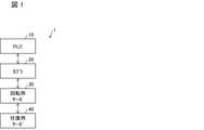
図1は、本実施形態に係るネジ締めシステム1の概要を示すブロック図である。図1に示すように、ネジ締めシステム1は、PLC(Programmable Logic Controller)10(ネジ締め不良判定装置)、カプラ20、回転用サーボ30(第1モータ)、および往復用サーボ40(第2モータ)を備える。ネジ締めシステム1は、後述するドライバー51(図2参照)の、軸周りでの回転運動および軸方向への往復運動により、ネジ締め動作を行う。このとき、PLC10は、ネジ締め動作の制御を行うとともに、当該ネジ締め動作における不良の発生および種類を判定する。§1 Application example FIG. 1 is a block diagram showing an outline of the screw tightening system 1 according to the present embodiment. As shown in FIG. 1, the screw tightening system 1 includes a PLC (Programmable Logic Controller) 10 (screw tightening defect determination device), a
本明細書においては、ネジ締め動作における不良とは、ネジに規定のトルクが与えられたにもかかわらず、当該ネジが十分な締結力を発揮しない状態を意味する。不良の例を以下に列挙する。
・ネジ山不良:ネジ山が切れていない。
・底付き:ネジがネジ穴よりも長い、または異物がネジ穴に溜まっているなどの理由で、ネジ締め動作が途中で止まる。
・異物挟み込み:ネジの座面の下に異物が挟み込まれている。
・斜め締め:ネジがネジ穴に対して傾いた状態でネジ締め動作が行われている。
・雄/雌ネジ破壊:雄ネジ、または雌ネジのネジ山が破壊されている。
・カムアウト:ネジ頭の溝が潰れ、ドライバーとネジ頭の溝(十字穴)が噛み合っていない。
・ネジ締め位置ずれ:ネジがネジ穴の位置から外れた位置に配された状態でネジ締め動作が行われている。
・ネジなし:ネジ締めの開始前にネジを落とすなどして、ネジ締め動作の開始時点でネジが存在しない。In the present specification, a defect in the screw tightening operation means a state in which the screw does not exert a sufficient tightening force even though a specified torque is applied to the screw. Examples of defects are listed below.
-Screw thread defect: The screw thread is not cut.
-With bottom: The screw tightening operation stops halfway because the screw is longer than the screw hole or foreign matter has accumulated in the screw hole.
-Foreign matter pinching: Foreign matter is pinched under the seating surface of the screw.
-Slanting tightening: The screw tightening operation is performed with the screw tilted with respect to the screw hole.
-Male / female thread destruction: The thread of the male or female thread is destroyed.
-Come out: The groove of the screw head is crushed, and the screwdriver and the groove (cross hole) of the screw head are not engaged.
-Screw tightening position deviation: The screw tightening operation is performed with the screw placed at a position off the screw hole position.
-No screw: There is no screw at the start of the screw tightening operation, such as dropping the screw before starting the screw tightening.
回転用サーボ30は、ドライバー51の軸周りの回転運動を生じさせるモータである。また、回転用サーボ30は、自身の回転速度(deg./s)、回転量(deg.)、および回転トルク(定格トルクに対する割合(%))をカプラ20へ出力する。 The
往復用サーボ40は、ドライバー51の軸方向への往復運動を生じさせるモータである。また、往復用サーボ40は、自身の回転によるドライバー51の移動速度(mm/s)、移動位置(mm)、および移動トルク(定格トルクに対する割合(%))をカプラ20へ出力する。 The reciprocating
カプラ20は、PLC10と、回転用サーボ30および往復用サーボ40と、を接続する。詳細には、カプラ20は、PLC10から受信した制御信号を回転用サーボ30および往復用サーボ40へ送信する。また、カプラ20は、回転用サーボ30から受信した、回転用サーボ30の回転速度、回転量および回転トルクをPLC10へ送信する。また、カプラ20は、往復用サーボ40から受信した、往復用サーボ40の回転によるドライバー51の移動速度、移動位置および移動トルクをPLC10へ送信する。 The
以下の説明では、回転用サーボ30の回転速度、回転量および回転トルク、並びに往復用サーボ40の回転によるドライバー51の移動速度、移動位置および移動トルクを総称してパラメータと称することがある。 In the following description, the rotation speed, rotation amount, and rotation torque of the
図2は、PLC10の構成を示すブロック図である。PLC10は、ネジ締めシステム1の動作を制御する。図2に示すように、PLC10は、制御部11、通信部12、および判定部13を備える。 FIG. 2 is a block diagram showing the configuration of PLC10. The
制御部11は、回転用サーボ30および往復用サーボ40を制御するための制御信号を通信部12へ出力する。通信部12は、制御部11から入力された制御信号をカプラ20へ送信する。制御信号は、カプラ20を介して回転用サーボ30および往復用サーボ40へ送信され、回転用サーボ30および往復用サーボ40を制御する。制御部11は、回転用サーボ30および往復用サーボ40を同期させて制御する。また、制御部11は、回転用サーボ30および往復用サーボ40のパラメータを当該回転用サーボ30および往復用サーボ40制御にフィードバックする。 The
通信部12は、回転用サーボ30および往復用サーボ40から、カプラ20を介してパラメータを受信する。通信部12は、受信したパラメータを図示しない記憶装置に記憶させる。また、受信したパラメータを記憶するための記憶装置を、ネジ締めシステム1が備えていてもよい。制御部11および判定部13は、必要に応じてパラメータを記憶装置から取得する。なお、簡単のため、図2においては、通信部12がパラメータを制御部11および判定部13へ出力している。 The
判定部13は、回転用サーボ30の回転速度、回転量および回転トルク、並びに、往復用サーボ40によるドライバー51の移動速度、移動位置および移動トルクのうち、いずれかに基づいて、ネジ締めの不良を判定する。具体的には、判定部13は、例えば回転用サーボ30の回転速度、または往復用サーボ40の移動トルクに基づいて、ネジ締めにおける不良の発生および種類を判定してもよい。また、判定部13は、例えば回転用サーボ30の回転速度、回転量および回転トルク、並びに、往復用サーボ40による移動速度、移動位置および移動トルクのいずれかに基づいて算出される、2以上のパラメータに基づいて、ネジ締めにおける不良の発生および種類を判定してもよい。判定部13による判定の具体例については後述する。 The
§2 構成例
(ネジ締めシステム1の構成)
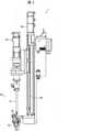
図3は、本実施形態に係るネジ締めシステム1の外観の例を示す図である。図3に示すように、ネジ締めシステム1は、回転用サーボ30、往復用サーボ40、ドライバーユニット50および支柱60を備える。また、図3には表れていないが、ネジ締めシステム1は、上述したとおり、PLC10およびカプラ20も備える。§2 Configuration example (configuration of screw tightening system 1)
FIG. 3 is a diagram showing an example of the appearance of the screw tightening system 1 according to the present embodiment. As shown in FIG. 3, the screw tightening system 1 includes a
ドライバーユニット50は、ネジ締めを行うユニットである。ドライバーユニット50は、ドライバー51と、ネジ保持部52とを備える。ドライバー51は、軸周りで回転運動しながら軸方向に往復運動することで、ネジ締め動作を実行する。以下の説明では、ドライバー51の軸方向のうち、ネジ締めの過程でドライバー51が移動する方向を下方と称する。 The
回転用サーボ30は、ドライバー51の上方に配され、ドライバー51の軸周りの回転運動を生じさせる。また、ネジ保持部52は、ドライバー51の下方に設けられ、ドライバー51によるネジ締めの対象となるネジを保持する。 The
支柱60は、ドライバーユニット50を上下に移動可能に支持する。往復用サーボ40は、支柱60の上部に設けられ、ボールネジ(不図示)を介してドライバーユニット50と接続されている。往復用サーボ40の回転運動が、ボールネジにより上下方向への直線運動に変換される。その結果、ドライバーユニット50が上下に往復運動する。 The
(ネジ締め動作)
ネジ締めシステム1によるネジ締めの動作は、以下のとおりである。まず、ネジを保持した状態のネジ保持部52が、ネジ締めを行う対象であるワーク(不図示)の、ネジ締めを行う箇所へネジを降下させる。次に、ドライバー51は、ネジが仮着座するまで、ネジ締めを行う箇所へネジを回転させながら押し当てる。ここで、仮着座とは、ネジの座面がワークに接触した状態を指す。本実施形態では、回転用サーボ30の回転トルクが50%に到達した状態を、ネジが仮着座した状態とする。(Screw tightening operation)
The screw tightening operation by the screw tightening system 1 is as follows. First, the
ネジ締めシステム1は、ネジが仮着座した状態から、さらにネジを回転させながら押し当てることで、本締めを行う。本実施形態では、本締めは、回転用サーボ30の回転トルクが150%(第1所定値)に到達するまで行われる。回転トルクが150%に到達すると、ネジ締めシステム1は、ネジを押し当てることをやめ、回転トルクが150%以上である状態を100msの間保持する。 The screw tightening system 1 performs final tightening by pressing the screw while rotating it from the state where the screw is temporarily seated. In the present embodiment, the final tightening is performed until the rotation torque of the
その後、回転用サーボ30の回転トルクが0%以下になるようにして、ネジを解放する。さらに、ドライバー51を上方へ移動させて元の位置に復帰させることで、ネジ締め動作が完了する。ただし、上述した回転トルクおよび保持時間は一例であり、ネジの種類および締結物/被締結物の種類によって異なる。 After that, the screw is released so that the rotation torque of the
なお、上述したネジ締め動作の例は、ネジ締めを行う箇所に雌ネジが予め切られた状態(タップ)のワークに対してネジ締めを行うものである。しかし、ネジ締めシステム1は、ネジ締めを行う箇所に雌ネジが切られていない状態(タッピン(セルフタップ))のワークに対してネジ締めを行うことも可能である。 In the above-mentioned example of the screw tightening operation, the screw is tightened to the work in which the female screw is cut in advance (tap) at the place where the screw is tightened. However, the screw tightening system 1 can also perform screw tightening on a work in which a female screw is not cut at a position where the screw is tightened (tapping (self-tap)).
タッピンのワークに対してネジ締めを行う場合には、ネジが仮着座していない場合であっても、回転用サーボ30の回転トルクが50%以上に到達する。そこで、タッピンのワークに対してネジ締めを行う場合には、回転用サーボ30の回転トルクが100%に到達した状態を、ネジが仮着座した状態とする。ただし、タッピンのワークに対してネジ締めを行う場合にネジが仮着座した状態とする回転用サーボ30の回転トルクは、異なる値であってもよい。 When the screw is tightened to the tapping work, the rotation torque of the
§3 動作例
以下に、判定部13による、ネジ締め動作における不良の発生および種類の判定について説明する。§3 Operation example The following describes how the
<3.1 単一パラメータによる判定>
(雄/雌ネジ破壊およびカムアウト)
雄ネジまたは雌ネジが破壊されると、ネジとワークとの間での摩擦力が小さくなる。換言すれば、ネジがネジ穴に対して空回りする。このため、雄ネジまたは雌ネジが破壊された場合、回転用サーボ30の回転速度は、雄ネジまたは雌ネジが破壊されていない場合よりも高速になる。<3.1 Judgment by a single parameter>
(Male / female screw destruction and come out)
When the male or female screw is destroyed, the frictional force between the screw and the work is reduced. In other words, the screw spins idly with respect to the screw hole. Therefore, when the male screw or the female screw is broken, the rotation speed of the
図4は、雌ネジ破壊が生じた場合における、回転用サーボ30の一回のネジ締め動作における最大回転速度値の変化を示すグラフである。図4において、横軸は時間、縦軸は回転用サーボ30の、一回のネジ締め動作における最大回転速度値を示す。また、雌ネジ破壊が生じたサンプルに切り替わった時刻を時刻T1としている。 FIG. 4 is a graph showing changes in the maximum rotation speed value in one screw tightening operation of the
図4に示す例では、時刻T1よりも前には、回転用サーボ30の最大回転速度は3000deg./s程度でほぼ一定である。一方、図4において楕円で囲んで示すとおり、時刻T1以降には、回転用サーボ30の最大回転速度は3200deg./sよりも大きくなる。ただし、図4に示した値は一例であり、ネジの種類および締結物/被締結物の種類によって異なる。 In the example shown in FIG. 4, before the time T1, the maximum rotation speed of the
また、カムアウトが発生した場合、ドライバー51がネジに対して空回りする。このため、カムアウトが発生した場合には、雄ネジまたは雌ネジが破壊された場合と同様、回転用サーボ30の最大回転速度は、カムアウトが発生していない場合よりも高速になる。 Further, when a come-out occurs, the
図5は、カムアウトが生じた場合における、回転用サーボ30の一回のネジ締め動作における最大回転速度値の変化を示すグラフである。図5において、横軸は時間、縦軸は回転用サーボ30の、一回のネジ締め動作における最大回転速度値を示す。また、カムアウトが生じるサンプルに切り替わった時刻を時刻T2としている。 FIG. 5 is a graph showing changes in the maximum rotation speed value in one screw tightening operation of the
図5に示す例では、時刻T2よりも前には、雌ネジ破壊が生じる前と同様、回転用サーボ30の最大回転速度は3000deg./s程度でほぼ一定である。一方、図5において楕円で囲んで示すとおり、時刻T2においてカムアウトが生じるサンプルに切り替わった直後には、回転用サーボ30の最大回転速度は4000deg./s程度まで上昇する。その後、回転用サーボ30の最大回転速度は3300deg./s程度まで低下するが、依然としてカムアウトが生じるサンプルに切り替わる前よりも高い回転速度である。 In the example shown in FIG. 5, before the time T2, the maximum rotation speed of the
したがって、PLC10は、回転用サーボ30の回転速度が所定の値以上である場合に、不良の種類が雌ネジの破壊、またはカムアウトであると判定する。回転用サーボ30の回転速度により、ドライバー51が必要以上の速度で回転しているか否かが分かる。したがって、PLC10は、雌ネジの破壊、またはカムアウトといった、ドライバー51が空回りする不良が発生した場合に、回転用サーボ30の回転速度に基づいてそのことを判定できる。 Therefore, when the rotation speed of the
所定の値は、図4および図5に示した例では例えば3200deg/s以上とすればよいが、これに限らない。また、不良の種類が雌ネジの破壊またはカムアウトのどちらであるかについては、例えばユーザが目視により判別すればよい。 The predetermined value may be, for example, 3200 deg / s or more in the examples shown in FIGS. 4 and 5, but is not limited to this. Further, for example, the user may visually determine whether the type of defect is the destruction of the female screw or the come-out.
また、PLC10は、本締めが行われている場合、具体的には、回転用サーボ30の回転トルクが目標値の150%以上であり、かつ、ドライバー51の軸方向への移動が行われている場合に、上記の判定を行うことが好ましい。上記の場合に判定を行うことで、PLC10は、雌ネジの破壊、またはカムアウトについて適切に判定することができる。ただし、回転用サーボ30の回転トルクについての150%という値は一例であり、これに限らない。 Further, when the
また、ネジ締めシステム1は、ネジ締め動作を複数のステップに分割し、回転用サーボ30およびドライバー51の移動の状態に応じたステップの種類を示すデータを生成するステップデータ生成部を備えていてもよい。この場合、PLC10は、例えば回転用サーボ30の回転トルクが目標値の150%以上であり、かつ、ドライバー51の軸方向への移動が行われているステップを示すデータを受信した場合に上記の判定を行えばよい。 Further, the screw tightening system 1 includes a step data generation unit that divides the screw tightening operation into a plurality of steps and generates data indicating the types of steps according to the movement state of the
(異物挟み込み)
異物挟み込みの判定について以下に説明する。異物挟み込みとは、ネジの座面とワークとの間に異物が挟み込まれる不良を指す。ここでいう異物の例としては、はんだ、アルミニウム片、樹脂片、またはコーティング剤などが挙げられる。(Foreign matter pinched)
The determination of foreign matter pinching will be described below. Foreign matter pinching refers to a defect in which a foreign matter is pinched between the seat surface of the screw and the work. Examples of the foreign matter referred to here include solder, aluminum pieces, resin pieces, coating agents, and the like.
図6は、異物挟み込みが生じた場合における、往復用サーボ40の回転によるドライバー51の移動トルクの、一回のネジ締め動作における最小値の変化を示すグラフである。図6においては、横軸は時間、縦軸は一回のネジ締め動作における移動トルクの最小値をそれぞれ示す。往復用サーボ40の移動トルクについて、負の移動トルクとは、ドライバー51を上方に移動させる方向の移動トルクである。また、図6においては、異物挟み込みが生じたサンプルに切り替わった時刻を時刻T3として示している。 FIG. 6 is a graph showing a change in the minimum value of the moving torque of the
図6に示す例では、往復用サーボ40の移動トルクの最小値は、時刻T3までは-70%前後の値をとり、そのばらつきは小さい。しかしながら、図6において楕円で囲んで示すとおり、時刻T3以降では、往復用サーボ40の移動トルクの最小値は急激に低下して-100%前後の値をとるようになり、そのばらつきが大きくなる。 In the example shown in FIG. 6, the minimum value of the moving torque of the reciprocating
このように、異物挟み込みが生じると、往復用サーボ40の移動トルクの最小値が低下する。このため、PLC10は、往復用サーボ40の移動トルクの最小値が所定の値以下になった場合に、不良の種類が異物の挟み込みであると判定する。往復用サーボ40の移動トルクにより、ドライバー51が必要以上の移動トルクで移動しているか否かが分かる。したがって、PLC10は、異物の挟み込みが発生した場合に、往復用サーボ40の移動トルクに基づいてそのことを判定できる。異物の挟み込みが生じていると判定するための、往復用サーボ40の移動トルクの最小値についての所定の値は、例えば-80%としてよい。 As described above, when the foreign matter is pinched, the minimum value of the moving torque of the reciprocating
また、PLC10は、回転用サーボ30の回転トルクが解放され、かつ、ドライバー51が原点復帰中である場合に、上記の判定を行うことが好ましい。ここで、回転トルクが解放されている場合とは、回転トルクが0%以下になっている場合を指す。また、原点とはネジ締め動作の開始時におけるドライバー51の位置を指す。上記の場合に判定を行うことで、PLC10は、異物の挟み込みについて適切に判定することができる。ただし、回転トルクが解放されている場合の回転トルクは、上記の0%に限らない。 Further, it is preferable that the
<3.2 複数パラメータによる判定>
次に、複数のパラメータを用いた判定方法について以下に説明する。以下の説明では、各パラメータについて、以下の通り表現する。
・回転用サーボ30の回転速度:R軸速度
・回転用サーボ30の回転量:R軸位置
・回転用サーボ30の回転トルク:R軸トルク
・往復用サーボ40によるドライバー51の移動速度:Z軸速度
・往復用サーボ40によるドライバー51の移動位置:Z軸位置
・往復用サーボ40によるドライバー51の移動トルク:Z軸トルク
これらの表現は、図7および図8においても用いられている。また、図7および図8においては、パラメータのばらつきを示す標準偏差をσと表現するとともに、パラメータが所定値以上であることを「大」、所定値以下であることを「小」と表現している。なお、パラメータのばらつきを示す指標としては、標準偏差に限らず、分散であってもよい。<3.2 Judgment by multiple parameters>
Next, a determination method using a plurality of parameters will be described below. In the following description, each parameter is expressed as follows.
-Rotation speed of the rotation servo 30: R-axis speed-Rotation amount of the rotation servo 30: R-axis position-Rotation torque of the rotation servo 30: R-axis torque-Movement speed of the
また、判定部13は、回転用サーボ30の回転トルクが50%(第1所定値)以上かつ150%(第2所定値)未満であり、かつ往復用サーボ40の移動トルクが50%(第3所定値)である期間を本締め中の期間と判定する。また、判定部13は、回転用サーボ30の回転トルクが150%(第2所定値)であり、かつ往復用サーボ40の移動トルクが50%(第3所定値)である期間を本締め保持中の期間と判定する。さらに、判定部13は、回転用サーボ30の回転トルクが50%未満であり、かつドライバーユニット50の軸方向への移動が行われている期間を仮着座までの期間と判定する。なお、上記の第1~第3所定値は一例であり、別の値であってもよい。ただし、第2所定値は第1所定値よりも大きい値である。 Further, in the
(第1の具体例)
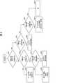
図7は、ネジ締めにおける不良を、判定部13が複数のパラメータにより判定する方法の、一例を示す図である。(First specific example)
FIG. 7 is a diagram showing an example of a method in which the
まず、判定部13は、本締め中におけるR軸位置の平均が所定値以上であるか否か判定する(SA1)。換言すれば、判定部13は、パラメータとして、本締め中における回転用サーボ30の回転量を用いる。これにより、本締め中のドライバー51が必要以上に回転しているか否かが分かる。 First, the
本締め中におけるR軸位置の平均が所定値以上である場合(SA1でYES)、さらに判定部13は、本締め保持中におけるZ軸位置の平均が所定値以上であるか判定する(SA2)。換言すれば、判定部13は、パラメータとして、本締め保持中における往復用サーボ40による移動位置を用いる。これにより、本締め保持中のドライバー51の位置が分かる。 When the average of the R-axis positions during the final tightening is equal to or greater than a predetermined value (YES in SA1), the
本締め保持中におけるZ軸位置の平均が所定値以上でない場合(SA2でNO)、判定部13は、ネジなしの不良が生じたと判定する(SA3)。本締め保持中におけるZ軸位置の平均が所定値以上である場合(SA2でYES)、さらに判定部13は、本締め中におけるR軸トルクのばらつきが所定値以下であるか判定する(SA4)。換言すれば、判定部13は、パラメータとして、本締め中における回転用サーボ30の回転トルクのばらつきを用いる。これにより、本締め中におけるドライバー51の回転トルクのばらつきが分かる。本締め中において、カムアウトが発生している場合には、ドライバー51が動くことがある。また、本締め中において、雄/雌ネジ破壊、またはネジ山の不良が発生している場合には、ネジが動くことがある。このため、ドライバー51の回転速度を一定に維持しようとすると、回転トルクにばらつきが生じる。したがって、PLC10は、ネジ締め動作においてカムアウト、雄/雌ネジ破壊、またはネジ山の不良が発生している場合にそのことを判定できる。 When the average of the Z-axis positions during the final tightening holding is not equal to or more than a predetermined value (NO in SA2), the
本締め中におけるR軸トルクのばらつきが所定値以下でない場合(SA4でNO)、判定部13は、カムアウトの不良が生じたと判定する(SA5)。本締め中におけるR軸トルクのばらつきが所定値以下である場合(SA4でYES)、判定部13は、雌ネジ破壊の不良が生じたと判定する(SA6)。 When the variation of the R-axis torque during the final tightening is not equal to or less than a predetermined value (NO in SA4), the
ステップSA1に戻って、本締め中におけるR軸位置の平均が所定値以上でない場合(SA1でNO)、判定部13は、本締め保持中におけるZ軸位置の平均が所定値以下であるか判定する(SA7)。換言すれば、判定部13は、パラメータとして、往復用サーボ40による移動位置を用いる。 Returning to step SA1, when the average of the R-axis positions during the final tightening is not equal to or higher than the predetermined value (NO in SA1), the
本締め保持中におけるZ軸位置の平均が所定値以下である場合(SA7でYES)、さらに判定部13は、本締め保持中におけるZ軸速度のばらつきが所定値以上であるか判定する(SA8)。換言すれば、判定部13は、パラメータとして、往復用サーボ40による移動速度を用いる。これにより、本締め保持中のドライバー51の移動速度が分かる。本締め保持中には、通常、ドライバー51は軸方向に移動しない。しかし、底付き、異物挟み込み、または位置ズレの不良が発生している場合には、ネジが正しく締まっていないために、ネジが動くことがあるため、ドライバー51が軸方向に移動することがある。したがって、PLC10は、ネジ締め動作において底付き、異物挟み込み、または位置ズレの不良が発生している場合にそのことを判定できる。 When the average of the Z-axis positions during the final tightening holding is equal to or less than the predetermined value (YES in SA7), the
本締め保持中におけるZ軸速度のばらつきが所定値以上である場合(SA8でYES)、判定部13は、底付きの不良が生じたと判定する(SA9)。本締め保持中におけるZ軸速度のばらつきが所定値以上でない場合(SA8でNO)、判定部13は、(i)異物挟み込みの不良が生じた、または(ii)0.1mm程度のネジ締め位置のズレの不良が生じた、のいずれかであると判定する(SA10)。この場合には、どちらの不良が生じているかについては、ネジ締めシステム1のユーザなどが目視で確認すればよい。 When the variation in the Z-axis speed during the final tightening holding is equal to or greater than a predetermined value (YES in SA8), the
ステップSA7に戻って、本締め保持中におけるZ軸位置の平均が所定値以下でない場合(SA7でNO)、判定部13は、本締め保持中におけるZ軸速度のばらつきが所定値以上であるか判定する(SA11)。換言すれば、判定部13は、パラメータとして、本締め保持中における往復用サーボ40による移動位置の平均を用いる。 Returning to step SA7, when the average of the Z-axis positions during the final tightening holding is not equal to or less than the predetermined value (NO in SA7), the
本締め保持中におけるZ軸速度のばらつきが所定値以上である場合(SA11でYES)、判定部13は、3°~4°傾いた斜め締めの不良が生じたと判定する(SA12)。本締め保持中におけるZ軸速度のばらつきが所定値以上である場合(SA11でNO)、判定部13は、(i)不良が生じなかった、(ii)1°~2°傾いた斜め締めの不良が生じた、または(iii)0.1mmまたは0.5mm~0.9mm程度のネジ締め位置のズレの不良が生じた、のいずれかであると判定する(SA13)。この場合には、実際の不良の有無、および不良が生じていた場合における当該不良の種類については、ネジ締めシステム1のユーザなどが目視で確認すればよい。 When the variation in the Z-axis speed during the final tightening holding is equal to or greater than a predetermined value (YES in SA11), the
以上のとおり、図7に示した方法によれば、判定部13は、複数のパラメータに基づいて、ネジ締めにおける様々な種類の以上について判定することができる。なお、各ステップにおける所定値は、任意に別個の値を設定されてもよいことは言うまでもない。 As described above, according to the method shown in FIG. 7, the
(第2の具体例)
図8は、ネジ締めにおける不良を、判定部13が複数のパラメータにより判定する方法の、別の例を示す図である。(Second specific example)
FIG. 8 is a diagram showing another example of a method in which the
まず、判定部13は、本締め中におけるR軸位置の平均が所定値以上であるか判定する(SB1)。本締め中におけるR軸位置の平均が所定値以上である場合(SB1でYES)、判定部13は、本締め中におけるR軸トルクのばらつきが所定値以下であるか判定する(SB2)。換言すれば、判定部13は、パラメータとして、本締め中における回転用サーボ30の回転トルクのばらつきを用いる。これにより、本締め保持中におけるドライバー51の回転トルクのばらつきが分かる。本締め保持中には、通常、ネジおよびドライバー51は回転しない。しかし、ネジ頭が不完全に破壊されたカムアウトが発生している場合には、ドライバー51が動くことがあるため、回転トルクのばらつきが大きくなる。したがって、PLC10は、ネジ締め動作においてネジ頭が不完全に破壊されたカムアウトの不良が発生している場合にそのことを判定できる。 First, the
本締め中におけるR軸トルクのばらつきが所定値以下でない場合(SB2でNO)、判定部13は、ネジ山に不良が発生していると判定する(SB3)。ステップSB3で判定部13が判定するネジ山の不良は、ネジ山の下半分または下4分の1など、主にネジの下側に不良が発生しているものである。 When the variation of the R-axis torque during the final tightening is not equal to or less than a predetermined value (NO in SB2), the
本締め中におけるR軸トルクのばらつきが所定値以下である場合(SB2でYES)、判定部13は、仮着座までにおけるZ軸位置のばらつきが所定値以下であるか判定する(SB4)。換言すれば、判定部13は、パラメータとして、仮着座までにおける往復用サーボ40による移動位置のばらつきを用いる。これにより、仮着座までの期間における、ドライバー51の移動位置のばらつきが分かる。カムアウトの不良が発生している場合には、ネジが穴に入っていかないため、ドライバー51のZ軸方向の移動位置のばらつきは小さい。一方、雄ネジ破壊の不良が発生している場合には、ネジは穴に入っていくため、ドライバー51のZ軸方向の移動位置に変化が生じ、ばらつきが大きくなる。したがって、PLC10は、ネジ締め動作においてカムアウトまたは雌ネジ破壊の不良が発生している場合に、どちらの不良が発生しているか判定できる。 When the variation of the R-axis torque during the final tightening is not more than a predetermined value (YES in SB2), the
仮着座までにおけるZ軸位置のばらつきが所定値以下でない場合(SB4でNO)、判定部13は、雌ネジ破壊の不良が生じていると判定する(SB5)。このとき、判定部13は、雌ネジの破壊が完全か不完全化に関わらず、当該不良が生じていると判定できる。一方、仮着座までにおけるZ軸位置のばらつきが所定値以下である場合(SB4でYES)、判定部13は、カムアウトの不良が生じていると判定する(SB6)。ステップSB6で判定部13が判定するカムアウトは、ネジ頭の溝が完全に破壊された状態のカムアウトである。 When the variation in the Z-axis position up to the temporary seating is not equal to or less than a predetermined value (NO in SB4), the
ステップSB1に戻って、本締め中におけるR軸位置の平均が所定値以上でない場合(SB1でNO)、判定部13は、本締め保持中におけるR軸トルクのばらつきが所定値以上であるか判定する(SB7)。本締め保持中におけるR軸トルクのばらつきが所定値以上である場合(SB7でYES)、判定部13は、カムアウトの不良が生じていると判定する(SB8)。ステップSB8で判定部13が判定するカムアウトは、ステップSB6とは異なり、ネジ頭の溝の破壊が不完全な状態のカムアウトである。 Returning to step SB1, when the average of the R-axis positions during final tightening is not equal to or greater than a predetermined value (NO in SB1), the
本締め保持中におけるR軸トルクのばらつきが所定値以上でない場合(SB7でNO)、判定部13は、本締め保持中におけるR軸速度のばらつきが所定値以上であるか判定する(SB9)。換言すれば、判定部13は、パラメータとして、本締め保持中における回転用サーボ30の回転速度のばらつきを用いる。これにより、本締め保持中のドライバー51の回転速度のばらつきが分かる。本締め保持中には、通常、ドライバー51は回転しない。しかし、ネジ山の上側が破壊される不良が発生している場合には、雄ネジと雌ネジとが正しく噛み込んでいないため、本締め保持中においてもネジが回転することがある。このため、本締め保持中のドライバー51の回転速度のばらつきが大きくなる。したがって、PLC10は、ネジ締め動作においてネジ山の上側が破壊される不良が発生している場合にそのことを判定できる。 When the variation of the R-axis torque during the final tightening holding is not equal to or more than a predetermined value (NO in SB7), the
本締め保持中におけるR軸速度のばらつきが所定値以上である場合(SB9でYES)、判定部13は、ネジ山に不良が発生していると判定する(SB10)。ステップSB10で判定部13が判定するネジ山の不良は、ステップSB3とは異なり、ネジ山の上半分の破壊、または上4分の1の破壊など、主にネジの上側に不良が発生しているものである。一方、本締め保持中におけるR軸速度のばらつきが所定値以上でない場合(SB9でNO)、判定部13は、ネジ締めの動作において不良が発生していないと判定する(SB11)。 When the variation in the R-axis speed during the final tightening holding is equal to or greater than a predetermined value (YES in SB9), the
なお、ステップSB5およびSB6において判定されるような、雌ネジ破壊またはカムアウトといった不良が生じている場合、回転用サーボ30の回転トルクが50%に到達せず、本締めが開始されない虞がある。このような場合には、判定部13は、例えば所定の時間が経過することを条件として、仮着座までのR軸位置の平均またはR軸トルクのばらつきを参照してもよい。 If a defect such as female screw breakage or come-out as determined in steps SB5 and SB6 occurs, the rotational torque of the
以上のとおり、図8に示した方法によっても、判定部13は、複数のパラメータに基づいて、ネジ締めにおける様々な種類の以上について判定することができる。また、判定部13は、図7および図8に示した例のいずれとも異なる方法で、ネジ締め動作における不良の発生および種類を判定してもよい。さらに、判定部13は、図4~図6を参照して説明した、単一のパラメータを用いた判定方法と、図7または図8を参照して説明した、複数のパラメータを用いた判定方法とを組み合わせて、ネジ締め動作における不良の発生および種類を判定してもよい。 As described above, also by the method shown in FIG. 8, the
§4 変形例
ネジ締めシステム1の制御ブロック(特に制御部11、通信部12および判定部13)は、集積回路(ICチップ)等に形成された論理回路(ハードウェア)によって実現してもよいし、ソフトウェアによって実現してもよい。§4 Modification example The control block (particularly the
後者の場合、ネジ締めシステム1は、各機能を実現するソフトウェアであるプログラムの命令を実行するコンピュータを備えている。このコンピュータは、例えば1つ以上のプロセッサを備えていると共に、上記プログラムを記憶したコンピュータ読み取り可能な記録媒体を備えている。そして、上記コンピュータにおいて、上記プロセッサが上記プログラムを上記記録媒体から読み取って実行することにより、本発明の目的が達成される。上記プロセッサとしては、例えばCPU(Central Processing Unit)を用いることができる。上記記録媒体としては、「一時的でない有形の媒体」、例えば、ROM(Read Only Memory)等の他、テープ、ディスク、カード、半導体メモリ、プログラマブルな論理回路などを用いることができる。また、上記プログラムを展開するRAM(Random Access Memory)などをさらに備えていてもよい。また、上記プログラムは、該プログラムを伝送可能な任意の伝送媒体(通信ネットワークや放送波等)を介して上記コンピュータに供給されてもよい。なお、本発明の一態様は、上記プログラムが電子的な伝送によって具現化された、搬送波に埋め込まれたデータ信号の形態でも実現され得る。 In the latter case, the screw tightening system 1 includes a computer that executes instructions of a program that is software that realizes each function. The computer includes, for example, one or more processors and a computer-readable recording medium that stores the program. Then, in the computer, the processor reads the program from the recording medium and executes the program, thereby achieving the object of the present invention. As the processor, for example, a CPU (Central Processing Unit) can be used. As the recording medium, a "non-temporary tangible medium", for example, a ROM (Read Only Memory) or the like, a tape, a disk, a card, a semiconductor memory, a programmable logic circuit, or the like can be used. Further, a RAM (Random Access Memory) for expanding the above program may be further provided. Further, the program may be supplied to the computer via any transmission medium (communication network, broadcast wave, etc.) capable of transmitting the program. It should be noted that one aspect of the present invention can also be realized in the form of a data signal embedded in a carrier wave, in which the above program is embodied by electronic transmission.
本発明は上述した各実施形態に限定されるものではなく、請求項に示した範囲で種々の変更が可能であり、異なる実施形態にそれぞれ開示された技術的手段を適宜組み合わせて得られる実施形態についても本発明の技術的範囲に含まれる。 The present invention is not limited to the above-described embodiments, and various modifications can be made within the scope of the claims, and the embodiments obtained by appropriately combining the technical means disclosed in the different embodiments. Is also included in the technical scope of the present invention.
1 ネジ締めシステム
10 PLC(ネジ締め不良判定装置)
30 回転用サーボ(第1モータ)
40 往復用サーボ(第2モータ)
51 ドライバー1 Screw tightening
Servo for 30 rotations (1st motor)
40 Reciprocating servo (second motor)
51 driver
Claims (9)
Translated fromJapanese前記第1モータの回転トルクが第1所定値以上かつ第2所定値未満であり、かつ、前記第2モータの移動トルクが第3所定値である期間を本締め中の期間と判定し、前記第1モータの回転トルクが前記第2所定値であり、かつ、前記第2モータの移動トルクが第3所定値である期間を本締め保持中の期間と判定し、前記パラメータとして前記本締め保持中における前記第2モータによる前記移動速度を用いることを特徴とするネジ締め不良判定装置。(I) Rotational speed, amount and torque of the first motor that causes the driver to rotate around the axis for tightening the screw, and (ii) that causes the driver to reciprocate in the axial direction. Based on two or more parameters calculated based on either the moving speed, the moving position, and the moving torque of the second motor, the occurrence and type of defects in the screw tightening operation by the driver are determined.
The period in which the rotational torque of the first motor is equal to or greater than the first predetermined value and less than the second predetermined value and the moving torque of the second motor is the third predetermined value is determined to be the period during final tightening. The period in which the rotational torque of the first motor is the second predetermined value and the moving torque of the second motor is the third predetermined value is determined to be the period during the final tightening holding, and the final tightening holding is performed as the parameter. A screw tightening defect determining device, characterized in that themoving speed of the second motor is used .
前記第1モータの回転トルクが第1所定値以上かつ第2所定値未満であり、かつ、前記第2モータの移動トルクが第3所定値である期間を本締め中の期間と判定し、前記第1モータの回転トルクが前記第2所定値であり、かつ、前記第2モータの移動トルクが第3所定値である期間を本締め保持中の期間と判定し、前記パラメータとして、前記本締め中における前記第1モータの回転量、および前記本締め中における前記第1モータの前記回転トルクのばらつきを用いることを特徴とするネジ締め不良判定装置。(I) Rotational speed, amount and torque of the first motor that causes the driver to rotate around the axis for tightening the screw, and (ii) that causes the driver to reciprocate in the axial direction. Based on two or more parameters calculated based on either the moving speed, the moving position, and the moving torque of the second motor, the occurrence and type of defects in the screw tightening operation by the driver are determined.
A period in which the rotational torque of the first motor is equal to or greater than the first predetermined value and less than the second predetermined value and the moving torque of the second motor is the third predetermined value is determined to be the period during final tightening. The period in which the rotational torque of the first motor is the second predetermined value and the moving torque of the second motor is the third predetermined value is determined to be the period during the final tightening holding, and the final tightening is performed as the parameter.A screw tightening defect determining device, characterized in that variations inthe amount of rotation of the first motor and the rotational torque of the first motor during final tightening are used.
前記第1モータの回転トルクが第1所定値以上かつ第2所定値未満であり、かつ、前記第2モータの移動トルクが第3所定値である期間を本締め中の期間と判定し、前記第1モータの回転トルクが前記第2所定値であり、かつ、前記第2モータの移動トルクが第3所定値である期間を本締め保持中の期間と判定し、前記パラメータとして、前記本締め中における前記第1モータの回転量、および前記本締め保持中における前記第1モータの前記回転トルクのばらつきを用いることを特徴とするネジ締め不良判定装置。(I) Rotational speed, amount and torque of the first motor that causes the driver to rotate around the axis for tightening the screw, and (ii) that causes the driver to reciprocate in the axial direction. Based on two or more parameters calculated based on either the moving speed, the moving position, and the moving torque of the second motor, the occurrence and type of defects in the screw tightening operation by the driver are determined.
A period in which the rotational torque of the first motor is equal to or greater than the first predetermined value and less than the second predetermined value and the moving torque of the second motor is the third predetermined value is determined to be the period during final tightening. The period in which the rotational torque of the first motor is the second predetermined value and the moving torque of the second motor is the third predetermined value is determined to be the period during the final tightening holding, and the final tightening is performed as the parameter.A screw tightening defect determining device, characterized in that variations inthe amount of rotation of the first motor and the rotational torque of the first motor during holding of the final tightening are used.
前記第1モータの回転トルクが第1所定値以上かつ第2所定値未満であり、かつ、前記第2モータの移動トルクが第3所定値である期間を本締め中の期間と判定し、前記第1モータの回転トルクが前記第2所定値であり、かつ、前記第2モータの移動トルクが第3所定値である期間を本締め保持中の期間と判定し、前記パラメータとして、前記本締め中における前記第1モータの回転量、および前記本締め保持中における前記第1モータの回転速度のばらつきを用いることを特徴とするネジ締め不良判定装置。(I) Rotational speed, amount and torque of the first motor that causes the driver to rotate around the axis for tightening the screw, and (ii) that causes the driver to reciprocate in the axial direction. Based on two or more parameters calculated based on either the moving speed, the moving position, and the moving torque of the second motor, the occurrence and type of defects in the screw tightening operation by the driver are determined.
The period in which the rotational torque of the first motor is equal to or greater than the first predetermined value and less than the second predetermined value and the moving torque of the second motor is the third predetermined value is determined to be the period during final tightening. A period in which the rotational torque of the first motor is the second predetermined value and the moving torque of the second motor is the third predetermined value is determined to be the period during the final tightening holding, and the final tightening is performed as the parameter.A screw tightening defect determining device, characterized in that variations inthe amount of rotation of the first motor and the rotation speed of the first motor during holding of the final tightening are used.
前記第1モータの回転トルクが第1所定値以上かつ第2所定値未満であり、かつ、前記第2モータの移動トルクが第3所定値である期間を本締め中の期間と判定し、前記第1モータの回転トルクが前記第2所定値であり、かつ、前記第2モータの移動トルクが第3所定値である期間を本締め保持中の期間と判定し、前記パラメータとして、前記本締め中における前記第1モータの回転量、および前記第1モータの前記回転トルクが前記第1所定値未満である期間における、前記第2モータによる前記移動位置のばらつきを用いることを特徴とするネジ締め不良判定装置。(I) Rotational speed, amount and torque of the first motor that causes the driver to rotate around the axis for tightening the screw, and (ii) that causes the driver to reciprocate in the axial direction. Based on two or more parameters calculated based on either the moving speed, the moving position, and the moving torque of the second motor, the occurrence and type of defects in the screw tightening operation by the driver are determined.
A period in which the rotational torque of the first motor is equal to or greater than the first predetermined value and less than the second predetermined value and the moving torque of the second motor is the third predetermined value is determined to be the period during final tightening. The period in which the rotational torque of the first motor is the second predetermined value and the moving torque of the second motor is the third predetermined value is determined to be the period during the final tightening holding, and the final tightening is performed as the parameter. It is characterizedby using the variation of the movement position by the second motor during the period in whichthe rotation amount of the first motor and the rotation torque of the first motor are less than the first predetermined value. Ji-tightening defect judgment device.
前記ドライバーの軸方向への往復運動を生じさせる往復用サーボと、
請求項1から7のいずれか1項に記載のネジ締め不良判定装置と、を備えることを特徴とするネジ締めシステム。A rotation servo that causes rotational movement around the driver's axis,
A reciprocating servo that causes the driver to reciprocate in the axial direction,
A screw tightening system comprising the screw tightening defect determination device according to any one of claims 1 to7 .
Priority Applications (2)
| Application Number | Priority Date | Filing Date | Title |
|---|---|---|---|
| JP2018127655AJP7035859B2 (en) | 2018-07-04 | 2018-07-04 | Screw tightening defect determination device, screw tightening system and program |
| PCT/JP2019/026500WO2020009159A1 (en) | 2018-07-04 | 2019-07-03 | Screw fastening error determination device, screw fastening system, and program |
Applications Claiming Priority (1)
| Application Number | Priority Date | Filing Date | Title |
|---|---|---|---|
| JP2018127655AJP7035859B2 (en) | 2018-07-04 | 2018-07-04 | Screw tightening defect determination device, screw tightening system and program |
Publications (2)
| Publication Number | Publication Date |
|---|---|
| JP2020006452A JP2020006452A (en) | 2020-01-16 |
| JP7035859B2true JP7035859B2 (en) | 2022-03-15 |
Family
ID=69060889
Family Applications (1)
| Application Number | Title | Priority Date | Filing Date |
|---|---|---|---|
| JP2018127655AActiveJP7035859B2 (en) | 2018-07-04 | 2018-07-04 | Screw tightening defect determination device, screw tightening system and program |
Country Status (2)
| Country | Link |
|---|---|
| JP (1) | JP7035859B2 (en) |
| WO (1) | WO2020009159A1 (en) |
Families Citing this family (6)
| Publication number | Priority date | Publication date | Assignee | Title |
|---|---|---|---|---|
| WO2021153269A1 (en)* | 2020-01-27 | 2021-08-05 | 三菱電機株式会社 | Automatic screw fastening method and automatic screw fastening device |
| JP7375684B2 (en) | 2020-06-22 | 2023-11-08 | オムロン株式会社 | screw tightening device |
| EP4052851A1 (en) | 2021-03-04 | 2022-09-07 | Max Co., Ltd. | Fastening tool |
| JP2023042526A (en)* | 2021-09-14 | 2023-03-27 | マックス株式会社 | fastening tool |
| TW202322984A (en)* | 2021-09-14 | 2023-06-16 | 日商美克司股份有限公司 | fastening tool |
| JP7718195B2 (en)* | 2021-09-14 | 2025-08-05 | マックス株式会社 | Fastening tool |
Citations (1)
| Publication number | Priority date | Publication date | Assignee | Title |
|---|---|---|---|---|
| JP2013132693A (en) | 2011-12-23 | 2013-07-08 | Nitto Seiko Co Ltd | Automatic screwing device |
Family Cites Families (3)
| Publication number | Priority date | Publication date | Assignee | Title |
|---|---|---|---|---|
| JP2585750B2 (en)* | 1988-09-22 | 1997-02-26 | 本田技研工業株式会社 | Nut runner tightening quality judgment method |
| JP2953292B2 (en)* | 1994-02-07 | 1999-09-27 | 株式会社デンソー | Screw fastening device |
| EP0914910A1 (en)* | 1997-10-30 | 1999-05-12 | Yukitaka Murakami | Wrenching method and apparatus wrenching attachment, and medium storing wrenching torque control program |
- 2018
- 2018-07-04JPJP2018127655Apatent/JP7035859B2/enactiveActive
- 2019
- 2019-07-03WOPCT/JP2019/026500patent/WO2020009159A1/ennot_activeCeased
Patent Citations (1)
| Publication number | Priority date | Publication date | Assignee | Title |
|---|---|---|---|---|
| JP2013132693A (en) | 2011-12-23 | 2013-07-08 | Nitto Seiko Co Ltd | Automatic screwing device |
Also Published As
| Publication number | Publication date |
|---|---|
| JP2020006452A (en) | 2020-01-16 |
| WO2020009159A1 (en) | 2020-01-09 |
Similar Documents
| Publication | Publication Date | Title |
|---|---|---|
| JP7035859B2 (en) | Screw tightening defect determination device, screw tightening system and program | |
| KR20170072938A (en) | Numerical control device | |
| JP7070164B2 (en) | Screw tightening defect determination device, screw tightening system and program | |
| CN115551672B (en) | Screw fixing device | |
| US20210154798A1 (en) | Machine Tool And Method Of Operating A Machine Tool | |
| US8532813B2 (en) | Method of controlling thread cutting | |
| KR102475428B1 (en) | Screw length determination system, screw tightening system and recording medium | |
| JP7031558B2 (en) | Thread length determination system, screw tightening system and program | |
| JP7070467B2 (en) | Screw tightening defect judgment device, screw tightening device, screw tightening defect judgment method, and control program | |
| WO2021235041A1 (en) | Screw tightening defect determination device | |
| US6487944B2 (en) | Machine tool and control method therefor | |
| JP2020163557A (en) | Screw fastening failure determination device, screw fastening device, screw fastening failure determination method and control program | |
| WO2020195325A1 (en) | Screw fastening failure determination device, screw fastening device, screw fastening failure determination method, and control program | |
| JP7527524B1 (en) | Numerical control device and numerical control method | |
| EP0181944A1 (en) | Skipping device for dwell | |
| KR100655310B1 (en) | Automatic clamp and unclamp device and method of gravity shaft | |
| JP2001162459A (en) | Automatic screw tightening machine |
Legal Events
| Date | Code | Title | Description |
|---|---|---|---|
| A621 | Written request for application examination | Free format text:JAPANESE INTERMEDIATE CODE: A621 Effective date:20201215 | |
| A131 | Notification of reasons for refusal | Free format text:JAPANESE INTERMEDIATE CODE: A131 Effective date:20220105 | |
| A521 | Request for written amendment filed | Free format text:JAPANESE INTERMEDIATE CODE: A523 Effective date:20220125 | |
| TRDD | Decision of grant or rejection written | ||
| A01 | Written decision to grant a patent or to grant a registration (utility model) | Free format text:JAPANESE INTERMEDIATE CODE: A01 Effective date:20220201 | |
| A61 | First payment of annual fees (during grant procedure) | Free format text:JAPANESE INTERMEDIATE CODE: A61 Effective date:20220214 | |
| R150 | Certificate of patent or registration of utility model | Ref document number:7035859 Country of ref document:JP Free format text:JAPANESE INTERMEDIATE CODE: R150 |