JP7035442B2 - Hall detector - Google Patents
Hall detectorDownload PDFInfo
- Publication number
- JP7035442B2 JP7035442B2JP2017201752AJP2017201752AJP7035442B2JP 7035442 B2JP7035442 B2JP 7035442B2JP 2017201752 AJP2017201752 AJP 2017201752AJP 2017201752 AJP2017201752 AJP 2017201752AJP 7035442 B2JP7035442 B2JP 7035442B2
- Authority
- JP
- Japan
- Prior art keywords
- sound
- air passage
- detection unit
- unit
- wind noise
- Prior art date
- Legal status (The legal status is an assumption and is not a legal conclusion. Google has not performed a legal analysis and makes no representation as to the accuracy of the status listed.)
- Active
Links
- 238000001514detection methodMethods0.000claimsdescription96
- 238000005260corrosionMethods0.000claimsdescription19
- 230000007797corrosionEffects0.000claimsdescription19
- 230000007246mechanismEffects0.000description14
- 230000006870functionEffects0.000description10
- 239000000463materialSubstances0.000description5
- 238000009434installationMethods0.000description4
- 238000000034methodMethods0.000description3
- 238000004806packaging method and processMethods0.000description3
- 238000000926separation methodMethods0.000description3
- 238000010586diagramMethods0.000description2
- 230000005281excited stateEffects0.000description2
- 230000004048modificationEffects0.000description2
- 238000012986modificationMethods0.000description2
- 230000002093peripheral effectEffects0.000description2
- 239000011347resinSubstances0.000description2
- 229920005989resinPolymers0.000description2
- 238000009423ventilationMethods0.000description2
- 238000004378air conditioningMethods0.000description1
- 229910052782aluminiumInorganic materials0.000description1
- XAGFODPZIPBFFR-UHFFFAOYSA-NaluminiumChemical compound[Al]XAGFODPZIPBFFR-UHFFFAOYSA-N0.000description1
- 239000003990capacitorSubstances0.000description1
- 230000008859changeEffects0.000description1
- 238000006243chemical reactionMethods0.000description1
- 230000007423decreaseEffects0.000description1
- 230000005484gravityEffects0.000description1
- 239000004973liquid crystal related substanceSubstances0.000description1
- 239000000696magnetic materialSubstances0.000description1
- 239000007769metal materialSubstances0.000description1
- 230000008439repair processEffects0.000description1
- 150000003839saltsChemical class0.000description1
- 230000007704transitionEffects0.000description1
Images


Landscapes
- Examining Or Testing Airtightness (AREA)
Description
Translated fromJapanese本発明は、ホール検知装置に関する。 The present invention relates to a hall detection device.
例えば、特許文献1に記載されるように、包装容器の漏れを検査する装置が知られている。特許文献1に記載された装置では、検査対象である漏れを検査される包装容器内の乱流により生じる超音波信号を集音マイクにより検知することで、包装容器に漏れが無いかを検査している。 For example, as described in
従来の集音マイクでは、その構造上、集音部を風道の外面と一定の距離を隔てて保持することができないため、風道に生じる腐食孔から漏れ出る音を均一の条件において迅速、確実に集音することができない虞があった。 Due to the structure of a conventional sound collecting microphone, the sound collecting part cannot be held at a certain distance from the outer surface of the air passage, so that the sound leaking from the corrosive holes generated in the air passage can be quickly released under uniform conditions. There was a risk that the sound could not be collected reliably.
前述した課題を解決する主たる本発明は、音を検知する音検知部と、前記音検知部を風道の外面に接近させた状態において、前記音検知部と前記風道の外面とが所定の間隔を有するように、前記音検知部を保持する保持部と、前記音検知部と電気的に接続され、前記音検知部から風音を示す風音情報を取得するとともに、前記風音情報を表示する表示部と、前記音検知部を取り囲むように設けられ、前記音検知部を前記風道の外面に接近させた状態において、前記風道の外面に腐食孔を個々に囲む印をつけることが可能な押印部と、を備える。
本発明の他の特徴については、添付図面および本明細書の記載により明らかとなる。The main invention for solving the above-mentioned problems is that the sound detection unit and the outer surface of the air passage are predetermined in a state where the sound detection unit for detecting sound and the sound detection unit are brought close to the outer surface of the air passage. A holding unit that holds the sound detection unit is electrically connected to the sound detection unit so as to have an interval, and wind sound information indicating wind noise is acquired from the sound detection unit, and the wind noise information is obtained. The display unit to be displayed and the sound detection unit are provided so as to surround the sound detection unit, and when the sound detection unit is brought close to the outer surface of the air passage, the outer surface of the air passageis individually marked to surround the corrosive holes. It is equipped with a stamping part that can be used.
Other features of the invention will become apparent with reference to the accompanying drawings and the description herein.
本発明によれば、風道の外面と所定の距離を維持しながら風道の外面上を移動させることができ、風道に生じる腐食孔から漏れ出る音を検知することで、腐食孔を効率良く特定することができる。 According to the present invention, it is possible to move on the outer surface of the air passage while maintaining a predetermined distance from the outer surface of the air passage, and by detecting the sound leaking from the corroded hole generated in the air passage, the corroded hole is made efficient. Can be well identified.
本明細書および添付図面の記載により、少なくとも以下の事項が明らかとなる。以下の説明において、同一符号を付した部分は同一の要素を表し、その基本的な構成および動作は同様であるものとする。なお、以下説明においては、保持ホルダ123の長手方向をX方向(X軸)とし、伸縮部材130が接続される保持ホルダ123の一面と垂直に交わる方向をY方向(Y軸)とし、X方向およびY方向と直交する方向をZ方向(Z軸)とする。 The description of this specification and the accompanying drawings will clarify at least the following matters. In the following description, the parts with the same reference numerals represent the same elements, and their basic configurations and operations are the same. In the following description, the longitudinal direction of the
===ホール検知装置100の構成===
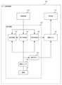
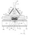
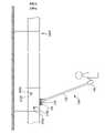
図1~図7を参照しつつ、本実施形態に係るホール検知装置100について、以下のとおり説明する。図1は、風道1200に腐食孔2000が生じている状態を示す側面図である。図2は、本実施形態に係るホール検知装置100の一例を示す構成図である。図3は、本実施形態に係るホール検知装置100の一例を示す分解斜視図である。図4は、本実施形態に係るホール検知装置100の一例を示すZ方向から見た断面図である。図5は、本実施形態に係るホール検知装置100の伸縮部材130が傾いている状態の一例を示す図4におけるX方向から見た断面図である。図6は、本実施形態に係るホール検知装置100の伸縮部材130が傾いている状態の一例を示す図4におけるZ方向から見た断面図である。図7は、本実施形態に係るホール検知装置100の使用状況を示す平面図である。なお、図5、図6においては、保持ホルダ123の内部の構造を省略して示している。=== Configuration of
The
風道装置1000は、屋外空間と屋内空間とを連通し、両者の間で通気させることにより、屋内の温度や湿度を適正な範囲に維持するための装置である。このような風道装置1000は、例えば、図1に示すように、屋外空間から外気を取り入れる外気取入れ口1100と、外気を通過させる風道1200と、風道1200を通過する外気を調和させる外気調和装置1300と、風道1200の内部に外気を通過するための送風機1400と、送風機1400を回転させる電動機1500と、電動機1500と連動する重力ダンパ1600と、を含んで構成される。 The
風道装置1000の停止は、発電所建屋内の環境を適切に維持できず発電所の運転に支障をきたすこともあるため、許されない。一方、発電所は、主に海岸部に立地していることが多く、そのため、塩の影響で建屋内と建屋外とを連通する風道1200に、腐食に起因して、外観では確認できない程度の微細な腐食孔2000が風道1200に生じることがある。このような腐食孔2000が拡大進行した場合、風道1200の通気能力が低下し、それに起因して風道装置1000が停止すると、発電所の運転の支障をきたす虞がある。 The shutdown of the
そこで、本実施形態のホール検知装置100は、風道1200内を通過する気流と腐食孔2000との間に生じる風音を検知することで微細な腐食孔2000を検知し、また、検知した腐食孔2000に印2100を付ける機能を有する。以下、ホール検知装置100について詳細に説明する。 Therefore, the
図3に示すように、ホール検知装置100は、音検知部110と、押印機構120と、伸縮部材130と、表示装置140と、を含んで構成されている。 As shown in FIG. 3, the
<<音検知部110>>
音検知部110は、風音を検知する機能を有する。音検知部1100は、例えばマイクロフォンである。マイクロフォンは、人が聞きとれる可聴周波数を検出することができ、例えばダイナミック型とコンデンサ型がある。ダイナミック型とは、磁石とコイルを用いて、コイルが振動することで逆起電力を発生させる方式である。一方、コンデンサ型とは、振動による静電容量の変化に基づいて信号を検出する方式である。本実施形態に係る音検知部110であるマイクロフォンの方式は、特に限定されない。また、音検知部110は、例えば、信号を増幅する反転増幅回路(不図示)、ピーク値を検出するコンパレータ基本回路(不図示)、SCRを用いたアラーム駆動回路(不図示)などを有し、音を検知する。<<
The
図3に示すように、音検知部110は、風音を収集する集音面111と、風音の大きさを示す情報(以下、「風音情報」と称する。)を出力する信号端子112と、を有する。腐食孔2000に生じる風音は、図4に示すように、例えば、風道1200内を通過する気流と腐食孔2000との間で生じる渦や、風道1200内から腐食孔2000を通って外部に漏れ出る気流によって生じる。風音情報は、信号端子112に接続される信号線(不図示)を通じて表示装置140に伝送される。音検知部110は、マイクフォルダ113に収容される。また、図4に示すように、音検知部110は、その集音面111が押印機構120の-Y方向の端面と面一となるように、押印機構120内に固定されている。これにより、風道1200の点検に際し、集音面111を腐食孔2000と対向させられる。 As shown in FIG. 3, the
<<押印機構120>>
押印機構120は、風道1200の外面に印2100をつける機能を有する。この押印機構120は、押印部121と、電磁コイル122と、保持ホルダ123(保持部)と、を含んで構成されている。<<
The
押印部121は、図3に示すように、例えば、バネピンホルダ121aと、該バネピンホルダ121aに装着される押印バネ121bと、該押印バネ121bから弾性力を受ける押印ソケット121cと、押印ソケット121cの一方の端面に設けられるインクリング121dと、押印ソケット121cの他方の端面に設けられる固定板121eと、を有する。なお、インクリング121dは、例えば、円形状を呈し、Y軸に沿って見たときに音検知部110の集音面111を取り囲むように設けられている。インクリング121dには、インク材料が塗布されている。また、固定板121eは、磁性材料で形成されている。 As shown in FIG. 3, the stamping
電磁コイル122は、固定板121eを磁力で引き付けることにより押印バネ121bに弾性力を付与する部材である。具体的には、電磁コイル122は、表示装置140から引出線122aを介して電力(電流)が印加されると、励磁されて磁力を備え、固定板121eを引きつける。 The
つまり、電磁コイル122が励磁された状態において、固定板121eは、押印バネ121bの弾性力に抗して電磁コイル122に引きつけられる。このとき、音検知部110の集音面111とインクリング121dとが面一となる。一方、電磁コイル122が励磁された状態から励磁されていない状態に遷移すると、固定板121eは、押印バネ121bの弾性力により風道1200の外面に向けて移動する。これにより、インクリング121dが風道1200の外面に押し当てられ、風道1200の外面にインク材料が付着する。作業員は、風道1200の外面に付着したインク材料を見て腐食孔2000の位置を確認できる。 That is, in a state where the
保持ホルダ123(保持部)は、押印部121および電磁コイル122を収容し、風道1200の外面と音検知部110との離隔距離を保つための部材である。保持ホルダ123は、例えば、樹脂材料で形成され、風道1200の外面と接触する脚部123aを有する。脚部123aにおける風道1200の外面と接触する面は、風道1200の外面上で摺動しやすいように、平滑である。これにより、音検知部110と風道1200の外面との離隔距離(脚部123aの厚み分の距離)を一定に保ちつつ、該外面上でホール検知装置100を摺動させることができるため、作業効率を向上できる。 The holding holder 123 (holding portion) is a member that accommodates the stamping
<<伸縮部材130>>
伸縮部材130は、音検知部110と後述する表示装置140との間の距離を変更する部材である。図3に示すように、伸縮部材130は、伸縮棒131と、回転調整部132と、回転番133と、姿勢制御バネ134と、を含んで構成されている。<<
The
伸縮棒131は、伸縮自在の棒である。伸縮棒131は、例えばアルミなどの金属材料で形成され、多段構造を有する。多段構造とは、例えば、筒状の第1構造体(不図示)の内面と摺動するように他の第2構造体(不図示)が設けられ、それぞれが凹凸の係合部131aで固定される構造をいう。これにより、風道1200の設置状況に応じて、伸縮棒131の長さを調整することができるため作業効率を向上できる。 The
回転調整部132は、X軸とY軸とを含む平面(以下、「XY平面」と称する。)に対して垂直方向に伸縮棒131を回動させる部材である。回転調整部132は、それぞれが摺動可能に係合する二つの部材を調整ネジ132aで締め付けて構成されている。より具体的には、図4に示すように、回転調整部132は、例えばZ方向からの平面視でL型を呈する第1係合材132bと第2係合材132cとが係合し、係合した状態において第1係合材132bに設けられる孔と第2係合材132cに設けられる孔とが重なり合うように形成されている。調整ネジ132aは、重なり合った孔に挿通され、締め付けることにより、第1係合材132bと第2係合材132cとの結合状態が固定される。これにより、図5に示すように、XY平面に対する伸縮棒131の角度が固定される。回転調整部132を設けることにより、風道1200の設置状態に応じて、音検知部110と伸縮棒131との角度を調整することができるため作業効率の向上が図れる。 The
回転番133は、Y軸とZ軸とを含む平面(以下、「YZ平面」と称する。)に対して垂直方向に伸縮棒131を回動させる部材である。図4に示すように、回転番133には、回転軸133aに伸縮棒131の端部が回動可能に結合されている。これにより、図6に示すように、YZ平面に対する伸縮棒131の角度を調整できる。回転番133を設けることにより、風道1200の設置状態に応じて、音検知部110と伸縮棒131との角度を調整することができるため作業効率の向上が図れる。 The
姿勢制御バネ134は、回転番133における伸縮棒131の端部の回動範囲を制限するバネである。図4に示すように、姿勢制御バネ134は、例えば、二本で構成され、一端が伸縮部材130の端部近傍に接続され、他端が台板135に接続されている。それぞれの他端は、回転番133を中心にX方向に沿って左右対称に接続されている。図6に示すように、伸縮棒131が-X方向側に傾いたとき、傾いた側の一方の姿勢制御バネ134は弾性力に抗して縮み、他方の姿勢制御バネ134は傾きを抑制する方向に弾性力を有する。 The
<<表示装置140(表示部)>>
表示装置140は、音検知部110から出力される風音情報に基づいて風音の大きさを表示する機能を有する。図2、図3に示すように、表示装置140は、把持部141と、操作ボタン142と、第1判定部143と、第2判定部144と、表示画面145と、電源スイッチ146と、を含んで構成されている。<< Display device 140 (display unit) >>
The
把持部141は、表示装置140の外形を形成する部材であり、操作者が把持する部分である。把持部141は、例えば、樹脂材料で形成され、円柱形状を呈する。把持部141の一端は、伸縮棒131と結合されている。 The
操作ボタン142は、電磁コイル122が励磁されていない状態と励磁されている状態とを切り替えるためのボタンである。操作ボタン142は、例えば、押ボタンスイッチ、スライドスイッチなどである。操作ボタン142を入状態にすると電磁コイル122への電流(電力)が遮断され、操作ボタン142を切状態にすると電磁コイル122に電流(電力)が供給される。つまり、操作ボタン142を入状態にすると、固定板121eが電磁コイル122に引き付けられる状態が解除されるため、インクリング121dが風道1200の外面に押し当てられる。また、操作ボタン142を切状態にすると、固定板121eが電磁コイル122に引き付けられるため、インクリング121dが保持ホルダ123の内部に向かう方向へ移動する。 The
第1判定部143は、腐食孔2000の大きさを判定する機能を有する。第1判定部143は、CPUあるいはMPUなどで構成され、メモリ(不図示)に格納されているプログラムを読み込むことにより、その機能を実現する。具体的には、例えば、腐食孔2000の大きさを“大”“中”“小”に区分し、風音情報が、所定の第1値を超えるとき“大”と判定し、所定の第1値以下で所定の第2値を超えるとき“中”と判定し、所定の第2値以下のとき“小”と判定する。判定した結果を示す結果情報を、後述する表示画面145に出力する。 The
第2判定部144は、風音情報に基づいて風音の大きさが所定の大きさ以上であるか否かを判定する機能を有する。第2判定部144は、風音の大きさが所定の大きさ以上であると判定したとき、電磁コイル122への電流(電力)を遮断するための信号を出力する。なお、所定の大きさとは、例えば操作員により予め設定される値である。これにより、腐食孔2000に生じる風音が検知されると、自動的にインクリング121dが風道1200の外面に押し当てられ、腐食孔2000に印2100を付けることができる。 The
表示画面145は、風音の大きさを表示する機能を有する。表示画面145は、例えば液晶パネルやLEDランプ列であり、数値,文字の表示やランプ表示ができる。これにより、操作者は、表示画面145に表示される風音の大きさを示す数値や腐食孔2000の大きさを示す文字または大きさの状態を示すLEDランプ状態を確認できる。また、表示画面145は、ランプ表示で押印機構120の動作状態を表示できる機能をさらに有していてもよい。 The
図7に示すように、操作者は、表示画面145を確認しながら音検知部110を風道1200の外面上を移動させ、表示画面145に数値が示されるとき、操作ボタン142を入状態にして、上述したように押印機構120を稼働させる。これにより、腐食孔2000に印2100が付けられる。 As shown in FIG. 7, the operator moves the
電源スイッチ146は、電源147としての乾電池の入状態と切状態とを切り替えるスイッチである。電源147の電力は、音検知部110、電磁コイル122および表示装置140に供給される。なお、電源147は、乾電池に限らず、例えば交流電源をAC-DC変換アダプタを介して電力を供給するものであってもよい。 The
===変形例===
上記において、ホール検知装置100に押印機構120が設けられているとして記載したが、これに限定されない。押印機構120が設けられていなくてもよく、この場合であっても、保持ホルダ123で風道1200の外面と音検知部110との離隔距離を保持しつつ、表示装置140で風音を確認できるため、迅速、確実に腐食孔2000を検知できる。=== Modification example ===
In the above, it is described that the
上記において、保持ホルダ123は風道1200の外面上で摺動する脚部123aを有しているとして記載したが、これに限定されない。図8に示すように、脚部123aの代わりに車輪状の脚部123bであってもよい。これにより、音検知部110を風道1200の外周面に対向させた状態で風道1200の外周面を、より容易に移動させることができる。 In the above, the holding
上記において、伸縮部材130は、伸縮自在の伸縮棒131を有するとして説明したが伸縮自在の棒ではなく、長さが固定された棒であってもよい。 In the above, the
上記において、表示装置140は、第1判定部143と第2判定部143を有するとして記載したが、第1判定部143と第2判定部143の両方または片方を有していなくてもよく、風音の大きさを表示する機能のみを有していればよい。この場合、操作員が表示装置140の表示を見て、風音の大きさが所定以上の場合に腐食孔2000が生じていると判断し、押印機構120を作動させる。 In the above, the
上記において、風道1200とは、空気調換気設備における建屋内と建屋外とを連通するものであるとして説明したが、これに限定されない。風道1200には例えば気体が通過する配管なども含むこととする。 In the above, the
===まとめ===
以上説明したように、本実施形態に係るホール検知装置100は、音を検知する音検知部110と、音検知部110を風道1200の外面に接近させた状態において、音検知部110と風道1200の外面とが所定の間隔を有するように、音検知部110を保持する保持ホルダ123(保持部)と、音検知部110と電気的に接続され、音検知部110から風音を示す風音情報を取得するとともに、風音情報を表示する表示画面145(表示部)と、を備える。本実施形態によれば、風道1200の外面に音検知部110を接近させて、腐食孔2000から漏れ出る風音を検知することで容易に腐食孔2000を特定できる。=== Summary ===
As described above, the
また、本実施形態に係るホール検知装置100は、音検知部110を風道1200の外面に接近させた状態において、音検知部110の近傍における風道1200の外面に印をつけることが可能な押印機構120(押印部)をさらに備える。本実施形態によれば、検知された腐食孔2000の位置を、視覚を通じて容易に特定できる。 Further, the
また、本実施形態に係るホール検知装置100の保持ホルダ123(保持部)は、音検知部110を風道1200の外面に接近させた状態において、風道1200の外面と当接しつつ、風道1200の外面上を摺動するための脚部123aを有する。本実施形態によれば、音検知部110を風道1200の外面に接近させつつ、風道1200の外面上を容易に移動させることができるため、作業効率の向上が図れる。 Further, the holding holder 123 (holding unit) of the
また、本実施形態に係るホール検知装置100の保持ホルダ123(保持部)は、音検知部110を風道1200の外面に接近させた状態において、風道1200の外面上を移動するための車輪状の脚部123bを有する。本実施形態によれば、風道1200の外面上を容易に移動させることができるため、作業効率の向上が図れる。 Further, the holding holder 123 (holding unit) of the
また、本実施形態に係るホール検知装置100は、音検知部110と表示装置140との間に設けられる伸縮自在の伸縮部材130をさらに備える。本実施形態によれば、風道1200の設置状況に応じて長さを変えられるため、作業効率の向上が図れる。 Further, the
また、本実施形態に係るホール検知装置100は、風音情報に基づいて、腐食孔2000の大きさを判定する第1判定部143をさらに備える。本実施形態によれば、腐食孔2000の大きさに応じて補修計画を立てることができる。 Further, the
また、本実施形態に係るホール検知装置100は、音を検知する音検知部110と、音検知部110を風道1200の外面に接近させた状態において、音検知部110と風道1200の外面とが所定の間隔を有するように、音検知部110を保持する保持ホルダ123(保持部)と、音検知部110と電気的に接続され、音検知部110から風音を示す風音情報を取得するとともに、風音情報に基づいて風音の大きさが所定の大きさ以上であるか否かを判定する第2判定部144と、保持ホルダ123(保持部)における音検知部110の近傍に収容され、音検知部110を風道1200の外面に接近させた状態において、風道1200の外面に印をつけることが可能な押印機構120(押印部)と、を備え、第2判定部144は、風音の大きさが所定の大きさ以上であると判定した場合、押印機構120(押印部)が風道1200の外面に印を付ける動作をさせるための信号を出力する。本実施形態によれば、腐食孔2000を検知すると自動的に押印できるため、作業効率の向上が図れる。 Further, the
なお、上記の実施形態は、本発明の理解を容易にするためのものであり、本発明を限定して解釈するためのものではない。本発明は、その趣旨を逸脱することなく、変更、改良され得るとともに、本発明にはその等価物も含まれる。 It should be noted that the above embodiment is for facilitating the understanding of the present invention, and is not for limiting the interpretation of the present invention. The present invention can be modified and improved without departing from the spirit thereof, and the present invention also includes an equivalent thereof.
100 ホール検知装置
110 音検知部
121 押印部
123 保持ホルダ
123a,123b 脚部
130 伸縮部材
140 表示装置
143 第1判定部
144 第2判定部
1200 風道
2000 腐食孔
2100 印
100
Claims (7)
Translated fromJapanese前記音検知部を風道の外面に接近させた状態において、前記音検知部と前記風道の外面とが所定の間隔を有するように、前記音検知部を保持する保持部と、
前記音検知部と電気的に接続され、前記音検知部から風音を示す風音情報を取得するとともに、前記風音情報を表示する表示部と、
前記音検知部を取り囲むように設けられ、前記音検知部を前記風道の外面に接近させた状態において、前記風道の外面に腐食孔を個々に囲む印をつけることが可能な押印部と、
を備えることを特徴とするホール検知装置。A sound detector that detects sound, and a sound detector
A holding unit that holds the sound detection unit so that the sound detection unit and the outer surface of the air passage have a predetermined distance in a state where the sound detection unit is brought close to the outer surface of the air passage.
A display unit that is electrically connected to the sound detection unit, acquires wind noise information indicating wind noise from the sound detection unit, and displays the wind noise information.
With a stamping portion provided so as to surround the sound detecting portion and capableof individually marking a corroded hole on the outer surface of the air passage in a state where the sound detecting portion is brought close to the outer surface of the air passage. ,
A hall detection device characterized by being equipped with.
ことを特徴とする請求項1に記載のホール検知装置。The holding portion has a leg portion for sliding on the outer surface of the air passage while being in contact with the outer surface of the air passage in a state where the sound detecting unit is brought close to the outer surface of the air passage. The hall detection device according to claim 1.
ことを特徴とする請求項1に記載のホール検知装置。The first aspect of the present invention is characterized in that the holding portion has a wheel-shaped leg portion for moving on the outer surface of the air passage in a state where the sound detecting unit is brought close to the outer surface of the air passage. Hall detection device.
をさらに備えることを特徴とする請求項1乃至請求項3の何れか一項に記載のホール検知装置。The hole detection device according to any one of claims 1 to 3, further comprising a stretchable member provided between the sound detection unit and the display unit.
をさらに備えることを特徴とする請求項1乃至請求項4の何れか一項に記載のホール検知装置。The hole detection device according to any one of claims 1 to 4, further comprising a first determination unit for determining the size of a corroded hole based on the wind noise information.
前記音検知部を風道の外面に接近させた状態において、前記音検知部と前記風道の外面とが所定の間隔を有するように、前記音検知部を保持する保持部と、
前記音検知部と電気的に接続され、前記音検知部から風音を示す風音情報を取得するとともに、前記風音情報に基づいて前記風音の大きさが所定の大きさ以上であるか否かを判定する第2判定部と、
前記保持部における前記音検知部を取り囲むように収容され、前記音検知部を前記風道の外面に接近させた状態において、前記風道の外面に腐食孔を個々に囲む印をつけることが可能な押印部と、
を備え、
前記第2判定部は、前記風音の大きさが所定の大きさ以上であると判定した場合、前記押印部が前記風道の外面に印を付ける動作をさせるための信号を出力する
ことを特徴とするホール検知装置。A sound detector that detects sound, and a sound detector
A holding unit that holds the sound detection unit so that the sound detection unit and the outer surface of the air passage have a predetermined distance in a state where the sound detection unit is brought close to the outer surface of the air passage.
Is it electrically connected to the sound detection unit, acquires wind noise information indicating wind noise from the sound detection unit, and is the magnitude of the wind noise equal to or larger than a predetermined magnitude based on the wind noise information? The second judgment unit that determines whether or not it is
It is housed so as to surround the sound detection unit in the holding portion, and in a state where the sound detection unit is brought close to the outer surface of the air passage, it is possibleto individually mark the outer surface of the air passage to surround the corrosion hole. Imprint part and
Equipped with
When the second determination unit determines that the loudness of the wind noise is equal to or larger than a predetermined magnitude, the second determination unit outputs a signal for causing the imprint unit to perform an operation of marking the outer surface of the wind path. A characteristic hall detection device.
をさらに備えることを特徴とする請求項6に記載のホール検知装置。6. The hole detection device described.
Priority Applications (1)
| Application Number | Priority Date | Filing Date | Title |
|---|---|---|---|
| JP2017201752AJP7035442B2 (en) | 2017-10-18 | 2017-10-18 | Hall detector |
Applications Claiming Priority (1)
| Application Number | Priority Date | Filing Date | Title |
|---|---|---|---|
| JP2017201752AJP7035442B2 (en) | 2017-10-18 | 2017-10-18 | Hall detector |
Publications (2)
| Publication Number | Publication Date |
|---|---|
| JP2019074456A JP2019074456A (en) | 2019-05-16 |
| JP7035442B2true JP7035442B2 (en) | 2022-03-15 |
Family
ID=66544015
Family Applications (1)
| Application Number | Title | Priority Date | Filing Date |
|---|---|---|---|
| JP2017201752AActiveJP7035442B2 (en) | 2017-10-18 | 2017-10-18 | Hall detector |
Country Status (1)
| Country | Link |
|---|---|
| JP (1) | JP7035442B2 (en) |
Families Citing this family (1)
| Publication number | Priority date | Publication date | Assignee | Title |
|---|---|---|---|---|
| CN110411682B (en)* | 2019-08-02 | 2021-05-28 | 潜山县九鼎精密机械有限公司 | Civil air defense engineering accessory device and detection method thereof |
Citations (3)
| Publication number | Priority date | Publication date | Assignee | Title |
|---|---|---|---|---|
| JP2002122507A (en) | 2000-10-13 | 2002-04-26 | Tlv Co Ltd | Ultrasonic leak quantity measuring device |
| JP2008292338A (en) | 2007-05-25 | 2008-12-04 | Mori Engineering:Kk | Leakage detector |
| JP2012078125A (en) | 2010-09-30 | 2012-04-19 | Chugoku Electric Power Co Inc:The | Leak investigation device and processing unit for leak investigation device |
Family Cites Families (5)
| Publication number | Priority date | Publication date | Assignee | Title |
|---|---|---|---|---|
| JP3358167B2 (en)* | 1995-05-12 | 2002-12-16 | 北海道大学長 | Subject identification method, apparatus and system |
| JPH095202A (en)* | 1995-06-20 | 1997-01-10 | Hitachi Ltd | Vacuum leak test equipment |
| JPH11352000A (en)* | 1998-06-05 | 1999-12-24 | Nkk Corp | Tank inspection method and apparatus |
| JP2009156739A (en)* | 2007-12-27 | 2009-07-16 | Chugoku Electric Power Co Inc:The | Gas leak inspection apparatus |
| US9804053B2 (en)* | 2012-09-28 | 2017-10-31 | Nec Corporation | Defect analysis device, defect analysis method, and program |
- 2017
- 2017-10-18JPJP2017201752Apatent/JP7035442B2/enactiveActive
Patent Citations (3)
| Publication number | Priority date | Publication date | Assignee | Title |
|---|---|---|---|---|
| JP2002122507A (en) | 2000-10-13 | 2002-04-26 | Tlv Co Ltd | Ultrasonic leak quantity measuring device |
| JP2008292338A (en) | 2007-05-25 | 2008-12-04 | Mori Engineering:Kk | Leakage detector |
| JP2012078125A (en) | 2010-09-30 | 2012-04-19 | Chugoku Electric Power Co Inc:The | Leak investigation device and processing unit for leak investigation device |
Also Published As
| Publication number | Publication date |
|---|---|
| JP2019074456A (en) | 2019-05-16 |
Similar Documents
| Publication | Publication Date | Title |
|---|---|---|
| KR101832100B1 (en) | Monitoring System for Measuring Ultrafine Dust | |
| EP1956311A3 (en) | Integrated management system for multi-air conditioner and integrated management method thereof | |
| JPH0626901A (en) | Flow switch assembly for monitoring fluid flow | |
| US7367131B1 (en) | System for locating a junction box | |
| CN102047535B (en) | Rotational direction indicator | |
| JP7035442B2 (en) | Hall detector | |
| WO2002019042A3 (en) | Monitoring system for an internal combustion engine | |
| KR20190034784A (en) | Apparatus for alarm filter change in ventilation system | |
| WO2016147098A1 (en) | An integrated ambient air quality system | |
| JPWO2020250431A1 (en) | Rotating machine wedge loosening inspection device, rotating electric machine wedge loosening inspection system, and rotating electric machine wedge loosening inspection method | |
| CN103884902A (en) | Warning light indicator for limited life remaining in power source | |
| EP1700671A3 (en) | Retaining device for work pieces, having removable electronic control unit | |
| US7267017B1 (en) | Method to test indoor air quality | |
| ATE532432T1 (en) | VENTILATION SYSTEM FOR PRODUCT DISPENSING SYSTEM | |
| CN206113847U (en) | A device for current vortex sensor moves static calibration | |
| ATE448475T1 (en) | DEVICE FOR COLLECTING GRANULAR OR POWDERY MATERIAL SAMPLES | |
| US20160131521A1 (en) | Fan vibration testing apparatus | |
| IL159027A0 (en) | Torque indicating wrench | |
| CN216771645U (en) | Air quality detection alarm device for atmospheric pollution treatment | |
| CN104949905A (en) | Dust sensor | |
| RU2006141903A (en) | BEARING QUALITY CONTROL DEVICE | |
| JP4588376B2 (en) | Magnetic particle adsorption amount detection device | |
| JP2018173215A (en) | Drain hose fixture and indoor equipment of air conditioner | |
| ATE497823T1 (en) | DEVICE WITH FILTER | |
| CN221826416U (en) | Vibration detection device |
Legal Events
| Date | Code | Title | Description |
|---|---|---|---|
| A621 | Written request for application examination | Free format text:JAPANESE INTERMEDIATE CODE: A621 Effective date:20200730 | |
| A977 | Report on retrieval | Free format text:JAPANESE INTERMEDIATE CODE: A971007 Effective date:20210730 | |
| A131 | Notification of reasons for refusal | Free format text:JAPANESE INTERMEDIATE CODE: A131 Effective date:20210810 | |
| A521 | Request for written amendment filed | Free format text:JAPANESE INTERMEDIATE CODE: A523 Effective date:20210914 | |
| A131 | Notification of reasons for refusal | Free format text:JAPANESE INTERMEDIATE CODE: A131 Effective date:20211214 | |
| A521 | Request for written amendment filed | Free format text:JAPANESE INTERMEDIATE CODE: A523 Effective date:20220118 | |
| TRDD | Decision of grant or rejection written | ||
| A01 | Written decision to grant a patent or to grant a registration (utility model) | Free format text:JAPANESE INTERMEDIATE CODE: A01 Effective date:20220201 | |
| A61 | First payment of annual fees (during grant procedure) | Free format text:JAPANESE INTERMEDIATE CODE: A61 Effective date:20220214 | |
| R150 | Certificate of patent or registration of utility model | Ref document number:7035442 Country of ref document:JP Free format text:JAPANESE INTERMEDIATE CODE: R150 |