JP7033308B2 - Hazard Predictors, Hazard Prediction Methods, and Programs - Google Patents
Hazard Predictors, Hazard Prediction Methods, and ProgramsDownload PDFInfo
- Publication number
- JP7033308B2 JP7033308B2JP2018066045AJP2018066045AJP7033308B2JP 7033308 B2JP7033308 B2JP 7033308B2JP 2018066045 AJP2018066045 AJP 2018066045AJP 2018066045 AJP2018066045 AJP 2018066045AJP 7033308 B2JP7033308 B2JP 7033308B2
- Authority
- JP
- Japan
- Prior art keywords
- data
- moving body
- vehicle
- image data
- distance
- Prior art date
- Legal status (The legal status is an assumption and is not a legal conclusion. Google has not performed a legal analysis and makes no representation as to the accuracy of the status listed.)
- Active
Links
- 238000000034methodMethods0.000titleclaimsdescription44
- 238000012545processingMethods0.000claimsdescription28
- 230000008569processEffects0.000claimsdescription27
- 206010039203Road traffic accidentDiseases0.000claimsdescription16
- 230000008859changeEffects0.000claimsdescription12
- 230000001133accelerationEffects0.000claimsdescription11
- 238000009434installationMethods0.000claimsdescription10
- 238000001914filtrationMethods0.000claimsdescription9
- 238000003384imaging methodMethods0.000claimsdescription8
- 238000005259measurementMethods0.000claimsdescription7
- 238000010586diagramMethods0.000description18
- 238000004458analytical methodMethods0.000description14
- 238000012706support-vector machineMethods0.000description13
- 238000003860storageMethods0.000description9
- 238000005516engineering processMethods0.000description8
- 238000004891communicationMethods0.000description5
- 230000006870functionEffects0.000description5
- 238000004364calculation methodMethods0.000description3
- 238000005520cutting processMethods0.000description3
- 238000001514detection methodMethods0.000description3
- 238000011161developmentMethods0.000description3
- 238000010276constructionMethods0.000description2
- 238000010801machine learningMethods0.000description2
- 238000004519manufacturing processMethods0.000description2
- 230000035945sensitivityEffects0.000description2
- 241000282472Canis lupus familiarisSpecies0.000description1
- 241000282326Felis catusSpecies0.000description1
- 241000282412HomoSpecies0.000description1
- 241001465754MetazoaSpecies0.000description1
- 238000013459approachMethods0.000description1
- 230000006399behaviorEffects0.000description1
- 238000007796conventional methodMethods0.000description1
- 239000000284extractSubstances0.000description1
- 239000004973liquid crystal related substanceSubstances0.000description1
- 239000000203mixtureSubstances0.000description1
- 238000012986modificationMethods0.000description1
- 230000004048modificationEffects0.000description1
- 230000003287optical effectEffects0.000description1
- 230000009467reductionEffects0.000description1
- 238000000611regression analysisMethods0.000description1
- 230000000630rising effectEffects0.000description1
- 239000004065semiconductorSubstances0.000description1
- 238000012731temporal analysisMethods0.000description1
Images


Landscapes
- Traffic Control Systems (AREA)
- Image Analysis (AREA)
Description
Translated fromJapanese本発明は、危険予測装置、危険予測方法、及びプログラムに関する。 The present invention relates to a risk prediction device, a risk prediction method, and a program.
事業用貨物自動車による死亡事故者数が減少傾向にある中、事業用大型車による死亡事故者数については減少傾向が鈍化している。また、事業用大型車が関係する死亡事故のうち、対「人」の比率が4割近くを占め、そのうち7割近くが、人の横断中に発生し、その事故原因の約9割が運転者に起因するとされている。 While the number of fatal accidents caused by commercial freight vehicles is declining, the number of fatal accidents caused by large commercial vehicles is slowing down. In addition, among fatal accidents related to large commercial vehicles, the ratio of "people" to "people" accounts for nearly 40%, of which nearly 70% occur while people are crossing, and about 90% of the causes of the accidents are driving. It is said that it is caused by the person.
事業用大型車が関係する事故は、乗用車の事故に比べて社会的な損失が大きい傾向にある。これは、事故そのものの悲惨さはもとより、運転者はその地位を失い、事業者は損害保険料の増加が経営を圧迫し、さらに社会的な企業責任を厳しく追及されるからである。
しかしながら、事業用大型車が関係する事故のうち、事業用大型車が左折する際の巻き込み事故に関しては、運転者からの視認が困難な領域で発生する事故である。このため、運転者がどんなに注意を払ったとしても、巻き込み事故を完全に撲滅することは困難である。特に、自転車や二輪車などが後方から事業用大型車の側方に進入してくるケースでは、運転者がこれらを視認することは極めて困難であるとともに、重大な事故につながるおそれがある。このような状況の下、事業用大型車を製造するメーカに対しては、従来から、右左折時における車両側方や車両後方の領域に存在する人を検知できる運転者支援システムの導入が求められている。Accidents involving large commercial vehicles tend to have greater social losses than passenger car accidents. This is because not only the misery of the accident itself, but also the driver loses his position, the increase in non-life insurance premiums puts pressure on the management, and the social responsibility of the company is severely pursued.
However, among the accidents related to large commercial vehicles, the accident involving a large commercial vehicle when turning left is an accident that occurs in an area where it is difficult for the driver to see. For this reason, it is difficult to completely eliminate entanglement accidents, no matter how careful the driver is. In particular, in cases where a bicycle or two-wheeled vehicle enters the side of a large commercial vehicle from behind, it is extremely difficult for the driver to visually recognize them, and there is a risk of causing a serious accident. Under these circumstances, manufacturers of large commercial vehicles have traditionally been required to introduce a driver support system that can detect people present on the side of the vehicle or in the area behind the vehicle when turning left or right. Has been done.
しかしながら、事業用大型車を製造する各メーカにおいて、運転者支援システムの開発は進んでいない。その主な要因としては、(1)事業用大型車の市場規模が、普通自動車市場の約128分の1と小さいこと、(2)事業用大型車の車両サイズが積載量毎に異なるためセンサの共用化が難しく、小ロット・多品種での供給に対応できないこと、(3)普通自動車市場のように、多大な開発費を投入することができないため、柔軟に機種対応を行うことが困難であること、がある。すなわち、これらの供給条件が求められる事業用大型車の市場は、大量生産を得意とする大手企業にとって不向きな市場となる。これが、技術開発が進まない主な要因となっている。 However, the development of driver support systems has not progressed in each manufacturer of large commercial vehicles. The main reasons for this are (1) the market size of large commercial vehicles is as small as about 1/128 of the ordinary automobile market, and (2) the size of large commercial vehicles varies depending on the load capacity, so sensors are used. It is difficult to flexibly support models because it is difficult to share the products and it is not possible to supply small lots and a wide variety of products, and (3) it is not possible to invest a large amount of development costs as in the ordinary automobile market. There is. In other words, the market for large commercial vehicles, which require these supply conditions, is unsuitable for large companies that specialize in mass production. This is the main reason why technological development has not progressed.
運転者支援システムの分野における従来技術としては、(1)全周囲モニタ技術と、(2)前方障害物検知技術とがある。このうち、(1)の全周囲モニタ技術は、表示機能にすぎないため障害物を検知することができない。また、(2)の前方障害物検知技術は、前方の障害物を検知することに特化した技術であるため、事業用大型車に求められる、側方や後方の障害物検知の技術に転用することは困難である。 Conventional technologies in the field of driver support systems include (1) omnidirectional monitor technology and (2) forward obstacle detection technology. Of these, the omnidirectional monitor technology (1) cannot detect obstacles because it is only a display function. In addition, since the front obstacle detection technology (2) is a technology specialized in detecting obstacles in front, it is diverted to the technology for detecting side and rear obstacles required for large commercial vehicles. It's difficult to do.
事業用大型車の運転者が危険を予測するためには、対象物(人、自転車、二輪車等)の種別を早期に認識し、かつ、対象物の位置や移動方向等に基づいて、事業用大型車への衝突可能性を推定する必要がある。一般的に用いられている車載カメラの画像から対象物の種別を認識することは可能ではあるが、対象物の位置や移動方向等に基づいて、対象物が事業用大型車に衝突する可能性を推定することは困難である。 In order for the driver of a large commercial vehicle to predict danger, the type of object (person, bicycle, motorcycle, etc.) should be recognized at an early stage, and the vehicle should be used for commercial purposes based on the position and moving direction of the object. It is necessary to estimate the possibility of collision with a large vehicle. Although it is possible to recognize the type of the object from the image of a commonly used in-vehicle camera, the object may collide with a large commercial vehicle based on the position and moving direction of the object. Is difficult to estimate.
例えば、特許文献1には、自車の周辺の物体の相対位置や相対速度を計測するセンサと、単眼カメラとを用いる場合にも、障害物を認識することができる、とされる車両用障害物認識装置が提案されている。 For example,
しかしながら、特許文献1で提案されている技術を含め、従来の技術には少なくとも以下の(1)~(3)の問題がある。すなわち、(1)接近物と離反物との双方からのレーダ反射波を検出する場合、両者を判別することができないことがある。具体的には例えば、車両側方後ろ向きにレーダを設置した場合に、道路上に存在する電柱や樹木等の安全物からのレーダ反射波と、接近する二輪車等の危険物からのレーダ反射波とがすれ違うと、レーダ反射波がクロスしてしまい、区別することができなくなる。また、(2)接近物が急に停止したり、接近物が急に加速したりするなど、接近物に急激な速度変化が生じると、接近物を追従することができない。具体的には例えば、後方の車両と並行して走っていた二輪車が、急加速で追い抜きをかけると、レーダのみの1次元の場合には、二輪車の挙動(速度変化)を得ることが困難となる。さらに、(3)「人」のレーダ反射波を検出するのが困難である。具体的には、人体の形状は複雑であるため、「人」のレーダ反射波のレベルは、ばらつきが大きいデータとなる。このため、レーダ反射波の形状が細切れの状態になり、有効な反射物として検出することができない。 However, the conventional techniques including the technique proposed in
本発明は、このような状況に鑑みてなされたものであり、車両の運転者の死角となる後方部及び側方部において、接近物と離反物とを的確に判別し、接近物の急激な速度変化に的確に対応し、「人」を的確に判別することで、車両と交通弱者との交通事故を未然に防ぐための情報を運転者に提供することを目的とする。 The present invention has been made in view of such a situation, and in the rear portion and the side portion which are blind spots of the driver of the vehicle, an approaching object and a detached object can be accurately discriminated, and the approaching object is suddenly abruptly discriminated. The purpose is to provide drivers with information to prevent traffic accidents between vehicles and vulnerable people by accurately responding to speed changes and accurately identifying "people."
上記目的を達成するため、本発明の一態様である危険予測装置は、
車両に搭載される危険予測装置であって、
前記車両の周囲の領域のうち測定可能領域に存在する反射物までの距離を計測し、当該計測の結果に基づいた距離データを生成する距離データ生成手段と、
前記距離データを時間軸の方向に蓄積させた時空間データを含む入力データに基づいて、前記反射物の時空間上の距離変化を示す第1画像データを生成し、生成された前記第1画像データ上に、前記反射物の反射データを表示させる反射データ表示手段と、
前記第1画像データ上に表示された、1又は2以上の前記反射データを、移動体を示す移動体反射データと、固定体を示す固定体反射データとにそれぞれ識別する第1識別手段と、
前記移動体反射データにより示される前記移動体の、移動速度、加速度、及び移動方向を含む移動体データを生成する移動体データ生成手段と、
前記車両の周囲を撮像する撮像手段と、
撮像された画像に基づく第2画像データを生成する第2画像データ生成手段と、
生成された前記第2画像データと、前記移動体データとを少なくとも含む情報に基づいて、前記第2画像データに含まれる前記移動体のうち、前記車両に接近する移動体を識別する第2識別手段と、
を備える。In order to achieve the above object, the risk prediction device according to one aspect of the present invention is
It is a danger prediction device installed in a vehicle.
A distance data generation means that measures the distance to a reflective object existing in a measurable area of the area around the vehicle and generates distance data based on the measurement result.
Based on the input data including the spatiotemporal data obtained by accumulating the distance data in the direction of the time axis, the first image data showing the spatiotemporal distance change of the reflector is generated, and the generated first image. A reflection data display means for displaying the reflection data of the reflective object on the data,
A first identification means for discriminating one or more of the reflection data displayed on the first image data into a moving body reflection data indicating a moving body and a fixed body reflection data indicating a fixed body, respectively.
A mobile data generation means for generating mobile data including a moving speed, an acceleration, and a moving direction of the moving body indicated by the moving body reflection data.
An imaging means that images the surroundings of the vehicle, and
A second image data generation means for generating a second image data based on the captured image, and a second image data generation means.
A second identification that identifies a moving body approaching the vehicle among the moving bodies included in the second image data based on information including at least the generated second image data and the moving body data. Means and
To prepare for.
この発明によれば、車両の運転者の死角となる後方部及び側方部において、接近物と離反物とを的確に判別することが可能となる。 According to the present invention, it is possible to accurately discriminate between an approaching object and a detached object in the rear portion and the side portion which are blind spots of the driver of the vehicle.
また、本発明の一態様の危険予測装置において、前記第1識別手段は、空間フィルタリング処理により、前記1又は2以上の前記反射データを、前記移動体を示す移動体反射データと、前記固定体反射データとにそれぞれ識別することができる、ことが好ましい。
この発明によれば、1又は2以上の反射データの中から、車両に接近する移動体反射データを識別表示させることができる。Further, in the danger prediction device of one aspect of the present invention, the first identification means performs spatial filtering processing to obtain the one or two or more of the reflection data, the mobile reflection data indicating the moving body, and the fixed body. It is preferable that they can be distinguished from the reflection data.
According to the present invention, it is possible to identify and display the moving object reflection data approaching the vehicle from one or more reflection data.
また、本発明の一態様の危険予測装置において、空間フィルタリング処理が、ガボールフィルタを複数段用いた処理である、ことが好ましい。
この発明によれば、時空間データにおける線分の傾き(角度)を検出することができる。Further, in the risk prediction device of one aspect of the present invention, it is preferable that the spatial filtering process is a process using a plurality of stages of Gabor filters.
According to the present invention, the slope (angle) of a line segment in spatiotemporal data can be detected.
また、本発明の一態様の危険予測装置において、前記第2識別手段は、さらに、前記移動体の水平方向の位置の特定を行う、ことが好ましい。
また、本発明の一態様の危険予測装置において、前記第2識別手段は、さらに、識別した前記移動体の種類を特定する、ことが好ましい。
これらの発明によれば、危険予測が精度良く行われるための前提となる第2画像データの正確性を担保することができる。Further, in the danger prediction device of one aspect of the present invention, it is preferable that the second identification means further identifies the horizontal position of the moving body.
Further, in the danger prediction device of one aspect of the present invention, it is preferable that the second identification means further specifies the type of the identified moving object.
According to these inventions, the accuracy of the second image data, which is a prerequisite for accurate risk prediction, can be ensured.
また、本発明の一態様の危険予測装置において、前記種類には、人間が少なくとも含まれる、ことが好ましい。
この発明によれば、接近物(移動体31)の急激な速度変化に的確に対応し、「人」を的確に判別することが可能となる。Further, in the risk prediction device of one aspect of the present invention, it is preferable that the type includes at least a human being.
According to the present invention, it is possible to accurately respond to a sudden change in speed of an approaching object (moving body 31) and accurately identify a "person".
また、本発明の一態様の危険予測装置において、
前記測定可能領域のうち、前記車両と前記移動体との間で交通事故が起きるリスクが高い領域を危険領域として予め設定する危険領域設定手段と、
前記時空間パターンに基づいて、前記車両の移動軌跡と、前記移動体の移動軌跡とを評価して、前記移動体が前記危険領域に進入するおそれがあるか否かを判断し、進入するおそれがあると判断した場合に、その旨を危険予測として前記運転者に提示する危険予測手段と、
をさらに備える、ことが好ましい。
この発明によれば、車両と交通弱者との交通事故を未然に防ぐための情報を運転者に提供することができる。Further, in the risk prediction device of one aspect of the present invention,
Among the measurable areas, a danger area setting means for presetting a area where there is a high risk of a traffic accident between the vehicle and the moving body as a danger area, and
Based on the space-time pattern, the movement locus of the vehicle and the movement locus of the moving body are evaluated to determine whether or not the moving body may enter the dangerous area, and the moving body may enter. When it is determined that there is, a danger prediction means that presents that fact to the driver as a danger prediction, and
It is preferable to further provide.
According to the present invention, it is possible to provide the driver with information for preventing a traffic accident between the vehicle and a vulnerable person.
また、本発明の一態様の危険予測装置において、前記第2識別手段は、前記距離データ生成手段及び前記撮像手段の設置環境に応じて、前記測定可能領域と、前記第2画像データとを調整する、ことが好ましい。
この発明によれば、危険予測が精度良く行われるための前提となる、第2画像データの正確性を担保することができる。Further, in the danger prediction device of one aspect of the present invention, the second identification means adjusts the measurable area and the second image data according to the installation environment of the distance data generation means and the image pickup means. It is preferable to do.
According to the present invention, it is possible to ensure the accuracy of the second image data, which is a premise for the risk prediction to be performed accurately.
本発明の一態様の危険予測方法及びプログラムは、上述の本発明の一態様の危険予測装置に対応する方法及びプログラムである。 The risk prediction method and program according to one aspect of the present invention are the methods and programs corresponding to the above-mentioned risk prediction device according to one aspect of the present invention.
本発明によれば、車両の運転者の死角となる後方部及び側方部において、接近物と離反物とを的確に判別し、接近物の急激な速度変化に的確に対応し、「人」を的確に判別することで、車両と交通弱者との交通事故を未然に防ぐための情報を運転者に提供することができる。 According to the present invention, in the rear part and the side part which are blind spots of the driver of the vehicle, the approaching object and the detached object are accurately discriminated, and the sudden speed change of the approaching object is accurately dealt with, and the "person". By accurately determining the above, it is possible to provide the driver with information for preventing a traffic accident between the vehicle and a vulnerable person.
以下、本発明の実施形態について図面を用いて説明する。 Hereinafter, embodiments of the present invention will be described with reference to the drawings.
図1は、本発明に係る危険予測装置1の構成を示すイメージ図である。 FIG. 1 is an image diagram showing the configuration of the
危険予測装置1は、図1に示すように、運転者Dが運転する車両10に搭載される装置である。危険予測装置1は、車両10の後方と側方とを少なくとも含む周囲の空間に存在する物体を検出し、このうち移動体31のみを抽出して、抽出された移動体31が交通弱者70であるか否かを判断する。なお、「少なくとも」とは、他の方向が含まれていてもよいことを意味する。すなわち、車両10の後方と側方に限らず、車両10の前方、上方、下方等が含まれていてもよい。危険予測装置1は、移動体31が交通弱者70であると判断した場合には、車両10を運転する運転者Dに対し、車両10と交通弱者70との位置関係を示す画像情報(以下「時空間パターン」と呼ぶ)が表示された2次元のマップ(以下「2次元マップ」と呼ぶ)と、予測される未来の危険に関する情報(以下「危険予測」と呼ぶ)とを提示する。 As shown in FIG. 1, the
ここで、「車両」とは、道路交通法上の車(例えば普通自動車、原動機付自転車、軽車両等)や、戦車、装甲車、自走砲等の軍用車両、トラックやトロリーバス等の大型自動車、建設機械のうち自走する建設車両、農業機械のうち自走する農業車両、産業機械のうち自走する産業車両等の乗り物を意味する。
「移動体」とは、空間を移動する物体のことをいう。「交通弱者」とは、移動体のうち、歩行者、自転車、バイク、及びこれらに類するものであって、主に車両10よりもサイズが小さい物体のことをいう。Here, the "vehicle" is a vehicle under the Road Traffic Act (for example, an ordinary vehicle, a motorized bicycle, a light vehicle, etc.), a military vehicle such as a tank, an armored vehicle, a self-propelled gun, or a large vehicle such as a truck or a trolley bus. It means a vehicle such as a self-propelled construction vehicle among construction machines, a self-propelled agricultural vehicle among agricultural machines, and a self-propelled industrial vehicle among industrial machines.
A "moving body" is an object that moves in space. The "vulnerable person" refers to a moving object such as a pedestrian, a bicycle, a motorcycle, or the like, which is mainly smaller in size than the
本実施形態における危険予測装置1は、図1に示すように、主にトラック等の大型の車両10に搭載される。大型の車両10の後方部及び側方部には、運転者Dにとっての死角となる領域(以下「死角領域」と呼ぶ)Qが広く存在する。このため、運転者Dが、運転中に死角領域Qをどのように認識するかは、安全運転を行ううえで非常に重要な事項となる。 As shown in FIG. 1, the
危険予測装置1は、後述する手法を用いて死角領域Qの状況を的確に判断するので、例えば車両10に接近する移動体31と、車両10から離反する固定体40とがすれ違ったとしても、これらを的確に判別することができる。また、車両10に接近する移動体31に急激な速度変化が生じたとしても、危険予測装置1であれば、速度変化に追従した対応を行うことができる。さらに、危険予測装置1であれば、レーダ反射波のレベルのばらつきが大きい「人」を正確に判別することができる。
このような危険予測装置1は、運転者Dに対し、2次元マップと危険予測とを提示することができる。これにより、運転者Dは、交通弱者70との間で交通事故が起きる可能性があることを好適なタイミングで知ることができる。その結果、車両10の死角領域Qで生じ得る車両10と交通弱者70との交通事故を未然に防ぐための情報を運転者Dに提供することができる。Since the
Such a
図2は、図1の危険予測装置1のハードウェア構成を示すブロック図である。 FIG. 2 is a block diagram showing a hardware configuration of the
危険予測装置1は、CPU(Central Processing Unit)11と、ROM(Read Only Memory)12と、RAM(Random Access Memory)13と、バス14と、入出力インターフェース15と、出力部16と、入力部17と、記憶部18と、通信部19と、ドライブ20とを備えている。 The
CPU11は、ROM12に記録されているプログラム、又は、記憶部18からRAM13にロードされたプログラムに従って各種の処理を実行する。
RAM13には、CPU11が各種の処理を実行する上において必要なデータ等も適宜記憶される。The
Data and the like necessary for the
CPU11、ROM12及びRAM13は、バス14を介して相互に接続されている。このバス14にはまた、入出力インターフェース15も接続されている。入出力インターフェース15には、出力部16、入力部17、記憶部18、通信部19及びドライブ20が接続されている。 The
出力部16は各種液晶ディスプレイ等で構成され、各種情報を出力する。
入力部17は、各種ハードウェア鉛等で構成され、各種情報を入力する。
記憶部18は、DRAM(Dynamic Random Access Memory)等で構成され、各種データを記憶する。
通信部19は、インターネットを含むネットワークNを介して他の装置との間で行う通信を制御する。The
The
The
The
ドライブ20は、必要に応じて設けられる。ドライブ20には磁気ディスク、光ディスク、光磁気ディスク、或いは半導体メモリ等よりなる、リムーバブルメディア30が適宜装着される。ドライブ20によってリムーバブルメディア30から読み出されたプログラムは、必要に応じて記憶部18にインストールされる。またリムーバブルメディア30は、記憶部18に記憶されている各種データも、記憶部18と同様に記憶することができる。 The
次に、このようなハードウェア構成を持つ危険予測装置1の機能的構成について、図3~図12を参照して説明する。
図3は、図1の危険予測装置1の機能的構成のうち、危険予測処理を実現するための機能的構成の一例を示す機能ブロック図である。
図4は、車両10に搭載されたレーダ120が測定可能とする最大距離(以下「測定可能距離」と呼ぶ)Lと、最大角度(以下「測定可能角度」と呼ぶ)Kとにより定まる、レーダ120が測定可能とする最大領域(以下「測定可能領域」と呼ぶ)Mを示す図である。図4(A)は、車両10を平面から見た場合における測定可能領域Mを示す図である。図4(B)は、車両10を側方から見た場合における測定可能領域Mを示す図である。
図5は、ガボールフィルタを用いて時空間解析を行う場合の処理の流れを示すフローチャートである。
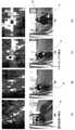
図6は、ガボールフィルタを用いた時空間解析の結果を示す図である。図6(A)は、減速する車両10を、バイクが追い抜くシーンを示す図である。図6(B)は、横軸を時間とし縦軸を反射レベルとするグラフである。図6(C)は、図6(A)に示すシーンを図6(B)のグラフに基づいて時空間解析した結果を示す図であり、縦軸は時間T、横軸は距離Pを表している。
図7は、画像データ中に存在する移動体までの距離Pと同一の距離の範囲を示す領域を含む画像Sの切り出しを行う処理の流れを示す図である。
図8は、サポートベクターマシン(SVM)空間によるトラッキングアルゴリズムを用いて移動体31を認識する様子を示す図である。
図9は、円弧状の線分Wにおける水平方向から移動体の角度を算出し、車両と移動体との相対位置を特定する手法を示す図である。
図10は、レーダ120及びカメラ121を、設置環境に対応させる手法を示す図である。
図11は、2次元マップの具体例を示す図である。
図12は、危険予測の具体例を示す図である。
図13は、図3の機能的構成を有する危険予測装置1が実行する一連の処理の流れを示すフローチャートである。Next, the functional configuration of the
FIG. 3 is a functional block diagram showing an example of the functional configuration for realizing the danger prediction process among the functional configurations of the
FIG. 4 shows a radar determined by a maximum distance (hereinafter referred to as “measurable distance”) L that can be measured by a
FIG. 5 is a flowchart showing a processing flow when performing spatiotemporal analysis using a Gabor filter.
FIG. 6 is a diagram showing the results of spatiotemporal analysis using a Gabor filter. FIG. 6A is a diagram showing a scene in which a motorcycle overtakes a decelerating
FIG. 7 is a diagram showing a flow of processing for cutting out an image S including a region showing a range of the same distance as the distance P to a moving body existing in the image data.
FIG. 8 is a diagram showing how the moving
FIG. 9 is a diagram showing a method of calculating the angle of a moving body from the horizontal direction in the arcuate line segment W and specifying the relative position between the vehicle and the moving body.
FIG. 10 is a diagram showing a method of adapting the
FIG. 11 is a diagram showing a specific example of a two-dimensional map.
FIG. 12 is a diagram showing a specific example of risk prediction.
FIG. 13 is a flowchart showing a flow of a series of processes executed by the
図3に示すように、危険予測装置1のCPU11(図2)において危険予測処理が実行される場合には、センサ部101と、撮像部102と、画像処理部103と、2次元マップ生成提示部104と、危険予測部105とが機能する。記憶部18(図2)の一領域には、距離DB401と、画像DB402と、自車DB403、時空間DB404とが設けられている。 As shown in FIG. 3, when the danger prediction process is executed in the CPU 11 (FIG. 2) of the
(センサ部)
センサ部101は、距離データ生成部111と、自車データ生成部112と、時空間解析部113とを含むように構成される。(Sensor part)
The
距離データ生成部111は、車両10の周囲の領域のうち、測定可能領域Mに存在する反射物21までの距離Pを計測し、この計測結果に基づいた情報(以下「距離データ」と呼ぶ)を生成する。距離データ生成部111により生成された距離データは、距離DB401に記憶されて管理される。距離データ生成部111が反射物21までの距離Pを測定する具体的な手法は特に限定されない。24GHz帯の周波数帯を利用したマイクロ波レーダ、60GHz帯及び76GHz帯の周波数帯を利用したミリ波レーダ、赤外線センサ等を用いることができる。なお、本実施形態では、マイクロ波レーダ(以下、単に「レーダ」と呼ぶ)120を採用し、周波数変調された連続波(FMCW/Frequency Modulated Continuous Wave radar)によって反射物21までの距離Pを計測して距離データを生成する。レーダ120を用いることにより、後述するカメラ121により撮像された画像に基づく画像データでは測定することができない奥行方向の正確な距離を測定することができる。 The distance
レーダ120の測定可能距離L及び測定可能角度Kは特に限定されないが、測定可能距離Lは25m以上であり、測定可能角度Kは45°以上であることが好ましい。例えば、測定可能距離Lを25mとし、測定可能角度Kを45°とするレーダ120を、車両10の右側先端部と、左側先端部と、後端中央部との3箇所に搭載した場合を想定する。この場合、車両10の全長Aが、道路運送車両法で定められた普通自動車の最大の長さと同じ12mであったとしても、例えば車両10の右側方部から右方向に5m、車両10の左側方部から左方向に5m、車両10の後端部から後方に13m(測定可能距離L(25m)-車両10の全長A(12m))で示される領域は、レーダ120の測定可能領域Mの一部に含まれることとなる。 The measurable distance L and the measurable angle K of the
レーダ120の感度は特に限定されないが、交通弱者70に含まれる歩行者(人体)の反射断面積が0.1m2以下であっても検知することができることが好ましい。レーダ120の感度がこのレベルに達していれば、形状が複雑であるがために有効な反射物として検出することが難しいとされている「人」を判別することが可能となる。The sensitivity of the
自車データ生成部112は、加速度センサで構成され、自車となる車両10の速度、加速度、及び移動する方向を算出し、算出結果に基づいた情報(以下「自車データ」と呼ぶ)を生成する。自車データ生成部112により生成された自車データは、自車DB403に記憶されて管理される。なお、自車データ生成部112による加速度の検出方式は特に限定されない。例えば、MEMS(Micro Electro Mechanical System)技術を用いたものであってもよい。 The own vehicle
時空間解析部113は、時空間解析を行う。時空間解析とは、時空間解析部113を構成する反射データ表示部311、第1識別部312、及び移動体データ生成部313により実行される一連の処理をいう。 The
反射データ表示部311は、距離データ生成部111により生成された距離データを時間軸の方向に蓄積させた情報(以下「時空間データ」と呼ぶ)を含む入力データに基づいて、反射物21の時空間上の距離変化を示す第1画像データを生成し、生成した第1画像データ上に、反射物21の反射データを表示させる。入力データには、自車データ生成部112により生成された自車データを含めることができる。 The reflection
第1識別部312は、第1画像データ上に表示された、1又は2以上の反射データUを、移動体を示す移動体反射データと、固定体を示す固定体反射データとにそれぞれ識別する。具体的には、第1識別部312は、空間フィルタリング処理により、1又は2以上の反射データUを、移動体31を示す移動体反射データと、固定体40を示す固定体反射データとにそれぞれ識別する。すなわち、第1識別部312では、図6(B)に示すように、横軸を時間Tとし縦軸を反射データUとするグラフBにおいて反射物21を示す曲線γを、横軸を時間Tとし縦軸を距離PとするグラフCにおいて時間Tの方向に複数並べていく処理が行われる。そして、グラフC上に並べられた複数の曲線γのそれぞれのピークとなる点を結ぶ処理が行われる。この処理により描画される線分の形状が、右上がりである場合には固定体反射データとして識別され、右下がりである場合には移動体反射データとして識別される。このようにして、1又は2以上の反射データUの中から、車両10に接近する移動体反射データαを識別表示させることができる。 The
移動体データ生成部313は、移動体反射データにより示される移動体31の、移動速度、加速度、及び移動方向を含む移動体データを生成する。 The mobile
時空間解析部113による時空間解析の結果、入力データから、電柱やガードレールなどの固定体反射データが除去され、相対速度が異なる移動体反射データのみが抽出される。これにより、例えば、図6(C)に示すように、複数の反射物21の中から、車両10に接近する移動体31(バイク)を示す移動体反射データが、右肩下がりの線分αで識別表示される。このとき、右肩上がりの線分βは、車両10から離反する固定体40(電柱)を示す移動体反射データによって示されたものである。なお、本実施形態では、固定体反射データと移動体反射データとの違いを色の違いで示すことにより、車両10に接近する移動体31を識別表示させている。ただし、これに限定されず、模様による識別や形状による識別等、あらゆる手法を用いて識別表示させてもよい。 As a result of the spatiotemporal analysis by the
複数の反射データUの中から、車両10に接近する移動体反射データを右肩下がりの線分αで識別表示させる空間フィルタリング処理の具体的な手法は特に限定されないが、本実施形態では、画像処理で用いられる空間フィルタリング処理の1つであるガボールフィルタを用いた処理が採用されている。ガボールフィルタは、特定の傾き(角度)を強調する性質を有する。本実施形態では、この性質を利用して、図5に示すように、傾き(角度)を示す値θが0°~180°となる範囲で、合計18段のガボールフィルタを用いている。すなわち、傾き(角度)θの値の範囲が10°毎に異なるガボールフィルタを、0°≦θ<10°とするフィルタ0から170°≦θ<180°とするフィルタ17まで、合計18段のガボールフィルタを用いた解析が行われる。このように、傾き(角度)がそれぞれ異なる18段のガボールフィルタを用いた時空間解析が行われることで、時空間データにおける線分の傾き(角度)を検出することができる。 The specific method of the spatial filtering process for identifying and displaying the moving object reflection data approaching the
(撮像部)
撮像部102は、カメラ121と、第2画像データ生成部122とで構成される。カメラ121は、車両10の周囲を撮像する。第2画像データ生成部122は、撮像された画像に基づく第2画像データを生成する。生成された第2画像データは、後述する画像処理部103による画像処理に用いられる。即ち、レーダ120のみでは移動体31の水平方向の位置を特定することができないので、後述する画像処理部103が、撮像部102で生成された第2画像データを用いて、移動体31の水平方向の位置の特定を行う。(Image pickup unit)
The
(第2識別部)
第2識別部103は、第2画像データ生成部122により生成された第2画像データと、移動体データ生成部313により生成された移動体データとを少なくとも含む情報に基づいて、第2画像データに含まれる移動体31のうち、車両10に接近する移動体31を識別する。なお、「少なくとも」とは、第2画像データに含まれる移動体31のうち、車両10に接近する移動体31を識別する際に用いられる情報に、移動体データ以外の情報が含まれていてもよいことを意味する。例えば、この情報に自車データが含まれていてもよい。
第2識別部103が、第2画像データに含まれる移動体31のうち、車両10に接近する移動体31を識別する具体的な手法は特に限定されない。例えば、機械学習の手法の1つであるSVM(Support Vector Machine)によってHOG(Histograms of Oriented Gradients)特徴量を学習することにより、画像データに含まれる移動体31を識別してもよい。これにより、識別表示された移動体31が交通弱者70であるか否かを判断することができる。(Second identification unit)
The
The specific method for the
また、第2識別部103は、識別した移動体31の水平方向の位置の特定と、移動体31の種類の特定とを行う。第2識別部103により特定される移動体31の種類には、人間が少なくとも含まれる。なお、「少なくとも」とは、移動体31の種類として人間以外が含まれてもよいことを意味する。つまり、移動体31には、車両10の周囲の領域内を移動し得るあらゆる物体が含まれてよい。例えば、人間が運転する自転車やオートバイや、犬や猫等の動物は、いずれも移動体31の一例である。 Further, the
ここで、移動体31は、サイズが同じである場合、カメラ121から遠い位置に存在する移動体31よりも、カメラ121から近い位置に存在する移動体31の方が画像データに大きく表示される。
このため、第2識別部103は、第2画像データ上の移動体31のスケールの調整を行う。具体的には、図7に示すように、第2識別部103は、第2画像データ中に存在する移動体31までの距離Pと同一の距離の範囲を示す領域を含む画像Sの切り出しを行い、切り出した画像Sを、想定される「人」のサイズに縮小させる。画像Sを縮小させる際の縮小スケールの段数n(nは1以上の整数値)は特に限定されないが、本実施形態では12段としている。これにより、カメラ121からの距離Pが異なる位置に存在する移動体31同士のスケールの調整を行うことができる。その結果、第2識別部103は、第2画像データ上の移動体31をより正確に識別することができる。Here, when the size of the moving
Therefore, the
第2画像データに、移動体31の全体が表示されない場合には、第2識別部103は、サポートベクターマシン(SVM)空間によるトラッキングアルゴリズムを用いて移動体31を識別する。例えば、図8は、移動体31が車両10に近寄ってくる様子を図8(A)~(D)の順で示している。移動体31と車両10との距離が5mであるとき(図8(A))、及び移動体31と車両10との距離が3mであるとき(図8(B))は、第2画像データに移動体31の全部が表示されている。このため、画像処理部103は、HOG特徴量をSVMによって学習することで第2画像データに含まれる移動体31を識別する。図8(A)及び(B)に示される、移動体31を囲む枠線Rは、HOG特徴量をSVMによる学習によって移動体31を識別表示する枠線である。一方、移動体31と車両10との距離が2mであるとき(図8(C))、及び移動体31と車両10との距離が1mであるとき(図8(D))は、移動体31の一部が、第2画像データに表示されていない(つまり移動体31が第2画像データから切れている)。このため、画像処理部103は、サポートベクターマシン(SVM)空間によるトラッキングアルゴリズムを用いることで、第2画像データに含まれる移動体31を識別する。図8(C)及び(D)に示される、移動体31を囲む枠線Vは、HOG特徴量をSVMによる学習によって移動体31を識別表示する枠線である。これにより、図8(A)~(D)に示すように、第2画像データに全体が表示されずに一部のみが表示されている移動体31についてもスムーズに認識することが可能となる。 When the entire moving
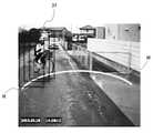
第2識別部103は、上述したように、第2画像データ中に存在する移動体31までの距離Pと同一の距離の範囲を示す領域を含んだ画像Sを切り出す処理を行うことにより、移動体31を識別する画像処理を行う範囲を限定することができる。すなわち、画像処理部103は、第2画像データのうち、画像処理の対象となる移動体31の大きさと、画像処理を行う位置とを限定した画像処理を行うことができる。これにより、画像処理に伴う計算量を減らすことができる。これにより、カメラ121の高解像度化に伴い増加傾向にある演算コストの低減化を図ることができる。 As described above, the
第2識別部103は、第2画像データ中に存在する移動体31を識別する画像処理を行う範囲を限定し、図9に示すように、第2画像データ中に存在する移動体31までの距離Pと同一の距離の範囲を示す領域を円弧状の線分Wで表示する。そして、線分Wに重畳して表示させた枠線Rの水平方向の向きに基づいて、移動体31の角度を算出する。これにより、自車(車両10)と移動体31との相対位置を特定することができる。 The
ところで、車両10の両側方にレーダ120及びカメラ121を搭載する場合、具体的な設置場所は、サイドミラーのアーム部分となる。しかしながら、サイドミラーのアーム部分は、車両10の種類によって大きく位置が異なる。例えば、車両10が大型トラックの場合、サイドミラーのアームの部分は、地面から約180cm程度の高さに配置される。また、車両10が中型トラックの場合、サイドミラーのアームの部分は、地面から約155cm程度の高さに配置される。また、車両10がトレーラの場合、サイドミラーのアームの部分は、地面から約200cm程度の高さに配置される。このため、車両10に搭載されるレーダ120及びカメラ121は、実際に設置する場所の地面からの高さや角度(以下「設置環境」と呼ぶ)の違いに対応可能できるようにする必要がある。 By the way, when the
画像処理部103は、レーダ120及びカメラ121の設置環境に応じて、測定可能距離Lを含む測定可能領域Mと、カメラ121の第2画像データ上の位置とを調整する。これにより、レーダ120及びカメラ121は、設置環境の違いに容易に対応させることができる。具体的には、画像処理部103は、図10(A)に示すように、アームに設置されたレーダ120及びカメラ121の設置環境(地面からの高さaや角度b)に応じて、第2画像データとして表示される映像の角度、反射物21までの距離P、反射物21を囲む枠線R及びVの縦の長さdや横の長さe等について、キャリブレーションを実行する。例えば、画像処理部103は、図10(B)に示すように、第2画像データに、車両10(すなわちレーダ120及びカメラ121)からの距離Pや車両10との相対的な角度を示すメッシュ状の線分Yを重畳的に表示させて、キャリブレーションを実行してもよい。これにより、後述する危険予測部105による危険予測が精度良く行われるための前提となる、第2画像データの正確性を担保することができる。 The
(2次元マップ生成提示部)
2次元マップ生成提示部104は、車両10を運転する運転者Dに対し、車両10と移動体31との位置関係を示す時空間パターンが表示された2次元マップFを生成し、生成された2次元マップFを運転者Dに提示する。2次元マップ生成提示部104により生成される2次元マップFは、図11に示すように、車両10の長手方向を表す縦軸と、車両10の長手方向に対し垂直方向(水平方向)の距離を表す横軸とからなる2次元のマップである。2次元マップFには、中心部に車両10を配置させた時空間パターンが表示されるとともに、交通弱者70(移動体31)の過去の移動履歴に基づいた移動軌跡が表示される。2次元マップFが車両10の運転席に搭載されたモニタ(出力部16)から出力されると、車両10を運転する運転者Dは、交通弱者70(移動体31)との間で交通事故が起きる可能性があることを、視覚を通じて直感的に認識することができる。
2次元マップFの具体的な構成は特に限定されないが、本実施形態に係る2次元マップFは、サイズを横(W)480pixel×縦(H)480pixel(ピクセル)とし、解像度を横(W)50mm×縦(H)50mm(0.104mm/pixel(ピクセル))とし、移動軌跡保持期間を4秒としている。これにより、2次元マップ生成提示部104は、車両10の死角領域Qで生じ得る車両10と交通弱者70(移動体31)との交通事故を未然に防ぐための情報を運転者Dに提供することができる。その結果、運転者Dは、交通弱者70(移動体31)との間で交通事故が起きる可能性があることを好適なタイミングで知ることができる。(2D map generation presentation unit)
The two-dimensional map
The specific configuration of the two-dimensional map F is not particularly limited, but the two-dimensional map F according to the present embodiment has a size of horizontal (W) 480 pixels × vertical (H) 480 pixels (pixels) and a resolution of horizontal (W). It is 50 mm × vertical (H) 50 mm (0.104 mm / pixel (pixel)), and the movement locus holding period is 4 seconds. As a result, the two-dimensional map
(危険予測部)
危険予測部105は、測定可能領域Mのうち、車両10と移動体31との間で交通事故が起きるリスクが高い領域を危険領域Xとして予め設定する。危険予測部105は、2次元マップFに表示される時空間パターンに基づいて、車両10の移動軌跡と、移動体31の移動軌跡とを評価して、移動体31が危険領域Xに進入するおそれがあるか否かを判断し、進入するおそれがあると判断した場合に、その旨を危険予測として運転者Dに提示する。例えば図12には、車両10と、車両10の測定可能領域Mに存在する移動体31(バイク)との相対速度が25km/hで、0.8秒後に移動体31(バイク)が危険領域Xに進入するおそれがある旨を危険予測する例が示されている。
この例において危険予測部105は、車両10の移動軌跡と、測定可能領域Mに存在する移動体31(バイク)の直近1秒間(1.0S)の移動軌跡とを評価し、移動体31(バイク)が、今から0.8秒後に5.6m離れた危険領域Xに進入するおそれがあると判断して、その旨を危険予測として運転者Dに提示する。運転者Dが警報を受けてハンドルを操作するまでの時間は、通常0.5秒程度とされている。このため、危険予測を提示するタイミングを、危険領域Xに進入する0.8秒前とすることにより、運転者Dとしてみれば、余裕を持った対応が可能となる。(Danger prediction department)
The
In this example, the
運転者Dに危険予測を提示する具体的な手法は特に限定されないが、本実施形態では、車両10の運転席に搭載されたモニタ(出力部16)と、エンジンの運転制御を電気的に制御する車両エンジンコントロールユニット(ECU)とに出力することにより危険予測を提示する。この場合、車両エンジンコントロールユニット(ECU)は、提示された危険予測に基づいて、車両制御、舵制御、警報の出力等を行ってもよい。 The specific method of presenting the danger prediction to the driver D is not particularly limited, but in the present embodiment, the monitor (output unit 16) mounted on the driver's seat of the
危険予測部105が、危険領域Xを予め設定する際の具体的手法は特に限定されない。例えば、時空間DB404に記憶されている時空間パターンに基づいて機械学習による回帰分析を行ってもよい。この場合、危険予測部105は、車両10と移動体31との間で交通事故が起きるリスクを数値化して、測定可能領域M内のあらゆる場所における危険度を複数段階(例えば危険度が高い順に高中低の3段階)で設定してもよい。 The specific method for setting the danger zone X in advance by the
次に、図13を参照して、図3の機能的構成を有する危険予測装置1が実行する一連の処理の流れについて説明する。
図13は、図3の危険予測装置1が実行する危険予測処理の流れを説明するフローチャートである。Next, with reference to FIG. 13, a series of processing flows executed by the
FIG. 13 is a flowchart illustrating a flow of the danger prediction process executed by the
図13に示すように、危険予測装置1では、次のような一連の処理が実行される。
ステップS1において、距離データ生成部111(レーダ120)は、車両10の周囲の領域のうち測定可能領域Mに存在する反射物21までの距離Pを計測し、この計測結果に基づいた距離データを生成する。As shown in FIG. 13, the
In step S1, the distance data generation unit 111 (radar 120) measures the distance P to the
ステップS2において、反射データ表示部311は、ステップS1で生成された距離データを時間軸の方向に蓄積させた時空間データを含む入力データに基づいて、反射物21の時空間上の距離変化を示す第1画像データを生成し、生成された第1画像データ上に、反射物21の反射データを表示させる。
ステップS3において、第1識別部312は、第1画像データ上に表示された、1又は2以上の反射データUを、移動体31を示す移動体反射データと、固定体を示す固定体反射データとにそれぞれ識別する。
ステップS4において、移動体データ生成部313は、移動体反射データにより示される移動体31の、移動速度、加速度、及び移動方向を含む移動体データを生成する。In step S2, the reflection
In step S3, the
In step S4, the mobile
ステップS5において、撮像部102は、車両の周囲を撮像する。
ステップS6において、第2画像データ生成部122は、撮像された画像に基づく第2画像データを生成する。In step S5, the
In step S6, the second image
ステップS7において、2次元マップ生成提示部104は、車両10を運転する運転者Dに対し、車両10と移動体31との位置関係を示す時空間パターンが表示された2次元マップFを生成し、生成された2次元マップFを運転者Dに提示する。
ステップS8において、危険予測部105は、測定可能領域Mのうち、車両10と移動体31との間で交通事故が起きるリスクが高い領域を危険領域Xとして予め設定する。
ステップS9において、危険予測部105は、時空間パターンに基づいて、車両10の移動軌跡と、移動体31の移動軌跡とを評価して、移動体31が危険領域Xに進入するおそれがあるか否かを判断し、進入するおそれがあると判断した場合に、その旨を危険予測として運転者Dに提示する。これにより処理は終了する。In step S7, the two-dimensional map
In step S8, the
In step S9, the
以上のような一連の処理が実行されることにより、車両10の運転者Dの死角領域Qにおいて、移動体31と固定体40とを的確に判別し、移動体31の急激な速度変化に的確に対応し、また、「人」を的確に判別する。その結果、車両10と交通弱者70(移動体31)との交通事故を未然に防ぐための情報を運転者Dに提供することができる。 By executing the series of processes as described above, the moving
以上、本発明の一実施形態について説明したが、本発明は、上述の実施形態に限定されるものではなく、本発明の目的を達成できる範囲での変形、改良等は本発明に含まれるものである。 Although one embodiment of the present invention has been described above, the present invention is not limited to the above-described embodiment, and modifications, improvements, etc. within the range in which the object of the present invention can be achieved are included in the present invention. Is.
例えば、本実施形態における車両10は、トラック等の大型の車両としているが、これは例示であり、普通車等であってもよい。 For example, the
また、図2に示す各ハードウェア構成は、本発明の目的を達成するための例示に過ぎず、特に限定されない。 Further, each hardware configuration shown in FIG. 2 is merely an example for achieving the object of the present invention, and is not particularly limited.
また、図3に示す機能ブロック図は、例示に過ぎず、特に限定されない。即ち、上述した一連の処理を全体として実行出来る機能が危険予測装置に備えられていれば足り、この機能を実現するためにどのような機能ブロックを用いるのかは、特に図3の例に限定されない。 Further, the functional block diagram shown in FIG. 3 is merely an example and is not particularly limited. That is, it suffices if the risk prediction device is provided with a function capable of executing the above-mentioned series of processes as a whole, and what kind of functional block is used to realize this function is not particularly limited to the example of FIG. ..
また、機能ブロックの存在場所も、図3に示す場所に限定されず、任意でよい。
そして、1つの機能ブロックは、ハードウェア単体で構成しても良いし、ソフトウェア単体との組み合わせで構成しても良い。Further, the location of the functional block is not limited to the location shown in FIG. 3, and may be arbitrary.
Then, one functional block may be configured by a single piece of hardware or by a combination of a single piece of software.
各機能ブロックの処理をソフトウェアにより実行させる場合には、そのソフトウェアを構成するプログラムが、コンピュータ等にネットワークや記録媒体からインストールされる。
コンピュータは、専用のハードウェアに組み込まれているコンピュータであってもよい。また、コンピュータは、各種のプログラムをインストールすることで、各種の機能を実行することが可能なコンピュータ、例えばサーバの他汎用のスマートフォンやパーソナルコンピュータであってもよい。When the processing of each functional block is executed by software, the programs constituting the software are installed in a computer or the like from a network or a recording medium.
The computer may be a computer embedded in dedicated hardware. Further, the computer may be a computer capable of executing various functions by installing various programs, for example, a general-purpose smartphone or a personal computer in addition to a server.
このようなプログラムを含む記録媒体は、各ユーザにプログラムを提供するために装置本体とは別に配布される、リムーバブルメディアにより構成されるだけではなく、装置本体に予め組み込まれた状態で各ユーザに提供される記録媒体等で構成される。 The recording medium containing such a program is not only composed of removable media, which is distributed separately from the main body of the device to provide the program to each user, but also is preliminarily incorporated in the main body of the device to each user. It is composed of the provided recording media and the like.
なお、本明細書において、記録媒体に記録されるプログラムを記述するステップは、その順序に添って時系列的に行われる処理はもちろん、必ずしも時系列的に処理されなくとも、並列的或いは個別に実行される処理をも含むものである。 In this specification, the steps for describing a program to be recorded on a recording medium are not only processed in chronological order but also in parallel or individually, even if they are not necessarily processed in chronological order. It also includes the processing to be executed.
以上まとめると、本発明が適用される危険予測装置(例えば図3の危険予測装置1)は、次のような構成を取れば足り、各種各様な実施形態を取ることができる。
即ち、本発明が適用される危険予測装置は、
車両(例えば図1の車両10)に搭載される危険予測装置であって、
前記車両の周囲の領域のうち測定可能領域(例えば図4の測定可能領域M)に存在する反射物(例えば図10の反射物21)までの距離(例えば図10の距離P)を計測し、当該計測の結果に基づいた距離データを生成する距離データ生成手段(例えば図3の距離データ生成部111)と、
前記距離データを時間軸の方向に蓄積させた時空間データを含む入力データに基づいて、前記反射物の時空間上の距離変化を示す第1画像データを生成し、生成された前記第1画像データ上に、前記反射物の反射データを表示させる反射データ表示手段(例えば図3の反射データ表示部311)と、
前記第1画像データ上に表示された、1又は2以上の前記反射データを、移動体を示す移動体反射データと、固定体を示す固定体反射データとにそれぞれ識別する第1識別手段(例えば図3の第1識別部312)と、
前記移動体反射データにより示される前記移動体の、移動速度、加速度、及び移動方向を含む移動体データを生成する移動体データ生成手段(例えば図3の移動体データ生成部313)と、
前記車両の周囲を撮像する撮像手段(例えば図3の撮像部102)と、
撮像された画像に基づく第2画像データを生成する第2画像データ生成手段(例えば図3の第2画像データ生成部122)と、
生成された前記第2画像データと、前記移動体データとを少なくとも含む情報に基づいて、前記第2画像データに含まれる前記移動体のうち、前記車両に接近する移動体を識別する第2識別手段(例えば図3の第2識別部103)と、
を備える。
これにより、車両(例えば図1の車両10)の運転者(例えば図1の運転者D)の死角となる後方部及び側方部において、接近物(例えば移動体31)と離反物(例えば固定体40)とを的確に判別することが可能となる。In summary, the risk prediction device to which the present invention is applied (for example, the
That is, the risk prediction device to which the present invention is applied is
A danger prediction device mounted on a vehicle (for example, the
The distance (for example, the distance P in FIG. 10) to the reflector (for example, the
Based on the input data including the spatiotemporal data obtained by accumulating the distance data in the direction of the time axis, the first image data showing the spatiotemporal distance change of the reflector is generated, and the generated first image. Reflection data display means (for example, reflection
A first identification means (for example,) for discriminating one or more of the reflection data displayed on the first image data into a moving body reflection data indicating a moving body and a fixed body reflection data indicating a fixed body, respectively. The first identification unit 312) in FIG. 3 and
A moving body data generation means (for example, a moving body
An imaging means (for example, an
A second image data generation means (for example, the second image
A second identification that identifies a moving body approaching the vehicle among the moving bodies included in the second image data based on information including at least the generated second image data and the moving body data. Means (for example, the
To prepare for.
As a result, the approaching object (for example, the moving body 31) and the detached object (for example, fixed) are in the rear portion and the side portion which are blind spots of the driver (for example, the driver D in FIG. 1) of the vehicle (for example, the
また、本発明の一態様の危険予測装置において、前記第1識別手段は、空間フィルタリング処理により、前記1又は2以上の前記反射データを、前記移動体を示す移動体反射データと、前記固定体反射データとにそれぞれ識別することができる、ことが好ましい。
この発明によれば、1又は2以上の反射データの中から、車両に接近する移動体反射データを識別表示させることができる。Further, in the danger prediction device of one aspect of the present invention, the first identification means performs spatial filtering processing to obtain the one or two or more of the reflection data, the mobile reflection data indicating the moving body, and the fixed body. It is preferable that they can be distinguished from the reflection data.
According to the present invention, it is possible to identify and display the moving object reflection data approaching the vehicle from one or more reflection data.
また、本発明の一態様の危険予測装置において、空間フィルタリング処理が、ガボールフィルタを複数段用いた処理である、ことが好ましい。
この発明によれば、時空間データにおける線分の傾き(角度)を検出することができる。Further, in the risk prediction device of one aspect of the present invention, it is preferable that the spatial filtering process is a process using a plurality of stages of Gabor filters.
According to the present invention, the slope (angle) of a line segment in spatiotemporal data can be detected.
また、本発明の一態様の危険予測装置において、前記第2識別手段は、さらに、前記移動体の水平方向の位置の特定を行う、ことが好ましい。
また、本発明の一態様の危険予測装置において、前記第2識別手段は、さらに、識別した前記移動体の種類を特定する、ことが好ましい。
この発明によれば、危険予測が精度良く行われるための前提となる第2画像データの正確性を担保することができる。Further, in the danger prediction device of one aspect of the present invention, it is preferable that the second identification means further identifies the horizontal position of the moving body.
Further, in the danger prediction device of one aspect of the present invention, it is preferable that the second identification means further specifies the type of the identified moving object.
According to the present invention, it is possible to ensure the accuracy of the second image data, which is a premise for the risk prediction to be performed accurately.
また、本発明の一態様の危険予測装置において、前記種類には、人間が少なくとも含まれる、ことが好ましい。
この発明によれば、接近物(移動体31)の急激な速度変化に的確に対応し、「人」を的確に判別することが可能となる。Further, in the risk prediction device of one aspect of the present invention, it is preferable that the type includes at least a human being.
According to the present invention, it is possible to accurately respond to a sudden change in speed of an approaching object (moving body 31) and accurately identify a "person".
また、本発明の一態様の危険予測装置において、
前記測定可能領域のうち、前記車両と前記移動体との間で交通事故が起きるリスクが高い領域を危険領域として予め設定する危険領域設定手段と、
前記時空間パターンに基づいて、前記車両の移動軌跡と、前記移動体の移動軌跡とを評価して、前記移動体が前記危険領域に進入するおそれがあるか否かを判断し、進入するおそれがあると判断した場合に、その旨を危険予測として前記運転者に提示する危険予測手段と、
をさらに備える、ことが好ましい。
この発明によれば、車両10と交通弱者70(移動体31)との交通事故を未然に防ぐための情報を運転者Dに提供することができる。Further, in the risk prediction device of one aspect of the present invention,
Among the measurable areas, a danger area setting means for presetting a area where there is a high risk of a traffic accident between the vehicle and the moving body as a danger area, and
Based on the space-time pattern, the movement locus of the vehicle and the movement locus of the moving body are evaluated to determine whether or not the moving body may enter the dangerous area, and the moving body may enter. When it is determined that there is, a danger prediction means that presents that fact to the driver as a danger prediction, and
It is preferable to further provide.
According to the present invention, it is possible to provide the driver D with information for preventing a traffic accident between the
また、本発明の一態様の危険予測装置において、前記第2識別手段は、前記距離データ生成手段及び前記撮像手段の設置環境に応じて、前記測定可能領域と、前記第2画像データとを調整する、ことが好ましい。
この発明によれば、危険予測が精度良く行われるための前提となる、第2画像データの正確性を担保することができる。Further, in the danger prediction device of one aspect of the present invention, the second identification means adjusts the measurable area and the second image data according to the installation environment of the distance data generation means and the image pickup means. It is preferable to do.
According to the present invention, it is possible to ensure the accuracy of the second image data, which is a premise for the risk prediction to be performed accurately.
1:危険予測装置
10:車両
11:CPU
12:ROM
13:RAM
14:バス
15:入出力インターフェース
16:表示部
17:入力部
18:記憶部
19:通信部
20:ドライブ
21:反射物
30:リムーバブルメディア
31:移動体
40:固定体
70:交通弱者
101:センサ部
102:撮像部
103:第2識別部
104:2次元マップ生成部
105:危険予測部
111:距離データ生成部
112:自車データ生成部
113:時空間解析部
120:レーダ
121:カメラ
122:第2画像データ生成部
311:反射データ表示部
312:第1識別部
313:移動体データ生成部
401:距離DB
402:画像DB
403:自車DB
404:時空間DB
A:車両の全長
B:グラフ
C:グラフ
D:運転者
F:2次元マップ
K:測定可能角度
L:測定可能距離
M:測定可能領域
n:段数
P:距離
Q:死角領域
R:枠線
S:画像
T:時間
U:反射レベル
V:枠線
W:線分
X:危険領域
Y:線分
α:線分
β:線分
γ:曲線
1: Danger prediction device 10: Vehicle 11: CPU
12: ROM
13: RAM
14: Bus 15: Input / output interface 16: Display 17: Input 18: Storage 19: Communication 20: Drive 21: Reflector 30: Removable media 31: Mobile 40: Fixed 70: Traffic vulnerable 101: Sensor Unit 102: Imaging unit 103: Second identification unit 104: Two-dimensional map generation unit 105: Danger prediction unit 111: Distance data generation unit 112: Own vehicle data generation unit 113: Spatio-temporal analysis unit 120: Radar 121: Camera 122: 2nd image data generation unit 311: Reflection data display unit 312: 1st identification unit 313: Mobile data generation unit 401: Distance DB
402: Image DB
403: Own vehicle DB
404: Space-time DB
A: Total length of vehicle B: Graph C: Graph D: Driver F: Two-dimensional map K: Measurable angle L: Measurable distance M: Measurable area n: Number of stages P: Distance Q: Blind spot area R: Frame line S : Image T: Time U: Reflection level V: Frame line W: Line segment X: Danger area Y: Line segment α: Line segment β: Line segment γ: Curve
Claims (11)
Translated fromJapanese前記車両の周囲の領域のうち測定可能領域に存在する反射物までの距離を計測し、当該計測の結果に基づいた距離データを生成する距離データ生成手段と、
生成された前記距離データを時間軸の方向に蓄積させた時空間データを含む入力データに基づいて、前記反射物の時空間上の距離変化を示す第1画像データを生成し、生成した第1画像データ上に、前記反射物の反射データを表示させる反射データ表示手段と、
前記第1画像データ上に表示された、1又は2以上の前記反射データを、移動体を示す移動体反射データと、固定体を示す固定体反射データとにそれぞれ識別する第1識別手段と、
前記移動体反射データにより示される前記移動体の、移動速度、加速度、及び移動方向を含む移動体データを生成する移動体データ生成手段と、
前記車両の周囲を撮像する撮像手段と、
撮像された画像に基づく第2画像データを生成する第2画像データ生成手段と、
生成された前記第2画像データと、前記移動体データとを少なくとも含む情報に基づいて、前記第2画像データに含まれる前記移動体のうち、前記車両に接近する移動体を識別する第2識別手段と、
を備える危険予測装置。It is a danger prediction device installed in a vehicle.
A distance data generation means that measures the distance to a reflective object existing in a measurable area of the area around the vehicle and generates distance data based on the measurement result.
Based on the input data including the spatiotemporal data obtained by accumulating the generated distance data in the direction of the time axis, the first image data showing the spatiotemporal distance change of the reflective object is generated, and the generated first image data is generated. A reflection data display means for displaying the reflection data of the reflective object on the image data,
A first identification means for discriminating one or more of the reflection data displayed on the first image data into a moving body reflection data indicating a moving body and a fixed body reflection data indicating a fixed body, respectively.
A mobile data generation means for generating mobile data including a moving speed, an acceleration, and a moving direction of the moving body indicated by the moving body reflection data.
An imaging means that images the surroundings of the vehicle, and
A second image data generation means for generating a second image data based on the captured image, and a second image data generation means.
A second identification that identifies a moving body approaching the vehicle among the moving bodies included in the second image data based on information including at least the generated second image data and the moving body data. Means and
A danger predictor equipped with.
空間フィルタリング処理により、前記1又は2以上の前記反射データを、前記移動体を示す移動体反射データと、前記固定体を示す固定体反射データとにそれぞれ識別する、
請求項1に記載の危険予測装置。The first identification means is
By the spatial filtering process, the one or two or more reflection data are discriminated into the moving body reflection data indicating the moving body and the fixed body reflection data indicating the fixed body, respectively.
The risk prediction device according to claim 1.
請求項2に記載の危険予測装置。The spatial filtering process is a process using a plurality of stages of Gabor filters.
The risk prediction device according to claim 2.
識別した前記移動体の水平方向の位置の特定を行う、
請求項1~3のうちいずれか1項に記載の危険予測装置。The second identification means further
Identify the horizontal position of the identified moving object,
The risk prediction device according to any one of claims 1 to 3.
識別した前記移動体の種類を特定する、
請求項1~4のうちいずれか1項に記載の危険予測装置。The second identification means further
Identify the type of identified mobile body,
The risk prediction device according to any one of claims 1 to 4.
請求項5に記載の危険予測装置。The types include at least humans,
The risk prediction device according to claim 5.
請求項1~6のうちいずれか1項に記載の危険予測装置。A two-dimensional map generation presentation means that generates a two-dimensional map displaying a spatio-temporal pattern showing the positional relationship between the vehicle and the moving body and presents the two-dimensional map to the driver who drives the vehicle. Further prepare
The risk prediction device according to any one of claims 1 to 6.
前記時空間パターンに基づいて、前記車両の移動軌跡と、前記移動体の移動軌跡とを評価して、前記移動体が前記危険領域に進入するおそれがあるか否かを判断し、進入するおそれがあると判断した場合に、その旨を危険予測として前記運転者に提示する危険予測手段と、
をさらに備える、
請求項7に記載の危険予測装置。Among the measurable areas, a danger area setting means for presetting a area where there is a high risk of a traffic accident between the vehicle and the moving body as a danger area, and
Based on the space-time pattern, the movement locus of the vehicle and the movement locus of the moving body are evaluated to determine whether or not the moving body may enter the dangerous area, and the moving body may enter. When it is determined that there is, a danger prediction means that presents that fact to the driver as a danger prediction, and
Further prepare,
The risk prediction device according to claim 7.
請求項1~8のうちいずれか1項に記載の危険予測装置。The second identification means adjusts the measurable area and the second image data according to the installation environment of the distance data generation means and the image pickup means.
The risk prediction device according to any one of claims 1 to 8.
前記車両の周囲の領域のうち測定可能領域に存在する反射物までの距離を計測し、当該計測の結果に基づいた距離データを生成する距離データ生成ステップと、
前記距離データを時間軸の方向に蓄積させた時空間データを含む入力データに基づいて、前記反射物の時空間上の距離変化を示す第1画像データを生成し、生成された前記第1画像データ上に、前記反射物の反射データを表示させる反射データ表示ステップと、
前記第1画像データ上に表示された、1又は2以上の前記反射データを、移動体を示す移動体反射データと、固定体を示す固定体反射データとにそれぞれ識別する第1識別ステップと、
前記移動体反射データにより示される前記移動体の、移動速度、加速度、及び移動方向を含む移動体データを生成する移動体データ生成ステップと、
前記車両の周囲を撮像する撮像ステップと、
撮像された画像に基づく第2画像データを生成する第2画像データ生成ステップと、
生成された前記第2画像データと、前記移動体データとを少なくとも含む情報に基づいて、前記第2画像データに含まれる前記移動体のうち、前記車両に接近する移動体を識別する第2識別ステップと、
を含む危険予測方法。It is a method used for risk prediction in vehicles.
A distance data generation step that measures the distance to a reflective object existing in the measurable area of the area around the vehicle and generates distance data based on the measurement result.
Based on the input data including the spatiotemporal data obtained by accumulating the distance data in the direction of the time axis, the first image data showing the spatiotemporal distance change of the reflector is generated, and the generated first image. A reflection data display step for displaying the reflection data of the reflective object on the data,
A first identification step for discriminating one or more of the reflection data displayed on the first image data into a moving body reflection data indicating a moving body and a fixed body reflection data indicating a fixed body, respectively.
A moving body data generation step for generating moving body data including a moving speed, an acceleration, and a moving direction of the moving body indicated by the moving body reflection data.
An imaging step that images the surroundings of the vehicle, and
A second image data generation step that generates second image data based on the captured image, and
A second identification that identifies a moving body approaching the vehicle among the moving bodies included in the second image data based on information including at least the generated second image data and the moving body data. Steps and
Risk prediction methods including.
車両の周囲の領域のうち測定可能領域に存在する反射物までの距離を計測し、当該計測の結果に基づいた距離データを生成する距離データ生成ステップと、
前記距離データを時間軸の方向に蓄積させた時空間データを含む入力データに基づいて、前記反射物の時空間上の距離変化を示す第1画像データを生成し、生成された前記第1画像データ上に、前記反射物の反射データを表示させる反射データ表示ステップと、
前記第1画像データ上に表示された、1又は2以上の前記反射データを、移動体を示す移動体反射データと、固定体を示す固定体反射データとにそれぞれ識別する第1識別ステップと、
前記移動体反射データにより示される前記移動体の、移動速度、加速度、及び移動方向を含む移動体データを生成する移動体データ生成ステップと、
前記車両の周囲を撮像する撮像ステップと、
撮像された画像に基づく第2画像データを生成する第2画像データ生成ステップと、
生成された前記第2画像データと、前記移動体データとを少なくとも含む情報に基づいて、前記第2画像データに含まれる前記移動体のうち、前記車両に接近する移動体を識別する第2識別ステップと、
を含む制御処理を実行させるプログラム。To the computer that controls the danger predictor,
A distance data generation step that measures the distance to a reflective object existing in the measurable area of the area around the vehicle and generates distance data based on the measurement result.
Based on the input data including the spatiotemporal data obtained by accumulating the distance data in the direction of the time axis, the first image data showing the spatiotemporal distance change of the reflector is generated, and the generated first image. A reflection data display step for displaying the reflection data of the reflective object on the data, and
A first identification step for discriminating one or more of the reflection data displayed on the first image data into a moving body reflection data indicating a moving body and a fixed body reflection data indicating a fixed body, respectively.
A moving body data generation step for generating moving body data including a moving speed, an acceleration, and a moving direction of the moving body indicated by the moving body reflection data.
An imaging step that images the surroundings of the vehicle, and
A second image data generation step that generates second image data based on the captured image, and
A second identification that identifies a moving body approaching the vehicle among the moving bodies included in the second image data based on information including at least the generated second image data and the moving body data. Steps and
A program that executes control processing including.
Priority Applications (1)
| Application Number | Priority Date | Filing Date | Title |
|---|---|---|---|
| JP2018066045AJP7033308B2 (en) | 2018-03-29 | 2018-03-29 | Hazard Predictors, Hazard Prediction Methods, and Programs |
Applications Claiming Priority (1)
| Application Number | Priority Date | Filing Date | Title |
|---|---|---|---|
| JP2018066045AJP7033308B2 (en) | 2018-03-29 | 2018-03-29 | Hazard Predictors, Hazard Prediction Methods, and Programs |
Publications (2)
| Publication Number | Publication Date |
|---|---|
| JP2019175372A JP2019175372A (en) | 2019-10-10 |
| JP7033308B2true JP7033308B2 (en) | 2022-03-10 |
Family
ID=68166956
Family Applications (1)
| Application Number | Title | Priority Date | Filing Date |
|---|---|---|---|
| JP2018066045AActiveJP7033308B2 (en) | 2018-03-29 | 2018-03-29 | Hazard Predictors, Hazard Prediction Methods, and Programs |
Country Status (1)
| Country | Link |
|---|---|
| JP (1) | JP7033308B2 (en) |
Families Citing this family (2)
| Publication number | Priority date | Publication date | Assignee | Title |
|---|---|---|---|---|
| CN114787892B (en)* | 2020-02-27 | 2025-01-14 | 松下知识产权经营株式会社 | Control system and control method |
| CN113392723A (en)* | 2021-05-25 | 2021-09-14 | 珠海市亿点科技有限公司 | Unmanned aerial vehicle forced landing area screening method, device and equipment based on artificial intelligence |
Citations (6)
| Publication number | Priority date | Publication date | Assignee | Title |
|---|---|---|---|---|
| JP2004361155A (en) | 2003-06-03 | 2004-12-24 | Fujitsu Ten Ltd | Target object determination device, target object determination device, and determination auxiliary device |
| JP2009217495A (en) | 2008-03-10 | 2009-09-24 | Toyota Central R&D Labs Inc | Hazard warning device |
| JP2009230390A (en) | 2008-03-21 | 2009-10-08 | Denso Corp | Recognition system |
| JP2011238161A (en) | 2010-05-13 | 2011-11-24 | Yupiteru Corp | Alarm device |
| JP2012194784A (en) | 2011-03-16 | 2012-10-11 | Fujitsu Ltd | Mobile body information measuring device and mobile body information measuring method |
| WO2014033957A1 (en) | 2012-09-03 | 2014-03-06 | トヨタ自動車株式会社 | Collision determination device and collision determination method |
- 2018
- 2018-03-29JPJP2018066045Apatent/JP7033308B2/enactiveActive
Patent Citations (7)
| Publication number | Priority date | Publication date | Assignee | Title |
|---|---|---|---|---|
| JP2004361155A (en) | 2003-06-03 | 2004-12-24 | Fujitsu Ten Ltd | Target object determination device, target object determination device, and determination auxiliary device |
| JP2009217495A (en) | 2008-03-10 | 2009-09-24 | Toyota Central R&D Labs Inc | Hazard warning device |
| JP2009230390A (en) | 2008-03-21 | 2009-10-08 | Denso Corp | Recognition system |
| JP2011238161A (en) | 2010-05-13 | 2011-11-24 | Yupiteru Corp | Alarm device |
| JP2012194784A (en) | 2011-03-16 | 2012-10-11 | Fujitsu Ltd | Mobile body information measuring device and mobile body information measuring method |
| WO2014033957A1 (en) | 2012-09-03 | 2014-03-06 | トヨタ自動車株式会社 | Collision determination device and collision determination method |
| US20150234044A1 (en) | 2012-09-03 | 2015-08-20 | Toyota Jidosha Kabushiki Kaisha | Collision determination device and collision determination method |
Also Published As
| Publication number | Publication date |
|---|---|
| JP2019175372A (en) | 2019-10-10 |
Similar Documents
| Publication | Publication Date | Title |
|---|---|---|
| JP7397807B2 (en) | Rider assistance system and method | |
| US11798290B2 (en) | Obstacle detection and notification for motorcycles | |
| EP3298604B1 (en) | Safety system for a vehicle to detect and warn of a potential collision | |
| CN104251993B (en) | Vehicle surroundings monitoring device | |
| RU2724935C1 (en) | METHOD AND SYSTEM OF NOTIFICATION OF A LOAD CAR DRIVER | |
| JP5172366B2 (en) | Vehicle driving support device | |
| EP2896029B1 (en) | Backward movement indicator apparatus for a vehicle | |
| JP4415856B2 (en) | Method for detecting the forward perimeter of a road vehicle by a perimeter sensing system | |
| KR20120055458A (en) | Method of capturing the surroundings of a vehicle | |
| US10846833B2 (en) | System and method for visibility enhancement | |
| KR20180065527A (en) | Vehicle side-rear warning device and method using the same | |
| CN112149560B (en) | Lane departure detection method | |
| JP4751894B2 (en) | A system to detect obstacles in front of a car | |
| JP5003473B2 (en) | Warning device | |
| JP7033308B2 (en) | Hazard Predictors, Hazard Prediction Methods, and Programs | |
| Rammohan et al. | Automotive Collision Avoidance System: A Review | |
| KR20180039838A (en) | Alarm controlling device of vehicle and method thereof | |
| CN219302678U (en) | Obstacle avoidance device for vehicle and obstacle avoidance equipment for vehicle | |
| US20250058712A1 (en) | Augmented vehicle blind spot detection with transparent trailer | |
| JP2025134650A (en) | Traffic warning system, computer readable medium, and method of operation thereof | |
| CN120108223A (en) | Blind spot warning method, device, vehicle and storage medium based on surround view system | |
| KR101683677B1 (en) | Apparatus and method for controlling around view of vehicle | |
| JP2022133849A (en) | Display control device, display control method and program | |
| JP2022133850A (en) | Display control device, display control method and program | |
| CN119636787A (en) | Vehicle control method, device, storage medium and program product |
Legal Events
| Date | Code | Title | Description |
|---|---|---|---|
| A521 | Request for written amendment filed | Free format text:JAPANESE INTERMEDIATE CODE: A523 Effective date:20180424 | |
| A621 | Written request for application examination | Free format text:JAPANESE INTERMEDIATE CODE: A621 Effective date:20210210 | |
| A711 | Notification of change in applicant | Free format text:JAPANESE INTERMEDIATE CODE: A711 Effective date:20210210 | |
| A521 | Request for written amendment filed | Free format text:JAPANESE INTERMEDIATE CODE: A821 Effective date:20210210 | |
| A977 | Report on retrieval | Free format text:JAPANESE INTERMEDIATE CODE: A971007 Effective date:20220117 | |
| TRDD | Decision of grant or rejection written | ||
| A01 | Written decision to grant a patent or to grant a registration (utility model) | Free format text:JAPANESE INTERMEDIATE CODE: A01 Effective date:20220125 | |
| A61 | First payment of annual fees (during grant procedure) | Free format text:JAPANESE INTERMEDIATE CODE: A61 Effective date:20220218 | |
| R150 | Certificate of patent or registration of utility model | Ref document number:7033308 Country of ref document:JP Free format text:JAPANESE INTERMEDIATE CODE: R150 | |
| R250 | Receipt of annual fees | Free format text:JAPANESE INTERMEDIATE CODE: R250 |