JP7031777B1 - Electric unit and mounting method - Google Patents
Electric unit and mounting methodDownload PDFInfo
- Publication number
- JP7031777B1 JP7031777B1JP2021073412AJP2021073412AJP7031777B1JP 7031777 B1JP7031777 B1JP 7031777B1JP 2021073412 AJP2021073412 AJP 2021073412AJP 2021073412 AJP2021073412 AJP 2021073412AJP 7031777 B1JP7031777 B1JP 7031777B1
- Authority
- JP
- Japan
- Prior art keywords
- engaging
- recess
- slit
- shaft portion
- ecu
- Prior art date
- Legal status (The legal status is an assumption and is not a legal conclusion. Google has not performed a legal analysis and makes no representation as to the accuracy of the status listed.)
- Active
Links
Images


Classifications
- H—ELECTRICITY
- H01—ELECTRIC ELEMENTS
- H01R—ELECTRICALLY-CONDUCTIVE CONNECTIONS; STRUCTURAL ASSOCIATIONS OF A PLURALITY OF MUTUALLY-INSULATED ELECTRICAL CONNECTING ELEMENTS; COUPLING DEVICES; CURRENT COLLECTORS
- H01R13/00—Details of coupling devices of the kinds covered by groups H01R12/70 or H01R24/00 - H01R33/00
- H01R13/62—Means for facilitating engagement or disengagement of coupling parts or for holding them in engagement
- H01R13/629—Additional means for facilitating engagement or disengagement of coupling parts, e.g. aligning or guiding means, levers, gas pressure electrical locking indicators, manufacturing tolerances
- H01R13/631—Additional means for facilitating engagement or disengagement of coupling parts, e.g. aligning or guiding means, levers, gas pressure electrical locking indicators, manufacturing tolerances for engagement only
- H—ELECTRICITY
- H05—ELECTRIC TECHNIQUES NOT OTHERWISE PROVIDED FOR
- H05K—PRINTED CIRCUITS; CASINGS OR CONSTRUCTIONAL DETAILS OF ELECTRIC APPARATUS; MANUFACTURE OF ASSEMBLAGES OF ELECTRICAL COMPONENTS
- H05K5/00—Casings, cabinets or drawers for electric apparatus
- H05K5/0026—Casings, cabinets or drawers for electric apparatus provided with connectors and printed circuit boards [PCB], e.g. automotive electronic control units
- H05K5/0065—Casings, cabinets or drawers for electric apparatus provided with connectors and printed circuit boards [PCB], e.g. automotive electronic control units wherein modules are associated together, e.g. electromechanical assemblies, modular structures
- H—ELECTRICITY
- H01—ELECTRIC ELEMENTS
- H01R—ELECTRICALLY-CONDUCTIVE CONNECTIONS; STRUCTURAL ASSOCIATIONS OF A PLURALITY OF MUTUALLY-INSULATED ELECTRICAL CONNECTING ELEMENTS; COUPLING DEVICES; CURRENT COLLECTORS
- H01R13/00—Details of coupling devices of the kinds covered by groups H01R12/70 or H01R24/00 - H01R33/00
- H01R13/62—Means for facilitating engagement or disengagement of coupling parts or for holding them in engagement
- H01R13/627—Snap or like fastening
- H01R13/6271—Latching means integral with the housing
- H01R13/6272—Latching means integral with the housing comprising a single latching arm
- H—ELECTRICITY
- H01—ELECTRIC ELEMENTS
- H01R—ELECTRICALLY-CONDUCTIVE CONNECTIONS; STRUCTURAL ASSOCIATIONS OF A PLURALITY OF MUTUALLY-INSULATED ELECTRICAL CONNECTING ELEMENTS; COUPLING DEVICES; CURRENT COLLECTORS
- H01R33/00—Coupling devices specially adapted for supporting apparatus and having one part acting as a holder providing support and electrical connection via a counterpart which is structurally associated with the apparatus, e.g. lamp holders; Separate parts thereof
- H01R33/94—Holders formed as intermediate parts for linking a counter-part to a coupling part
- H—ELECTRICITY
- H01—ELECTRIC ELEMENTS
- H01R—ELECTRICALLY-CONDUCTIVE CONNECTIONS; STRUCTURAL ASSOCIATIONS OF A PLURALITY OF MUTUALLY-INSULATED ELECTRICAL CONNECTING ELEMENTS; COUPLING DEVICES; CURRENT COLLECTORS
- H01R43/00—Apparatus or processes specially adapted for manufacturing, assembling, maintaining, or repairing of line connectors or current collectors or for joining electric conductors
- H01R43/26—Apparatus or processes specially adapted for manufacturing, assembling, maintaining, or repairing of line connectors or current collectors or for joining electric conductors for engaging or disengaging the two parts of a coupling device
- H—ELECTRICITY
- H02—GENERATION; CONVERSION OR DISTRIBUTION OF ELECTRIC POWER
- H02G—INSTALLATION OF ELECTRIC CABLES OR LINES, OR OF COMBINED OPTICAL AND ELECTRIC CABLES OR LINES
- H02G3/00—Installations of electric cables or lines or protective tubing therefor in or on buildings, equivalent structures or vehicles
- H02G3/02—Details
- H02G3/08—Distribution boxes; Connection or junction boxes
- H02G3/14—Fastening of cover or lid to box
- H—ELECTRICITY
- H02—GENERATION; CONVERSION OR DISTRIBUTION OF ELECTRIC POWER
- H02G—INSTALLATION OF ELECTRIC CABLES OR LINES, OR OF COMBINED OPTICAL AND ELECTRIC CABLES OR LINES
- H02G3/00—Installations of electric cables or lines or protective tubing therefor in or on buildings, equivalent structures or vehicles
- H02G3/02—Details
- H02G3/08—Distribution boxes; Connection or junction boxes
- H02G3/16—Distribution boxes; Connection or junction boxes structurally associated with support for line-connecting terminals within the box
- H—ELECTRICITY
- H05—ELECTRIC TECHNIQUES NOT OTHERWISE PROVIDED FOR
- H05K—PRINTED CIRCUITS; CASINGS OR CONSTRUCTIONAL DETAILS OF ELECTRIC APPARATUS; MANUFACTURE OF ASSEMBLAGES OF ELECTRICAL COMPONENTS
- H05K5/00—Casings, cabinets or drawers for electric apparatus
- H05K5/0026—Casings, cabinets or drawers for electric apparatus provided with connectors and printed circuit boards [PCB], e.g. automotive electronic control units
- H05K5/0069—Casings, cabinets or drawers for electric apparatus provided with connectors and printed circuit boards [PCB], e.g. automotive electronic control units having connector relating features for connecting the connector pins with the PCB or for mounting the connector body with the housing
- B—PERFORMING OPERATIONS; TRANSPORTING
- B60—VEHICLES IN GENERAL
- B60R—VEHICLES, VEHICLE FITTINGS, OR VEHICLE PARTS, NOT OTHERWISE PROVIDED FOR
- B60R16/00—Electric or fluid circuits specially adapted for vehicles and not otherwise provided for; Arrangement of elements of electric or fluid circuits specially adapted for vehicles and not otherwise provided for
- B60R16/02—Electric or fluid circuits specially adapted for vehicles and not otherwise provided for; Arrangement of elements of electric or fluid circuits specially adapted for vehicles and not otherwise provided for electric constitutive elements
- B60R16/023—Electric or fluid circuits specially adapted for vehicles and not otherwise provided for; Arrangement of elements of electric or fluid circuits specially adapted for vehicles and not otherwise provided for electric constitutive elements for transmission of signals between vehicle parts or subsystems
- B60R16/0239—Electronic boxes
Landscapes
- Engineering & Computer Science (AREA)
- Microelectronics & Electronic Packaging (AREA)
- Architecture (AREA)
- Civil Engineering (AREA)
- Structural Engineering (AREA)
- Manufacturing & Machinery (AREA)
- Connection Or Junction Boxes (AREA)
- Casings For Electric Apparatus (AREA)
Abstract
Translated fromJapaneseDescription
Translated fromJapanese本開示は、電気ユニット及び装着方法に関する。 The present disclosure relates to an electrical unit and a mounting method.
従来、ジャンクションボックスにECU(Electronic Control Unit)が装着された電気ユニットが提案されている。 Conventionally, an electric unit in which an ECU (Electronic Control Unit) is mounted on a junction box has been proposed.
例えば、特許文献1では、扁平な筐体形状であって、一側面の両端部に軸部が突設されたECUと、矩形の凹部の隅に前記軸部に対応する軸受部が設けられたジャンクションボックスとを備え、ECUの軸部を前記凹部の底面上で摺動させて前記軸受部に係合させたのち、軸部を軸としてECUを回動させることで前記凹部にECUを装着させる電気接続箱が開示されている。 For example, in
ところが、特許文献1の電気接続箱では、前記ECUの軸部を前記凹部の底面上で摺動させる場合、前記凹部を構成する側壁に前記ECUを当接させたまま摺動させる。換言すれば、特許文献1の電気接続箱では、前記ECUの軸部の摺動が前記側壁によって案内される。 However, in the electrical connection box of
即ち、特許文献1の電気接続箱においては、斯かる側壁がない場合、前記ECUの軸部と前記ジャンクションボックスの軸受部とを係合させる作業に支障が発生する。よって、前記側壁を省くことができず、前記ジャンクションボックスの設計変更が制限されるという問題がある。 That is, in the electrical connection box of
本発明は斯かる事情に鑑みてなされたものであり、その目的とするところは、第1電気装置への第2電気装置の装着が容易であり、第1電気装置の設計変更の自由度を高めることができる電気ユニット及び装着方法を提供することにある。 The present invention has been made in view of such circumstances, and an object of the present invention is that the second electric device can be easily attached to the first electric device, and the degree of freedom in design change of the first electric device is increased. The purpose is to provide an electrical unit and a mounting method that can be enhanced.
本開示の実施形態に係る電気ユニットは、一面に係合凹部が設けられた筐体形状の第1電気装置と、前記一面上を摺動して前記係合凹部と係合する係合部を有し、前記一面に装着される第2電気装置とを含む電気ユニットであって、前記一面に形成され、前記係合凹部まで前記係合部の摺動を案内するスリットと、前記係合部に設けられ、前記係合部の摺動の際、前記スリットに挟まれて移動するリブとを備える。 The electric unit according to the embodiment of the present disclosure includes a housing-shaped first electric device having an engaging recess provided on one surface, and an engaging portion that slides on the one surface and engages with the engaging recess. An electric unit having a second electric device mounted on the one surface, the slit formed on the one surface and guiding the sliding of the engaging portion to the engaging recess, and the engaging portion. It is provided with a rib that moves while being sandwiched between the slits when the engaging portion slides.
本開示の実施形態に係る装着方法は、一面に係合凹部が設けられた筐体形状の第1電気装置に、前記係合凹部と係合する係合部を有する第2電気装置を装着する装着方法であって、前記一面に設けられて前記係合凹部まで延びるスリットの両端部のうち、前記係合凹部から遠方の一端部に、前記係合部に設けられたリブを挟み、前記スリットに沿って、前記係合部を前記一面上に摺動させ、前記スリットの他端部で、前記係合部と前記係合凹部とを係合させる。 In the mounting method according to the embodiment of the present disclosure, a second electric device having an engaging portion that engages with the engaging recess is mounted on a housing-shaped first electric device provided with an engaging recess on one surface. In the mounting method, a rib provided in the engaging portion is sandwiched between both ends of a slit provided on the one surface and extending to the engaging recess, and the rib provided in the engaging portion is sandwiched at one end far from the engaging recess. The engaging portion is slid onto the one surface, and the engaging portion and the engaging recess are engaged with each other at the other end of the slit.
本開示によれば、第1電気装置への第2電気装置の装着が容易であり、第1電気装置の設計変更の自由度を高めることができる。 According to the present disclosure, the second electric device can be easily attached to the first electric device, and the degree of freedom in design change of the first electric device can be increased.
[本発明の実施形態の説明]
最初に本開示の実施態様を列挙して説明する。また、以下に記載する実施形態の少なくとも一部を任意に組み合わせてもよい。[Explanation of Embodiment of the present invention]
First, embodiments of the present disclosure will be listed and described. In addition, at least a part of the embodiments described below may be arbitrarily combined.
(1)本開示の実施形態に係る電気ユニットは、一面に係合凹部が設けられた筐体形状の第1電気装置と、前記一面上を摺動して前記係合凹部と係合する係合部を有し、前記一面に装着される第2電気装置とを含む電気ユニットであって、前記一面に形成され、前記係合凹部まで前記係合部の摺動を案内するスリットと、前記係合部に設けられ、前記係合部の摺動の際、前記スリットに挟まれて移動するリブとを備える。(1) The electric unit according to the embodiment of the present disclosure is engaged with a housing-shaped first electric device provided with an engaging recess on one surface and sliding on the one surface to engage with the engaging recess. An electric unit having a joint portion and including a second electric device mounted on the one surface, the slit formed on the one surface and guiding the sliding of the engaging portion to the engaging recess, and the said. It is provided in the engaging portion and includes a rib that moves while being sandwiched between the slits when the engaging portion slides.
本実施形態にあっては、前記第2電気装置の前記係合部が摺動する際、前記係合部の前記リブが前記スリットに挟まれた状態で移動する。よって、前記係合部が前記スリットに沿って移動し、前記係合部の摺動が案内される。 In the present embodiment, when the engaging portion of the second electric device slides, the rib of the engaging portion moves in a state of being sandwiched between the slits. Therefore, the engaging portion moves along the slit, and the sliding of the engaging portion is guided.
(2)本開示の実施形態に係る電気ユニットは、前記スリットは前記係合凹部から遠方の端部に拡幅部を有する。(2) In the electric unit according to the embodiment of the present disclosure, the slit has a widening portion at an end far from the engaging recess.
本実施形態にあっては、前記スリットが前記拡幅部を有するので、前記係合部の前記リブを前記スリットに挟む場合、前記拡幅部から挟むことによって、作業性を高めることができる。 In the present embodiment, since the slit has the widened portion, when the rib of the engaging portion is sandwiched between the slits, the workability can be improved by sandwiching the rib from the widened portion.
(3)本開示の実施形態に係る電気ユニットは、前記第2電気装置は前記一面と接する接触面を有する筐体形状であり、前記係合部は、前記接触面と隣り合う側面に突設されており、前記接触面及び前記側面に平行な第1面及び第2面と、前記第1面及び前記第2面を繋ぐ湾曲面とを有し、前記リブは前記第1面及び前記湾曲面に突設されている。(3) In the electric unit according to the embodiment of the present disclosure, the second electric device has a housing shape having a contact surface in contact with the one surface, and the engaging portion is projected on a side surface adjacent to the contact surface. The rib has a first surface and a second surface parallel to the contact surface and the side surface, and a curved surface connecting the first surface and the second surface, and the rib has the first surface and the curvature. It is projected on the surface.
本実施形態にあっては、前記湾曲面にも前記リブが形成されているので、前記第2電気装置が前記第1電気装置の前記一面に対して斜めである状態で、前記係合部が摺動する場合でも、前記リブが前記スリットに挟まれ、前記係合部の摺動が案内される。 In the present embodiment, since the rib is also formed on the curved surface, the engaging portion is in a state where the second electric device is slanted with respect to the one surface of the first electric device. Even when sliding, the rib is sandwiched between the slits and the sliding of the engaging portion is guided.
(4)本開示の実施形態に係る電気ユニットは、前記リブは突出端に向けて狭幅となっている。(4) In the electric unit according to the embodiment of the present disclosure, the ribs are narrowed toward the protruding end.
本実施形態にあっては、前記リブは突出端に向けて狭幅となっているので、前記リブを前記スリットに挟む場合、作業性を高めることができる。 In the present embodiment, since the rib has a narrow width toward the protruding end, workability can be improved when the rib is sandwiched between the slits.
(5)本開示の実施形態に係る電気ユニットは、前記一面に連設され、前記係合凹部内で前記係合部の摺動を止める阻止壁を有し、前記スリットは前記一面から前記阻止壁に亘って形成されており、前記リブは前記第1面から前記第2面に亘って突設されている。(5) The electric unit according to the embodiment of the present disclosure is continuously provided on the one surface and has a blocking wall for stopping the sliding of the engaging portion in the engaging recess, and the slit is blocked from the one surface. It is formed over the wall, and the ribs project from the first surface to the second surface.
本実施形態にあっては、前記スリットは前記一面から前記阻止壁に亘って形成されており、前記リブが前記係合部の前記第1面から前記第2面に亘って突設されているので、前記係合部の摺動がより確実に案内される。 In the present embodiment, the slit is formed from the one surface to the blocking wall, and the rib is projected from the first surface to the second surface of the engaging portion. Therefore, the sliding of the engaging portion is guided more reliably.
(6)本開示の実施形態に係る装着方法は、一面に係合凹部が設けられた筐体形状の第1電気装置に、前記係合凹部と係合する係合部を有する第2電気装置を装着する装着方法であって、前記一面に設けられて前記係合凹部まで延びるスリットの両端部のうち、前記係合凹部から遠方の一端部に、前記係合部に設けられたリブを挟み、前記スリットに沿って、前記係合部を前記一面上に摺動させ、前記スリットの他端部で、前記係合部と前記係合凹部とを係合させる。(6) The mounting method according to the embodiment of the present disclosure is a second electric device having an engaging portion that engages with the engaging recess in a housing-shaped first electric device provided with an engaging recess on one surface. A rib provided in the engaging portion is sandwiched between both ends of a slit provided on the one surface and extending to the engaging recess at one end far from the engaging recess. The engaging portion is slid on the one surface along the slit, and the engaging portion and the engaging recess are engaged with each other at the other end of the slit.
本実施形態にあっては、前記第2電気装置の前記係合部が摺動する際、前記係合部の前記リブが前記スリットに挟まれた状態で移動する。よって、前記係合部が前記スリットに沿って移動し、前記係合部の摺動が案内される。 In the present embodiment, when the engaging portion of the second electric device slides, the rib of the engaging portion moves in a state of being sandwiched between the slits. Therefore, the engaging portion moves along the slit, and the sliding of the engaging portion is guided.
[本発明の実施形態の詳細]
本開示の実施形態に係る電気ユニットを、以下に図面を参照しつつ説明する。なお、本発明はこれらの例示に限定されるものではなく、特許請求の範囲によって示され、特許請求の範囲と均等の意味及び範囲内でのすべての変更が含まれることが意図される。[Details of Embodiments of the present invention]
The electric unit according to the embodiment of the present disclosure will be described below with reference to the drawings. It should be noted that the present invention is not limited to these examples, and is indicated by the scope of claims, and is intended to include all modifications within the meaning and scope equivalent to the scope of claims.
(実施形態1)
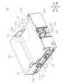
図1は、実施形態1に係る電気ユニット1の斜視図である。本実施形態では、便宜上、図に示す前後、左右、上下の各方向により、電気ユニット1の「前」、「後」、「左」、「右」、「上」、「下」を定義する。以下では、このように定義される前後、左右、上下の各方向を用いて説明する。(Embodiment 1)
FIG. 1 is a perspective view of the
電気ユニット1は、ジャンクションボックス2(第1電気装置)と、ジャンクションボックス2に装着されるECU(Engine Control Unit)3(第2電気装置)とを含む。ジャンクションボックス2及びECU3は着脱自在に結合されている。 The
図2は、電気ユニット1のジャンクションボックス2を示す斜視図であり、図3は、電気ユニット1のジャンクションボックス2を示す平面図である。 FIG. 2 is a perspective view showing the
ジャンクションボックス2は、絶縁性の樹脂製のケース部材20を有しており、ケース部材20には基板(図示せず)が収容されている。ケース部材20は、扁平な直方体形状をなしており、上部に、ECU3が装着される矩形の装着凹部21が形成されている。装着凹部21は、ケース部材20の後側半分程度の範囲に形成されている。ケース部材20の前側には、左右方向に長い長方形である上面201が設けられている。上面201の後側の辺縁には装着凹部21の底211まで垂直に延びる垂直面213が連設されている。上面201及び垂直面213が交差するエッジ部は面取りされている。 The
ケース部材20は、左側面204及び右側面202に、夫々コネクタ23を夫々備えている。詳しくは、左側面204及び右側面202には、前後方向に延びる長方形の貫通孔が夫々形成されており、各コネクタ23は、左側面204の貫通孔及び右側面202の貫通孔を介して、ケース部材20の外側に突出されている。 The
また、左側面204の上部には、後述するECU3のコネクタ31と係合する、長方形の切り欠き214が形成されており、右側面202の上部にも、ECU3のコネクタ31と係合する、長方形の切り欠き212が形成されている。切り欠き212、214は、右側面202及び左側面204を、装着凹部21の底211まで切り欠いて形成されている。 Further, a
更に、ケース部材20は、後側面203に、ECU3が装着凹部21に装着された場合における抜け防止のためのロック部24を備えている。ロック部24は、後側面203の略中央部に設けられており、後述するECU3の被ロック部33を係止する係止フック242と、係止フック242の左右両側に突設されて、平面視L字形状をなす一対のガイド241を有する。 Further, the
装着凹部21の底211には、後側端部に、後述するECU3の雌コネクタ34と接続する雄コネクタ25が突設されている(図3参照)。雄コネクタ25は、ケース部材20に収容された前記基板をECU3と電気的に接続させる。雄コネクタ25は、左右方向に長い長方形の筒の内側に立設された複数のピン251を有する。 A
また、ケース部材20の上面201には、装着凹部21の前側の両隅に軸受凹部22(係合凹部)が形成されている。軸受凹部22は、後述するECU3の係合軸部32と係合する。左側の軸受凹部22及び右側の軸受凹部22は同じ形状であり、以下では、左側の軸受凹部22についてのみ説明する。 Further, on the
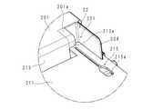
図4は、図2において円で囲まれた部分を拡大して示す拡大図である。即ち、図4は、左側の軸受凹部22を示している。軸受凹部22は凹部221を有しており、凹部221では、上面201の後側の隅が平面視矩形に切り欠かれ、切り欠かれた辺縁には、下方へ垂直に延びる内側壁が連設されている(図4の点線参照)。凹部221は、斯かる内側壁及び左側面204によって構成されている。 FIG. 4 is an enlarged view showing an enlarged portion surrounded by a circle in FIG. 2. That is, FIG. 4 shows the bearing
そして、上面201においては、軸受凹部22に係る辺縁のうち、左側面204と対向する辺縁には、上面201の面に沿う方向に、左側面204に向けて張り出している張出片201aが延設されている。
また、垂直面213においては、軸受凹部22に係る辺縁のうち、左側面204と対向する辺縁には、垂直面213の面に沿う方向に、左側面204に向けて張り出している張出片213aが延設されている。張出片213aは、前記辺縁において張出片201a寄りの上部にのみ設けられている。張出片201a及び張出片213aは一体形成されている。Then, on the
Further, in the
上述の如く、張出片201aは、軸受凹部22と係合軸部32との係合後、係合軸部32が上下方向に移動することを制限する。張出片213aは、軸受凹部22と係合軸部32との係合後、係合軸部32が前後方向に移動することを制限する。 As described above, the overhanging
装着凹部21の底211には、後述の如く、装着凹部21まで係合軸部32の摺動を案内する、スリット215が形成されている。スリット215は、装着凹部21の底211を内外に貫通しており、底211の左右方向の両端部であって、各軸受凹部22寄りの位置に夫々形成されている。左側のスリット215及び右側のスリット215は同じ形状であり、以下では、左側のスリット215についてのみ説明する。 As will be described later, the
左側のスリット215は略直線形状であり、対応する軸受凹部22の内側まで、前後方向に延びている。スリット215は、軸受凹部22から遠方の一端部に拡幅部215aを有している。即ち、スリット215は、軸受凹部22から遠方の拡幅部215aにて、左右方向の幅(寸法)が広くなっている。 The
図5は、電気ユニット1のECU3を上方から見た斜視図であり、図6は、電気ユニット1のECU3を下方からみた斜視図である。
ECU3は、車種や車のグレードに応じた制御機能を実現するためのプログラムが記憶されたマイクロコンピュータなどの電子素子が実装されている。FIG. 5 is a perspective view of the
The
図5-6に示すように、ECU3は、扁平な直方体形状のケース部材30を備えている。ケース部材30は、矩形の上面305を有しており、上面305に隣り合う、左側面301、右側面303、前側面302及び後側面304を有している。 As shown in FIG. 5-6, the
左側面301及び右側面303に、夫々コネクタ31を夫々備えている。詳しくは、左側面301及び右側面303には、前後方向に延びる長方形の貫通孔が夫々形成されており、各コネクタ31は、左側面301の貫通孔及び右側面303の貫通孔を介して、ケース部材30の外側に突出されている。
上述の如く、ジャンクションボックス2にECU3が装着された場合、ECU3の左側のコネクタ31及び右側のコネクタ31は、ジャンクションボックス2の左側面の204の切り欠き214及び右側面202の切り欠き212と係合する。A
As described above, when the
更に、ケース部材30は、後側面304に、ECU3がジャンクションボックス2の装着凹部21に装着された場合における抜け防止のための被ロック部33を備えている。被ロック部33は、後側面304の略中央部に設けられており、後側面304よりも下方に延びる中空矩形である。
ジャンクションボックス2にECU3が装着された場合、ジャンクションボックス2のロック部24の一対のガイド241に挟持されつつ、被ロック部33が下方へ挿入され、所定の位置で、ロック部24の係止フック242が被ロック部33の内側を通して被ロック部33と係合する。Further, the
When the
そして、ケース部材30は、上面305と対向する下面306(接触面)に、ジャンクションボックス2の雄コネクタ25に対応する雌コネクタ34を有している(図6参照)。ジャンクションボックス2にECU3が装着された場合、下面306は、ジャンクションボックス2の装着凹部21の底211と接する。 The
雌コネクタ34は、下面306の後側端部に設けられている。雌コネクタ34は、左右方向に長い長方形の凹部の内側に立設された複数のピン341を有する。ジャンクションボックス2にECU3が装着された場合、ECU3の雌コネクタ34にジャンクションボックス2の雄コネクタ25が嵌め込まれ、ジャンクションボックス2及びECU3が電気的に接続される。 The
ケース部材30の前側面302には、ジャンクションボックス2の軸受凹部22と係合する、係合軸部32(係合部)が設けられている。係合軸部32は、前側面302の左右方向の両端部に、前側面302の下側縁よりも少し上側に突設されている。左側の係合軸部32及び右側の係合軸部32は同じ形状であり、以下では、右側の係合軸部32についてのみ説明する。 The
図7は、図6において円で囲まれた部分を拡大して示す拡大図である。即ち、図7は、右側の係合軸部32を示している。 FIG. 7 is an enlarged view showing an enlarged portion surrounded by a circle in FIG. That is, FIG. 7 shows the
右側の係合軸部32は、前側面302の右端から前側面302に対して垂直に立ち上がる軸保持部321を有している。軸保持部321は突出先に向かって幅狭となっている。即ち、軸保持部321は先端部が基部よりも上下方向の寸法が小さい。また、軸保持部321の上面には、略三角形の補強リブ322が設けられている。 The right engaging
軸保持部321の先端から、左側の係合軸部32に向かって、係合軸323が延設されている。係合軸323は、柱形状の部分と、斯かる柱形状部分と前側面302との間に介在する基部とを含む。 The
係合軸部32は、後述の如く、係合軸部32がジャンクションボックス2の装着凹部21の底211上を摺動する際、スリット215に挟まれて移動するリブ324を有している。リブ324は、例えば、フィン形状である。 As will be described later, the engaging
また、係合軸部32は、外側面に、下面306と平行な第1面32a及び前側面302と平行な第2面32bを有しており、第1面32a及び第2面32bを繋ぐ湾曲面32cを更に有する。リブ324は、第2面32bより前方に出ないように、第1面32aから湾曲面32cに亘って突設されている。リブ324は先端の縁が湾曲している。 Further, the engaging
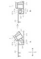
以下、ジャンクションボックス2へのECU3の装着方法について説明する。図8は、ジャンクションボックス2へのECU3の装着における所定の過程を説明する説明図であり、図9は、図8で示す過程を説明する断面図である。便宜上、図9は、ジャンクションボックス2及びECU3の右側を示している。 Hereinafter, a method of mounting the
先ず、作業者はジャンクションボックス2の装着凹部21の底211に形成されているスリット215に、ECU3の係合軸部32のリブ324を挟む。上述の如く、係合軸部32が前側面302の下側縁よりも少し上側に突設されているので、作業者は、図8Aに示すように、ECU3を斜めに立てて、係合軸部32のリブ324のうち、主に湾曲面32cに突設された部分を、スリット215の拡幅部215aに挟む。図9Aは、図8Aに対応する部分的縦断面図である。 First, the operator sandwiches the
上述の如く、係合軸部32の湾曲面32cまでリブ324が設けられているので、ECU3を斜めに立てた状態でスリット215内にリブ324を配置させることができ、また、図9Aに示すように、拡幅部215aではスリット215の幅が広いので、容易にリブ324をスリット215内に挟めることができる。 As described above, since the
このように、拡幅部215a内にリブ324を挟んだ状態のまま、作業者は、係合軸部32(ECU3)を、装着凹部21の底211上に、軸受凹部22まで摺動させる。図8Bは、係合軸部32がスリット215に沿って摺動する状態を示しており、図9Bは、図8Bに対応する部分的縦断面図である。この際、リブ324がスリット215に挟まれて挟持されているので、係合軸部32の摺動はスリット215に案内され、係合軸部32はスリット215に沿って軸受凹部22まで摺動する。 In this way, with the
以降、係合軸部32は、装着凹部21の底211と張出片213aとの間を通して凹部221内に差し込まれ、スリット215の他端で係合軸部32の摺動は止められる。 After that, the engaging
図10は、ジャンクションボックス2へのECU3の装着の際、係合軸部32が凹部221内に差し込まれた状態を示す部分的縦断面図である。
係合軸部32が凹部221内に差し込まれ、係合軸部32の摺動は止められた場合(図10A参照)、作業者は、係合軸323を軸として、係合軸323回りに、下方へECU3を回動させる(図8Bの白抜き矢印参照)。FIG. 10 is a partial vertical sectional view showing a state in which the engaging
When the engaging
これによって、ECU3の下面306が装着凹部21の底211と当接し、係合軸323は、装着凹部21の底211から離れ、上側に移動して張出片201aの内側に当たり、係合軸部32と軸受凹部22との係合が完了する(図10B参照)。また、ジャンクションボックス2のロック部24に、ECU3の被ロック部33が嵌め込まれ、上述の如く、ロック部24と被ロック部33とが係合する。 As a result, the
係合軸部32と軸受凹部22との係合が完了した場合、係合軸部32の上下方向への移動が張出片201aによって制限され、係合軸部32の前後方向への移動が張出片213aによって制限される。更に、ロック部24と被ロック部33とが係合しているので、ECU3がジャンクションボックス2から外れることを確実に防止できる。 When the engagement between the engaging
そして、この際、ECU3の雌コネクタ34にジャンクションボックス2の雄コネクタ25が嵌め込まれ、雄コネクタ25のピン251と雌コネクタ34のピン341とが接触し、ECU3及びジャンクションボックス2が電気的に接触される。
以上により、ECU3のジャンクションボックス2への装着が完了される。At this time, the
This completes the mounting of the
上述の如く、ジャンクションボックス2へのECU3の装着には、係合軸部32を軸受凹部22に係合させるためには、係合軸部32を装着凹部21の底211上で摺動させて、装着凹部21の底211と張出片213aとの間を通して凹部221内に差し込む作業が必要である。斯かる作業は、係合軸部32の摺動を軸受凹部22まで案内する案内部材を用いることにより、作業性を高めることができる。 As described above, in order to mount the
一般には、係合軸部32を摺動させる際、ジャンクションボックス2の装着凹部21に係る左側面204及び右側面202を案内部材として用いることができる。しかし、本実施形態の電気ユニット1においては、ECU3に設けられたコネクタ31に対応すべく、左側面204及び右側面202が切り欠かれており、案内部材として用いることができない。 Generally, when sliding the engaging
これに対して、本実施形態の電気ユニット1では、上述したように、ジャンクションボックス2が装着凹部21の底211にスリット215を備え、ECU3が係合軸部32にリブ324を備えており、係合軸部32の摺動が軸受凹部22まで案内される。従って、係合軸部32を軸受凹部22に係合させる作業の作業性を高めることができる。 On the other hand, in the
また、上述したように、係合軸部32の摺動において左側面204及び右側面202が案内部材としての役割を行わないので、左側面204に切り欠き214が形成し、右側面202に切り欠き212を形成しても、係合軸部32を摺動させて係合軸部32と軸受凹部22とを係合させるには何ら問題が生じない。よって、ジャンクションボックス2の設計変更における自由度が高まる。 Further, as described above, since the
以上においては、リブ324の厚みが均一である場合を例に挙げて説明したが、これに限定されるものではない。係合軸部32の第1面32aから湾曲面32cに亘って突設されているリブ324が、突出先の先端部にて厚みが減少するように構成しても良い。この場合、リブ324がスリット215内に挟みやすくなるという効果を奏する。 In the above, the case where the thickness of the
(実施形態2)
実施形態2に係る電気ユニット1は、実施形態1と同様の構成であるが、ジャンクションボックス2における軸受凹部22及びスリット215の構成、並びに、ECU3における係合軸部32の構成において相違する。(Embodiment 2)
The
図11は、実施形態2に係る電気ユニット1における左側の軸受凹部22の近傍を示す図である。実施形態2の電気ユニット1において、左側の軸受凹部22及び右側の軸受凹部22は同じ形状であり、左側のスリット215及び右側のスリット215も同じ形状であるので、以下では、左側の軸受凹部22及び左側のスリット215についてのみ説明する。 FIG. 11 is a diagram showing the vicinity of the bearing
軸受凹部22は、実施形態1と同様に、凹部221を有している。凹部221では、上面201の後側の両隅が平面視矩形に切り欠かれており、切り欠かれた辺縁には、下方へ垂直に延びる内側壁が連設されている。前記内側壁のうち、上面201及び左側面204と隣り合う阻止壁222は、後述の如く、係合軸部32の摺動を止める。 The bearing
実施形態2の電気ユニット1においても、実施形態1と同様、上面201に、左側面204に向けて張り出している張出片201aが延設されており、また、垂直面213の上部に、左側面204に向けて張り出している張出片213aが延設されている。 In the
装着凹部21の底211には、装着凹部21まで係合軸部32の摺動を案内する、スリット215が形成されている。スリット215は、底211の左右方向の両端部であって、各軸受凹部22寄りの位置に夫々形成されている。 A
スリット215は略直線形状であり、対応する軸受凹部22の内側まで、前後方向に延びている。スリット215は、軸受凹部22から遠方の一端部に拡幅部215aを有している。スリット215は、軸受凹部22の底を含み、軸受凹部22の底に連設された阻止壁222にまで形成されている。即ち、阻止壁222には、上部から下端まで延びるスリット215が形成されており、軸受凹部22の底に形成されたスリット215に繋がっている。換言すれば、スリット215は、装着凹部21の底211から、軸受凹部22の底を亘って阻止壁222まで連続的に形成されている。 The
図12は、実施形態2に係る電気ユニット1における右側の係合軸部32の近傍を示す図である。実施形態2の電気ユニット1において、左側の係合軸部32及び右側の係合軸部32は同じ形状であり、以下では、右側の係合軸部32についてのみ説明する。 FIG. 12 is a diagram showing the vicinity of the
右側の係合軸部32は、実施形態1と同様に、前側面302の右端から前側面302に対して垂直に立ち上がる軸保持部321を有しており、軸保持部321の上面には補強リブ322が設けられている。また、軸保持部321の先端から、左側の係合軸部32に向かって、係合軸323が延設されている。 Similar to the first embodiment, the right engaging
また、係合軸部32は、係合軸部32がジャンクションボックス2の装着凹部21の底211上を摺動する際、スリット215に挟まれて移動するリブ324Aを有している。リブ324Aは、例えば、フィン形状である。 Further, the engaging
係合軸部32は、下面306と平行な第1面32aと、前側面302と平行な第2面32bと、第1面32a及び第2面32bを繋ぐ湾曲面32cとを有する。リブ324Aは、第1面32aから湾曲面32cを亘って第2面32bまで突設されている。リブ324Aは先端の縁が湾曲している。 The engaging
以上、実施形態2に係る電気ユニット1における、ジャンクションボックス2へのECU3の装着方法について説明する。
先ず、作業者はジャンクションボックス2の装着凹部21の底211に形成されているスリット215に、ECU3の係合軸部32のリブ324Aを挟む。詳しくは、作業者は、図8Aに示すように、ECU3を斜めに立てて、係合軸部32のリブ324Aのうち、主に湾曲面32cに突設された部分を、スリット215の拡幅部215aに挟む(図9A参照)。The method of mounting the
First, the operator sandwiches the
このように、拡幅部215a内にリブ324Aを挟んだ状態のまま、作業者は、係合軸部32(ECU3)を、軸受凹部22まで摺動させる。この際、リブ324Aがスリット215に挟まれて挟持されているので、係合軸部32の摺動はスリット215に案内され、係合軸部32はスリット215に沿って軸受凹部22まで摺動する(図8B及び図9B参照)。 In this way, with the
係合軸部32は、装着凹部21の底211と張出片213aとの間を通して凹部221内に差し込まれ、凹部221の阻止壁222と当たることによって係合軸部32の摺動が止められる。 The engaging
上述の如く、実施形態2に係る電気ユニット1においては、リブ324Aが、係合軸部32の第1面32aから湾曲面32cを亘って第2面32bまで突設されており、スリット215が装着凹部21の底211から、軸受凹部22の底を亘って阻止壁222まで連続的に形成されている。 As described above, in the
従って、係合軸部32が阻止壁222に当たり、係合軸部32の摺動が止められた場合でも、リブ324Aにおいて、第2面32bに突設された部分は阻止壁222のスリット215に挟まれたままであり、第1面32aに突設された部分は軸受凹部22の底のスリット215に挟まれたままである。即ち、係合軸部32が装着凹部21の底211上を摺動して凹部221内に差し込まれ、凹部221の阻止壁222と当たって摺動が止められるまで、係合軸部32の摺動が案内される。よって、実施形態2に係る電気ユニット1では、より的確に係合軸部32の摺動が案内される。 Therefore, even when the engaging
以降、作業者は、係合軸323を軸として、係合軸323回りに、下方へECU3を回動させる(図8Bの白抜き矢印参照)。これによって、ECU3の下面306が装着凹部21の底211と当接し、係合軸323は上側に移動して張出片201aの内側に当たり、係合軸部32と軸受凹部22との係合が完了する(図10B参照)。また、作業者は、ジャンクションボックス2のロック部24と、ECU3の被ロック部33とを係合させる。そして、この際、ECU3の雌コネクタ34にジャンクションボックス2の雄コネクタ25が嵌め込まれ、ECU3及びジャンクションボックス2が電気的に接触される。
以上により、ECU3がジャンクションボックス2の装着凹部21内への装着が完了される。Hereinafter, the operator rotates the
As described above, the
上述の如く、本実施形態の電気ユニット1では、係合軸部32が軸受凹部22内に差し込まれるまで、係合軸部32の摺動が案内される。従って、係合軸部32を軸受凹部22に係合させる作業の作業性に加え、作業の正確性も高めることができる。 As described above, in the
実施形態1と同様の部分については、同一の符号を付して詳細な説明を省略する。 The same parts as those in the first embodiment are designated by the same reference numerals, and detailed description thereof will be omitted.
今回開示された実施形態はすべての点で例示であって、制限的なものではないと考えられるべきである。本発明の範囲は、上記した意味ではなく、特許請求の範囲によって示され、特許請求の範囲と均等の意味及び範囲内でのすべての変更が含まれることが意図される。 The embodiments disclosed this time should be considered to be exemplary in all respects and not restrictive. The scope of the present invention is indicated by the scope of claims, not the above-mentioned meaning, and is intended to include all modifications within the meaning and scope equivalent to the scope of claims.
1 電気ユニット
2 ジャンクションボックス
3 ECU
20 ケース部材
21 装着凹部
22 軸受凹部
23 コネクタ
24 ロック部
25 雄コネクタ
30 ケース部材
31 コネクタ
32 係合軸部
32a 第1面
32b 第2面
32c 湾曲面
33 被ロック部
34 雌コネクタ
201 上面
201a 張出片
202 右側面
203 後側面
204 左側面
211 底
212 切り欠き
213 垂直面
213a 張出片
214 切り欠き
215 スリット
215a 拡幅部
221 凹部
222 阻止壁
241 ガイド
242 係止フック
251 ピン
301 左側面
302 前側面
303 右側面
304 後側面
305 上面
306 下面
321 軸保持部
322 補強リブ
323 係合軸
324,324A リブ
341 ピン1
20
202
Claims (5)
Translated fromJapanese前記一面に形成され、前記係合凹部まで前記係合部の摺動を案内するスリットと、
前記係合部に設けられ、前記係合部の摺動の際、前記スリットに挟まれて移動するリブとを備え、
前記第2電気装置は前記一面と接する接触面を有する筐体形状であり、
前記係合部は、
前記接触面と隣り合う側面に突設されており、
前記接触面及び前記側面に平行な第1面及び第2面と、前記第1面及び前記第2面を繋ぐ湾曲面とを有し、
前記リブは前記第1面及び前記湾曲面に突設されている電気ユニット。A second electric device having a housing shape having an engaging recess provided on one surface and an engaging portion that slides on the one surface and engages with the engaging recess, and is mounted on the one surface. An electrical unit that includes an electrical device
A slit formed on the one surface and guiding the sliding of the engaging portion to the engaging recess,
It is provided with a rib provided in the engaging portion and moves while being sandwiched between the slits when the engaging portion slides.
The second electric device has a housing shape having a contact surface in contact with the one surface.
The engaging portion is
It is projected on the side surface adjacent to the contact surface and
It has a first surface and a second surface parallel to the contact surface and the side surface, and a curved surface connecting the first surface and the second surface.
The rib is an electric unit projecting from the first surface and the curved surface .
請求項1に記載の電気ユニット。The electric unit according to claim 1, wherein the slit has a widening portion at an end far from the engaging recess.
請求項1又は2に記載の電気ユニット。The electric unit according to claim 1or 2 , wherein the rib has a narrow width toward the protruding end.
前記スリットは前記一面から前記阻止壁に亘って形成されており、
前記リブは前記第1面から前記第2面に亘って突設されている
請求項1から3のいずれか一項に記載の電気ユニット。It is connected to the one surface and has a blocking wall for stopping the sliding of the engaging portion in the engaging recess.
The slit is formed from one surface of the slit to the blocking wall.
The electric unit according toany one of claims 1 to 3, wherein the rib projects from the first surface to the second surface.
前記係合部は、前記接触面と隣り合う側面に突設されており、前記接触面及び前記側面に平行な第1面及び第2面と、前記第1面及び前記第2面を繋ぐ湾曲面とを有し、リブが前記第1面及び前記湾曲面に突設されており、
前記一面に設けられて前記係合凹部まで延びるスリットの両端部のうち、前記係合凹部から遠方の一端部に、前記係合部に設けられた前記リブを挟み、
前記スリットに沿って、前記係合部を前記一面上に摺動させ、
前記スリットの他端部で、前記係合部と前記係合凹部とを係合させる
装着方法。A housing-shaped second electric device having an engaging portion engaged with the engaging recess andhaving a contact surface in contact with the one surface in a housing-shaped first electric device provided with an engaging recess on one surface. It is a mounting method to mount
The engaging portion is projected on a side surface adjacent to the contact surface, and is curved to connect the contact surface and the first surface and the second surface parallel to the side surface, and the first surface and the second surface. It has a surface, and ribs are projected onto the first surface and the curved surface.
Of both ends of the slit provided on one surface and extending to the engaging recess,the rib provided in the engaging portion is sandwiched at one end far from the engaging recess.
The engaging portion is slid onto the one surface along the slit.
A mounting method in which the engaging portion and the engaging recess are engaged with each other at the other end of the slit.
Priority Applications (5)
| Application Number | Priority Date | Filing Date | Title |
|---|---|---|---|
| JP2021073412AJP7031777B1 (en) | 2021-04-23 | 2021-04-23 | Electric unit and mounting method |
| JP2022025921AJP7264292B2 (en) | 2021-04-23 | 2022-02-22 | Electric unit and mounting method |
| US18/555,816US20240213717A1 (en) | 2021-04-23 | 2022-03-22 | Electrical unit and attachment method |
| CN202280027784.XACN117121316A (en) | 2021-04-23 | 2022-03-22 | Electrical unit and method of assembly |
| PCT/JP2022/012984WO2022224665A1 (en) | 2021-04-23 | 2022-03-22 | Electric unit and installation method |
Applications Claiming Priority (1)
| Application Number | Priority Date | Filing Date | Title |
|---|---|---|---|
| JP2021073412AJP7031777B1 (en) | 2021-04-23 | 2021-04-23 | Electric unit and mounting method |
Related Child Applications (1)
| Application Number | Title | Priority Date | Filing Date |
|---|---|---|---|
| JP2022025921ADivisionJP7264292B2 (en) | 2021-04-23 | 2022-02-22 | Electric unit and mounting method |
Publications (2)
| Publication Number | Publication Date |
|---|---|
| JP7031777B1true JP7031777B1 (en) | 2022-03-08 |
| JP2022167549A JP2022167549A (en) | 2022-11-04 |
Family
ID=81212872
Family Applications (1)
| Application Number | Title | Priority Date | Filing Date |
|---|---|---|---|
| JP2021073412AActiveJP7031777B1 (en) | 2021-04-23 | 2021-04-23 | Electric unit and mounting method |
Country Status (4)
| Country | Link |
|---|---|
| US (1) | US20240213717A1 (en) |
| JP (1) | JP7031777B1 (en) |
| CN (1) | CN117121316A (en) |
| WO (1) | WO2022224665A1 (en) |
Citations (2)
| Publication number | Priority date | Publication date | Assignee | Title |
|---|---|---|---|---|
| JP2017004523A (en) | 2015-06-12 | 2017-01-05 | 任天堂株式会社 | Information processing system, information processor, operation device, and accessory equipment |
| JP2017183567A (en) | 2016-03-31 | 2017-10-05 | 日本電気株式会社 | Apparatus assembly structure |
Family Cites Families (3)
| Publication number | Priority date | Publication date | Assignee | Title |
|---|---|---|---|---|
| JPS574283U (en)* | 1980-06-10 | 1982-01-09 | ||
| JP2007181050A (en)* | 2005-12-28 | 2007-07-12 | Matsushita Electric Ind Co Ltd | Mobile device |
| WO2016063842A1 (en)* | 2014-10-23 | 2016-04-28 | 住友電装株式会社 | Electrical connection box |
- 2021
- 2021-04-23JPJP2021073412Apatent/JP7031777B1/enactiveActive
- 2022
- 2022-03-22USUS18/555,816patent/US20240213717A1/enactivePending
- 2022-03-22WOPCT/JP2022/012984patent/WO2022224665A1/ennot_activeCeased
- 2022-03-22CNCN202280027784.XApatent/CN117121316A/enactivePending
Patent Citations (2)
| Publication number | Priority date | Publication date | Assignee | Title |
|---|---|---|---|---|
| JP2017004523A (en) | 2015-06-12 | 2017-01-05 | 任天堂株式会社 | Information processing system, information processor, operation device, and accessory equipment |
| JP2017183567A (en) | 2016-03-31 | 2017-10-05 | 日本電気株式会社 | Apparatus assembly structure |
Also Published As
| Publication number | Publication date |
|---|---|
| CN117121316A (en) | 2023-11-24 |
| US20240213717A1 (en) | 2024-06-27 |
| WO2022224665A1 (en) | 2022-10-27 |
| JP2022167549A (en) | 2022-11-04 |
Similar Documents
| Publication | Publication Date | Title |
|---|---|---|
| US9882310B2 (en) | Connection structure and apparatus unit | |
| JP6050196B2 (en) | Wire harness and connector | |
| JP6046571B2 (en) | Connector and wire harness | |
| JP6492029B2 (en) | connector | |
| JP5990140B2 (en) | connector | |
| WO2015020195A1 (en) | Wire harness and connector | |
| JP6050197B2 (en) | Wire harness and connector | |
| US9722353B2 (en) | Connector with alignment function | |
| JP2019129078A (en) | Lever type connector | |
| JP7031777B1 (en) | Electric unit and mounting method | |
| JP6447744B2 (en) | Connector device | |
| JP7264292B2 (en) | Electric unit and mounting method | |
| JP7068252B2 (en) | Electrical junction box unit | |
| JP3804830B2 (en) | connector | |
| JP2018147781A (en) | Connector and connector assembly | |
| JP2009027770A (en) | Protector | |
| JP2022083276A (en) | connector | |
| JP2020167084A (en) | Electrical connector and electrical connector with circuit board | |
| JP7098549B2 (en) | Fixing members and wire harness | |
| JP7684012B2 (en) | case | |
| US12410643B2 (en) | Door lock assembly | |
| JP6774283B2 (en) | Connector device | |
| KR20230159277A (en) | Connector | |
| JP2008226485A (en) | Valve socket | |
| JP2022114956A (en) | Holder with terminal |
Legal Events
| Date | Code | Title | Description |
|---|---|---|---|
| A621 | Written request for application examination | Free format text:JAPANESE INTERMEDIATE CODE: A621 Effective date:20210804 | |
| A871 | Explanation of circumstances concerning accelerated examination | Free format text:JAPANESE INTERMEDIATE CODE: A871 Effective date:20210804 | |
| A131 | Notification of reasons for refusal | Free format text:JAPANESE INTERMEDIATE CODE: A131 Effective date:20211005 | |
| A521 | Request for written amendment filed | Free format text:JAPANESE INTERMEDIATE CODE: A523 Effective date:20211129 | |
| TRDD | Decision of grant or rejection written | ||
| A01 | Written decision to grant a patent or to grant a registration (utility model) | Free format text:JAPANESE INTERMEDIATE CODE: A01 Effective date:20220125 | |
| A61 | First payment of annual fees (during grant procedure) | Free format text:JAPANESE INTERMEDIATE CODE: A61 Effective date:20220207 | |
| R150 | Certificate of patent or registration of utility model | Ref document number:7031777 Country of ref document:JP Free format text:JAPANESE INTERMEDIATE CODE: R150 | |
| R250 | Receipt of annual fees | Free format text:JAPANESE INTERMEDIATE CODE: R250 |